

Jacuzzi Comfort Plus Bath Series, AMIGA PLUS, CETRA 536 PLUS, SIGNA 5 PLUS, SIGNA 6 PLUS Installation And Operating Instructions Manual
...Page 1

COMFORT PLUS BATH SERIES
INST ALLA TION AND OPERA TING INSTRUCTIONS
Installer: Leave this manual for homeowner.
Homeowner: Read this manual and keep for future reference.
Jacuzzi Whirlpool Bath
©
BP43000 2/05
Page 2

IMPORT ANT SAFETY INSTRUCTIONS
READ AND FOLLOW ALL INSTRUCTIONS
SAVE THESE INSTRUCTIONS
ENGLISH
CAUTION: TEST THE GROUND FAULT CIRCUIT INTERRUPTER PROTECTING THIS APPLIANCE PERIODI-
CALLY IN ACCORDANCE WITH MANUFACTURER'S INSTRUCTIONS.
WARNING: RISK OF ACCIDENTAL INJURY OR DROWNING; CHILDREN SHOULD NOT USE HYDROMASSAGE
BATHTUB WITHOUT ADULT SUPERVISION.
WARNING: TO AVOID INJURY, EXERCISE CAUTION WHEN ENTERING OR EXITING THE HYDROMASSAGE
BATHTUB
WARNING: RISK OF ACCIDENTAL INJURY OR DROWNING; DO NOT USE HYDROMASSAGE BATHTUB
UNLESS ALL SUCTION GUARDS ARE INSTALLED TO PREVENT BODY AND HAIR ENTRAPMENT.
WARNING: KEEP BODY AND HAIR A MINIMUM OF 6" AWAY FROM SUCTION FITTING AT ALL TIMES WHEN
THE WHIRLPOOL SYSTEM IS OPERATING. HAIR LONGER THAN SHOULDER LENGTH SHOULD BE SECURED
CLOSE TO THE HEAD.
WARNING: NEVER DROP OR INSERT ANY OBJECT INTO ANY OPENING.
WARNING: RISK OF ELECTRICAL SHOCK; DO NOT PERMIT ELECTRICAL APPLIANCES (SUCH AS HAIR
DRYER, LAMP, TELEPHONE, RADIO OR TELEVISION) WITHIN 60" (1.5 M) OF THIS HYDROMASSAGE
BATHTUB.
WARNING: RISK OF ACCIDENTAL INJURY OR DROWNING; DO NOT USE DRUGS OR ALCOHOL BEFORE OR
DURING THE USE OF HYDROMASSAGE BATHTUB EQUIPPED WITH A HEATER TO AVOID UNCONSCIOUSNESS AND POSSIBLE DROWNING.
WARNING: RISK OF FETAL INJURY; PREGNANT OR POSSIBLY PREGNANT WOMEN SHOULD CONSULT A
PHYSICIAN BEFORE USING A HYDROMASSAGE BATHTUB EQUIPPED WITH A HEATER.
WARNING: RISK OF HYPERTHERMIA AND POSSIBLE DROWNING; DO NOT USE A HYDROMASSAGE
BATHTUB EQUIPPED WITH A HEATER IMMEDIATELY FOLLOWING STRENUOUS EXERCISE.
WARNING: RISK OF HYPERTHERMIA AND POSSIBLE DROWNING; WATER TEMPERATURE IN EXCESS OF
104° F (40° C) MAY BE INJURIOUS TO YOUR HEALTH. CHECK AND ADJUST WATER TEMPERATURE BEFORE
USE.
WARNING: RISK OF HYPERTHERMIA; PEOPLE USING MEDICATIONS AND/OR HAVING AN ADVERSE
MEDICAL HISTORY SHOULD CONSULT A PHYSICIAN BEFORE USING A HYDROMASSAGE BATHTUB
EQUIPPED WITH A HEATER.
AN EQUIPMENT GROUNDING TERMINAL IS PROVIDED IN THE FIELD WIRING COMPARTMENT. TO
REDUCE THE RISK OF ELECTRICAL SHOCK, THIS TERMINAL MUST BE CONNECTED T O THE GROUNDING
MEANS PROVIDED IN THE ELECTRICAL SUPPLY PANEL WITH A CONNECTOR EQUIVALENT IN SIZE TO
THE CIRCUIT CONNECTORS SUPPLYING THIS EQUIPMENT.
Page 3

PRECAUTIONS
• Do not operate the whirlpool system unless the bath is filled with water to at least 1" (25 mm) above the highest
jet.
• Never drop or insert any object into any opening.
• Do not use oil-based bath additives in your whirlpool bath.
• When cleaning your bath, do not use abrasive substances which will damage the bath's surface.
• To prevent discoloration of the acrylic finish, do not fill the bath with water in excess of 140° F (60° C)
• The whirlpool system should be purged at least twice a month. For your convenience, we have developed a
plumbing system cleaner (Systems Clean™) specifically for whirlpool baths. For availability call 1-800-288-4002.
• Use this unit only for its intended purpose as described in this manual. Do not use attachments not recommended by the manufacturer.
• This unit must be connected only to a supply circuit that is protected by a ground fault circuit interrupter (GFCI).
Such a GFCI should be provided by the installer and should be tested on a routine basis. To test the GFCI, push
the test button. The GFCI should interrupt power. Push the reset button. Power should be restored. If the GFCI
fails to operate in this manner, there is a ground current flowing, indicating a possibility of an electric shock. Do
not use this unit. Disconnect the unit and have the problem corrected by a qualified electrician before using.
• A pressure wire connector is provided on the exterior of the motor to permit connection of an No. 8 AWG (8.4
mm) solid copper bonding conductor between this unit and all other electric equipment and exposed metal in the
vicinity, as needed to comply with local requirements.
• This unit should be electrically grounded and installed by a licensed contractor, electrician, and plumber.
• For built-in and drop-in units, install to permit access for servicing.
Note: This is a professional grade product. A knowledge of construction techniques, plumbing and electrical installation according to codes are required for proper installation and user satisfaction. W e recommend
that a licensed contractor perform the installation of all Jacuzzi Whirlpool Bath© products. Our warranty
does not cover improper installation related problems.
ENGLISH
Page 4
ADDENDUM
r
Safety Instructions Change
IMPORTANT SAFETY INSTRUCTIONS
READ AND FOLLOW ALL INSTRUCTIONS
SAVE THESE INSTRUCTIONS
INSTRUCTIONS PERTAINING TO A RISK OF FIRE, ELECTRIC
SHOCK, OR INJURY TO PERSONS
WARNING — WHEN USING THIS UNIT, BASIC PRECAUTIONS SHOULD ALWAYS BE FOLLOWED,
INCLUDING THE FOLLOWING:
DANGER: TO REDUCE THE RISK OF INJURY, DO NOT PERMIT CHILDREN TO USE THIS UNIT
UNLESS THEY ARE CLOSELY SUPERVISED A T ALL TIMES.
WARNING — USE THIS UNIT ONL Y FOR ITS INTENDED USE AS DESCRIBED IN THIS MANUAL. DO
NOT USE ATTACHMENTS NOT RECOMMENDED BY THE MANUFACTURER.
WARNING — NEVER DROP OR INSERT ANY OBJECT INT O ANY OPENING.
WARNING — DO NOT OPERATE THIS UNIT WITHOUT THE GUARD OVER THE SUCTION FITTING.
WARNING — THIS UNIT MUST BE CONNECTED ONLY TO A SUPPLY CIRCUIT THAT IS PROTECTED
BY A GROUND FAULT CIRCUIT INTERRUPTER (GFCI). SUCH A GFCI SHOULD BE PROVIDED BY
THE INSTALLER AND SHOULD BE TESTED ON A ROUTINE BASIS. TO TEST THE GFCI, PUSH THE
TEST BUTTON. THE GFCI SHOULD INTERRUPT POWER. PUSH THE RESET BUTTON. POWER
SHOULD BE RESTORED. IF THE GFCI FAILS TO OPERATE IN THIS MANNER, THE GFCI IS
DEFECTIVE. IF THE GFCI INTERRUPTS POWER TO THE BATHTUB WITHOUT THE TEST BUTTON
BEING PUSHED, A GROUND CURRENT FLOWING, INDICATING A POSSIBILITY OF AN ELECTRIC
SHOCK. DO NOT USE THIS HYDROMASSAGE BATHTUB. DISCONNECT THE HYDROMASSAGE
BATHTUB AND HAVE THE PROBLEM CORRECTED BY A QUALIFIED SERVICE REPRESENTATIVE
BEFORE USING.
WARNING: (FOR PERMANENTLY CONNECTED UNITS) A GREEN COLORED TERMINAL (OR A WIRE
CONNECTOR MARKED “G”, “GR”, “GROUND”, OR “GROUNDING”) IS PROVIDED WITHIN THE TERMINAL
COMPARTMENT. TO REDUCE THE RISK OF ELECTRIC SHOCK, CONNECT THE TERMINAL OR
CONNECTOR TO THE GROUNDING TERMINAL OF YOUR ELECTRIC SERVICE OR SUPPLY PANEL WITH
A CONDUCTOR EQUIVALENT IN SIZE TO THE CIRCUIT CONDUCTORS SUPPLYING THIS EQUIPMENT.
OPERA TING INSTRUCTIONS
WARNING — PROLONGED IMMERSION IN HOT WATER MAY INDUCE HYPERTHERMIA. HYPER-
THERMIA OCCURS WHEN THE INTERNAL TEMPERA TURE OF THE BODY REACHES A LEVEL SEV ERAL DEGREES ABOVE THE NORMAL BODY TEMPERATURE OF 98.6°F. THE SYMPTOMS OF
HYPERTHERMIA INCLUDE AN INCREASE IN THE INTERNAL TEMPERATURE OF THE BODY , DIZZINESS, LETHARGY, DROWSINESS AND FAINTING. THE EFFECTS OF HYPERTHERMIA INCLUDE:
A) FAILURE TO PERCEIVE HEAT
B) FAILURE TO RECOGNIZE THE NEED TO EXIT THE SPA OR HOT TUB,
C) UNAWARENESS OF IMPENDING HAZARD,
D) FETAL DAMAGE IN PREGNANT WOMEN,
E) PHYSICAL INABILITY TO EXIT THE SPA OR HOT TUB, AND
F) UNCONSCIOUSNESS RESULTING IN DANGER OF DROWNING.
WARNING — THE USE OF ALCOHOL, DRUGS OR MEDICATION CAN GREATLY INCREASE THE
RISK OF FATAL HYPERTHERMIA.
WARNING — DO NOT TAMPER WITH USER-OPERATED CONTROLS OR SUCH DEVICES.
©
Printed on Recycled Pape
2005 Jacuzzi Whirlpool Bath DA38000A 06/05
Printed in the U.S.A.
Page 5

INST ALLATION INSTRUCTIONS
r
WARNING — WHEN USING THIS UNIT, BASIC PRECAUTIONS SHOULD ALWAYS BE FOLLOWED,
INCLUDING THE FOLLOWING:
DANGER — RISK OF ELECTRIC SHOCK. CONNECT ONLY TO A CIRCUIT PROTECTED BY A GROUND
FAULT CIRCUIT INTERRUPTER (GFCI).
CAUTION
PERIODICALLY IN ACCORDANCE WITH MANUFACTURER’S INSTRUCTIONS.
WARNING
USE ATTACHMENTS NOT RECOMMENDED BY THE MANUFACTURERS.
WARNING
WARNING
WHEN THE HYDROMASSAGE SYSTEM IS OPERATING. HAIR LONGER THAN SHOULDER LENGTH
SHOULD BE SECURED CLOSE TO THE HEAD.
WARNING
DRYER, LAMP, TELEPHONE, RADIO OR TELEVISION) WITHIN 60" (1.5 M) OF THIS HYDROMASSAGE BATHTUB.
WARNING
BEFORE OR DURING THE USE OF HYDROMASSAGE BATHTUB EQUIPPED WITH A HEATER TO AVOID
UNCONSCIOUSNESS AND POSSIBLE DROWNING.
WARNING
CONSULT A PHYSICIAN BEFORE USING A HYDROMASSAGE BATHTUB EQUIPPED WITH A HEATER.
WARNING
BATHTUB EQUIPPED WITH A HEATER IMMEDIATELY FOLLOWING STRENUOUS EXERCISE.
WARNING
EXCESS OF 104°F (40°C) MAY BE INJURIOUS TO YOUR HEALTH. CHECK AND ADJUST WATER
TEMPERATURE BEFORE USE.
WARNING
MEDICAL HISTORY SHOULD CONSULT A PHYSICIAN BEFORE USING A HYDROMASSAGE BATHTUB
EQUIPPED WITH A HEATER.
— TEST THE GROUND FAULT CIRCUIT INTERRUPTER PROTECTING THIS APPLIANCE
— USE THIS UNIT ONLY FOR ITS INTENDED USE AS DESCRIBED IN THIS MANUAL. DO NOT
— TO AVOID INJURY, EXERCISE CAUTION WHEN ENTERING OR EXITING THE HYDROMASSAGE BATHTUB.
— KEEP BODY AND HAIR A MINIMUM OF 6" AWAY FROM SUCTION FITTING AT ALL TIMES
— RISK OF ELECTRICAL SHOCK; DO NOT PERMIT ELECTRICAL APPLIANCES (SUCH AS HAIR
— RISK OF ACCIDENTAL INJURY OR DROWNING; DO NOT USE DRUGS OR ALCOHOL
— RISK OF FETAL INJURY; PREGNANT OR POSSIBLY PREGNANT WOMEN SHOULD
— RISK OF HYPERTHERMIA AND POSSIBLE DROWNING; DO NOT USE A HYDROMASSAGE
— RISK OF HYPERTHERMIA AND POSSIBLE DROWNING; WATER TEMPERATURE IN
— RISK OF HYPERTHERMIA; PEOPLE USING MEDICATIONS AND/OR HAVING AN ADVERSE
FOR BUILT-IN AND DROP-IN UNITS, INSTALL TO PERMIT ACCESS FOR SERVICING.
THIS UNIT SHOULD BE ELECTRICALLY GROUNDED AND INSTALLED BY A LICENSED CONTRACTOR,
ELECTRICIAN, AND PLUMBER.
BUILDING MATERIALS AND WIRING SHOULD BE ROUTED AWAY FROM THE MOTOR/PUMP OR
BLOWER OR OTHER HEAT PRODUCING COMPONENTS OF THIS UNIT.
A PRESSURE WIRE CONNECTOR IS PROVIDED ON THE EXTERIOR OF THE MOTOR/PUMP AND
HEATER TO PERMIT CONNECTION OF AN NO. 8 AWG (8.4 MM) SOLID COPPER BONDING CONDUCTOR
BETWEEN THIS UNIT AND ALL OTHER ELECTRIC EQUIPMENT AND EXPOSED METAL IN THE VICINITY,
AS NEEDED TO COMPLY WITH LOCAL REQUIREMENTS.
PRECAUTIONS
••
• Do not operate the hydromassage system unless the bath is filled with water to at least 1" above the highest jet.
••
••
• Do not immerse the control panel by overfilling the bath.
••
••
• Do not use oil-based bath additives in your hydromassage bath.
••
••
• When cleaning your bath, do not use abrasive substances which will damage the bath's surface.
••
••
• To prevent discoloration of the acrylic finish, do not fill the bath with water in excess of 140°F (60°C).
••
NOTE: This is a professional grade product. A knowledge of construction techniques, plumbing and electrical installation according to codes are required for proper installation and user satisfaction. W e recommend
that a licensed contractor perform the installation of all Jacuzzi Whirlpool Bath© products. Our warranty
does not cover improper installation related problems.
PRODUCT SPECIFICATIONS ARE SUBJECT TO CHANGE WITHOUT NOTICE.
USE INSTALLATION INSTRUCTIONS SUPPLIED WITH PRODUCT.
The Company has obtained applicable code (standards) listings generally available on a national basis for products of this type.
It is the responsibility of the installer/owner to determine specific local code compliance prior to installation of the product. The
Company makes no representation or warranty regarding, and will not be responsible for any code compliance.
©
Printed on Recycled Pape
2005 Jacuzzi Whirlpool Bath DA38000A 06/05
Printed in the U.S.A.
Page 6

CONTENTS
Specifications _________________________________________________________________________ 1-2
Roughing-in Reference _________________________________________________________________ 3
ENGLISH
Installation Instructions __________________________________________________________________ 4-8
Framing and Support _________________________________________________________________ 4
Skirts______________________________________________________________________________ 5
Service Access _____________________________________________________________________ 6
Electrical Connections ________________________________________________________________ 7
Plumbing and Water Supply ___________________________________________________________ 8
Operation ____________________________________________________________________________ 9-10
Maintenance __________________________________________________________________________ 11
Troubleshooting________________________________________________________________________ 12
Authorized Service _____________________________________________________________________ 14
Warranty _____________________________________________________________________________ 15-16
Save These Instructions for Future Use.
Owner's Record
Date Purchased ____________________________________________________________
Purchased From ____________________________________________________________
Installed By ________________________________________________________________
Serial Number _____________________________________________________________
Model_____________________________________________________________________
NOTE: To obtain a referral for a service agent in your area call 800-288-4002 . You may also visit our web site at
http://www.jacuzzi.com/. To find the service agent listing, click on For The Trade.
Then click on Repair Services in the left hand box.
Depending on the problem, click on Electrical/Mechanical Repairs or Finish, Surface or Shell-Related Problems or
Repair Parts or Accessories for a listing of authorized agents, contractors, or distributors.
Page 7
SPECIFICATIONS
Important: Read complete instructions before beginning installation.
Each whirlpool bath arrives ready for installation, completely equipped with motor/pump assembly and plumbing and fittings necessary for
whirlpool operation. An optional drain/overflow kit is available for installation on the bath.
Remove the bath from the carton. Retain the shipping carton until satisfactory inspection of the product has been made. Do not lift the
bath by the plumbing at any time; handle by the shell only.
Immediately upon receipt, inspect the shell before installing. Should inspection reveal any damage or defect in the finish, do not install the
bath. Damage or defect to the finish claimed after the bath is installed is excluded from the warranty . Jacuzzi Whirlpool Bath's responsibility for
shipping damage ceases upon delivery of the products in good order to the carrier. Refer any claims for damage to the carrier. For definitions
of warranty coverage and limitations, refer to the published warranty information packed with the product.
All bath units are factory tested for proper operation and watertight connections prior to shipping. Note: Prior to installation, the bath
must be filled with water and operated to check for leaks that may have resulted from shipping damage or mishandling. Jacuzzi
Whirlpool Bath© is not responsible for any defect that could have been discovered, repaired, or avoided by following this inspection and testing
procedure.
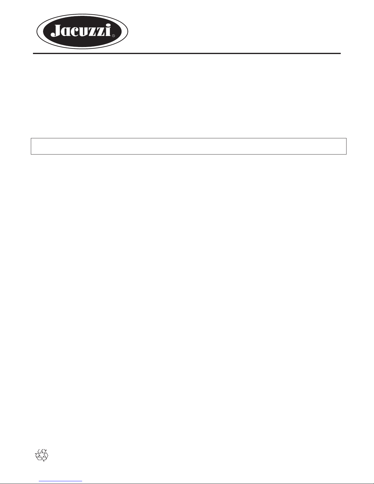
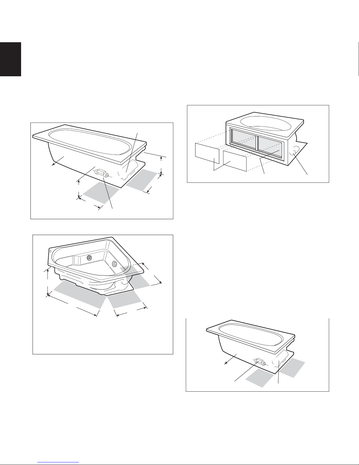
RECTANGULAR BATHS
L
(Heater)
2"
(51 mm)
W
H
L
(Heater)
(25 mm)
1"
W
H
ENGLISH
SIDE VIEW
(Motor)
PLUS BATHS WITHOUT INTEGRAL SKIRT
SPECIFICATIONS (Rectangular)
MODEL
AMIGA™ PLUS
CETRA© 536
PLUS
WITH INTEGRAL
SKIRT
SIGNA© 5 PLUS
SIGNA© 6 PLUS
DIMENSIONS
72" (1829 mm) L*
36" ( 914 mm) W
20-3/4" ( 533 mm) H
60" (1524 mm) L*
36" ( 914 mm) W
21-1/4" ( 553 mm) H
60" (1524 mm) L*
42" (1067 mm) W
22" ( 559 mm) H
72" (1829 mm) L*
42" (1067 mm) W
22" ( 559 mm) H
DRAIN/OVERFLOW
16-7/8" (429 mm) A
14" (356 mm) B
9" ( 229 mm) B
17-1/2" (445 mm) A
12-1/2" (318 mm) B
16-7/8" (429 mm) A
14" (356 mm) B
END VIEW
DIMENSIONS
SIDE VIEW
(Motor)
END VIEW
PLUS BATHS WITH INTEGRAL SKIRT
A
B
DRAIN/OVERFLOW
2
2
2
2
OPERATING
GALLONAGE
50 U.S. gal
(186 liters)
48 U.S. gal
(181 liters)
42 U.S. gal
(159 liters)
55 U.S. gal
(208 liters)
PRODUCT
WEIGHT
105 lb
(48 kg)
92 lb
(42 kg)
108 lb
(49 kg)
118 lb
(54 kg)
SKIRT &
MOUNTING
Optional,
U-Frame
IntegralNA18-1/2" ( 470 mm) A
Optional,
U-Frame
Not
Available
HEATER
Factory Installed
(S750000 HEATER KIT)
Factory Installed
(S750000 HEATER KIT)
Factory Installed
(S750000 HEATER KIT)
(S750000 HEATER KIT)
CUTOUT
70" x 34"
58" x 40"
70" x 40" Factory Installed
TOTAL WEIGHT/
FLOOR LOADING
772 lb
(351 kg)/
43 lb/ft
(210 kg/m2)
742 lb
(337 kg)/
50 lb/ft
(244 kg/m2)
708 lb
(321 kg)/
40 lb/ft
(195 kg/m2)
826 lb
(375 kg)/
39 lb/ft
(190 kg/m2)
*Add 1/4" to this dimension when roughing-in for 3-wall niche.
NOTE: The overall dimensions are nominal with a tolerance of +0 and -1/4".
FOR ALL UNITS: Electrical Service Requirements: All require a dedicated GFCI protected separate circuit.
RapidHeatTM: 120 VAC, 15 AMP, 60 Hz. dedicated GFCI protected separate circuit.
Motor/Pump: 120 VAC, 15 AMP, 60 Hz. dedicated GFCI protected separate circuit.
1
Jacuzzi Whirlpool Bath
©
BP43000 2/05
Page 8
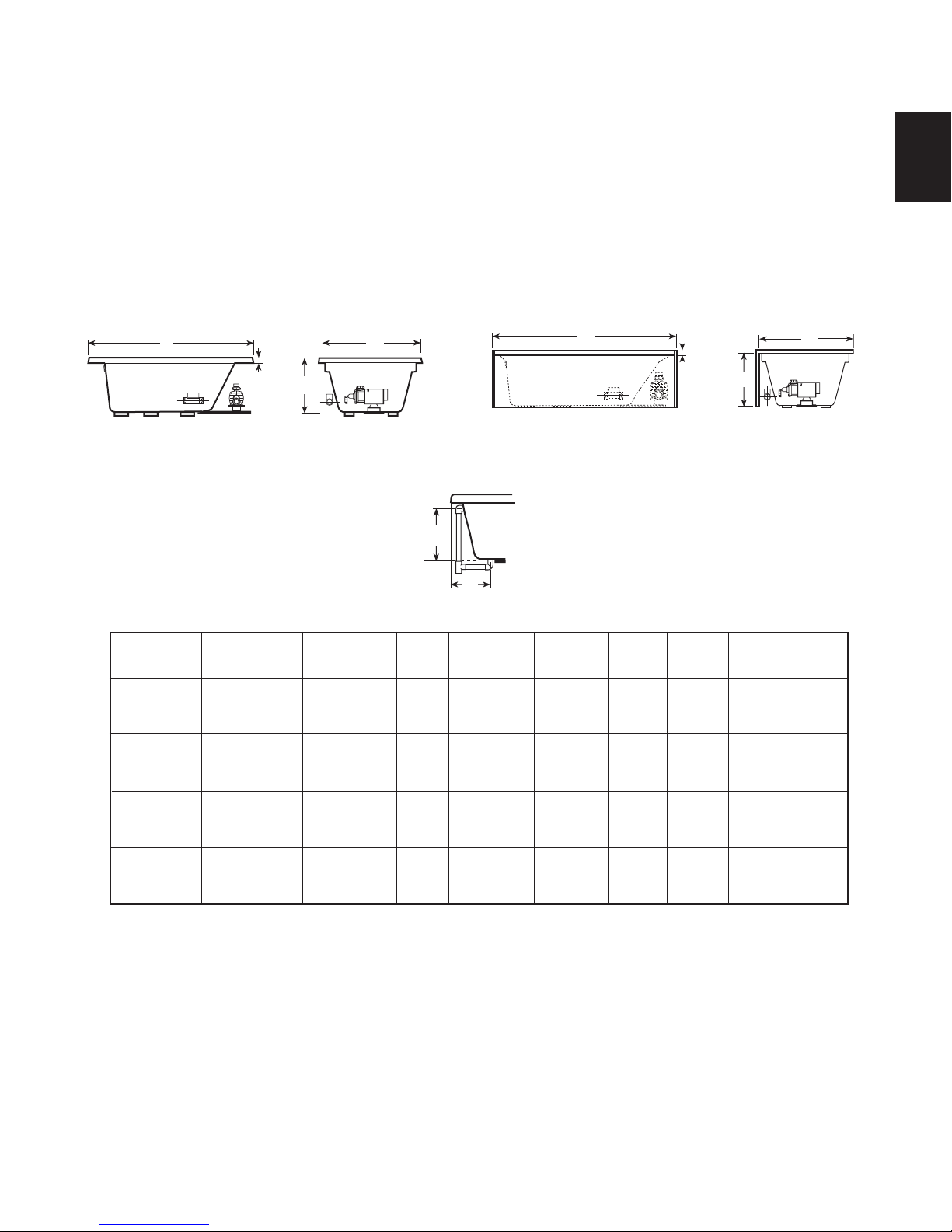
RIMLESS OVAL BATHS
ENGLISH
L
W
2"
(Heater)
SIDE VIEW
(51 mm)
(Motor)
LUNA PLUS
H
END VIEW
A
B
DRAIN/OVERFLOW
SPECIFICATIONS (Oval)
MODEL
LUNA™ PLUS
DIMENSIONS
72" (1829 mm) L
42" (1118 mm) W
23" ( 584 mm) H
DRAIN/OVERFLOW
DIMENSIONS
19-1/8" (486 mm) A
11" (279 mm) B
CUTOUT
Template
Provided
P/N
P819000
TOTAL WEIGHT/
FLOOR LOADING
1176 lb
(535 kg)/
2
56 lb/ft
(273 kg/m2)
OPERATING
GALLONAGE
96 U.S. gal
(364 liters)
PRODUCT
WEIGHT
126 lb
(57 kg)
NOTE: The overall dimensions are nominal with a tolerance of +0 and -1/4".
FOR ALL UNITS: Electrical Service Requirements: All require a dedicated GFCI protected separate circuit.
RapidHeatTM: 120 VAC, 15 AMP, 60 Hz. dedicated GFCI protected separate circuit.
Motor/Pump: 120 VAC, 15 Amp, 60 Hz. dedicated GFCI protected separate circuit.
SKIRT &
MOUNTING
Not
Available
HEATER
Factory Installed
(S750000 HEATER KIT)
CORNER BATHS
L
2"
(51 mm)
SIDE VIEW
(Heater)
H
(Motor)
TARA PLUS CORNER BATH
END VIEW
SPECIFICATIONS (Corner)
PRODUCT
WEIGHT
118 lb
(54 kg)
2
OPERATING
GALLONAGE
74 U.S. gal
(280 liters)
MODEL
TARA™ PLUS 16" (406 mm) A
DIMENSIONS
60" (1524 mm) L
60" (1524 mm) L
20-3/4" ( 527 mm) H
DRAIN/OVERFLOW
DIMENSIONS
12-3/8" (314 mm) B
CUTOUT
Page 3
TOTAL WEIGHT/
FLOOR LOADING
984 lb
(447 kg)/
39 lb/ft
(190 kg/m2)
NOTE: The overall dimensions are nominal with a tolerance of +0 and -1/4".
FOR ALL UNITS: Electrical Service Requirements: All require a dedicated GFCI protected separate circuit.
RapidHeatTM: 120 VAC, 15 AMP, 60 Hz. dedicated GFCI protected separate circuit.
Motor/Pump: 120 VAC, 15 Amp, 60 Hz. dedicated GFCI protected separate circuit.
A
B
DRAIN/OVERFLOW
SKIRT &
MOUNTING
OptionalSee
Factory Installed
(S750000 HEATER KIT)
HEATER
Jacuzzi Whirlpool Bath
©
BP43000 2/05
2
Page 9
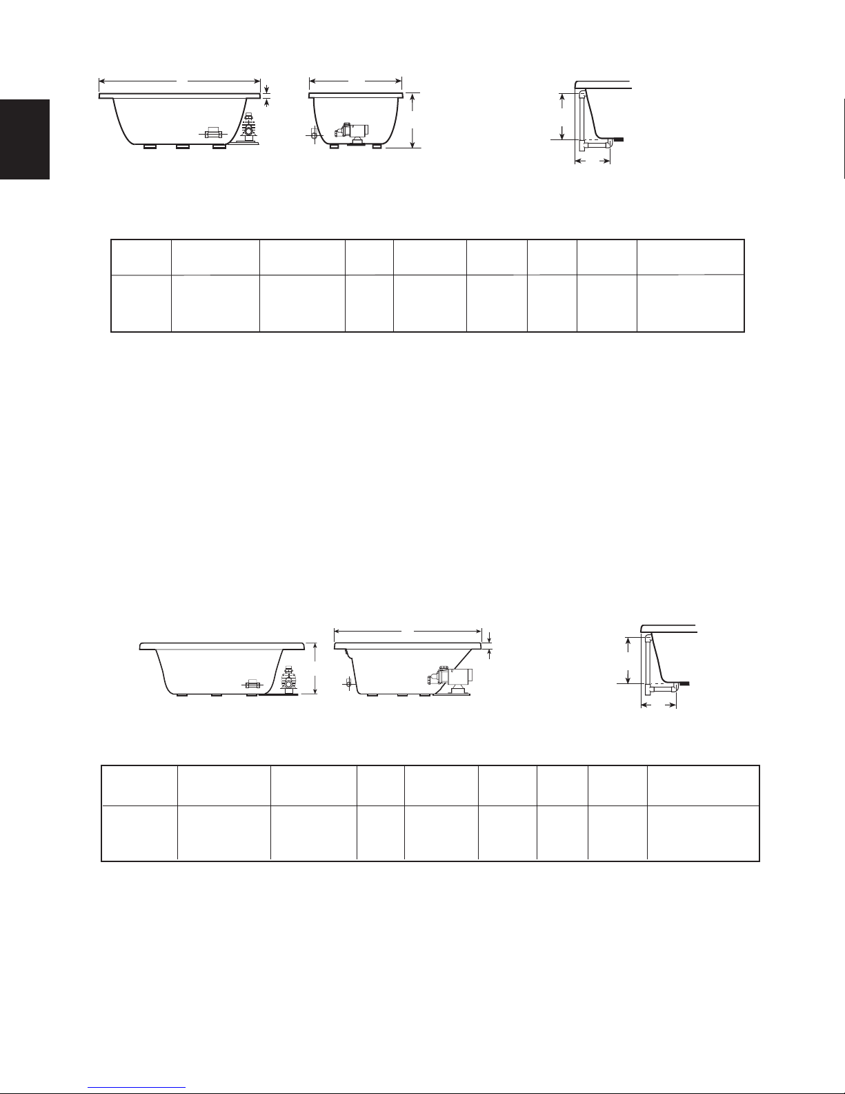
ROUGHING-IN REFERENCE (RECTANGULAR)
T
"
SUPPORT FOR CORNER BATHS
H
2" x 4" STUD
APPLY
ADHESIVE
)
Note: 1. Baths shown are left-hand unless otherwise specified. Right-hand is a mirror image.
2. Some units have been provided with cutout templates included in shipping carton.
See CUTOUT information for each model on page 1 and 2.
3. THE OVERALL DIMENSIONS ARE NOMINAL WITH A TOLERANCE OF +0 AND -1/4".
4. Measurements inside each unit represent cutout in floor to allow for drain/overflow.
5. All measurements are in inches. To convert to millimeters, multiply inches by 25.4.
72''
ENGLISH
*60"
18''
16'' x 4''*
36''
2''
14''
(Left hand only)
AMIGA PLUS
60"
42"
13" x 5"
5"
12
4-1/4"
30"
(Right hand only.)
SIGNA 5 PLUS
*Add 1/4" to this dimension when roughing-in for 3-wall niche.
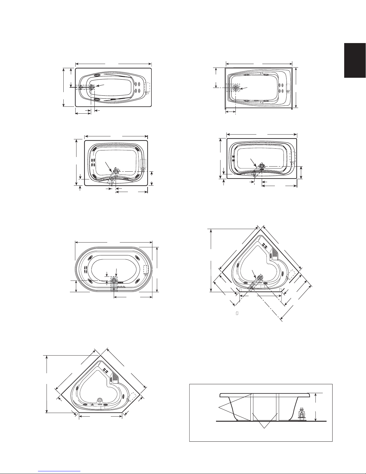
ROUGHING-IN REFERENCE (OV AL AND CORNER)
72"
13" X 6"*
3"
42"
17-3/8"
12" x 4"*
9"
(Left hand shown. Right hand is mirror image.)
CETRA 536 PLUS WITH INTEGRAL SKIR
72"
11 -
1/4"
18-1/2" x 5"*
42"
5"
(Right hand only.)
SIGNA 6 PLUS
61-5/8"
Ref.
60"
14" x 4"*
36"
12-1/2"
36"
60"
11"
(Right-hand only.)
LUNA PLUS
CUTOUT- CORNER BATH
58"
(1473 mm)
59"
Ref.
25-1/2"
(648 mm)
45-9/16"
(1157 mm)
CUTOUT
TARA PLUS
(1473 mm)
36"
58"
(648 mm
25-1/2"
27-1/4"
35"
46"
27-1/4"
35"
44"
- 2" x 4" Stud
(Right hand only)
TARA PLUS
Corner Baths with Skirt
If an optional skirt is used on a corner bath, additional support is
necessary in the front of the unit. Measure the height from the floor
to the underside of the bath rim. Cut two 2" x 4" studs, apply adhesive to both ends and install.
3
Jacuzzi Whirlpool Bath
©
BP43000 2/05
Page 10
Framing and Support
The drain/overflow of the bath extends below the bottom of the bath. Note that this requires a cutout in the floor.
The floor structure beneath the bath must be able to support a total weight of bath, water , and bather. Refer to the table under tot al
weight for your model. The unit must be supported from the bottom of the bath and not from the bath rim or tile flange. If the subfloor is level
and a continuous surface, no other preparation is necessary . You can proceed to install the bath. If the subfloor is not level, you MUST level the
entire surface prior to installing the bath. The use of materials that shim or provide a level installation are allowed provided the method used will
insure a level bath that is supported from the bottom. Materials that may be used are a floor leveling compound, mortar, plaster or minimal
expansion structural foam having a density of a minimum of 5 lbs./cubic ft.; however the bath must remain level in order for it to drain properly
and all foam feet must make full contact with the leveling material. Both sides of a joint or splice of subfloor should be level to each other. When
ENGLISH
attaching baths with flanges to stud wall, use shims to fill any gaps between the bath flange and studs.
The rim of the bath is not designed to support weight. If finish material is to overlap or contact the bath, the added weight must be fully self-
supporting.
The protective film liner inside the bath is used to prevent damage to the finish during installation. Before installation, remove
liner to inspect for any defects, reapply and do not remove until final cleanup.
Important: If a skirt is to be used, it must be installed at the time of unit installation – refer to skirt installation instructions. Install
optional trim parts when all installation has been completed.
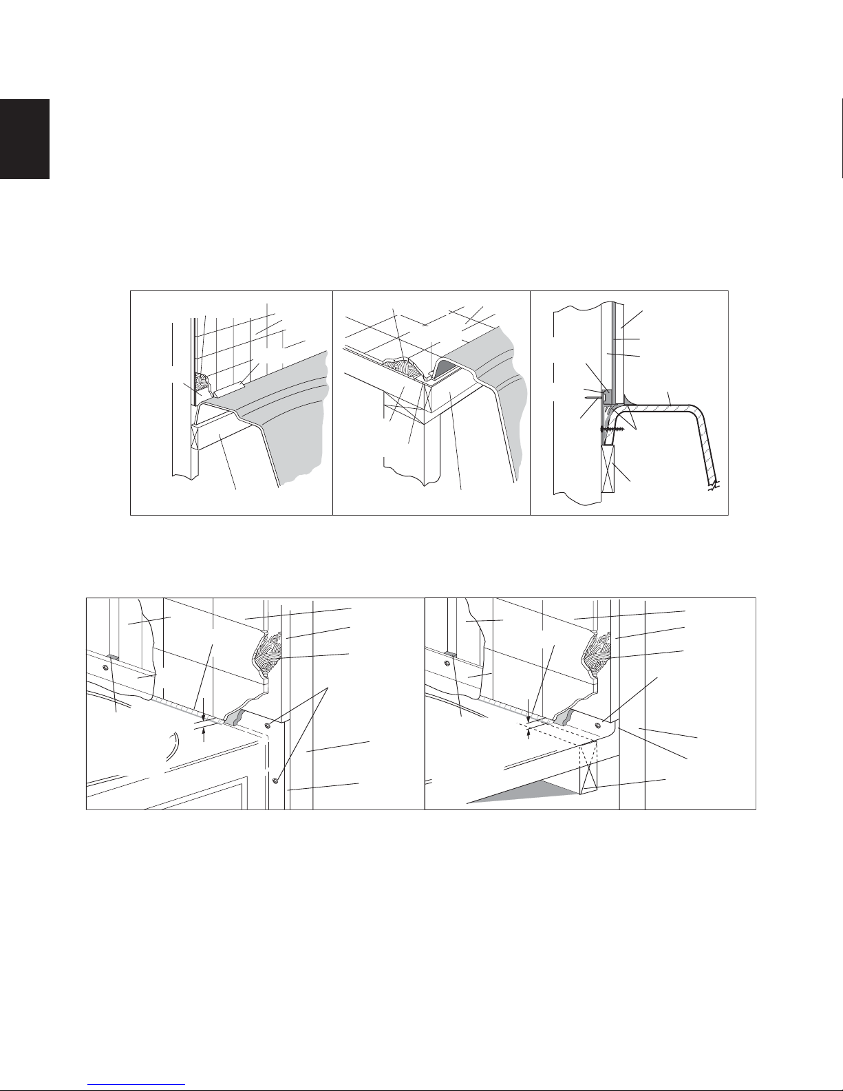
TYPICAL INSTALLATIONS
MORTAR OR ADHESIVE
FLASHING
TILE
MORTAR OR ADHESIVE
SEALANT
SEALANT
TILE
PLASTER
FILLER
FLANGE
FINISHING
MATERIAL
MORTAR
CEMENT
BOARD
BATH RIM
1" X 4" (NOT FOR SUPPORT)
FLUSH TO WALL
TYPICAL FLANGE MOUNTING DETAIL
STUD
CAULKING
FLANGE
SHIM IF
NECESSARY
TO FILL GAPS
BETWEEN
STUD
AND FLANGE
1/8" GAP
SUB-FLOOR
FLASHING
1" X 4" (NOT FOR SUPPORT)
SEMI-SUNKEN
TILE
CEMENT
BOARD
TILE
ADHESIVE
ATTACH WITH
SCREWS
PROVIDED
STUD
FLANGE
SHIM IF
NECESSARY
TO FILL GAPS
BETWEEN
STUD
AND FLANGE
STUD
FLANGE
1/8" GAP
NAIL
OR
SCREW
STUD
WALL
1" X 4" (NOT FOR
SUPPORT)
OPTIONAL TILE FLANGE KIT
CAULKING
SILICONE
SEALANT
ATTACH WITH
SCREWS
PROVIDED
1"X 4"
(NOT FOR
SUPPORT)
TILE
CEMENT
BOARD
TILE
ADHESIVE
STUD
FLANGE
Jacuzzi Whirlpool Bath
©
BP43000 2/05
4
Page 11
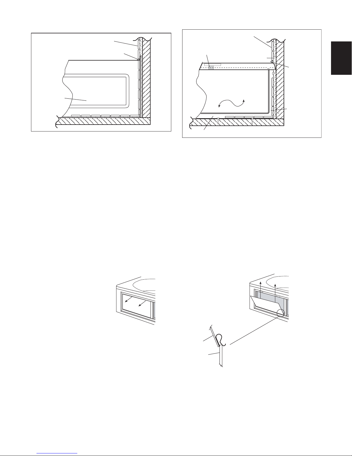
Skirts
INTEGRAL SKIRT MOUNTING DETAIL
FINISHING
MATERIALS
CAULKING BEAD
U FRAME SKIRT MOUNTING DETAIL
FINISHING MATERIALS
SECURE SHELL CLIP
UNDER CENTER
BATH RIM
FILLER (Optional)
ENGLISH
CAULKING
BEAD
SKIRT
PAN E L
SECURE BOTTOM OF FRAME TO FLOOR
SKIRT
PANEL
SKIRT
FRAME
Removable Skirt Panel
To remove panel, grab the top of access panel and pull outward to release Velcro™. Then pull access panel
upward to release holding clips.
To reinstall, engage holding clips onto skirt and then push panel forward to reengage Velcro™.
PULL OUTWARD
FROM TOP TO
RELEASE VELCRO™
ACCESS
5
PULL UPWARD
TO RELEASE CLIPS
PAN E L
SKIRT
Jacuzzi Whirlpool Bath
©
BP43000 2/05
Page 12
MOTOR
AREA
A
AREA
B
FRONT
HEATER
Service Access
For partially or fully sunken installations, allow for access to service connections. It is the installer's responsibility to provide sufficient service access. The recommended minimum dimensions allowable for service to the bath are shown in the "Service Access"
illustration.
Provide adequate area around unit for air circulation for cooling
the motor and to supply sufficient air to the jets. Do not insulate this
area or around motor.
ENGLISH
RapidHeatTM Service Access
Comfort Plus tubs come with a factory installed RapidHeat
heater and you may consider an additional service access.
If service access has not been provided, it is the home owners
responsibility to remove the bath and provide the required
access, should a repair become necessary.
SERVICE ACCESS
(WITHOUT SKIRT)
MOTOR
Service Access with Skirt
An optional skirt fits along the side of the bath for above-floor
installations and is also an access panel for servicing. Allow a space
of at least 8 inches away from the bath for skirt removal.
The skirt is designed to accommodate the added height of the
tile, linoleum, or other floor coverings up to 1-1/4 inches above the
floor, and will be flush with the floor when installed.
More detailed instructions on skirt installation are provided with
the optional skirt assembly.
TM
Service Access with Integral Skirt
Service access is through the removable skirt panels.
SERVICE ACCESS
(WITH INTEGRAL SKIRT)
FRONT
12"
ALTERNATE
ACCESS
SERVICE ACCESS
18"
RIGHT HAND UNIT SHOWN
A - Preferred access
B - Acceptable alternative if access A is not possible
C - Optional access for equipment
NOTE: Left hand unit access is on the opposite
side (mirror Image).
18"
HEATER
(CORNER BATHS)
C
36"
A
PREFERRED
ACCESS
B
24"
20"
18"
12"
REMOVABLE SKIRT
ACCESS PANELS
In some cases, access may not have been provided because of
the design of the bath environment and having full understanding
that in this case, it may be necessary to remove the unit for service.
If this is the case, diagnosing a problem may not be possible
without complete access to the plumbing system. This would necessitate the removal of the unit. Although this practice is not commonly implemented, it is an acceptable method.
ACCESS AREA
MOTOR
©
Jacuzzi Whirlpool Bath
BP43000 2/05
In some cases access may have been provided in Area A but
service is required in Area B which requires the unit to be pulled for
service and reinstalled.
If service access has not been provided, it is the home owners
responsibility to remove the bath and provide the required
access, should a repair become necessary.
6
Page 13
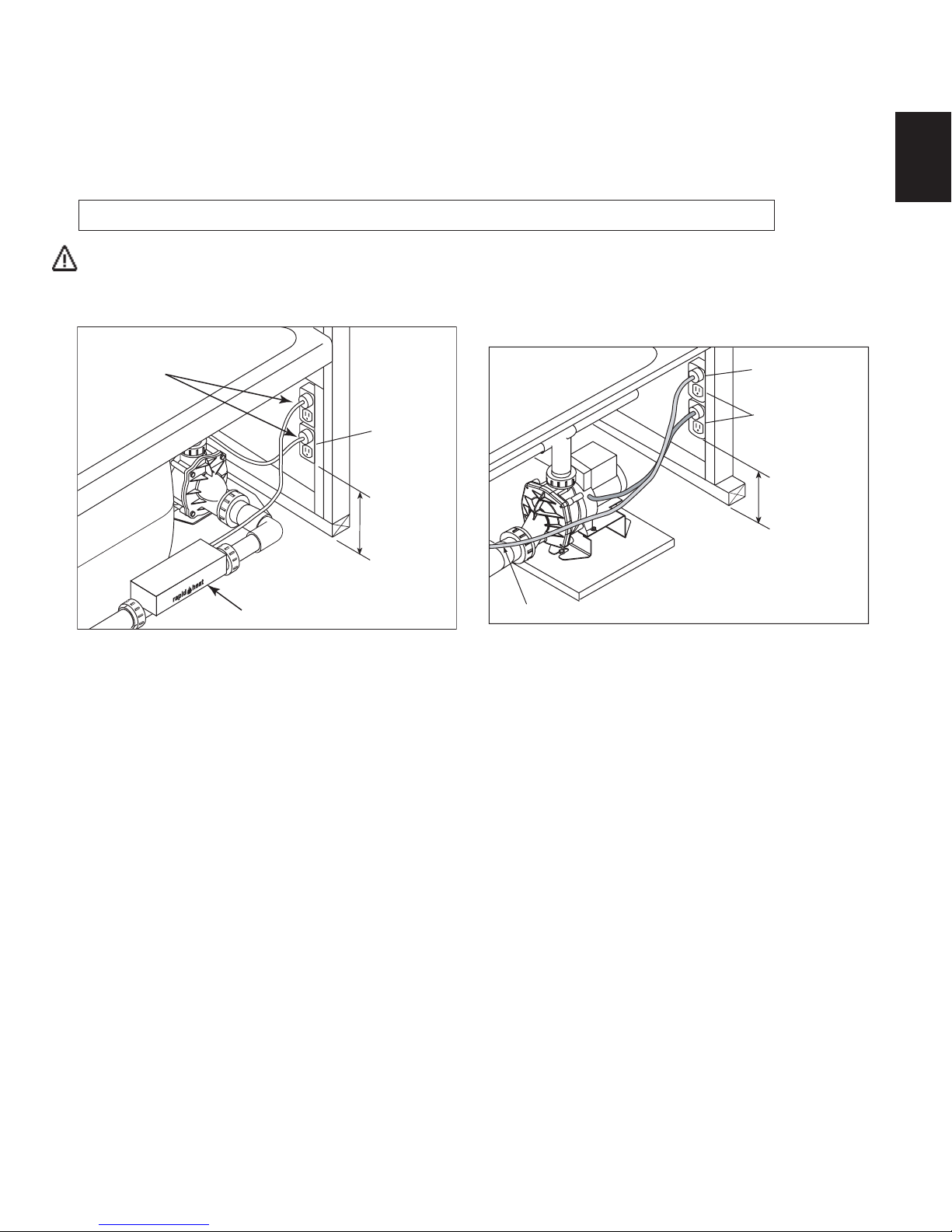
Electrical Connections
Two separate 120 VAC, 15 AMP circuits, which must be protected by a Ground Fault Circuit Interrupter (GFCI), are required. Install duplex
outlets to the studwall underneath the bathtub, at least 4 inches above the floor. The duplex outlets are not provided. One circuit is for the
pump/motor and the other is for the RapidHeatTM heater.
Install a separate 120 VAC, 15 AMP dedicated circuit with GFCI protection. With a #8 solid copper wire, bond the heater to the house
electrical panel or approved local bond. A bonding lug is provided on the heater.
At initial start-up and before each use thereafter with power ON, push the GFCI test button. The reset button should pop out. Push this
button in to reset. If the interrupter fails to operate in this manner, there is a ground current flowing or a device malfunction, indicating the
possibility of electrical shock. Turn off power and do not use the bath until the source of the problem has been identified and corrected.
DANGER: RISK OF ELECTRIC SHOCK. Connect only to a circuit protected by a Ground Fault Circuit Interrupter.
CAUTION: Operating the motor/pump without enough water in the bath can cause leaking and permanent damage to the pump and/
or heater. Before power is applied to the installation, make sure the switch is in the OFF position to avoid pump damage.
ELECTRICAL CONNECTION WITH RAPIDHEAT
INSTALL SEPARATE
ELECTRICAL CONNECTION
GFCI PROTECTED CIRCUITS
(FOR CORNER BATHS)
EACH HAS 3
PRONG PLUG
ENGLISH
DUPLEX
RECEPT.*
DUPLEX
RECEPT.*
4" MIN.
4" MIN.
OR IN
ACCORDANCE
WITH LOCAL
BUILDING OR
ELECTRICAL
CODES
M
T
HEATER
*(NOT PROVIDED)
TO HEATER
FLOOR
OR IN
ACCORDANCE
WITH LOCAL
BUILDING OR
ELECTRICAL
CODES
*(NOT PROVIDED)
7
Jacuzzi Whirlpool Bath
©
BP43000 2/05
Page 14

Plumbing and Water Supply
Drain Information
A drain/overflow assembly (sold separately) must be installed on the bath, water tested, and connected to the sanitary system of the house.
After opening the carton, inspect for damage and verify that the kit is of the proper finish. In the Jacuzzi Whirlpool Bath© drain/overflow kit, note
that the waste flange, strainer, overflow cover and cover screws are packaged in a separate package within the kit to protect the trim finish.
Follow the installation instructions provided with your drain/overflow kit. After the drain is fully inst alled, test for proper drainage. If the unit does
not drain properly, rectify this condition before proceeding with the installation. Jacuzzi Whirlpool Bath© is not responsible for removal and or
ENGLISH
reinstallation costs.
NOTE: Watertight installation of the drain is the installer's responsibility. Drain leakage is excluded from the Jacuzzi Whirlpool
Bath© warranty of this product.
Plumbing
Pump, jets, and suction fittings for the whirlpool system are factory plumbed in Schedule 40 PVC piping.
All Jacuzzi Whirlpool Bath
detected, notify Jacuzzi Whirlpool Bath. Do not install the unit.
Water Supply
Consult local authorities for plumbing code requirements in your area.
IMPORTANT: Proper installation of the fill spout plumbing and compliance with local codes are the responsibility of the installer.
Jacuzzi Whirlpool Bath© does not warrant connections of water supply fittings and piping, fill systems, or drain/overflow systems.
Nor is it responsible for damage to the bath which occurs during installation.
CAUTION: A nonflammable protective barrier must be placed between soldering work and bath unit to prevent damage to the bath.
©
products are factory tested for proper operation and watertight connections prior to shipping. If leaks are
Clean-Up After Installation
To avoid dulling and scratching the surface of the bath, never use abrasive cleaners. A mild liquid detergent and warm water will clean
soiled surfaces.
Remove spilled plaster with a wood or plastic edge. Metal tools will scratch the surface. Spots left by plaster or grout can be removed if
lightly rubbed with detergent on a damp cloth or sponge.
Major scratches and gouges which penetrate the acrylic surface will require refinishing. Contact your Jacuzzi Whirlpool Bath© dealer for
special instructions.
Jacuzzi Whirlpool Bath
©
BP43000 2/05
8
Page 15

OPERA TING INSTRUCTIONS
101
101
Operation
Note: These instructions pertain to all bath products manufactured by Jacuzzi Whirlpool Bath. Not all features discussed in
this instruction pamphlet apply to all baths.
All baths manufactured by Jacuzzi Whirlpool Bath
for "fill and drain," which means the bath should be drained after
each use and filled with fresh water by the next bather. This is a
health precaution, as these baths are not designed to hold water
continuously like pools or spas.
LED DISPLAY
©
are designed
101
ON/OFF
PUMP MOTOR
Control Panel
Comfort Plus With Light System
The Comfort Plus With Light System control panel, located on the
bath, allows you to control the pump, observe the water temperature,
and control the Chromotherapy lighting system while in the bath.
During operation the system displays water temperature allowing for
an approximate temperature fill. The Chromotherapy lighting system
controls the 2 Channel Chromotherapy lamps where you can turn on
bath lighting in white, a color of choice, or a continuous flow through
all colors. The system (pump, heater, and display) automatically
shuts off after 30 minutes of operation, the Chromotherapy lighting
system has a 4 hour lamp timeout. To restart the system (pump,
heater, and display) simply press the ON/OFF button again.
CAUTION: Temperature sensors and values are approximate and
may vary. Use caution when entering heated water.
On/Off Pump/Motor
Pressing this button will turn ON the pump/motor. Pressing a second time will turn OFF the pump/motor.
Bath Light ON/OFF
Pressing this button will turn ON the bath light(s). The light(s) will
come ON displaying the White colored light. Pressing a second
time will turn all light(s) OFF. (Use the "Light Color Cycle" button to
turn ON the color lights.)
Light Color Cycle
Pressing this button will turn ON the colored light(s) to the "favorite"
light (default is blue). Pressing this button again will begin the light(s)
cycling through each of the available colors. This will continue until
the Light Color Cycle button is pushed again, which stops the light
cycling action on the current color. Press the button again and you
will begin the Light Color Cycle again.
To create a new “favorite” color: Allow the lights to rotate to the new
"favorite" light color. Stop the cycling on that color. Press and hold
down the button for three seconds (the light will then blink to confirm
the new "favorite").
LED Display
The Comfort Plus control panel water temperature displays when
the water level covers the internal water sensor even if the Comfort
Plus With Light System controls are not turned ON. This feature is
designed to give a temperature indication even if the whirlpool system
is not being used.
Pressing and holding the ON/OFF button for three (3) seconds
displays a "time remaining" minute countdown. After displaying the
"time remaining" countdown for 30 seconds, the readout reverts back
to the temperature display.
LIGHT COLOR CYCLE
BATH LIGHT ON/OFF
LED DISPLAY
101
ON/OFF
PUMP MOTOR
Control Panel
Comfort Plus No Light System
The Comfort Plus control panel, located on the bath, allows you to
control the pump and observe the water temperature
bath. During operation the system displays water temperature
allowing for an approximate temperature fill. The system (pump,
heater, and display) automatically shuts off after 30 minutes of
operation. To restart simply press the ON/OFF button again.
CAUTION: Temperature sensors and values are approximate and
may vary. Use caution when entering heated water.
On/Off Pump/Motor
Pressing this button will turn ON the pump/motor. Pressing a second time will turn OFF the pump/motor.
LED Display
The Comfort Plus control panel water temperature displays when
the water level covers the internal water sensor even if the Comfort
Plus No Light System controls are not turned ON. This feature is
designed to give a temperature indication even if the whirlpool system
is not being used.
Pressing and holding the ON/OFF button for three (3) seconds
displays a "time remaining" minute countdown. After displaying the
"time remaining" countdown for 30 seconds, the readout reverts back
to the temperature display.
Water Level
Close the drain and fill the bath until water is at least 1" above the
highest jet (see water line indicated in the illustration). Do not turn
on the whirlpool system at any time if the jets are not completely
immersed in water. Running the whirlpool system when there is
insufficient water in the bath could result in water spraying outside
the bath area. Running the whirlpool system without water will damage the recirculating pump.
Do not immerse the control panel by overfilling the bath.
FILL TO AT LEAST
1" ABOVE HIGHEST JET
while in the
1"
ENGLISH
9
Jacuzzi Whirlpool Bath
©
BP43000 2/05
Page 16

Controlling Whirlpool Action
T
WATER RAINBOW
FILL SPOUT (OPTIONAL)
COMFORT PLUS
ON/OFF SWITCH
AIR CONTROL
KNOBS
DRAIN/OVERFLOW
(OPTIONAL)
FULLY ADJUSTABLE JETS
TYPICAL BATH FITTINGS
SUCTION
COVER
The whirlpool action in your bath is influenced by three factors –
direction of flow, force of water, and force of air. All whirlpool baths
manufactured by Jacuzzi Whirlpool Bath© are equipped with adjustable PowerPro® jets, that may be adjustable for one or more of the
three factors.
Direction: To change the direction of the water flow, swivel the
jet nozzle to the desired angle. The jets can be directed individually
ENGLISH
toward any location on your body to provide a hydromassage. The
jets can also be adjusted so that they all point in the same direction
(clockwise or counterclockwise) to circulate the water in a circular
motion around the bath, causing a total whirlpool effect.
Water Force: The high volume, fully adjustable jets can be adjusted to control the force of the water coming into the bath. For
robust action, increase the force of the flow by rotating the jet handles
to the left (counterclockwise). For a more gentle effect, rotate the
handles to the right (clockwise). Never run the whirlpool system
with all the jets closed.
Force of Air: Two knobs located on the bath serve as controls
for the air induction system. The intensity of the hydromassage whirlpool action is determined by the amount of air inducted into the water. As the amount of air is increased, the hydromassage action
increases. For maximum air induction, rotate the control knobs fully
counterclockwise to the largest circles. For fewer air bubbles, decrease the amount of air induction by rotating the control knob clockwise. When the knobs are turned to the smallest circles, only water
is being circulated.
JETS
DIRECTIONALLY
ADJUSTABLE
AIR INDUCTION CONTROLS
URN CLOCKWISE TO
REDUCE AIR FLOW
FULLY
ADJUSTABLE
TURN COUNTER-CLOCKWISE
TO INCREASE AIR FLOW
RapidHeatTM Operation
Once the heater is installed and the whirlpool pump is operating,
the heating function is totally automatic. The heater will help maintain the temperature of the water in the bath.
Vacuum Switch
The heater is equipped with a preset vacuum switch which will
not allow the heater to turn ON if the pump is not running with water
flowing through the whirlpool system.
High-Limit Switch
The heater includes an exclusive High-Limit switch. This safety
circuit will not false trip from hot tap water. It will only turn off the
heater if the thermostat fails. To reset, press the button. If the highlimit trips frequently, contact your Authorized Electrical/Mechanical
Service Provider. Visit our web site at http://www.jacuzzi.com/ to
find a Service Provider.
Jacuzzi Whirlpool Bath
©
BP43000 2/05
10
HIGH LIMIT RESET
OVER HEAT
PROTECTION
PUSH TO RESET
HEATER ON
HEATER ON
Page 17

MAINTENANCE INSTRUCTIONS
Cleaning the Bath
To clean your bath, simply use a mild, nonabrasive liquid detergent solution. You can protect and restore the gloss to a dulled
acrylic surface by applying an acrylic polish or automotive paste wax.
Never use abrasive household cleaners on any Jacuzzi Whirlpool Bath© product.
Repairs to the Surface
Major scratches and gouges which penetrate the acrylic surface
will require refinishing. Contact your Jacuzzi Whirlpool Bath© dealer
for special instructions.
Purging the Whirlpool System
NOTE: THE WHIRLPOOL SYSTEM SHOULD BE PURGED AT
LEAST TWICE A MONTH
To remove accumulations of bath residue from the whirlpool system,
it is recommended that the whirlpool bath be purged at least twice a
month. For best results, however, we recommend that you purge your
whirlpool bath after each use using our exclusive two-part plumbing
system cleaner made specifically for whirlpool baths.
Systems Clean ™ i s available through an authorized Jacuzzi Whirlpool Bath© Distributor or by calling us direct at 1-800-288-4002.
Instructions for use: Immediately after bathing and exiting the
whirlpool bath, leave the bath water in the tub and add hot water, if
necessary, so the water is at least 1" above the highest jet. Turn on
the unit without the aerator. Pour the contents of the Systems Clean
Packet 1 (taking care not to get the material on yourself) into the bath
near the intake for the circulation pump. Repeat same process with
Systems Clean Packet 2. It is important to use Packet 1 before
Packet 2 to avoid a strong odor. Run the bath for 5 to 10 minutes.
Drain completely and rinse any residue.
If you have followed the standard purging instructions above and still
have an excess accumulation of bath residue and desire an alternative cleaning mechanism, we recommend SUPER SYSTEMS CLEAN
PLUS manufactured by Stearns Packaging to rectify this condition.
This may be obtained by contacting us at l-800-288-4002. It is
recommended that you follow the instructions provided by the manufacturer with the product. Repeated use may be necessary. SUPER
SYSTEMS CLEAN PLUS does not replace the necessity to regularly
purge your whirlpool system with Systems Clean as recommended.
(For additional information about water content, contact us for a copy
of the Jacuzzi Water Quality Primer.)
Suction Cover/Strainer Maintenance
Clean the suction cover/strainer of hair and debris when necessary. To do this, remove the center screw and detach the square
cover. Clean the cover by backflushing debris from the holes. Replace the suction cover immediately after cleaning. When reinstalling, orient the cover/strainer with the small notch at the bottom. The
gasket must be inserted into the groove of the cover/strainer before
reinstalling onto the suction fitting.
CAUTION: Keep hair a minimum of 6 inches away from the suction fitting at all times when the whirlpool system is operating.
Hair longer than shoulder length should be secured close to
the head, or a bathing cap should be worn. Do not operate the
whirlpool system with the suction cover removed! It is a safety
device and must always be in place on the suction fitting to
minimize the potential hazard of hair and body entrapment.
SUCTION COVER/STRAINER ASSEMBLY
COVER STRAINER
SUCTION
FITTING
SCREW
NOTCH
GASKET
Lamp
If your unit has chromotherapy lighting and the lights fail to function contact your Jacuzzi Whirlpool Bath© dealer. There are no customer serviceable components on the chromotherapy lighting. You
may also visit our web site at http://www.jacuzzi.com/ to find the near-
est authorized service agent listing for your Jacuzzi Comfort Plus tub.
LED LIGHT ASSEMBLY
ENGLISH
Bath Additives
NOTE: DO NOT USE OIL OR OIL BASED BATH ADDITIVES.
If you want to use any kind of bath additive, use only a small amount
of low-foaming powder or crystal substance; the whirlpool action
intensifies the foaming properties of soaps.
The use of certain bath oils, bubble baths and bath additives may
increase the level of accumulations of bath residue in the whirlpool
system. If excess accumulations persist, you should discontinue use
of these products.
11
LOCKING NUT
Jacuzzi Whirlpool Bath
LIGHT BEZEL
SHELL
©
BP43000 2/05
Page 18

General Whirlpool Bath Troubleshooting Guide
PROBABLE CAUSES PROBLEM REMEDY
Pump/Motor does not start.
ENGLISH
Pump/Motor operates but no fully
adjustable jets are functioning.
Pump/Motor operates but air is not
injected into water.
Pump/motor does not shutoff.
Water leakage from pump unions.
No power to pump/motor.
Pump/motor not plugged in.
Magic Touch switch - air tube not
connected to switch or to air switch
on pump/motor.
Pump/motor faulty.
Jets are closed.
Suction cover may be clogged.
Air valves closed.
If a wall timer is used, the timer is
defective
Overtightened, O-ring may be
pinched or improperly seated, under
tightened.
Reset GFCI.
Insert plug fully into outlet.
Reconnect tube to Magic Touch switch
or to air switch pump/motor.
Replace pump/motor assembly.
Open jets by rotating counterclockwise.
With motor turned off, remove safety
cover and remove any debris. Replace
suction cover before operating.
Open air control valves.
Replace timer.
Untighten unions check and reseat Oring. If O-ring has been pinched out of
shape, replace (refer to Service Support
number below). When tightening union
nuts, hand tighten only.
Pump/motor shuts off by itself or with
wall timer, before set time elapses.
Motor thermal protection has
deactivated pump/motor due to
overheating. (Supply voltage low.)
GFCI tripped.
Let motor cool; thermal protection will
reset. Check for proper ventilation.
(Check supply voltage.)
Reset GFCI. If it continues to trip do not
use this unit. Disconnect the unit and
have the problem corrected by a
licensed electrician before using.
Inadequate supply wiring.
Consult a licensed electrician to correct
wiring to unit.
Chromotherapy lights fail to operate.
Fiber-optic connector has come
loose.
Consult the nearest Jacuzzi authorized service
agent.
NOTE: If unit is within the warranty period, contact Jacuzzi Whirlpool Bath© Service Support at 1- (800)- 288-4002 with bath's
serial number before work is started. The Serial Number is located on the Specification/Serial Number Plate. See page 14.
Jacuzzi Whirlpool Bath
©
BP43000 2/05
12
Page 19

ENGLISH
r
PRODUCT SPECIFICATIONS ARE SUBJECT TO CHANGE WITHOUT NOTICE.
USE INSTALLATION INSTRUCTIONS SUPPLIED WITH PRODUCT.
Jacuzzi Whirlpool Bath© has obtained applicable code (standards) listings generally available on a national basis for products of
this type. It is the responsibility of the installer/owner to determine specific local code compliance prior to installation of the product.
Jacuzzi Whirlpool Bath
Printed on Recycled Pape
©
makes no representation or warranty regarding, and will not be responsible for any code compliance.
©
2005 Jacuzzi Whirlpool Bath
Jacuzzi Whirlpool Bath
©
P.O. Box 702168, Dallas, TX 75370-2168
Service Support: (800) 288-4002
©
BP43000 2/05
13
Printed in the U.S.A.
Jacuzzi Whirlpool Bath© BP43000 2/05
Page 20

Authorized Service
If you need a referral for a service company near you, or need assistance with operation or maintenance related
questions, please call our Service Support Department at 1-800-288-4002. For service agent listing, visit our web
site at http://www.jacuzzi.com/. To find the service agent listings, click on For The Trade. Then click on Electrical/
Mechanical Service Agents. Depending on the problem, click on Electrical/Mechanical Rep airs or Finish, Surface or
Shell-Related Problems.
ENGLISH
When requesting service or technical assistance please have available both the model and serial number of your
unit. This information can be obtained from the product registration card provided with your unit. If the card has
been misplaced, this information can be obtained from the specification/serial number label on the unit itself (for
location of specification/serial number label see below).
BA TH PRODUCTS
Whirlpool baths: The label is located on the wall of the bath near the pump/motor.
SPECIFICATION/SERIAL NUMBER PLATE
YOU WILL FIND YOUR
SERIAL NUMBER HERE.
MODEL # XXXXXXX
NAME XXXXX
COLOR XXXXX
MFG # XXXXX
SER # XXXXXX
THIS PRODUCT MEETS OR EXCEED
THE FOLLOWING STANDARDS
BATH & SPA ANSI Z124.1
SHOWER BASES ANSI Z124.2
MADE IN
USA
Jacuzzi Whirlpool Bath
©
BP43000 2/05
14
Page 21

ADDENDUM
r
AUTHORIZED SERVICE Change
This sheet replaces the Authorized Service page in this manual.
AUTHORIZED SERVICE
If you need a referral for a service company near you, or need assistance with operation or
maintenance related questions, please call our Service Support Department at 1-800-288-4002.
Visit our web site at http://www.jacuzzi.com/ for products and services.
To find service agent listings for:
Electrical or Mechanical Repairs visit http://jacuzzi.com/pdf/ASA.PDF
Finish, Surface, or Shell-Related Repairs visit http://jacuzzi.com/pdf/AFC.PDF
Repair Parts or Accessories visit http://jacuzzi.com/pdf/MPD.PDF
When requesting service or technical assistance please have available both the model and
serial number of your unit. This information can be obtained from the product registration card
provided with your unit. If the card has been misplaced, this information can be obtained from
the specification/serial number label on the unit itself (for location of specification/serial number label see below).
BATH PRODUCTS
Combination baths: The label is located on the wall of the bath near the pump/motor.
Whirlpool baths: The label is located on the wall of the bath near the pump/motor.
Air Baths: The label is located on the wall of the bath near the blower.
Non-jetted baths: The label is located next to the overflow.
SPECIFICATION/SERIAL NUMBER PLATE
CORE NUMBER - SERIAL NUMBER
YOU WILL FIND YOUR
SERIAL NUMBER HERE.
XXXX - XXXXXX
MODEL # XXXXXXX
NAME XXXXX
COLOR XXXXX
MFG # XXXXX
SER # XXXXXX
THIS PRODUCT MEETS OR EXCEED
THE FOLLOWING STANDARDS
BATH & SPA xxxx xxxx.x
SHOWER BASES xxxx xxxx.x
Appropriate Safety Compliance Logos for your unit.
Applicable Electrical Specifications for your unit.
ELECTRICAL SPECIFICATIONS
PRINTED IN THIS AREA
MADE IN
USA
©
Printed on Recycled Pape
2005 Jacuzzi Whirlpool Bath BG61000A 05/05
Printed in the U.S.A.
Page 22

Jacuzzi Whirlpool Bath Limited W arranty
Comfort Plus Bath Product
Jacuzzi Whirlpool Bath (the “Company”) offers the following express limited warranty to the original purchaser of any Jacuzzi Whirlpool Bath Comfort
Plus Group Bath Product (“unit”) who purchases the product for personal or single family use (“user”). The Company will repair or replace, at its option,
the unit or its equipment in accordance with the following terms and conditions.
ONE YEAR LIMITED WARRANTY ON BATHS
Our limited warranty on Comfort Plus Group Bath products is for one (1) year. Our warranty covers the unit and factory-installed components (e.g.,
pump, motor) against defects in material or workmanship. Warranty coverage begins on the date the unit was originally purchased by the user.
FIVE YEAR (PARTS ONLY) LIMITED WARRANTY ON PUMP AND MOTOR
Our limited warranty on the pump and motor is for five (5) years for parts only. Warranty coverage begins on the date the unit was originally purchased
by the user.
NINETY DAY (PARTS ONLY) LIMITED WARRANTY ON OPTIONS AND ACCESSORIES
Our limited warranty on options and accessories manufactured by the Company is for ninety (90) days for parts only. Our warranty covers options
and accessories manufactured by the Company (e.g., fill spout kits, trim kits, skirts) against defects in material or workmanship. Warranty coverage
begins on the date the option or accessory was originally purchased by the user
Our limited warranty does not cover defects, damage, or failure caused by the common carrier, installer, user, or other person, or resulting from,
without limitation, any of the following: careless handling (lifting unit by plumbing, abrading finish, etc.) including its own negligence; modification of any
type for any reason (including modification to meet local codes); improper installation (including installation not in accordance with instructions and
specifications provided with the unit); connections supplied by the installer of the equipment; improper voltage supply or unauthorized electrical
modification; misuse; incorrect operation, or lack of proper routine maintenance; operation of the unit without specified minimum amount of water or
at inappropriate water temperature; use of abrasive or improper cleaners; or acts of God, such as lightning, floods, earthquakes, etc.
In addition, THE COMPANY WILL NOT BE RESPONSIBLE FOR INCIDENTAL OR CONSEQUENTIAL DAMAGES or losses arising from any cause
(e.g., water damage to carpet, ceiling, loss of use, etc.) including its own negligence; damages to, respecting, or resulting from: plated parts when pool
and/or spa chemicals are used in the unit; optional bath equipment not manufactured by the Company but supplied by Dealer, installer or the Company;
the unit's prior usage as an operational display; or defects that should have been discovered before installation. This limited warranty does not include:
labor, transportation, or other costs incurred in the removal and/or reinstallation of the original unit and/or installation of a replacement unit; any costs
relating to obtaining access for repair; or loss of use damage, including loss of sales, profit or business advantage of any kind under any circumstances.
Bath units are excluded from any warranty coverage if any addition, deletion, or modification of any kind whatsoever has been made to the unit (or to
any component).
Warranty coverage is provided in the United States of America and Canada.
EXCLUSION OF IMPLIED WARRANTIES
IMPLIED WARRANTIES OF MERCHANTABILITY AND FITNESS FOR A PARTICULAR PURPOSE ARE DISCLAIMED ALTOGETHER OR TO THE
FULL EXTENT ALLOWED BY LAW.
NOTICE: This warranty gives you specific legal rights, and you may also have other rights which vary from state to state. There are no warranties
applicable to Jacuzzi Whirlpool Bath products except as expressly stated herein or as implied by applicable state and federal laws. The Company will
not be responsible for any statements or representations made in any form that go beyond, are broader than or are inconsistent with any authorized
literature or specifications furnished by the Company.
Some states do not allow limitations on how long an implied warranty lasts, or the exclusion or limitation of incidental or consequential damages,
so the above limitations and exclusions may not apply to you.
The attached Warranty Registration Card MUST be filled out by the purchaser within thirty (30) days from purchase and mailed to Jacuzzi Whirlpool
Bath in order for this warranty to become effective.
WARRANTY COVERAGE
.
WARRANTY LIMITATIONS
RETURN OF WARRANTY CARD
Jacuzzi Whirlpool Bath
P.O. Box 702168
Dallas, TX 75370-2168
Page 23

RESPONSIBILITIES OF OTHERS
Inspecting the unit prior to installation is the responsibility of the installer or building contractor who acts on behalf of the user. They are responsible for
ensuring the unit is free of defect or damage. Notices are placed on and in the unit and on the shipping carton advising the installer of this responsibility.
In the event of a problem, the unit must not be installed. The Company is not responsible for failures or damage that could have been discovered, repaired,
or avoided by proper inspection and testing prior to installation.
Damage occurring in transit is the responsibility of the carrier. The user or installer MUST open the crate and inspect the unit for damage when it is
delivered. If damage is discovered, it must be reported immediately to the seller and the carrier in writing, and an inspection requested. Failure of the carrier
to respond should be reported to the seller and the carrier. Your freight claims should be filed promptly thereafter.
It is the responsibility of the installer, building contractor, or user to provide access for service. The Company is not responsible for any costs relating
to obtaining access for repair. The user shall bear such costs and, if appropriate, must seek recovery from the installer.
Damage occurring to the unit during installation is the responsibility of the installer and/or building contractor and damage occurring thereafter is the
responsibility of the user.
Failure of any optional equipment is the sole responsibility of the equipment manufacturer. (Options and accessories manufactured by the Company
are warranted for ninety (90) days from the original date of purchase for parts only.)
The Distributor or Dealer is responsible for knowing local code requirements and notifying the installing contractor and/or user of these requirements
at the time of purchase. The Company is not responsible for costs to modify any product to obtain any code approval, such as city, county, or state building
codes in U.S.A. or municipal or provincial codes in Canada.
WARRANTY SERVICE
For the customer's benefit, the Company maintains a list of independent service personnel to perform required warranty service repairs. Such firms are
not agents or representatives of the Company and cannot bind the Company by words or conduct.
The Company will provide the warranty service described above when the following conditions have been met: the failure is of the nature or type covered
by the warranty; the user has informed an Authorized Jacuzzi Whirlpool Bath
of the problem during the warranty period; conclusive evidence (e.g., proof of purchase or installation) is provided to the foregoing by the user proving that
the failure occurred or was discovered within the warranty period; an authorized independent service person or Company representative has been permitted
to inspect the unit during regular business hours within a reasonable time after the problem was reported by the user.
In order to obtain warranty service, consult your local telephone book for the location of the nearest Jacuzzi Whirlpool Bath
Describe the problem and the Authorized Service Agent will inspect the unit and provide the required warranty service.
If you are unable to contact a Jacuzzi Whirlpool Bath
Authorized Service Agent, call or write:
Jacuzzi Whirlpool Bath
Warranty Service Department
P.O. Box 702168
Dallas, TX 75370-2168
Call: 1-(800) 288-4002
To obtain warranty replacement for factory-installed components for Company supplied options and accessories manufactured and supplied by the
Company, call or write the above. Provide a description of the problem and proof of purchase. You will be instructed how to obtain replacements and where
to return, at your expense, the failed component(s), option(s), or accessory(ies).
All replacement parts, equipment, and repairs shall assume the remaining warranty period of the part(s) replaced.
The Company's warranty obligation shall be discharged upon tender of replacement or repair. The customer's refusal to accept the tender terminates
the Company's warranty obligation.
Service Agent or Warranty Service Department Representative of the nature
Authorized Service Agent.
Limited Warranty
Accessory(ies)
Ninety-Day
Parts Only
On
Limited Warranty
Accessory(ies)
Ninety-Day
Parts Only
On
10.Approximately how long have you lived in this home? ___________
12. Was your purchase process?
13.How technically aware were you of the patented Jacuzzi
( ) $40,000 to $49,999 ( ) $150,000 and Above
( ) Very easy ( ) Easy ( ) Difficult ( ) Very Difficult
prior to your purchase?
( ) Not aware ( ) Somewhat aware ( ) Very aware
11.Please indicate, approximately, the total annual income of your
( ) 1 month- 2 months
household.
( ) Up to $24,999 ( ) $50,000 to $74,999
( ) $25,000 to $29,999 ( ) $75,000 to $99,999
( ) $30,000 to $39,999 ( ) $100,000 to $149,999
9. How long did you shop before purchasing unit?
( ) Eljer ( ) Lasco ( ) Price Pfister ( ) Aqua Glass
( ) Kohler ( ) American Standard ( ) Sterling
( ) Other (Specify) _____________________________________
( ) 1 day ( ) 2 months- 6 months
( ) 2-7 days ( ) 6 months- 1 year
( ) 1 week- 2 weeks ( ) 1 year- 2 years
( ) 2 weeks- 4 weeks ( ) +2 years
7. What is the age of the head of the household? ____________ years
8. What other manufacturers did you consider?
6. What is the current market value of this property?
Please estimate $ _______________________________________
( ) Contractor/Plumber when remodeling
( ) Self/Spouse when remodeling
( ) Other _____________________________________________
4. Who finally decided which product you would buy?
5. Who installed? ( ) Already installed/New Home
( ) Self ( ) Spouse ( ) Self and Spouse Together
( ) Other Family Member ( ) Designer/Architect
( ) Builder/Plumber/Remodeler ( ) Already Installed
3. What was the main reason for purchase?
( ) Styling ( ) Warranty Service ( ) Product Features
( ) Brand Name ( ) Price ( ) Hydrotherapy
( ) Home Resale _______________________________________
( ) Other _____________________________________________
2. Who first gave you specific information about this product (specifications,
prices, etc.)?
( ) Dealer/Plumbing Supplier ( ) Builder ( ) Remodeler
( ) Plumbing Contractor ( ) Retailer/Home Center Store
( ) Decorator/Architect ( ) Already Installed
Jacuzzi Whirlpool Bath© BP43000 2/05
side within thirty (30) days from date of purchase in order for this warranty to
be come effective.
Purchaser's Name _________________________________________
Purchaser's Address _______________________________________
City _____________________________ State ______Zip ________
Date of Purchase __________________________________________
Model Name ______________________________________________
Serial Number ____________________________________________
Dealer's Name ____________________________________________
Dealer's Address __________________________________________
1. How did you first hear about this Jacuzzi
( ) Advertisement ( ) Article in Magazine/Newspaper
( ) Visited Dealer/Plumbing Supplier ( ) Yellow Pages
( ) Builder/Plumber/Remodeler ( ) Decorator/Architect
( ) Visited Retailer/Home Center Store
( ) Word of Mouth . . . Friend/Relative/Acquaintance
( ) Other (Please Describe) _______________________________
®
product?
This card must be filled out and returned to the address printed on the other
Warranty
Registration Card
®
BP43000
jet system
Page 24

SERIE DE TINAS COMFORT PLUS
MANUAL DE INSTALACION Y OPERACION
ESP AÑOL
Instalador: Deje este manual al propietario.
Propietario: Lea este manual y guárdelo para referencia en el futuro.
©
2005 Jacuzzi Whirlpool Bath© BP43000 2/05
Page 25

INSTRUCCIONES IMPORT ANTES DE SEGURIDAD
LEA Y SIGA TODAS LAS INSTRUCCIONES
GUARDE EST AS INSTRUCCIONES
PRECAUCION: EXAMINE, PERIODICAMENTE, INTERRUPTOR DE CIRCUITO CON PÉRDIDA A TIERRA QUE
PROTEGE ESTE APARATO DE ACUERDO A LAS INSTRUCCIONES DE FABRICACION.
ADVERTENCIA: RIESGO DE LESIONARSE O AHOGARSE ACCIDENTALMENTE; LOS NIÑOS NO DEBERIAN
USAR LA BAÑERA DE HIDROMASAJE SIN LA SUPERVISION DE UN ADULTO.
ADVERTENCIA: PARA EVITAR LESIONARSE, OBRE CON PRUDENCIA CUANDO ENTRE O SALGA DE LA
BAÑERA DE HIDROMASAJE.
ADVERTENCIA: RIESGO DE LESIONARSE O AHOGARSE ACCIDENTALMENTE; PARA PREVENIR QUE EL
CUERPO Y/O EL CABELLO SE ATOREN NO USE LA BAÑERA DE HIDROMASAJE HASTA QUE TODOS LOS
ESP AÑOL
SEGUROS DE SUCCION ESTEN INST ALADOS.
ADVERTENCIA: CUANDO ESTE FUNCIONANDO EL SISTEMA, MANTENGA EL CUERPO Y EL CABELLO A
UNA DISTANCIA MÍNIMA DE 6 PULG. (15 CM) DEL MECANISMO DE SUCCION, ESTO PARA EVITAR DAÑO
FISICO QUE RESULTE EN EL ENTRAMPAMIENTO DEL CUERPO O DEL CABELLO. SI EL LARGO DEL CABELLO EST A POR DEBAJO DE LOS HOMBROS DEBERA LLEVARSE RECOGIDO.
ADVERTENCIA: NUNCA INTRODUZCA O DEJE CAER NINGUN OBJETO EN LAS ABERTURAS.
ADVERTENCIA: RIESGO DE DESCARGA ELECTRICA; NO PERMIT A QUE LOS AP ARA TOS ELECTRICOS (COMO
SECADOR DE CABELLO, LAMPARA, TELEFONO, RADIO O TELEVISION) ESTEN A UNA DISTANCIA DE 60
PULG. (1,5 M) A LA BAÑERA DE HIDROMASAJE.
ADVERTENCIA: RIESGO DE LESIONARSE O AHOGARSE ACCIDENTALMENTE; PARA EVITAR QUEDAR SIN
CONOCIMIENTO Y AHOGARSE NO CONSUMA DROGAS O BEBA ALCOHOL ANTES O DURANTE EL USO DE
LA BAÑERA DE HIDROMASAJE EQUIPADA CON CALENTADOR,
ADVERTENCIA: RIESGO DE LESION FET AL; LAS MUJERES EMBARAZADAS O CON POSIBILIDAD DE EMBARAZO DEBERIAN CONSUL T AR CON UN MEDICO ANTES DE USAR UNA BAÑERA DE HIDROMASAJE EQUIP ADA CON CALENTADOR.
ADVERTENCIA: RIESGO DE HIPERTERMIA Y POSIBLE AHOGAMIENTO; NO USE LA BAÑERA DE
HIDROMASAJE EQUIP ADA CON CALENT ADOR INMEDIATAMENTE DESPUES DE HABER EFECTUADO EJERCICIOS INTENSOS.
ADVERTENCIA: RIESGO DE HIPERTERMIA Y POSIBLE AHOGAMIENTO; LA TEMPERATURA DEL AGUA DE
MAS DE 104° F (40° C) PUEDE CAUSAR DAÑO A SU SALUD. REVISE Y AJUSTE LA TEMPERA TURA DEL AGUA
ANTES DE USAR LA BAÑERA.
ADVERTENCIA: RIESGO DE HIPERTERMIA; LAS PERSONAS QUE TOMAN MEDICAMENTOS Y/O TIENEN
ANTECEDENTES MEDICOS ADVERSOS, DEBERIAN CONSULTAR CON UN MEDICO ANTES DE USAR LA
BAÑERA DE HIDROMASAJE EQUIPADA CON CALENTADOR.
LA UNIDAD SÓLO DEBE CONECTARSE A UN CIRCUITO DE ALIMENTACIÓN PROTEGIDO POR UN INTERRUPTOR DE CIRCUITO(S) P AR A F ALLAS PUESTO A TIERRA (GFCI), QUE DEBE PROVEER EL INST ALADOR.
REVISE EL GFCI EN FORMA RUTINARIA; P ARA HACERLO, OPRIMA EL BOTÓN DE PRUEBA Y SE INTERRUMPIRÁ LA ENERGÍA ELÉCTRICA. OPRIMA EL BOTÓN DE REPOSICIÓN PARA RESTAURAR LA ENERGÍA. SI
AUN SIGUIENDO EST AS INSTRUCCIONES EL GFCI NO FUNCIONA CORRECT AMENTE, FLUYE UNA CORRIENTE A TIERRA QUE INDICA LA POSIBILIDAD DE QUE HAYA UNA DESCARGA ELÉCTRICA. NO UTILICE LA
UNIDAD EN ESAS CONDICIONES. DESCONECTE LA UNIDAD Y CERCIÓRESE DE QUE UN ELECTRICISTA
LICENCIADO CORRIJA LA FALLA ANTES DE USARLA.
Page 26

PRECAUCIONES
• No active el sistema hidroterapéutico a menos que el nivel del agua llegue 2 pulg. (5 cm) arriba del chorro más
alto.
• Nunca deje caer o inserte ningún objeto en las aperturas.
• No use aditivos de baño a base de aceite en la bañera de hidromasaje.
• Para limpiar la bañera de hidromasaje no use sustancias abrasivas que puedan dañar la superficie.
• Para evitar la decoloración del terminado acrílico, cuide que la temperatura del agua no pase de 140° F (60° C)
• Es necesario purgar el sistema hidroterapeútico por lo menos dos veces al mes. Para su conveniencia, hemos
desarrollado un sistema de depuración de plomería (Systems Clean™) específicamente para las bañeras de
hidromasaje. Para averiguar sobre su disponibilidad llame al teléfono: 1-800-288-4002.
• Dé a la unidad el uso previsto y siga las instrucciones descritas en este manual. Sólo utilice los accesorios
recomendados por el fabricante.
• Esta unidad debe conectarse solamente al circuito protegido con un interruptor de pérdida a tierra (GFCI de sus
siglas en inglés). Dicho interruptor debería ser provisto por el instalador y ser revisado de manera rutinaria.
Para examinar el interruptor GFCI, presione el botón de prueba. El interruptor (GFCI) debería interrumpir el
paso de corriente. Luego presione el boton de reinicio. Para entonces, la corriente debe haberse restablecido.
Si el interruptor GFCI falla, al operarse de la manera indicada, es porque existe corriente haciendo tierra,
indicando una posibilidad de descarga eléctrica. De ser así, no use esta unidad. Desconecte la unidad y
encargue el arreglo del problema a un electricista calificado antes de usarlo.
• En la parte externa del motor se encuentra un conector de cables a presión que permite la conexión de un
conductor de cobre No. 8AWG (8.4 mm) entre la unidad y el equipo eléctrico y los metales cercanos expuestos, esto, a fin de cumplir con las normas de instalación requeridas.
• Esta unidad se debe moler eléctricamente y debe ser instalada por un contratista licenciado, por el electricista,
y por el plomero.
• Para unidades instaladas como parte de la estructura, instale de manera que permita acceso para el manteni-
miento.
ESP AÑOL
NOT A : Este es un producto de calidad profesional. Para una instalación apropiada y la satisfacción del
usuario, se requiere de un conocimiento de acuerdo a los códigos en las técnicas de construcción,
plomería y electricidad. Recomendamos que un contratista calificado efectúe la instalación de todos los
productos del Jacuzzi Whirlpool Bath. Nuestra garantía no cubre los problemas que resulten de una
instalación inadecuada.
Page 27

ADDENDUM
r
Las Instrucciones de la seguridad Cambian
INSTRUCCIONES IMPORTANTES SEQURIDAD
LÉA Y SIQUE TODAS LAS INSTRUCCIONES
GUARDE ESTAS INSTRUCCIONES
INSTRUCCIONES que PERTENECEN A UN RIESGO DE el FUEGO, DE el CALAMBRE,
O DE la HERIDA A PERSONAS
ADVERTENCIA — CUANDO SE USA ESTA UNIDAD, LAS PRECAUCIONES BÁSICAS SIEMPRE SE
DEBEN SEGUIR, INCLUSIVE LO SIGUIENTE:
PELIGRO: PARA REDUCIR EL RIESGO DE LA HERIDA, NO PERMITE QUE NIÑOS UTILICEN ESTA
UNIDAD A MENOS QUE ELLOS SEAN SUPERVISADOS DE CERCA SIEMPRE.
ADVERTENCIA — UTILIZA ESTA UNIDAD SOLO PARA SU USO DESTINADO DESCRIBIO COMO EN
ESTE MANUAL. NO UTILICE LAS FIJACIONES NO RECOMENDADO POR LOS FABRICANTES.
ADVERTENCIA — NUNCA DEJE CAER O METE CUALQUIER OBJETIVO EN ALGUNA APERTURA.
ADVERTENCIA — NO OPERE ESTA UNIDAD SIN EL GUARDIA SOBRE LA SUCCIÓN QUE QUEDA.
ADVERTENCIA — EST A UNIDAD DEBE SER CONECT ADA SÓLO A UN CIRCUITO DEL SUMINISTRO
QUE ES PROTEGIDO POR UN INTERRUPTOR (GFCI) DE CIRCUITO DE DEFECTO DE SUELO. T AL
GFCI DEBE SER PROPORCIONADO POR EL INSTALADOR Y DEBE SER PROBADO EN UNA BASE
RUTINARIA. PARA PROBAR EL GFCI, EMPUJE EL BOTÓN DE LA PRUEBA. EL GFCI DEBE
INTERRUMPIR EL PODER. EMPUJE EL REPONE EL BOTÓN. EL PODER SE DEBE RESTAURAR. SI
EL GFCI F ALLA DE OPERAR EN ESTA MANERA, EL GFCI ES DEFECTUOSO. SI EL GFCI INTERRUMPE
EL PODER A LA BAÑERA SIN EL BOTÓN DE LA PRUEBA P ARA SE EMPUJAR, UNA CORRIENTE DEL
SUELO QUE FLUYE, INDICANDO UNA POSIBILIDAD DE UN CALAMBRE. NO UTILICE ESTA BAÑERA
DE HYDROMASSAGE. DESCONECTE LA BAÑERA DE HYDROMASSAGE Y TENGA EL PROBLEMA
CORREGIDO POR UN REPRESENTANTE CALIFICADO DEL SERVICIO ANTES DE UTILIZAR.
ADVERTENCIA — (UNIDADES DE CONEXIÓN PERMANENTE) ESTAS UNIDADES CUENTAN CON
UN TERMINAL VERDE (O UN CONECTOR DE CABLE MARCADO CON "G", "GR", "GROUND" O
"GROUNDING") DENTRO DEL COMPARTIMIENTO DE TERMINALES. PARA REDUCIR EL RIESGO
DE DESCARGA ELÉCTRICA, CONECTE EL TERMINAL O EL CONECT OR AL TERMINAL DE TIERRA
DEL SER VICIO ELÉCTRICO O DEL T ABLERO DE ALIMENT ACIÓN CON UN CONDUCTOR DEL MISMO
TAMAÑO DE LOS CONDUCTORES DEL CIRCUITO QUE SUMINISTRAN ESTE EQUIPO.
OPERAR INSTRUCCIONES
ADVERTENCIA — LA INMERSIÓN PROLONGADA EN EL AGUA CALIENTE PUEDE INDUCIR
HIPERTERMIA. LA HIPERTERMIA OCURRE CUANDO LA TEMPERATURA INTERNA DEL CUERPO
ALCANZA UN PLANOS VARIOS GRADOS ENCIMA DE LA TEMPERATURA CORPORAL NORMAL DE
98.6°F. LOS SÍNTOMAS DE HIPERTERMIA INCLUYEN EL AUMENTO DE UN EN LA TEMPERATURA
INTERNA DEL CUERPO, EL MAREO, EL LETARGO, SOMNOLENCIA Y DESMAYAR. LOS EFECTOS
DE HIPERTERMIA INCLUYEN:
A) EL FRACASO PARA PERCIBIR EL CALOR,
B) EL FRACASO PARA RECONOCER LA NECESIDAD DE SALIR EL BALNEARIO O LA JACUZZI,
C) DESCONOCIMIENTO DEL PELIGRO INMINENTE,
D) EL DAÑO FETAL EN MUJERES ENCINTAS,
E) LA INCAPACIDAD FÍSICA SALIR EL BALNEARIO O EL JACUZZI, Y
F) LA INCONSCIENCIA QUE TIENE COMO RESULTADO EL PELIGRO DE AHOGAR.
ADVERTENCIA — EL USO DE ALCOHOL, LAS DROGAS O LA MEDICINA PUEDEN AUMENT AR MUCHO
EL RIESGO DE HIPERTERMIA FATAL.
ADVERTENCIA — NO MANIPULA CON CONTROLES USUARIO-OPERADOS NI T ALES DISPOSITIVOS.
Printed on Recycled Pape
©
2005 Jacuzzi Whirlpool Bath DA38000A 06/05
Printed in the U.S.A.
Page 28

INSTRUCCIONES INSTRUCCIONES
r
ADVERTENCIA — LOS PRODUCTOS CUANDO SE USA ELECTRICOS, LAS PRECAUCIONES BÁSICAS
SIEMPRE SE DEBEN SEGUIR, INCLUSIVE LO SIGUIENTE:
PELIGRO — EL RIESGO DE CALAMBRE. CONECTA SÓLO A UN CIRCUITO PROTEGIDO POR UN
INTERRUPTOR (GFCI) DE CIRCUITO DE DEFECTO DE SUELO.
PRECAUCIÓN — PRUEBA EL INTERRUPTOR DE CIRCUITO DE DEFECTO DE SUELO QUE PROTEGE
ESTE APARATO PERIODICAMENTE DE ACUERDO CON LAS INSTRUCCIONES DEL FABRICANTE.
ADVERTENCIA — UTILIZA ESTA UNIDAD SOLO PARA SU USO DESTINADO DESCRIBIO COMO EN
ESTE MANUAL. NO UTILICE LAS FIJACIONES NO RECOMENDADO POR LOS FABRICANTES.
ADVERTENCIA — PARA EVITAR LESIONES, TENGA CUIDADO AL ENTRAR Y SALIR DE LA TINA DE
HIDROMASAJE.
ADVERTENCIA — MANTENGA EL CUERPO Y EL CABELLO A UNA DISTANCIA MÍNIMA DE 6 PULG. (15
CM) DEL ACCESORIO DE SUCCIÓN MIENTRAS EL SISTEMA DE HIDROMASAJE ESTÉ EN
FUNCIONAMIENTO. SI EL LARGO DEL CABELLO EXCEDE LOS HOMBROS, SE LO DEBE SUJETAR
CERCA DE LA CABEZA.
ADVERTENCIA — RIESGO DE DESCARGA ELÉCTRICA. NO UTILICE ELECTRODOMÉSTICOS, COMO
SECADORES DE CABELLO, LÁMPARAS, TELÉFONOS, RADIOS O TELEVISORES, EN UN RADIO DE 60
PULG. (1,5 M) DE LA TINA DE HIDROMASAJE.
ADVERTENCIA — EL RIESGO DE LA HERIDA ACCIDENTAL O AHOGANDOSE; NO UTILICE LAS
DROGAS O EL ALCOHOL ANTES O DURANTE EL USO DE BAÑERA DE HYDROMASSAGE EQUIPADA
CON UNA CALENTADORA PARA EVITAR LA INCONSCIENCIA Y AHOGAR POSIBLE.
ADVERTENCIA — RIESGO DE LESIÓN FETAL. LAS MUJERES EMBARAZADAS O QUE PUEDAN EST ARLO
DEBEN CONSUL T AR A UN MÉDICO ANTES DE UTILIZAR UNA TINA DE HIDROMASAJE CON CALENT ADOR.
ADVERTENCIA — RIESGO DE HIPERTERMIA Y POSIBILIDAD DE AHOGARSE. NO UTILICE UNA TINA DE
HIDROMASAJE CON CALENTADOR INMEDIATAMENTE DESPUÉS DE HACER EJERCICIOS INTENSOS.
ADVERTENCIA — RIESGO DE HIPERTERMIA Y POSIBILIDAD DE AHOGARSE. LA TEMPERATURA DEL
AGUA QUE SUPERE LOS 104°F (40°C) PUEDE SER PERJUDICIAL PARA LA SALUD. CONTROLE Y
REGULE LA TEMPERATURA DEL AGUA ANTES DE UTILIZAR LA TINA.
ADVERTENCIA — RIESGO DE HIPERTERMIA. LAS PERSONAS QUE TOMEN MEDICAMENTOS O QUE
TENGAN UNA HISTORIA CLÍNICA PROBLEMÁTICA DEBEN CONSULTAR A UN MÉDICO ANTES DE
UTILIZAR UNA TINA DE HIDROMASAJE CON CALENTADOR.
PARA INCORPORADO Y LAS UNIDADES DE GOTA-EN, INSTALAN PARA PERMITIR EL ACCESO PARA
ATENDER A.
ESTA UNIDAD SE DEBE MOLER ELÉCTRICAMENTE Y DEBE SER INSTALADA POR UN
CONTRATISTA LICENCIADO, POR EL ELECTRICISTA, Y POR EL PLOMERO.
LAS MATERIAS DEL EDIFICIO Y EL ALAMBRADO SE DEBEN DIRIGIR LEJOS DE LA MOTRIZ/BOMBA
O FUELLE U OTRO CALOR QUE PRODUCE LOS COMPONENTES DE ESTA UNIDAD.
EL MOTOR Y EL CALENTADOR TIENEN EN SU PARTE EXTERIOR UN CONECTOR DE CABLE A
PRESIÓN PARA PERMITIR LA CONEXIÓN DE UN CONDUCTOR DE UNIÓN SÓLIDO DE COBRE #8
AWG (8,4 MM) ENTRE ESTA UNIDAD Y EL RESTO DE LOS EQUIPOS ELÉCTRICOS Y METALES
EXPUESTOS CERCANOS, A FIN DE CUMPLIR CON LAS NORMAS LOCALES.
PRECAUCIONES
••
• Ponga en funcionamiento el sistema de hidromasaje sólo cuando la tina tenga un nivel de agua que supere en 1 pulga
••
(2,5 cm) como mínimo a la boquilla de aire más alta.
••
• No llene en exceso la tina para evitar que el panel de control quede sumergido.
••
••
• No utilice aditivos para baño a base de aceites en la tina de hidromasaje.
••
••
• No utilice sustancias abrasivas para limpiar la tina, ya que pueden arruinar la superficie.
••
••
• Para evitar la decoloración del acabado acrílico, no llene la tina con agua a más de 140°F (60°C).
••
NOT A: Este producto debe ser instalado por profesionales. Es necesario contar con conocimientos de técnicas
de construcción, instalaciones eléctricas y plomería de acuerdo con las normas para lograr una inst alación
adecuada y la satisfacción del usuario. Recomendamos que la instalación de todos los productos Jacuzzi
Whirlpool Bath© esté a cargo de un contratista matriculado. Nuestra garantía no cubre problemas relacionados
con instalaciones defectuosas.
LAS ESPECIFICACIONES DE LOS PRODUCTOS ESTÁN SUJETAS A CAMBIOS SIN AVISO.
UTILICE LAS INSTRUCCIONES DE INSTALACIÓN ENTREGADAS CON EL PRODUCTO.
La empresa ha obtenido los listados de los códigos aplicables (normas) que suelen estar disponibles a nivel nacional para
productos de este tipo. Es responsabilidad del instalador o propietario determinar el cumplimiento de las normas locales específicas
antes de instalar el producto. La empresa no realiza manifestaciones ni ofrece garantías con respecto al cumplimiento de
ninguna norma, ni será responsable de dicho cumplimiento.
Printed on Recycled Pape
©
2005 Jacuzzi Whirlpool Bath DA38000A 06/05
Printed in the U.S.A.
Page 29

TABLA DE CONTENIDO
Especificaciones ______________________________________________________________________ 1-2
Diagramas de instalaciones ______________________________________________________________ 3
Instrucciones de instalación ______________________________________________________________ 4-8
Estructura y soporte __________________________________________________________________ 4
Faldón _____________________________________________________________________________ 5
Acceso de servicio ___________________________________________________________________ 6
Conexiones eléctricas_________________________________________________________________ 7
Información sobre el desagüe __________________________________________________________ 8
Funcionamiento _______________________________________________________________________ 9-10
ESP AÑOL
Mantenimiento_________________________________________________________________________ 11
Guía general de reparación de averías en lasbañeras de hidromasaje _____________________________ 12
Servicios autorizados ___________________________________________________________________ 14
Garantía _____________________________________________________________________________ 15-16
Conserve estas instrucciones p ara uso futuro.
Registro del propietario
Fecha de compra ___________________________________________________________
Comprado a _______________________________________________________________
Instalado por _______________________________________________________________
Número de serie ____________________________________________________________
Número de modelo __________________________________________________________
NOTA: Para obtener referencia de un agente de servicio en su área llame al: 800-288-4002. Usted puede visitar
también nuestro sitio Web en http://www .jacuzzi.com/. Para encontrar la lista de agente de servicio, haga clic en For
The Trade.
Luego haga clic en Electrical Mechanical Service Agents.
Dependiendo del problema haga clic en Electrical/Mechanical Repairs, o en Finish, Surface o en Shell-Related
Problems o en Repair Parts or Accessories para obtener una lista de agentes autorizados, de los contratistas, o de
los distribuidores.
Page 30

ESPECIFICACIONES
IMPORTANTE: Lea las instrucciones antes de iniciar la instalación.
Las bañeras de hidromasaje Whirlpool se entregan listas para instalarse y completamente equipadas con motor, bomba,
accesorios de plomería y mecanismos necesarios para el hidromasaje. La instalación del equipo de desagüe y rebosadero
es opcional.
Saque la bañera de su caja; consérvela hasta haber revisado completamente el producto. Nunca levante la bañera
sujetándola por los accesorios de plomería, levántela por el casco.
Inspeccione el casco de la bañera en cuanto la reciba. En caso de que detecte algún daño o desperfecto en el terminado,
no la instale. La garantía no cubre daños o desperfectos reclamados después de la instalación. La responsabilidad de
Jacuzzi Whirlpool Bath, por daños de embarque, termina al entregar los productos en buen estado al distribuidor. Presente
sus reclamos por daños al distribuidor. Para mayor información sobre la cobertura de la garantía, consulte la garantía
publicada en el empaque del producto.
El funcionamiento de las bañeras y el buen estado de las conexiones han sido probados en fábrica antes del embarque.
NOTA: Antes de la instalación, llene la bañera con agua y enciéndala para verificar que no presenta fugas provocadas durante el embarque o por mal manejo. Jacuzzi Whirlpool Bath
ran haberse descubierto, reparado o evitado de haberse seguido este procedimiento de inspección y verificación.
BAÑERAS RECT ANGULARES
L
(Calentadora)
(51 mm)
2"
H
W
©
no se hace responsable por desperfectos que pudie-
L
(25 mm)
W
1"
(Calentadora)
H
ESP AÑOL
VISTA LATERAL
(Motor)
BAÑERAS SIN FALDON INTEGRADO
VISTA POSTERIOR
VISTA LATERAL
BAÑERAS CON FALDON INTEGRADO
(Motor)
VISTA POSTERIOR
A
B
DESAGUE/REBOSADERO
ESPECIFICACIONES (Rectangular)
MEDIDAS DEL
MODELO PESO
AMIGA™ PLUS
CETRA© 536
PLUS
CON FALDÓN
INTEGRADO
©
SIGNA
5 PLUS
©
SIGNA
6 PLUS
MEDIDAS
72" (1829 mm) L*
36" ( 914 mm) W
22-3/4" ( 533 mm) H
60" (1524 mm) L*
36" ( 914 mm) W
21-1/4" ( 553 mm) H
60" (1524 mm) L*
42" (1067 mm) W
22" ( 559 mm) H
72" (1829 mm) L*
42" (1067 mm) W
22" ( 559 mm) H
DESAGÜE/
REBOSADERO
16-7/8" (429 mm) A
14" (356 mm) B
9" ( 229 mm) B
17-1/2" (445 mm) A
12-1/2" (318 mm) B
16-7/8" (429 mm) A
14" (356 mm) B
CORTE CALENTADOR
70" x 34"
58" x 40"
CARGA TOTAL
SOBRE EL PISO
772 lb
(351 kg)/
2
43 lb/pies
(210 kg/m2)
742 lb
(337 kg)/
2
50 lb/pies
(244 kg/m2)
708 lb
(321 kg)/
2
40 lb/pies
(195 kg/m2)
826 lb
(375 kg)/
2
39 lb/pies
(190 kg/m2)
CAPACIDAD
50 U.S. gal
(186 litros)
48 U.S. gal
(181 litros)
42 U.S. gal
(159 litros)
55 U.S. gal
(208 litros)
105 lb
(48 kg)
(42 kg)
108 lb
(56 kg)
118 lb
(54 kg)
*Añada 1/4 pulg. a esta medida H instalar en nichos con tres muros.
NOTA: Las dimensiones en general son nominales con una tolerancia de +0 y -1/4 pulg. (+0 y -6.3 mm).
PARA TODAS LAS UNIDADES: Requisitos eléctricos del servicio: Todas requieren un protector de circuito independiente tipo GFCI
RapidHeatTM Calentamiento rápido: 120 VAC, 15 AMP, 60 Hz. Protector de circuito independiente tipo GFCI.
Motor/Bomba: 120 VAC, 15 AMP, 60 Hz Protector de circuito independiente tipo GFCI.
92 lb
FALDÓN Y
MONTAJE
Opcional,
marco en “U”
IntegradoNA18-1/2" ( 470 mm) A
Opcional,
marco en “U”
No Disponible70" x 40"
La fábrica instaló
(S750000 juego para el
calentador)
La fábrica instaló
(S750000 juego para el
calentador)
La fábrica instaló
(S750000 juego para el
calentador)
La fábrica instaló
(S750000 juego para el
calentador)
1
Jacuzzi Whirlpool Bath© BP43000 2/05
Page 31

BAÑERAS DE OVALADAS
L
(Calentadora)
VISTA LATERAL
(Motor)
2"
(51 mm)
W
VISTA POSTERIOR
H
A
B
DESAGUE/REBOSADERO
LUNA PLUS
ESPECIFICACIONES (Ovaladas)
MEDIDAS DEL
DESAGÜE/
REBOSADERO
19-1/8" (486 mm) A
11" (279 mm) B
Plantilla
Poveida
P819000
ESP AÑOL
MODELO PESOCAPACIDAD
LUNA™ PLUS
72" (1829 mm) L
42" (1118 mm) W
23" ( 584 mm) H
NOTA: Las dimensiones en general son nominales con una tolerancia de +0 y -1/4 pulg. (+0 y -6.3 mm).
PARA TODAS LAS UNIDADES: Requisitos eléctricos del servicio: Todas requieren un protector de circuito independiente tipo GFCI
RapidHeatTM Calentamiento rápido: 120 VAC, 15 AMP, 60 Hz. Protector de circuito independiente tipo GFCI.
Motor/Bomba: 120 VAC, 15 AMP, 60 Hz Protector de circuito independiente tipo GFCI.
P/N
CARGA TOTAL
SOBRE EL PISOMEDIDAS
1176 lb
(535 kg)/
56 lb/pies
(273 kg/m2)
2
96 U.S. gal
(364 litros)
126 lb
(57 kg)
FALDÓN Y
MONTAJECORTE
No
Disponible
(S750000 juego para el
CALENTADOR
La fábrica instaló
calentador)
BAÑERAS DE ESQUINA
(Calentadora)
VISTA LATERAL
TARA PLUS RINCON BAÑERAS
H
(Motor)
ESPECIFICACIONES (de esquina)
MEDIDAS DEL
MODELO
TARA™ PLUS
MEDIDAS
60" (1524 mm) L
60" (1524 mm) L
20-3/4" ( 527 mm) H
NOTA: Las dimensiones en general son nominales con una tolerancia de +0 y -1/4 pulg. (+0 y -6.3 mm).
PARA TODAS LAS UNIDADES: Requisitos eléctricos del servicio: Todas requieren un protector de circuito independiente tipo GFCI
RapidHeatTM Calentamiento rápido: 120 VAC, 15 AMP, 60 Hz. Protector de circuito independiente tipo GFCI.
Motor/Bomba: 120 VAC, 15 AMP, 60 Hz Protector de circuito independiente tipo GFCI.
Jacuzzi Whirlpool Bath
©
BP43000 2/05
DESAGÜE/
REBOSADERO
16" (406 mm) A
12-3/8" (314 mm) B
L
VISTA POSTERIOR
CORTE
Pagina 3
CARGA TOTAL
SOBRE EL PISO
(447 k/g)/
39 lb/pies
(190 kg/m2)
984 lb
2
2
2"
(51 mm)
74 U.S. gal
(280 litros)
A
B
DESAGUE/REBOSADERO
PESOCAPACIDAD
118 lb
(54 kg)
FALDÓN Y
MONTAJE
OpcionalVea
CALENTADOR
La fábrica instaló
(S750000 juego para el
calentador)
Page 32

DIAGRAMAS EN PLANT A DE INSTALACIONES (RECTANGULAR)
"
)
NOTA: 1. Las instalaciones de estas tinas van del lado izquierdo a menos que se especifique lo contrario. En las tinas derechas van del lado
contrario.
2. Algunas unidades se han proporcionado con plantillas de corte incluidas en el cartón del envío.
Vea información de CORTE para cada modle en la página 1 y 2.
3. LAS DIMENSIONES EN GENERAL SON NOMINALES CON UNA TOLERANCIA DE +0 Y -1/4 PULG..
4. *Las medidas que aparecen adentro de la unidad representan el corte necesario en el piso para la instalación de desagüe/rebosadero.
5. Todas las medidas vienen en pulgadas; para convertirlas a milímetros, multiplique por 25.4.
72''
**60"
18''
17-3/8"
16'' x 4''*
36''
2''
14''
(Unidad izquierda solamente)
(Unidad izquierda representada.
La unidad derecha es una imagen proyectada)
AMIGA PLUS
60"
42"
13" x 5"*
42"
5"
12
4-1/4"
(Unidad
derecha
30"
solamente)
5"
SIGNA 5 PLUS
**Añada 1/4 pulg. a esta medida al instalar las unidades de 3 muros.
DIAGRAMAS EN PLANT A DE INST ALACIONES (OVALADAS Y ESQUINA)
72"
61-5/8"
Ref.
13" X 6"*
42"
11"
(Unidad
LUNA PLUS
3"
derecha
36"
solamente)
12" x 4"*
9"
CETRA 536 PLUS CON FALDON
72"
18-1/2" x 5"*
1/4"
11 -
(Unidad
derecha
36"
solamente)
SIGNA 6 PLUS
60"
14" x 4"*
27-1/4"
35"
(Unidad
46"
- 2" x 4" Madera
derecha
solamente)
TARA PLUS
36"
ESP AÑOL
12-1/2"
60"
27-1/4"
35"
44"
DIAGRAMA EN PLANTA DE TINAS DE ESQUINA
58"
(1473 mm)
59"
Ref.
25-1/2"
(648 mm)
45-9/16"
(1157 mm)
CORTE
TARA PLUS
(1473 mm)
58"
25-1/2"
(648 mm
Tinas de Esquina con Faldón
Si se usa faldón en la tina de esquina, es necesario contar con
mayor soporte en la parte frontal de la unidad. Mida la altura del piso
a laparte inferior del borde de la tina. Corte dos muros de 2 pulg. x 4
pulg., aplique el pegazulejos en ambos extremos e instale (Véase el
Diagrama de Instalación).
SOPORTE PARA TINAS DE ESQUINA
APLIQUE EL
PEGAZULEJOS
2" x 4" MURO
3
Jacuzzi Whirlpool Bath© BP43000 2/05
H
Page 33

Estructura y soporte
INSTALACION
La instalación del desagüe y del rebosadero se extiende por debajo de la parte inferior de la bañera. Cabe señalar que para
esto se requiere hacer un corte en el piso.
La estructura del piso debajo de la bañera debe poder soportar el peso total de la bañera, el agua, y el ocupante.
Consulte el cuadro correspondiente al peso total de su modelo. La unidad tiene que estar soportada por la p arte inferior de
la bañera y no del borde o pestaña de la misma. Si el subsuelo es plano y posee una superficie continua ninguna otra
preparación es necesaria. Entonces, usted puede continuar con la instalación de la bañera. En cambio, si el subsuelo no está
nivelado, usted TIENE QUE nivelar toda la superficie antes de instalar la bañera. El uso de materiales de relleno o que
permiten una instalación a nivel, son permitidos siempre y cuando el método que se use garantice una bañera nivelada y
debidamente sujetada por debajo. Los materiales que se pueden utilizar son: un compuesto de nivelación para piso, mortero,
yeso de construcción, o espuma de mínima expansión estructural con una densidad de un mínimo de 5 lbs/pies cúbicos; sin
embargo el baño debe mantenerse nivelado para garantizar una apropiada descarga y que todos los pies de espuma hagan
total contacto con la materia que nivela. Ambos lados de la junta o empalmes del subsuelo deben estar nivelados. Al fijar la
bañera al muro, utilizando pestañas, use planchas de relleno para salvar cualquier espacio entre las pestañas de la
bañera y el muro.
El borde de la bañera no está hecho para soportar peso. Si el material de recubrimiento va a estar en cont acto con la bañera
o sobrepuesto, el peso adicional no debe recaer sobre ella.
ESP AÑOL
El plástico protector debe permanecer dentro de la bañera durante la instalación. Antes de la instalación remueva el
plástico, inspeccione que la bañera no tenga daños o defectos, coloque nuevamente el plástico ya que, éste protege la
superficie de daños ocasionados por zapatos, herramienta, etc. Finalmente retírelo al completar la instalación y hacer
la limpieza final.
Importante: Si se ha de utilizar un faldón, éste deberá instalarse cuando se esté instalando la unidad. - Consulte las
instrucciones de instalación del faldón. Cuando se haya completado toda la instalación, inst ale las p artes opcionales de las
vestiduras.
INSTALACIONES TÍPICAS
MOTERO O PEGAZULEJOS
TAPAJUNTAS
SELLADOR
AZULEJO
MOTERO O PEGAZULEJOS
SELLAD
AZULEJO
RELLENO
DE ESTUCO
PESTAÑA
RECUBRIMIENTO
FINAL
MOTERO
PAN EL D E
CEMENTO
BORDE DE LA
TINA
(NO PARA CARGA)
1" X 4"
AL RAS DEL MURO
DETALLE DEL MONTAJE DE PESTAÑA TIPICO
MURO
IMPERMEABILIZANTE
PESTAÑA
SI ES
NECESARIO,
USE
PLANCHAS DE
RELLENO PAR
RELLENAR EL
ESPACIO
ENTRE
EL MURO
Y LA PESTAÑa
JUNTA DE 1/8"
BASE
TAPAJUNTAS
1" X 4"
SEMIEMPOTRADA
AZULEJO
PAN EL
DE CEMENTO
PEGAZULEJOS
FIJA CON
TORNILLOS
PROVEÍDOS
MURO
PESTAÑA
(NO PARA CARGA)
SI ES
NECESARIO,
USE
PLANCHAS DE
RELLENO PAR
RELLENAR EL
ESPACIO
ENTRE
EL MURO
Y LA PESTAÑa
CLAVO O
TORNILLO
MURO
PAQUETE OPCIONAL DE PESTAÑA
MURO
IMPERMEABILIZANTE
PESTAÑA
JUNTA
DE 1/8"
SELLODOR
DE SILICONA
1" X 4"
(NO PARA CARGA)
AZULEJO
PAN EL
DE CEMENTO
PEGAZULEJOS
FIJA CON
TORNILLOS
PROVEÍDOS
1"X 4"
(NO PARA
CARGA)
MURO
PESTAÑA
Jacuzzi Whirlpool Bath
©
BP43000 2/05
4
Page 34

FIJE LA PARTE INFERIOR DEL MARCO AL PISO
RECUBRIMENTOS
RELLENO (Opcional)
GOTA DE
IMPERMEABILIZANTE
MARCO DEL
FALDÓN
GRAPA EN EL CENTRO DE
LA PARTE INFERIOR DEL
BORDE DE LA TINA
DETALLE DEL MONTAJE CON FALDÓN EN “U”
FALDÓN
FALDÓN
T
DETALLE DEL MONTAJE
CON FALDÓN INTEGRADO
RECUMBRIMIENTOS
GOTA DE IMPERMEABILIZANTE
FALDÓN
INSTALACION
ESP AÑOL
Entrepaño movible de falda
Para quitar entrepaño, asir la cima de entrepaño de acceso y tirar liberar hacia afuera Velcro™. Entonces tire el acceso
entrepaño para liberar hacia arriba teniendo clipes.
Para volver a instalar, comprometer teniendo clipes en la falda y entonces entrepaño de empujón delantero para contratar
de nuevo velcro™.
IRE HACIA AFUERA
DE CIMA PARA
LIBERAR VELCRO™
TIRE LIBERAR
HACIA ARRIBA
CLIPES
CONSEGUIR
ACCESO A
ENTREPAÑO
FALDON
5
Jacuzzi Whirlpool Bath© BP43000 2/05
Page 35

Acceso para servicio
Motor
AREA
A
AREA
B
ACCESO PARA SERVICIO
FRENTE
(Calentadora)
En el caso de instalaciones parcial o totalmente empotradas, deje un acceso a las conexiones. Es responsabilidad
del instalador dejar espacio suficiente para el registro. Las
medidas mínimas recomendables para el registro de la tina
se muestran en la ilustración que lleva el nombre de “Acceso de servicio”.
Provee área adequada al rededor de la tina para circulación de aire para enfriamiento del motor y para proveir aire
suficiente a los chorros. No ponga aislamiento en este área
o al rededor del motor.
Acceso opcional de servicio de
RapidHeat
Tinas de Comfort Plus vienen con una fábrica calentadora
instalada de RapidHeat
ESP AÑOL
ceso adicional del servicio.
Si el acceso de servicio no se ha proporcionado, es
responsabilidad de los propietarios retirar la bañera y
proporcionar el acceso requerido, para permitir la reparación necesaria.
TM
TM
y usted pueden considerar un ac-
INSTALACION
Acceso de servicio (bañera con faldón)
Se puede colocar un faldón opcional a lo largo de la bañera para cubrir las instalaciones sobre el nivel del piso, y
usarlo también como acceso para dar servicio a las instalaciones. Para poder retirar el faldón, deje un espacio de por lo
menos 8 pulgadas (203 mm) con respecto a la bañera.
El diseño del faldón permite colocarlo al ras del suelo cubriendo hasta 1-1/4 pulg. (32 mm) de la orilla de los azulejos,
el linóleo u otros recubrimientos utilizados en el piso.
El faldón opcional incluye instrucciones de instalación más
detalladas.
Acceso de servicio (bañera con faldón integrado)
Se tiene acceso de servicio a las instalaciones por los pa-
neles removibles del faldón.
ACCESOPARA SERVICIO
(CON FALDÓN INTEGRADO)
REGISTROS
(SIN FALDON)
FRENTE
ACCESO
ALTERNO
12"
18"
ACCESO PARA SERVICIO
18"
Motor
12"
18"
ACCESO
IDÓNEO
(Calentadora)
(BAÑERAS DE ESQUINA SIN FALDON)
20"
B
PANELES
REMOVIBLES
ÁREA DEL REGISTRO
MOTOR
En algunos casos, puede que no se haya proporcionado
acceso debido al diseño de la tina y teniendo completo entendimiento de que en este caso, pueda que sea necesario
retirar la unidad para obtener servicio.
Si así fuera el caso, no será posible diagnosticar un problema sin tener completo acceso al sistema de plomería.
Esto requiere remover la unidad completa. A pesar de que
esta práctica no es implementada comunmente, es un método aceptable.
36"
C
©
BP43000 2/05
A
UNIDAD DERECHA
A - Acceso preferido
B - Alternativa aceptable si el acceso A no es posible
C - Registro opcional para equipo accesorio
NOTA: El acceso de las unidades izquierdas
se coloca en el lado opuesto (en imagen de espejo).
Jacuzzi Whirlpool Bath
24"
En algunos casos el acceso puede haber proveído en el
Area A, pero el servicio es requerido en el Area B, lo que
reuquiere que la unidad sea removida para obtener servicio
y luego ser reinstalada.
Si no se ha proporcionado un acceso para obtener
servicio, es la responsabilidad del dueño de la casa el
remover la tina y proporcionar el acceso requerido, en
caso de necesitarse reparación de la unidad.
6
Page 36

INSTALACION
Conexiones eléctricas
Dos separado 120 VAC, 15 circuitos del AMPERIO, que deben ser protegidos por un Interruptor (GFCI) de Circuito de Defecto de Suelo,
son requeridos. Instale salidas dúplexas al studwall debajo de la bañera, por lo menos 4 pulgadas encima del piso. Las salidas dúplexas no
se proporcionan. Un circuito es para el bomba/motor y el otro es para la calentadora de RapidHeat
Instale un separado 120 VAC, 15 AMPERIO dedicó circuito con la protección de GFCI. Con un #8 alambre sólido de cobre, vincule la
calentadora a la casa entrepaño o bono eléctrico local aprobado. Una oreja que vincula se proporciona en la calentadora.
En compania nueva inicial y antes de cada uso después con poder EN, empuja el botón de la prueba de GFCI. El repone el botón debe
pinchar fuera. Empuje este botón en reponer. Si el interruptor falla de operar en esta manera, hay una corriente del suelo que fluye o un
funcionamiento defectuoso de dispositivo, indicando la posibilidad del golpe eléctrico. Gire lejos poder y no utilice el baño hasta que la fuente
del problema se haya identificado y ha sido corregida.
PELIGRO: RIESGO DE DESCARGA ELECTRICA. Conecte la unidad solamente a un circuito protegido con un GFCI.
PRECAUCION: El motor o la bomba pueden sufrir fugas y daños permanentes si se operan sin agua suficiente en la bañera. Antes de
conectar la energía eléctrica a la instalación, para evitar que se dañe la bomba, asegúrese de que el interruptor esté en la posición
"OFF".
CONEXIÓN ELÉCTRICA RAPIDHEAT
CIRCUITOS SEPARADOS
CON PROTECCIÓN
DE FALLA A TIERRA (GFCI)
CLAVIJA
TRIFASICA
CONTACTO
DUPLEX*
CONEXIÓN ELÉCTRICA
CIRCUITOS SEPARADOS
CON PROTECCIÓN
DE FALLA A TIERRA (GFCI)
TM
.
(PARA TINES DE ESQUINA)
CADA TIENE 3
TAPON DE PUNTA
CONTACTO
DUPLEX*
ESP AÑOL
M
T
PISO
CALENTADOR
4" MINIMO O
DE ACUERDO
CON LOS
CODIGOS LOCALES
ELECTRICOS Y
PARA EDIFICIOS
*(NO SE INCLUYE)
A LA CALENTADORA
PISO
4" MINIMO O
DE ACUERDO
CON LOS
CODIGOS LOCALES
ELECTRICOS Y
PARA EDIFICIOS
*(NO SE INCLUYE)
7
Jacuzzi Whirlpool Bath© BP43000 2/05
Page 37

INSTALACION
Información sobre el desagüe
Debe instalarse una unidad de desagüe/rebosadero en la bañera (se vende por separado), verificar que no presente fugas y que esté
conectado al sistema sanitario de la casa. Después de abrir la caja de embalaje, verifique que no hay daños y que el acabado es correcto.
Observe que el juego de pestaña, el filtro, la placa protectora de rebose y los tornillos de la placa de la unidad de desagüe /rebosadero del
Jacuzzi Whirlpool Bath
unidad de desagüe/rebosadero. Después de haberse instalado todo el desagüe, revise si éste está funcionando adecuadamente. Si la unidad
no drena adecuadamente, rectifique esta condición antes de proceder con la instalación. Jacuzzi Whirlpool Bath
gastos de remoción o reinstalación de las bañeras.
NOTA: Es responsabilidad del instalador que las conexiones no presenten fugas. La garantía de Jacuzzi Whirlpool Bath
producto no cubre fugas en el desagüe.
Plomería
La bomba, las boquillas del chorro y los dispositivos de succión para el sistema hidroterapeútico se aploman en la fábrica en tubería de
PVC con clasificación 40.
Todos los productos Jacuzzi Whirlpool Bath© se prueban en la fábrica antes de embarcarse para verificar que funcionen correctamente y
que las conexiones no tengan fugas. Si detecta fugas, consulte su concesionario de Jacuzzi Whirlpool Bath. No instale la unidad.
Suministro de agua
ESP AÑOL
Consulte las autoridades locales con respecto a los requisitos de plomería en su local.
IMPORTANTE: Es responsabilidad del instalador colocar correctamente la plomería del surtidor de llenado y cumplir con las normas
correspondientes. Jacuzzi Whirlpool Bath© no garantiza las conexiones del suministro de agua, de la tubería, de los sistemas de
llenado o de desagüe. Tampoco es responsable de los daños sufridos por la bañera durante la instalación.
PRECAUCION: Para que la bañera no sufra daños durante los trabajos de soldadura, coloque una barrera protectora anti-inflamable.
Limpieza después de la instalación
Para evitar que la superficie de la bañera se raye o pierda brillo, no use limpiadores abrasivos, sino detergentes líquidos suaves.
Retire los residuos de yeso con una pieza de madera o plástico. Las herramientas de metal rayan la superficie. Las manchas producidas
por el yeso o el mortero pueden eliminarse frotando suavemente la superficie con un trozo de tela o una esponja humedecida con detergente.
La pintura, alquitrán u otra mancha difícil puede ser removida con trementina, diluyente o alcohol isopropílico.
Las ralladuras menores que no penetran el color acabado pueden ser removidas con una lija fina No. 600 seca/húmeda. Usted puede
restaurar el acabado brillante en la superficie de acrílico de la bañera con un compuesto especial denominado "Meguiar’s # 10 Mirror Glaze".
Si este producto no está disponible en el mercado, use un compuesto de frotado para automóviles seguida de una cera en pasta también para
automóviles.
Será necesario volver a aplicar el terminado a la bañera si las ralladuras y estrías son tan profundas que penetran la superficie acrílica.
Solicite a su agente, distribuidor de Jacuzzi Whirlpool Bath, un folleto de instrucciones.
©
vienen en un paquete por separado para proteger el acabado. Siga las instrucciones de instalación incluidas en su
©
no es responsable por
©
de este
Jacuzzi Whirlpool Bath© BP43000 2/05
8
Page 38

OPERACIÓN
101
101
R
NOTA: Estas instrucciones se aplican a todos los productos
para baño fabricados por Jacuzzi Whirlpool Bath. No todas las
características descritas en el folleto de instrucciones se aplican a todas las tinas.
Todas las bañeras fabricadas por Jacuzzi Whirlpool Bath
tán diseñadas para "llenarse y vaciarse," lo que significa que la
bañera debe vaciarse después de usarse y que la siguiente persona que la utilice deberá llenarla con agua limpia. Esta es una medida de higiene, ya que estas bañeras no están diseñadas para
estar llenas de agua constantemente como una piscina o spas. Si
usted quiere una unidad diseñada para mantener continuamente
el agua, póngase en contacto con su distribuidor de Jacuzzi
Whirlpool Bath
cado de la línea Whirlpool.
©
para conocer los modelos disponibles en el mer-
FUNCIONAMIENTO
©
es-
EN/LEJOS
BOMBEA/MOTOR
LED DESPLIEGUE
101
CICLO LIGERO DE COLO
LUZ DE BAÑO EN/LEJOS
LED DESPLIEGUE
101
EN/LEJOS
BOMBEA/MOTOR
Controle Entrepaño
Comfort Plus No Light System
El Comfort Plus tablero de control, localizado en el baño, le
permite controlar la bomba y observar la temperatura de agua
mientras en el baño. Durante la operación los despliegues de sistema
riegan tener en cuenta de temperatura una temperatura aproximada
llena. El sistema (bomba, la calentadora, y el despliegue) apaga
automáticamente después de 30 minutos de la operación. Para volver
a encender para apretar simplemente el botón de On/Off otra vez.
PRECAUCION: Los sensores de la temperatura y valores son
aproximados y pueden variar. Utilice el cuidado al entrar calentó agua.
ON/OFF Bombea/Motor
Presionar este botón para prender la bomba/motor. Presionar
otra vez para apagar la bomba/motor.
Despliegue LED
El Comfort Plus despliegues de temperatura de agua de tablero
de control cuando el nivel del agua cubre el sensor interno de agua
incluso si el Comfort Plus With Light System no sean prendidos.
Esta característica se diseña para dar una indicación de la
temperatura incluso si el sistema de remolino no se utilice.
Apretar y teniendo el botón de On/Off por tres (3) segundos
demuestra un "tiempo que queda" la cuenta hacia atrás de minuto.
Después que demostrar el "tiempo que queda" la cuenta hacia atrás
por 30 segundos, la lectura de salida vuelve espalda al despliegue
de la temperatura.
Controle Entrepaño
Comfort Plus With Light System
El Comfort Plus With Light System tablero de control, localizado
en el baño, le permite controlar la bomba, observar la temperatura
de agua, y controlar la Chromoterapia que enciende sistema mientras
en el baño. Durante la operación los despliegues de sistema riegan
tener en cuenta de temperatura una temperatura aproximada llena.
El sistema de la iluminación de la Chromoterapia controla las 2
lámparas de la Chromoterapia del canal donde usted puede prender
la iluminación del baño en blanco, un color de la elección, o de un
flujo continuo por todo coloran. El sistema (bomba, la calentadora, y
el despliegue) apaga automáticamente después de 30 minutos de
la operación, el sistema de iluminación de Chromoterapia tiene un 4
tiempo muerto de lámpara de hora. Para volver a encender el sistema
(bomba, la calentadora, y el despliegue) aprieta simplemente el botón
de On/Off otra vez.
PRECAUCION: Los sensores de la temperatura y valores son
aproximados y pueden variar. Utilice el cuidado al entrar calentó agua.
ON/OFF Bombea/Motor
Presionar este botón para prender la bomba/motor. Presionar
otra vez para apagar la bomba/motor.
Luz de la Bañera ON/OFF
Presionar este botón para prender la luz (luces) de la bañera. La luz
(luces) vendrá A demostrar el Blanco coloró la luz. Presionar otra vez
para apagar la luz (luces). (Utilice el "Ciclo de Luz de Color" el botón
para prender las luces del color.)
Ciclo de Luz de Color
Presionar este boton para activar las luces de color con la luz
“favorite” (inicialmente es azul). Presionar este botón otra vez
dará comienzo al cyclo de la luz (luces) por cada uno de los
colores disponibles. Esto continuará hasta que el botón de Ciclo
de Luces de Color es oprimido otra vez, lo cual detiene el ciclo de
luces en el color presente. Presione el botón una vez mas y usted
empezará el Ciclo de Luces de Color otra vez.
Para crear un nuevo color "favorito": Deje que las luces
cambien al nuevo color “favorite”. Pare el cyclo en ese color.
Oprima el botón por tres segundos (la luz entonces oscilara para
confirmar el nuevo color "favorite").
Despliegue LED
El Comfort Plus despliegues de temperatura de agua de tablero
de control cuando el nivel del agua cubre el sensor interno de agua
incluso si el Comfort Plus With Light System no sean prendidos.
Esta característica se diseña para dar una indicación de la
temperatura incluso si el sistema de remolino no se utilice.
Apretar y teniendo el botón de On/Off por tres (3) segundos
demuestra un "tiempo que queda" la cuenta hacia atrás de minuto.
Después que demostrar el "tiempo que queda" la cuenta hacia atrás
por 30 segundos, la lectura de salida vuelve espalda al despliegue
de la temperatura.
ESP AÑOL
9
Jacuzzi Whirlpool Bath© BP43000 2/05
Page 39

Cómo controlar el sistema de hidromasaje
L
El funcionamiento del sistema de hidromasaje de la bañera está
determinado por tres factores: dirección del flujo, fuerza del agua y
fuerza del aire. Todas las bañeras fabricadas por Jacuzzi Whirlpool
Bath© están equipadas con chorros regulables PowerPro®, que pueden ajustarse con respecto a estos tres factores. Algunas bañeras
cuentan con chorros regulables sólo en cuanto a dirección y flujo
del aire.
Instrucción: Para cambiar la dirección del flujo del agua, haga
girar la boquilla del chorro hacia el ángulo deseado. Los chorros
pueden dirigirse en forma independiente hacia cualquier parte del
cuerpo y también pueden regularse para que apunten en la misma
dirección (hacia la izquierda o hacia la derecha) a fin de mover el
agua en forma circular para crear un efecto de hidromasaje.
Fuerza del agua: Los chorros regulables de alto volumen pueden ajustarse para controlar la fuerza del agua que cae a la bañera.
Para incrementar la fuerza haga girar a la izquierda (en sentido contrario de las agujas del reloj) los controles de los chorros; para reducirla, hágalos girar a la derecha en sentido de las agujas del reloj).
ESP AÑOL
Nunca active el sistema de hidromasaje si los chorros están
cerrados.
Fuerza del aire: La bañera tiene dos manijas que sirven como
controles del sistema de inducción de aire. La intensidad del
hidromasaje depende de la cantidad de aire que se induzca en el
agua. A medida que aumenta la cantidad de aire, se incrementa la
fuerza del hidromasaje. Para lograr la máxima inducción de aire,
haga girar los controles a la izquierda (en sentido contrario de las
agujas del reloj), hacia los círculos más grandes. Para disminuir las
burbujas de aire, reduzca la inducción de agua haciendo girar los
controles hacia la derecha (en sentido de las agujas del reloj). Cuando
los controles se ajustan en los círculos más pequeños, sólo circula
agua en la bañera.
CHORROS
RapidHeat
Funcionamiento de RapidHeat
Una vez que el calentador esté instalado y la bomba de circulación de agua esté activada, el funcionamiento del calentador será
completamente automático. El calentador ayudará a mantener la
temperatura del agua en la bañera.
TM
TM
Interruptor de vacío
El calentador está equipado con un interruptor preajustado de
vacío que no permitirá que el calentador se encienda (ON) si la bomba
no está funcionando con el agua fluyendo a través del sistema.
Interruptor de límite alto
El calentador incluye un interruptor exclusivo de límite alto. Este
circuito de seguridad no se accionará falsamente por el agua caliente contenida en la tubería. Su única función es apagar el calentador si falla el termostato. Si el límite superior se activa con frecuencia, contacte a su proveedor de servicio, eléctrico/mecánico,
autorizado. También puede visitar nuestro sitio Web en http: //
www.jacuzzi.com/ para encontrar a un Proveedor de Internet.
Calentador en posición de encendido (ON)
La luz permanecerá encendida mientras que el calentador esté en
funcionamiento.
PROTECTOR DE RECALENTAMIENT
CALENTADORA
EN FUNCIONAMIENTO
OVER HEAT
PROTECTION
PUSH TO RESET
HEATER ON
DIRIGIBLES
REGULABLES
CONTROLES PARA INDUCCIÓN DE AGUA
GIRE A LA
DERECHA PARA
DISMINUIR EL
FLUJO DE AIRE
GIRE A LA ISQUIERDA
PARA INCREMENTAR E
FLUJO DE AIRE
Nivel del Agua
Cierre el desagüe y llene el baño hasta que agua sea por lo
menos 1 pulg. (25 mm) encima del chorro más alto (ver línea de
flotación indicada en la ilustración). En ningún momento encienda
el sistema de remolino si los chorros no se sumergen completamente en el agua. Poner a funcionar el sistema de hidromasaje
cuando el agua es insuficiente en el baño podría tener como resultado que el agua se desborde fuera del área del baño. Correr el
sistema de hidromasaje sin agua dañará la bomba de recirculación.
LLENE HASTA QUE EL NIVEL
DE AGUA LLEGUE POR LO MENOS
1” ARRIBA DEL CHORRO MÁS ALTO.
1"
Jacuzzi Whirlpool Bath© BP43000 2/05
10
Page 40

ANILLO LIGERO
ESQUELETO
LA NUEZ QUE CIERRA
LED ASAMBLEA LIGERA
MANTENIMIENTO
Cómo limpiar la bañera
Para limpiar la bañera sólo use detergentes líquidos suaves, no
abrasivos. Puede proteger y recuperar el brillo de la superficie acrílica
aplicando "Meguiar’s # 10 Mirror Glaze", un producto especialmente diseñado para acabados acrílicos. En caso de no encontrar este
producto en el mercado puede usar una cera acrílica de igual calidad o cera para pulir automóviles.
Nunca use limpiadores abrasivos para el hogar en ningún
producto Jacuzzi Whirlpool Bath.
Reparaciones de la superficie
Será necesario volver a aplicar el terminado a la bañera si las
ralladuras y estrías son tan profundas que penetran en la superficie
acrílica. Pida a su distribuidor autorizado Jacuzzi Whirlpool Bath
instrucciones especiales.
Purgar el sistema de las bañeras de
hidromasaje
NOTA: EL SISTEMA DE HIDROMASAJE DEBE PURGARSE POR
LO MENOS DOS VECES AL MES
Para eliminar los residuos de baño, acumulados en el sistema
hidromasaje, es recomendable limpiar el sistema de hidromasaje
por lo menos dos veces al mes. Sin embargo, para obtener mejores
resultados, le recomendamos que purgue su sistema después de
cada uso, utilizando nuestro detergente exclusivo de dos partes,
fabricado especialmente para bañeras de hidromasaje. "Systems
Clean™" está disponible a través de nuestros distribuidores autorizados de baños Jacuzzi Whirlpool o llamándonos directamente al
1-800-288-4002. Instrucciones para su uso: Inmediatamente después del baño, y después de salir de la bañera, deje el agua en la
bañera y agregue agua caliente si es necesario, de tal modo que el
agua se encuentre por lo menos 1 pulg. (25 mm) por encima del
tubo de salida más alto. Active la unida sin el aereador. Vierta el
contenido del paquete 1 "Systems Clean" dentro de la bañera, próximo a la toma de la bomba de circulación, teniendo cuidado de no
derramar el material sobre usted. Repita ese mismo procedimiento
con el paquete 2 de Systems Clean 2. Para evitar un olor fuerte,
es importante utilizar el paquete 1 antes que el paquete 2. Haga
correr agua en la bañera de 5 a 10 minutos. Desagüe completamente y enjuague cualquier residuo.
Si Ud. ha seguido las instrucciones de purgar de la manera mencionada, y todavía tiene un exceso de residuos de baño acumulado y
por lo tanto desea un mecanismo alternativo de limpieza, recomendamos SUPER SYSTEMS CLEAN PLUS, manufacturado por
"Stearns Packaging" para rectificar esta situación. Este producto se
puede obtener contactándonos al l-800-288-4002. Se recomienda
que Ud. siga las instrucciones del fabricante incluidas con el producto. Puede que sea necesario usar este producto repetidamente.
SUPER SYSTEMS CLEAN PLUS no reemplaza la necesidad de
limpiar el sistema periódicamente con Systems Clean, y de acuerdo
a las recomendaciones indicadas.
Mantenimiento de la placa protectora de
succión/filtro
Elimine los residuos de cabello y mugre acumulados en la placa
protectora de succión y en el filtro cuando sea necesario. Para ello,
retire el tornillo central y desmonte la placa cuadrada. Limpie los
orificios de la placa con una descarga de agua. Cuando la reinstale
oriente la placa y el filtro con la pequeña muesca en la parte inferior.
El empaque debe insertarse en el surco de la placa/filtro antes de
reinstalar el accesorio de succión.
PRECAUCIÓN: Cuando esté encendido el sistema de hidromasaje,
mantenga el cabello alejado del accesorio de succión aproximadamente 6 pulgadas (15 cm). El cabello largo hasta los hombros
debe llevarse recogido o cubierto con una gorra de baño. No
©
encienda el sistema de hidromasaje si la placa protectora no está
en su lugar. Es un dispositivo de seguridad y siempre debe estar
bien colocado para reducir al mínimo el riesgo de que el cabello
o alguna parte del cuerpo queden atrapados.
PLACA PROTECTORA DE SUCCIÓN/FILTRO
FILTRO
TORNILLO
MUESCA
EMPAQUE
Lámpara
Si su unidad tiene la iluminación de chromotherapy y las luces
fallan de funcionar el contacto su comerciante del Baño de Remolino de Jacuzzi. No hay los componentes de utilizable de cliente en la
iluminación de chromotherapy. Usted puede visitar también nuestro
sitio web en http: //www.jacuzzi.com/ para encontrar la más cercana
lista autorizada de agente de servicio para su tina de Jacuzzi Comfort
Plus.
ESP AÑOL
ACCESORIO
DE SUCCIÓN
(Para información adicional acerca del contenido y calidad de agua,
comuníquese con nosotros para solicitar una copia de la guía de
instrucción sobre la calidad superior de agua del Jacuzzi, "Jacuzzi
Water Quality Primer".
Aditivos de baño
NOTA: NO UTILICE ADITIVOS DE BAÑO CON BASE ACEITOSA.
Si Ud. desea utilizar cualquier clase de aditivo en el baño, utilice
solamente una pequeña cantidad de polvo o sustancia cristalina de
poca espuma; la acción de hidromasaje intensifica las propiedades
de hacer espuma de los jabones.
El uso de ciertos aceites de baño, baños de burbujas y aditivos de
baño pueden incrementar el nivel de acumulación de residuos en el
sistema de bañeras de hidromasaje. Si los excesos de acumulacio-
nes persisten, Ud. debe dejar de seguir usando estos productos.
11
Jacuzzi Whirlpool Bath© BP43000 2/05
Page 41

Guía general de reparación de averías en las bañeras de hidromasaje
PROBABLES CAUSASPROBLEMA SOLUCIÓN
La bomba/motor no arranca. No llega corriente a la bomba/motor.
No está conectada la bomba/motor.
Interruptor Magic Touch– El tubo de
aire no está conectado al interruptor,
o al interruptor de aire en la bomba/
motor.
Bomba/motor defectuosa.
La bomba/motor funciona, pero los
chorros de agua no funcionan.
ESP AÑOL
La bomba/motor funciona, pero el
aire no se inyecta al agua.
Los chorros de agua están cerrados.
La cobertura de succión puede estar
bloqueada.
Aire atrapado
Las válvulas de aire están cerradas. Abra las válvulas de control de aire.
Reconecte el GFCI.
Inserte totalmente el enchufe en el
tomacorriente.
Reconecte el tubo al interruptor Magic
Touch o al interruptor de aire de la
bomba/motor.
Reemplace el ensamblaje de la bomba/motor.
Abra los chorros de agua rotando a la
izquierda (contra las agujas del reloj).
Con el motor desconectado, retire la
tapa de seguridad y quite toda basura. V uelva a colocar la cobertura de
succión antes de volver a operar el
equipo.
Asegúrese que el nivel del agua está
al menos 1 pulg. (25 mm) sobre el
chorro más alto.
La bomba/motor no se apaga. Reemplace el cronómetro.Si se utiliza el cronómetro de pared,
puede que éste esté defectuoso.
Escape de agua en las uniones de la
bomba.
Bomba/motor se apaga por sí solo, o
mediante el cronómetro, antes del
tiempo fijado.
Las luces de Chromotherapy fallan de
operar.
Muy ajustado, anillo tórico mal
acoplado o mal colocado, mal
ajustado.
Debido a sobre calentamiento (suministro de voltaje bajo), la protección
termal del motor ha desactivado la
bomba/motor.
GFCI desconectado.
Cable de alimentación inadecuado.
El conector de la fibra óptica ha venido flojo.
Afloje los empalmes, revise y vuelva a
colocar el anillo tórico. Si el anillo tórico
ha perdido su forma, reemplácelo (refiérase al número de teléfono abajo).
Cuando ajuste las tuercas de empalme, hágalo únicamente en forma
manual.
Deje enfriar el motor; la protección
termal se volverá a conectar. Revise
la existencia de ventilación apropiada.
(Revise el suministro de voltaje.)
Reconecte el GFCI. Si continúa desconectándose, no utilice este equipo.
Desconecte el equipo y haga que el
problema sea arreglado por un electricista autorizado antes de volver a utilizarlo.
Consulte con un electricista autorizado para corregir el cableado de la unidad.
Consulte el más cercano Jacuzzi
agente autorizado de servicio.
NOTA: Si la unidad está dentro del plazo de su garantía, contacte al Servicio de apoyo de Jacuzzi Whirlpool Bath© al 1(800) 288-4002, y verifique el número de serie de la unidad antes de que se inicie el trabajo. El número de serie se
localiza en las especificaciones / placa de número de serie. Vea la página 14.
Jacuzzi Whirlpool Bath© BP43000 2/05
12
Page 42

ESP AÑOL
r
LAS ESPECIFICACIONES DEL PRODUCTO ESTAN SUJETAS A CAMBIOS SIN PREVIA NOTIFICACION
USE LAS INSTRUCCIONES DE INSTALACION PROPORCIONADAS CON EL PRODUCTO.
Jacuzzi Whirlpool Bath
©
ha obtenido las listas de códigos correspondientes (normas), para productos de este tipo, que
generalmente están a disposición por todo el país. Antes de instalar el producto, el instalador o dueño de éste tiene la
obligación de cumplir con el código específico local. Jacuzzi Whirlpool Bath
de hacer cumplir cualquiera de estos códigos de instalación.
©
2005 Jacuzzi Whirlpool Bath
Printed on Recycled Pape
©
no representa, ni garantiza, ni es responsable
Jacuzzi Whirlpool Bath
P.O. Box 702168, Dallas, TX 75370-2168
Service Support: (800) 288-4002
©
BP43000 2/05
13
Printed in the U.S.A.
Page 43

Servicios autorizados
Productos para el Baño y la Ducha
Si usted necesita obtener referencias sobre una compañía de servicios en su cercanía, o necesita asistencia para
preguntas sobre la operación o mantenimiento del producto, por favor llame a nuestro Departamento de atención
al cliente, al número 1-800-288-4002. Para obtener una lista de agentes de servicios, visite nuestro sitio Web en
http://www.jacuzzi.com. Para encontrar listas de agentes de servicios, busque en For The Trade. Luego entre a
Agentes de servicios eléctricos/mecánicos (Electrical/Mechanical Service Agents). Dependiendo del problema,
entre a
perficie o armazón (Finish, Surface or Shell-Related Problems).
Cuando solicite servicios o asistencia técnica, por favor tenga a la mano tanto, el modelo, como el número de serie
de la unidad. Esta información puede ser obtenida de la tarjeta de registro del producto, proporcionada junto con
su unidad. Si la tarjeta ha sido desplazada, esta información se podrá obtener de la etiqueta de especificaciones/
número de serie, colocada en la unidad (para la ubicación de esta etiqueta, ver gráfico a continuación).
ESP AÑOL
PRODUCTOS PARA EL BAÑO
Bañeras de hidromasaje: La etiqueta está colocada en la pared de la tina, cerca de la bomba/motor .
Bañeras sin corriente de chorro: La etiqueta está colocada al lado de la válvula de rebose.
Reparación eléctrica/mecánica (Electrical/Mechanical Repairs) o Problemas relacionados al Acabado, su-
Etiqueta de especificaciones/Número de serie
Usted encontrará
el número de serie aquí.
MODEL # XXXXXXX
NAME XXXXX
COLOR XXXXX
MFG # XXXXX
SER # XXXXXX
THIS PRODUCT MEETS OR EXCEED
THE FOLLOWING STANDARDS
BATH & SPA ANSI Z124.1
SHOWER BASES ANSI Z124.2
MADE IN
USA
Jacuzzi Whirlpool Bath© BP43000 2/05
14
Page 44

ADDENDUM
r
Cambio AUT ORIZADO de SER VICIO
Esta hoja reemplaza la página Autorizada del Servicio en este manual.
Servicios autorizados
productos para el baño y la ducha
Si usted necesita obtener información sobre una compañía de servicios en su cercanía, o necesita
asistencia para preguntas sobre la operación o mantenimiento del producto, por favor llame a
nuestro Departamento de Servicios de Apoyo, teléfono 1-800-288-4002. Para obtener una lista
de agentes de servicios, visite nuestra pagina web, http://www.jacuzzi.com/. Para encontrar las
listas de agente de servicio para:
Las Reparaciones eléctricas o Mecánicas visitan http://jacuzzi.com/pdf/ASA.PDF
El fin, la Superficie, o las Reparaciones de Esqueleto-Relacionó visitan http://jacuzzi.com/pdf/
AFC.PDF
La reparación Despide o los Accesorios visitan http://jacuzzi.com/pdf/MPD.PDF
Cuando solicite servicios o asistencia técnica, por favor tenga a la mano tanto el modelo, como
el número de serie de la unidad. Esta información puede ser obtenida en la tarjeta de registro del
producto, proporcionada junto con su unidad. Si la tarjeta ha sido desplazada, esta información
se podrá obtener en la etiqueta de especificaciones/número de serie, colocada en la unidad misma
(para la ubicación de esta etiqueta, ver a continuación).
PRODUCTOS PARA EL BAÑO
Baños Combination Whirlpool: La etiqueta está colocada en la pared de la tina, cerca de la bomba/
motor.
Baños Whirlpool: La etiqueta está colocada en la pared de la tina, cerca de la bomba/motor.
Baños aéreo: La etiqueta está colocada en la pared de la tina, cerca de la fuelle.
Baños empapados: La etiqueta se localiza junto a la capacidad rebosadero.
Etiqueta de Especificaciones/Número de Seri
Número de centro - Número de Seri
Usted encontrará
el número de serie aquí
XXXX - XXXXXX
MODEL # XXXXXXX
NAME XXXXX
COLOR XXXXX
MFG # XXXXX
SER # XXXXXX
THIS PRODUCT MEETS OR EXCEED
THE FOLLOWING STANDARDS
BATH & SPA xxxx xxxx.x
SHOWER BASES
xxxx xxxx.x
Apropie Logos de Conformidad de Seguridad para su unidad.
Las Especificaciones Eléctricas aplicables para su unidad.
LAS ESPECIFICACIONES
ELECTRICAS IMPRIMIERON
EN ESTA AREA
MADE IN
USA
Printed on Recycled Pape
©
2005 Jacuzzi Whirlpool Bath BG61000A 05/05
Printed in the U.S.A.
Page 45

Garantía Limitada de T inas de "Jacuzzi Whirlpool Bath"
Producto de Grupo de Tinas Comfort Plus
Jacuzzi Whirlpool Bath ( la "Compañía") ofrece la siguiente garantía limitada expresa a los compradores originales de cualquier tina de Jacuzzi Whirlpool Bath
Comfort Plus Group Bath Product ("unidad") que compren el producto para uso personal o de una sola familia ("usuario"). La Compañía se compromete a la
reparación o sustitución, según sea su decisión , de la unidad o sus equipos, de conformidad con los siguientes términos y condiciones.
GARANTÍA LIMITADA DE UN AÑO EN LAS TINAS
Nuestra garantílimitada a en los productos de Comfort Plus Group Bath es de un (1) año. La garantía cubre a la unidad y a los componentes instalados de
fábrica (v.g. la bomba, el motor) en contra de cualquier defecto de material o de construcción. La cobertura de la garantía empieza el día que el usuario compró la
unidad.
GARANTÍA LIMITADA DE CINCO AÑOS (SOLAMENTE P ARA LAS PIEZAS) POR LA BOMBA Y EL MOTOR
Nuestra garantía limitada por la bomba y el motor es por cinco (5) años, únicamente para las piezas. La cobertura de la garantía comienza en la fecha en la
que el usuario compró originalmente la unidad.
GARANTÍA LIMITADA DE NOVENTA DÍAS ( REPUESTOS ÚNICAMENTE) EN OPCIONES Y ACCESORIOS
Nuestra garantía limitada en las opciones y accesorios de los repuestos únicamente fabricados por la Compañía es de noventa (90) días. Nuestra garantía
cubre las opciones y accesorios fabricadas por la Compañía (v.g. juego de cascadas, vestiduras, faldas) en contra de cualquier defecto de material o de construcción. La cobertura de la garantía empieza el día que el usuario compró la opción o accesorio.
Nuestra garantílimitada a no cubre los defectos, daños o fallas ocasionados por el distribuidor, instalador, o cualquier otra persona, ni los que resulten, sin
limitaciones, de cualquiera de los casos siguientes: descuido en el manejo (levantamiento de la unidad al usando la plomería como mango, abresión de los
terminados, etc.), modificación de cualquier tipo por cualquier razón (incluso modificaciones para cumplir con las normas de los códigos locales), instalación
inadecuada (incluso instalación no conforme a las instrucciones y especificaciones que acompañan a la unidad); conexiones proporcionadas por el instalador del
equipo; improprio abasto de voltaje o alguna modificación eléctrica no autorizada; mal uso; operación incorrecta; o falta de mantenimiento adecuado de rutina,
operación de la unidad sin la cantidad mínima de agua que se especifica o a una temperatura del agua inadecuada; uso de limpiadores abrasivos o improprios; o
desastres naturales como relámpagos, inundaciones, terremotos, etc.
Ademas, la COMPAÑÍA NO SERÁ RESPONSABLE POR DAÑOS INCIDENTALES O CONSECUENCIALES o pérdidas que se deriven de cualquier causa (v.g.,
daño del agua a las alffombras, techos, pérdida de uso, etc.) incluso su propia negligencia, daños a, relativos a, o que resulten de las partes cromadas cuando se
usen en la unidad sustancias químicas para piscina o "spa"; equipo opcionál de tina no fabricado por la Compañía pero provisto por el Distribuidor, instalador o por
la Compañía; el uso anterior de la unidad para hacer demostraciones, o defectos que debieran haberse descubierto antes de la instalación. Esta garantía limitada
no incluye: mano de obra, transporte, u otros costos en los que se incurra en la remoción y/o reinstalación de la unidad original y/o instalación de una unidad de
reemplazo; cualquier costo relativo a lograr el acceso para la reparación, o daño por pérdida de uso, incluso pérdida de ventas, utilidades o ventajas comercionales
de cualquier tipo en cualquier circunstancia. Las unidades quedan excluídas de cualquier cobertura de garantía en caso de que se le haya hecho a la unidad (o a
cualquiera de sus componentes) algún añadido, cancelación o modificaicón de cualquier tipo.
La cobertura de la garantía se proporciona únicamente en los Estados Unidos de América y Canadá.
GARANTÍAS APLICABLES DE MERCANTIBILIDAD Y ADECUACIÓN PARA UN PROPÓSITO DETERMINADO SON NEGADAS TOTALMENTE O HASTA EL
LIMITE COMPLETO PERMITIDO CONFORME A LA LEY.
AVISO: Esta garantía le ofrece derechos legales concretos y es posible que además tenga usted otros derechos que varían de un estado a otro. No existen
garantías aplicables a los productos Jacuzzi Whirlpool Bath, excepto los que aquí se expresan o los implícitos en leyes estatales y federales aplicables. La
compañía no se hace responsable por declaraciones o interpretaciones que se hagan de cualquier forma y que resulten más amplias o que no correspondan con
la literatura autorizada que proporciona la Compañía.
Algunos estados no permiten limitaciones a la duración de una garantía implícita, o la exclusión o limitación de daños incidentales o consecuenciales, de tal
forma que las limitaciones o exclusiones antes descritas quizá no sean aplicables a usted.
RESPONSABILIDAD DE LA TARJET A DE GARANTÍA
La tarjeta anexa, que ya incluye la dirección de la Compañía, y que tiene por objeto el registro de la unidad para fines de garantía debe llenarse antes de
que hayan pasado (30) treinta días de la compra y enviarse a Jacuzzi Whirlpool Bath para que esta garantía entre en vigor.
COBERTURA DE LA GARANTÍA
LIMITACIONES DE LA GARANTÍA
EXCLUSIÓN DE GARANTÍAS IMPLÍCITAS
Jacuzzi Whirlpool Bath
P.O. Box 702168
Dallas, TX 75370-2168
Page 46

Es responsabilidad del instalador o del contratista constructor que actúen en nombre del usuario realizar una inspección de la unidad antes de
RESPONSABILIDAD DE TERCEROS
instalarla. Ellos son responsables de asegurarse de que la unidad no tiene defectos ni daños. Se ponen avisos en la unidad y en la caja que la contiene
para advertir al instalador sobre esta responsabilidad. En caso de que haya algún problema, no debe instalarse la unidad. La Compañía no se hace
responsable de fallas o daños que podrían haberse detectado, reparado o evitado mediante una inspección apropiada y pruebas antes de la instalación.
Cualquier daño que ocurra durante el trayecto es responsabilidad del transportista. El usuario o instalador DEBE abrir la caja y revisar que la unidad
no tenga ningún daño, al momento de la entrega. Si se encuentra algún daño, debe informarles de inmediato al vendedor y al transportista por escrito
y debe solicitarse una inspección. En caso de que el transportista no responda, debe avisarles al vendedor y al transportista. Los reclamos de flete
deben presentarse inmediatamente después.
Es responsabilidad del instalador, contratista constructor o usuario proporcionar acceso para servicio. La Compañía no es responsable por ningún
costo incurrido para obtener acceso para reparación. El usuario deberá afrontar con estos gastos y, si es apropiado, deberá recobrar este costo del
instalador.
Los daños que ocurran a la unidad durante su instalación son responsabilidad del instalador y/o del contratista constructor y daños que ocurran
después de la instalación de la unidad son responsabilidad del usuario.
Fallas en cualquier equipo opcional son responsabilidad única del fabricante del equipo. (Opciones y accesorios fabricadas por la Compañía tienen
garantía de noventa (90) días desde la fecha original de su compra para los repuestos únicamente).
El Distribuidor o Vendedor es responsable de conocer los requisitos de los códigos locales y de notificar al contratista instalador y o al usuario de
estos requisitos al momento de su compra. La Compañía no es responable por ningún costo incurrido en la modificación del producto para conseguir la
aprobación del código, a fin de obtener la aprobación municipal, estatal o del condado para el código en los E.E.U.U., o códigos municipales o provincialos
un Canadá.
Para beneficio del cliente, la Compañía tiene una lista de proveedores de servicio independientes que pueden realizar las reparaciones requeridas
para el servicio de garantía. Dichas empresas no son ni agentes ni representantes de la Compañía y no pueden obligar a la Compañía por palabra o
conducta.
La Compañía debe proporcionar el servicio de garantía que se describe arriba, cuando se hayan cumplido las siguientes condiciones: la falla es de
una naturaleza o de un tipo que queda cubierto por la garantía; el usuario le ha informado a un Agente autorizado o Representante del Departamento de
Garantías cuál es la naturaleza del problema durante el período cubierto por la garantía; el usuario le ha entregado a dicho agente o representante
pruebas irrefutables (v.g. pruebas de compra o instalación) de que la falla ocurrió o se descubrió dentro del período de garantía; una persona autorizada
de servicio independiente o representante de la Compañía ha tenido la oportunidad de inspeccionar la unidad durante horas hábiles regulares dentro de
un lapso razonable después de que el usuario reportó la falla.
A fin de obtener un servicio de garantía, consulte su directorio telefónico para encontrar al Agente de Servicio Autorizado de Jacuzzi Whirlpool Bath
que más cerca le quede. Describa su problema y el Agente de Servicio Autorizado inspeccionará la unidad y le ofrecerá el servicio que requiere la
garantía.
En caso de que no peuda ocnseguir a un Agente de Servicio Autorizado de Jacuzzi Whirlpool Bath, escriba o llame a:
Para obtener un reemplazo según la garantía para componentes instalados de fábrica para opciones abastecidos por la Compañía y accesorios
fabricados y abastecidos por la Compañía, llame o escriba al domicilio que abajo se señala. Proporcione una descripción del problema y una prueba de
compra. Recibirá instrucciones de cómo obtener su reemplazo y de cómo devolver, a sus expensas, el o los componentes, opciones o accesorios
defectuosos.
Todas las partes, equipos y reparaciones asumirán el resto del lapso de garantía de la parte o partes reemplazados.
La obligación de garantía de la Compañía quedarán descargadas con la oferta de reemplazo o reparación. En caso de que el cliente se niegue a
aceptar la solución, se da por terminada la obligación de cumplimiento de garantía de la Compañía.
Repuestos Únicamente
Garnatía Limitada de
de Accesorio(s)
Noventa Días
SERVICIO DE GARANTÍA
Jacuzzi Whirlpool Bath
Warranty Service Department
P.O. Box 702168
Dallas, TX 75370-2168
Llame a : (800) 288-4002
Jacuzzi Whirlpool Bath© BP43000 2/05
Repuestos Únicamente
Garnatía Limitada de
de Accesorio(s)
Noventa Días
12. ¿Fue su proceso de compras?
13. ¿Que tan technicamente informado estaba usted del sistema de chorros
( ) No estaba informado ( ) Un poco informado ( )Muy informado
Jacuzzi
®
, protegido por palente, antesde su compara?
( ) De $30.000 a $39.999 ( ) De $100.000 a $149.999
( ) De $40.000 a $49.999 ( ) $150.000 y más
( ) Muy fácil ( ) Fácil ( ) Dificil ( ) Muy Dificil
10. Aproximadamente, ¿cuánto tiempo han vivido en esa casa?
11. Por favor indique, aproximadamente, ¿cuál es el ingreso total al año de su
hogar?
( ) Hasta $24.999 ( ) De $50.000 a $74.999
( ) De $25.000 a $29.999 ( ) De $75.000 a $99.999
BP43000
9. ¿Cuanto tiempo pasó usted buscando antes de compar su unidad?
( ) Kohler ( ) American Standard ( ) Sterling
( ) Otro (Especifque) ________________________________________
( ) 1 dia ( ) 2 meses - 6 meses
( ) 2-7 dias ( ) 6 meses - 1 año
( ) 1 semana - 2 semanas ( ) 1 años - 2 años
( ) 2 semanas - 4 semanas ( ) mas de 2 años
( ) 1 mes - 2 meses
8. ¿Cuales otros fabricantes consideró usted?
( ) Eljer ( ) Lasco ( ) Price Pfister ( ) Aqua Glass
( ) Usted/Cónyuge Durante Renovación
( ) Otro (Especifique) _________________________________________
Aproximadamente $ __________________________________________
( ) Yo mismo ( ) Cónyuge ( ) Cónyuge y yo juntos
( ) Otro miembro de la familia ( ) Diseñador/Arquitecto
( ) Constructor/ Plomero/Remodelador ( )Ya estaba instalado
( ) Contratista/Plomero Durante Renovación
4. ¿Quien tomó la decisión final sobre qué producto comprar?
5. ¿Quien Instaló? ( ) Ya Instalada/Casa Nueva
6. ¿Cuales actualmente el valor en el mercado de esta propiedad?
7. ¿Qué edad tiene el jefe de familia? ___________________________ años
3. ¿Cual fue la principal razón para la compra?
( ) Proveedor de productos de baño ( ) Constructor
( ) Remodelador ( ) Contratista de productos de plomería
( ) Decorador/Arquitecto ( )Ya estaba instalado
( ) El estilo ( ) Servicio de garantía ( ) Accesorios del producto
( ) Marca de Fábrica ( ) Precio ( ) Hydroterapía
( ) Reventia de Casa
( ) Otro____________________________________________________
2. ¿Quien fue la primera persona que le dio información sobre este producto
( ) Visité Revendedor/Ferreteria
( ) Publicidad de boca....amigo/pariente/conocido
( ) Otro (por favor describa) ____________________________________
(especificaciones, precios, etc)?
1. ¿Cómo se enteró de la existencia de este producto de Jacuzzi
( ) Anuncio Publicitario ( ) Artículo en revista, periódico
( ) Visita a Proveedor/distribuidor
( ) Sección páginas amarillas
( ) Constructor/Plomero/Remodelador ( ) Decorador/Arquitecto
®
, protegi?
Para que esta garantía entre en vigor, esta tarjeta debe llenarse y enviarse al
domicilio que está impreso al reverso, antes de que hayan pasado (30) treinta
días después de la fecha de compra.
Nombre del Jefe de Familia _______________________________________
Domicilio ______________________________________________________
Ciudad ______________________ Estado _____ Código Postal _________
Fecha de compra/ocupación _______________________________________
Nombre del modelo ______________________________________________
Número de serie ________________________________________________
Nombre del distribuidor/constructor __________________________________
Dirección del distribuidor/constructor _________________________________
T ARJETA DE REGISTRO
P ARA LA GARANTÍA
 Loading...