

Page 1
TM
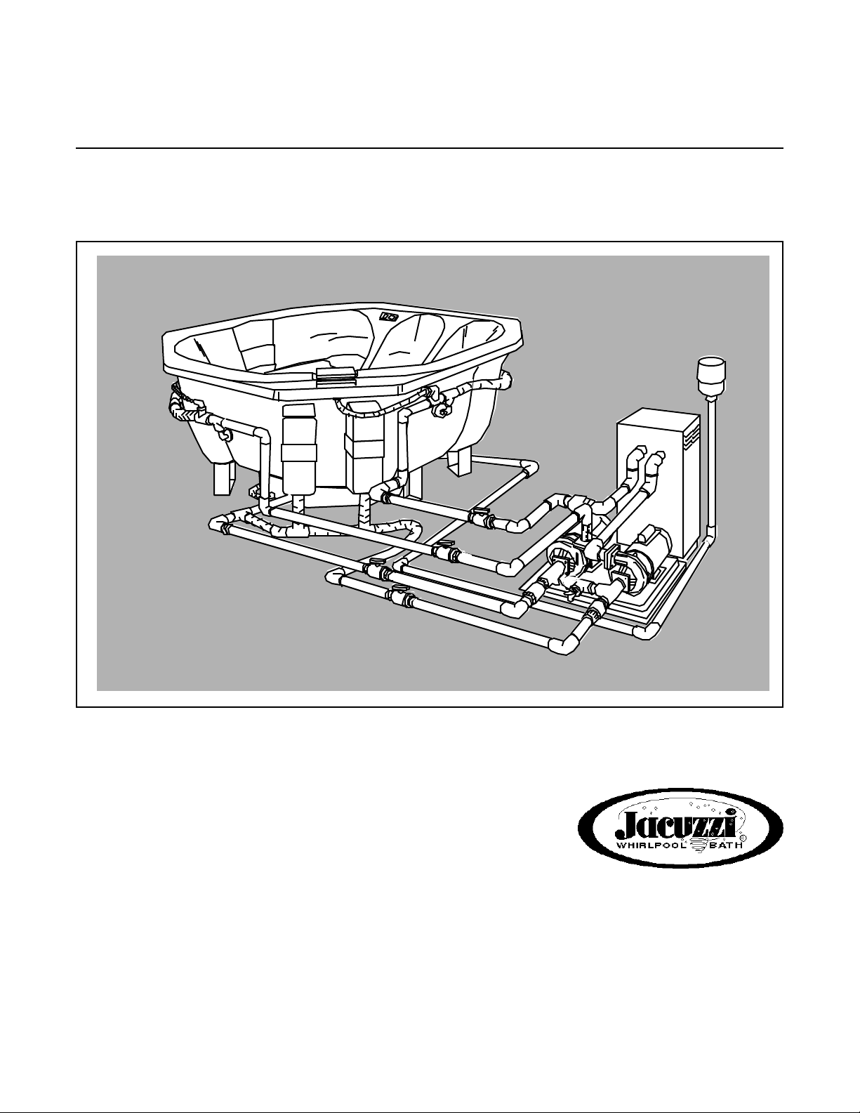
The Cirrus
IG
Owner's Manual
Page 2

IMPORTANT SAFETY INFORMATION
READ AND FOLLOW ALL INSTALLATION INSTRUCTIONS
Jacuzzi Whirlpool Bath does not recommend spa water
temperatures in excess of 104°F. High water temperatures
in excess of 104°F and/or prolonged periods of use can
raise the internal human body temperature excessively and
impair the body’s ability to regulate its internal temperature.
Limit your initial use of the spa to 10-15 minutes. High body
temperatures affect people differently; consult your physician about your safety and comfort before using the spa.
The elderly, the infirm, and children should not use the spa
unattended. Infants should not be permitted in the spa at
water temperatures over 100°F. Pregnant women and
people with heart conditions should consult their physicians
before using the spa at water temperatures over 100°F.
Extra care should be taken when using the spa and consuming alcoholic beverages. Alcohol, drugs, or certain medications such as tranquilizers affect a person’s ability to withstand high temperatures and may produce dangerous effects.
Keep body, hair, and clothing a minimum of 12 inches away
from suction fitting and skimmers at all times when the spa
is operating. Hair longer than shoulder length should be
secured close to the head, or a bathing cap should be worn.
Do not remove the suction grilles! They are safety devices
and must always be in place on the suction fitting to minimize
the potential hazard of hair entanglement or body entrapment.
While the optional spa cover is rigid, it is not designed to
support any weight. Therefore, as a safety precaution, do
not sit, stand or lie on it.
The spa must be installed with adequate electricalservice
access and water drainage system. (See Installation
Instructions.)
When using the electrical equipment, basic safety
precautions should always be followed:
Do not use electrically connected devices such as television, radio, or stereo speakers, lights, cooking devices, or
telephones within 5 feet of the spa while the spa is being
used. Lighting fixtures must not be located directly above
or within 5 feet of the spa. If located within 10 feet of the
spa, they must be on a circuit protected by a GFCI.
Do not apply power to the spa unless it is filled with water
to the normal water level, which is to the water level
indicator mark on the skimmer frame. Activating the spa
when there is an insufficient amount of water can damage
the circulation pump and may cause a fire.
Read manufacturer’s safety information provided with all
optional equipment.
The wet surface of the spa is slippery. Use care when
entering and exiting.
Save These Instructions for Future Use.
Owner's Record
Date Purchased
Purchased From
Installed By
Spa Serial Number Model # D500000
(See page 2 for location of serial number.)
Page 3

The Cirrus IG™ Whirlpool Spa
Owner's Manual
Model D500000
Contents
Page
Installation Instructions
Inspection and Shipping Claim
Unpacking
Indoor Installation,
Outdoor installation, Below Ground
Outdoor installation, Below Ground (cont).
Outdoor Istallation, Ground level or Above
Equipment Pack Site Preparation
Electrical Service
Plumbing
Heater and Air Channel Plumbing
Optional Air Blower
Seat Air Holes
Spa Set-up, Alternative use for Water Rainbow™
Operation Instructions
Equipment Set-up
Priming Procedure I
Priming Procedure II
Spa Controls, Normal Operation
Spa
Silent Air Induction
Water Rainbow™Spout
Maintenance
Water Quality and Water Chemistry
Filtration
Water Chemistry
Disinfecting
Balancing pH
Balancing Total Alkalinity
Water Quality Definitions
Water Level/Drain
Skimmer Basket Maintenance
Filter Maintenance
Automatic Filtration/Maintenance
Winterizing
Cleaning Your Spa
Covering Your Spa
Repairs to the Acrylic
3-14
3
3
4
5
6
7
8
9
10
11
12
13
14
15-19
15
16
17
18
19
19
19
20-24
20
20
20,21
21
21
21
21
22
22
22
23
23
24
24
24
Troubleshooting Guide
25-26
1
Page 4

The Cirrus IG Whirlpool Spa
Specifications
STANDARD FEATURES
• Three directionally-adjustable jets
• Six high volume fully-adjustable jets
• Water Rainbow Fill Spout
recirculating spout
• Two patented front load skimmer/filters
• Safety suction design
• Integrated steps
• Continuous contoured seating
• Separate equipment pack with:
2.0 hp whirlpool motor-pump and
0.75 hp heater/filter motor-pump
EQUIPMENT PACK
SUCTION EQUALIZER TUBE ASSEMBLY
(TO BE INSTALLED ON SITE)
WHIRLPOOL
MOTOR/PUMP
OPTIONS
• Air Blower
• Gas Heater
• Electric Heater
• Rigid Insulated
Spa Cover
• Air Switch/Timer
• Spa Pillows
HEATER/FILTER
MOTOR/PUMP
84"
15"
TYP.
15"
TYP.
84"
AIR CHANNEL HOLES TO
BE DRILLED ON SITE. (OPTIONAL)
84"
32"
SPECIFICATIONS
WHIRLPOOL
MODEL
Cirrus IG
(C500000)
Equipment
Pack
* Shipping weight includes equipment pack weight.
DIMENSIONS
84" (2134 mm) L.
84" (2134 mm)W.
36" (914 mm) H.
32" (81 mm) L.
20" (51 mm) W.
31" (79 mm) H.
MOTOR/PUMP
_
2.0 HP
230 VAC
10.0 AMPS
3450 RPM
Single Phase
60 Hz
32"
HEATER/FILTER
MOTOR/PUMP
_
0.75 HP
230 VAC
4.9 AMP
3450 RPM
Single Phase
60 Hz
PRODUCT SPECIFICATIONS ARE SUBJECT TO CHANGE WITHOUT NOTICE.
3"
36"
SERIAL NUMBER LOCATION
BLACK RECTANGLES IN ILLUSTRATION SHOW PLACEMENT OF WOOD SUPPORTS. SEE PAGE 4 OF
INSTALLATION INSTRUCTIONS.
LOCATE WOODEN SUPPORTS BENEATH OUTER
PERIMETER OF SEATING AREA.
PRODUCT
WEIGHT
321 lbs.
(145.6 kg.)
_
OPERATING
GALLONAGE
375 U.S. gal.
(1419 ltrs.)
_
SHIPPING
WEIGHT
615 lbs.*
(280kg)
_
ELECTRICAL
REQUIREMENTS
_
Two
230 VAC/15 AMP
Circuits
Page 5

INSTALLATION
Inspection and Shipping Claims
Check for shipping damage upon receipt of the spa. Jacuzzi Whirlpool Bath is not responsible for damage to the spa sustained
during shipping. If damage is evident before unpacking, see instructions regarding shipping claims on the outside of the carton and
immediately file a claim with the carrier.
Once the spa has been removed from the carton and before it is permanently installed (see below on this page for unpacking
instructions), check the spa completely for damage. Fill the shell with water and operate the system (see Operating Instructions) to
check for leaks which have resulted from shipping or handling. All Jacuzzi Whirlpool Bath spas are factory tested for proper operation
and water tight connections prior to shipping. If leaks or other problems are detected, immediately notify your Jacuzzi Whirlpool Bath
dealer or Authorized Service Agent, or call Jacuzzi Whirlpool Bath, (510) 938-7070 or (510) 938-7411 for Warranty Service.
Note: Damage or defects which could have been discovered and repaired prior to installation and which are claimed
after final installation of the spa, are excluded from our warranty.
Unpacking
1. Remove the outer carton by disassembling bracing and
side panels.
2. Remove the equipment pack from the pallet by removing
bolts and nuts securing the equipment pack base to the
pallet.
3. The spa should be moved to its final location on a dolly
in its upright position while still attached to its shipping
pallet.
4. When the spa has been moved to its final location,
preferably a concrete pad or other supported surfaces,
place a 4 x 4 x72" wooden block beside the base side
(bottom end) of the spa so it is parallel with the pallet.
5. Tip the spa over onto its bottom with the block supporting
the spa. Do not handle the spa by its plumbing;
handle it by the shell only.
6. Detach the spa from the shipping pallet by removing the
bolts from the pallet.
7. Leave the remaining plastic sheet attached to the spa
shell to keep the shell clean and free from debris during
installation.
8. Before installation begins, remove and retain the owner's
packet from the product accessory box. This packet
contains the Specifications and Installation Instructions,
and Operating Instructions. The accessory box also
contains filters cartridges, skimmer baskets, check valves,
and the equalizer tube assembly with installation hardware and connections to be installed on the equipment
pack. Set aside the filter cartridges in a dry place until it
is time to set up the spa equipment. Read all instructions
contained in both manuals before beginning installation.
9. Record the spa and equipment pack serial number on
the inside front cover of the Owner's manual. (See
illustration on page 2 for the serial number location.)
10. When unpacking optional equipment, keep enclosed
literature for owner's reference.
4 X 4 X 72"
BLOCK
FIBERBOARD
PALLET
REMOVE
BOLTS
BOLTS
4 X 4 BLOCK
3
Page 6

INSTALLATION
DRAIN HOSE HOOK-UP PERMAMENT DRAIN ASSEMBLY
Indoor Installation
Support
If you install your spa indoors, be sure to provide proper
support. The spa is very heavy when filled with water and
in use. The floor or deck it is placed on must be capable of
supporting a 4345 lbs. load, which includes weight of the
spa occupants, water and product. Consult an architect or
engineer to determine the adequacy of your floor or deck to
support this amount of weight. The Spa seating area and
foot well must be fully supported. Construct four 12 3/4" X
34" supports from 2 X 6 redwood or equivalent decayresistant or treated wood. The dimensions given are
approximate; supports should be cut to fit tightly between
the seat area and the floor. Locate the supports as shown
in the illustration on the inside front cover. Do not fill the
spa with water until the supports are installed.
Draining the Spa and Equipment Pack
Two methods of draining a spa installed indoors are
possible. You can install a permanent drain line in the
suction line of the spa, extending from the spa to the house
sewer line and using drain assembly fittings available at
most hardware or plumbing supply stores. Another method
is to install a drain valve in the suction line for hooking up a
garden hose which can be run to the house sewer line or to
an outside storm drain. Check local plumbing codes. See
Illustration below.
If you locate your equipment pack indoors, provide
drainage for that as well. You can attach a garden hose on
the hose bibb provided (once it is installed on the equalizer
tube between suction lines at the pumps) and run it to the
house sewer line when draining the equipment pack
2" X 6" MATERIAL
H
W
2" X 6" MATERIAL ~ REDWOOD OR WOOD
TREATED TO RESIST DETERIORIZATION
QTY SIZE
2 @ 11.0" H X 12.0" W *
1 @ 9.25" H X 12.0" W *
1 @ 9.50" H X 12.0" W *
1 @ 6.25" H X 6.0" W *
1 @ 6.50" H X 6.0" W *
* MATERIALS NOT PROVIDED
Surroundings
Water which splashes on the floor during use may cause
a walking hazard and/or structural damage unless good
drainage is provided and proper building materials are used
in the area surrounding and beneath the spa. Take into
consideration, also, the high room humidity which will exist
due to high spa water temperature. Providing natural or
forced ventilation of the room will help maintain comfort and
minimize moisture damage to the building. Jacuzzi Whirlpool
Bath is not responsible for damageresulting from excess
moisture or water spillage. Consult an architect or engineer
for aid in designing your indoor installation.
TEE*
WHIRLPOOL SUCTION
FROM SPA
HOSE BIB*
2-1/2" TO 3/4"
THREADED ADAPTER*
TEE*
WOODEN SUPPORTS
*PARTS SHOWN ARE NOT PROVIDED
REDUCER*
WHIRLPOOL SUCTION
FROM SPA
1" PVC VALVE*
1" PVC PIPE*
TO DRAIN
SYSTEM
Page 7

INSTALLATION
Outdoor Installation-Below Ground
The overall length of plumping between the spa and the equipment pack must be less than 20 ft. If you are installing your
spa below ground level, the base of the equipment pack must not be more than 9" above the spa rim.
Your spa should be installed so that the air intake opening on the air control assembly is not obstructed by backfill or
insulating material. If, however, your installation will cause the air intake to be restricted because of such obstruction, we
recommend that you construct a protective baffle around the intake to provide a fresh air passage to it.
Backfill Method
If your ground water level is low and drainage is good, you may use the backfill method to install your spa.
Dig a pit 6" deeper than the planned height of your spa and 6" around the outside walls. Since backfilling is below grade,
you should also trench out a plumbing run to the equipment pack at this time. Fill the bottom of the pit and level it. Make
sure the spa is at the desired height. All plumbing connections should be made at this time.
The plumbing system should be tested before completing backfill. (See "Plumbing.") Backfill beneath seat area and
perimeter, wetting the sand occasionally. Important: Use care when backfilling, both to avoid system damage and to prevent
sand from entering the air line system. The backfill should fully support the underside of the seat area and sides. Finishing
material around the spa, such as decking or patio, should not extend beneath the spa rim in such a way that the spa rim, after
shifting or settling of backfill sand, would become the main support of the spa. The spa rim is not designed to support the
weight of the spa. If the rim does support the spa, irreparable damage might occur which is not covered by the warranty.
Note: Do not use the backfill method if ground water level is high or drainage is poor, as hydrostatic pressure may lift the
spa out of the ground. If, because of heavy rains, the ground water level is temporarily high, ensure that the spa is filled
with water (except when cleaning) to compensate for the lifting force.
BACKFILL METHOD
BACKFILL WITH WETTED AND
COMPACTED SAND FOR SUPPORT
SPA RIM
6" MIN. DEPTH
Do not cover piping that is to be enclosed until having
completed a 24-hour leak test. Verify that the spa and
system, once filled with water and primed, are watertight for a 24 hour period before covering piping.
EQUIPMENT PACK BASE
(LOCATE LESS THAN 9"
ABOVE SPA RIM)
2" SHUT-OFF VALVES*
(LOCATE BELOW SPA
WATER LEVEL)
2" PVC PIPING*
*NOT PROVIDED
5
Page 8

INSTALLATION
Outdoor Installation — Below Ground (Continued)
Support Method
If your ground water is high and/or is poor, you will need to build a concrete pad at the bottom of the pit to support
your spa and prevent movement and slippage.
Build forms for a 60" X 72" X 4 " thick level concrete pad. Install a #10 gauge wire 6" X 6" steel reinforced grid. Then
pour concrete. Build wooden supports and fit them under the spa seating area as instructed in "indoor Installation." Refer
to "Support Method" illustration.
Draining the Spa
The spa can be drained to the level of the suction fittings if connected to a drain line or a gravel drain field. Whether the spa
is installed on a concrete pad or in a backfilled pit, install an accessible drain valve in the suction line and run a drain pipe
to a dry well, gravel drain field or storm drain. (See illustrations of suggested drain valve fittings on page 4.) If your spa is
installed lower than any drain field or storm drain, then it will be necessary to drain the spa by hand or by means of an electric
pump. When using an electric pump, observe caution and use a grounded cord, preferably with a plug-in GFCI (Ground Fault
Circuit Interrupter) available at your local hardware or electrical supply store. For maximum safety, do not use an electric
pump while the spa is occupied.
Air Blower Option
In the event that the air blower option may be added by the owner at a later date, we recommend that piping be
stubbed out from the air channel at this time. (See Optional Air Blower section.)
SUPPORT METHOD
BUILD 60" x 72" X 4"
CONCRETE PAD
DRAIN FIELD
SPA RIM
WOODEN
SUPPORTS*
2" SHUT-OFF VALVES*
(LOCATE BELOW SPA
WATER LEVEL)
ALTERNATE
DRAIN LINE
EQUIPMENT PACK BASE
(LOCATE LESS THAN 9"
ABOVE SPA RIM)
2" PVC PIPING
20 FT. MAX PLUMBING LINE
LENGTH BETWEEN SPA AND
EQUIPMENT PACK (INCLUDING
VERTICAL AND HORIZONTAL)
*
*
* NOT PROVIDED
Do not cover piping that is to be enclosed until
having completed a 24-hour leak test. Verify that the
spa and system, once filled with water and primed,
are watertight for a 24 hour period before covering
piping.
6
Page 9

INSTALLATION
CONCRETE PAD*
ABOVE GROUND LEVEL
WOODEN SUPPORTS*
*NOT PROVIDED
GROUND LEVEL
CONCRETE PAD*
2" SHUT-OFF VALVES*
(LOCATED BELOW
SPA WATER LEVEL)
20 FT. MAX. PLUMBING LINE LENGTH BETWEEN SPA AND EQUIPMENT PACK (INCLUDING VERTICAL AND
HORIZONTAL.)
*NOT PROVIDED
WOODEN SUPPORTS*
5' MAX.
VERTICAL
HEIGHT
SEE "SUPPORT METHOD" REQUIREMENTS ABOVE
SEE PAGE 5 (BOTTOM PAGE, BOLD TEXT)
20 FT. MAX. PLUMBING LINE LENGTH BETWEEN SPA AND EQUIPMENT PACK (INCLUDING VERTICAL AND
HORIZONTAL.)
Outdoor Installation — Ground Level or Above
You may install your spa and equipment pack so the spa is at ground level or above. The unique characteristic of the
equipment pack, which allows your spa system to be located away from the spa itself, is that it is designed to allow flexibility
in installation. This means that you can locate your spa on a level higher than the equipment pack, as long as the total
combined horizontal and vertical length of the plumbing lines between the equipment pack and the spa is no more than 20
feet, and as long as the equipment pack base is less than 5 feet below the spa rim.
Support Method
Particularly in deck installations, make sure the floor supporting the spa is strong enough to bear the load of the spa,
which is approximately 4345 lbs. which includes weight of spa occupants, water and product. Consult an architect or engineer
to determine the adequacy of your floor or deck to support this amount of weight. Build wooden seat supports as instructed
in "Indoor Installation".
Draining the Spa
As in other installations, you can install a permanent drain valve in the suction line; this will allow the spa to drain into
a sanitary drain, storm drain, or drain field, (See illustrations of suggested drain valve fittings on page 4.) Consult local codes.
Page 10

INSTALLATION
AIR BLOWER SUPPORT
OPTIONAL
AIR BLOWER*
SUGGESTED AREA
FOR CLASS I
ELECTRICAL
STUBOUT
(REFER TO NEXT
PAGE FOR
ELECTRICAL SERVICE
INFORMATION)
CHECK VALVE
(NOT INCLUDED)
OPTIONAL HEATER
EQUIPMENT PACK BASE
FROM SPA
FROM
SPA
TO
SPA
TO
SPA
FROM
SPA
TO
SPA
LOCATE HEATER WITHIN
5 FT. OF THE EQUIPMENT
PACK TO MINIMIZE
PERFORMANCE LOSS
24"
(36" FOR
GAS HEATER)
36" EQUIPMENT PACK ONLY
48" (FOR ELECTRICAL HEATER)
60" (FOR GAS HEATER)
MOUNT EQUIPMENT PACK
TO CONCRETE PAD
WITH 4 LAG SCREWS
(NOT PROVIDED)
LAG SCREW
(NOT PROVIDED)
EQUIPMENT
PACK BASE
LEAD ANCHOR
(NOT PROVIDED)
Equipment Pack Site Preparation
Locate the equipment pack on a level surface (at least 5 feet but not more than 20 feet from the spa) where there is
sufficient access to the equipment. Make sure the site selected will allow drainage of water away from the equipment pack.
We recommend that you build a concrete pad for the spa equipment. If an electric heater is to be used, the pad should
measure 48" X 24" X 3" thick; if a gas heater is to be used, make the pad 60" X 36" X 3" thick.* The heater must be located
within 5 feet of the equipment pack and on the same level. The pad should be reinforced with 6" X 6" #10 gauge steel wire
mesh grid Attach a #12 solid copper wire to the wire mesh grid with a ground clamp. This wire should be long enough to
reach the bond bar (See "Bonding" in the section on Electrical Service.)
After pouring concrete, and before it has set, locate holes for bolts or anchors to secure the equipment pack based to the
pad. Refer to the hole locations on the flange of the equipment pack base. Then secure the equipment pack base to the
pad. See illustrations on this page for details.
* Refer to heater manufacturer's installation instructions for proper placement and clearance around the heater, as well
as proper plumbing methods. Adjust pressure setting on heater according to manufacturer's instructions, if so equipped.
RECOMMENDED EQUIPMENT LAYOUT
8
Page 11

INSTALLATION
Electrical Service
Since most spa owners are not usually qualified to install the electrical hook-up to the equipment pack, we recommend
that you hire a professional electrician for a completely safe and functional installation. You or your electrician should obtain
whatever electrical permits may be required in your community and have the finished installation inspected by the local
building or electrical inspector. Consult your local building inspection department to determine local requirements. Your
electrician must size the wires to provide adequate amperage and voltage at the equipment pack. The type of wiring
insulation, amperage requirement, and distance from the service panel will determine the wire size (minimum 12 gauge
recommended). See also sections on grounding and bonding.
You will need to purchase a means of controlling your spa equipment pack. We recommend that you install an air switch/
timer such as that available as an option from your Jacuzzi Whirlpool Bath dealer. Follow switch manufacturer's instructions
when installing and refer to addendum sheet included with this product for wiring information. Provide a separate 230 VAC/
15AMP circuit to supply power to each of the motor/pumps. Additional circuits will be needed for any auxiliary equipment,
such as electric heater, air blower or chlorinator.
Note: When installing power wiring to the motors, refer to wiring diagram on motors or behind connection plate.
Bonding
Using a #8 solid copper wire, connect the equipment pack motors, current collector pipes (if an electric heater is used)
and air blower (if used) to a local bonding bar. Also connect all fixed metal objects (metal railings, window frames,
greenhouse structures, lamp poles, fence posts and gutters within 5 feet of the spa to the local bond bar. The local bond
bar must be connected to the house sub-panel or main electrical panel with a #8 solid copper bond wire. Consult your local
building inspection office for requirements. (See National Electrical Code Article 680-22.) Bonding lugs are available at
your local electrical supply store.
Grounding
The continuous service ground (minimum #14 copper) must run inside the electrical supply conduit from the main service
panel to the ground terminal in the equipment. Approved Local Ground. An approved local ground may be an 8 ft. long
ground rod, a ground plate electrode, or a buried metallic water pipe with at least 10 ft. or more of buried pipe. See Article
250 of the NEC or consult your local building code for additional approved grounding methods.
CAUTION
Your equipment pack is an electrical device. It has been made to operate as safely as possible
with many safeguards designed in. It complies with the NEC (National Electrical Code). It must
be installed at least 5 feet away from the spa and grounded properly in order to maintain these
safeguards. (See "Approved Local Ground".) All fixed metals within 5 feet of the spa must be
bonded (see Bonding). Electrical receptacles must be at least 10 feet from inside the rim of the
spa and be of a GFCI (Ground Fault Circuit Interrupter) type, or in a GFCI circuit. Area lighting
must not be located over the spa and must be at least 5 feet horizontally away from the spa rim,
at least 5 feet above the floor or ground. If within 10 feet of spa, it should be in a circuit protected
by a GFCI (see National Electrical Code, Article 680-6).
Without proper grounding and bonding, a system malfunction may cause fatal shock!
9
Page 12

INSTALLATION
Plumbing
Preliminary Assembly
Once your equipment pack is installed, attach the suction
equalizer tube assembly provided to the suction inlets of the
CLEAR PIPE (2)
SUCTION
EQUALIZER
TUBE ASSEMBLY
2" PVC ELL
AIR VENT VALVE (2)
pumps. Align pump flange ends of the assembly and install
using gaskets, bolts and washers provided. Next, install the
1 1/2" x 3/4" reducing bushing and hose bibb provided onto
HOSE BIB
the tee on the equalizer tube. This hose bibb can be used
to drain the equipment pack, and if a garden hose is
attached between it and your water supply, it can help when
priming the pumps. Be sure there is an anti-siphon valve in
the water line to prevent fresh water contamination. Screwon anti-siphon valves are available for easy installation on
the house water spigot.
REDUCER BUSHING
BOLT (8)
PUMP FLANGE
GASKET (2)
PUMP FLANGE (2)
Install the two ells to the clear plastic pipes at the
discharge outlets of the pumps, orienting them in the
direction appropriate for your plumbing layout. Note that
(DOTTED LINES INDICATE PARTS
TO BE INSTALLED ON SITE.)
each ell has a predrilled hole so you can install the two air
vent valves provided. These are necessary to bleed air
from the lines during priming. Install the air vents at this
time.
EQUIPMENT PACK PRELIMINARY ASSEMBLY
Interconnecting Piping
Plumbing lines between the equipment pack and the spa must not be longer than a total of 20 ft., including vertical
and horizontal dimensions.
Use 2" schedule 40 PVC pipe, with as few fittings as possible and bond with PVC solvent cement. When laying out
plumbing lines, avoid making configurations which might cause air entrapment in the system. Four 2" shut-off valves (not
provided) must be installed as close as possible to the equipment pack unit, below the spa water level, and accessible for
normal operation and maintenance. We recommend that they be ball-type valves. Do not use excessive amounts of cement
when bonding the valves to piping. Use pipe primer where required by local codes or when the air temperature during
installation is below 70 degrees F.
Install 2" check valves (swing type) supplied with the spa in the suction line to each pump. These aid in priming and
prevent reverse flow through the heater/filter pump when only the whirlpool pump is running. The arrow on the side of the
check valves must point in the direction of flow. If the base of the equipment pack is to be situated more than 20" higher
than the bottom of the spa shell, locate the check valves in the vertical part of the lines, near the pump.
EQUIPMENT PACK WITH PIPING
SUCTION
SHUT-OFF
VALVES
HOSE BIB
CHECK
VALVES
10
DISCHARGE
AIR VENT VALVE (2)
TO HEATER
PUMP
BOLTS (4)
Page 13

PLUMBING LAYOUT
INSTALLATION
OPTIONAL
AIR BLOWER
OPTIONAL
HEATER
CHECK
VALVE
DISCHARGE
2" PIPING*
(OR LARGER)
20 FT. MAX. PLUMBING LINE LENGTH
BETWEEN SPA AND EQUIPMENT PACK
(INCLUDING VERTICAL AND HORIZONTAL)
SHUT-OFF VALVES*
(LOCATE BELOW
SPA WATER LEVEL)
*SHUT-OFF VALVES AND PLUMBING LINES
NOT PROVIDED BY JACUZZI WHIRLPOOL BATH
SUCTION
CHECK
VALVES
Heater Plumbing
Use at least 4 ft. of copper pipe in the inlet and outlet plumbing of a gas heater (refer to local codes). Install a current
collector in each water line to the heater if an electric heater is used. Piping should be 1 1/2" or larger. You must install a
swing check valve after heater discharge. To minimize performance loss, locate the heater no farther than 5 ft. away from
the equipment pack and at the same elevation. Refer to heater manufacturer's instructions and the "Recommended
Equipment Layout" on page 8.
Air Channel Plumbing
Use 2" PVC schedule 40 pipe for the plumbing line between the optional air blower and the 2" fitting located under the
spa near the skimmer wall. See page 12 for detailed air blower instructions.
Automatic Chlorinators
There are several brands and types of automatic chlorinators available. Automatic chlorinators should be installed
downstream of the heater (all types) with a check valve in the line to ensure that the chlorine solution does not enter the heater
and cause corrosive damage. Your Jacuzzi Whirlpool Bath dealer will be glad to assist you in making your selection.
Note: Use of an automatic chlorinator does not ensure proper water quality. Check and adjust water quality frequently to
prevent corrosive damage, which is not covered by the Jacuzzi Whirlpool Bath warranty.
11
Page 14

2" PVC PIPE
12"
BOTTOM
DISCHARGE
BLOWER
RIGID
SUPPORT FOR
PLUMBING
AIR
CHANNEL
FITTING
INSTALLATION
Optional Air Blower
Two channels under the seating area of your Cirrus IG receive air from the air blower and distribute the air throughholes
in the seating area (to be drilled according to instructions on the following page). As the pressurized air is released from
the holes, tiny bubbles are formed. These bubbles travel upward through the water and expand until they reach the surface,
whereupon they burst. The visual effect of the bursting bubbles contributes to the overall hydromassage experience.
Consult your Jacuzzi Whirlpool Bath dealer for the air blowers available. The minimum rating of the air blower you use
should be 110 cfm, 2.6 psi. For best performance, the blower you select should not exceed this rating by more than 10
percent. See the illustration on page 8 for its recommended location. A bottom discharge blower should be mounted directly
onto a vertical 2" diameter PVC pipe (see illustration on this page). Side discharge blowers that are installed lower than 12"
above the spa's rim must be plumbed with a loop, as illustrated on this page. Some air blower manufacturers recommend
that a check valve also be installed, but use of a check valve instead of a loop is not recommended. Follow blower
manufacturer's instructions when installing.
CAUTION: Wait 24 hours before turning on the air blower, as the PVC cement fumes remaining in the plumbing
are flammable and may explode when the blower is started.
SIDE DISCHARGE BLOWER
LOOP
TYPICAL BOTTOM DISCHARGE
AIR BLOWER ORIENTATION
*LOOP MUST BE AT LEAST
12" ABOVE SPA RIM
12"
12"
2" PVC PIPE
DISCHARGE
BLOWER
SIDE
12
Page 15

INSTALLATION
Seat Air Holes
Because the air blower is an optional feature of the Cirrus IG, air holes are not factory drilled in the seating area. Included
with your spa are an air hole drill guide and a 5/32" diameter drill bit with which to drill the 59 holes required. The drill guide
is shaped to fit the contour of the spa. We recommend that you apply masking tape to the underside of the guide to prevent
scratching the spa surface.
Locate the dimples imprinted in the surface of the seat. (The dimples indicate the center of the air channel located beneath
the seat.) Align the drill guide so that it fits the contour of the spa and is positioned against the footwell wall, and the hole
is over one of the dimples.
Insert the drill bit provided into the drill chuck so that only 1" to 1 1/2" of the drill bit extends out of the chuck. With the
drill guide in place, insert the bit into the guide and proceed to drill with light pressure at low speed through the acrylic,
increasing to high speed to drill through the fiberglass. Continue marking and drilling holes around the seat of the spa until
all holes are drilled at 1 3/4" intervals. (See illustration below.)
Use care when drilling! Failure to use the drill guide or drill bit provided may cause the bit to drill through bottom
of the air channel or cause permanent damage to the shell.
SEAT AIR HOLE DRILLING (WHEN OPTIONAL AIR BLOWER IS INSTALLED)
HAND DRILL
1-1/2" MAX
DIMPLE
DRILL GUIDE
LOCATE AIR HOLE
1-3/4" APART
*Number and size of the holes may vary if a blower other than that recommended on page 12 is used.
13
Page 16

14
Alternate Use of Water Rainbow Spout as Fill Spout
You can use your Water Rainbow spout as a fill spout by permanently plumbing it to a fresh water supply if codes permit.
Local plumbing codes may require the use of an anti-siphon valve for such a connection. Do not interconnect water supply
with recirculating system of the spa.
To make the connections necessary to use the Water Rainbow as a fill spout, follow this procedure:
• Make sure power to the equipment pack is disconnected and spa is drained to below seat level.
• Cut 3/4" flexible piping as shown in illustration below and unscrew connecting fitting at spout.
• Cap off piping by cementing a 3/4" PVC cap where cut has been made.
• Connect permanent plumbing line to the spout.
FRONT ACCESS
SKIMMER/FILTER
Spa Set-Up
Remove the protective plastic rim cover on the
spa. Use care. Stepping into the spa with shoes
will scratch the acrylic surface.
Remove any packing materials from the spa.
Remove each filter cartridge and skimmer basket
from plastic bags.
Pull open each skimmer/filter door by the handle
located in the middle of the door. Insert the filter
cartridge into the filter housing and insert the
skimmer basket so it is in place over the filter
cartridge. Then close the skimmer/filter door.
Clean the interior of the spa of any remaining
construction debris. Remove stubborn stains,
paint or tar with turpentine, isopropyl alcohol or
paint thinner. A mild liquid dishwashing detergent
on a damp cloth is fine for cleaning off other dirt.
Plaster can be removed by scraping with a wooden
edge; do not use a metal scraper, wire brush, or
other metal tools, as they will damage the spa's
surface.
INSTALLATION
SKIMMER BASKET
NYLON ROPE LOOP
WEIR
DOOR
FILETR CARTRRIDGE
WATER RAINBOW SPOUT
INSTALL AND CEMENT3/4" PVC CAP
CUT PIPING HERE (LEAVE 1-1/2" -2")
TEE ON DISCHARGE PIPING
SPA SHELL
3/4" FLEXIBLE PIPING
Page 17

OPERATION
Equipment Set-Up
Important: Your spa equipment pack must have two professionally installed 230 VAC 15 AMP electrical circuits from your
house electrical panel. Additional power will be required for optional equipment, such as heater, air blower, or chlorinator.
A proper ground wire run to a ground approved by your local building or electrical inspector is also required. Make sure the
equipment is properly bonded as instructed in Installation Instructions.
1. Turn OFF all power to the equipment pack by turning off
circuit breakers at the main electrical service panel.
Warning! Turn off all power to the equipment pack
before priming, draining the spa, or performing any
equipment maintenance.
At no time should the whirlpool or filter pump motors
be activated until the pumps are primed and the spa is
filled with water to its normal operating level. Running
the pump dry will cause irreparable damage to the
pump, and the warranty will become void.
EQUIPMENT PACK
CLEAR PIPE (2)
SUCTION
EQUALIZER
TUBE ASSEMBLY
2. Turn on the circuit breakers at the service panel.
3. Follow Priming Procedure, I or II, depending on your
installation type, and check pipes, pumps, and fitting for
leaks.
4. Set thermostat at heater (see heater manufacturer's
operating instructions.)
5. Test for proper water chemistry; then add treatment
chemicals to ensure proper levels. See "Water Quality"
section for details.
2" PVC ELL
AIR VENT VALVE (2)
HOSE BIB
REDUCER BUSHING
PUMP FLANGE
GASKET (2)
BOLT (8)
PUMP FLANGE (2)
(DOTTED LINES INDICATE PARTS
TO BE INSTALLED ON SITE.)
15
Page 18

OPERATION
Priming Procedure I
Use this priming procedure if your installation is such that the base of the equipment pack is level with or above
the rim of the spa (see illustration.)
1. Turn all switches to OFF. Turn OFF circuit breakers at service panel.
2. Open the air vent valves on the plastic elbows.
3. Fill the spa with water with a garden hose to the
spa's normal operating level, which is at the
water level indicator mark on the filter/skimmer
frame.
4. Close the four shut-off valves in the suction and
discharge plumbing.
5. Connect hose to hose bibb on the equalizer tube
between the two pumps. (Make sure anti-siphon
valve is installed at the water source to prevent
contamination of the water supply.)
PRIMING PROCEDURE 1
(ABOVE WATER LEVEL)
6. Open the hose bibb and fill the piping system with
water until water can be seen through clear pipes
on discharge piping.
7. Close the air vent valves when water starts to
flow from them.
8. Close hose bibb and disconnect garden hose.
9. Open four shut-off valves in suction and discharge
piping.
10 Turn ON circuit breakers at the service panel.
11.Turn ON pumps one at a time.
Important: If either pump is not visibly pumping
water at this point, turn off the motor immediately.
Then repeat priming procedures steps.
SPA RIM
SHUT-OFF VALVES AND PIPING NOT PROVIDED BY JACUZZI WHIRLPOOL BATH
BASE
16
EQUIPMENT
PACK
Page 19

OPERATION
Priming Procedure II
Use this priming procedure if your installation is such that the base of the equipment pack is lower than the rim of
the spa (see illustration.)
1. Turn all switches to OFF. Turn OFF circuit breakers at
service panel.
2. Open shut-off valves in the suction and discharge system plumbing.
3. Open the air vents in the plastic elbows.
4. Close the hose bibb located in the equalizer tube between suction lines.
5. Fill the spa with water (using a garden hose) up to its
normal operating level, which is at the water indicator
mark on the skimmer/filter frame. As the water level in
the spa rises, it will bleed air out of the vent valves. When
water flows from the air vents, close them and continue
filling the spa to water indicator mark.
6 .Turn ON the circuit breaker at the service panel.
7. Turn ON the pumps one at a time.
PRIMING PROCEDURE II
(BELOW WATER LEVEL)
SPA RIM
SHUT-OFF VALVES AND PIPING NOT PROVIDED BY JACUZZI WHIRLPOOL BATH
EQUIPMENT
PACK
BASE
17
Page 20

SILENT AIR
CONTROLS
OPERATION
Spa Control
Your Spa and equipment pack installation must include a control system such as an air switch and/or timer system
which will turn the two motor/pumps on and off and provide control of whirlpool, heater and filter functions. Follow
switch manufacturer's instructions for operation.
Warning! At no time should the whirlpool or filter pump motors be activated until the pumps are primed and the spa is
filled with water to its normal operating level. Running the pump dry will cause irreparable damage to the pump,
and the warranty will become void.
All spa heaters have adjustable thermostat settings. The recommended water temperature range for whirlpool bathing
is 90°-98° F. (104° F. max.) . Following the heater manufacturer's instructions, set your heater thermostat to a point which
is comfortable for you within that range. (See Safety Information on the inside front cover.)
Normal Operation
Whirlpool System:
You can enjoy the Cirrus IG spa with or without activating
the whirlpool. Either way, bathing in your spa can be
pleasurable, as well as therapeutic. After a busy, stressful
day, you can look forward to soaking in your spa in still
water with no turbulence—only the gentle warmth of the
soothing and relaxing water.
DIRECTIONALLY ADJUSTABLE
WHIRLPOOL JETS
For a more invigorating spa experience, you can take
advantage of the built-in whirlpool system. To do this,
select the WHIRLPOOL mode at the system control
switch. Sit or recline in the spa so you are comfortable.
Since all the jets are directionally adjustable, you can direct
a jet toward an area where muscles feel tense or stiff. The
warmth of the water and the stimulating water flow from the
jet will pleasantly increase circulation.
For the total whirlpool effect and all-over feeling of well
being, you can adjust all jets so they point in a clockwise or
counterclockwise direction to circulate the air and water
mixture in a circular motion all about the spa.
WATER RAINBOW
SPOUT
SKIMMER/
FILTERS
WATER LEVEL
MARK
SUCTION
COVERS
FULLY ADJUSTABLE
WHIRLPOOL JETS
DIRECTIONALLY
ADJUSTABLE JET
FULLY
ADJUSTABLE
WHIRLPOOL
JET
SILENT
AIR
CONTROL
18
Page 21

OPERATION
™
Water Rainbow
The Water Rainbow spout will add the soothing sound of
a waterfall to your bathing pleasure, as well as provide a
beautiful cascade of shimmering water for an exciting visual
effect.
Activate the waterfall feature by first turning on the
WHIRLPOOL function, then rotate downward the flow control lever located on the left side of the spout. Use this lever
to adjust the amount of water flowing through the Water
Rainbow spout.
CAUTION: The water circulating through the Water
Rainbow spout is not fresh water and therefore is not
suitable for drinking.
Silent Air Induction
The intensity of the whirlpool action is determined by how much air is induced into the water. You have control of this
by adjusting the air induction control knobs (See illustration below). For maximum air induction, rotate each control knob
fully counter clockwise. For fewer air bubbles, decrease the amount of air induction by rotating the control knobs clockwise.
When the knobs are turned fully clockwise, only water is being circulated.
INCREASE AIR FLOW
(COUNTER CLOCKWISE)
DECREASE AIR FLOW
(CLOCKWISE)
CONTROLS
FOR FULLY ADJUSTABLE JETS
INCREASE AIR FLOW
(COUNTER CLOCKWISE)
FOR ADJUSTABLE NECK JETS
DECREASE AIR FLOW
(CLOCKWISE)
CONTROL
19
Page 22

MAINTENANCE
Water Quality and Water Chemistry
Maintaining water quality and water chemistry in your spa is extremely important and should be a regular part of your spa
maintenance program, as a neglected spa can be a breeding place for dangerous bacteria.
The water quality of your spa is maintained by a combination of filtration and chemistry. The spa’s integral filter system
helps maintain the water cleanliness and clarity by trapping most solid materials such as hair and other debris resulting from
normal use. However, the most important part of maintaining water chemistry is keeping the proper level of disinfectant in
the water at all times. This is accomplished by adding chlorine or bromine to the water, which will control particles too small
to be trapped by the filter, such as bacteria and algae, and will oxidize any organic materials. Follow instructions provided
here, and with water quality products, for the health and safety of spa users, as well as to make your spa bathing as enjoyable
as possible.
Filtration
The filtration system of your spa will keep your water
clear and clean if used properly. We recommend that you
run your filter system for at least two hours each day. The
filter cartridge elements will trap most solid materials and
debris in the water. However, the presence of materials
such as body oils or other particles which are too small to
be captured in the filters may bring about various undesirable water quality conditions. These conditions can be
corrected with the use of spa treatment chemicals which
are available from your Jacuzzi Whirlpool Bath dealer.
Such conditions include the following:
Foaming: A de-foamer is available to minimize foaming of
the water. This condition is usually caused by the addition
of soaps or oils, or other fatty substances to the spa water.
The interaction of these with hot water, especially at high
pH (more alkaline) levels, will cause the water to foam.
(See Water Quality Definitions.)
Oil Film or Cloudy Water: Add clarifier to congeal oil film
on the water surface into globules sufficiently large to be
trapped by the system’s filter. Cloudiness is caused by
particles that are too small to be trapped in the filter and is
also due to the presence of human body oils, lotions, and
cosmetics. During normal use, these materials can accumulate on the filter element and clog its pores. The addition
of clarifier will make the water clearer, but may clog filters
which must be cleaned as prescribed under the section
entitled “Filter Maintenance” in this manual.
Water Chemistry
You can ensure better water chemistry by testing your
spa water every day and adjusting the chemical balance
frequently. Obtain a water quality test kit, designed
especially for spas, from your Jacuzzi Whirlpool bath
dealer. The test kit must be of the type which allows you
to test for the disinfectant (chlorine) level, pH, and total
alkalinity. Make sure, also, that the chemicals used in your
spa are especially for spa use, and not for swimming pool,
as water quality maintenance of spas and swimming pools
is very different.
Set up a daily program at first to check the disinfectant
level, pH, and total alkalinity of the water to familiarize your
self with the amount of chemicals to add and to determine
how often to make chemical adjustments during normal
use. Remember that the more heavily the spa is used, the
more often you should check the water chemistry.
When adding any chemicals, always run the filter
system to ensure complete dilution with the water. DO
NOT ADD CHEMICALS DIRECTLY IN THE SKIMMER
OPENING.
Hard Water: Add a de-mineralizer to break down or de-
ionize mineral particles present in the spa water.
Follow the “Filter Maintenance” procedure described in
this manual to ensure optimum performance of your spa’s
filtration system.
20
Page 23

MAINTENANCE
Water Chemistry (continued)
Disinfecting:
Add a disinfectant to the water on a regular basis to help
control the amount of bacteria, algae and organic materials.
Such bacterial contaminants, if not controlled, could cause
skin rashes or other physical problems. To disinfect the spa
for normal use, first establish the amount of chlorine or
bromine to add and determine how often you need to add
it.
We recommend that you maintain a free chlorine level of
2.0-5.0 ppm at all times except when you must exceed that
during the initial purge/sanitizing procedure or during superchlorination (see “Water Quality Definitions” below).
Superchlorinate your spa every two weeks with heavy use.
If using sodium dichlor, add one heaping tablespoon for
each 150 gallons of spa water. Scrub the spa surfaces with
this solution to remove any oily deposits. This will ensure
that any bacteria or algae which are resistant to the normal
disinfectant level are killed. After adding the disinfectant,
run the filter system and allow the free chlorine level to
return to the 2.0 to 5.0 ppm range before using the spa
again. Do not install a rigid cover until the disinfectant
level is back to normal. High concentrations of chlorine
or bromine will damage metallic plated finishes if the
cover is in place.
Balancing pH:
For good hygiene and equipment longevity, maintain the
pH of your spa water according to the instructions provided.
pH is the measure to determine if the spa water is too acid
(low pH) or too alkaline or basic (high pH). The ideal range
for spa water is 7.2 to 7.6 pH. For excessive acidity (below
7.2 pH) add soda ash or sodium bicarbonate to the spa
water. For excessive alkalinity above 7.6 pH add dry acid to
the spa water. Caution: Refer to the spa chemical
manufacturer’s instructions for the initial amount of chemicals to add for the gallonage of your spa. Low pH can cause
equipment damage, as acidic water will dissolve metals,
while high pH can cause scale or calcium deposits to build
up in the system or on the shell. After adding chemicals, run
the filter system for at least 30 minutes before testing water
quality again for accurate readings.
Balancing Total Alkalinity:
Total alkalinity is the measure of base materials in the
water. The recommended range for total alkalinity is between 80 ppm and 150 ppm. If the chemistry of the water
is not within this range, you will have difficulty adjusting the
pH level, which will affect your adjustments for the proper
amount of free available chlorine. If the alkalinity of your spa
water is high, it is advisable to drain the water from the spa,
refill and begin the balancing process over again. Purge
and sanitize your spa (according to instructions in "Equipment Set-Up" section of the "Installation Instructions") and
clean the spa surfaces thoroughly before refilling with fresh
water. Then re-establish water chemistry. If the spa is used
heavily, change the water at least every month.
WATER QUALITY DEFINITIONS
pH: A chemical term used in expressing relative acidity or
alkalinity in numeric values, with 7.0 usually regarded as
neutral, and for purposes of this manual, indicating pure
water. From 7 to 0 indicates increasing acidity, and 7 to 14
indicates increasing alkalinity.
PPM: Parts per million.
Free chlorine: Chlorine that has not combined with other
chemicals and that is available to destroy bacteria in the spa
water.
Trichlor: A form of chlorine used in pool or spa water
treatment; usually supplied in tablet form. Not recommended
because of its higher acidic nature and slow dissolving action.
Prolonged contact with the spa shell may bleach or permanently mark the shell.
Sodium dichlor: The type of chlorine that is recommended
for spa use, as it is available in fast dissolving granular form.
It is neither excessively acid nor alkaline in character and does
not readily dissipate in higher water temperatures.
Calcium hypochlorite: A granular chlorine product that is
inexpensive and effective but not recommended because
it often tends to form calcium deposits on heater parts and
plumbing fittings and leaves an unattractive film on the spa at
the water line.
Sodium hypochlorite: A liquid chlorine product that is
inexpensive and effective but not recommended because the
liquid is readily spilled onto the spa or a surrounding area,
causing permanent damage. It has limited effectiveness at
high water temperatures and readily affects pH balance.
Total alkalinity: The measure of the amount of alkaline
materials (such as carbonates, bicarbonates and hydroxides) in the water. High alkalinity inhibits the effectiveness of
chemicals to change the pH. If the alkalinity of your spa water
is high (above 150 ppm), it is advisable to drain the water from
the spa and begin the balancing process over again. Low
total alkalinity (below 60 ppm) could be corrosive and damage your spa system.
Superchlorination: (Also referred to as “shock treatment”.)
The addition of an above-normal level of disinfectant to kill
any bacteria or algae that might have become resistant to
normal levels of disinfectant.
21
Page 24

22
Replacement cartridges are available through your
Jacuzzi Whirlpool Bath Dealer.
The suction covers located in the foot well area should be
checked at least once a week for collected debris, such as
leaves, hair, etc., and cleaned as necessary. It may not be
necessary to remove the suction cover to clean it, but if you
need to, remove the center screw with a Phillips type
screwdriver and clean the cover by flushing with water from
a hose.
CAUTION: Be sure to replace the suction cover imme-
diately after cleaning. It is a safety device and must be
in place over the suction fitting to minimize potential
hazard of hair and body entrapment.
If heavy rains raise the spa water level, drain the spa to
its normal level.
The optional rigid spa cover , when in place over the spa,
will help reduce evaporation and control the amount of
debris entering the spa when the spa is not occupied. In
addition, its use will reduce energy consumption.
NORMAL WATER LEVEL
Skimmer Basket Maintenance
The basket located in the skimmer of the spa should be
checked at least once a week for collection of debris, such
as leaves, hair, etc., and cleaned as necessary. To clean
the basket, remove it from the skimmer by pulling it out; then
backflush it with a garden hose and reinstall.
MAINTENANCE
Water Level/Drain
The water level in the spa must be maintained at its
normal level. Evaporation and splashing will cause the
water level to drop.
When concentrations of impurities from evaporation,
water quality chemicals, body oils, perfumes, dirty feet, and
winds, etc., accumulate in the spa and cannot be filtered
out, it is necessary to drain your spa and refill it with fresh
water. This should be done every 2 months or more often
depending on the amount of use.
After draining the spa, clean the spa shell, suction
covers, skimmer, and filter, then close the drain valve and
refill the spa with fresh water. Check the pH level and
maintain water quality.
FRONT ACCESS
SKIMMER/FILTER
SKIMMER BASKET
NYLON ROPE LOOP
WEIR
DOOR
NORMAL WATER
LEVEL MARKER
FILETR CARTRRIDGE
Filter Maintenance
The filters should be checked periodically. In normal
use, check the filters at least once a month. Keep the filters
clean; obstructed filters reduce water quality and inhibit
proper system performance.
A removable filter cartridge is located inside each skimmer. To remove it, pull open the skimmer door by the handle
located in the middle of the door. Slide the basket out, then
pull the filter cartridge upward and out of the housing by the
loop at the top of the filter. Clean the filter by separating the
folds of the filter and spraying with fresh water from a garden
hose. Then reinstall the cartridge in the housing and
replace the basket, reversing the above procedure.
Oils will coat the filter, resulting in a reduced flow. To
remove such materials, soak the cartridge in a plastic pail
containing a commercial filter cleaning solution (available
from your Jacuzzi Whirlpool Bath dealer or most pool
supply stores). Follow the manufacturer’s instructions for
use. Another method is to soak the filter cartridge in a
plastic pail containing a mild solution of trisodium phosphate (TSP) and water. An hour of soaking time is usually
required to break down oil coatings from the cartridge. Use
a stronger solution of TSP and water to remove algae. Most
hardware or paint stores stock TSP. Use the same method
of cleaning when the cartridge becomes plugged with clay
or vegetation.
Page 25

MAINTENANCE
Automatic Filtration/Maintenance
The spa should be covered to keep out debris. The filter cycle should be run at least two hour per day to maintain water quality.
If your equipment pack has a timer installed, the timer may turn on the filter automatically each day for you in your absence.
Your timer may also function to turn on the heater to maintain a certain water temperature. (Refer to optional switch/timer
instructions.)
During prolonged periods of no use, the evaporation of water from the spa will cause the water level to fall below the
skimmer level.* Long periods (two weeks or more) without water quality maintenance are not recommended. If spa water
care cannot be maintained, turn off the main service panel switch (or sub-panel switch), drain and cover the spa.
Another means of maintaining minimum water quality while you are away for less than two weeks is to follow the procedure
outlined for winterizing your spa in a warm climate. (See Winterizing.) Note: We do not recommend using this procedure
if you are absent during the summer, when algae build-up is most likely.
Always keep your spa covered when not in use to reduce heat loss and evaporation and to prevent debris from falling in.
*Warning: If motor/ pump(s) is activated when the spa water is low, when the spa has been drained, or when the
pump has lost its prime, the pump could become irreparably damaged.
Winterizing
In a climate where winter temperatures are below
freezing, follow this procedure when the spa will NOT
be used:
Note: If the spa is to be used during winter in a cold
climate, see warm climate instructions below.
1. Turn off the power to the equipment pack.
2. Drain the spa and equipment.
Note: If your spa is installed below ground and the
ground water level in your area is high or drainage is
poor, do not drain the spa (except for cleaning), as
hydrostatic pressure may lift the spa out of the ground.
Follow warm climate instructions for winterizing.
3. Remove the filter cartridges, clean them, and store
them dry.
4. Remove the lower 1/4" plugs from the face of each
pump housing, drain the pumps, then replace the plugs.
5. Obtain pure glycerine (Glycerol) from a druggist or other
source. Mix 2 parts of glycerine to 1 part water and pour
approximately one cup into each pump at the upper
drain plug opening. A syringe or other similar device
may speed up this process. Re-insert upper drain plug.
Do not use automotive anti-freeze.
In a warm climate where there are occasional freezing
temperatures, follow this procedure:
1. Set the thermostat on the heater to its minimum
temperature which, typically, is between 45°-65° F.
2. Run filter cycle daily during freezing conditions.
4. Maintain a chemical balance. (See Water Quality section.)
4. Use optional rigid spa cover for increased energy efficiency. This procedure allows usage of the spa during
winter months with a minimum energy requirement.
CAUTION: Not winterizing will cause irreversible
damage (at freezing temperatures) to the pump and
or plumbing lines.
After the spa has drained keep water and debris out by
covering with a water-proof cover.
Before using the spa again, see filling instructions in
appropriate Priming Procedure.
PLUG
PLUG
23
Page 26

MAINTENANCE
Cleaning Your Spa
Your Cirrus IG spa shell consists of two layers of plastic
materials. Its smooth top surface of acrylic is tough and
durable and contains concentrated color. This is supported
by a substantial thickness of fiberglass-reinforced polyester resin. A catalyst causes a chemical reaction during
manufacturing that bonds these layers permanently into a
hard, strong material. With a minimum amount of care and
cleaning, your whirlpool spa will look new for years.
To clean your spa, simply use a mild, non-abrasive liquid
detergent, isopropyl alcohol, or commercially prepared spa
cleaner. Do not use abrasive cleaners. You can protect
and restore the gloss to a dulled surface by applying
Meguiar’s #10 Mirror Glaze, which is a product specifically
designed for use on acrylic finishes. If Meguiar’s is not
available, an acrylic polish of equal quality or automotive
paste wax will do.
Use a spa cleaner for residue buildup at the water level
of the spa surface. This may be applied to the acrylic
surface with a soft cloth and wiped clean. Use sparingly in
small amounts to avoid contaminating the spa water. If the
spa is heavily soiled, it may be advisable to lower the water
level 2 - 3 inches before cleaning, then refill to normal level.
Covering Your Spa
An optional rigid spa cover is available to place on top of
the spa. The use of this cover will help to reduce energy
costs by minimizing heat loss and evaporation from your
spa. In addition, the attractive spa cover is an effective
means of preventing debris such as leaves and dirt from
entering your spa when not in use. Follow the instructions
for use and care provided with the spa cover.
CAUTION: While the spa cover is rigid it is not designed to support any weight. Therefore, as a safety
precaution and to preserve the life of your cover, you
must not sit, stand, or lie on it; nor should you place
objects of any kind on top of it.
Jacuzzi Whirlpool Bath does not guarantee or warranty
this cover. Refer to spa cover manufacturer's information provided with the cover.
Repairs to the Acrylic
Minor scratches which do not penetrate the color finish
(acrylic) can be removed with 600-grit wet/dry sandpaper.
Restore the glossy finish with Meguiar's #10 Mirror Glaze or
comparable automotive paste wax.
Major scratches or gouges which penetrate the acrylic
surface will require refinishing. Ask your Jacuzzi Whirlpool
Bath Dealer for special instructions.
24
Page 27

TROUBLESHOOTING GUIDE
PROBLEM REMEDYPROBABLE CAUSE
1. Water will not heat.
2. Water not clean.
3. Abnormal water usage.
4. Low water flow
from jets.
A. No power to the heater.
B. Thermostat set too low.
C. Pressure switch set too high
on gas heater.
D. Failure of heater thermostat.
E. Filter pump not on.
A. Filters clogged (dirty).
B. Skimmer basket clogged.
C. Clogged or blocked suction
strainer.
D. Improper maintenance.
E. High content of solids in
water.
A. Excess evaporation..
B. Leak in plumping line.
A. Only filter pump running.
B. Only whirlpool pump running.
C. Dirty filter(s).
D. Plugged strainers.
E. Low water level.
F. Shut-off valves closed.
G. Suction, skimmer, or
discharge partially clogged.
H. Worn or damaged pump seal.
I. Foreign object lodged in pump.
A. Check circuit breaker.
B. Reset thermostat.
C. Adjust pressure switch.
D. *
E. Check circuit breaker.
A. Clean or replace.
B. Clean.
C. Clean.
D. See Maintenance/Water
Chemistry.
E. Drain and refill spa.
A. Use spa thermal cover.
B. Repair leak.
A. Turn on whirlpool pump.
B. Turn on filter pump.
C. Clean and replace.
D. Clean.
E. Fill spa to middle of skimmer
opening.
F. Open valves.
G. Clean strainers or skimmer baskets.
H. *
I. *
5. No water flow from jets.
6. Noisy pump and motor.
* Note: The skills and tools necessary for the safe repair of this spa require the services of qualified service
personnel. Contact your Jacuzzi Whirlpool Bath Authorized Service Agent or Dealer.
A. Circuit breaker tripped.
B. Shut-off valve closed.
C. Low water level.
D. Leak in suction line,
discharge line or connections.
E. Pump or motor faulty.
F. Pumps lost prime.
A. Leakage of air into suction.
B. Blocked suction.
C. Vibrating parts attached to
motor or support brackets.
E. Damaged or worn motor
bearings.
F. Impeller rubbing inside case.
G. Debris inside pump.
A. Reset circuit breaker.
B. Open valves.
C. Fill spa to middle of skimmer
opening.
D. Repair leaks.
E. *
F. Prime pumps
A. Locate and repair leaks.
B. Clean suction strainers.
C. Tighten fasteners.
E. *
F. *
G. *
25
Page 28

26
* Note: The skills and tools necessary for the safe repair of this spa require the services of qualified service personnel.
Contact your Jacuzzi Whirlpool Bath Authorized Service Agent or Dealer.
TROUBLESHOOTING GUIDE
REMEDYPROBABLE CAUSEPROBLEM
7. Water leakage at pump
shaft. (rotating connection
between pump and motor).
8. Motor will not start.
9. Motor stops.
A. Worn or damaged pump seal.
B. Foreign matter trapped
in pump.
A. Optional timer or switch
set at OFF.
B. Circuit breaker tripped or in
OFF position.
C. Locked shaft or impeller.
D. Disconnected or defective
wiring.
E. Defective starting switch inside
motor.
F. Motor winding burned out.
G. Auxiliary switch malfunction.
A. Optional timer or switch set
at OFF.
B. Circuit breaker tripped or in
off position.
C. Switch failure.
D. Motor overload condition.
E. Auxiliary switch malfunction.
A. *
B. *
A. Turn to ON.
B. Reset circuit breaker.
C. *
D. *
E. *
F. *
G. *
A. Turn to ON.
B. Turn to ON.
C. *
D. Let cool for one hour. Motor
overload will reset, then start
again. If problem persists,
contact your Jacuzzi Whirlpool
Bath dealer for service.
E. *
10. Will not hold prime.
A. Air leak through faulty or
open vent valves.
B. Water or air leak in system
plumbing.
C. Low water level.
D. Faulty check valves.
A. Close or repair vent valve.
B. Repair leak.
C. Fill spa to middle of skimmer
opening.
D. Replace valves.
Page 29

a
Printed on Recycled Paper
Jacuzzi Whirlpool Bath has obtained applicable code (standards) listings generally available on a national basis for products of this type.
It is the responsibility of the installer/owner to determine specific local code compliance prior to installation of this product. Jacuzzi Whirlpool
Bath makes no representation or warranty regarding, and will not be responsible for any code compliance.
PRODUCT SPECIFICATIONS ARE SUBJECT TO CHANGE WITHOUT NOTICE.
USE INSTALLATION INSTRUCTIONS SUPPLIED WITH PRODUCT.
Jacuzzi Whirlpool Bath National Headquarters
P.O. Drawer J, Walnut Creek, CA 94596 (510) 938-7070
Service Support: Call (800) 288-4002
©1993 Jacuzzi Whirlpool Bath D492000 9/93
Printed in the U.S.A.
 Loading...