

Jacuzzi AMIGA, ALARIS, ALENA 6, CASELLE, BIANCA Installation & Operating Instructions Manual
...Page 1

BUILDER BATH SERIES
INSTALLATION/OPERATING INSTRUCTIONS
SERIE DE TINAS BUILDER
MANUAL DE INSTALACIÓN Y OPERACIÓN
R
WHIRLPOOL
BATH
Page 2

SUMMARY OF PRECAUTIONS
• Suction cover must be in place at all times to minimize the potential for hair and body entrapment.
• Keep body and hair a minimum of 6" away from suction fitting at all times when the whirlpool system is operating. Hair longer than shoulder
length should be secured close to the head.
• Never operate electrical appliances (hairdryer, telephone, television, radio etc.) inside or within 5 feet of the bath.
• Never leave small children unattended in the bath.
• Do not operate the whirlpool system unless the bath is filled with water to at least 2" above the highest jet.
• Do not use oil-based bath additives in your whirlpool bath.
• When cleaning your bath, do not use abrasive substances which will damage the bath's surface.
•A maximum water temperature of 104°F is recommended. Bathing at temperatures above 104°F for prolonged periods can be injurious to
health.
• To prevent discoloration of the acrylic finish, do not fill the bath with water in excess of 140°F.
IMPORTANT SAFETY INSTRUCTIONS
WARNING: When using this unit, basic precautions should always be followed, including the following:
Read and follow all instructions.
DANGER: to reduce the risk of injury, do not permit children to use this unit unless they are closely supervised at all times.
Use this unit only for its intended purpose as described in this manual. Do not use attachments not recommended by the manufacturer.
Never drop or insert any object into any opening.
Do not operate this unit without the suction cover in place.
This unit must be connected only to a supply circuit that is protected by a ground fault circuit interrupter (GFCI). Such a GFCI should be provided
by the installer and should be tested on a routine basis. To test the GFCI, push the test button. The GFCI should interrupt power. Push the reset
button. Power should be restored. If the GFCI fails to operate in this manner, there is a ground current flowing, indicating a possibility of an
electric shock. Do not use this unit. Disconnect the unit and have the problem corrected by a qualified service representative before using.
A pressure wire connector is provided on the exterior of the motor to permit connection of an No. 8 A WG (8.4 mm) solid copper bonding conductor
between this unit and all other electric equipment and exposed metal in the vicinity, as needed to comply with local requirements.
WARNING: When using electrical products, basic precautions should always be followed including the following:
DANGER: RISK OF ELECTRIC SHOCK. Connect only to a circuit protected by a ground fault circuit interrupter.
Grounding is required. This unit should be installed by a qualified service representative and grounded.
(For built-in and custom units.) Install to permit access for servicing.
NORMAS DE SEGURIDAD
• La placa protectora de succión debe estar siempre en su lugar para reducir al mínimo el riesgo de que el cabello o alguna parte del cuerpo
queden atrapados.
• Mantenga el cuerpo y el cabello a una distancia mínima de 6” con respecto al mecanismo de succión cuando esté funcionando el sistema.
El cabello largo hasta los hombros debe llevarse recogido.
• No encienda aparatos eléctricos (secador de pelo, teléfono, televisión, radio, etc.) en la tina o en un radio de 5 pies.
• No deje a los niños solos en la tina.
• No active el sistema hidroterapéutico a menos que el nivel del agua llegue 2” arriba del chorro más alto.
• No use aceites para baño en la tina de hidromasaje.
• Para limpiar la tina no use sustancias abrasivas que puedan dañar la superficie.
• Una maximua temperatura de 104°F es recomendable. Bañares a temperaturas mas altas de 104∞F por periodeos prolongados puede ser
perjudicial a su salud.
• Para evitar la decoloración del terminado acrílico, cuide que la temperatura del agua no pase de 140°F (60°C).
NORMAS DE SEGURIDAD IMPORTANTES
PRECAUCIÓN: Al utilizar esta unidad deben observarse normas de seguridad básicas, incluidas las siguientes:
Lea y siga todas las instrucciones.
PELIGRO: Para reducir el riesgo de lesiones no permita que los niños usen la unidad a menos que los supervise todo el tiempo un adulto.
Dé a la unidad el uso previsto y siga las instrucciones descritas en este manual. Sólo utilice los accesorios recomendados por el fabricante.
No deje caer ni inserte objetos en los orificios.
No opere la unidad si la placa protectora de succión no está en su lugar.
La unidad sólo debe conectarse a un circuito de alimentación protegido por un interruptor de circuito para fallas puesto a tierra (ICFT), que debe
proveer el instalador. Revise el ICFT en forma rutinaria; para hacerlo, oprima el botón de prueba y se interrumpirá la energía eléctrica. Oprima
el botón de reposición para restaurar la energía. Si aun siguiendo estas instrucciones el ICFT no funciona correctamente, fluye una corriente a
tierra que indica la posibilidad de que haya una descarga eléctrica. No utilice la unidad en esas condiciones. Desconecte la unidad y cerciórese
de que un representante autorizado corrija la falla antes de usarla.
En la parte externa del motor se encuentra un conector de cables a presión que permite la conexión de un conductor de cobre No. 8AWG
(8.4mm) entre la unidad y el equipo eléctrico y metales expuestos cercanos, a fin de cumplir con las normas de instalación aplicables.
PRECAUCIÓN: Al utilizar esta unidad deben observarse normas de seguridad básicas, incluidas las siguientes:
PELIGRO: RIESGO DE DESCARGA ELÉCTRICA. Conecte la unidad sólo a un circuito protegido con un interruptor de circuito para fallas
puesto a tierra. Es necesario hacer la conexión a tierra. Se recomienda que un representante de servicio autorizado instale y conecte la unidad
a tierra.
Page 3

CONTENTS
TABLA DE CONTENIDO
Specifications _________________________________________________________________________ 2-7
Especificaciones
Roughing-in Reference _________________________________________________________________ 8-12
Diagramas de instalaciones
Framing and Support ___________________________________________________________________ 10-11
Estructura y soporte
Service Access _______________________________________________________________________ 13
Registros
Electrical Connections___________________________________________________________________ 15
Conexiones eléctricas
Plumbing and Water Supply ______________________________________________________________ 16
Plomería y suministro de agua
Operation ____________________________________________________________________________ 17-20
Funcionamiento
Rapid Heat Operation & Electrical Connections ______________________________________________ 20-21
Rapid Heat funcionamiento y conexiones eléctricas
Warranty _____________________________________________________________________________ 23-26
Save These Instructions for Future Use.
Conserve Estas Instrucciones Para Uso Futuro.
Owner's Record
Registro del Propietario
Date Purchased ____________________________________________________________
Fecha de compra
Purchased From ____________________________________________________________
Comprado a
Installed By ________________________________________________________________
Instalado por
Serial Number _____________________________________________________________
Número de serie
Model ____________________________________________________________________
Número de modelo
1
Page 4

Important: Read complete instructions before beginning installation.
Each whirlpool bath arrives ready for installation, completely equipped with motor/pump assembly and plumbing and fittings necessary for
whirlpool operation. An optional drain/overflow kit is available for installation on the bath.
Remove the bath from the carton. Retain the shipping carton until satisfactory inspection of the product has been made. Do not lift the bath
by the plumbing at any time; handle by the shell only.
Immediately upon receipt, inspect the shell before installing. Should inspection reveal any damage or defect in the finish, do not install the
bath. Damage or defect to the finish claimed after the bath is installed is excluded from the warranty. Jacuzzi Whirlpool Bath's responsibility for
shipping damage ceases upon delivery of the products in good order to the carrier. Refer any claims for damage to the carrier . For definitions of
warranty coverage and limitations, refer to the published warranty information packed with the product.
All bath units are factory tested for proper operation and watertight connections prior to shipping. Note: Prior to installation, the bath must
be filled with water and operated to check for leaks that may have resulted from shipping damage or mishandling. Jacuzzi Whirlpool
Bath is not responsible for any defect that could have been discovered, repaired, or avoided by following this inspection and testing procedure.
Importante: Lea las instrucciones antes de iniciar la instalación.
Las tinas de hidromasaje se entregan listas para instalarse y completamente equipadas con motor, bomba, accesorios de plomería y mecanismos
necesarios para el hidromasaje. La instalación del equipo de desagüe y rebosadero es opcionál.
Saque la tina de su caja; consérvela hasta haber revisado completamente el producto. No levante la tina sujetándola por los accesorios
de plomería, sino por el casco.
Inspeccione el casco de la tina en cuanto la reciba. En caso de que detecte algún daño o desperfecto en el terminado, no la instale. La
garantía no cubre daños o desperfectos reclamados después de la instalación. La responsabilidad de Jacuzzi Whirlpool Bath por daños de
embarque termina al entregar los productos en buen estado al distribuidor. Presente sus reclamaciones por daños al distribuidor. Para mayor
información sobre la cobertura de la garantía, consulte la garantía publicada en el empaque del producto.
El funcionamiento de las tinas y el buen estado de las conexiones han sido probados en fábrica antes del embarque. Nota: Antes de la
instalación, llene la tina con agua y enciéndala para verificar que no presente fugas provocadas durante el embarque o por mal
manejo. Jacuzzi Whirlpool Bath no se hace responsable por desperfectos que pudieran haberse descubierto, reparado o evitado de haberse
seguido este procedimiento de inspección y verificación.
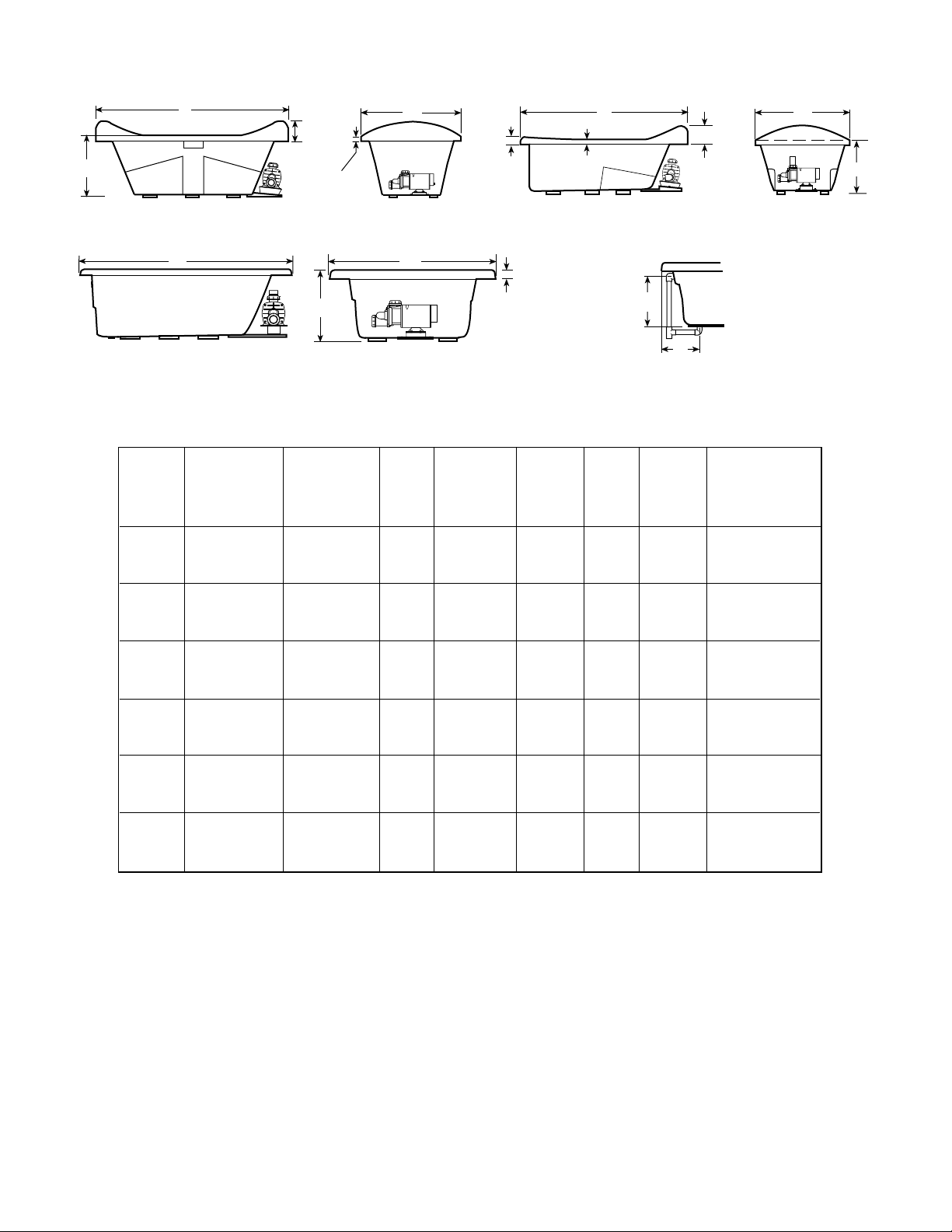
L
2"
51 mm
H
W
L
1"
25.4 mm
H
W
SIDE VIEW
SIDE VIEW
VISTA LATERAL
END VIEW
VISTA DE FRENTE
VISTA LATERAL
BATHS WITHOUT INTEGRAL SKIRT
TINAS SIN FALDÓN INTEGRADO
L
SIDE VIEW
VISTA LATERAL
1"
25.4 mm
H
VISTA DE FRENTE
W
END VIEW
SIDE VIEW
VISTA LATERAL
BATHS WITH 3-SIDED TILE FLANGE
TINAS CON PESTAÑA DE 3 LADOS
A
B
DRAIN/OVERFLOW
DESAGÜE/REBOSADERO
SPECIFICATIONS (Rectangular) ESPECIFICACIONES (Rectangular)
DRAIN/OVERFLOW
MODEL
MODELO
ALENA™ 5
ALENA™ 5
WITH INTEGRAL
SKIRT
CON FALDÓN
INTEGRADO
DIMENSIONS
MEDIDAS
60" (1524 mm) L
36" ( 914 mm) W
19-1/4" ( 489 mm) H
60" (1524 mm) L
36" ( 914 mm) W
19-1/4" ( 489 mm) H
DIMENSIONS
MEDIDAS DEL
DESAGÜE/
REBOSADERO
15-1/8" (384 mm) A
9" (229 mm) B
14-5/8" (372 mm) A
9" (229 mm) B
CUTOUT
CORTE
58" x 34"
NA
TOTAL WEIGHT/
FLOOR LOADING
CARGA TOTAL
SOBRE EL PISO
633 lb
(287 kg)/
42 lb/sq. ft.
(205 kg/sq.) m
648 lb
(294 kg)/
43 lb/sq. ft.
(210 kg/sq. m)
OPERATING
GALLONAGE
CAPACIDAD
35/48 U.S. gal
(133/182 litros)
35/48 U.S. gal
(133/182 litros)
END VIEW
VISTA DE FRENTE
BATHS WITH INTEGRAL SKIRT
TINAS CON FALDÓN INTEGRADO
L
1"
25.4 mm
H
VISTA DE FRENTE
BATHS WITH 4-SIDED TILE FLANGE
TINAS CON PESTAÑA DE 4 LADOS
AVAILABILITY OF
"RAPIDHEAT"
IN LINE HEATER
DISPONIBILIDAD DE
TRANSFERENCIA DE
CALOR
Yes
Sí
No
PRODUCT
WEIGHT
PESO
83 lb
(38 kg)
98 lb
(45 kg)
SKIRT &
MOUNTING
FALDÓN Y
MONTAJE
Not
Available
No
Disponible
Integral
Integrado
W
END VIEW
2
Page 5

SPECIFICATIONS (Rectangular) ESPECIFICACIONES (Rectangular)
DRAIN/OVERFLOW
MODEL
MODELO
ALENA™ 6
WITH INTEGRAL
SKIRT
CON FALDÓN
INTEGRADO
ALARIS™
DIMENSIONS
MEDIDAS
72" (1829 mm) L
36" ( 914 mm) W
19" ( 483 mm) H
72" (1829 mm) L
42" (1067 mm) W
22" ( 559mm) H
DIMENSIONS
MEDIDAS DEL
DESAGÜE/
REBOSADERO
14-5/8" (372 mm) A
9-3/8" (238 mm) B
18-3/4" (476 mm) A
13-5/16" (216 mm) B
CUTOUT
CORTE
Page 10
Pagina 10
NA
See
Vea
TOTAL WEIGHT/
FLOOR LOADING
CARGA TOTAL
SOBRE EL PISO
755 lb
(342 kg)/
43 lb/sq. ft.
(210 kg/sq. m)
1036 lb
(471 kg)/
49 lb/sq. ft.
(239 kg/sq. m)
OPERATING
GALLONAGE
CAPACIDAD
50/62 U.S. gal
(189/235 litros)
67 U.S. gal
(254 litros)
PRODUCT
WEIGHT
PESO
108 lb
(49 kg)
110 lb
(50 kg)
SKIRT &
MOUNTING
FALDÓN Y
MONTAJE
Integral
Integrado
Not
Available
No
Disponible
AVAILABILITY OF
"RAPIDHEAT"
IN LINE HEATER
DISPONIBILIDAD DE
TRANSFERENCIA
DE CALOR
Yes
Sí
Yes
Sí
AMIGA™ 72" (1829 mm) L
BIANCA™ 72" (1829 mm) L
CASELLE™
WITH INTEGRAL
SKIRT
CON FALDÓN
INTEGRADO
CETRA™
WITH INTEGRAL
SKIRT
CON FALDÓN
INTEGRADO
CIVA™ 60" (1524 mm) L
EURA™ 72" (1829 mm) L
LUNA™ 60" (1524 mm) L
LUXURA™ 5 60" (1524 mm) L
LUXURA™ 5
WITH INTEGRAL
SKIRT
CON FALDÓN
INTEGRADO
LUXURA™ 5.5
MADIRA™
36" ( 914 mm) W
20-3/4" ( 527 mm) H
48" (1219 mm) W
20-1/2" ( 521 mm) H
60" (1524 mm) L
30" ( 762 mm) W
20-1/4" ( 483 mm) H
60" (1524 mm) L
32" ( 813 mm) W
20-1/2" ( 521 mm) H
36" ( 914 mm) W
21-1/4" ( 540 mm) H
42" (1067 mm) W
20" ( 508 mm) H
32" ( 813 mm) W
19" ( 483 mm) H
32" ( 813 mm) W
20-1/4" ( 514 mm) H
60" (1524 mm) L
32" ( 813 mm) W
20-1/4" ( 514 mm) H
66" (1676 mm) L
34" ( 864 mm) W
20" ( 508 mm) H
60" (1524 mm) L
42" (1067 mm) W
20-1/4" ( 508 mm) H
16-7/8" (429 mm) A
14" (356 mm) B
16" (406 mm) A
8-1/2" (216 mm) B
16-3/4" (425 mm) A
9-1/4" (235 mm) B
17-7/8" (454 mm) A
9-3/8" (238 mm) B
16-3/4" (426 mm) A
9-3/8" (238 mm) B
16-3/8" (416 mm) A
10-1/4" (260 mm) B
15-3/4" (400 mm) A
9-1/4" (235 mm) B
16-1/4" (387 mm) A
9-1/4" (210 mm) B
15-1/4" (387 mm) A
8-1/4" (210 mm) B
15-1/4" (387 mm) A
8-3/8" (213 mm) B
16-3/4" (425 mm) A
8-7/8" (225 mm) B
70" x 34"
70" x 46"
NA
NA
58" x 34"
70" x 40"
58" x 30"
NA
Molded-in
Tile Flange
Pestaña
Moldeada
de Azulejo
NA
64" x 32"
See
Page 10
Vea
Pagina 10
797 lb
(362 kg)/
45 lb/sq. ft.
(220 kg/sq. m)
1143 lb
(519 kg)/
48 lb/sq. ft.
(234 kg/sq. m)
719 lb
(326 kg)/
54 lb/sq. ft.
(263 kg/sq. m)
719 lb
(326 kg)/
54 lb/sq. ft.
(263 kg/sq. m)
700 lb
(318 kg)/
47 lb/sq. ft.
(229 kg/sq. m)
915 lb
(415 kg)/
44 lb/sq. ft.
(215 kg/sq. m)
604 lb
(275 kg)/
45 lb/sq. ft.
(220 kg/sq. m)
659 lb
(300 kg)/
50 lb/sq. ft.
244 kg/sq. m
659 lb
(300 kg)/
50 lb/sq. ft.
244 kg/sq. m
697 lb
(316 kg)/
40 lb/sq. ft.
(195 kg/sq. m)
789 lb
(358 kg)/
45 lb/sq. ft.
(220 kg/sq. m)
49 U.S. gal
(186 litros)
73 U.S. gal
(276 litros)
49 U.S. gal
(186 litros)
35/57 U.S. gal
(132/216 litros)
44 U.S. gal
(167 litros)
72 U.S. gal
(273 litros)
41 U.S. gal
(155 litros)
44 U.S. gal
(167 litros)
44 U.S. gal
(167 litros)
51 U.S. gal
(193 litros)
45 U.S. gal
(170 litros)
105 lb
(48 kg)
135 lb
(61kg)
94 lb
(43 kg)
94 lb
(43 kg)
92 lb
(42 kg)
140 lb
(64 kg)
79 lb
(36 kg)
92 lb
(42 kg)
92 lb
(42 kg)
110 lb
(50 kg)
97 lb
(44 kg)
Optional,
U-Frame
Opcional,
marco en “U”
Optional,
U-Frame
Opcional,
marco en “U”
Integral
Integrado
Integral
Integrado
Optional,
U-Frame
Opcional,
marco en “U”
Optional
Opcional
Optional,
U-Frame
Opcional,
marco en “U”
Optional,
U-Frame
Opcional,
marco en “U”
Optional,
U-Frame
Opcional,
marco en “U”
Optional,
U-Frame
Opcional,
marco en “U”
Not
Available
No
Disponible
Yes
Yes
Yes
Yes
Sí
No
Yes
Sí
Yes
Sí
Yes
Yes
No
No
Sí
Sí
Sí
Sí
Sí
MAGNA™
MAJORA™ 5
60" (1524 mm) L
48" (1219 mm) W
22" ( 559 mm) H
60" (1524 mm) L
42" (1067 mm) W
19-1/2" ( 495 mm) H
17-1/2" (445 mm) A
13-1/8" (333 mm) B
15" (381 mm) A
8-3/4" (222 mm) B
FOR ALL UNITS:
MOTOR/PUMP: 115 VAC, 3450 RPM/10 AMP, 60 Hz Single phase.
ELECTRICAL REQUIREMENTS: 115 VAC, 15 AMP, 60 Hz. Requires
dedicated separate circuit.
58" x 46"
58" x 40"
1209 lb
(548 kg)/
61 lb/sq. ft.
(298 kg/sq. m)
678 lb
(308 kg)/
39 lb/sq. ft.
(190 kg/sq. m)
3
49 U.S. gal
(186 litros)
40/52 U.S. gal
(151/197 litros)
118 lb
(54 kg)
95 lb
(43 kg)
Optional,
U-Frame
Opcional,
marco en “U”
Not
Available
No
Disponible
Yes
Sí
Yes
Sí
PARA TODAS LAS UNIDADES:
Motor/bomba: 115 VCA, 3450 RPM/10 AMP, 60 Hz, Monofásico.
Requisitos eléctricos: 115 VCA, 15 AMP, 60 Hz. Requiere un
circuito dedicado independiente.
Page 6

SPECIFICATIONS (Rectangular) ESPECIFICACIONES (Rectangular)
DRAIN/OVERFLOW
DIMENSIONS
MODEL
MODELO
MAJORA™ 6
MAJORA™ 6
WITH INTEGRAL
SKIRT
CON FALDÓN
INTEGRADO
MITO™ 5
MITO™ 6
NAVONA™ 60" (1524 mm) L
NAVONA™
WITH
INTEGRAL
SKIRT
CON
FALDÓN
INTEGRADO
NOVA™ 5
NOVA™ 5
WITH INTEGRAL
3-SIDED TILE
FLANGE
CON PESTAÑA
DE 3 LADOS
INTEGRADA
NOVA™ 5
WITH INTEGRAL
4-SIDED TILE
FLANGE
CON PESTAÑA
DE 4 LADOS
INTEGRADA
NOVA™ 5
WITH INTEGRAL
SKIRT
CON FALDÓN
INTEGRADO
NOVA™ 6 72" (1829 mm) L
SIGNA™ 60" (1524 mm) L
SIGNA™ 60" (1524 mm) L
DIMENSIONS
MEDIDAS
72" (1829 mm) L
42" (1067 mm) W
19-3/4" ( 502 mm) H
72" (1829 mm) L
42" (1067 mm) W
19-3/4" ( 502 mm) H
60" (1524 mm) L
42" (1067 mm) W
21" ( 533 mm) H
72" (1829 mm) L
42" (1067 mm) W
21-1/2" ( 546 mm) H
36" ( 914 mm) W
21-1/4" ( 553 mm) H
60" (1524 mm) L
36" ( 914 mm) W
21-1/4" ( 553 mm) H
60" (1524 mm) L
42" (1067 mm) W
18-1/4" ( 457 mm) H
60" (1524 mm) L
42" (1067 mm) W
18-1/2" ( 470 mm) H
60" (1524 mm) L
42" (1067 mm) W
18-1/2" ( 470 mm) H
60" (1524 mm) L
42" (1067 mm) W
18-1/2" ( 470 mm) H
42" (1067 mm) W
20-1/2" ( 521 mm) H
42" (1067 mm) W
22" ( 559 mm) H
42" (1067 mm) W
22" ( 559 mm) H
MEDIDAS DEL
DESAGÜE/
REBOSADERO
15-5/8" (397 mm) A
10-1/2" (267 mm) B
15-5/8" (397 mm) A
10-1/2" (267 mm) B
17-1/2" (445 mm) A
11-7/8" (302 mm) B
17-1/2" (445 mm) A
11-7/8" (302 mm) B
18-1/2" ( 470 mm) A
9" ( 229 mm) B
18-1/2" ( 470 mm) A
9" ( 229 mm) B
14-3/4" (375 mm) A
8-1/2" (216 mm) B
14-3/4" (375 mm) A
8-1/2" (216 mm) B
14-3/4" (375 mm) A
8-1/2" (216 mm) B
15-3/4" (400 mm) A
8-1/4" (210 mm) B
14-3/4" (375 mm) A
8-1/2" (216 mm) B
17-1/2" (445 mm) A
12-1/2" (318 mm) B
17-1/2" (445 mm) A
12-1/2" (318 mm) B
FOR ALL UNITS:
MOTOR/PUMP: 115 VAC, 3450 RPM/10 AMP, 60 Hz Single phase.
ELECTRICAL REQUIREMENTS: 115 VAC, 15 AMP, 60 Hz. Requires
dedicated separate circuit.
CUTOUT
70" x 40"
58" x 40"
70" x 40"
Template
Provided
Plantilla
Poveida
58" X 34"
58" x 40"
70" x 40"
58" x 40"
58" x 40"
CORTE
NA
NA
NA
NA
TOTAL WEIGHT/
FLOOR LOADING
CARGA TOTAL
SOBRE EL PISO
930 lb
(422 kg)/
44 lb/sq. ft.
(215 kg/sq. m)
940 lb
(426 kg)/
44 lb/sq. ft.
(215 kg/sq. m)
900 lb
(408 kg)/
51 lb/sq. ft.
(249 kg/sq. m)
1060 lb
(481 kg)/
51 lb/sq. ft.
(249 kg/sq. m)
840 lb
(605 kg)/
56 lb/sq. ft.
304 kg/sq. m
840 lb
(605 kg)/
56 lb/sq. ft.
304 kg/sq. m
789 lb
(358 kg)/
45 lb/sq. ft.
(220 kg/sq. m)
789 lb
(358 kg)/
45 lb/sq. ft.
(220 kg/sq. m)
789 lb
(358 kg)/
45 lb/sq. ft.
(220 kg/sq. m)
695 lb
(315 kg)/
40 lb/sq. ft.
(195 kg/sq. m)
885 lb
(402 kg)/
42 lb/sq. ft.
(205 kg/sq. m)
883 lb
(401 kg)/
51 lb/sq. ft.
(249 kg/sq. m)
883 lb
(401 kg)/
51 lb/sq. ft.
(249 kg/sq. m)
OPERATING
GALLONAGE
CAPACIDAD
60/80 U.S. gal
(227/303 litros)
60/80 U.S. gal
(227/303 litros)
47/78 U.S. gal
(178/295 litros)
57/96 U.S. gal
(216/363 litros)
60/65 U.S. gal
(227-246 liters)
60/65 U.S. gal
(227-246 liters)
45 U.S. gal
(170 litros)
45 U.S. gal
(170 litros)
45 U.S. gal
(170 litros)
45/52 U.S. gal
(170/197 litros)
62 U.S. gal
(235 litros)
42 U.S. gal
(159 litros)
42 U.S. gal
(159 litros)
PARA TODAS LAS UNIDADES:
Motor/bomba: 115 VCA, 3450 RPM/10 AMP, 60 Hz, Monofásico.
Requisitos eléctricos: 115 VCA, 15 AMP, 60 Hz. Requiere un
circuito dedicado independiente.
PRODUCT
WEIGHT
PESO
104 lb
(47 kg)
114 lb
(52 kg)
100 lb
(45 kg)
110 lb
(50 kg)
130 lb
(59 kg)
130 lb
(59 kg)
97 lb
(44 kg)
97 lb
(44 kg)
97 lb
(44 kg)
112 lb
(51 kg)
110 lb
(50 kg)
108 lb
(49 kg)
108 lb
(49 kg)
SKIRT &
MOUNTING
FALDÓN Y
MONTAJE
Not
Available
No
Disponible
Integral
Integrado
Optional,
U-Frame
Opcional,
marco en “U”
Not Available
No
Disponible
Optioal
U Frame
Optioal
U Frame
Optional,
U-Frame
Opcional,
marco en “U”
Not
Available
No
Disponible
Not
Available
No
Disponible
Integral
Integrado
Optional,
U-Frame
Opcional,
marco en “U”
Optional,
U-Frame
Opcional,
marco en “U”
Optional,
U-Frame
Opcional,
marco en “U”
AVAILABILITY OF
"RAPIDHEAT"
IN LINE HEATER
DISPONIBILIDAD DE
TRANSFERENCIA
DE CALOR
Yes
Sí
Yes
Sí
No
No
Yes
Yes
Yes
Sí
Yes
Sí
Yes
Sí
No
Yes
Sí
Yes
Sí
Yes
Sí
4
Page 7

SPECIFICATIONS (Rectangular) ESPECIFICACIONES (Rectangular)
DRAIN/OVERFLOW
DIMENSIONS
MODEL
MODELO
SIGNA™
WITH INTEGRAL
3-SIDED TILE
FLANGE
CON PESTAÑA
DE 3 LADOS
INTEGRADA
SIGNA™
WITH INTEGRAL
4-SIDED TILE
FLANGE
CON PESTAÑA
DE 4 LADOS
INTEGRADA
SIGNA™ 6
SIGNA™ 6
WITH INTEGRAL
4-SIDED TILE
FLANGE
CON PESTAÑA
DE 4 LADOS
INTEGRADA
TORINO™
TORINO™ 6 72" (1829 mm) L
VANTAGE™
VANTAGE™
WITH INTEGRAL
SKIRT
CON FALDÓN
INTEGRADO
DIMENSIONS
MEDIDAS
60" (1524 mm) L
42" (1067 mm) W
22" ( 559 mm) H
60" (1524 mm) L
42" (1067 mm) W
22" ( 559 mm) H
72" (1829 mm) L
42" (1067 mm) W
22" ( 559mm) H
72" (1829 mm) L
42" (1067 mm) W
22" ( 559mm) H
66" (1676 mm) L
42" (1067 mm) W
20-1/2" ( 521 mm) H
48" (1219 mm) W
22-1/4" ( 565 mm) H
60" (1524 mm) L
32" ( 813 mm) W
18-1/2" ( 470 mm) H
60" (1524 mm) L
32" ( 813 mm) W
18-1/2" ( 470 mm) H
MEDIDAS DEL
DESAGÜE/
REBOSADERO
17-1/2" (445 mm) A
12-1/2" (318 mm) B
17-1/2" (445 mm) A
12-1/2" (318 mm) B
16-7/8" (429 mm) A
14" (356 mm) B
16-7/8" (429 mm) A
14" (356 mm) B
15" (381 mm) A
13-1/2" (343 mm) B
18-3/8" (467 mm) A
22-1/2" (572 mm) B
14-1/2" (368 mm) A
9-3/8" (238 mm) B
14-1/2" (368 mm) A
9-3/8" (238 mm) B
FOR ALL UNITS:
MOTOR/PUMP: 115 VAC, 3450 RPM/10 AMP, 60 Hz Single phase.
ELECTRICAL REQUIREMENTS: 115 VAC, 15 AMP, 60 Hz. Requires
dedicated separate circuit.
CUTOUT
70" x 40"
64" x 40"
70" x 46"
CORTE
NA
NA
NA
NA
NA
TOTAL WEIGHT/
FLOOR LOADING
CARGA TOTAL
SOBRE EL PISO
883 lb
(401 kg)/
51 lb/sq. ft.
(249 kg/sq. m)
883 lb
(401 kg)/
51 lb/sq. ft.
(249 kg/sq. m)
1168 lb
(530 kg)/
56 lb/sq. ft.
(273 kg/sq. m)
1168 lb
(530 kg)/
56 lb/sq. ft.
(273 kg/sq. m)
800 lb
(363 kg)/
42 lb/sq. ft.
(205 kg/sq. m)
1232 lb
(559 kg)/
51 lb/sq. ft.
249 kg/sq. m
617 lb
(280 kg)/
46 lb/sq. ft.
(224 kg/sq. m)
617 lb
(280 kg)/
46 lb/sq. ft.
(224 kg/sq. m)
OPERATING
GALLONAGE
CAPACIDAD
42 U.S. gal
(159 litros)
42 U.S. gal
(159 litros)
55 U.S. gal
(208 litros)
55 U.S. gal
(208 litros)
54 U.S. gal
(204 litros)
59/114 U.S. gal
(223/431 litros)
38 U.S. gal
(144 litros)
38 U.S. gal
(144 litros)
PARA TODAS LAS UNIDADES:
Motor/bomba: 115 VCA, 3450 RPM/10 AMP, 60 Hz, Monofásico.
Requisitos eléctricos: 115 VCA, 15 AMP, 60 Hz. Requiere un
circuito dedicado independiente.
PRODUCT
WEIGHT
PESO
108 lb
(49 kg)
108 lb
(49 kg)
118 lb
(54 kg)
118 lb
(54 kg)
108 lb
(49 kg)
133 lb
(60 kg)
92 lb
(42 kg)
92 lb
(42 kg)
SKIRT &
MOUNTING
FALDÓN Y
MONTAJE
Optional,
U-Frame
Opcional,
marco en “U”
Optional,
U-Frame
Opcional,
marco en “U”
Not
Available
No
Disponible
Not
Available
No
Disponible
Optional,
U-Frame
Opcional,
marco en “U”
Not
Available
No
Disponible
Included,
U-Frame
Opcional,
marco en “U”
Included,
U-Frame
Opcional,
marco en “U”
AVAILABILITY OF
"RAPIDHEAT"
IN LINE HEATER
DISPONIBILIDAD DE
TRANSFERENCIA
DE CALOR
Yes
Sí
Yes
Sí
Yes
Sí
Yes
Sí
Yes
Sí
Yes
Sí
Yes
Sí
Yes
Sí
5
Page 8
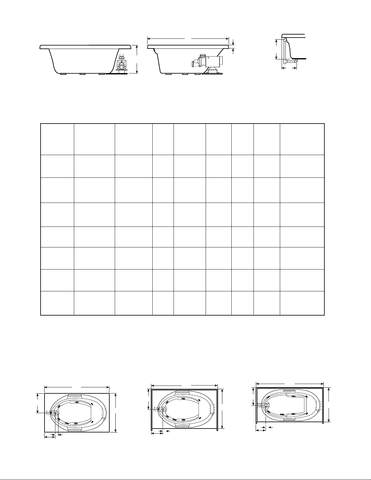
RIMLESS OVAL BATHS
TINAS OVALADAS SIN BORDES
L
7-1/2"
H
SIDE VIEW
VISTA LATERAL
L
191 mm
FRESCO
2"
25.4 mm
END VIEW
VISTA DE FRENTE
W
3-1/2"
89 mm
VISTA LATERAL
L
2'' (25.4 mm)
SIDE VIEW
8"
203 mm
W
H
END VIEW
VISTA DE FRENTE
MILANO
W
2''
25.4 mm
SIDE VIEW
VISTA LATERAL
H
END VIEW
VISTA DE FRENTE
RIVA 5 & RIVA 6
NIVEO 5 & NIVEO 6
SPECIFICATIONS (Oval) ESPECIFICACIONES (Ovaladas)
DRAIN/OVERFLOW
MODEL
MODELO
FRESCO™
MILANO™
NIVEO™ 5 62" (1575 mm) L
NIVEO™ 6
RIVA™ 5
RIVA™ 6
DIMENSIONS
MEDIDAS
71-1/2" (1816 mm) L
42" (1067 mm) W
23-3/4" ( 603 mm) H
71-1/2" (1816 mm) L
40" (1016 mm) W
20-3/4" ( 527 mm) H
43" (1092 mm) W
18-1/2" ( 470 mm) H
72" (1829 mm) L
42" (1067 mm) W
20-1/2" ( 521 mm) H
62" (1575 mm) L
43" (1092 mm) W
18-1/2" ( 470 mm) H
72" (1829 mm) L
42" (1067 mm) W
20-1/2" ( 521 mm) H
DIMENSIONS
MEDIDAS DEL
DESAGÜE/
REBOSADERO
20-1/8" (511 mm) A
11-3/4" (299 mm) B
18-1/2" (470 mm) A
11" (279 mm) B
14-3/4" (375 mm) A
9-1/2" (241 mm) B
16" (406 mm) A
11-1/2" (292 mm) B
14-3/4" (375 mm) A
9-1/2" (241 mm) B
16" (406 mm) A
11-1/2" (292 mm) B
CUTOUT
CORTE
Template
Provided
Poveida
Template
Provided
Template
Provided
Plantilla
Poveida
Template
Provided
Plantilla
Poveida
Template
Provided
Plantilla
Poveida
Template
Provided
Plantilla
Poveida
Plantilla
Plantilla
Poveida
TOTAL WEIGHT/
FLOOR LOADING
CARGA TOTAL
SOBRE EL PISO
1071 lb
(486 kg)/
51 lb/sq. ft.
(249 kg/sq. m)
987 lb
(447 kg)/
50 lb/sq. ft.
(244 kg/sq. m)
788 lb
(357 kg)/
58 lb/sq. ft.
(283 kg/sq. m)
880 lb
(399 kg)/
52 lb/sq. ft.
(254 kg/sq. m)
788 lb
(357 kg)/
58 lb/sq. ft.
(283 kg/sq. m)
880 lb
(399 kg)/
52 lb/sq. ft.
(254 kg/sq. m)
OPERATING
GALLONAGE
CAPACIDAD
63 U.S. gal
(239 litros)
60 U.S. gal
(227 litros)
48 U.S. gal
(182 litros)
75 U.S. gal
(235 litros)
48 U.S. gal
(182 litros)
62 U.S. gal
(235 litros)
A
B
DRAIN/OVERFLOW
DESAGÜE/REBOSADERO
AVAILABILITY OF
"RAPIDHEAT"
IN LINE HEATER
DISPONIBILIDAD DE
TRANSFERENCIA
DE CALOR
PRODUCT
WEIGHT
PESO
130 lb
(59 kg)
135 lb
(61 kg)
96 lb
(44 kg)
105 lb
(48 kg)
96 lb
(44 kg)
105 lb
(48 kg)
SKIRT &
MOUNTING
FALDÓN Y
MONTAJE
Not
Available
No
Disponible
Not
Available
No
Disponible
Not
Available
No
Disponible
Not
Available
No
Disponible
Not
Available
No
Disponible
Not
Available
No
Disponible
Yes
Yes
Yes
Sí
Yes
Yes
Sí
Sí
Sí
Sí
Yes
Sí
FOR ALL UNITS:
MOTOR/PUMP: 115 VAC, 3450 RPM/10 AMP, 60 Hz Single phase.
ELECTRICAL REQUIREMENTS: 115 VAC, 15 AMP, 60 Hz. Requires
dedicated separate circuit.
PARA TODAS LAS UNIDADES:
Motor/bomba: 115 VCA, 3450 RPM/10 AMP, 60 Hz, Monofásico.
Requisitos eléctricos: 115 VCA, 15 AMP, 60 Hz. Requiere un
circuito dedicado independiente.
6
Page 9
CORNER BATHS
TINAS DE ESQUINA
H
SIDE VIEW
VISTA LATERAL
END VIEW
VISTA DE FRENTE
CORNER BATHS
TINAS DE ESQUINA
SPECIFICATIONS (Corner) ESPECIFICACIONES (De Esquina)
MODEL
MODELO
DIMENSIONS
MEDIDAS
DRAIN/OVERFLOW
DIMENSIONS
MEDIDAS DEL
DESAGÜE/
REBOSADERO
CUTOUT
CORTE
TOTAL WEIGHT/
FLOOR LOADING
CARGA TOTAL
SOBRE EL PISO
L
A
2"
51 mm
B
DRAIN/OVERFLOW
DESAGÜE/REBOSADERO
AVAILABILITY OF
"RAPIDHEAT"
IN LINE HEATER
DISPONIBILIDAD DE
TRANSFERENCIA
DE CALOR
OPERATING
GALLONAGE
CAPACIDAD
PRODUCT
WEIGHT
PESO
SKIRT &
MOUNTING
FALDÓN Y
MONTAJE
CAPELLA™ 60" (1524 mm) L
CAPELLA™
WITH INTEGRAL
SKIRT
CON FALDÓN
INTEGRADO
CAPELLA™ 55
WITH INTEGRAL
SKIRT
CON FALDÓN
INTEGRADO
STELANO™
STELLARIA™
TARA™
TARA™
WITH INTEGRAL
SKIRT
CON FALDÓN
INTEGRADO
60" (1524 mm) L
20-1/2" ( 521 mm) H
60" (1524 mm) L
60" (1524 mm) L
20-1/2" ( 521 mm) H
55" (1397 mm) L
55" (1397 mm) L
20-1/2" ( 521 mm) H
60" (1524 mm) L
60" (1524 mm) L
22-1/2" ( 572 mm) H
55" (1397 mm) L
55" (1397 mm) L
20-1/4" ( 514 mm) H
60" (1524 mm) L
60" (1524 mm) L
20-3/4" ( 527 mm) H
60" (1524 mm) L
60" (1524 mm) L
20-3/4" ( 527 mm) H
18" (457 mm) A
12-1/8" (308 mm) B
18" (457 mm) A
12-1/8" (308 mm) B
18" (457 mm) A
12-1/8" (308 mm) B
18-1/8" (451 mm) A
10-7/8" (276 mm) B
17-1/2" (445 mm) A
9-5/8" (245 mm) B
16" (406 mm) A
12-3/8" (314 mm) B
16" (406 mm) A
12-3/8" (314 mm) B
FOR ALL UNITS:
MOTOR/PUMP: 115 VAC, 3450 RPM/10 AMP, 60 Hz Single phase.
ELECTRICAL REQUIREMENTS: 115 VAC, 15 AMP, 60 Hz. Requires
dedicated separate circuit.
See
Page 12
Vea
Pagina 12
NA
NA
See
Page 12
Vea
Pagina 12
See
Page 12
Vea
Pagina 12
See
Page 12
Vea
Pagina 12
NA
1100 lb
(499 kg)/
52 lb/sq. ft.
(254 kg/sq. m)
1110 lb
(505 kg)/
52 lb/sq. ft.
(254 kg/sq. m)
1050 lb
(477 kg)/
52 lb/sq. ft.
(254 kg/sq. m)
993 lb
(451 k/g)/
44 lb/sq. ft.
215 kg/sq. m
808 lb
(367 kg)/
43 lb/sq. ft.
(210 kg/sq. m)
1093 lb
(496 k/g)/
55 lb/sq. ft.
(268 kg/sq. m)
1093 lb
(496 k/g)/
55 lb/sq. ft.
(268 kg/sq. m)
60 U.S. gal
(227 litros)
60 U.S. gal
(227 litros)
55 U.S. gal
(208 litros)
62 U.S. gal
(235 litros)
51 U.S. gal
(193 litros)
74 U.S. gal
(280 litros)
74 U.S. gal
(280 litros)
120 lb
(54 kg)
130 lb
(59 kg)
120 lb
(54 kg)
110 lb
(50 kg)
116 lb
(53 kg)
118 lb
(54 kg)
118 lb
(54 kg)
Not
Available
No
Disponible
Integral
Integrado
Integral
Integrado
Not
Available
No
Disponible
Optional
Opcional
Optional
Opcional
Integral
Integrado
No
No
No
No
Yes
Sí
Yes
Sí
No
PARA TODAS LAS UNIDADES:
Motor/bomba: 115 VCA, 3450 RPM/10 AMP, 60 Hz, Monofásico.
Requisitos eléctricos: 115 VCA, 15 AMP, 60 Hz. Requiere un
circuito dedicado independiente.
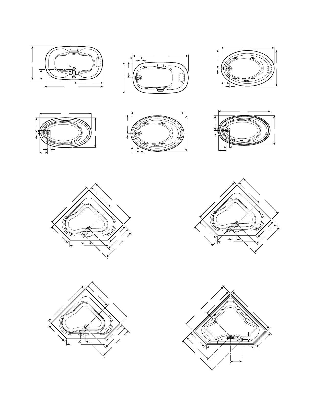
ROUGHING-IN REFERENCE
DIAGRAMAS EN PLANTA DE INSTALACIONES
Note: Unless otherwise specified, units are produced with left or right-hand versions.
Nota: Si no se ha especificado de otra manera, las unidades se ofrecen con la bomba a la izquiera o a la derecha.
*
2"
10" x 4"
7
60"
18"
36"
9-3/8"
ALENA 6 WITH INTEGRAL SKIRT
ALENA 6 CON FALDÓN INTEGRADO
18"
*
60"
18"
10" x 4"
2"
9"
ALENA 5
36"
9"
ALENA 5 WITH INTEGRAL SKIRT
ALENA 5 CON FALDÓN INTEGRADO
2"
*
72
10" x 4"
36"
Page 10

ROUGHING-IN REFERENCE
DIAGRAMAS EN PLANTA DE INSTALACIONES
Note: Unless otherwise specified, units are produced with left or right-hand versions.
Nota: Si no se ha especificado de otra manera, las unidades se ofrecen con la bomba a la izquiera o a la derecha.
*
2"
60
10" x 4"
12" x 4"
2"
CIVA
32"
2-1/2"
*
60"
LUXURA 5 WITH INTEGRAL SKIRT
LUXURA 5 CON FALDÓN INTEGRADO
8-1/4"
16"
8-1/4"
16"
2-1/2"
36''
42"
18''
*
72"
18-1/2" x 5"
13-5/16"
11-
1/4"
5"
36"
ALARIS
*
72''
16'' x 4''
14''
2''
AMIGA
16"
9-3/8"
CETRA WITH INTEGRAL SKIRT
CETRA CON FALDÓN INTEGRADO
18"
36"
8-1/2''
(Left-hand only as shown.)
(Mano izquiersda (como mostrado) solamente)
*
60"
15" x 5"
LUXURA 5
*
60"
15" x 5"
32"
32"
* 72"
24"
13-1/2" x 4"
8-1/2"
13-3/4"
(Left-hand only as shown.)
(Mano izquierda (como mostrado) solamente)
48"
BIANCA
*
60"
9-1/4"
14-3/8"
15" x 5"
2-1/2"
30"
CASELLE WITH INTEGRAL SKIRT
CASELLE CON FALDÓN INTEGRADO
*
72"
4-1/4"
10" x 5"
36"
42"
(Right-hand only as shown.)
(Mano derecha (como mostrado) solamente)
EURA
*60"
16"
14" x 4"
2"
6-1/2"
(Left-hand only as shown.)
LUNA
31-5/8"
5-1/2"
4-7/8"
32"
2''
17"
2-1/2"
21''
8-1/2''
8-3/8"
LUXURA 5.5
11" x 4"
2''
MADIRA
15" x 5"
*
60"
*
66"
34"
42''
8
Page 11

ROUGHING-IN REFERENCE
DIAGRAMAS EN PLANTA DE INSTALACIONES
Note: Unless otherwise specified, units are produced with left or right-hand versions.
Nota: Si no se ha especificado de otra manera, las unidades se ofrecen con la bomba a la izquiera o a la derecha.
*60"
48"
(Right-hand only as shown.)
(Mano derecha (como mostrado) solamente)
16" x 6"
4-1/2"
30"30"
MAGNA
12"
11-7/8"
(Left- and right-hand determined by pump location.)
(Es izquierda o derecha según la ubicación de la bomba.)
30"
*
60"
10" x 4"
2"
MITO 5
42"
21''
2''
8-1/2''
NOVA 5 WITH 3-SIDED TILE FLANGE
NOVA 5 CON PESTAÑA DE 3 LADOS
11" x 4"
2''
*
60"
42''
21"
21"
8-3/4"
10-1/2"
2"
*
60"
2"
10" x 4"
MAJORA 5
*
72"
12" x 4"
MAJORA 6
42"
42"
*72"
10" x 4"
2"
11-7/8"
36"
(Left- and right-hand determined by pump location.)
(Es izquierda o derecha según la ubicación de la bomba.)
MITO 6
*60"
12” x 4”
18"
9"
(Cutout template included in shipping carton.
Iincluyen una plantilla en la caja)
NAVONA/
NAVONA WITH INTEGRAL SKIRT
NAVONA/
NAVONA CON FALDÓN INTEGRADO
36"
42"
*
60"
21''
2''
8-1/2''
11" x 4"
2''
42''
NOVA 5 WITH INTEGRAL SKIRT
NOVA 5 CON FALDÓN INTEGRAL
60"
21''
2''
8-1/2''
11" x 4"
2''
(Left-hand only as shown.)
42''
NOVA 5 WITH 4 SIDED FLANGE
NOVA 5 CON PESTAÑA DE 4 LADOS
*
10-1/2"
21"
MAJORA 6 WITH INTEGRAL SKIRT
MAJORA 6 CON FALDÓN INTEGRADO
72"
2"
12" x 4"
42"
*
60"
21''
2''
8-1/2''
11" x 4"
2''
NOVA 5
42''
21''
2''
8-1/2''
14" x 4"
2''
NOVA 6
*
72''
42''
9
Page 12

ROUGHING-IN REFERENCE
DIAGRAMAS EN PLANTA DE INSTALACIONES
Note: Unless otherwise specified, units are produced with left or right-hand versions.
Nota: Si no se ha especificado de otra manera, las unidades se ofrecen con la bomba a la izquiera o a la derecha.
*
60"
*
72"
*
60"
42"
5"
(Left- and right-hand determined by pump location.)
(Es izquierda o derecha según la ubicación de la bomba.)
4-1/4"
13" x 5"
12"
30"
SIGNA 5
*
60"
42"
5"
(Left- and right-hand determined by pump location.)
(Es izquierda o derecha según la ubicación de la bomba.)
13" x 5"
4-1/4"
12"
30"
SIGNA 5 WITH 3-SIDED FLANGE
SIGNA 5 CON PESTAÑA DE 3 LADOS
60"
42"
5"
(Left- and right-hand determined by pump location.)
(Es izquierda o derecha según la ubicación de la bomba.)
13" x 5"
4-1/4"
12"
30"
SIGNA 5 WITH 4-SIDED FLANGE
SIGNA 5 CON PEST AÑA DE 4 LADOS
42"
5"
(Left- and right-hand determined by pump location.)
(Es izquierda o derecha según la ubicación de la bomba.)
18-1/2" x 5"
12-1/2"
11-
1/4"
36"
SIGNA 6
72"
42"
5"
(Left- and right-hand determined by pump location.)
(Es izquierda o derecha según la ubicación de la bomba.)
18-1/2" x 5"
12-1/2"
11-
1/4"
36"
SIGNA 6 WITH 4-SIDED FLANGE
SIGNA 6 CON PESTAÑA DE 4 LADOS
*
60"
16"
12" x 4"
32"
2"
9-3/8''
VANTAGE
16"
12" x 4"
32"
2"
9-3/8''
VANTAGE WITH INTEGRAL SKIRT
VANTAGE CON FALDÓN INTEGRADO
*
66"
13-1/2"
21"
15" x 5"
2-1/2"
42"
TORINO
22-1/2"
24"
72"
24" x 4"
2"
48"
TORINO 6
RECTANGULAR BATHS CUTOUT
DIAGRAMA EN PLANTA DE TINAS RECTANGULARES
70
40"
"
3" RADIUS CORNER
(4 PLACES)
ALARIS
58"
3" RADIUS CORNER
(4 PLACES)
MADIRA
10
40''
Page 13
ROUGHING-IN REFERENCE
DIAGRAMAS EN PLANTA DE INSTALACIONES
Note: Unless otherwise specified, units are produced with left or right-hand versions.
Nota: Si no se ha especificado de otra manera, las unidades se ofrecen con la bomba a la izquiera o a la derecha.
43"
11-3/4"
(Left- and right-hand determined by pump location.)
(Es izquierda o derecha según la ubicación de la bomba.)
12" x 4"
2"
71-1/2"
36"
FRESCO
11"
20"
40"
71-1/2"
2"
12" x 4"
MILANO
21-1/2"
2"
9-1/2"
2"
(Left-hand only as shown.)
(Mano izquiersda (como mostrado) solamente)
62"
12" x 4"
RIVA 5
43"
72"
14" x 4"
2"
NIVEO 6
21"
2"
11-1/2"
14" x 4"
2"
72"
RIVA 6
42"
21-1/2"
9-1/2"
62"
21"
12" x 4"
2"
2"
43"
2"
11-1/2"
NIVEO 5
NOTE: The Fresco, Milano, Riva 5, Riva 6, Niveo 5 and Niveo 6 have been provided with cutout templates included in shipping carton.
NOTA: Fresco, Milano, Riva, Riva 6, Niveo 5 y Niveo 6 incluyen una plantilla en la caja.
32-1/2"
33-1/2"
60"
14" X 4"
27"
6"
46-5/8"
(Capella left- and right-hand determined by pump location.)
(Es izquierda o derecha según la ubicación de la bomba.)
60"
27"
34-15/16"
43-1/8"
CAPELLA
55"
16" X 4"
26"
29-7/8"
(Right-hand only as shown.)
(Mano derecha (como mostrado) solamente)
40-7/16"
11"
CAPELLA 55 WITH INTEGRAL SKIRT
CAPELLA 55 CON FALDÓN INTEGRADO
55"
26"
32-1/2"
43-7/8"
42"
33-1/2"
60"
14" X 4"
27"
6"
46-5/8"
(Right-hand only as shown.)
(Mano derecha (como mostrado) solamente)
60"
27"
34-15/16"
43-1/8"
CAPELLA WITH INTEGRAL SKIRT
CAPELLA CON FALDÓN INTEGRADO
33-3/4"
60"
19" X 4"
23"
33-3/5"
48-1/4"
13"
60"
7-1/2"
23"
52"
STELANO
11
Page 14

ROUGHING-IN REFERENCE
(Universal)
- 2" x 4" Stud
TARA WITH INTEGRAL SKIRT
TARA CON FALDÓN INTEGRADO
27-1/4"
35"
44"
60"
60"
46"
27-1/4"
35"
14" x 4"
DIAGRAMAS EN PLANTA DE INSTALACIONES
Note: Unless otherwise specified, units are produced with left or right-hand versions.
Nota: Si no se ha especificado de otra manera, las unidades se ofrecen con la bomba a la izquiera o a la derecha.
55"
12" x 4"
27"
36 1/2"
39 1/2"
- 2" x 4" Stud
(Right-hand only as shown.)
(Mano derecha (como mostrado) solamente)
STELLARIA
55"
44 1/2"
27"
36 1/2"
60"
14" x 4"
27-1/4"
35"
44"
- 2" x 4" Stud
(Left- and right-hand determined by pump location.)
(Es izquierda o derecha según la ubicación de la bomba.)
46"
60"
27-1/4"
35"
TARA
*Add 1/4" to this dimension when roughing-in for 3-wall niche.
Note: 1. Measurements inside each unit represent cutout in floor to allow for drain/overflow.
2. All measurements are in inches. To convert to millimeters, multiply inches by 25.4.
*Añada 1/4" a esta medida al instalar las unidades de 3 muros.
Nota: 1. Las medidas que aparecen adentro de la unidad representan el corte necesario en el piso para la instalación de desagüe/rebosadero.
2. Todas las medidas vienen en pulgadas; para convertirlas a milímetros, multiplique por 25.4.
CORNER BATHS CUTOUT
DIAGRAMA EN PLANTA DE TINAS De ESQUINA
58"
(1473 mm)
25-1/2"
(648 mm)
49-9/16"
(1157 mm)
CAPELLA
3" RADIUS CORNERS
(5 PLACES)
58"
(1473 mm)
90° 90°
22-7/8"
(581 mm)
48-5/8"
(1235 mm)
STELANO
58"
(1473 mm)
25-1/2"
(648 mm)
58"
(1473 mm)
22-7/8"
(581 mm)
(1346 mm)
25-3/4"
(654 mm)
53"
(1473 mm)
25-1/2"
(648 mm)
2-3/4"
(70 mm)
STELLARIA
58"
R = 70"
45-9/16"
(1157 mm)
TARA
53"
(1346 mm)
25-3/4"
(654 mm)
58"
(1473 mm)
1499 mm
25-1/2"
(648 mm)
59"
12
Page 15

Framing and Support
The drain/overflow of the bath extends below the bottom of the bath. Note that this requires a cutout in the floor.
The floor structure beneath the bath must be able to support a total weight of bath, water, and bather. Refer to the table under total
weight for your model. If the subfloor is level, no other preparation is necessary. You can proceed to install the bath. If the subfloor is not level,
you MUST level the entire surface prior to installing the bath. Use a floor leveling compound. Mortar, plaster or minimal expansion s tructural foam
can be used to set the bath, however the bath must remain level in order for it to drain properly and the foam feet must make full contact with the
mortar, plaster or structural foam foundation. (The bath must be supported as outlined above.) Both sides of a joint or splice of subfloor should
be level to each other. When attaching baths with flanges to stud wall, use shims to fill any gaps between the bath flange and studs.
The rim of the bath is not designed to support weight. If finish material is to overlap or contact the bath, the added weight must be fully self-
supporting.
The protective film liner inside the bath should be left there to prevent damage to the finish from shoes, tools, etc. during installation and
should not be removed until final cleanup.
Important: If a skirt is to be used, it must be installed at the time of unit installation – refer to skirt installation instructions. Install
optional trim parts when all installation has been completed.
Estructura y Soporte
La instalación del desagüe y el rebosadero se extiende por debajo de la parte inferior de la tina. Cabe señalar que para esto se requiere
hacer un corte en el piso.
La estructura del piso debajo de la tina debe ser capaz de soportar el peso total de ésta, del agua y del usuario. Consulte la columna
“Carga total sobre el piso” de la tabla de especificaciones. Si el contrapiso está nivalado no es necesaria ninguna otra preparación. Puede
proceder a instalar la tina. Si el contrapiso no está nivelado, usted DEBE nivelar toda la superficie antes de instalar la tina. Use un compuesto
nivelador de pisos. Se puede usar mortero, yeso, o espuma estructural con expansión minimo para instalar la tina. No obstante, es necessario
que la tina quede nivalada para vaciarse. También es necessario que los piés de espuma estan en contracto con el mortero, yeso o espuma
estructural debajo. (Es necessario soportar la tina como se explica arriba.) Los dos lados de una unión o empalme del contrapiso deben estar
nivelados entre sí. Cuando fije las tinas al muro utilizando pestañas, use planchas de relleno para rellenar cualquier espacio entre las
pestañas de la tino y el muro.
El borde de la tina no está hecho para soportar peso. Si el material de recubrimiento va a estar en contacto con la tina o sobrepuesto, el peso
adicional no debe recaer sobre ella.
El revestimiento de membrana protectora que protoge el interior de la tina para evitar que se dañe el terminado al pisarla, al usar herramientas, etc.
durante su instalación, no deberá ser removido hasta su limpieza final.
Importante: Si se ha de utilizar un faldón, éste deberá instalarse cuando se está instalando la unidad - Refiérase a las instrucciones
de instalacíon de faldón. Cuando se haya completado todo la instalación, instale las partes opcionales de las vestiduras.
TYPICAL INSTALLA TIONS INSTALACIONES TÍPICAS
MORTAR OR ADHESIVE
MOTERO O PEGAZULEJOS
FLASHING
TAPAJUNTAS
1" X 4" (NOT FOR SUPPORT)
1" X 4"
TILE
AZULEJO
SEALANT
SELLADOR
(NO PARA CARGA)
MORTAR OR ADHESIVE
MOTERO O PEGAZULEJOS
SEALANT
SELLADOR
CEMENT
BOARD
PANEL DE
CEMENTO
SUB-FLOOR
BASE
FLASHING
TAPAJUNTAS
1" X 4" (NOT FOR SUPPORT)
1" X 4"
TILE
AZULEJO
(NO PARA CARGA)
PLASTER
FILLER
RELLENO
DE ESTUCO
FLANGE
PESTAÑA
NAIL OR
SCREW
CLAVO O
TORNILLO
STUD
WALL
MURO
FINISHING
MATERIAL
RECUBRIMIENTO
FINAL
MORTAR
MOTERO
CEMENT BOARD
PANEL DE CEMENTO
BATH RIM
BORDE DE LA TINA
SILICONE
SEALANT
SELLODOR
DE SILICONA
1" X 4" (NOT FOR SUPPORT)
1" X 4"
(NO PARA CARGA)
FLUSH TO WALL
AL RAS DEL MURO
SEMI-SUNKEN
SEMIEMPOTRADA
OPTIONAL TILE FLANGE KIT
PAQUETE OPCIONAL DE PESTAÑA
TYPICAL FLANGE MOUNTING DETAIL DETALLE DEL MONTAJE DE PESTAÑA TIPICO
FLANGE
PESTAÑA
SHIM IF NECESSARY
TO FILL GAPS
BETWEEN STUD
AND FLANGE
SI ES NECESARIO,
USE PLANCHAS DE
RELLENO PAR
RELLENAR EL
ESPACIO ENTRE
EL MURO
Y LA PESTAÑa
STUD
MURO
CAULKING
IMPERMEABILIZANTE
1/8" GAP
JUNTA DE 1/8"
TILE
AZULEJO
CEMENT BOARD
PANEL
DE CEMENTO
TILE
ADHESIVE
PEGAZULEJOS
DRILL HOLE &
FASTEN TO STUD
WITH SCREWS
PERFORE UN
ORIFICIO Y
FIJE AL MURO CON
TORNILLOS
STUD
MURO
FLANGE
PESTAÑA
SHIM IF NECESSARY
TO FILL GAPS
BETWEEN STUD
AND FLANGE
SI ES NECESARIO,
USE PLANCHAS DE
RELLENO PAR
RELLENAR EL
ESPACIO ENTRE
EL MURO
Y LA PESTAÑa
13
STUD
MURO
CAULKING
IMPERMEABILIZANTE
FLANGE
PESTAÑA
1/8" GAP
JUNTA
DE 1/8"
TILE
AZULEJO
CEMENT BOARD
PANEL
DE CEMENTO
TILE
ADHESIVE
PEGAZULEJOS
DRILL HOLE &
FASTEN TO STUD
WITH SCREWS
PERFORE UN
ORIFICIO Y
FIJE AL MURO CON
TORNILLOS
STUD
MURO
FLANGE
PESTAÑA
1"X 4"
(NOT FOR SUPPORT)
(NO PARA CARGA)
Page 16

If an optional skirt is used on a corner bath, additional support is
necessary in the front of the unit. Measure the height from the floor to
the underside of the bath rim. Cut two 2" x 4" studs, apply adhesive
to both ends and install (see roughing in reference).
Si se usa faldón en la tina de esquina, es necesario contar con
mayor soporte en la parte frontal de la unidad. Mida la altura del piso
a la parte inferior del borde de la tina. Corte dos muros de 2" x 4",
aplique el pegazulejos en ambos extremos e instale (véase el
diagrama de instalación).
SUPPORT FOR CORNER BATHS
SOPORTE PARA TINAS DE ESQUINA
APPLY
ADHESIVE
APLIQUE
EL PEGAZULEJOS
2" x 4" STUD
2" x 4" MURO
H
Service Access
For partially or fully sunken installations, allow for access to service connections. It is the installer's responsibility to provide sufficient service access. The recommended minimum dimensions allowable for service to the bath are shown in the "Service Access"
illustration.
Provide adequate ventilation (minimum 30 square inch opening)
for cooling the motor and to supply sufficient air for the jets.
Registros
En el caso de instalaciones parcial o totalmente empotradas, deje
un acceso a las conexiones. Es responsabilidad del instalador dejar
espacio suficiente para el registro. Las medidas mínimas
recomendables para el registro de la tina se muestran en la ilustración
que lleva el nombre de “Registros”.
Tome las medidas necesarias para que el motor y los chorros
tengan la ventilación y el suministro de aire adecuados (una abertura
de 30 pulgadas cuadradas como mínimo).
SERVICE ACCESS
REGISTROS
(WITHOUT SKIRT)
(SIN FALDÓN)
INTEGRAL SKIRT MOUNTING DETAIL
DETALLE DEL MONTAJE
CON FALDÓN INTEGRADO
FINISHING
MATERIALS
RECUMBRIMIENTOS
CAULKING BEAD
SKIRT
PANEL
FALDÓN
GOTA DE IMPERMEABILIZANTE
U FRAME SKIRT MOUNTING DETAIL
DETALLE DEL MONTAJE CON FALDÓN EN “U”
SECURE SHELL CLIP
UNDER CENTER BATH RIM
GRAPA EN EL CENTRO DE
LA PARTE INFERIOR DEL
BORDE DE LA TINA
SKIRT
PANEL
FALDÓN
FINISHING
MATERIALS
RECUBRIMENTOS
FILLER (Optional)
RELLENO (Opcional)
CAULKING BEAD
GOTA DE
IMPERMEABILIZANTE
SKIRT FRAME
MARCO DEL
FALDÓN
MOTOR
12"
PREFERRED
ACCESS
REGISTRO
IDÓNEO ALTERNA TE ACCESS
12"
18"
REGISTRO ALTERNO
(PREFERRED ACCESS
MITO 5, 6 & FRESCO)
(MITO 5, 6 & FRESCO
REGISTRO IDÓNEO)
18"
Service Access with Skirt
An optional skirt fits along the side of the bath for above-floor installations and is also an access panel for servicing. Allow a space of
at least 8 inches away from the bath for skirt removal.
The skirt is designed to accommodate the added height of the tile,
linoleum, or other floor coverings up to 1-1/4 inches above the floor,
and will be flush with the floor when installed.
More detailed instructions on skirt installation are provided with
the optional skirt assembly.
Registro con Faldón
Se puede colocar un faldón opcionál a lo largo de la tina para
cubrir las instalaciones sobre el nivel del piso y usarlo también como
acceso para dar servicio a las instalaciones. Para poder retirar el
faldón, deje un espacio de por lo menos 8 pulgadas con respecto a la
tina.
El diseño del faldón permite colocarlo al ras del suelo cubriendo
hasta 1-1/4” de la orilla de azulejos, linóleo u otros recubrimientos
utilizados en el piso.
El faldón opcionál incluye instrucciones de instalación más
detalladas.
SECURE BOTTOM OF FRAME TO FLOOR
FIJE LA PARTE INFERIOR DEL MARCO AL PISO
14
Page 17

SERVICE ACCESS
ELECTRICAL CONNECTION
(FOR SIDE/END DRAIN BATHS)
CONEXIÓN ELÉCTRICA
(PARA TINAS CON DRENAJE LATERAL O EN FRENTE)
DUPLEX
RECEPT.*
CONTACTO
DÚPLEX*
3 PRONG
PLUG
CLAVIJA
TRIFÁSICA
4" MIN.
4" MÍNIMO
*(NOT PROVIDED)
*(NO SE INCLUYE)
FLOOR
PISO
REGISTROS
18"
(CORNER BATHS)
(TINAS DE ESQUINA
)
B
C
A
36"
24"
RIGHT HAND UNIT SHOWN
A - Preferred access
B - Acceptable alternative if access A is not possible
C - Optional access for accessory equipment
NOTE: Left hand unit access is on the opposite side (mirror Image).
UNIDAD DERECHA
A - Registro idóneo
B - Alternativa aceptable si el registro A no es posible
C - Registro opcionál para equipo accesorio
NOTA: El registro de las unidades izquierdas
se coloca en el lado opuesto (en imagen de espejo).
Service Access with Integral Skirt
Service access is through the removable skirt panels.
20"
Conexiones Eléctricas
Se requiere un circuito independiente protegido con un interruptor
de circuito para fallas puesto a tierra (ICFT). Instale un contacto dúplex
en el muro debajo de la tina, por lo menos 4 pulgadas arriba del piso.
Las unidades no incluyen el contacto dúplex porque están fabricadas
con un seguro y cómodo interruptor ON/OFF Magic T ouch. Es opcional
el uso del cronómetro de 115 VCA de Jacuzzi Whirlpool Bath, aunque
es necesario contar con un interruptor o un cronómetro de control
remoto.
PELIGRO: RIESGO DE DESCARGA ELÉCTRICA. Conecte la
unidad solamente a un circuito protegido con un ICFT.
PRECAUCIÓN: El motor o la bomba pueden sufrir fugas y
daños permanentes si se operan sin agua suficiente en la tina.
Antes de aplicar la energía eléctrica a la instalación, asegúrese
de que el interruptor esté en la posición “OFF” para evitar que
se dañe la bomba.
Registro con Faldón Integrado
En este caso se tiene acceso a las instalaciones por los paneles
removibles del faldón.
SERVICE ACCESS
REGISTRO
REMOVABLE SKIRT
ACCESS PANELS
PANELES REMOVIBLES
Electrical Connections
A separate circuit, which must be protected by a Ground Fault
Circuit Interrupter (GFCI), is required. Install a duplex outlet to the
studwall underneath the bathtub, at least 4 inches above the floor.
The duplex outlet is not provided. Because these units are manufactured with a safe, convenient Magic Touch whirlpool ON/OFF switch
on the bath itself, no remote switch or timer is necessary. If an optional timer is desired, one is available from Jacuzzi Whirlpool Bath
for 115 VAC operation.
DANGER: RISK OF ELECTRIC SHOCK. Connect only to a circuit
protected by a Ground Fault Circuit Interrupter.
CAUTION: Operating the motor/pump without enough water in
the bath can cause leaking and permanent damage to the pump.
Before power is applied to the installation, make sure the switch
is in the OFF position to avoid pump damage.
(WITH INTEGRAL SKIRT)
(CON FALDÓN INTEGRADO)
ACCESS AREA
ÁREA DEL REGISTRO
MOTOR
ELECTRICAL CONNECTION
CONEXIÓN ELÉCTRICA
15
(FOR CORNER BATHS)
(PARA TINES DE ESQUINA)
3 PRONG
PLUG
CLAVIJA
TRIFÁSICA
DUPLEX
RECEPT.*
CONTACTO
DÚPLEX*
4" MIN.
4" MÍNIMO
FLOOR
PISO
*(NOT PROVIDED)
*(NO SE INCLUYE)
Page 18

Drain Information
A drain/overflow assembly (sold separately) must be installed on
the bath, water tested, and connected to the sanitary system of the
house. After opening the carton, inspect for damage and verify that
the kit is of the proper finish. In the Jacuzzi Whirlpool Bath drain/
overflow kit, note that the waste flange, strainer, overflow cover and
cover screws are packaged in a separate package within the kit to
protect the trim finish. Follow the installation instructions provided
with the drain/overflow kit. After the drain is fully installed, test for
proper drainage. If the unit does not drain properly, rectify this condition before proceeding with the installation. Jacuzzi Whirlpool Bath is
not responsible for removal and or reinstallation costs.
NOTE: Watertight installation of the drain is the installer's
responsibility. Drain leakage is excluded from the Jacuzzi Whirlpool Bath warranty of this product.
Información Sobre el Drenaje
Debe instalarse una unidad de drenaje/rebosadero (se vende
separado) en la tina, verificar que no presente fugas y conectarse al
sistema sanitario de la casa. Después de abrir la caja de cartón,
verifique que no hay daños y revise el acabado. En la unidad de
drenaje/rebosadero de Jacuzzi Whirlpool Bath, la pestaña, el filtro, la
placa protectora de rebose y los tornillos de la placa vienen en un
paquete por separado para proteger el terminado. Siga las
instrucciones de instalación incluidas en la unidad de drenaje/
rebosadero.
Después de haberse instalado todo el drenaje, revise si éste está
funcionando adecuadamente. Si la unidad no drena adecuadamente,
rectifique esta condición antes de proceder con la instalación. Jacuzzi
Whirlpool Bath no es responsable por gastos de remoción o
reinstalación de las tinas.
NOTA: Es responsabilidad del instalador que las conexiones
no presenten fugas. La garantía de Jacuzzi Whirlpool Bath de
este producto no cubre fugas en el drenaje.
Plumbing
Pump, jets, and suction fittings for the whirlpool system are factory plumbed in schedule 40 PVC piping.
All Jacuzzi Whirlpool Bath products are factory tested for proper
operation and watertight connections prior to shipping. If leaks are
detected, notify your Jacuzzi Whirlpool Bath Dealer. Do not install
the unit.
Plomería
La bomba, los chorros y los dispositivos de succión para el sistema
hidroterapeútico se aploman en la fábrica en tubería de PVC
clasificación 40.
Todos los productos Jacuzzi Whirlpool Bath se prueban en la
fábrica antes de embarcarse para verificar que funcionen
correctamente y que las conexiones no tengan fugas. Si detecta fugas,
consulte a su distribuidor de productos Jacuzzi Whirtpool Bath y no
instale la unidad.
Water Supply
Consult local authorities for plumbing code requirements in your
area.
IMPORTANT: Proper installation of the fill spout plumbing and
compliance with local codes are the responsibility of the installer.
Jacuzzi Whirlpool Bath does not warrant connections of water
supply fittings and piping, fill systems, or drain/overflow systems. Nor is it responsible for damage to the bath which occurs
during installation.
CAUTION: A nonflammable protective barrier must be placed
between soldering work and bath unit to prevent damage to the
bath.
Suministro de Agua
Pregunte a las autoridades locales cuáles son los requisitos que
debe cumplir la instalación de plomería de acuerdo con la zona en
que va a instalarse la unidad.
IMPORTANTE: Es responsabilidad del instalador colocar
correctamente la plomería del surtidor de llenado y cumplir con las
normas correspondientes. Jacuzzi Whirlpool Bath no garantiza las
conexiones del suministro de agua, de la tubería, de los sistemas de
llenado o de desagüe. T ampoco es responsable de los daños sufridos
por la tina durante la instalación.
PRECAUCIÓN: Para que la tina no sufra daños durante los
trabajos de soldadura, coloque una barrera protectora anti-inflamable.
Clean-Up After Installation
To avoid dulling and scratching the surface of the bath, never use
abrasive cleaners. A mild liquid detergent and warm water will clean
soiled surfaces.
Remove spilled plaster with a wood or plastic edge. Metal tools
will scratch the surface. Spots left by plaster or grout can be removed
if lightly rubbed with detergent on a damp cloth or sponge.
Paint, tar, or other difficult stains can be removed with paint thinner, turpentine, or isopropyl alcohol (rubbing alcohol).
Minor scratches which do not penetrate the color finish can be
removed by lightly sanding with 600-grit wet/dry sandpaper. You can
restore the glossy finish to the acrylic surface of the bath with a special compound, Meguiar's #10 Mirror Glaze. If that is not available,
use automotive rubbing compound followed by an application of automotive paste wax.
Major scratches and gouges which penetrate the acrylic surface
will require refinishing. Ask your Jacuzzi Whirlpool Bath dealer for
special instructions.
Limpieza Después de la Instalación
Para evitar que la superficie de la tina se raye o pierda brillo, no
use limpiadores abrasivos, sino detergentes líquidos suaves.
Retire los residuos de estuco con una pieza de madera o plástico.
Las herramientas de metal rayan la superficie. Las manchas
producidas por el estuco o el mortero pueden eliminarse frotando
suavemente la superficie con un trozo de tela o una esponja con
detergente.
Los residuos de pintura, alquitrán u otras manchas difíciles pueden
eliminarse con diluyente, trementina o alcohol isopropílico.
Las rayaduras leves que no penetren en el terminado de color
pueden eliminarse lijando suavemente la superficie con una lija de
agua o seca de grano 600. Se puede devolver el terminado brillante
a la superficie acrílica de la tina con el producto Mirror Glaze #10 de
la marca Meguiar. Si este compuesto no se encuentra en el mercado,
aplique pasta para pulir automóviles y después cera para automóviles.
Será necesario volver a aplicar el terminado de la tina si las
rayaduras y estrías son tan profundas que penetran la superficie
acrílica. Pida a su distribuidor autorizado Jacuzzi Whirlpool Bath un
folleto de instrucciones.
16
Page 19

OPERATION
Note: These instructions pertain to all bath products manufactured by Jacuzzi Whirlpool Bath. Not all features discussed
in this instruction pamphlet apply to all baths.
All baths manufactured by Jacuzzi Whirlpool Bath are designed
for "fill and drain," which means the bath should be drained after
each use and filled with fresh water by the next bather. This is a
health precaution, as these baths are not designed to hold water
continuously like pools or spas. If you want a unit designed to continuously hold water, see your Jacuzzi Whirlpool Bath dealer for the
complete line of whirlpool spas available.
Once the bath is installed, remove any residue or foreign materials left over from construction. Use turpentine or paint thinner to
remove stubborn stains, paint or tar. Other dirt can be cleaned off
with a mild liquid detergent on a damp cloth. Scrape off plaster with
a wooden or plastic edge; do not use metal scrapers, wire brushes
or other metal tools, as they will damage the bath's surface.
FILL TO AT LEAST
2" ABOVE HIGHEST JET
LLENE HASTA QUE EL NIVEL
DE AGUA LLEGUE POR LO MENOS
2” ARRIBA DEL CHORRO MÁS ALTO.
2"
Water Level
Close the drain and fill the bath until water is at least 2" above the
highest jet (see water line indicated in the illustration). Do not turn
on the whirlpool system at any time if the jets are not completely
immersed in water. Running the whirlpool system when there is
insufficient water in the bath could result in water spraying outside
the bath area. Running the whirlpool system without water will damage the recirculating pump.
OPERACIÓN:
Nota: Estas instrucciones se aplican a todos los productos
para baño fabricados por Jacuzzi Whirlpool Bath. No todas las
características descritas en el folleto de instrucciones se aplican
a todas las tinas.
T odas las tinas fabricadas por Jacuzzi Whirlpool Bath están
diseñadas para “llenarse y vaciarse,” lo que significa que la tina debe
vaciarse después de usarse y que la siguiente persona que la utilice
deberá llenarla con agua limpia. Ésta es una medida de higiene, ya
que estas tinas no están diseñadas para estar llenas de agua
constantemente como una alberca o una tina de exteriores. Si desea
una unidad que pueda estar siempre llena, consulte a su distribuidor
autorizado de Jacuzzi Whirlpool Bath para que le muestre la línea
completa de tinas spa.
Una vez instalada la tina, retire cualquier residuo o material extraño que haya quedado de la construcción. Use trementina o
diluyente para eliminar manchas y residuos difíciles de pintura o
alquitrán. Otros tipos de residuos pueden eliminarse con un trozo de
tela humedecido con detergente líquido. Frote ligeramente la superficie
con una pieza de madera o plástico para retirar los residuos de estuco;
no use lijas metálicas, cepillos de alambre u otras herramientas de
metal porque dañarán la superficie de la tina.
Nivel del Agua
Cierre el desagüe y llene la tina hasta que el agua llegue
por lo menos 2” arriba del chorro más alto (véase el nivel de agua
marcado en la ilustración). No active el sistema hidroterapeútico
si los chorros no están completamente cubiertos por el agua; de
lo contrario, podria salpicar agua fuera del área de la tina y se dañaría
la bomba de recirculación.
TYPICAL BATH FITTINGS
ACCESORIOS TÍPICOS P ARA TINAS
MAGIC TOUCH WHIRLPOOL
INTERRUPTOR NEUMÁTICO
FULLY ADJUSTABLE JETS
CHORROS REGULABLES
WATER RAINBOW
FILL SPOUT (OPTIONAL)
CASCADA DE WATER
RAINBOW (OPCIONAL)
ON/OFF SWITCH
ON/OFF MAGIC TOUCH
SUCTION COVER
PLACA PROTECTORA
DE SUCCIÓN
AIR CONTROL KNOBS
CONTROLES DE AIRE
DRAIN/OVERFLOW (OPTIONAL)
DESAGÜE/REBOSADERO
(OPCIONAL)
Magic Touch® Whirlpool Switch
The Magic Touch whirlpool ON/OFF switch, conveniently located
on the bath, allows you to turn the whirlpool system on and off while
in the bath. Simply push down on the switch button to turn on the
whirlpool system. To turn the system off, push down on the button
again.
If your bath has an optional Jacuzzi Whirlpool Bath wall mounted
timer, set it for the amount of time you wish the whirlpool to operate.
Note: when you desire less than 10 minutes of whirlpool action, it is
necessary to turn the timer knob clockwise past the number 10 and
then back to the desired amount. If the whirlpool action does not
begin when the timer is correctly set, it is necessary to push the Magic
Touch switch button.
Interruptor Neumático Magic Touch
El interruptor neumático ON/OFF Magic T ouch, ubicado en
una posición muy cómoda en la tina, le permite activar el sistema
hidroterapeútico mientras se baña. Sólo oprima el botón del interruptor;
para apagarlo, oprímalo nuevamente.
Si su tina cuenta con un cronómetro de pared Jacuzzi
Whirlpool Bath, prográmelo el tiempo que desee operar el sistema
hidroterapeútico. Nota: cuando quiera que funcione sólo 10 minutos,
haga girar el cronómetro a la derecha hasta pasar el número 10 y
regréselo al número deseado. Si el sistema hidroterapéutico no se
activa habiendo programado correctamente el cronómetro, será
necesario oprimir el botón del interruptor Magic Touch.
®
17
Page 20

DIRECTIONALLY
ADJUSTABLE
DIRIGIBLES
FULLY
ADJUSTABLE
REGULABLES
JETS
CHORROS
MAGIC TOUCH SWITCH
INTERRUPTOR MAGIC TOUCH
P
L
O
R
I
O
DEPRESS CENTER ON/OFF
OPRIMA EL CENTRO ON/OFF
H
W
L
Controlling Whirlpool Action
The whirlpool action in your bath is influenced by three factors –
direction of flow, force of water, and force of air. All baths manufactured by Jacuzzi Whirlpool Bath are equipped with fully adjustable
PowerPro® jets, which are adjustable for all three factors. Some baths
have additional directionally adjustable jets which can be adjusted for
direction and flow of air only.
Direction: T o change the direction of the water flow , swivel the jet
nozzle to the desired angle. The jets can be directed individually
toward any location on your body to provide a hydromassage. The
jets can also be adjusted so that they all point in the same direction
(clockwise or counterclockwise) to circulate the water in a circular
motion around the bath, causing a total whirlpool effect.
Water Force: The high volume, fully adjustable jets can be adjusted to control the force of the water coming into the bath. For
robust action, increase the force of the flow by rotating the jet handles
to the left (counterclockwise). For a more gentle effect, rotate the
handles to the right (clockwise). Never run the whirlpool system
with all the jets closed.
Force of Air: T wo knobs located on the bath serve as controls for
the air induction system. The intensity of the hydromassage whirlpool action is determined by the amount of air inducted into the water.
As the amount of air is increased, the hydromassage action increases.
For maximum air induction, rotate the control knobs fully counterclockwise to the largest circles. For fewer air bubbles, decrease the
amount of air induction by rotating the control knob clockwise. When
the knobs are turned to the smallest circles, only water is being circulated.
TOTAL WHIRLPOOL EFFECT
EFECTO TOTAL DE REMOLINO
Cómo Controlar el Sistema Hidroterapeútico
El funcionamiento del sistema hidroterapeútico de la tina lo
determinan tres factores: dirección del flujo, fuerza del agua y fuerza
del aire. Todas las tinas fabricadas por Jacuzzi Whirlpool Bath están
equipadas con chorros regulables PowerPro®, que pueden ajustarse
con respecto a esos tres factores. Algunas tinas cuentan con chorros
regulables sólo en cuanto a dirección y flujo del aire.
Instrucción: Para cambiar la dirección del flujo del agua, haga
girar la boquilla del chorro hacia el ángulo deseado. Los chorros
pueden dirigirse en forma independiente hacia cualquier parte del
cuerpo y también pueden regularse para que apunten en la misma
dirección (hacia la izquierda o hacia la derecha) a fin de mover el
agua en forma circular para crear un efecto de remolino.
Fuerza del agua: Los chorros de alto volumen regulables pueden
ajustarse para controlar la fuerza del agua que cae a la tina. Para
incrementar la fuerza haga girar a la izquierda los controles de los
chorros; para reducirla, hágalos girar a la derecha. Nunca active el
sistema hidroterapéutico si los chorros están cerrados.
Fuerza del aire: La tina tiene dos perillas que sirven como
controles del sistema de inducción de aire. La intensidad del
hidromasaje depende de la cantidad de aire que se induzca en el
agua. A medida que aumenta la cantidad de aire, se incrementa la
fuerza del hidromasaje. Para lograr la máxima inducción de aire, haga
girar los controles a la izquierda, hacia los círculos más grandes.
Para disminuir las burbujas de aire, reduzca la inducción de agua
haciendo girar los controles hacia la derecha. Cuando los controles
se ajustan en los círculos más pequeños, sólo circula agua en la tina.
AIR INDUCTION CONTROLS
CONTROLES PARA INDUCCIÓN DE AGUA
TURN CLOCKWISE TO
REDUCE AIR FLOW
GIRE A LA DERECHA
PARA DISMINUIR EL
FLUJO DE AIRE
TURN COUNTER-CLOCKWISE TO
INCREASE AIR FLOW
GIRE A LA ISQUIERDA PARA
INCREMENTAR EL FLUJO DE AIRE
18
Page 21

Cleaning the Bath
NOTCH
MUESCA
GASKET
EMPAQUE
COVER STRAINER
FILTRO
SCREW
TORNILLO
SUCTION
FITTING
ACCESORIO DE
SUCCIÓN
SUCTION COVER/STRAINER ASSEMBLY
PLACA PROTECTORA DE SUCCIÓN/FILTRO
To clean your bath, simply use a mild, nonabrasive liquid detergent solution. Y ou can protect and restore the gloss to a dulled acrylic
surface by applying Meguiar's #10 Mirror Glaze, a product specifically designed for use on acrylic finishes. If Meguiar's is not available, an acrylic polish of equal quality or automotive paste wax is
acceptable.
Never use abrasive household cleaners on any Jacuzzi Whirlpool Bath product.
Cómo Limpiar la Tina
Para limpiar la tina sólo use detergentes líquidos suaves,
no abrasivos. Puede proteger y recuperar el brillo de la superficie
acrílica aplicando Mirror Glaze #10 de Meguiar, producto especial
para limpiar los terminados acrílicos o, en su defecto, una cera acrílica
de igual calidad o cera para pulir automóviles.
Nunca use limpiadores abrasivos para el hogar en ningún
producto Jacuzzi Whirlpool Bath.
Repairs to the Surface
Minor scratches which do not penetrate the color finish can be
removed by lightly sanding with 600-grit wet/dry sandpaper. Restore
the gloss using Meguiar's Mirror Glaze or automotive paste wax.
Major scratches and gouges which penetrate the acrylic surface
will require refinishing. Ask your Jacuzzi Whirlpool Bath dealer for
special instructions.
Reparaciones de la Superficie
Las rayaduras leves que no penetran en el terminado de
color pueden eliminarse lijando ligeramente la superficie con una lija
de agua/seca de grano 600. Recupere el brillo acrílico usando Mirror
Glaze de Meguiar o cera para pulir automóviles.
Será necesario volver a aplicar el terminado de la tina si
las rayaduras y estrías son tan profundas que penetran en la superficie
acrílica. Pida a su distribuidor autorizado Jacuzzi Whirlpool Bath
instrucciones especiales.
Purging the Whirlpool System
To remove accumulations of bath residue from the whirlpool system, we recommend that you purge it every 3 to 4 months. T o do this,
follow this simple procedure. Fill the bath with hot water (not exceeding 140°F). Add to the hot water 4 tablespoons of low foaming disinfectant. Turn the air induction completely OFF. Run the bath for 5 to
10 minutes. Drain the bath completely and refill with cold water only.
Run the whirlpool for 5 to 10 minutes, then drain the bath completely.
Aditivos Para Baño
Nota: No use ningún aceite ni aditivos con base de aceite.
Si quiere usar algún tipo de aditivo para baño, sólo emplee
pequeñas cantidades de polvos de baja espuma o sustancias
cristalizadas; el movimiento de remolino intensifica las propiedades
espumantes de los jabones.
Suction Cover/Strainer Maintenance
Clean the suction cover/strainer of hair and debris when necessary. To do this, remove the center screw and detach the square
cover. Clean the cover by backflushing debris from the holes. Replace the suction cover immediately after cleaning. When reinstalling, orient the cover/strainer with the small notch at the bottom. The
gasket must be inserted into the groove of the cover/strainer before
reinstalling onto the suction fitting.
CAUTION: Keep hair a minimum of 6 inches away from the suction fitting at all times when the whirlpool system is operating.
Hair longer than shoulder length should be secured close to the
head, or a bathing cap should be worn. Do not operate the whirlpool system with the suction cover removed! It is a safety device and must always be in place on the suction fitting to minimize the potential hazard of hair and body entrapment.
Placa protectora de succión/mantenimiento
del filtro
Elimine los residuos de cabello y mugre acumulados en la
placa protectora de succión y en el filtro cuando sea necesario. Para
ello, retire el tornillo central y desmonte la placa cuadrada. Limpie
los orificios de la placa con una descarga de agua. Cuando la reinstale
oriente la placa y el filtro con la pequeña muesca en la parte inferior.
El empaque debe insertarse en el surco de la placa/filtro antes de
reinstalar el accesorio de succión.
PRECAUCIÓN: Cuando esté encendido el sistema hidroneumático, mantenga el cabello alejado del accesorio de succión
aproximadamente 6 pulgadas. El cabello largo hasta los
hombros debe llevarse recogido o cubierto con una gorra de
baño. No encienda el sistema hidroterapeútico si la placa
protectora no está en su lugar. Es un dispositivo de seguridad y
siempre debe estar bien colocado para reducir al mínimo el
riesgo de que el cabello o alguna parte del cuerpo queden
atrapados.
Cómo Purgar el Sistema Hidroterapeútico
hidroterapeútico, recomendamos que lo purgue cada 3 o 4 meses.
Para ello, siga este sencillo procedimiento: llene la tina con agua
caliente (no más de 140∞F). Agregue al agua caliente 4 cucharadas
soperas de desinfectante de baja espuma. Apague la inducción de
aire (posición “OFF”). Deje la tina funcionando de 5 a 10 minutos.
Desagüe la tina completamente y vuélvala a llenar sólo con agua
fría. Active el sistema hidroterapeútico de 5 a 10 minutos y después
vacíe la tina totalmente.
Bath Additives
Note: Do not use oil or oil-based bath additives.
of low-foaming powder or crystal substance; the whirlpool action intensifies the foaming properties of soaps.
Para eliminar los residuos acumulados en el sistema
If you want to use any kind of bath additive, use only a small amount
19
Page 22

Lamp
Some baths come equipped with an underwater lamp. An optional lamp kit is available from your Jacuzzi Whirlpool Bath dealer for
installation on your bath. If your bath is so equipped, filters of various
colors are provided. To change the filter, simply pull the filter off the
fitting and replace it with another filter of the desired color.
A replacement bulb is also included. Put it in a safe place for
future use. When the bulb burns out, replace it from the back of the
lamp fitting, on the underside of the shell, by pulling out the bulb receptacle. Replacement bulbs (#912, 12V 12W) are available from
your Jacuzzi Whirlpool Bath dealer.
Lámpara
de agua. Pida a su distribuidor Jacuzzi Whirlpool Bath que le muestre
las lámparas opcionales que pueden instalarse en su tina. Si la unidad
tiene una lámpara integrada, incluye también filtros de varios colores.
Para cambiar el filtro, sólo jálelo hasta separarlo del accesorio y
remplácelo con un filtro del color deseado.
seguro para usarlo más adelante. Cuando se funda el foco, retírelo
de la parte posterior de la lámpara separándolo del casquillo, que se
encuentra debajo del casco. Los focos de repuesto (#912, 12V 12W)
están disponibles con su distribuidor Jacuzzi Whirlpool Bath.
LIGHT BULB REPLACEMENT
REPOSICIÓN DEL FOCO
Algunas tinas vienen equipadas con una lámpara a prueba
T ambién se incluye un foco de repuesto. Colóquelo en lugar
LOCKING NUT
LIGHT BULB
FOCO
TUERCA DE
SUJECIÓN
LENS
CHRISTAL
COLORED FILTER
FILTRO DE COLOR
RAPID HEAT
Electrical Connection
Before installing electrical connection, inspect the heater nameplate and determine if you have a 120 VAC or a 240 VAC unit. Install
a separate 120 VAC 15 AMP or 240 VAC 15 AMP dedicated circuit
with GFCI protection. With a #8 solid copper wire, bond the heater to
the house electrical panel or approved local bond. A bonding lug is
provided on the heater.
At initial start-up and before each use thereafter with power ON,
push the GFCI test button. The reset button should pop out. Push
this button in to reset. If the interrupter fails to operate in this manner,
there is a ground current flowing or a device malfunction, indicating
the possibility of electrical shock. Turn off power and do not use
the bath until the source of the problem has been identified and
corrected.
Conexión Eléctrica
Antes de hacer la conexión eléctrica, inspeccione la placa de
indentificación del calentador para determinar si es una unidad de
120 VCA o de 240 VCA. Instale un rompecircuito o disyuntor separado
de 120 VCA 15 AMP, o de 240 VCA 15 AMP, para tener un circuito
dedicado con protección de fallas a tierra (GFCI). Use un alambre
sólido de cobre, calibre #8, para conectar la caja metálica del
calentador al panel eléctrico de la casa o a una conexión local
aprobada. El calentador está provisto con un terminal de conexión
de tierra.
Cuando vaya a operar el calentador por primera vez, y antes de
cada uso de ahí en adelante, oprima el botón GFCI con la energía
eléctrica encendida (ON). El botón de reposición debe saltar hacia
afuera. Oprima este botón para reposicionar el interruptor. Si el
interruptor falla en su funcionamiento de la forma indicada, es porque
hay alguna corriente de tierra circulando o el dispositivo está
defectuoso, lo que indica la posibilidad de un choque eléctrico. Apague
la energía eléctrica y no use el baño hasta que la cuasa del
problema haya sido identificada y corregida.
BULB RECEPTACLE
CASQUILLO DEL FOCO
LIGHT BEZEL
TAPA DE LA LÁPARA
SHELL
CASCO
ELECTRICAL CONNECTION
CONEXIÓN ELÉCTRICA
OVER HEAT
WARM
PROTECTION
PUSH TO RESET
HOT
TM
MIN.
HEATER "ON"
HEATER
NAMEPLATE
ETIQUETA DE
IDENTIFICACIÓN
CALENTADOR
SEPERATE GFCI
PROTECTED CIRCUITS
CIRCUITOS SEPARADOS
CON PROTECCIÓN
DE FALLA A TIERRA (GFCI)
20
Page 23

Operation
Once the heater is installed and the whirlpool pump is operating,
the heating function is totally automatic. The heater will help maintain the temperature of the water in the bath.
Operación
Una vez que el calentador esté instalado y la bomba de circulación
de agua en remolino esté funcionando, la operación del calentador
es completamente automática. El calentador ayudará a mantener la
temperatura del agua de baño.
Setting the Thermostat
The thermostat adjustment knob is located on the front of the heater
(see illustration below). Turn the knob to the desired setting. If the
water temperature falls below the setting on the thermostat, the heater
will turn on.
Once you have determined the desired setting on the thermostat
knob, it is not necessary to change or readjust it again during normal
operation unless you decide on a different setting.
Forma de ajustar el termostato
La perilla de ajuste del termostato está localizada en el frente del
calentador (vea la ilustración inferior). Gire la perilla a la posición
deseada. Si la temperatura de agua debaja de la posición
termostato, el calentador se encenderá
automáticamente.
Una vez que haya determinado la posición deseada de la perilla
del termostato, no será necesario cambiar ni reajustar nuevamente
el termostato durante el funcionamiento normal del calentador, a
menos que decida tener una temperatura diferente.
en el
Indicator Light
This light turns on when the heater is operating. The indicator
light can be viewed through your unit's service access.
Luz Indicadora
Esta luz se enciende cuando el calentador está funcionando. El
estado de la luz indicadora se puede observar a través del acceso de
servicio de su unidad.
Vacuum Switch
The heater is equipped with a preset vacuum switch which will not
allow the heater to turn ON if the pump is not running with water
flowing through the whirlpool system.
Interruptor del Vacío
El calentador está equipado con un interruptor preajustado de
vacío que no permitirá que el calentador se encienda (ON) si la bomba
no está funcionando con el agua fluyendo a través del sistema.
High-Limit Switch
The heater includes an exclusive High-Limit switch. This safety
circuit will not false trip from hot tap water. It will only turn off the
heater if the thermostat fails. To reset, press the button. If the highlimit trips frequently, contact your dealer.
Interruptor de Límite Alto
El calentador incluye un interriptor exclusivo de límite alto. Este
ciricuito de seguridad no se accionará falsamente por el agua caliente
de la tubería de la casa. Su única función es apagar el calentador si
falla el termostato. Para reposicionar este interruptor, oprima el botón,
Si el interruptor de límite alto se dispara frecuentemente, comuníquese
con su distribuidor o concesionario.
INDICATOR LIGHT
LUZ INDICADORA
HEATER "ON"
THERMOSTAT
ADJUSTMENT KNOB
PERILLA DE AJUSTE
DEL TERMOSTATO
MIN.
WARM
HOT
HIGH LIMIT RESET
REPOSICIÓN DE
LÍMITE ALTO
OVER HEAT
PROTECTION
PUSH TO RESET
21
Page 24

PRODUCT SPECIFICATIONS ARE SUBJECT TO CHANGE WITHOUT NOTICE.
USE INSTALLATION INSTRUCTIONS SUPPLIED WITH PRODUCT.
Jacuzzi Whirlpool Bath has obtained applicable code (standards) listings generally available on a national basis for products of this
type. It is the responsibility of the installer/owner to determine specific local code compliance prior to installation of the product.
Jacuzzi Whirlpool Bath makes no representation or warranty regarding, and will not be responsible for any code compliance.
LAS ESPECIFICACIONES DEL PRODUCTO ESTÁN SUJETAS A CAMBIOS SIN PREVIA NOTIFICACIÓN
USE LAS INSTRUCCIONES DE INSTALACIÓN PORPORCIONADAS CON EL PRODUCTO.
Jacuzzi Whirlpool Bath ha obtenido las listas de códigos correspondientes (standards), para productos de este tipo, que
generalmente están a disposición por todo el país. Antes de instalar el producto, el instalador o dueño de éste tiene la obligación
de cumplir con el código específico local. Jacuzzi Whirlpool Bath no representa, ni garantiza, ni es responsable de hacer cumplir
cualiquiera de estos códigos de instalación.
Jacuzzi Whirlpool Bath National Headquarters
P.O. Drawer J, Walnut Creek, CA 94596 (925) 938-7070
Service Support: (800) 288-4002
©1996 Jacuzzi Whirlpool Bath K272000 N 1/00
Printed on Recycled Paper
22
Printed in the U.S.A.
Page 25

Garantía Limitada de Tinas de "Jacuzzi Whirlpool Bath"
Producto de Grupo de Tinas Builder
COBERTURA DE LA GARANTÍA
Jacuzzi Whirlpool Bath ( la "Compañía") ofrece la siguiente garantía limitada expresa a los compradores originales de cualquier tina de Jacuzzi Whirlpool
Bath Builder Group Bath Product ("unidad") que compren el producto para uso personal o de una sola familia ("usuario"). La Compañía se compromete a la
reparación o sustitución, según sea su decisión , de la unidad o sus equipos, de conformidad con los siguientes términos y condiciones.
GARANTÍA LIMITADA DE UN AÑO EN LAS TINAS
Nuestra garantía en los productos de Builder Group Bath es de un (1) año. La garantía cubre a la unidad y a los componentes instalados de fábrica (v.g. la
bomba, el motor) en contra de cualquier defecto de material o de construcción. La cobertura de la garantía empieza el día que el usuario compró la unidad.
GARANTÍA LIMITADA DE NOVENTA DÍAS ( REPUESTOS ÚNICAMENTE) EN OPCIONES Y ACCESORIOS
Nuestra garantía en las opciones y accesorios de los repuestos únicamente fabricados por la Compañía es de noventa (90) días. Nuestra garantía cubre las
opciones y accesorios fabricadas por la Compañía (v.g. juego de cascadas, vestiduras, faldas) en contra de cualquier defecto de material o de construcción. La
cobertura de la garantía empieza el día que el usuario compró la opción o accesorio.
LIMITACIONES DE LA GARANTÍA
Nuestra garantía no cubre los defectos, daños o fallas ocasionados por el distribuidor, instalador , o cualquier otra persona, ni los que resulten, sin limitaciones,
de cualquiera de los casos siguientes: descuido en el manejo (levantamiento de la unidad al usando la plomería como mango, abresión de los terminados, etc.),
modificación de cualquier tipo por cualquier razón (incluso modificaciones para cumplir con las normas de los códigos locales), instalación inadecuada (incluso
instalación no conforme a las instrucciones y especificaciones que acompañan a la unidad); conexiones proporcionadas por el instalador del equipo; improprio
abasto de voltaje o alguna modificación eléctrica no autorizada; mal uso; operación incorrecta; o falta de mantenimiento adecuado de rutina, operación de la
unidad sin la cantidad mínima de agua que se especifica o a una temperatura del agua inadecuada; uso de limpiadores abrasivos o improprios; o desastres
naturales como relámpagos, inundaciones, terremotos, etc.
Ademas, la COMPAÑÍA NO SERÁ RESPONSABLE POR DAÑOS INCIDENTALES O CONSECUENCIALES o pérdidas que se deriven de cualquier
causa (v.g., daño del agua a las alf fombras, techos, pérdida de uso, etc.) incluso su propia negligencia, daños a, relativos a, o que resulten de las partes cromadas
cuando se usen en la unidad sustancias químicas para piscina o "spa"; equipo opcionál de tina no fabricado por la Compañía, provisto por el Distribuidor,
instalador o por la Compañía; el uso anterior de la unidad para hacer demostraciones, o defectos que debieran haberse descubierto antes de la instalación. Esta
garantía limitada no incluye: mano de obra, transporte, u otros costos en los que se incurra en la remoción y/o reinstalación de la unidad original y/o instalación
de una unidad de reemplazo; cualquier costo relativo a lograr el acceso para la reparación, o daño por pérdida de uso, incluso pérdida de ventas, utilidades o
ventajas comercionales de cualquier tipo en cualquier circunstancia. Las unidades en uso comercial quedan excluídas de cualquier cobertura de garantía en
caso de que se le haya hecho a la unidad (o a cualquiera de sus componentes) algún añadido, cancelación o modificaicón de cualquier tipo.
La cobertura de la garantía se proporciona únicamente en los Estados Unidos de América.
GARANTÍAS IMPLÍCITAS
Todas las garantías implícitas de mercantibilidad y adecuación para un propósito determinado son de la misma duración que las garantías expresas que aquí
se describen.
AVISO: Esta garantía le ofrece derechos legales concretos y es posible que además tenga usted otros derechos que varían de un estado a otro. No existen
garantías aplicables a los productos Jacuzzi Whirlpool Bath, excepto los que aquí se expresan o los implícitos en leyes estatales y federales aplicables. La
compañía no se hace responsable por declaraciones o interpretaciones que se hagan de cualquier forma y que resulten más amplias o que no correspondan con
la literatura autorizada que proporciona la Compañía.
Algunos estados no permiten limitaciones a la duración de una garantía implícita, o la exclusión o limitación de daños incidentales o consecuenciales, de tal
forma que las limitaciones o exclusiones antes descritas quizá no sean aplicables a usted.
RESPONSABILIDAD DE LA TARJETA DE GARANTÍA
La tarjeta anexa, que ya incluye la dirección de la Compañía, y que tiene por objeto el registro de la unidad para fines de garantía debe llenarse antes de
que hayan pasado (30) treinta días de la compra y enviarse a Jacuzzi Whirlpool Bath para que esta garantía entre en vigor.
Jacuzzi Whirlpool Bath
P.O. Drawer J
Walnut Creek, CA 94596-9885
Page 26

RESPONSABILIDAD DE TERCEROS
WHIRLPOOL
BATH
R
Es responsabilidad del instalador o del contratista constructor que actúen en nombre del usuario realizar una inspección de la unidad antes de instalarla. Ellos son
responsables de asegurarse de que la unidad no tiene defectos ni daños. Se ponen avisos en la unidad y en la caja que la contiene para advertir al instalador sobre esta
responsabilidad. En caso de que haya algún problema, no debe instalarse la unidad. La Compañía no se hace responsable de fallas o daños que podrían haberse detectado,
reparado o evitado mediante una inspección apropiada y pruebas antes de la instalación.
Cualquier daño que ocurra durante el trayecto es responsabilidad del transportista. El usuario o instalador DEBE abrir la caja y revisar que la unidad no tenga ningún
daño, al momento de la entrega. Si se encuentra algún daño, debe informarles de inmediato al vendedor y al transportista por escrito y debe solicitarse una inspección. En
caso de que el transportista no responda, debe avisarles al vendedor y al transportista. Los reclamos de flete deben presentarse inmediatamente después.
Es responsabilidad del instalador, contratista constructor o usuario proporcionar acceso para servicio. La Compañía no es responsable por ningún costo incurrido para
obtener acceso para reparación. El usuario deberá afrontar con estos gastos y, si es apropiado, deberá recobrar este costo del instalador.
Los daños que ocurran a la unidad durante su instalación son responsabilidad del instalador y/o del contratista constructor y daños que ocurran después de la instalación
de la unidad son responsabilidad del usuario.
Fallas en cualquier equipo opcional son responsabilidad única del fabricante del equipo. (Opciones y accesorios fabricadas por la Compañía tienen garantía de noventa
(90) días desde la fecha original de su compra para los repuestos únicamente).
El Distribuidor o Vendedor es responsable de conocer los requisitos de los códigos locales y de notificar al contratista instalador y o al usuario de estos requisitos al
momento de su compra. La Compañía no es responable por ningún costo incurrido en la modificación del producto para conseguir la aprobación del código, a fin de
obtener la aprobación municipal, estatal o del condado para el código.
SERVICIO DE GARANTÍA
Para beneficio del cliente, la Compañía tiene una lista de proveedores de servicio independientes que pueden realizar las reparaciones requeridas para el servicio de
garantía. Dichas empresas no son ni agentes ni representantes de la Compañía y no pueden obligar a la Compañía por palabra o conducta.
La Compañía debe proporcionar el servicio de garantía que se describe arriba, cuando se hayan cumplido las siguientes condiciones: la falla es de una naturaleza o de
un tipo que queda cubierto por la garantía; el usuario le ha informado a un Agente autorizado o Representante del Departamento de Garantías cuál es la naturaleza del
problema durante el período cubierto por la garantía; el usuario le ha entregado a dicho agente o representante pruebas irrefutables (v.g. pruebas de compra o instalación)
de que la falla ocurrió o se descubrió dentro del período de garantía; una persona autorizada de servicio independiente o representante de la Compañía ha tenido la
oportunidad de inspeccionar la unidad durante horas hábiles regulares dentro de un lapso razonable después de que el usuario reportó la falla.
A fin de obtener un servicio de garantía, consulte su directorio telefónico para encontrar al Agente de Servicio Autorizado de Jacuzzi Whirlpool Bath que más cerca le
quede. Describa su problema y el Agente de Servicio Autorizado inspeccionará la unidad y le ofrecerá el servicio que requiere la garantía.
En caso de que no peuda ocnseguir a un Agente de Servicio Autorizado de Jacuzzi Whirlpool Bath, escriba o llame a:
Para obtener un reemplazo según la garantía para componentes instalados de fábrica para opciones abastecidos por la Compañía y accesorios fabricados y abastecidos
por la Compañía, llame o escriba al domicilio que abajo se señala. Proporcione una descripción del problema y una prueba de compra. Recibirá instrucciones de cómo
obtener su reemplazo y de cómo devolver, a sus expensas, el o los componentes, opciones o accesorios defectuosos.
Todas las partes, equipos y reparaciones asumirán el resto del lapso de garantía de la parte o partes reemplazados.
La obligación de garantía de la Compañía quedarán descargadas con la oferta de reemplazo o reparación. En caso de que el cliente se niegue a aceptar la solución, se
da por terminada la obligación de cumplimiento de garantía de la Compañía.
Jacuzzi Whirlpool Bath
Warranty Service Department
P.O.Drawer J
Walnut Creek, California 94596
Llame a : (800) 288-4002
Repuestos Únicamente
Garnatía Limitada de
de Accesorio(s)
Noventa Días
Repuestos Únicamente
Garnatía Limitada de
de Accesorio(s)
Noventa Días
10. Aproximadamente, ¿cuánto tiempo han vivido en esa casa?
12. ¿Fue su proceso de compras?
13. ¿Que tan technicamente informado estaba usted del sistema de chorros
( ) De $40.000 a $49.999 ( ) $150.000 y más
( ) Muy fácil ( ) Fácil ( ) Dificil ( ) Muy Dificil
Jacuzzi®, protegido por palente, antesde su compara?
( ) No estaba informado ( ) Un poco informado ( )Muy informado
11. Por favor indique, aproximadamente, ¿cuál es el ingreso total al año de su
( ) 1 mes-2 meses
hogar?
( ) Hasta $24.999 ( ) De $50.000 a $74.999
( ) De $25.000 a $29.999 ( ) De $75.000 a $99.999
( ) De $30.000 a $39.999 ( ) De $100.000 a $149.999
9. ¿Cuanto tiempo pasó usted buscando antes de compar su unidad?
( ) Eljer ( ) Lasco ( ) Price Pfister ( ) Aqua Glass
( ) Kohler ( ) American Standard ( ) Sterling
( ) Otro (Especifque) _________________________________________
( ) 1 dia ( ) 2 meses-6meses
( ) 2-7 dias ( ) 6 meses-1año
( ) 1 semana-2 semanas ( ) 1 años-2 años
( ) 2 semanas-4 semanas ( ) mas de 2 años
( ) Contratista/Plomero Durante Renovación
( ) Usted/Cónyuge Durante Renovación
( ) Otro (Especifique)_________________________________________
Aproximadamente $ __________________________________________
5. ¿Quien Instaló? ( ) Ya Instalada/Casa Nueva
6. ¿Cuales actualmente el valor en el mercado de esta propiedad?
7. ¿Qué edad tiene el jefe de familia? ___________________________ años
8. ¿Cuales otros fabricantes consideró usted?
©1996 Jacuzzi Whirlpool Bath K272000 N 1/00
4. ¿Quien tomó la decisión final sobre qué producto comprar?
( ) Yo mismo ( ) Cónyuge ( ) Cónyuge y yo juntos
( ) Otro miembro de la familia ( ) Diseñador/Arquitecto
( ) Constructor/ Plomero/Remodelador ( )Ya estaba instalado
3. ¿Cual fue la principal razón para la compra?
( ) El estilo ( ) Servicio de garantía ( ) Accesorios del producto
( ) Marca de Fábrica ( ) Precio ( ) Hydroterapía
( ) Reventia de Casa
( ) Otro____________________________________________________
2. ¿Quien fue la primera persona que le dio información sobre este producto
( ) Visité Revendedor/Ferreteria
( ) Publicidad de boca....amigo/pariente/conocido
( ) Otro (por favor describa) ____________________________________
(especificaciones, precios, etc)?
( ) Proveedor de productos de baño ( ) Constructor
( ) Remodelador ( ) Contratista de productos de plomería
( ) Decorador/Arquitecto ( )Ya estaba instalado
1. ¿Cómo se enteró de la existencia de este producto de Jacuzzi®, protegi?
( ) Anuncio Publicitario ( ) Artículo en revista, periódico
( ) Visita a Proveedor/distribuidor
( ) Sección páginas amarillas
( ) Constructor/Plomero/Remodelador ( ) Decorador/Arquitecto
Para que esta garantía entre en vigor, esta tarjeta debe llenarse y enviarse al
domicilio que está impreso al reverso, antes de que hayan pasado (30) treinta
días después de la fecha de compra.
Nombre del Jefe de Familia _______________________________________
Domicilio ______________________________________________________
Ciudad______________________ Estado ______ Código Postal _________
Fecha de compra/ocupación_______________________________________
Nombre del modelo______________________________________________
Número de serie ________________________________________________
Nombre del distribuidor/constructor _________________________________
Dirección del distribuidor/constructor ________________________________
TARJETA DE REGISTRO
P ARA LA GARANTÍA
K272000N
Page 27

Jacuzzi Whirlpool Bath Limited Warranty
Builder Group Bath Product
Jacuzzi Whirlpool Bath (the “Company”) offers the following express limited warranty to the original purchaser of any Jacuzzi Whirlpool Bath Builder Group Bath
Product (“unit”) who purchases the product for personal or single family use (“user”). The Company will repair or replace, at its option, the unit or its equipment in accordance
with the following terms and conditions.
ONE YEAR LIMITED WARRANTY ON BATHS
Our warranty on Builder Group Bath products is for one (1) year. Our warranty covers the unit and factory-installed components (e.g., pump, motor) against defects
in material or workmanship. Warranty coverage begins on the date the unit was originally purchased by the user.
NINETY DAY (PARTS ONLY) LIMITED WARRANTY ON OPTIONS AND ACCESSORIES
Our warranty on options and accessories manufactured by the Company is for ninety (90) days for parts only. Our warranty covers options and accessories manufactured
by the Company (e.g., fill spout kits, trim kits, skirts) against defects of material or workmanship. Warranty coverage begins on the date the option or accessory was originally
purchased by the user.
Our warranty does not cover defects, damage, or failure caused by the common carrier, installer, user, or other person, or resulting from, without limitation, any of the
following: careless handling (lifting unit by plumbing, abrading finish, etc.) including its own negligence; modification of any type for any reason (including modification
to meet local codes); improper installation (including installation not in accordance with instructions and specifications provided with the unit); connections supplied by the
installer of the equipment; improper voltage supply or unauthorized electrical modification; misuse; incorrect operation, or lack of proper routine maintenance; operation
of the unit without specified minimum amount of water or at inappropriate water temperature; use of abrasive or improper cleaners; or acts of God, such as lightning, floods,
earthquakes, etc.
In addition, THE COMPANY WILL NOT BE RESPONSIBLE FOR INCIDENTAL OR CONSEQUENTIAL DAMAGES or losses arising from any cause (e.g., water
damage to carpet, ceiling, loss of use, etc.) including its own negligence; damages to, respecting, or resulting from: plated parts when pool and/or spa chemicals are used
in the unit; optional bath equipment not manufactured by the Company, supplied by Dealer, installer or the Company; the unit's prior usage as an operational display; or
defects that should have been discovered before installation. This limited warranty does not include: labor, transportation, or other costs incurred in the removal and/or
reinstallation of the original unit and/or installation of a replacement unit; any costs relating to obtaining access for repair; or loss of use damage, including loss of sales, profit
or business advantage of any kind under any circumstances. Bath units in commercial use are excluded from any warranty coverage if any addition, deletion, or modification
of any kind whatsoever has been made to the unit (or to any component).
Warranty coverage is provided in the United States of America only.
All implied warranties of merchantability and fitness for a particular purpose are equal in duration with the express warranties set forth herein.
NOTICE: This warranty gives you specific legal rights, and you may also have other rights which vary from state to state. There are no warranties applicable to Jacuzzi
Whirlpool Bath products except as expressly stated herein or as implied by applicable state and federal laws. The Company will not be responsible for any statements or
representations made in any form that go beyond, are broader than or are inconsistent with any authorized literature or specifications furnished by the Company.
Some states do not allow limitations on how long an implied warranty lasts, or the exclusion or limitation of incidental or consequential damages, so the above limitations
and exclusions may not apply to you.
The attached Warranty Registration Card MUST be filled out by the purchaser within thirty (30) days from purchase and mailed to Jacuzzi Whirlpool Bath in order for
this warranty to become effective.
WARRANTY COVERAGE
WARRANTY LIMITATIONS
IMPLIED WARRANTIES
RETURN OF WARRANTY CARD
Jacuzzi Whirlpool Bath
P.O. Drawer J
Walnut Creek, CA 94596-9885
Page 28

RESPONSIBILITIES OF OTHERS
WHIRLPOOL
BATH
R
Inspecting the unit prior to installation is the responsibility of the installer or building contractor who acts on behalf of the user. They are responsible for ensuring the
unit is free of defect or damage. Notices are placed on and in the unit and on the shipping carton advising the installer of this responsibility. In the event of a problem, the
unit must not be installed. The Company is not responsible for failures or damage that could have been discovered, repaired, or avoided by proper inspection and testing prior
to installation.
Damage occurring in transit is the responsibility of the carrier. The user or installer MUST open the crate and inspect the unit for damage when it is delivered. If damage
is discovered, it must be reported immediately to the seller and the carrier in writing, and an inspection requested. Failure of the carrier to respond should be reported to the
seller and the carrier. Your freight claims should be filed promptly thereafter.
It is the responsibility of the installer, building contractor, or user to provide access for service. The Company is not responsible for any costs relating to obtaining access
for repair. The user shall bear such costs and, if appropriate, must seek recovery from the installer.
Damage occurring to the unit during installation is the responsibility of the installer and/or building contractor and damage occurring thereafter is the responsibility of
the user.
Failure of any optional equipment is the sole responsibility of the equipment manufacturer. (Options and accessories manufactured by the Company are warranted for
ninety (90) days from the original date of purchase for parts only.)
The Distributor or Dealer is responsible for knowing local code requirements and notifying the installing contractor and/or user of these requirements at the time of
purchase. The Company is not responsible for costs to modify any product to obtain any code approval, such as city, county, or state building codes.
WARRANTY SERVICE
For the customer's benefit, the Company maintains a list of independent service personnel to perform required warranty service repairs. Such firms are not agents or
representatives of the Company and cannot bind the Company by words or conduct.
The Company will provide the warranty service described above when the following conditions have been met: the failure is of the nature or type covered by the warranty;
the user has informed an Authorized Jacuzzi Whirlpool Bath Service Agent or Warranty Service Department Representative of the nature of the problem during the warranty
period; conclusive evidence (e.g., proof of purchase or installation) is provided to the foregoing by the user proving that the failure occurred or was discovered within the
warranty period; an authorized independent service person or Company representative has been permitted to inspect the unit during regular business hours within a reasonable
time after the problem was reported by the user.
In order to obtain warranty service, consult your local telephone book for the location of the nearest Jacuzzi Whirlpool Bath Authorized Service Agent. Describe the
problem and the Authorized Service Agent will inspect the unit and provide the required warranty service.
If you are unable to contact a Jacuzzi Whirlpool Bath Authorized Service Agent, call or write:
To obtain warranty replacement for factory-installed components for Company supplied options and accessories manufactured and supplied by the Company, call or write
the above. Provide a description of the problem and proof of purchase. You will be instructed how to obtain replacements and where to return, at your expense, the failed
component(s), option(s), or accessory(ies).
All replacement parts, equipment, and repairs shall assume the remaining warranty period of the part(s) replaced.
The Company's warranty obligation shall be discharged upon tender of replacement or repair. The customer's refusal to accept the tender terminates the Company's
warranty obligation.
Jacuzzi Whirlpool Bath
Warranty Service Department
P.O. Drawer J
Walnut Creek, California 94596
Call: 1-(800) 288-4002
Limited Warranty
Accessory(ies)
Ninety-Day
Parts Only
On
Limited Warranty
Accessory(ies)
Ninety-Day
Parts Only
On
10.Approximately how long have you lived in this home? ___________
12.Was your purchase process?
13.How technically aware were you of the patented Jacuzzi® jet system
( ) $40,000 to $49,999 ( ) $150,000 and Above
( ) Very easy ( ) Easy ( ) Difficult ( ) Very Difficult
prior to your puchase?
( ) Not aware ( ) Somewhat aware ( ) Very aware
11.Please indicate, approximately, the total annual income of your
( ) 1 month-2 months
household.
( ) Up to $24,999 ( ) $50,000 to $74,999
( ) $25,000 to $29,999 ( ) $75,000 to $99,999
( ) $30,000 to $39,999 ( ) $100,000 to $149,999
9. How long did you shop before purchasing unit?
( ) Other (Specify) _____________________________________
( ) 1 day ( ) 2 months-6 months
( ) 2-7 days ( ) 6 months-1year
( ) 1 week-2 weeks ( ) 1 year-2 years
( ) 2 weeks-4 weeks ( ) +2 years
Please estimate $ _______________________________________
( ) Eljer ( ) Lasco ( ) Price Pfister ( ) Aqua Glass
( ) Kohler ( ) American Standard ( ) Sterling
6. What is the current market value of this property?
7. What is the age of the head of the household? _____________ years
8. What other manufacturers did you consider?
©1988 Jacuzzi Whirlpool Bath K272000 N 1/00
4. Who finally decided which product you would buy?
5. Who installed? ( ) Already installed/New Home
( ) Self ( ) Spouse ( ) Self and Spouse Together
( ) Other Family Member ( ) Designer/Architect
( ) Builder/Plumber/Remodeler ( ) Already Installed
( ) Contractor/Plumber when remodeling
( ) Self/Spouse when remodeling
( ) Other _____________________________________________
3. What was the main reason for purchase?
( ) Styling ( ) Warranty Service ( ) Product Features
( ) Brand Name ( ) Price ( ) Hydrotherapy
( ) Home Resale _______________________________________
( ) Other _____________________________________________
2. Who first gave you specific information about this product (specifications,
( ) Builder/Plumber/Remodeler ( ) Decorator/Architect
( ) Visited Retailer/Home Center Store
( ) Word of Mouth . . . Friend/Relative/Acquaintance
( ) Other (Please Describe)_______________________________
prices, etc.)?
( ) Dealer/Plumbing Supplier ( ) Builder ( ) Remodeler
( ) Plumbing Contractor ( ) Retailer/Home Center Store
( ) Decorator/Architect ( ) Already Installed
This card must be filled out and returned to the address printed on the other
side within thirty (30) days from date of purchase in order for this warranty to
be come effective.
Purchaser's Name ________________________________________
Purchaser's Address _______________________________________
City _____________________________ State _____ Zip________
Date of Purchase _________________________________________
Model Name _____________________________________________
Serial Number ___________________________________________
Dealer's Name ___________________________________________
Dealer's Address__________________________________________
1. How did you first hear about this Jacuzzi® product?
( ) Advertisement ( ) Article in Magazine/Newspaper
( ) Visited Dealer/Plumbing Supplier ( ) Yellow Pages
Warranty
Registration Card
K272000N
 Loading...