

Page 1
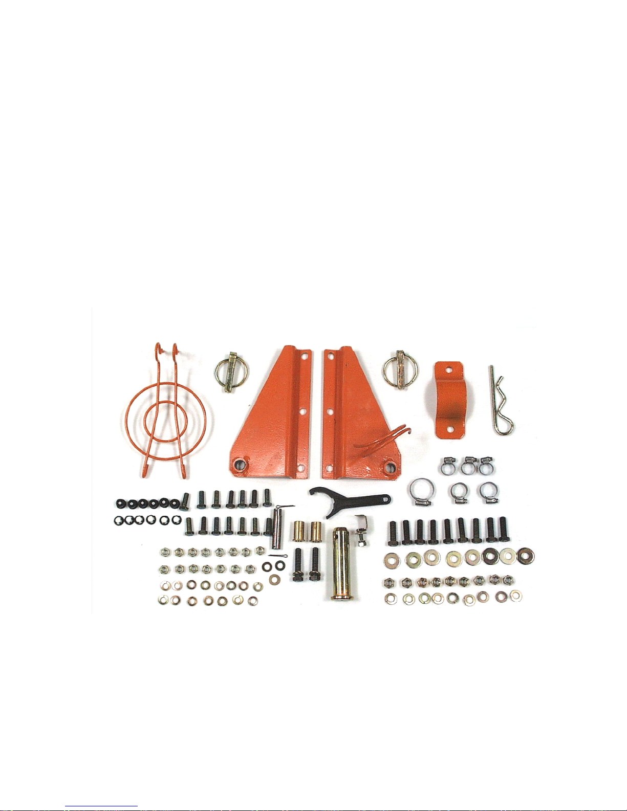
J600 CHT Assembly
1) Remove the sprayer and components from the crate it was shipped in. In the crate
you will find the following components to assemble: main outlet duct, stationary
duct, control valve, vertical hydraulic cylinder and brackets, clean water tank and
bracket, side step, auxiliary ducts and JA nozzles, fan cage cover for disconnect, and
accessory box with the required fasteners to assembly the sprayer.
Accessory Box
The above picture shows the parts that you will find inside the accessory box. The
hardware will be used in the assembly of the sprayer. You will also notice that there
is 2 vertical cylinder brackets, pivot bushings for duct, pin for vertical cylinder, fan
disconnect cover, plate for attaching the fresh water tank bracket, 6 JA nozzles with
swirl cores, hose retaining clip, spanner wrench, and pins for your convenience when
attaching the sprayer to the tractor. You will also find the operator’s manual.
03/23/05 J600CHT Assembly – DRAFT Prepared for Jacto
Service Seminar 3/2005
DRAFT COPY
Page 2
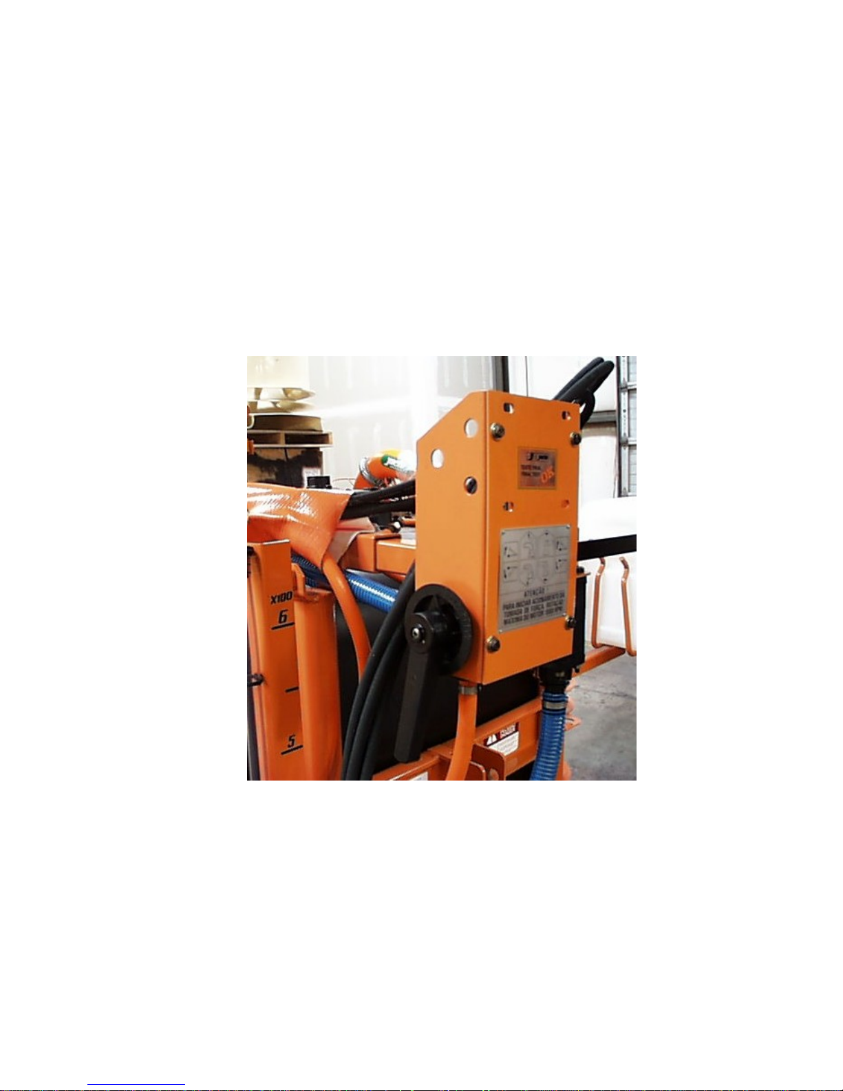
Control Valve
1) Install control valve into bracket (make sure hoses are routed on top of the tank
towards the center) as shown below. Install the blue return hoses and clamps to the
control valve. Note the hose coming from the centrifugal pump connects to bottom
outlet of control valve and the other two hoses that go to the top of the tank connect to
the upper fittings on the valve. Using a liquid dish soap will help to install the hoses
to the valve.
03/23/05 J600CHT Assembly – DRAFT Prepared for Jacto
Service Seminar 3/2005
DRAFT COPY
Page 3
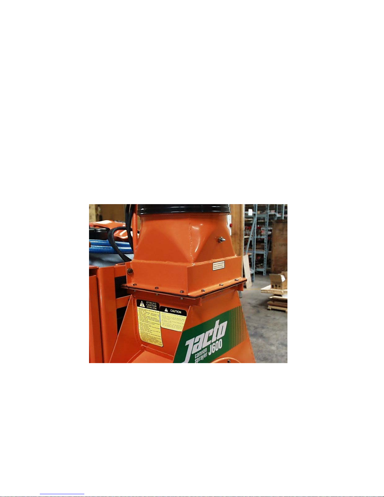
Stationary Duct Assembly
1) Install the stationary duct on the top of the fan housing. It is recommended the 4
bolts that attach the stationary duct to the frame be installed first to help align the
other 12 holes around the flange of the duct. Please note two of the 4 bolts need to be
installed from the inside of the duct opening to the frame. It may be difficult to align
the remaining holes and in some instances loosening the bolts that hold the fan
housing to the frame may be necessary. The duct flange bolts can usually be threaded
into the holes to help with alignment. You will notice one bolt is inserted into the
flange from the factory due to the fact the horizontal cylinder is already installed and
does not allow this bolt to be removed. The picture below shows the proper
positioning of the stationary duct.
03/23/05 J600CHT Assembly – DRAFT Prepared for Jacto
Service Seminar 3/2005
DRAFT COPY
Page 4
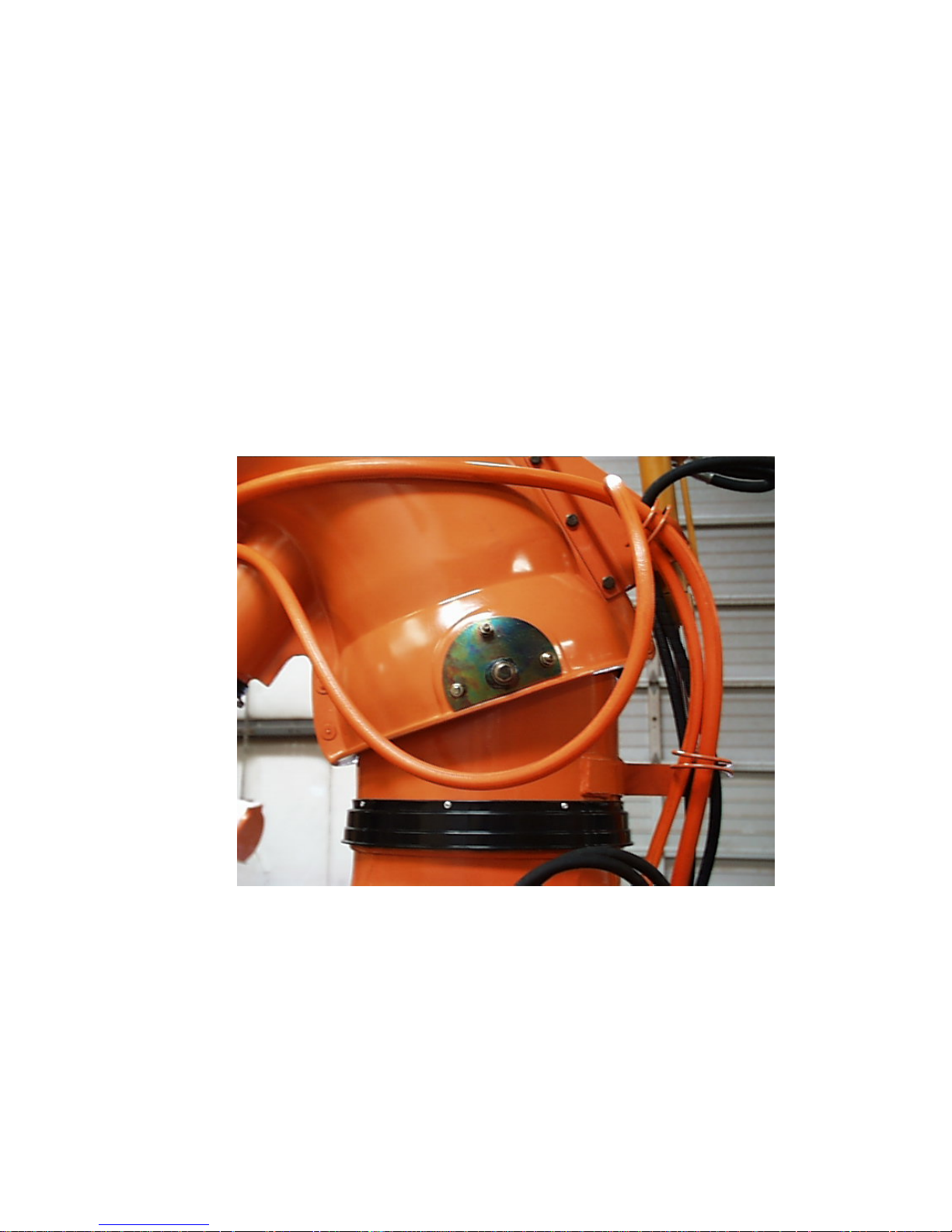
Movable Duct Assembly
1) Position the upper duct onto the stationary duct with the duct facing towards the
rear of the sprayer. Align the two holes in the duct with the bushing holes in the
stationary duct and insert the bushings supplied into the pivot holes. The bushing
must seat properly into the recess in the stationary duct holes or the duct will not
move up and down freely. Next install the two bolts through the bushings while
making sure the bushings stay aligned and then tighten the bolts.
03/23/05 J600CHT Assembly – DRAFT Prepared for Jacto
Service Seminar 3/2005
DRAFT COPY
Page 5
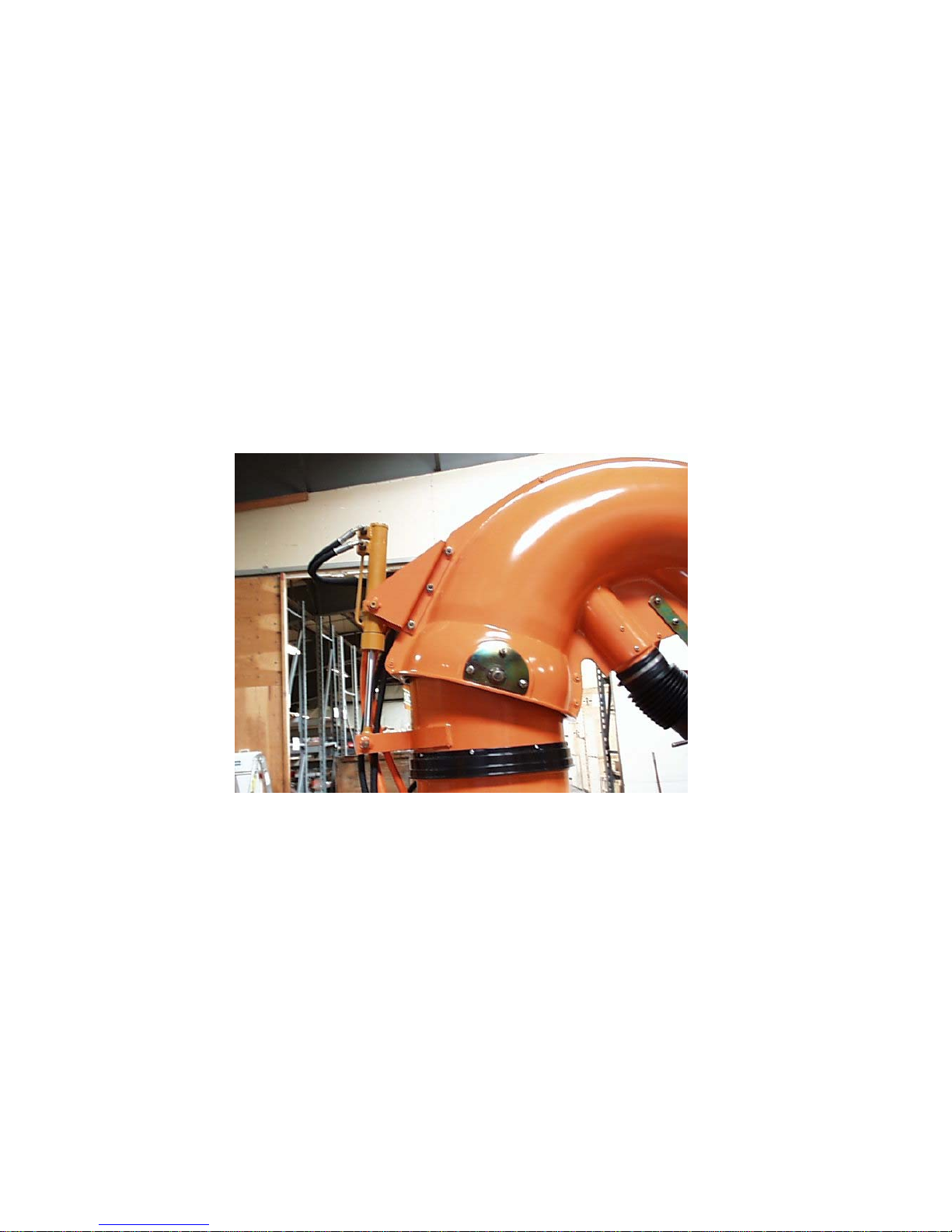
Hydraulic Cylinder Assembly
1) Install the vertical hydraulic cylinder to the movable duct by first installing the
pin that attaches it to the stationary duct. Next install the two brackets with the pins
on the cylinder inserted into the holes on the brackets. Pay close attention to the
positioning of the two brackets as shown below and install the three mounting bolts.
Be careful not to over tighten these bolts or damage to the duct may occur. Install the
paired hydraulic hoses to both the horizontal and the vertical cylinders and route them
through the loops and then through the orange sheath going up to the control valve.
03/23/05 J600CHT Assembly – DRAFT Prepared for Jacto
Service Seminar 3/2005
DRAFT COPY
Page 6
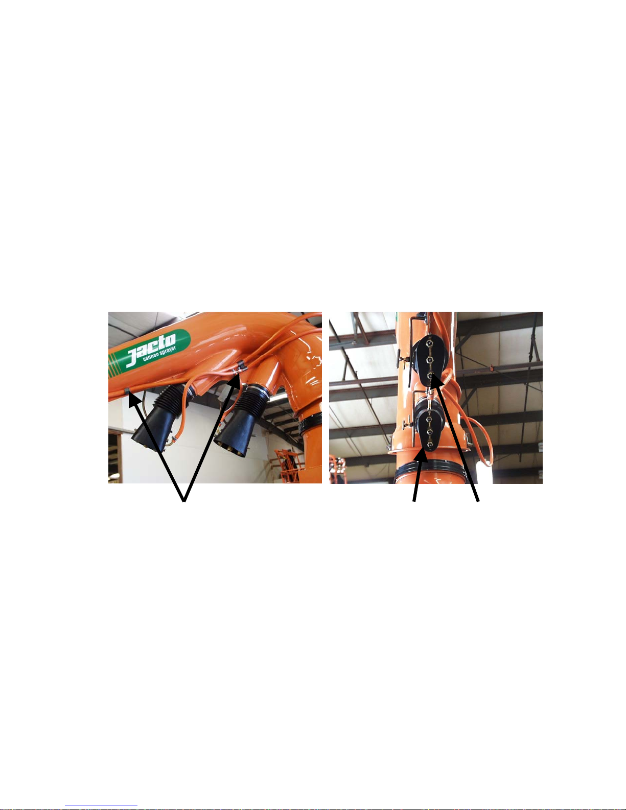
Auxiliary Duct Assembly
1) Install the two auxiliary ducts onto the movable duct with clamps as shown
below. Next install the hoses that connect to the main duct nozzle and auxiliary duct
nozzles and tighten the hose clamps. Route the two supply hoses through the hose
retainer clips on the duct and tighten. These two hoses should then be routed through
the hose loops on the back of the duct and then threaded into the orange sheath up to
the control valve and the ends installed onto the control valve. The 6 JA nozzles and
swirl cores need to be installed on the auxiliary duct nozzle branches by removing the
nozzle caps and removing the protective disc and inserting the nozzle filter, nozzle
and swirl core.
Retainer Clips
Auxiliary Duct
Nozzle Branches
03/23/05 J600CHT Assembly – DRAFT Prepared for Jacto
Service Seminar 3/2005
DRAFT COPY
Page 7
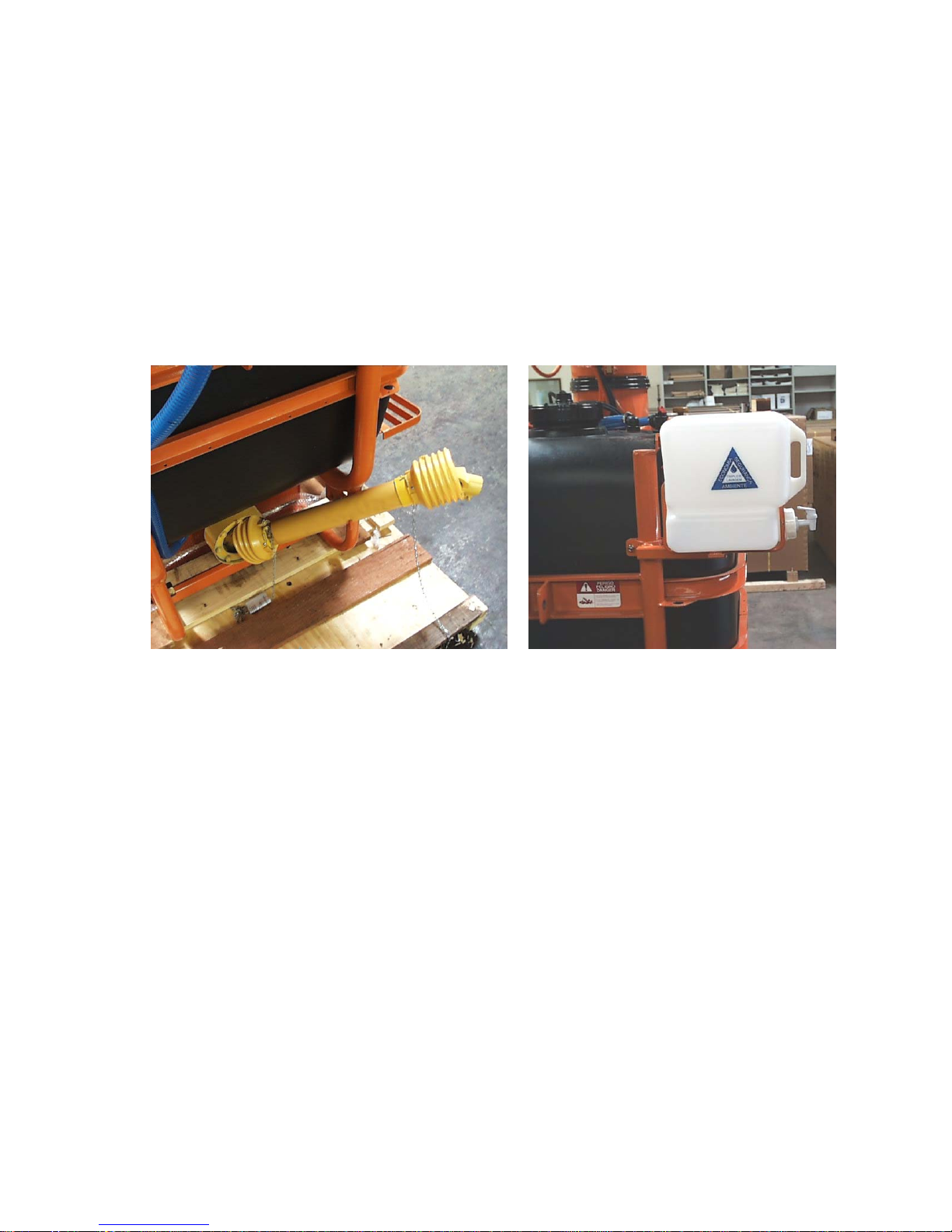
PTO Shaft and Clean Water Tank
1) Install the PTO shaft by sliding the implement end over the drive shaft and
aligning the key way with the key. Install the retaining bolt and tighten.
2) Install the clean water tank bracket onto the left frame post as shown below.
Install the clean water tank into the bracket.
03/23/05 J600CHT Assembly – DRAFT Prepared for Jacto
Service Seminar 3/2005
DRAFT COPY
Page 8
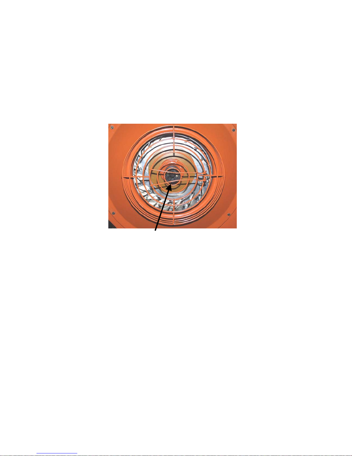
Final Assembly and Setup Tips
1) Install the side step to the holes located on the left lower portion of the frame
using the three bolts supplied.
2) Install the center piece for the fan cage for the fan disconnect and crimp the end
onto the fan cage to keep the center piece from coming loose.
3) Perform final inspection of hose clamps, fittings and fasteners to make sure they
are tightened properly. Also check oil level in gear box.
4) Attach sprayer to the tractor’s three point hitch. DO NOT attach PTO shaft to
tractor’s PTO drive until the PTO shaft has been cut to the proper length. To
determine the proper length required for the tractor being used the operator must lift
the sprayer until the shortest distance between the sprayer’s drive shaft and the
tractor’s PTO drive shaft is obtained. The PTO shaft should have 1 ¼ inch of free
play at this point. Measure the PTO shaft and cut both ends equally to achieve the
free play indicated above.
5) Add water to tank. Prime pump by removing the cap on the three way valve,
located toward the bottom of the sprayer, and turn the valve handle to allow water to
flow for 1 second to bleed out any air. Return the valve back to the operating
position.
6) Make sure fan disconnect is engaged before spraying. NEVER attempt to engage
or disengage fan disconnect when fan is turning.
7) Engage PTO shaft with tractor RPM at low speed and then raise RPM until you
reach 540 RPM at PTO.
03/23/05 J600CHT Assembly – DRAFT Prepared for Jacto
Service Seminar 3/2005
DRAFT COPY
 Loading...