

Page 1
FALCON
VORTEX/HORTI
English version - MI_USA-0160
WARNING
Read Operator's Manual before setting up, operating, or maintaining
sprayer . Failure to follow safety precautions in this manual an in labels
on the product could result in serious injury or death to the operator or
bystanders.
Keep manual nearby for futher reference. If manual is demaged or
illegible, contact your Jacto dealer or Jacto at the address below for a
replacement.
EDITION - 10/2012
CODE - 512194
Operator ’s Manual
JACTO INC.
th
19217 SW 1 19
Tualatin, Oregon 97062
T el.: (503) 885-8723
Fax: (800) 51 1-3671
Toll Free: (800) 522-8610
E-mail: [email protected]
Home page: www.jacto.com
Ave
Page 2

Page 3

INTRODUCTION
The agrochemicals application is necessary to achieve higher and economical production.
However, as it is a work that can bring risks to the human being, environment and crops, Jacto
has always been concerned with the proper use of its spraying machineries in an efficient
and safe way.
Therefore, read carefully and understand thoroughly this manual before operating this sprayer
and keep it always at hand when handling this sprayer for quick consult in case you are not quite
sure of some operation or adjustment.
Should your doubt persist, please contact your Jacto dealer.
MÁQUINAS AGRÍCOLAS JACTO S.A.
CONTRIBUTING TO THE AGRICULTURE DEVELOPMENT.
IDENTIFICATION PLATE
Your sprayer has a plate showing its model and serial number.
This information is very important so that Jacto can keep records of eventual modifications
made on the material used and on its construction characteristics.
In requesting replacement parts or maintenance, always specify the model and serial number
of your sprayer for prompt and efficient service.
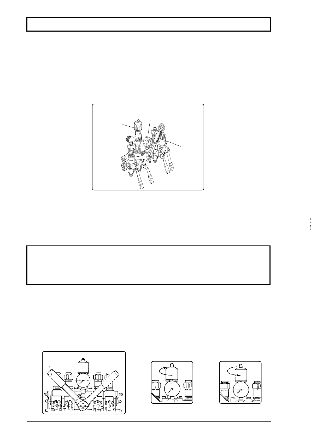
JACTO and FALCON are trademarks registered by Máquinas Agrícolas Jacto S.A.
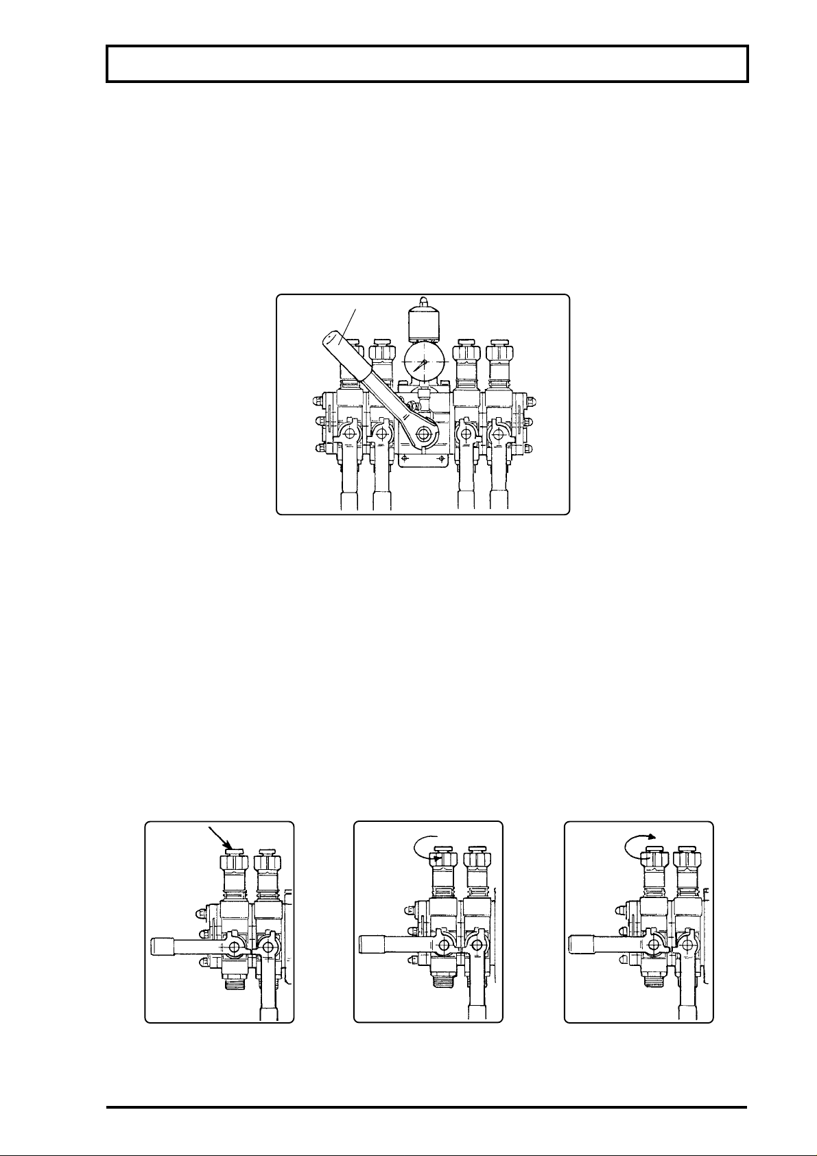
JACTO RESERVES THE RIGHT TO CHANGE SPECIFICATIONS AND DESIGN
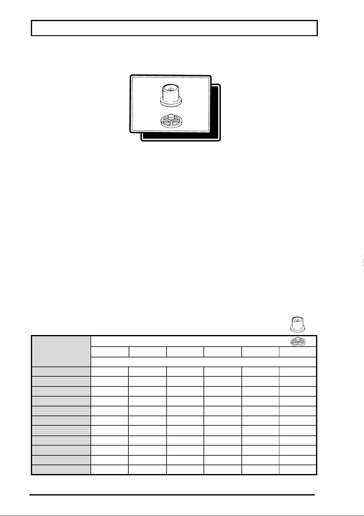
WITHOUT PRIOR NOTICE.
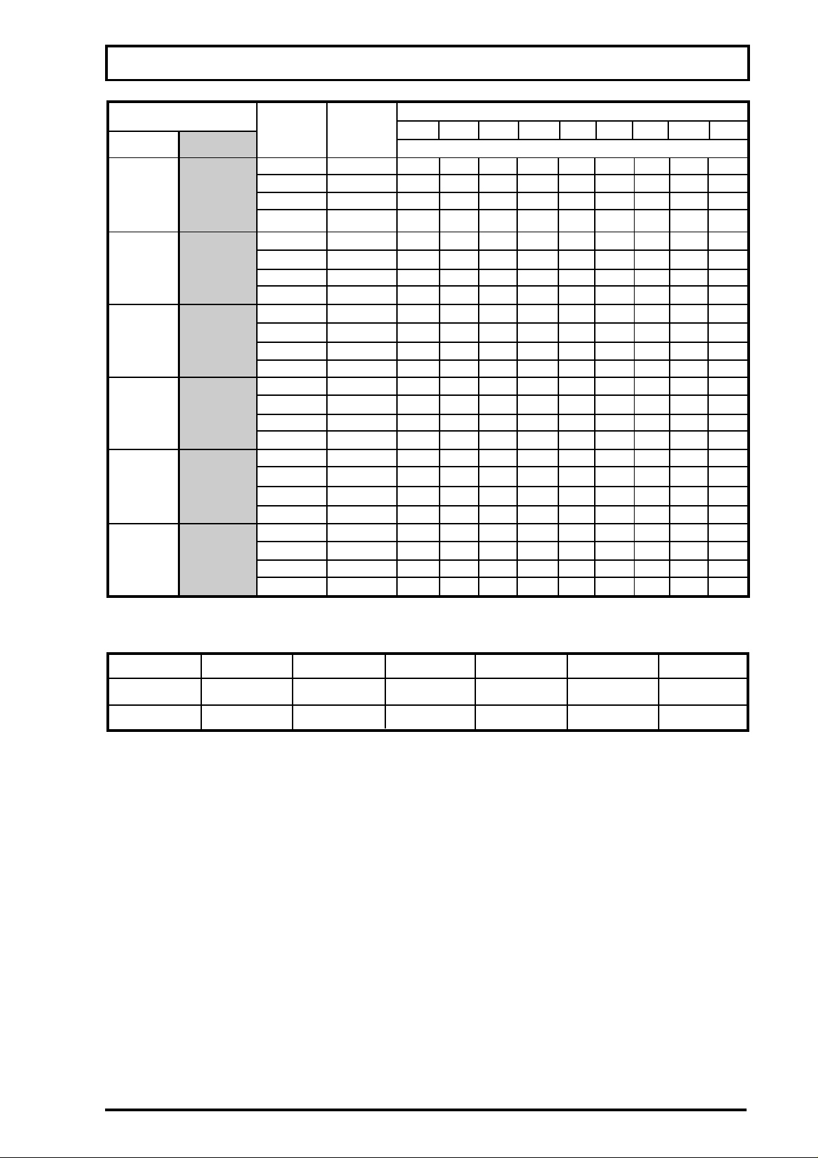
3
Page 4

TABLE OF CONTENTS
SAFETY PRECAUTIONS
Handling agricultural sprayers....................................................................................... 05
Handling chemical products .......................................................................................... 06
Decals............................................................................................................................. 07
Safety measures............................................................................................................. 09
TECHNICAL SPECIFICATIONS
FALCON VORTEX (with 13.77 in nozzle spacing)...................................................... 10
FALCON VORTEX (with 19.68 in nozzle spacing)...................................................... 11
FALCON VORTEX HORTI (with 13.77 in nozzle spacing).......................................... 12
FALCON VORTEX HORTI (with 19.68 in nozzle spacing).......................................... 13
MAIN COMPONENTS OF SPRAYER
Suction filter.................................................................................................................... 16
Chemical pump............................................................................................................... 16
Pressure regulators........................................................................................................ 17
Hydraulic boom control .................................................................................................. 18
Movement sensor ........................................................................................................... 21
Nozzles ............................................................................................................................ 21
Clean water tank (for washing hands) .......................................................................... 22
PTO shaft ........................................................................................................................ 22
Boom joint....................................................................................................................... 22
In-line filter....................................................................................................................... 22
Low pressure gauge kit ................................................................................................. 23
Foam marker (optional) ................................................................................................. 23
Chemicals mixer............................................................................................................. 25
Mixing chemicals............................................................................................................ 25
Chemical container rinse nozzle................................................................................... 26
Flow bypass valve .......................................................................................................... 27
Hydraulic agitator ........................................................................................................... 27
Filler unit (optional) ........................................................................................................ 28
Fan rotation adjusting valve........................................................................................... 29
Spray boom..................................................................................................................... 29
OPERATIONAL PROCEDURES....................................................................................... 30
SETTING UP THE TRACTOR............................................................................................ 31
CONNECTING THE PTO ................................................................................................... 33
ASSEMBLING THE ELECTRO-ELECTRONIC CONTROL ............................................ 34
ASSEMBLING THE BOOM................................................................................................ 35
BOOM UNFOLDING AND FOLDING ................................................................................ 41
OPERATION AND ADJUSTMENTS
Spray application technology ........................................................................................ 43
Pressure regulator.......................................................................................................... 44
Nozzles ............................................................................................................................ 46
Calibrating the sprayer .................................................................................................. 50
Diluting the chemicals.................................................................................................... 52
MAINTENANCE
Guidelines ....................................................................................................................... 53
Components.................................................................................................................... 53
Lubrication table............................................................................................................. 56
Lubrication points........................................................................................................... 56
PTO shaft ........................................................................................................................ 59
Winter storage ................................................................................................................ 60
Trouble-shooting ............................................................................................................. 61
GENERAL CARE
Handling agricultural sprayers and chemicals
After spraying .................................................................................................................
Warranty Statement ...................................................................................................... 65
............................................................. 64
6
4
4
Page 5
SAFETY INSTRUCTIONS
HANDLING AGRICULTURAL SPRAYERS
OWNER / OPERATOR:
This sprayer was carefully designed and built so
as to give you the maximum production, saving, easy
operation and safety.
Therefore, you or anyone else who is going to
operate, maintain and work around this sprayer must
read and understand this manual thoroughly in order to
be familiar with all the operating and maintenance
procedures and safety information related to this
sprayer. All accidents can be prevented if all the safety
instructions are correctly followed.
Moreover, always keep this manual at hand for
quick review in case of doubt.
ATTENTION
FAILURE TO FOLLOW THE SAFETY
INSTRUCTIONS PROPERLY WILL RISK YOUR
OWN LIFE AS WELL AS THE LIFE OF PEOPLE
WORKING AND LIVING AROUND YOU.
This safety alert symbol identifies important safety messages.
When you see it, be alert to any possibility of personal injury or death.
Keep all the decals on the sprayer and replace them if missing or
illegible.
- Before operating this sprayer, read carefully and understand thoroughly this manual.
- Do not allow untrained people to operate this sprayer because this can cause serious injuries or
fatal accidents.
- Do not modify this sprayer in any way because this can impair the function and risk your safety.
- Keep away children, aged people and animals while operating, servicing this sprayer and even
when the sprayer is stored.
- In the delivery of your sprayer, have your Jacto dealer instruct you on the assembly, operation,
maintenance and warranty in detail.
- Keep hands, feet and clothing away from moving parts.
- Never use loose clothing or mittens while working around the sprayer.
- Do not travel at high speeds.
- Always stop tractor engine, disengage the PTO and wait for all moving parts to stop
before servicing, adjusting or repairing the sprayer.
ATTENTION: Do not touch PTO shafts, belts, fans or any other moving part while the
sprayer is running.
- Only unhitch the sprayer on firm and level ground.
- Keep your sprayer in thorough repair.
5
Page 6
SAFETY INSTRUCTIONS
HANDLING CHEMICALS
Chemical products are classified in four categories of toxicity. According to their toxicity level,
there is a special recommendation of appropriate protective equipment.
As your safety concerns first, we list below all the protective equipment recommended for
handling chemical products of the category 1 which includes high toxicity level chemicals.
This way, all the possibilities of serious illness and death are eliminated.
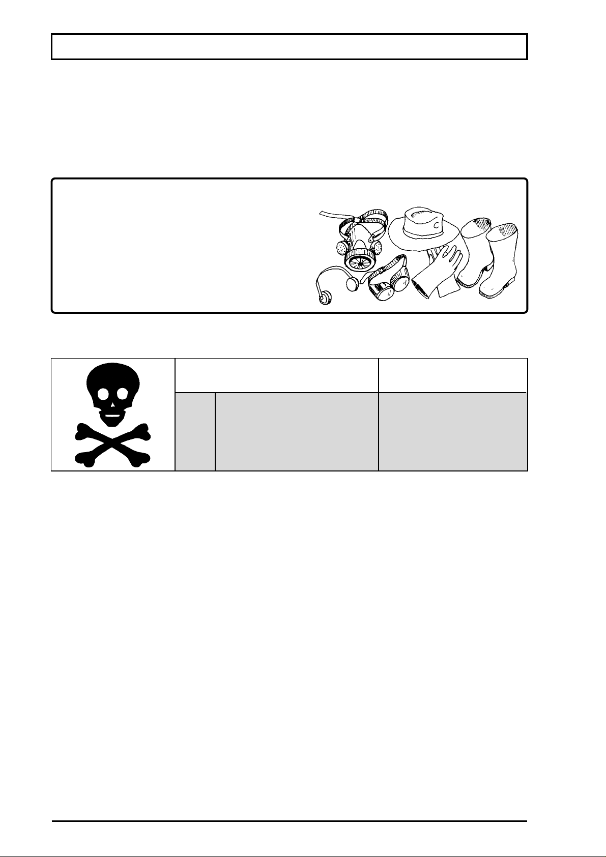
Obligatory individual protective equipment for handling and spraying chemicals:
- Long-sleeved working clothes
- Impermeable apron or coverall
- Impermeable gloves
- Impermeable wide-brimmed hat
- Boots
- Special protective masks equipped with
appropriate filters for each type of product
CHEMICAL PRODUCTS CLASSIFICATION
LABEL COLOR ON
CHEMICALS CONTAINER
RED
YELLOW
BLUE
GREEN
III
IV
TOXICITY LEVEL
I
II
HIGH
MODERATE
LOW
LIGHT
DIRECTIONS
- Read and follow all instructions on the chemicals manufacturer's label.
- Keep the chemical products closed and in a dry and ventilated place.
- Use the chemical products in agriculture only.
- Keep away children, untrained people and animals.
- Handle the chemicals following recommendations of a technician.
- Always handle chemicals in a ventilated place and equipped with individual protective equipment.
- Use the application rate as per instructions on the labels.
- Do not make spray applications in the wind or hot weather.
- Do not drink, eat or smoke while spraying or handling chemicals.
- Keep children, untrained people and animals away from the application areas.
- Never blow through nozzles strainers, valves or pipelines by mouth.
- Do not store or transport chemical products together with food, medicines, people, animals.
- Make sure rivers, lakes, etc. will not be contaminated when washing out the sprayer.
- After spraying, take off all protective clothing and take a shower.
- In case of intoxication, go see a doctor immediately and show him the chemical products label.
- Never medicine an unconscious person through mouth.
- Do not re-use the chemical products containers for other purposes. Consult an
agronomist on how to discard empty containers of chemical products.
6
Page 7

SAFETY INSTRUCTIONS
DECALS
Safety decals are placed on the equipment to reduce the risk of damages or accidents to
the operator or to the equipment during the use.
Before operating the equipment, identify and understand the mean of all decals, through
this page.
Keep them in good repair, clean and legible. Replade them immediately in case of damage
by ordering them through the part numbers specified below.
P/N: 276220
P/N: 395061
ATTENTION: Read the
operator's manual before
operating the sprayer.
ATTENTION: Lubrication
point
ATTENTION: Lubrication
point with oil.
ATTENTION: Drain point.
P/N: 389387
ATTENTION: Clean water tank
to wash the hands.
P/N: 379073
P/N: 379248
P/N: 379131
P/N: 379230
ATTENTION: Hydraulic oil
level indicator.
P/N: 379107
ATTENTION: Obligatory use
of protective clothing.
ATTENTION: Obligatory use
of hearing protector.
ATTENTION: Read the
operator's manual before
operating the sprayer.
P/N: 379123
7
Page 8

SAFETY INSTRUCTIONS
P/N: 379008
P/N: 379065
ATTENTION: Risk of serious
injuries. Do not make any
operation on the PTO shaft if
the PTO is engaged.
ATTENTION: Risk of serious
injuries. Keep all protection
devices in its places.
ATTENTION: Risk of serious
injuries. Do not maneuver the
sprayer close to electricity supply
cables.
P/N: 378992
ATTENTION: Obligatory use
of protective mask.
P/N: 379115
P/N: 379040
P/N: 379057
ATTENTION: Risk of injuries.
Keep away from the sprayer
when it is running.
ATTENTION: Risk of serious
injuries. Keep away and do not
make any kind of maintenance
while the fan is in motion and
the PTO is engaged.
Identification
plate
ATTENTION: Maximum speed
allowed for the machine is 18.5
mph .
P/N: 379214
ATTENTION: This machine is
not allowed in highways.
P/N: 379222
Final test of the equipment.
P/N: 013169
P/N: 997841
Decal do not step on
P/N: 958629
8
Page 9
SAFETY INSTRUCTIONS
ATTENTION: THIS SAFETY ALERT SYMBOL IDENTIFIES IMPORTANT
SAFETY MESSAGES. WHEN YOU SEE IT, BE ALERT TO ANY POSSIBILITY
OF PERSONAL INJURY OR DEATH.
SAFETY MEASURES
- Keep all the protectors on their proper places.
- Remove the controls installed on the tractor before disconnecting the sprayer.
- Do not operate the pump without liquid.
- Clean and lubricate regularly the male and female parts of the PTO shaft to reduce the friction
between them.
- Lubricate daily the grooved shaft of the tractor's PTO.
- Keep the hands, feet and clothes away from PTO shafts and any type of transmission, once
they can cause serius injuries, even death.
- Never operate the sprayer if the PTO shaft, the sprayer and the tractor's PTO protectors are
not in their proper place.
- Do not exceed 580 rpm at the PTO.
- The PTO shaft protector must always remain in good repair and fastened by the belts. The
PTO shaft must work freely in its interior.
- The PTO shaft coupling ends must be locked on the tractor's PTO and sprayer's shaft.
- Make sure the drawbar and the sprayer end are properly engaged .
- Follow these recommendations strictly in order to avoid injuries or death .
- Check and change the worn and broken parts. Check if all protectors are in their places
before operating the sprayer.
- Make sure that no one is close to the machine before running the engine.
- Stop the engine before leaving the operator's position to adjust, clean or lubricate, save other
recommendation indicated on the operator's manual.
- Stop the machine and all moving parts before adjusting, maintenance or when there are people
close to the equipment.
- Do not go up on the sprayer when it is in motion.
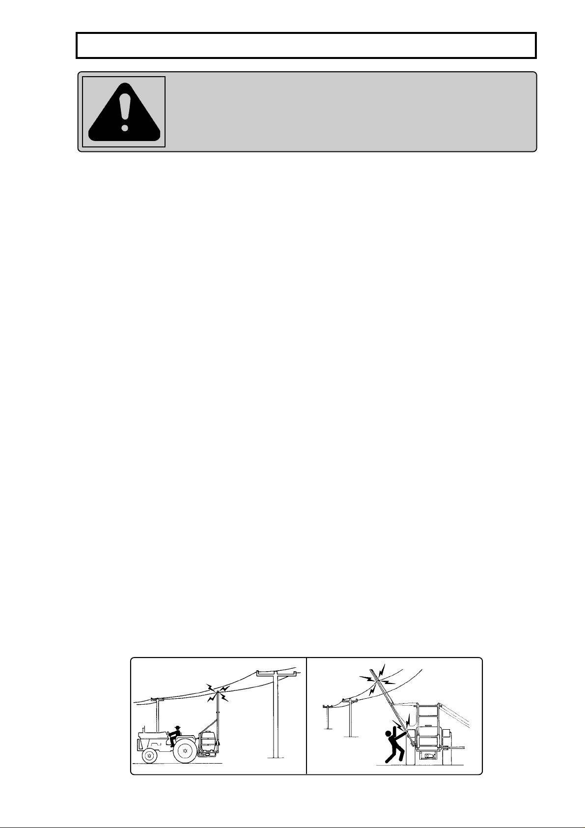
ELECTRICITY SUPPLY CABLES
- Attention when passing next or under an electricity supply cables. In case of doubt, change
the course.
- Never fold and unfold the booms close to the electricity supply cables.
- The sprayer must be trailed by the tractor in the farm with the spray booms folded and locked.
Always place the sliding frame at the lowest position (rest position of the fixed frame).
- Remove the booms of the sprayer before transporting it by wagons, trucks or trailers.
9
Page 10

TECHNICAL SPECIFICATIONS
FALCON VORTEX (with 13.77 in nozzle spacing)
TECHNICAL SPECIFICATIONS
Length (in) ............................................................................... 65.74
Width (in)................................................................................. 96.45
Height (in) 111.02 (without boom)
129.52 (with folded boom)
Weight (lb)............................................................................... 1609.37 (with full oil tank)
Tank
- Capacity (gallons)................................................................. 158.50
- Material ................................................................................. Polyethylene
Filter
- Model .................................................................................... FVS-100
- Mesh ..................................................................................... 60
Pump
- Model .................................................................................... JP-75
- Capacity (gpm)..................................................................... 19.81
- Maximum working pressure (kgf/cm² - psi) .......................... 28 - 400
................................................................................................ NOTE: Maximum allowed on this
................................................................................................ sprayer: 150 psi (10.5 kgf/cm²)
- Power consumption (HP) ..................................................... 2.3 with the pump at 150 psi
Pressure gauge
- Model .................................................................................... With extended scale
Control
- Model .................................................................................... Masterflow
Nozzles
- Type...................................................................................... Bijet double nozzle holder
- Quantity ................................................................................ 82
- Model .................................................................................... JA-2 (cone) / AXI 110-02 (flat fan)
- Recommended maximum pressure (kgf/cm² - psi) ............. JA-2 (10.5 - 150) / AXI-02 (4.2 - 60)
- Spacing (in) .......................................................................... 13.77
Boom
- Length (ft) ............................................................................. 45.93
- Actuation............................................................................... Hydraulic
- Height (ft) .............................................................................. 1.64 to 4.26
Level indicator.......................................................................... Hose attached to the tank
Agitation ................................................................................... Hydraulic system with venturi
Filler unir (OPTIONAL)
- Model .................................................................................... EJ-250
Fan
- Rotation (rpm) ...................................................................... 2,800
- Air volume (ft³/min) ............................................................... 18,822.72 (32,000 ft³/h)
- Air speed (mph).................................................................... 62 (w/ boom at the lowest position)
- Power consumption (HP) ..................................................... 21.3
Hydraulic pump
- Capacity (gpm)..................................................................... 13.20
- Rotation (rpm) ...................................................................... 2,250
- Oil type.................................................................................. ISO VG-68
- Oil reservoir capacity (gallons) ............................................. 11.68
Maximum power consumption (HP) ........................................ 23.6
RECOMMENDED TRACTOR ............................................... 80 HP
Recommended maximum working speed (mph).................... 6.5
10
Page 11

TECHNICAL SPECIFICATIONS
FALCON VORTEX (with 19.68 in nozzle spacing)
TECHNICAL SPECIFICATIONS
Length (in) ............................................................................... 65.74
Width (in)................................................................................. 96.45
Height (in) 111.02 (without the boom)
129.52 (with folded boom)
Weight (lb)............................................................................... 1,609.37 (with full oil tank)
Tank
- Capacity (gallons)................................................................. 158.50
- Material ................................................................................. Polyethylene
Filter
- Model .................................................................................... FVS-100
- Mesh ..................................................................................... 60
Pump
- Model .................................................................................... JP-75
- Capacity (gpm)..................................................................... 19.81
- Maximum working pressure (kgf/cm² - psi) .......................... 28 - 400 NOTE: maximum allowed
................................................................................................ on this sprayer:150 psi (10.5 kgf/cm²)
- Power consumption (HP) ..................................................... 2.3 with the pump at 150 psi
Pressure gauge
- Model .................................................................................... with extended scale
Control
- Model .................................................................................... Masterflow
Nozzles
- Type...................................................................................... Bijet double nozzle holder
- Quantity ................................................................................ 58
- Model .................................................................................... JA-2 (cone) / AXI 110-02 (flat fan)
- Recommended maximum pressure (kgf/cm² - psi) ............. JA-2 (10.5 - 150) / AXI-02 (4.2 - 60)
- Spacing (in) .......................................................................... 19.68
Boom
- Length (ft) ............................................................................. 14.0
- Actuation............................................................................... Hydraulic
- Height (ft) .............................................................................. 1.64 to 4.26
Level indicator.......................................................................... Hose attached to the tank
Agitator .................................................................................... Hydraulic system with venturi
Filler unit (OPTIONAL)
- Model .................................................................................... EJ-250
Fan
- Rotation (rpm) ...................................................................... 2,800
- Air volume (ft³/min) ............................................................... 18,822.77 (32,000 ft³/h)
- Air speed (mph).................................................................... 62 (w/ boom at the lowest position)
- Power consumption (HP) ..................................................... 21.3
Hydraulic pump
- Capacity (gpm)..................................................................... 13.20
- Rotation (rpm) ...................................................................... 2,250
- Oil type.................................................................................. ISO VG-68
- Oil reservoir capacity (gallons) ............................................. 11.88
Maximum power consumption (HP) ........................................ 23.6
RECOMMENDED TRACTOR ............................................... 80 HP
Recommended maximum working pressure (mph) ............... 6.5
11
Page 12

TECHNICAL SPECIFICATIONS
FALCON VORTEX HORTI (with 13.77 in nozzle spacing)
TECHNICAL SPECIFICATIONS
Length (in) ............................................................................... 65.74
Width (in)................................................................................. 96.45
Height (in) 111.02 (without boom)
129.52 (with folded boom)
Weight (lb)............................................................................... 1609.37 (with full oil tank)
Tank
- Capacity (gallons)................................................................. 158.50
- Material ................................................................................. Polyethylene
Filter
- Model .................................................................................... FVS-100
- Mesh ..................................................................................... 60
Pump
- Model .................................................................................... JP-75
- Capacity (gpm)..................................................................... 19.81
- Maximum working pressure (kgf/cm² - psi) .......................... 28 - 400
- Power consumption (HP) ..................................................... 5.3 with the pump at 400 psi
Pressure gauge
- Model .................................................................................... With extended scale
Control
- Model .................................................................................... Masterflow
Nozzles
- Type...................................................................................... Bijet double nozzle holder
- Quantity ................................................................................ 82
- Model .................................................................................... JA-2 (cone) / AXI 110-02 (flat fan)
- Recommended maximum pressure (kgf/cm² - psi) ............. JA-2 (10.5 - 150) / AXI-02 (4.2 - 60)
- Spacing (in) .......................................................................... 13.77
Boom
- Length (ft) ............................................................................. 45.93
- Actuation............................................................................... Hydraulic
- Height (ft) .............................................................................. 1.64 to 4.26
Level indicator.......................................................................... Hose attached to the tank
Agitation ................................................................................... Hydraulic system with venturi
Filler unir (OPTIONAL)
- Model .................................................................................... EJ-250
Fan
- Rotation (rpm) ...................................................................... 2,800
- Air volume (ft³/min) ............................................................... 18,822.72 (32,000 ft³/h)
- Air speed (mph).................................................................... 62 (w/ boom at the lowest position)
- Power consumption (HP) ..................................................... 21.3
Hydraulic pump
- Capacity (gpm)..................................................................... 13.20
- Rotation (rpm) ...................................................................... 2,250
- Oil type.................................................................................. ISO VG-68
- Oil reservoir capacity (gallons) ............................................. 11.68
Maximum power consumption (HP) ........................................ 26.6
RECOMMENDED TRACTOR ............................................... 80 HP
Recommended maximum working speed (mph).................... 6.5
12
Page 13

TECHNICAL SPECIFICATIONS
FALCON VORTEX HORTI (with 19.68 in nozzle spacing)
TECHNICAL SPECIFICATIONS
Length (in) ............................................................................... 65.74
Width (in)................................................................................. 96.45
Height (in) 111.02 (without the boom)
129.52 (with folded boom)
Weight (lb)............................................................................... 1,609.37 (with full oil tank)
Tank
- Capacity (gallons)................................................................. 158.50
- Material ................................................................................. Polyethylene
Filter
- Model .................................................................................... FVS-100
- Mesh ..................................................................................... 60
Pump
- Model .................................................................................... JP-75
- Capacity (gpm)..................................................................... 19.81
- Maximum working pressure (kgf/cm² - psi) .......................... 28 - 400
- Power consumption (HP) ..................................................... 5.3 with the pump at 400 psi
Pressure gauge
- Model .................................................................................... with extended scale
Control
- Model .................................................................................... Masterflow
Nozzles
- Type...................................................................................... Bijet double nozzle holder
- Quantity ................................................................................ 58
- Model .................................................................................... JA-2 (cone) / AXI 110-02 (flat fan)
- Recommended maximum pressure (kgf/cm² - psi) ............. JA-2 (10.5 - 150) / AXI-02 (4.2 - 60)
- Spacing (in) .......................................................................... 19.68
Boom
- Length (ft) ............................................................................. 14.0
- Actuation............................................................................... Hydraulic
- Height (ft) .............................................................................. 1.64 to 4.26
Level indicator.......................................................................... Hose attached to the tank
Agitator .................................................................................... Hydraulic system with venturi
Filler unit (OPTIONAL)
- Model .................................................................................... EJ-250
Fan
- Rotation (rpm) ...................................................................... 2,800
- Air volume (ft³/min) ............................................................... 18,822.77 (32,000 ft³/h)
- Air speed (mph).................................................................... 62 (w/ boom at the lowest position)
- Power consumption (HP) ..................................................... 21.3
Hydraulic pump
- Capacity (gpm)..................................................................... 13.20
- Rotation (rpm) ...................................................................... 2,250
- Oil type.................................................................................. ISO VG-68
- Oil reservoir capacity (gallons) ............................................. 11.88
Maximum power consumption (HP) ........................................ 26.6
RECOMMENDED TRACTOR ............................................... 80 HP
Recommended maximum working pressure (mph) ............... 6.5
13
Page 14

TECHNICAL SPECIFICATIONS
F ALCON 1400 AM-14 / F ALCON 1400 VORTEX
FOR FALCON 1400 AM-14 AND FALCON 1400 VORTEX
SPRAYERS:
• THE RECOMMEDED WORKING SPEED IS 5 MPH.
• THE TRACTORS TO BE USED ON THIS TYPE OF APPLICATIONS MUST HAVE
MINIMUM POWER OF 100 HP AND 4 X 4.
• THE FLOW RATE TO FILL THE SPRAYER MUST NOT EXCEED 280 LITERS/
MINUTE OR THE TIME TO FILL IT MUST TAKE AT LEAST 5 MINUTES.
• THE NONCOMPLIANCE WITH THE RECOMMENDA TIONS CAN CAUSE DAMAGES
TO THE EQUIPAMENT, AS WELL AS THE LOSS OF THE RIGHTS T O W ARRANTY
FOR NOT USING THE EQUIP AMENT ACCORDING TO THE TECHNICAL RECOMMENDA TIONS
OF THE OPERATOR'S MANUAL.
FALCON 1400 AM-14
14
FALCON 1400 VORTEX
Page 15
TECHNICAL SPECIFICATIONS
V.A.R
2 WAYS 4 WAYS
( Eletric JEC 3900)
CONTROLS
JEC 3600 and JSC 5000)
( Electro electrônic with
BIJET
BIJET
BIJET
BIJET
19.682913.77
41
JA-2 / AXI-100.02
19.682913.77
41
JA-2 / AXI-100.02
19.682913.77
41
JA-2 / AXI-100.02
19.682913.77
41
JA-2 / AXI-100.02
JP-75
19.81 gpm
JP-75
19.81 gpm
JP-75
19.81 gpm
JP-75
19.81 gpm
MASTERFLOW
BIJET
4 WAYS
AVAILABLE VERSIONS OF FALCON VORTEX
BIJET
2 WAYS
19.682913.77
JA-2 / AXI-100.02
19.682913.77
41
JP-75
41
JP-75
JA-2 / AXI-100.02
DESCRIPTION
19.81 gpm
19.81 gpm
FONTE LIMPA
WITH QUICK FITTING
JP-100
MODEL.........
MODEL........
FALCON VORTEX - OPTIONS
Nozzle holder......................
Nozzles
- Model (FALCON VORTEX)
- Spacing............................
- Quantity ............................
- Spacing............................
- Quantity ............................
Spray pump
- Model...............................
15
- Capacity...........................
FILLER UNIT .............................................
PUMP.........................................................
Page 16
MAIN COMPONENTS OF SPRAYER
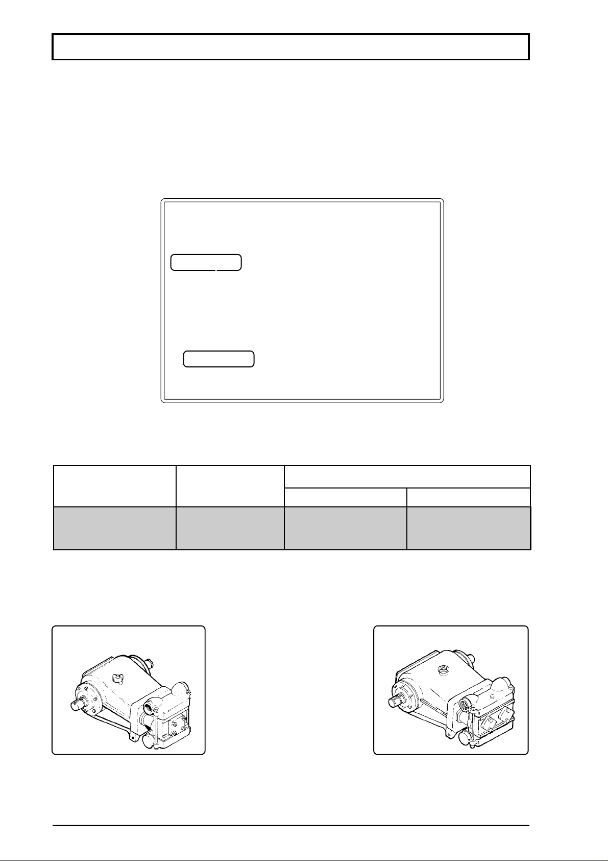
SUCTION FILTER
Located between the tank and pump, the suction filter is specifically designed to prevent dirt or
impurities from reaching the pump.
It has an easy-to-reach shut off valve which stops the liquid flow to allow filter cleaning, filtering
elements changing and/or pump maintenance.
This shut off valve must remain open while the sprayer is running. If it remains closed, you will hear
an unusual noise in the pump.
shut off valve
suction filter
SPRAY PUMP
The spray pumps used in the FALCON VORTEX sprayers have capacity ranging from 19.81
to 26.41 gpm gallons per minute.
SPRAY PUMP
MODEL
JP - 75
JP - 100
- Its ceramic sleeves ensure great resistance to abrasion and chemical action.
Piston cup replacement becomes easier by removing the head assembly in a quick and simple
operation, with no need to remove the pump.
JP-75
FLOW RATE
(gpm)
19.81
26.41
MAXIMUM WORKING PRESSURE
psi
300
300
JP-100 (Optional)
kgf/cm²
21
21
NOTE: Due to the characteristics of the chemical control, the maximum attained in the
pressure line on the FALCON VORTEX 10.5 kgf/cm² (150 psi).
16
Page 17
MAIN COMPONENTS OF SPRAYER
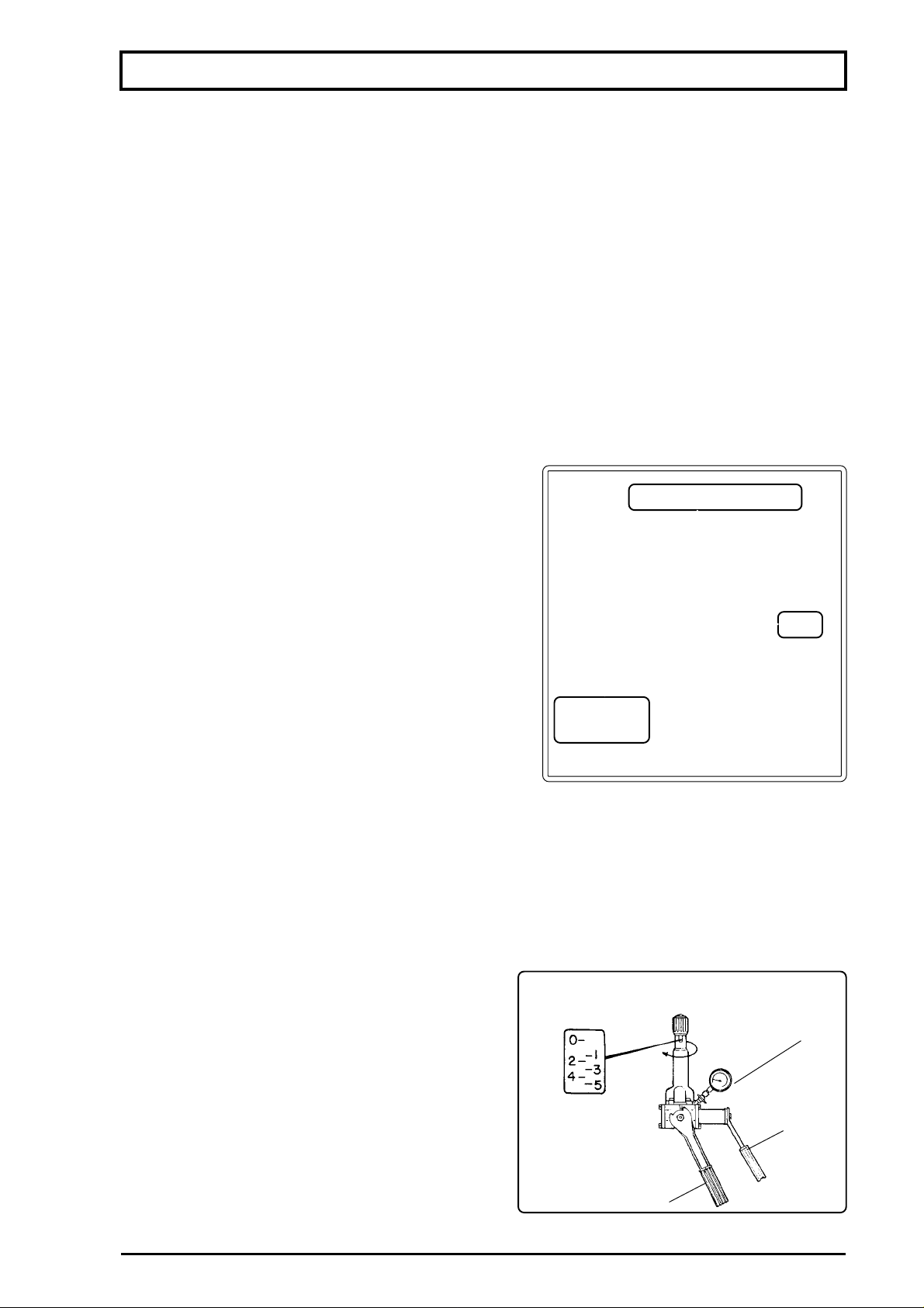
PRESSURE REGULATOR
MASTERFLOW CONTROL
This pressure regulator control provides great sensitivity and accuracy in the calibrations.
Besides, it has two basic functional characteristics in comparison with the conventional controls.
- FLOW PROPORTIONAL TO TRAVEL
The application rate remains unchanged per sprayed area even if the engine rotation fluctuates
within a same gear.
- CONSTANT WORKING PRESSURE ALONG THE WHOLE BOOM, REGARDLES OF THE
NUMBER OF BOOM SECTIONS TURNED ON
This control has a system that enables to calibrate the return of each boom section, thus
maintaining the same pressure in all sections, independent of the number of sections turned on or
off.
ATTENTION
To ensure longer life of the pressure gauge, close
MASTERFLOW control
the lever (1) after calibrating the sprayer, thus releasing
the pressure, and close the pressure gauge valve.
(1)
pressure
gauge
CONTROL V.A.R.
- This pressure regulator provides calibration randing from 2 to 35 kg/cm² (30 to 500 psi), indicated
by the pressure gauge.
The levers (1) and (2) have different jobs. The lever (1) turns on and off the chemical flow while the
lever (2) distributes the chemical flow to the right and left nozzles branches or the one only. This
makes applications easier and with less wastage of agrochemicals.
ATTENTION: In order to insure longer life of the
pressure gauge, close lever (1) after regulating the
sprayer, thus releasing the pressure, and close the
pressure gauge valve.
17
VAR
pressure
gauge
( 2 )
( 1 )
Page 18
MAIN COMPONENTS OF SPRAYER
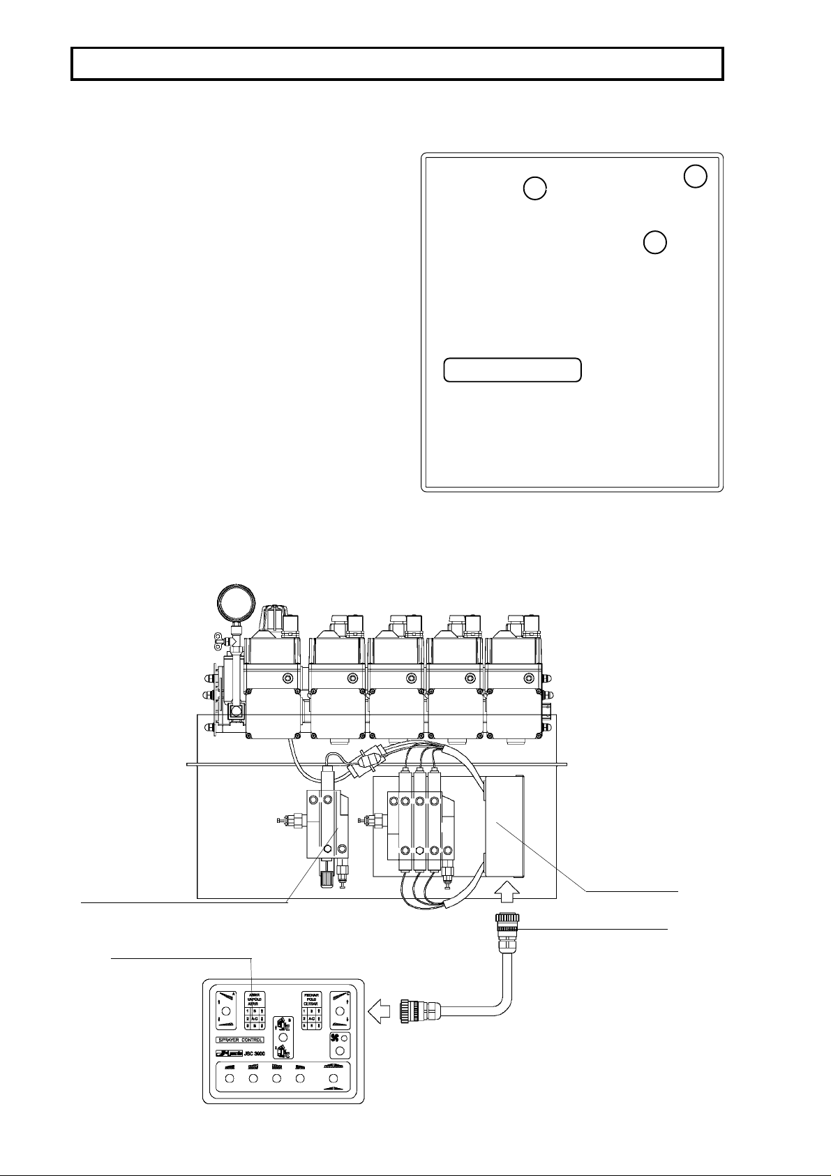
HYDRAULIC BOOM CONTROLS
BASIC CONTROL
This control is mounted to the tractor fender on
01
03
the most convenient position to the operator.
02
It comprise 3 levers:
- Lever 01: raises and lower the right boom.
- Lever 02: raises and lower the frame.
- Lever 03: raises and lower the left boom.
The boom can also be unfolded and folded
hydraulic boom control
through the hydraulic control.
JEC-3900 ELECTRIC CONTROL
Located under the spray control, the electric hydraulic boom control is connected to the distributing
box, which is connected to the control panel fastened near to the operator.
electric hydraulic boom control
control panel
distributing
box
cable
18
Page 19
MAIN COMPONENTS OF SPRAYER
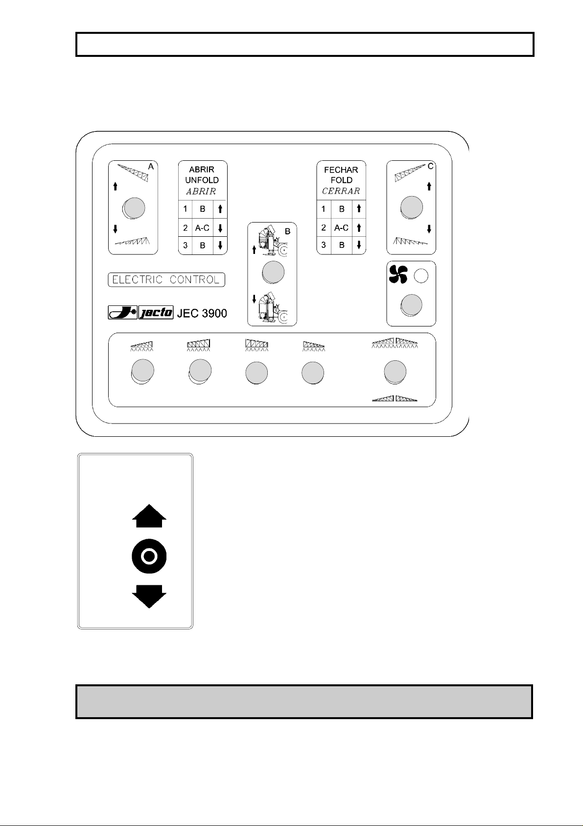
CONTROL PANEL
ELECTRIC HYDRAULIC BOOM CONTROL and SPRAYER CONTROL
A
1 2
Switch positions
ON
C
3 4
Switch A: raises and lower the right boom.
Switch B: raises and lower the left boom.
Switch C: raises and lower the frame.
Switch D: Turn on/off the fan.
5
B
D
SWITCH
Sprayer Control
Switch 1: turns on the spray to the 2nd section of the right
boom.
Switch 2: turns on the spray to the 1st section of the right
boom.
Switch 3: turns on the spray to the 1st section of the left
OFF
NOTE: To actuate the switches 1, 2, 3 or 4, the switch 5 must be on (upward).
boom.
Switch 4: turns on the spray to the 2nd section of the left
boom.
Switch 5: directs the flow to the booms or to the tank (return).
19
Page 20

MAIN COMPONENTS OF SPRAYER
ELECTRIC-ELECTRONIC MSTERFLOW CONTROL WITH JSC-5000 SPRAYER
CONTROL AND JEC3600 ELECTRIC BOOM CONTROL
The JEC-3600 control allows to simply unfold and fold the booms.
.
Electric boom control
&
Switch A: raises and lower the right boom.
Switch B: raises and lower the left boom.
A
C
B
Switch C: raises and lower the frame.
Switch D: Turn on/off the fan.
Electro-Electronic Masterflow Control
JSC-5000 Sprayer
Control
Switch 1: turns on the spray to the 2nd section of the right
boom.
1
3542
Switch 2: turns on the spray to the 1st section of the right boom.
Switch 3: turns on the spray to the 1st section of the left
boom.
Switch 4: turns on the spray to the 2nd section of the left boom.
Switch 5: directs the flow to the booms or to the tank (return).
Electro-Electronic
Masterflow Control
This is a system that automatically calibrates the sprayer and ensures constant liquid quantity
distributed per area, regardless of the speed fluctuations within the same gear.
With the introduction of the JSC-5000, the farmer will save time and chemicals. 10% errors
are practically unavoidable in manual calibrations, which are per trial and error. Besides the error
in the calibrations, the tractor speed fluctuations also affect the result. The JSC-5000 compensates
all fluctuations on the working speed and keeps constant liquid volume per area.
20
Page 21
MAIN COMPONENTS OF SPRAYER
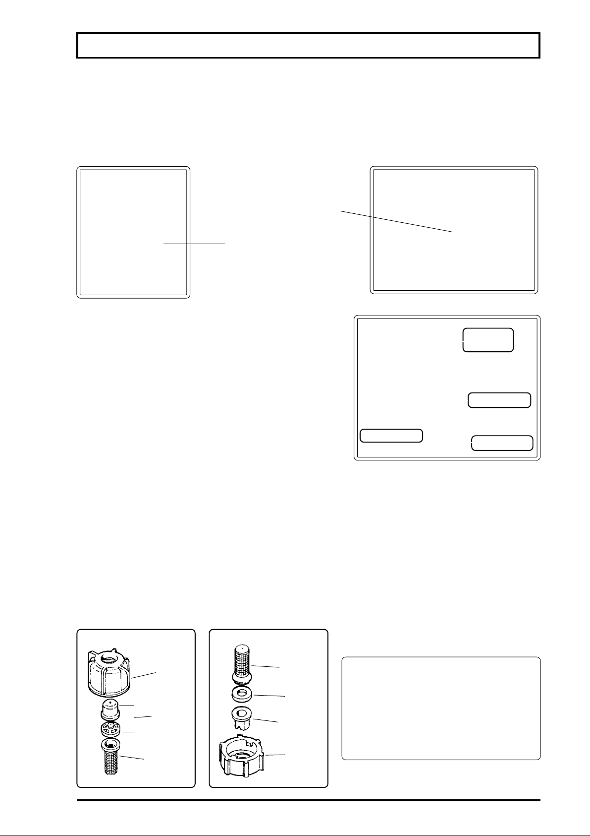
MOVEMENT SENSOR
The movement sensor is a device designed to replace the wheel sensor and its functions. It
provides the JSC-5000 with pulse signals that are coverted in information for better use of the
equipment and chemical application.
movement
sensor
sensor support
BIJET NONDRIP DOUBLE NOZZLE HOLDER
The Bijet nozzle holder comprises a nondrip valve and
flat fan
nozzle
two ceramic nozzles - 1 cone and 1 flat fan.
Its nondrip valve shuts off the chemical mixture flow
once the pressure comes down to 10 psi, thus preventing
nozzle holder
it from dripping.
nondrip valve
cone nozzle
NOZZLES
The job of the nozzles is to generate droplets and distribute them uniformly over the surface
being sprayed.
Flow, angle and droplet sizes vary according to working pressure. Operating with pressure over
that recommended by the manufacturer will decrease the nozzles' life.
This sprayer is equipped with alumina (ceramic) nozzles, which are very resistant to wear and to
chemical action, and fitted as shown in the figure below.
Cone nozzle
Flat fan nozzle
nozzle
cap
nozzle
filter
filter
seal
nozzle
nozzle
cap
21
ATTENTION:
Operating at pressures above or
below the recommended
can alter the nozzles
working characteristics.
Page 22
MAIN COMPONENTS OF SPRAYER
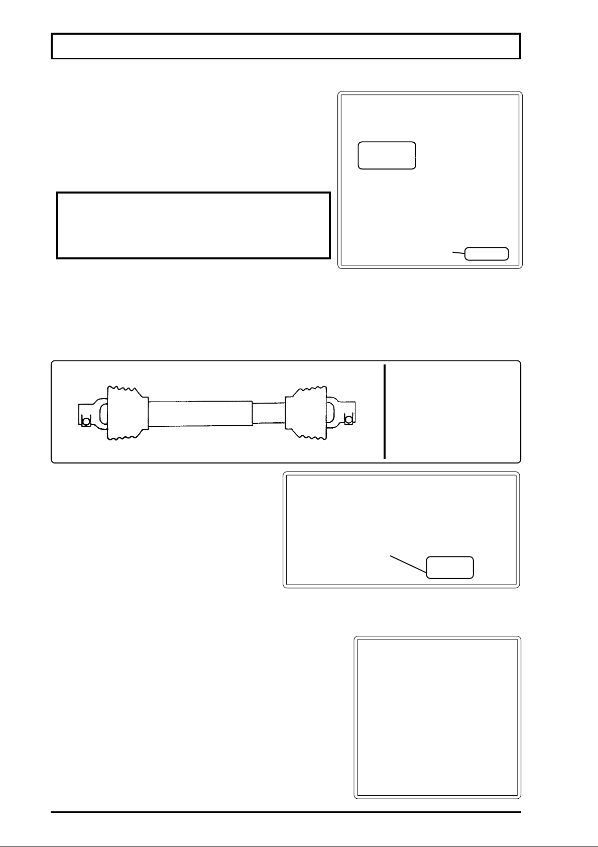
CLEAN WATER TANK
This is a plastic container with capacity of 3.17 gallons.
Easy to reach, it must always be filled up with clean water
for washing hands and other parts of the body that may have
touched chemicals while preparing the chemical mixture.
ATTENTION: USE THIS WATER ONLY TO WASH
HANDS AND OTHER PARTS OF THE BODY THAT
HAVE TOUCHED CHEMICALS. DO NOT DRINK
THIS WATER UNDER ANY CIRCUMSTANCES!
PTO SHAFT
It has plastic guards along all its parts to provide more safety to the operator. These guards
prevent the rotating parts from contacting the operator and his clothes, as well as plants. Do not
remove them.
clean water
tank
tap
NOTE:
For instructions in detail,
please refer to the section
MAINTENANCE - PTO
SHAFT.
BREAKAWAY SYSTEM
This system, mounted at the boom end, is
specifically designed to protect the boom
against impacts.
Upon shock against obstacles, the boom
end breaws away from its position, but returns
boom joint
to the normal operating position right after.
ATTENTION: This system will be able to protect the boom as long as such impacts must not
be strong and frequent.
IN-LINE FILTER
NOTE: As the FALCON VORTEX HORTI operates at
pressures above 150 psi, it is not equipped with this component.
It is possible to fit an in-line filter in each boom section.
This filter has 80 mesh and optimizes filtration to the nozzles.
TECHNICAL SPECIFICATIONS
Maximum working pressure ................... 150 psi
Filtering element mesh........................... 80
Hose fitting............................................. ø 1/2"
22
Page 23
MAIN COMPONENTS OF SPRAYER
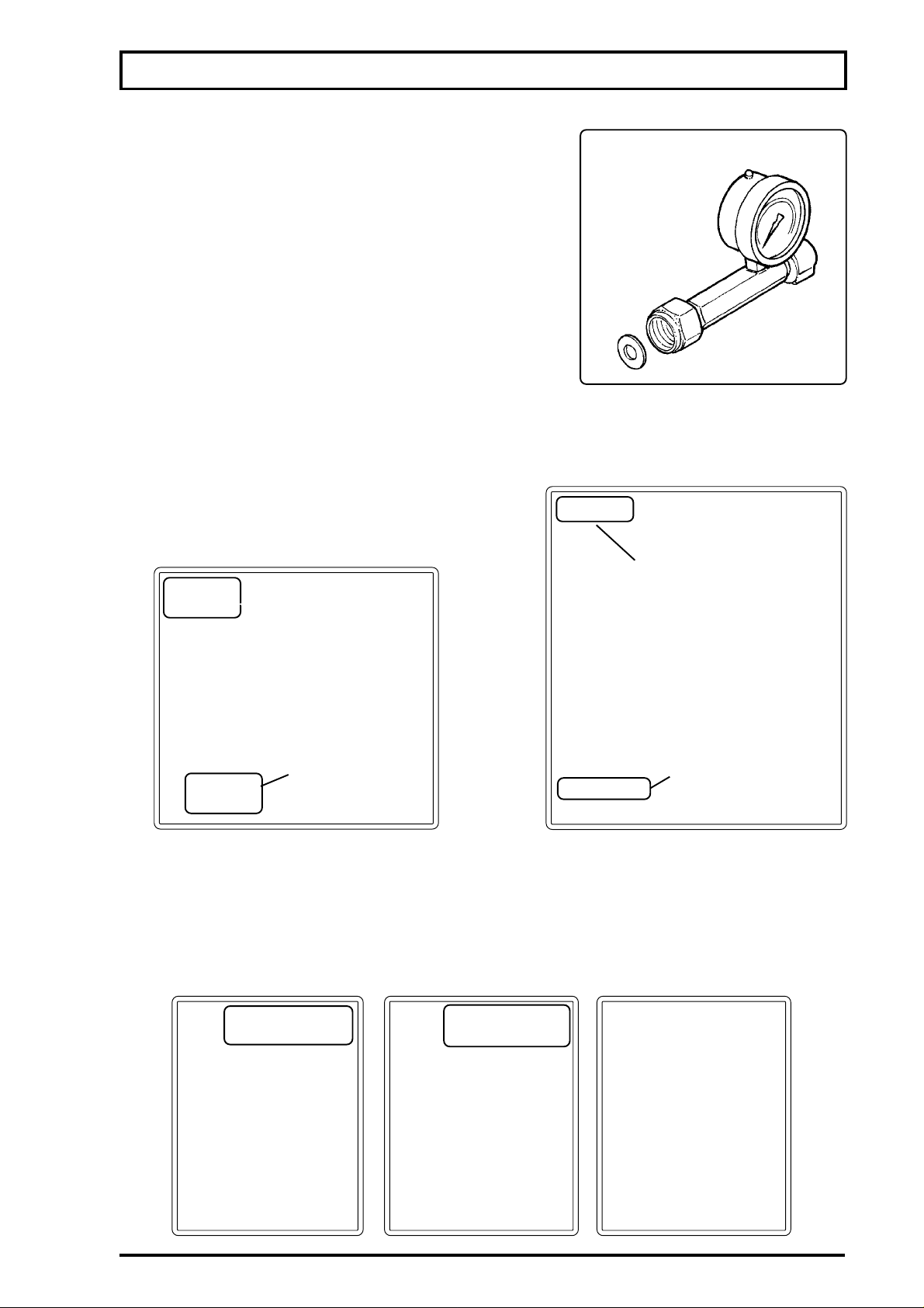
LOW PRESSURE GAUGE KIT (OPTIONAL)
The low pressure gauge kit was designed for
checking the actual pressure on nozzles.
It can be installed on the sprayers assembled with
both universal nozzle caps and fittings and complex
nozzle holders, such as double and quadruple units.
The maximum pressure of this kit is 100 psi.
However, the pressure regulators of sprayers can
easily reach above 100 psi, which can damage the
pressure gauge. To ensure longer life of the pressure
gauge, close the valve after regulating the sprayer.
FOAM MARKER (OPTIONAL)
LOW PRESSURE
GAUGE KIT
tank
ASSEMBLY PROCEDURES
control
panel
hydraulic
control
compressor
MOUNTING THE FOAM MARKER SUPPORT
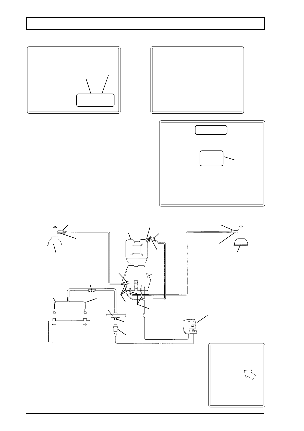
-The photographs below show how to mount the foam marker support to the sprayer chassis.
fastening point of
the support front
fastening point of
the support back
23
Page 24
MAIN COMPONENTS OF SPRAYER
MOUNTING THE FOAM NOZZLE
foam nozzle
support
MOUNTING THE CONTROL PANEL
- The control panel must be mounted on the hydraulic
control support, as shown in the photograph below.
control panel
hydraulic
control
DIAGRAM OF WIRING, AIR HOSE AND FOAMING AGENT HOSE
foam
nozzle
black
cable
blue hose
white hose
tractor
battery
fuse holder
red cable
tractor
panel
tank
white
hose
blue
hose
female
connector
male
connector
valve
White
hose
blue
hose
compressor
white
hose
ATTENTION:
After connecting the cables and hoses to the compressor base, tie
them up as shown in the photograph besides.
blue hose
white
hose
foam
nozzle
control
panel
NOTE: For more information on the use and maintenance of the
foam marker, consult the attached specific manual.
24
Page 25
MAIN COMPONENTS OF SPRAYER
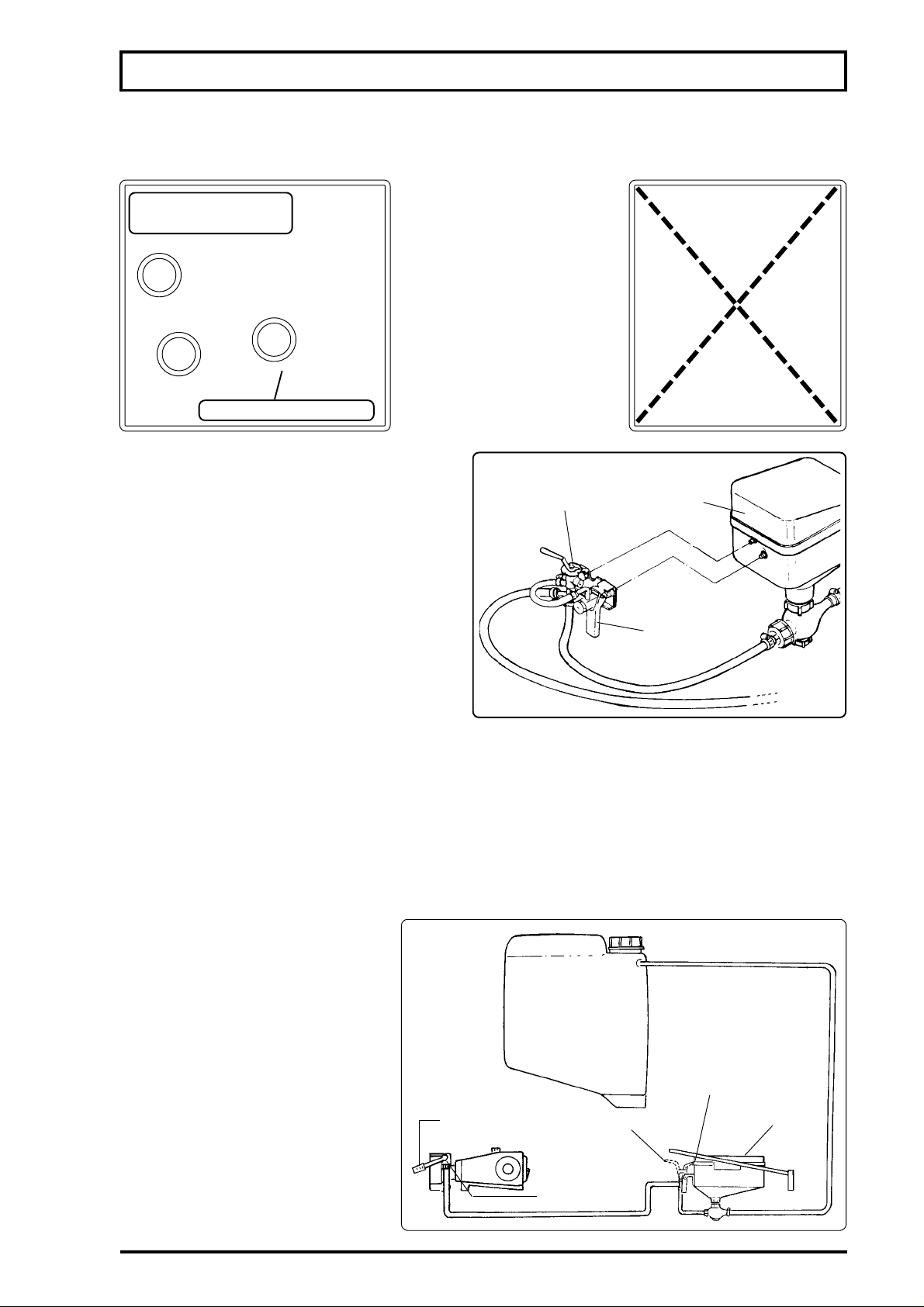
MOUNTING THE CHEMICALS MIXER GUARD RAIL
The chemicals mixer guard rail is shipped in the accessories box. It must be secured as shown
below.
fastening points of
the mixer guard rail
the chemicals mixer guard
rail as a platform to have
access to the tank filler
opening or to the foam
marker, as this can damage
the parts, as well as cause
the sprayer to turn over.
ATTENTION: Do not use
chemicals mixer guard rail
CHEMICALS MIXER
This component has a 3.96 gallons tank.
It is designed to avoid chemicals wastage,
provide fast filling operation and protect the
operator.
It can be used with liquids or wettable
powders.
flow bypass
valve
chemicals
mixer
container rinse
nozzle valve
MIXING CHEMICALS
-Turn the lever (1) down (on the sprayer column the decal indicates "Incorporador" ("Chemicals
Mixer").
-Pour the chemical or solution already prepared into the mixer tank.
-Engage the PTO.
-NOTE: The lever (2) can be positioned in two settings.
1- To mix chemicals.
2- To wash inside the mixer or to rinse the chemical container.
-With the lever (2) on the position
"Incorporação de defensivo"
("Mixing Chemicals"), all the
chemical will be transfered to the
sprayer tank.
-Rinse the chemical container;
afterwards, wash inside the mixer.
-After mixing the chemical, set the
lever (1) in the position "Válvulas
Superiores" ("upper valves").
filling position
(2)
flow bypass
valve
(lever (2))
chemicals
mixer
NOTE:
In case of liquids or wettable powders,
dilute the chemical in a pre-mixture
before filling the sprayer tank.
fill valve (1)
25
Page 26
MAIN COMPONENTS OF SPRAYER
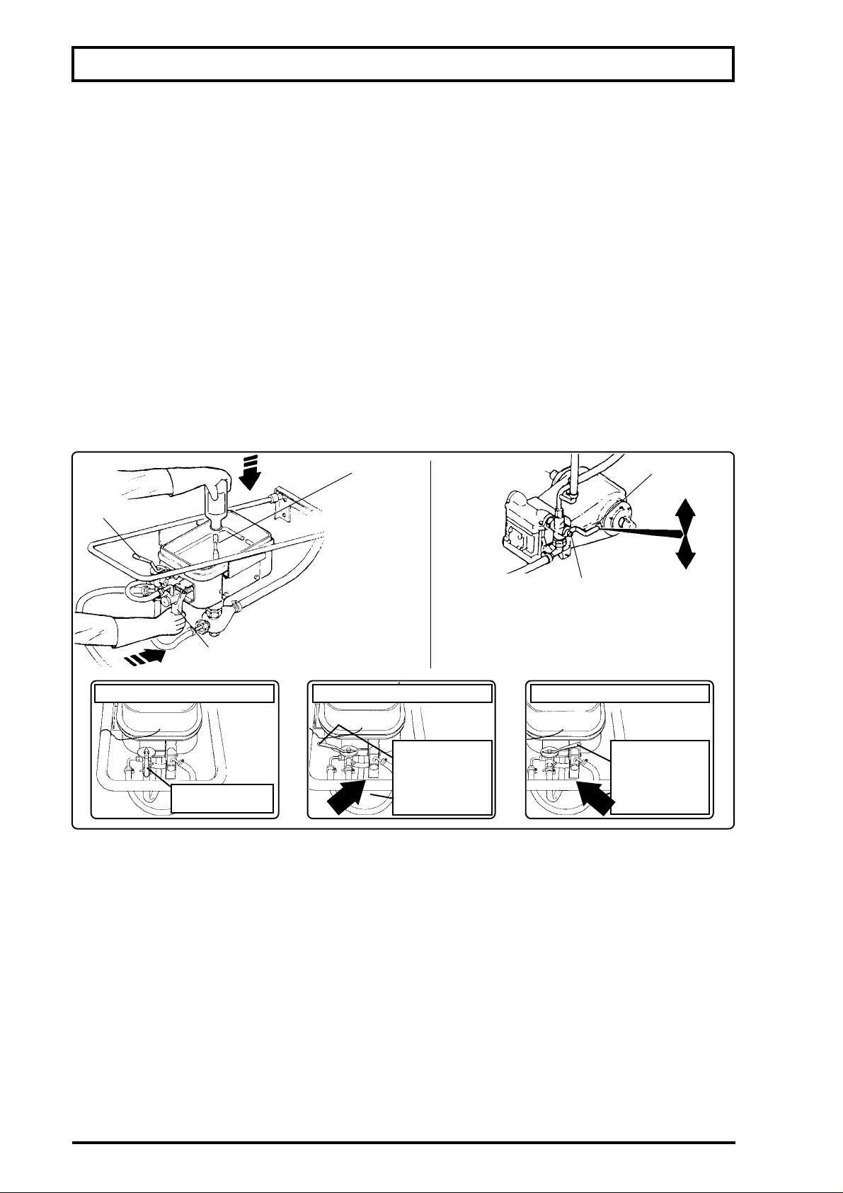
CHEMICAL CONTAINER RINSE NOZZLE
The chemical container rinse nozzle is mounted to chemicals mixer and is specifically designed
to remove all chemicals residues from the container after preparing the chemical mixture for a
secure disposal of such containers.
Some publications show that somewhere around 0.3% of the chemicals remains on the
container after being used. Therefore, discarding the containers without washing out the residues
is extremely dangerous to mankind, animals and enviroment.
Rinse the chemical containers right after using them, before the residues dry.
USE
- Set the lever (1) in the position "Incorporador" ("Chemicals Mixer") (detail of the decal affixed to
the sprayer column).
- The lever (2) must be set in the position for washing inside the mixer .
- Hold the chemical container over the rinse nozzle.
- Engage the PTO.
- Set the lever (3) in the position to rinse the container. Simultaneously, move the container in such
a way to rinse it completely.
- Repeat this operation several times.
- After rinsing the chemical container, set the lever (1) back to the position "Válvulas Superiores"
("Upper Valves").
nº 2
nº 3
Setting of lever (2)
Mixing chemical
container rinse
nozzle
ATTENTION
-Never operate the lever (3)
without a container over the
container rinse nozzle.
Setting of lever (2) Setting of lever (2)
Washing the
mixer / Rinsing
the chemical
FILLING VALVE
- With the lever pointing up, the chemical mixture
flow is directed to the nozzles.
- With the lever pointing down, the chemical mixture
flow is directed to the chemical mixer.
container
nº 1
Washing the
mixer / Rinsing
the chemical
container
ATTENTION
-
Each container should be rinsed at least twice to ensure the residues are completely
removed.
Watch out for sprinkling while rinsing the containers.
-
- After rinsing properly the empty chemical containers, dispose of them in an appropriate
place.
- Never leave empty chemicals containers anywhere, that is, in places where any untrained
person has acess to.
- Prepare an appropriate place for storing empty chemicals containers where only trained
person has acess to until having determined the final destination for them.
- Do not reuse the chemicals containers for any other purpose, whatever it may be.
- Always follow the technical recommendations and use the appropriate individual
protective clothing when handling chemicals.
26
Page 27
MAIN COMPONENTS OF SPRAYER
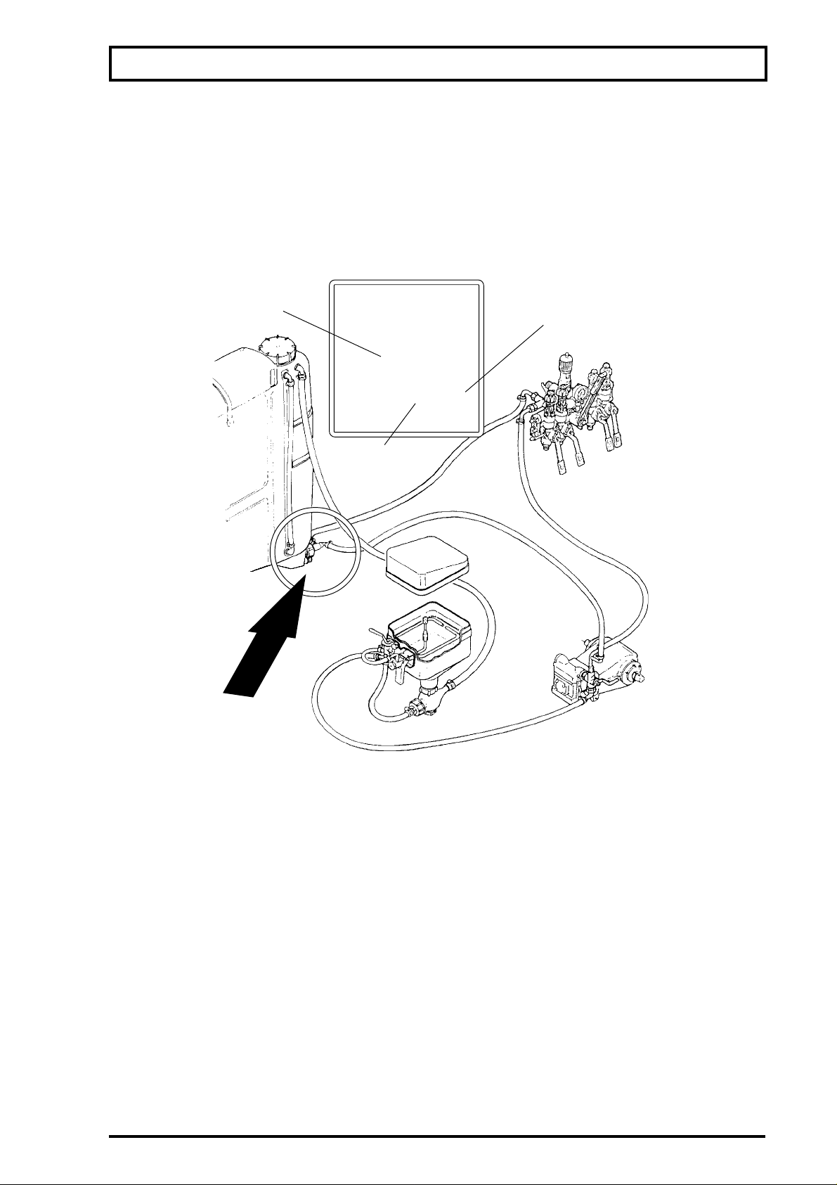
FLOW BYPASS VALVE
- It bypasses the chemical mixture flow to the nozzles or to the hydraulic agitator.
-After filling the tank and mixing the chemical, engage the PTO on the way from the filling spot to
the area to be sprayed.
-Set the lever of the flow bypass valve to the position "Descarga para o Tanque (agitação)
("Discharge to the Tank (agitation))". In this position, all the mixture will be agitated in the sprayer.
- In starting to spray, set this lever to the position "Comando de Pulverização" (" Spray Control"), in
which the main flow will be directed to the spray boom. The excess on the nozzles will return normally
through the circuit.
flow bypass
valve
spray
control
discharge to the
tank
(agitation)
HYDRAULIC AGITATOR
The agitator operation is the same of most of hydraulic agitators, in which a water flow passes
through throttling that increases its speed, and it, because of the "venturi principle" in the suction
chamber, draws a great deal of water at a speed lower than the entry speed.
The difference in comparison with other agitators is that this one has two inlets. One for high flow
rate (1" hose) and other for low flow rate (1/2" hose). On the low flow rate inlet, that is always in the
same pressure of the nozzles, there is a ceramic tablet that provides the following flow rates for
agitating the mixture:
-At a pressure of 20 psi on the circuit, around 0.79 gpm of chemical mixture pass by the tablet, that
represents due to the venturi system the circulation of 15.85 gpm of chemical mixture in constant
agitation.
-At a pressure of 300 psi on the circuit, around 2.37 gpm of chemical mixture per minute pass by
the tablet, that represents due to the venturi system the circulation of 52.83 gpm of chemical mixutre
in constant agitation.
The two outlets in the system work in different situation:
- The low flow rate inlet allows a continuous agitation in any situation of operation.
- The high flow rate inlet was designed to give a better condition for agitating the chemical mixture
while it is prepared and also on the way from the filling spot to the area to be sprayed.
27
Page 28
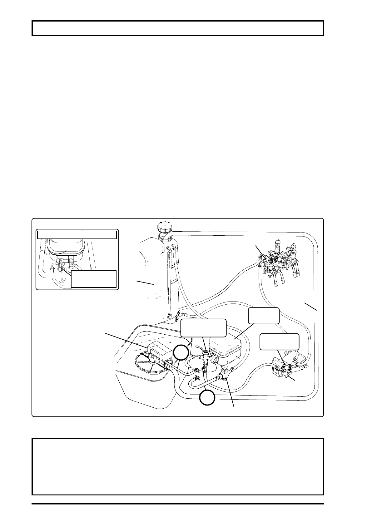
MAIN COMPONENTS OF SPRAYER
FILLER UNIT (OPTIONAL ACCESSORY)
-Put 13.20 gallons of water in the tank.
-Turn up the lever (1) (on the pump outlet valve). The decal affixed to the sprayer column indicates
"Válvulas Superiores" ("Upper Valves").
NOTE: The lever must be turned up in order to avoid the return of the chemical mixture existing in
this part of the circuit.
- Remove the hose "A" which connects the chemicals mixer valve with the chemical mixer base.
-Install the filler unit hose "B" in the place of the hose "A".
-Turn the lever (1) down (the decal affixed to the sprayer column indicates "Chemicals Mixer").
-Put the filler unit (3) in the water source and the end of its hose (4) in the tank opening.
-Engage the PTO (max. 540 rpm).
-The lever of the chemicals mixer valve (5) must be set to bypass the flow to the filler unit.
Attention: always be alert while filling the tank in order to avoid spillage of the chemical mixture onto
the ground.
- After finishing the filling operation, connect the hose "A" again to the chemicals mixer valve.
-Turn up again the lever (1) - "Válvulas Superiores" ("Upper Valves").
- Set the chemicals mixer lever (5) back to the working position.
setting of lever (5)
chemical
filling
filler unit
(3)
chemical control
(upper valves)
Tank
filling
hose (4)
chemicals
mixer
chemicals mixer
valve (5)
pump outlet
valve
"B"
(1)
"A"
chemicals mixer body base
PROTECT THE ENVIRONMENT.
IT IS EXTREMELY IMPORTANT FOR A HEALTHY LIFE.
ATTENTION
- THE SPRAYER FILLING OPERATION MUST BE DONE IN PLACES
APPROPRIATE FOR THIS PURPOSE OR THROUGH APPROPRIATE VEHICLES
(TRUCKS, TRAILERS, ETC.).
- NEVER COLLECT WATER FROM RIVERS, LAKES, DAMS, STREAMS, ETC.
BY USING THE SPRAYER´S RETURN SYSTEM.
28
Page 29

MAIN COMPONENTS OF SPRAYER
FAN ROTATION ADJUSTING VALVE
This valve adjusts the oil flow to run the hydraulic motor which actuates the fan.
The maximum fan rotation is 2,200 rpm.To change the rotation, just turn the knob:
clockwise to increase the rpm and counterclockwise to decrease the rpm.
Spraying grounds covered by vegetation (crops or strange plants) requires maximun
rpm, while for spraying clear grounds (no crop or vegetation) it is necessary to adjust the
rotation in order not to raise dust.
Another important factor is the power consumption: the lower the fan rpm, the lower the
power consumption (maximun power consumption with fan at 2,200 rpm=13 HP).
hydraulic motor lever
fan rotation
adjusting valve
SPRAY BOOM
This boom is specifically designed to make spray applications in windy days.
The air produced by the fan is uniformly distributed along the entire boom providing better
penetration of the chemicals with minimal drift level.
29
Page 30

OPERA TIONAL PROCEDURES
Stage
Spraying
Receiving the
sprayer
Using the sprayer
for the first time
Procedure
Use individual protective clothing.....................................
Do not work at high speeds.............................................
Do not spray against the wind .........................................
Do not travel with boom lifted or unlocked.......................
Take care with electricity supply cables ..........................
Do not eat, drink or smoke while spraying.......................
After spraying, dispose of all protective clothing and take a
shower ............................................................................
Check if all components are intact ..................................
Check the components of accessories box....................
Require trained person to instruct about assembling,
operating and servicing components and accessories ...
Check if the hitch pin is original .......................................
Check if the three-point hitch pins are original.................
Check if the hitch pins have cotter pins...........................
Check the overlaps of the PTO shaft ..............................
Remove the tractor's drawbar.........................................
Raise to the highest the tractor's hydraulic arms ............
Adjust the control valve position to avoid impacts while
turning .............................................................................
Check if the grease fittings are filled................................
Check if the oil is on the level on the components...........
Calibrate the tires ............................................................
Retighten the tank nuts and lug nuts ...............................
Sprayer type
Trailer
X
X
X
X
X
X
X
X
X
X
X
-
X
X
-
X
X
X
X
X
X
3 point
X
X
X
X
X
X
X
X
X
X
-
X
X
X
X
X
X
X
-
-
Whenever filling
the tank
Every day or
every 10 hours
First 30 hours
Every 100 hours
Every 500 hours
or annually
Clean the suction or line filters ........................................
Clean nozzles and their strainers....................................
Clean nozzles, strainers and filters .................................
Check the grease fittings and joint pins...........................
Check the oil level on the pumps and gear box ...............
Wash the inside and outside of the sprayer ....................
Check for damage on the paint and repaint.....................
Check for oil leakage and stop it......................................
Store the sprayer in a dry, ventilated and indoor place ....
Change for the first time the pump oil..............................
Retighten the bolts on the tank, axle and wheels..............
Change the oil of the pump and gearbox.........................
Tighten the belts ..............................................................
Clean and check the pressure regulator components ....
Clean the inside and outside of the sprayer, and paint the
parts subject to corrosion with lubricating oil...................
Service the pump ............................................................
Change hydraulic oil ........................................................
Change the oil of the gearbox..........................................
Retighten the bolts of tank, wheels, axle, etc. .................
Change the grease of the wheel hub...............................
X
X
X
X
X
X
X
X
X
X
X
X
X
X
X
X
X
X
X
X
X
X
X
X
X
X
X
X
X
X
X
X
X
X
X
X
-
-
30
Page 31
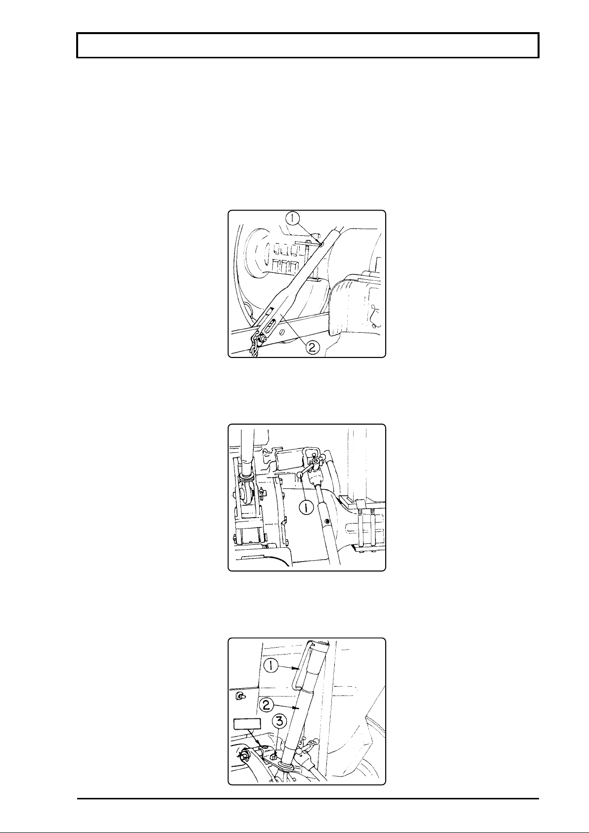
SETTING UP TRACTOR
ADJUSTING PARTS TO HITCH TO THE TRACTOR'S THREE-POINT SUSPENSION
ATTENTION: The instruction below is an example of what should be done for properly hitching
the sprayer to the tractor's three-point suspension. To exemplify we have used the Ford 4600
tractor. However, you should proceed as directed in the operator's manual of your tractor.
TIE ARM OF THE LEFT BAR
To adjust the length of the left lift arm to the proper position, loosen the pin and turn the lower half
(2) of the lift arm.
NOTE: The grease fitting (1) should point up.
LEVELLING BOX
To adjust the transversal levelling of the sprayer, turn the crank (1) located on the levelling
box.
ADJUSTING THE THIRD POINT
Release the lock (1) and turn the sleeve (2) to adjust the length of the third point arm. During
transport, fasten the plate of the third point bar to the pin (3) of the frame.
LOCK
31
Page 32
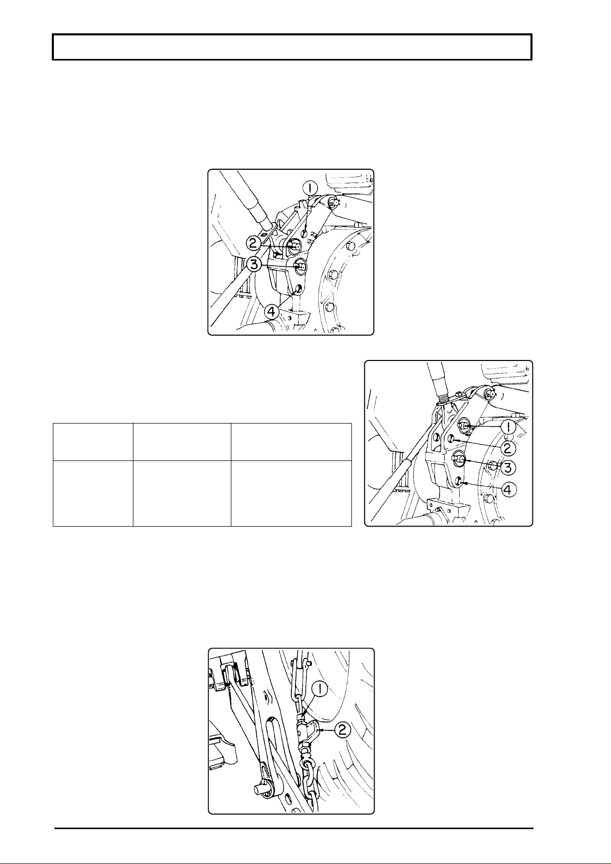
SETTING UP TRACTOR
ADJUSTING PARTS TO HITCH TO THE TRACTOR'S THREE-POINT SUSPENSION
THIRD POINT FRAME
The third point frame has two positions (1 and 2) to install the third arm and two positions
(3 and 4) to install the frame lower pin.
Thus there are four different positions for this assembly.
HOLES POSITION
The positions of the holes vary according to the duty to be
done.
Third arm's
position
No. 1
No. 1
No. 2
No. 2
STABILIZING CHAINS
The stabilizing chains should be installed to limit the lateral movement of the sprayer hitched
to the three-point system.
These chains should be adjusted according to the boom of the sprayer to be used. To adjust
them, relieve the lock nut (1) and turn the adjusting nut (2), as necessary, and retighten the lock
nut.
Frame
No. 4
No. 3
No. 4
No. 3
Duty kind
Ultra-light
Light
Medium
Heavy
32
Page 33
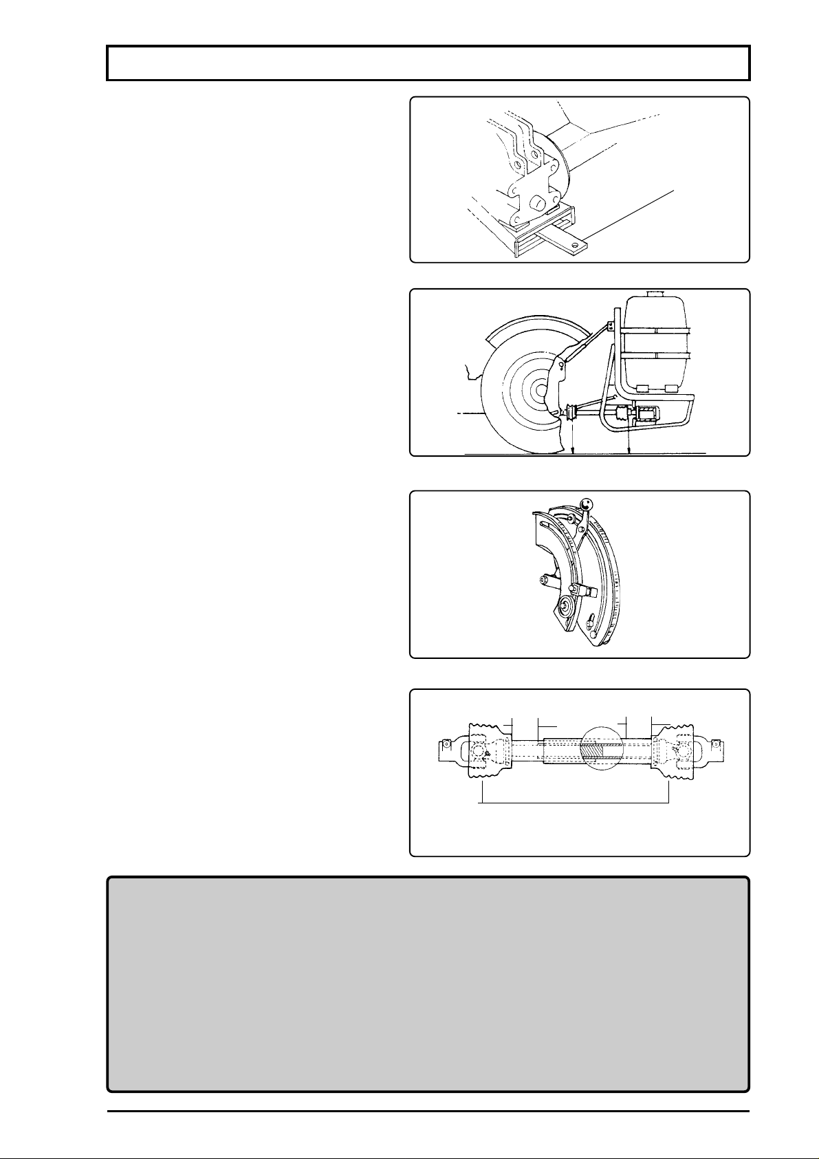
CONNECTING THE PTO
- Remove or set aside the tractor's drawbar.
- Mount the sprayer on the tractor's threepoint suspension and level it as shown in
the figure beside.
drawbar
h h
- Adjust the tractor hydraulic lift lever so
that the sprayer is not raised too high.
- Adjust the PTO shaft. If necessary, cut
the male and female tubes so that, after
connecting the sprayer, it has the overlaps
recommended in the figure beside.
height
adjustment
± 1.96 in ± 1.96 in
A
NOTE: Align the forks as shown by "A".
ATTENTION
- Mount all ballasts recommended by the tractor manufacturer before starting to
work with the Falcon Vortex sprayer.
- Before cutting the PTO shaft tubes, check for all possibilities of movement of
the sprayer on the lift arms and third point.
- Make sure the hitch pins locks are correctly installed.
- For instructions in detail, please refer to the section MAINTENANCE - PTO
SHAFT.
33
Page 34
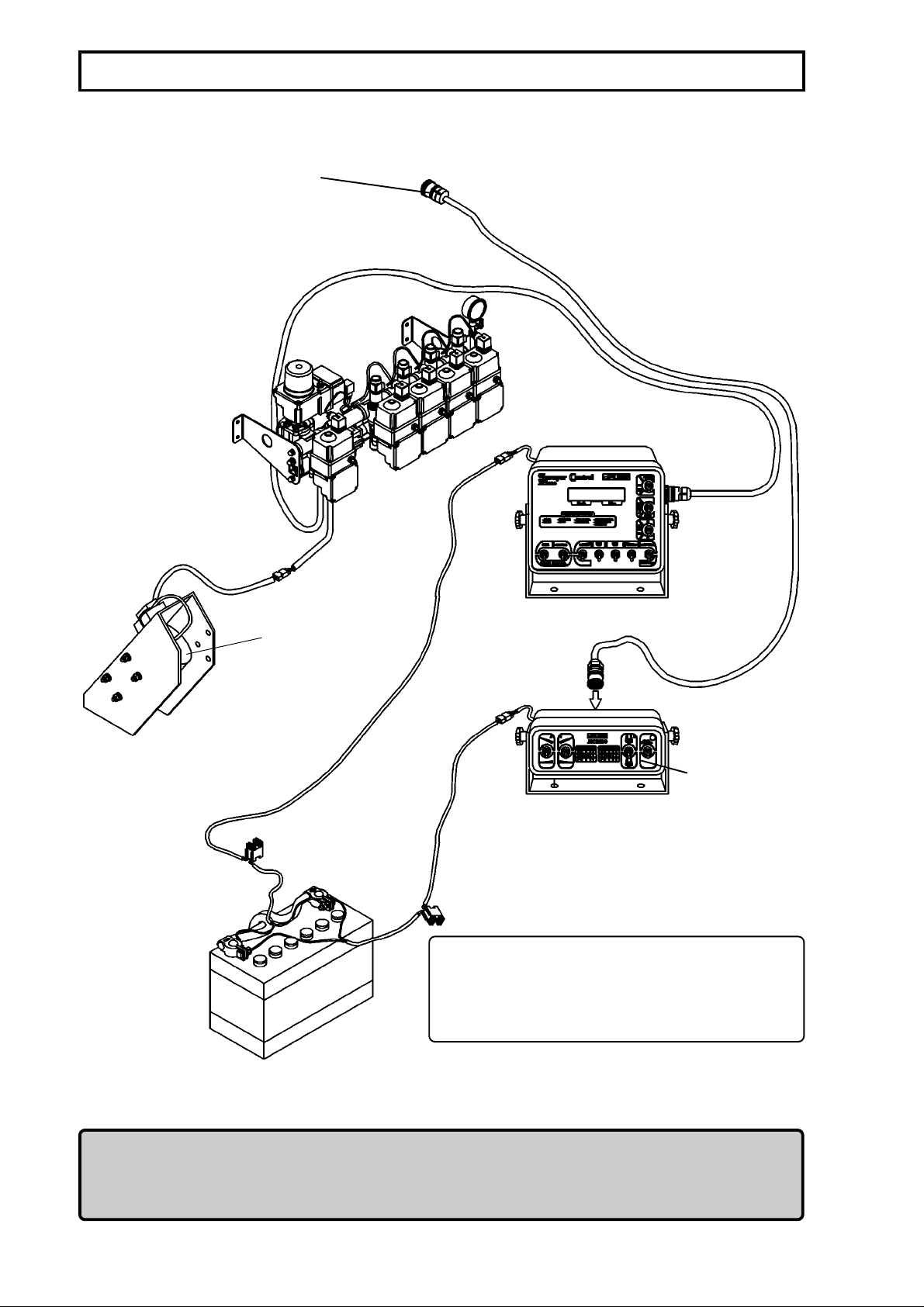
ASSEMBLING THE ELECTRO-ELECTRONIC CONTROL
hydraulic boom control
JSC-5000
black cable
(negative pole)
moviment
sensor
JEC-3600
red cable
(positive pole)
NOTE: The JEC, the panel and the JSC-5000
can be mounted in different places, together or
separated according to the operator's
convenience.
ATTENTION
- To handle batteries requires much attention since inside it there is acid liquid that causes injury to the skin
eyes, clothes, etc., besides being explosive.
- Take care to not connect the negative and positive poles invertedly. Otherwise, the battery can explode.
34
Page 35
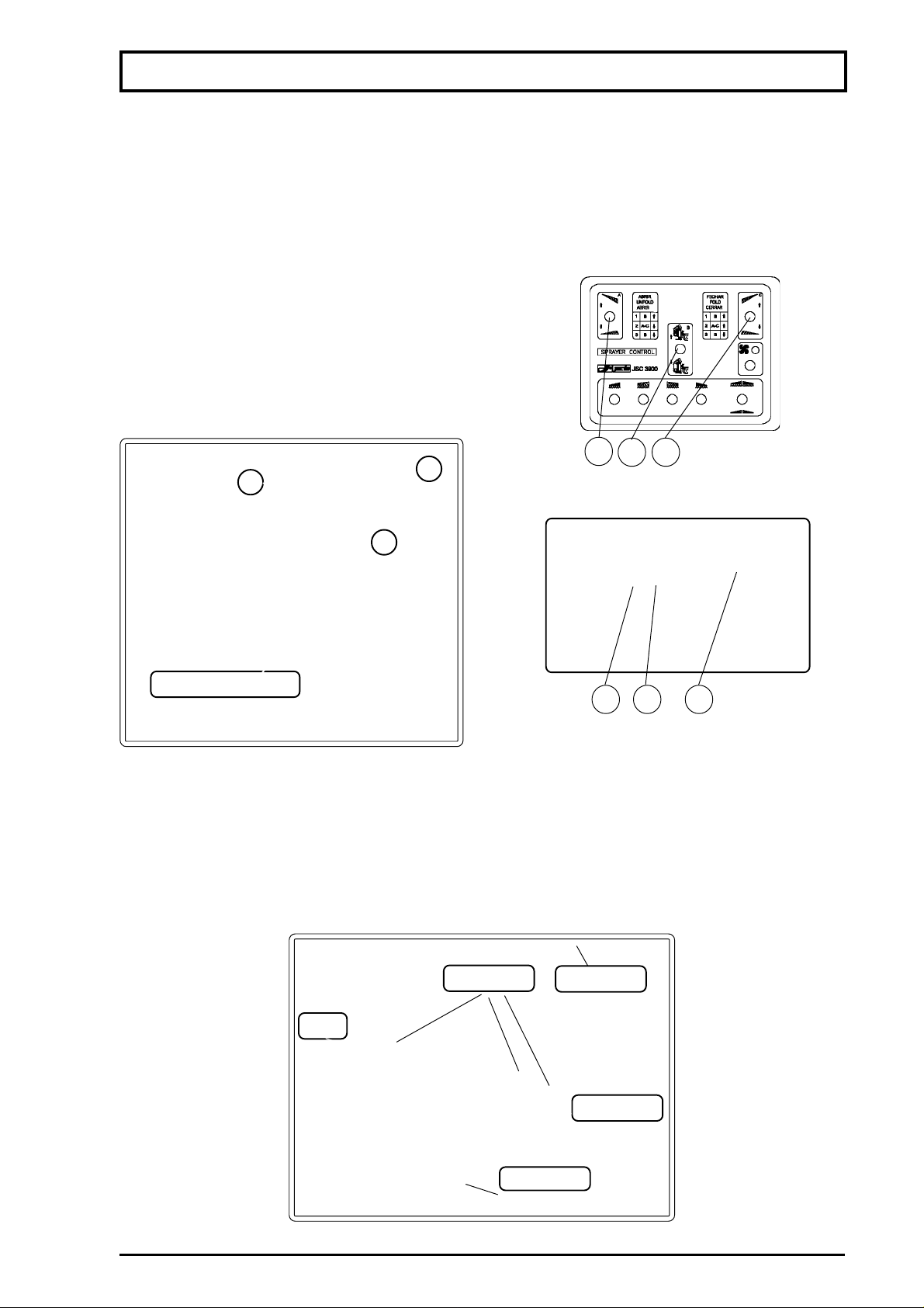
ASSEMBLING THE BOOM
ASSEMBLING, UNFOLDING AND FOLDING THE BOOM
ATTENTION:
- Before begining to assemble the boom and operate the hydraulic system, put clean water in the
tank to prevent the operation from damaging the chemical pump.
- Only unfold and fold the boom in areas free of obstacles such as trees, electricity supply cables,
etc.
ASSEMBLING THE BOOM
Hydraulic control
- Lever (1) -Operates the left boom.
- Lever (2) -Operates the frame.
- Lever (3) -Operates the right boom.
JEC 3900
JEC 3600
0203
01
hydraulic control
02
03
01
02 03
01
- Before assembling the boom, lower to the lowest the frame.
- Install the shaft, observing the orientation of assembling and the fitting of the flat washer with
the elastic pin.
- Do the same with both right and left boom.
ATTENTION: The cotter pin should be fitted in the side opposite the air duct mounting.
(1)
shaft
flat washer
spray boom
35
sliding frame
flexible pin
Page 36
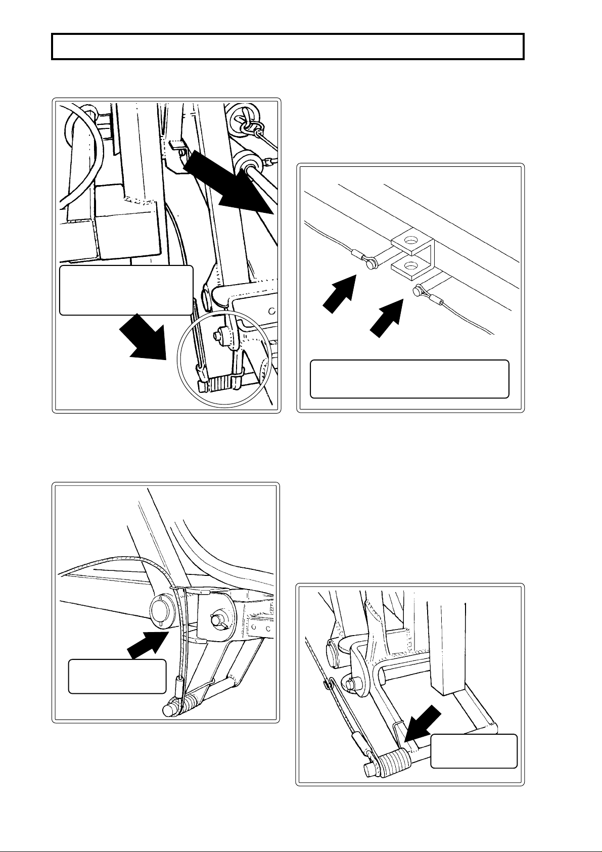
ASSEMBLING THE BOOM
ao attach the
oom
NCA
salizing cable on the
aizing
able
36
Page 37
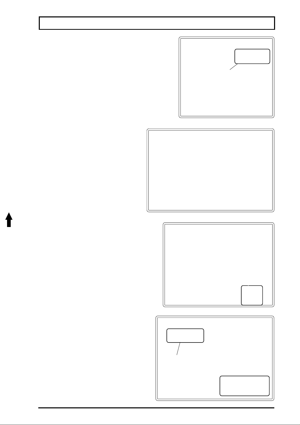
ASSEMBLING THE BOOM
-Mount the air duct protector to the boom.
air duct
protector
INSTALLING THE BOOM ACTUATION
CABLES
-Pass the steel cable through the spring
as shown in the photograph.
-Remove the spring fastening pin.
-Pass the pin through the ring on the end of the
steel cable, with the spring.
-Do the same on the other side of the boom and
fit the pin again.
spring
fastening
pin
ASSEMBLING THE BOOM CYLINDER
boom actuation
cylinder
-Move the lever 1 and 3 of the hydraulic
control until the cylinder rods are completely out
of the body as shown in the figure.
-Install the fastening pin in the boom.
-Repeat this operation to the other boom.
after fitting the pin,
install the flat washer
and the lock.
37
Page 38
THE BOOM
INSTALLING THE BOOM STEEL CABLE
-d the boom, as decribed in the section UNFOLDING AND FOLDING THE BO
framnhec
- Pul the boom endwth your hand
trying to raise it. This operaionwl release
the booocae
Ahe cable
-ning on the opng
caeo the boomhsng
exremty, as shown.
-sh
side of the boom.
Aocothe 2nd boomo
- Lower the sliding frame all the way onto fixed frame. The boo
ph bo
- Tofastenthe2s
n theloc
dt correcty in the supp loosen
thess
coely.
- Rgthethesa
m
Page 39
ASSEMBLING THE BOOM
INSTALLING THE HOSES
There are two hoses for each boom section.
Pass them through the space showed on the
drawing beside.
The hoses 1 and 2 have different lengths.
Hose (1) (shorter) must be connected to the
first line filter.
Hose (2) (longer) must be connected to the
second line filter.
Fasten the hoses with the clamps.
Do the same on the other boom section.
A
1
2
NOTE: For sprayers without line filter, the sequence for assembling is the same, that is, the shorter
hose is for the first boom section, and the longer one for the second boom section.
FASTENING THE MAIN AIR DUCT TO THE
BOOM AIR DUCT
The air ducts are fastened together by Velcro.
To fasten them correctly, just follow the seam
existing on the air duct.
MOUNTING THE AIR DUCT TO THE DEFLECTOR
-The air duct support (1) must be screwed on the air duct support, on the upper part of the frame
air duct
support (1)
The hose of the central boom (photograhph
below) must be connected to the beginning of
the branch on the first
boom section (detail A-).
air duct seam
air duct
rest (2)
39
Page 40

THE BOOM
-Aefixing the sut the can
sixation
to the rest
Page 41
UNFOLDING AND FOLDING THE BOOM
HYDRAULIC SYSTEM OPERATION, UNFOLDING/FOLDING THE BOOM
ATTENTION:
-Before starting to operate the hydraulic system
and to unfold and fold the boom, put clean water in
the tank to prevent from causing any damage to
the chemical pump.
- Only unfold and fold the boom in areas free of
obstacles such as trees, electricity supply cables,
etc.
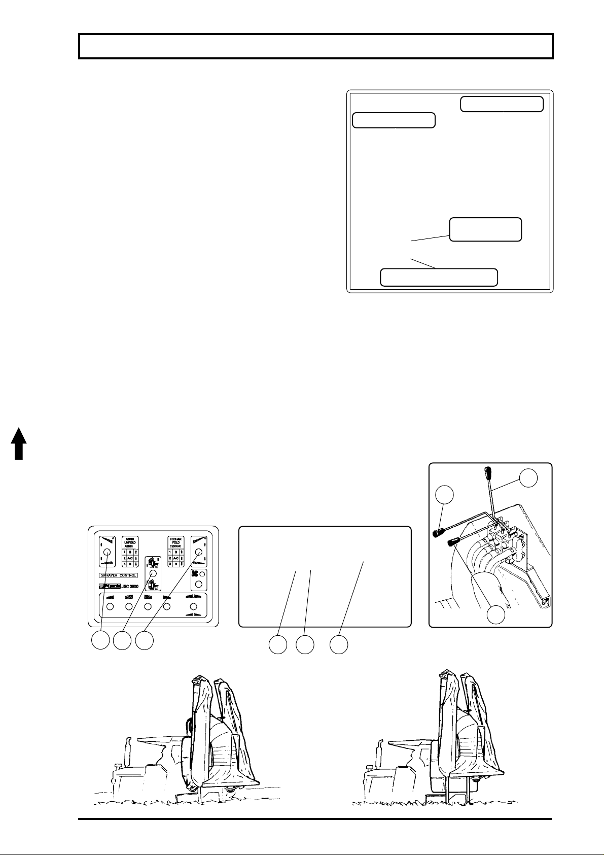
BOOM UNFOLDING AND FOLDING
The hydraulic control of your equipment can be actuated through JEC3600, JEC3900 or levers
according to your purchase order.
The controls must be mounted to the tractor fender on the most convenient position to the
operator. To install it, fasten a support on tractor fender and than the control.
The controls have 3 levers:
- Lever 01: raises and lower the right boom.
- Lever 02: raises and lower the frame.
- Lever 03: raises and lower the left boom.
To unfold and fold the booms, proceed as follows:
2311
- 1st: Operates the lever (2) until the frame is lifted all the way.
hydraulic control
chemical control
fan operation
lever
fan rotation adjusting valve
2
3
1
Lever hydraulic
JEC 3600JEC 3900
23
control
41
Page 42
NG NTHE BOOM
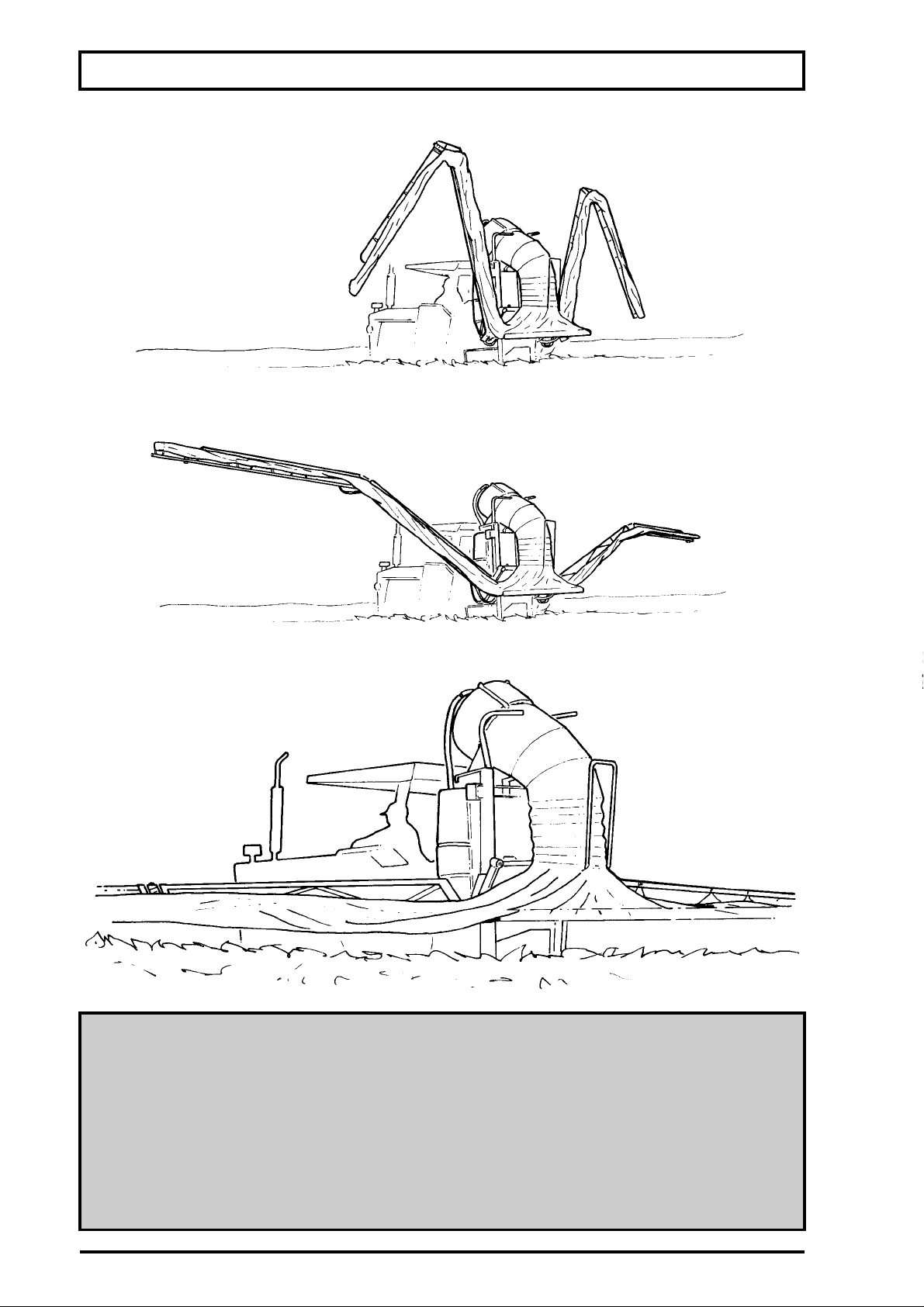
- 2nd Oae3 to unfold boo
- 3rd: Coinueto optheleves (1) and (3), by keeping the bootheb
a the way
- 4th: After unfolding the boom, lower the frame all the way and keepthe bo
othetarget.
ON
- Alwe
etc.
-T
slow
-A
-O
sec.
2
Page 43

OPERATION AND ADJUSTMENTS
SPRAY APPLICATION TECHNOLOGY
A successful spray application does not depend only on a good sprayer or correct use of the
chemicals but also on factors to be determined in the field under specialized orientation.
Among these factors, some concepts should be part of a criterion of evaluation so that positive
results may be attained within the pest control program.
-Ideal time- Application rate
-Safety-Good coverage
-Sprayer operational condition-Well trained operator
IDEAL TIME
The ideal time for spraying should be chosen according to the chemical product characteristics,
as well as to the field conditions:
-Infestation level of pests, diseases and weeds;
-Infection level of diseases;
-Growing stage of weeds;
-Weather conditions.
SAFETY
When spraying your crops, you must make sure there will be no risk to people, animals and
environment. Avoid spraying at hotter times, with humidity below 55% or under windy conditions.
Do not allow the operator to handle chemicals and spraying machinery without the proper
individual protective clothing.
CORRECT APPLICATION RATE
Any type of application requires that the rate be maintained during the whole spraying work. This
will be possible when you have a good sprayer properly calibrated.
This calibration can be obtained through practical methods or formulas. Please refer to the
section OPERATION AND ADJUSTMENTS - CALIBRATING THE SPRAYER.
GOOD COVERAGE
You have a good coverage when the whole target is sprayed with uniform distribution, with no risk
to the environment and with good results in the pest control.
The application rate does not have influence on the treatment results. Therefore good coverages
can be attained even with different rates, which may vary according to operational and regional
factors.
IMPORTANT!
READ CAREFULLY AND FOLLOW STRICTLY THE INSTRUCTIONS ON THE
CHEMICALS MANUFACTURER'S LABEL.
ALWAYS FOLLOW DIRECTIONS OF A TECHNICIAN WHEN HANDLING AND
APPLYING CHEMICALS.
ALWAYS MAKE SURE THE SPRAYER IS IN GOOD OPERATIONAL CONDITIONS
BEFORE STARTING THE SPRAYING JOB AND EMPLOY A WELL TRAINED
OPERATOR.
43
Page 44
ERAON S
MOCVALVE
cn relation to conveoncv
FLOWPTOTRAVEL
n a samheeaion is changethe volum
remns unchanged.
b
SAPRAOTWBO
SOIN USE
t has a systemh allows to calibrate the return of each boomsoa
peegthe nu
ON
n odto eeo the pre
hsthusreleasng the press anoshepe
THMASTEO
CABRANG THE WORNG PRESS
01-ea
02-entheoA
03-ThB
04-Thek
P)
4
Page 45
OPERATION AND ADJUSTMENTS
To calibrate every boom section, proceed as follows:
01-Run the sprayer and turn on the chemical flow to all boom sections.
02-Set the relief lever (1) in the position P [pressure].
03-Set the levers (2), (3), (4) and (5) to point down.
04-Check the pressure indicated by the pressure gauge.
05-Choose one of the boom sections and set the lever aside all the way [to turn off].
06-Other levers should remain pointing down [to turn on].
1
(P)
23
07-Check if the pressure indicated by the pressure gauge changed. If so, proceed as follows:
-Loosen the fastening screw shown by the arrow (figure E).
-Turn the knob clockwise to increase the operating pressure (figure F).
-Turn the knob counterclockwise to decrease the operating pressure (figure G).
NOTE:The pressure should be equal to that previously indicated by the pressure gauge when
the nozzles of this boom section were turned on.
-After calibrating the pressure gauge, set the lever back in the position "PULVERIZAR"
[SPRAY] (to point down/turn on).
-Do the same on every boom sections in order to maintain constant pressure along the entire
boom, regardless of the number of boom sections turned on.
EGF
ATTENTION:Do not change the rotation while checking the nozzles flow rate. Change on the
rotation will change the pressure on the nozzles and hence their flow rates.
D
54
45
Page 46
ERAON S
essure
ps)
06
0
07
5
08
0
10
0
11
20
13
50
14
80
10
15
40
16
70
19
00
YCERAC
JA
S
S
M
F
eJAlowcopo
o m
msh
bmAet is better coverage and more hom
Ta
coowo noe
T
poy for long time con reqe
coze
TA - FLOW RAE
5
1
g
8
0
4
5
7
8
145
0
2
3
NSTRANERS:nm
Page 47
OPERATION AND ADJUSTMENTS
Pressure
Nozzle
(psi)
Model
Color
60
90
JA - 1
Blue
150
210
60
90
JA - 1.5
Brown
150
210
60
90
JA - 2
Black
150
210
60
90
JA - 3
Orange
150
210
60
90
JA - 4
Red
150
210
60
90
JA - 5
Green
150
210
Ordering: Specify nozzle model and part #. Ex.: nozzle JA-2, part # 000026.
Blue
Color
Model
JA - 1
Part #
109744
Tractor speed (MPH)
Flow rate
2.5 3 4 4.5 5 5.5 6 6.5 7.5
(GPM)
Spraying volume (GPA)
3.42
3.74
4.06
4.60
5.13
6.84
8.22
10.26
0.08
5.87
4.06
4.38
4.91
5.45
6.09
8.12
9.72
12.18
0.10
6.94
5.34
5.87
6.41
7.16
8.00
10.68
12.82
16.03
0.13
9.19
5.87
6.41
7.05
7.80
8.87
11.75
14.10
17.63
0.14
9.94
4.60
5.02
5.55
6.09
6.95
9.20
11.00
13.78
0.11
7.90
6.09
7.37
8.33
5.55
6.62
0.14
11.11
13.35
16.67
9.51
7.05
7.70
8.44
0.17
9.40
10.58
14.10
16.88
21.16
12.07
8.22
8.97
9.83
11.00
12.40
16.45
19.77
24.68
0.20
14.10
6.84
7.48
8.22
0.17
9.08
10.26
13.68
16.45
20.52
11.75
8.12
8.87
9.72
0.20
10.80
12.18
16.24
19.45
24.36
13.90
10.68
11.65
12.82
14.21
16.03
21.37
25.65
32.06
0.26
18.27
12.07
13.14
14.53
16.13
18.16
24.15
28.96
36.23
0.30
20.73
9.40
10.26
11.32
12.50
14.10
18.81
22.55
28.21
0.23
16.13
11.32
12.40
13.57
15.06
17.00
22.65
27.14
34.00
0.28
19.45
14.32
15.60
17.20
19.13
21.48
28.64
34.41
42.96
0.35
24.58
18.27
22.33
25.22
16.77
20.09
50.33
0.41
33.55
40.30
28.75
13.35
14.53
16.03
0.33
17.84
20.09
26.71
32.06
40.07
22.87
16.13
17.63
19.34
21.48
24.26
32.27
38.68
48.41
0.40
27.68
30.67
20.41
22.23
24.47
0.50
27.25
40.82
48.95
61.23
34.95
23.72
25.86
28.42
0.59
31.63
35.58
47.45
56.96
71.17
40.72
17.10
18.70
20.52
22.76
25.65
34.20
41.04
51.30
0.42
29.28
20.62
22.55
24.80
27.46
31.00
41.25
49.50
61.88
0.51
35.37
26.07
28.42
31.31
34.73
39.11
52.15
62.62
78.23
0.64
44.67
30.45
33.23
36.55
40.61
45.74
60.91
73.10
91.37
0.75
52.26
Brown
Orange
Red
Green
Black
JA - 1,5
JA - 3
JA - 4
JA - 5
JA - 2
454256
454264
454272
000026
454280
47
Page 48
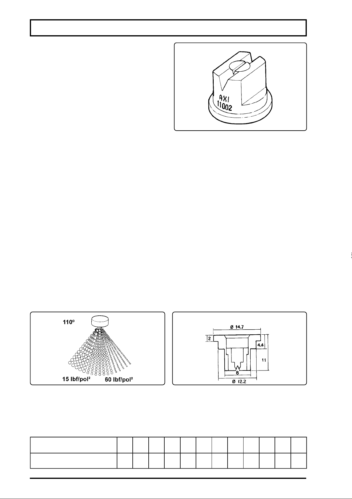
ERAON S
ES -10
FORM FLOW
C NOZZLES
Tow ceram
no precsion sprayng
To
-A 110.015G
2-A 110.02YELLOW
3-A 110.03BU
4-A 110.04RED
5-A 110.05BROW
Tat fan nozzles of Series AXI-110, maaumo
a 15p At lowe presdft is reduced by ge
aedopen
A highe press4 these noeod peoa
doets. (maxim
WRESISTANCE
To wAtests perform
U Uth
T Seies AX-11ae m
ealowufomy
ATTENTION:T
In orde to achieve spraying volumfromfeen
o the spraying volumnthe nep
0505
n (cm)
0
t
Page 49
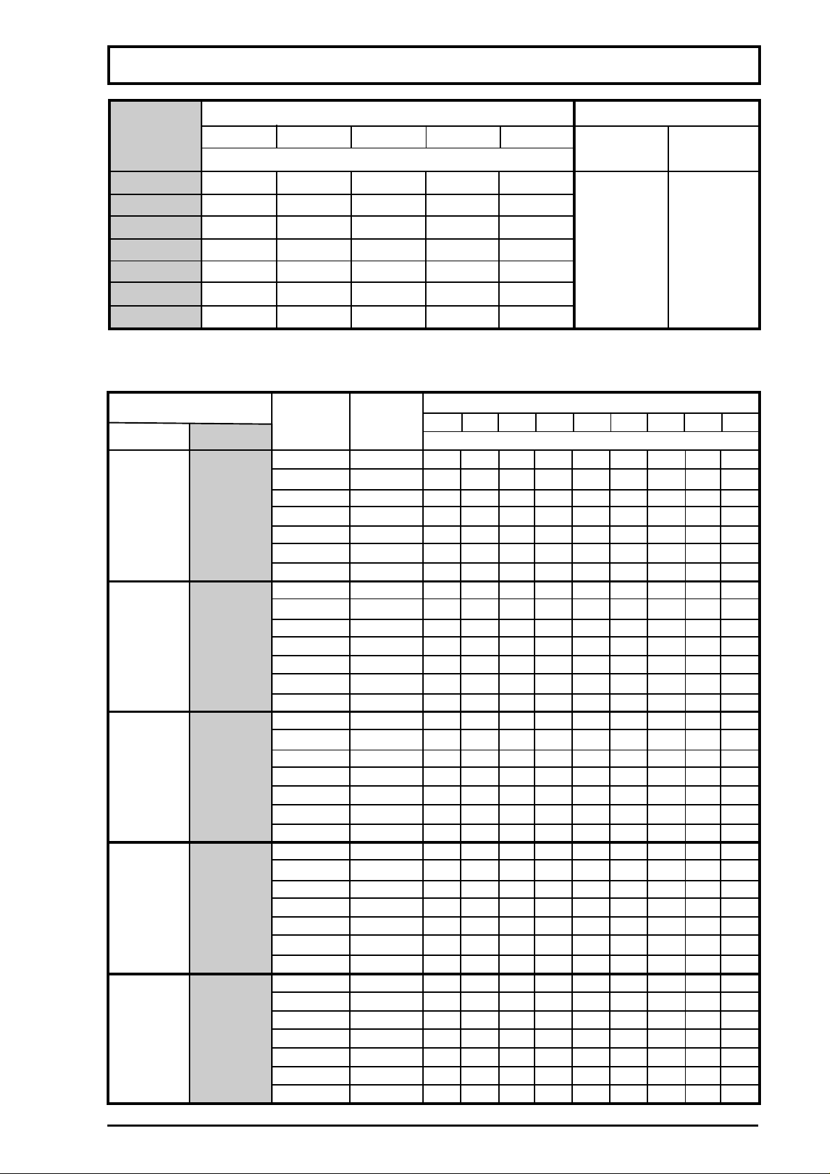
OPERATION AND ADJUSTMENTS
NOZZLES FLOW RATE (AXI -110) ORDERING
PRESSURE
YELLOW
GREEN
BLUERED
BROWN
NOZZLE
NOZZLE
(psi)
PART #
MODEL
Flow rate (gpm)
0.32
0.25
15
0.09
0.19
0.13
AXI 110.015
838862
0.38
0.29
0.21
0.15
20
0.10
AXI 110.02
838870
0.42
0.31
25
0.11
0.24
0.16
0.46
0.35
30
0.13
AXI 110.03
838888
0.26
0.18
0.49
0.38
35
0.14
0.27
0.19
AXI 110.04
838896
0.53
0.41
0.29
0.21
40
0.15
AXI 110.05
838904
0.56
0.43
0.31
0.22
45
0.16
SPRAYING VOLUME WITH NOZZLES SPACED AT 1.64 ft
TRACTOR SPEED (mph)
NOZZLE
PRESSURE
NOZZLE
2.503.004.004.505.005.506.507.509.00
FLOW RATE
(psi)
(gpm)
SPRAYING VOLUME (gpa)
MODELCOLOR
3.20
3.74
4.48
5.02
5.55
6.41
7.48
8.98
11.22
15
0.09
3.74
4.38
5.23
5.87
6.51
7.58
8.76
10.47
13.14
20
0.10
4.06
4.80
5.77
6.41
7.16
8.23
9.61
AXI
11.54
14.42
25
0.11
4.60
5.34
6.41
7.16
8.01
9.19
10.68
110.015
12.82
30
0.13
GREEN
16.03
4.80
5.66
6.84
7.58
8.44
9.72
11.32
13.57
17.00
35
0.14
5.23
6.09
7.26
8.12
9.08
10.47
12.18
(80 mesh)
14.64
40
0.15
18.27
5.45
6.41
7.69
8.55
9.61
11.00
45
0.16
12.82
15.39
19.23
4.70
5.45
6.51
7.26
8.12
9.30
10.90
15
13.03
16.35
0.13
5.34
6.19
7.48
8.22
9.29
10.58
12.40
14.85
18.60
0.15
5.87
20
6.84
8.22
9.08
10.26
11.75
13.68
AXI
16.45
0.16
25
20.52
6.41
7.48
8.97
9.93
110.02
11.22
12.82
14.96
YELLOW
17.95
22.44
0.18
6.84
30
8.01
9.61
10.68
11.97
13.68
15.81
19.23
0.19
35
24.04
7.26
8.55
10.26
11.43
(80 mesh)
12.82
14.64
0.21
17.10
40
20.52
25.65
7.70
8.97
10.80
11.97
13.46
15.39
0.22
17.95
45
21.58
26.93
6.62
7.69
9.19
10.26
11.54
13.14
15.39
18.49
23.08
0.19
15
7.48
8.76
10.47
11.64
13.14
14.96
0.21
17.52
20
21.05
26.29
8.33
9.72
11.64
12.93
AXI
14.53
16.67
19.45
25
23.30
29.27
0.24
9.19
10.68
12.82
14.21
110.03
16.03
18.27
21.37
30
BLUE
25.65
0.26
32.06
9.40
11.00
13.25
14.64
16.45
18.81
0.27
22.01
35
26.40
32.02
10.04
11.75
14.10
15.71
(50 mesh)
17.63
20.09
0.29
23.51
40
28.21
35.26
10.80
12.61
15.17
16.77
18.91
21.58
0.31
25.22
30.24
37.83
45
8.76
10.26
12.29
13.35
15.39
17.52
0.25
20.52
15
24.58
30.78
10.04
11.75
14.10
15.71
17.63
20.09
23.51
20
28.21
35.26
0.29
11.00
12.82
15.39
17.10
19.23
22.01
25.65
25
AXI
30.78
38.47
0.31
12.18
14.21
17.10
18.91
21.26
24.36
28.43
RED
110.04
34.09
0.35
30
42.64
13.14
15.39
18.48
20.52
23.08
26.39
0.38
30.78
35
36.98
46.17
14.21
16.56
19.87
22.12
(50 mesh)
24.79
28.42
0.41
33.13
40
39.75
49.70
14.96
17.42
20.94
23.19
26.07
29.81
0.43
34.84
45
41.78
52.26
11.22
13.14
15.81
17.52
19.66
22.55
26.29
15
31.52
39.44
0.32
13.25
15.50
18.59
20.62
23.19
26.50
31.00
20
37.19
46.49
0.38
14.64
AXI
17.10
20.52
22.76
25.65
29.28
34.20
41.04
0.42
25
110.05
51.30
16.03
18.70
22.44
24.90
28.00
32.06
0.46
37.40
30
44.88
56.10
17.20
BROWN
20.09
24.15
26.82
30.13
34.41
40.18
35
48.20
60.27
0.49
(50 mesh)
18.60
21.70
26.07
28.96
40
32.49
37.19
0.53
43.39
52.04
65.08
19.55
22.98
27.57
30.67
34.41
39.33
0.56
45.95
45
55.14
68.93
49
Page 50

ERAON S
BRATHSPRA
Ty of peoe anims ano
Twist below impa opeon proce
WNGCHEMCALS
- Folowctly the instructions onthea
- Us individual protective clothing recommend
- Don ea, drink or smoke
- Chated place
m
- W the bod
eve clothing recomm
toucheby ches.
sm
PROCEDURE
T
A
495
M
GPA =
S
H
5
Nt
Tactor speed 2.5 mph
Aconvu
495
495
GPA =
P=P
S
64
ON
T
Page 51
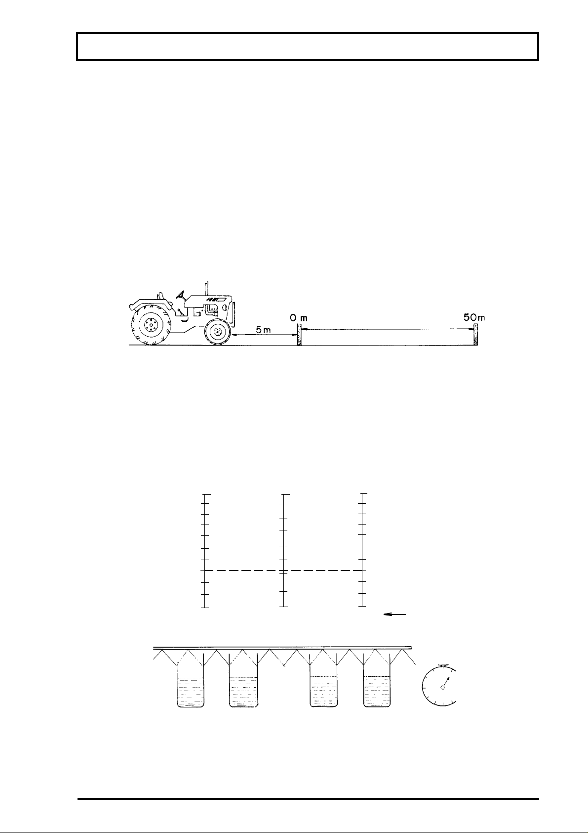
OPERATION AND ADJUSTMENTS
CALIBRATING THE SPRAYER WITH THE CALIBRATOR BOTTLE
BEFORE CALIBRATING THE SPRAYER BE SURE:
-suction filter is clean.
-hoses are not twisted or bored.
-pressure regulator components (valve seat, valve and spring) are not worn or dirty.
-pump is properly lubricated (oil level and grease) and has no leakage.
-nozzles are of the same model, not worn, with correct flow rate and with clean strainers.
AFTER CHECKING, PROCEED TO CALIBRATE AS FOLLOWS
1-Mark off 50 meters or 164.04 ft on the ground to be sprayer.
2-Fill up the sprayer.
3-Choose the working gear.
4-Engage the PTO.
5-Accelerate until reaching 540 rpm at the PTO.
6-Start moving at least 5 meters or 16.40 ft before the initial mark.
7-Note the time it takes the tractor to move 50 meters or 164.04 ft.
8-On irregular ground, repeat this operation several times and take the average.
9-Stop the tractor with the acceleration used to move the 50 meters, open the nozzles and adjust
the pressure according to directions for the different types of nozzles:
-Cone nozzles: from 45 to 200 psi
-Flat fan nozzles: from 15 to 60 psi
10-Use the calibrator bottle to collect the nozzle spray volume during the same time taken to move
the 50 meters or 164.04 ft, and read on the column corresponding to the nozzle spacing.
42.79 gpa0.26 gallon53.50 gpa
0.08 gallon12.83 gpa16.04 gpa
0 gallon00
Volume in gallon20 in
11-Repeat this operation with several nozzles to obtain an average volume.
12-The average obtained will be the spray volume for the gear and pressure already determined.
NOTE:1-If the spray volume obtained is below that wished, increase the pressure, decrease the
speed (but keep 540 rpm at PTO) or replace the nozzles by others of higher flow rate.
2-If the spray volume is above that wished, decrease the pressure, increase the speed
(but keep 540 rpm at PTO) or replace the nozzles by others of lower flow rate.
nozzle spacing
15.74 in
51
Page 52
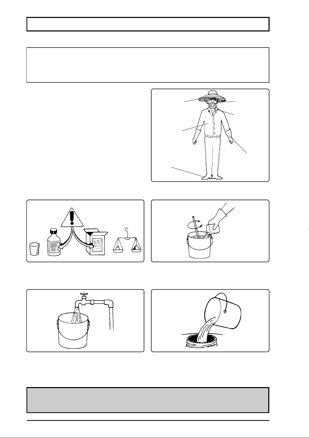
ERAON S
NGTHE CHEMCA
ON
the tank to avoid damthe pu
Awve
cothing whenhang che
m
-mwdbrimm
-es
-sk
-eothes
-mmgloves
-mmboots
XTU
ENTION
-y the chems m
label.e w
-Alling the bucke u
-Sr until the mixture is homogeneohaid and
ON
CRECOM
2
Page 53
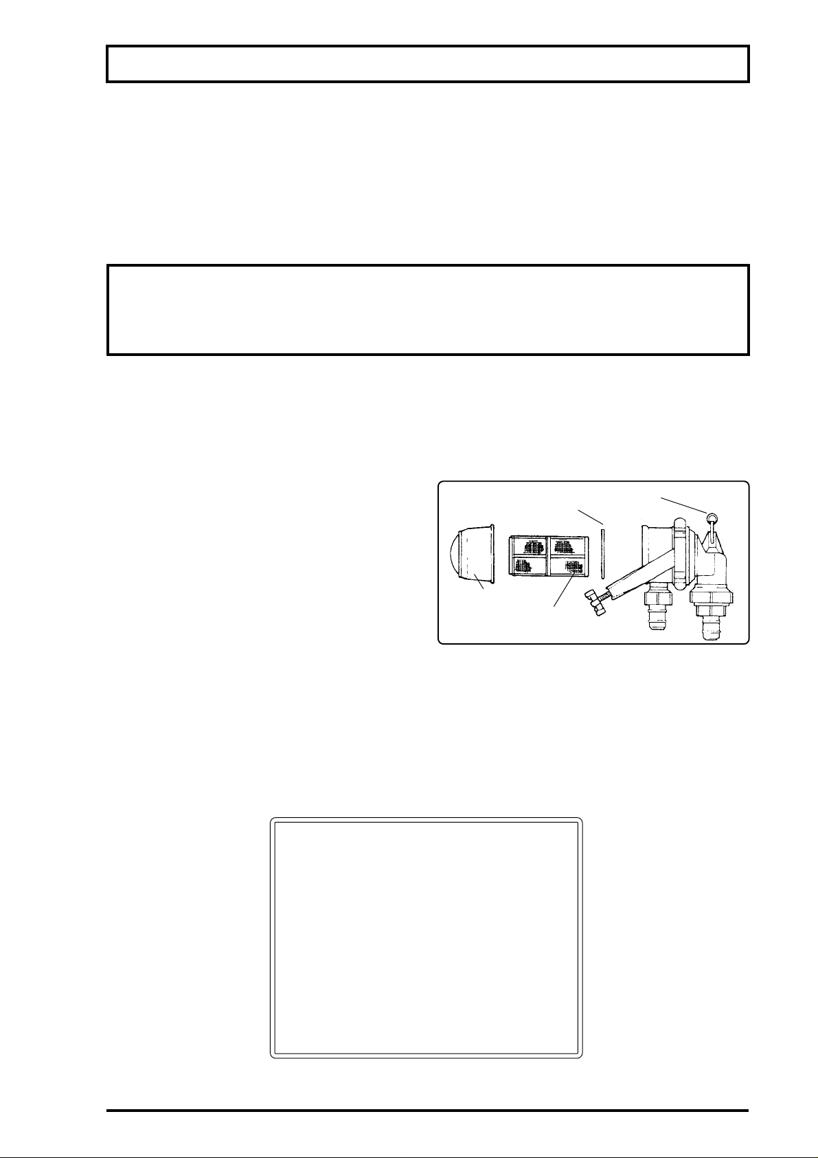
MAINTENANCE
GUIDELINES
-Daily, after finishing the spraying, put clean water on the tank, remove the nozzles and run the
sprayer till empty.
-Remove, clean and replace the nozzles and the filters.
-Clean the main filter.
-Wash the outside and inside of the sprayer.
These procedures will avoid problems with the sprayer in future application such as : obstruction
of the filters, nozzles, extensions and ducts, as well as protect your llife.
ATTENTION: NEVER WASH SPRAYERS OR PROTECTIVE CLOTHING
(MASK,GLOVES, WORKING CLOTHES, ETC.) IN OR CLOSE TO RIVERS, LAKES,
STREAMS, BROOKS, DAMS, ETC.
-Take off and wash all the individual protective equipment.
-Wash the working clothes separately from other clothes.
-Take a shower with plenty of water and soap and put clean clothes.
COMPONENTS MAINTENANCE
MAIN FILTER
-The frequency of filter cleaning depends on the
quality of water and type of chemicals used.
-Clean the filter when filling the tank or whenever
necessary.
IN-LINE FILTER (SPRAYER FALCON VORTEX)
-There is one in-line filter for each boom section.
-This filter has 80 mesh and optimizes the filtration to the nozzles.
- The frequency of filter cleaning depends on the quality of water and type of chemicals used.
-Clean the filter when filling the tank or whenever necessary.
valve
FVS 100
ring
filter cap
filtering
element
53
Page 54
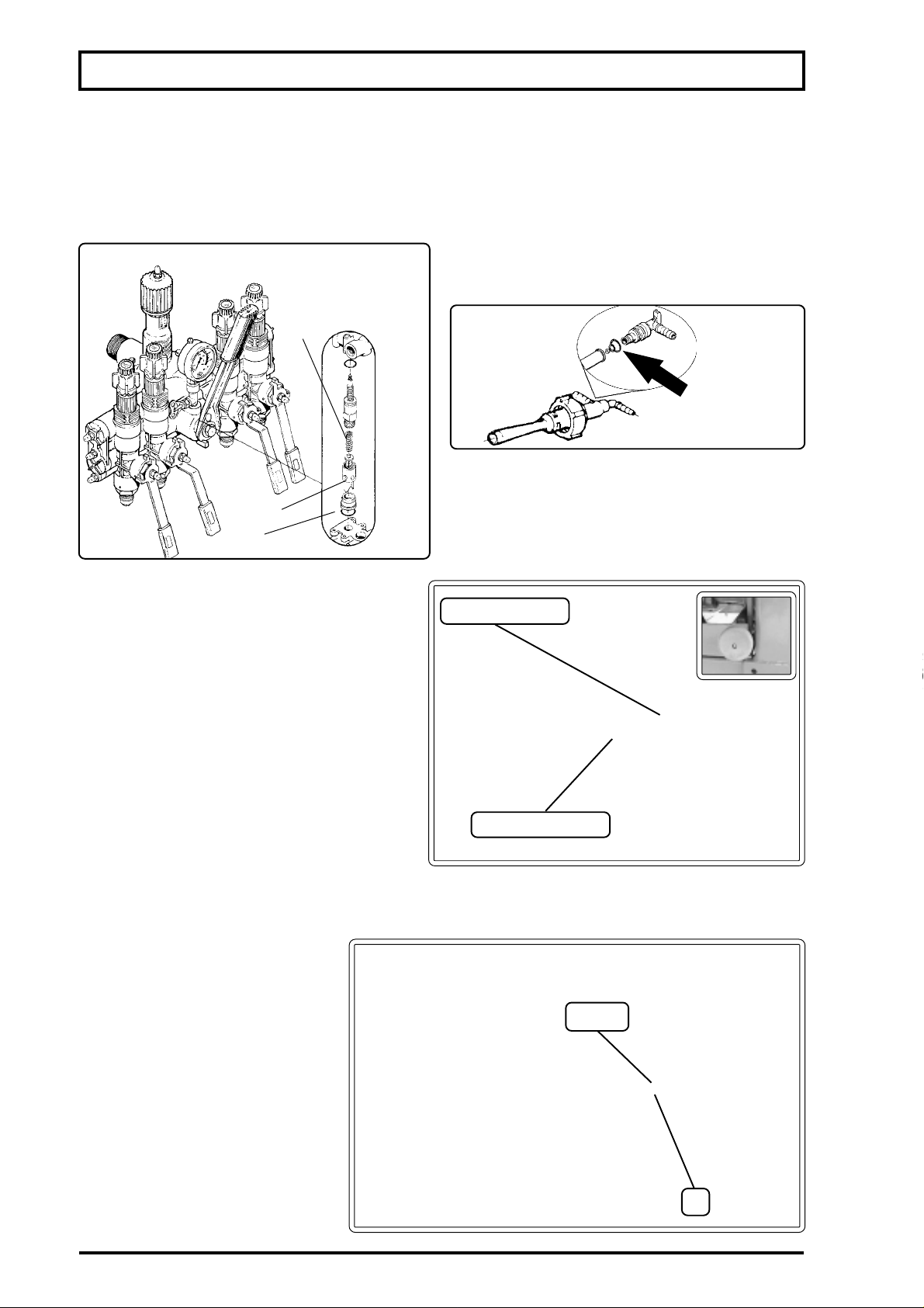
NTENANCE
PRESSURE REGULATOR
is recomm
-seo every100
wng hous.
-C
Rf necessay
RFLOW
OL
ng
ve
sea
HYPUBTENSION
pu
-the beng baN
side the pumonngthe tenson
reqefo the pefec opothe
system.
-Tgh the beang
base.
BOJOINT
-Tboothrough
the nu andlock nut. This adjustme
m the booms
m the
sa without even touching any
oo wt is very heavy
mficult the movement upon
ima obaes
wh
w
c
4
Page 55
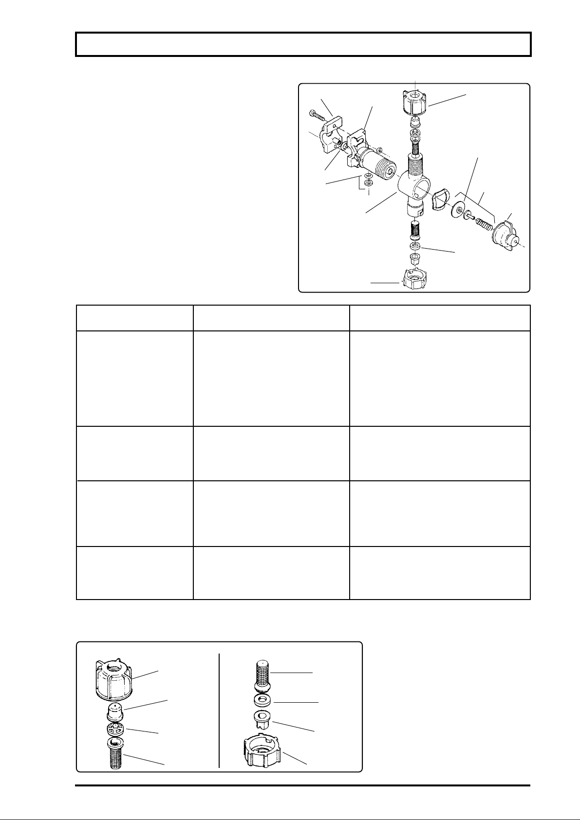
DOUBLE NOZZLE HOLDER
(MODEL BIJET)
After prolonged use, it may be necessary to
service the nondrip valve. Please refer to the
drawing beside and table below.
PROBLEMCORRECTIONCAUSE
Valve does not seal.
Leakage between
the nozzle holder
core and body.
Leakage through the
connection with
the spray tube.
Leakage through the
nozzle holder body
and the nozzle.
NOZZLES
- Clean the nozzles daily or whenever there is failure in the spray.
CONE NOZZLE
MAINTENANCE
5
4
core
diaphragm
3
piston
2
assembly
1
body
6
5
a - Tighten the nut (1).
a -Nut (1) not tightened properly.
b - Remove and clean the diaphragm.
b -Impurities on the diaphragm.
c - Replace the diaphragm.
c -Rupture of the diaphragm.
d - Replace the diaphragm and clean the
d-Rupture of the diaphragm
piston assembly
followed by chemicals buildup.
a -Seal (2) missing.
a - Fit the seal (2).
b -Seal (2) damaged.
b - Replace the seal (2).
c -Nut (1) not tightened properly.
c - Tighten the nut (1).
a -Fit the packing ring (3).
a -Packing ring (3) missing.
b -Replace the packing ring (3).
b - Packing ring (3) damaged.
c -Tighten the part (4).
c - Part (4) not tightened properly.
a - Nut (5) not tightened properly.
a -Tighten the nut (5).
b - Base of strainer (6) damaged.
b -Replace the strainer (6).
FLAT FAN NOZZLE ATTENTION
The flat fan nozzle (red) has is
nozzle cap
strainer
composed of a material subject
nozzle
seal
to crush to facilitate sealing.
Therefore the use of screw nozzle
swirl core
nozzle
cap is not recommended.
strainer
nozzle cap
55
Page 56
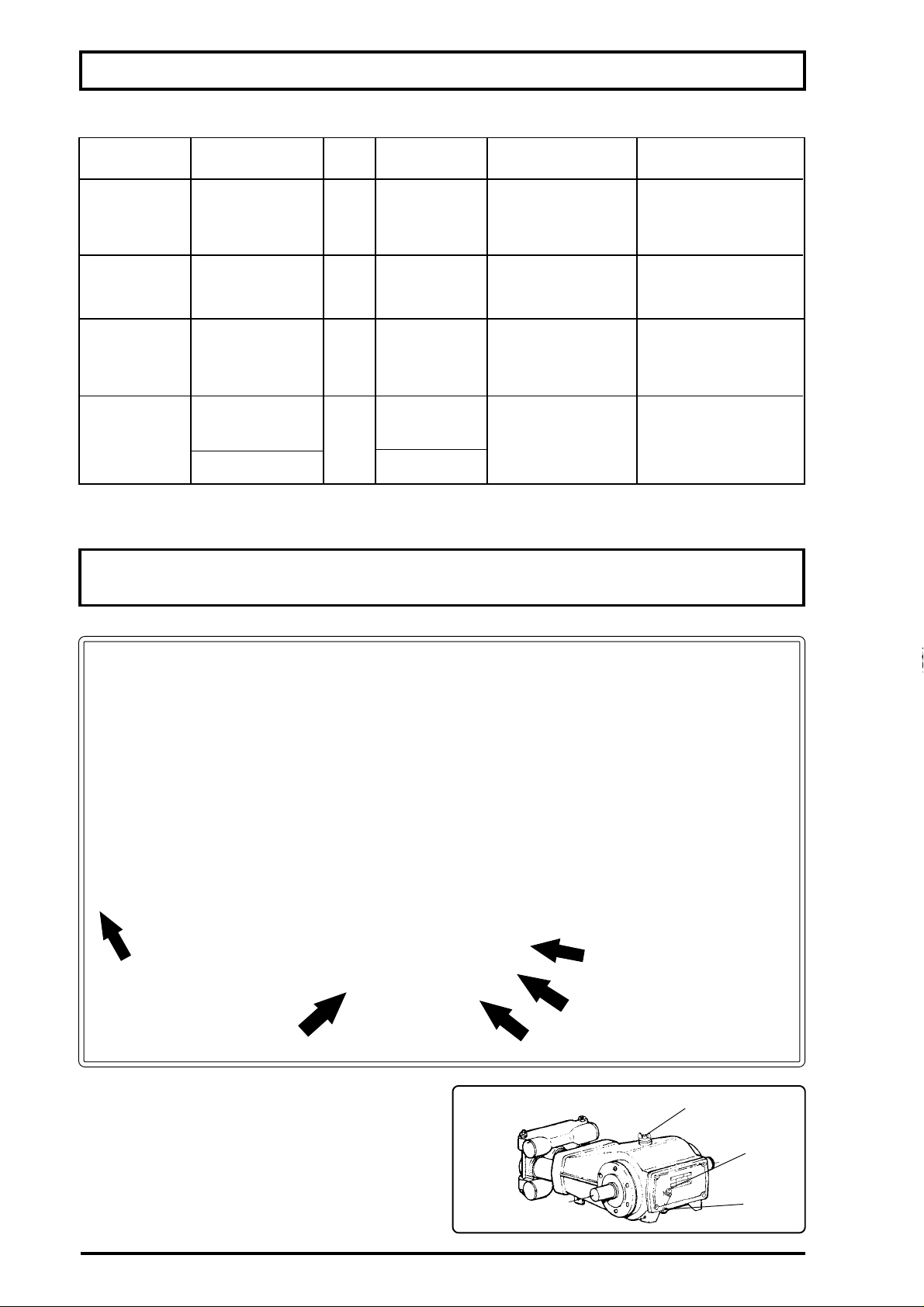
NTENANCE
CAT
YPRODUCTOENT
LUBRCATING
75 PUMP
L
HO
L
HOHYOIL
RESERVOR
FILTERING
ENGNE
LEMENT
HO
SHAFT
PPLES
NT
GREASE
DING FRAME
HO
DE
NO To recom
CANTS
AO ALWS
BNG
LUCANGOIL/GREASE
LUCANGOIL
CCAL PUMP
-C
-ll up if necessary.
- SA
Page 57
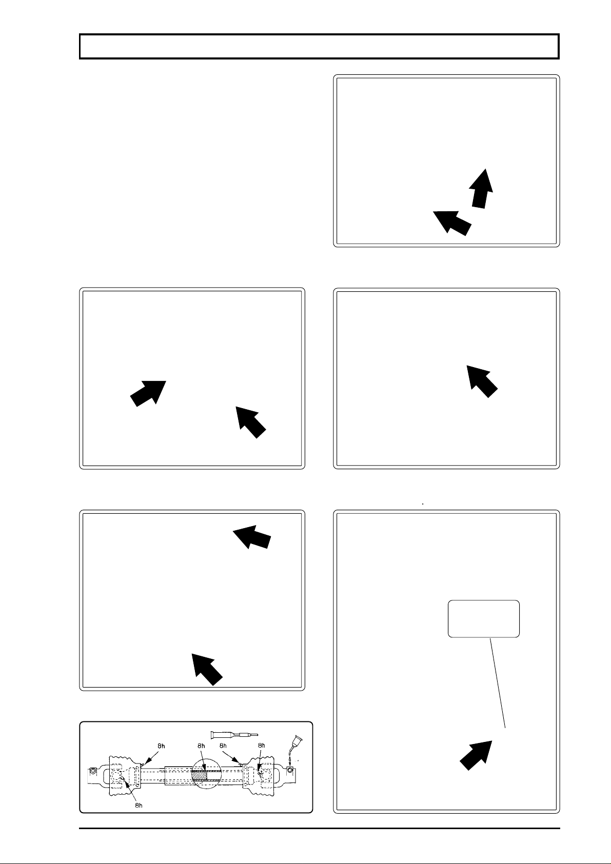
MAINTENANCE
LUBRICATING OIL
Lubricate with grease wherever there is a grease
nipple. Lubricate with lubricating oil wherever
there is a joint pin or shaft.
-Boom joint.
-Boom end breakaway .
-Sliding frame guide (it must be greased
regularly).
-PTO shaft.
sliding frame
guide
PTO SHAFT
Oil
57
Page 58

ller
ap
NTENANCE
HYOL RESERVOIR
mthat is more setive to impacs than the stee. Therefore, you shae
ws area
ain
Tre is the fan housing itself. The fan housing is maau
T
E
e
5
a
engeem
Page 59
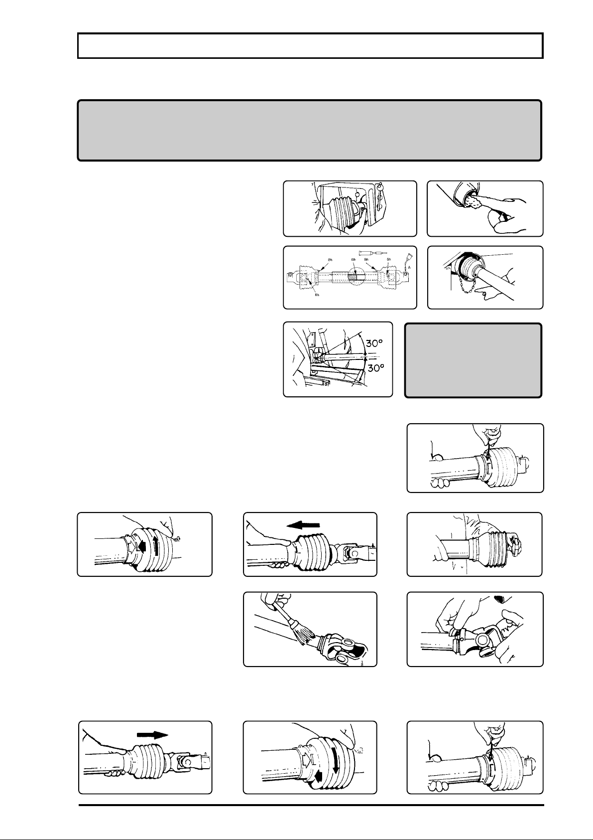
MAINTENANCE
CONVENTIONAL PTO SHAFT
WARNING: ONLY OPERATE WITH PTO SHAFT EQUIPPED WITH SAFETY GUARD. ALL
KIND OF MAINTENANCE ON THE PTO SHAFT MUST BE DONE WITH THE USE OF
APPROPRIATE PROTECTIVE CLOTHING, SUCH AS: GLOVES, BOOTS, GOGGLES,
ETC.
01- CONNECTING
-Check the PTO shaft length.
-Adjust the length by cutting the tubes
and protection guards proportionately.
Note:File and remove all burrs.
-Lubricate the male and female tubes.
-Connect the PTO shaft and install the
safety chain.
Note:Leave some slack on the
chain considering angular
movements.
-Disengage the PTO when making
sharp turns.
02- SERVICING
a) DISASSEMBLING
1- Remove the lock screw.
2- Turn the guard cone until the indicated position.
3- Pull the guard cone.
4- Remove the sliding ring.
b) ASSEMBLING
5-Clean and lubricate the male
and female tubes.
6-Install the sliding ring into the
fitting with the grooves pointing
toward the tube.
7-Install the protection guards.8-Turn the guard cone until the
indicated position.
ATTENTION
ONLY OPERATE WITH
PTO SHAFT EQUIPPED
WITH PROTECTION
GUARDS.
9-Install the lock screw.
59
Page 60
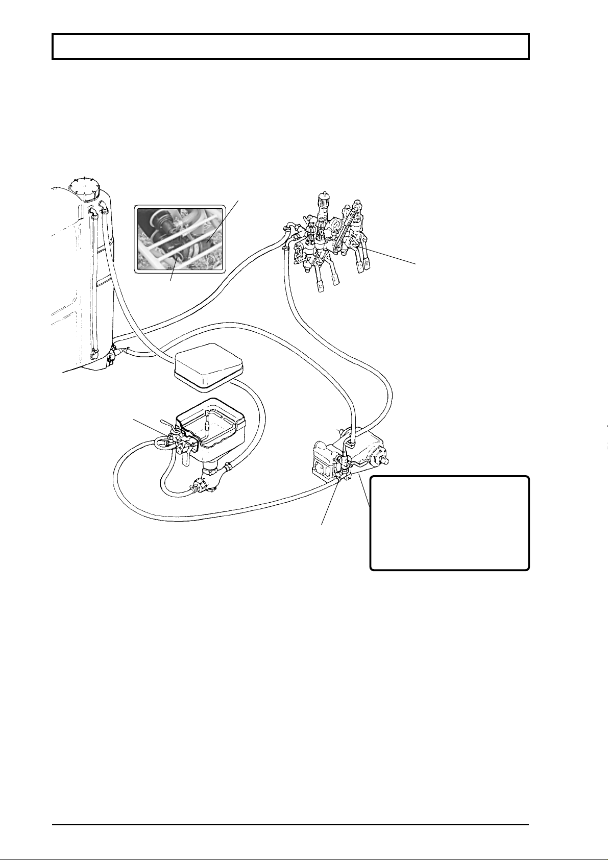
NTENANCE
STORAG
ATTENTION:n areas wthe wa
in the pump can freeze and cause serious dam
lter valve
-E
-Ringvve
-Rho ab3 spe
-Tling valve leve bah
-Rs opeon at the end of each wondm
future spray acaions
ter ca
as
xer
S
Nrecom
Page 61
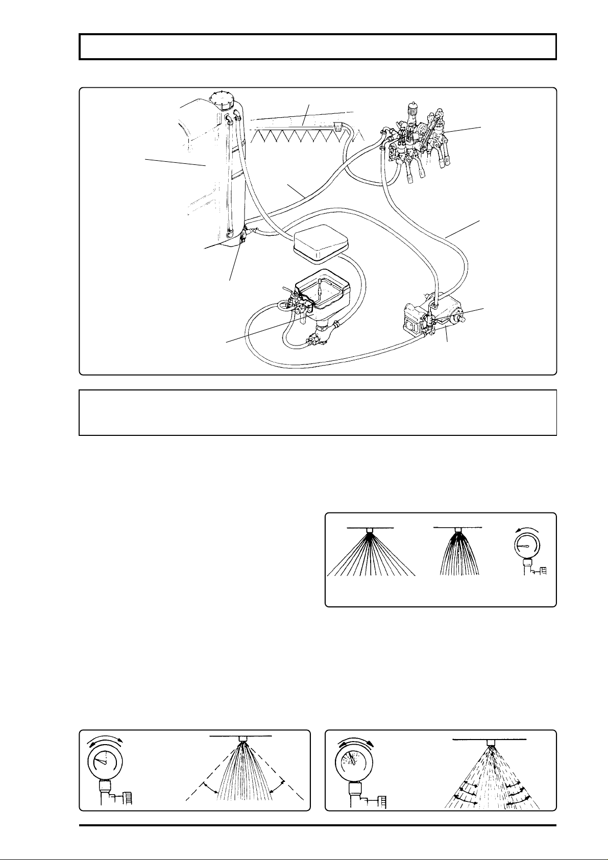
MAINTENANCE
TROUBLE-SHOOTING
tank
filter
chemicals
mixer
PROBLEMS - CAUSES - CORRECTIONS
Whenever Jacto sprayers equipped with piston pumps present problems, try to classify them
in one of the following four groups:
a) LACK OF SUCTION AND PUMPING CAPACITY
No liquid flow through the nozzles.
No return to the tank;
Pressure gauge does not indicate pressure.
b)PRESSURE DEFICIENCY
(PARTIAL LACK OF PRESSURE)
Desired pressure is not attained.
Specified nozzle spraying angle is not
attained.
Pressure gauge shows lower pressure.
c) PRESSURE OSCILLATION
The pressure gauge needle oscilates;
The nozzle spraying angle oscillates.
spray boom
chemical
control
return
hose
pressure
hose
filling valve
chemical
pump
deficient
normal
pressure
pressure
d) INTERMITTENT PRESSURE
The pressure gauge needle vibrates with
intensity.
The pressure hoses vibrate with intensity.
The nozzles spraying angle varies.
61
Page 62
CAUSES
CAUSES
NTENANCE
NG
a - LACK OF SUCTION AND PUMPING CAPATY
1-Punng.
sn
2-Lwnthe tank
3-lter shut off valve closed
4-Dlter.
wth mreq
5-On the intake hose
Fll up the tank whw
o
6-Ar in the system.
7-nsficient pumpson
b - PRESSURE DEFICIENCY
1-LowPTOrpm.
2-lter shut off valve closed
3-ter partially obstructed
4-ntakehy obsructed
e Fll the tank with water, openthev
flow
5-Ar in the system.
6-Peo.
whn the recom
7-Wes.
o
8-Powe
g
=109g
=18g
2
Page 63
c - PRESSURE OSCILLATION
2-Air in the intake system.
3-Pressure regulator.
d - INTERMITENT PRESSURE
PROBABLE CAUSESINDICATION AND CORRECTIONS
1-Valve closed
2-Pump valve deficiency
3-Pump head perforated internally.Replace it.
MAINTENANCE
SOLUTIONSPROBABLE CAUSES
Check belt tension and tighten if necessary.1-Loose belts.
Check for damaged hoses, filter packing rings, etc., and repair
if necessary.
Check the regulator components and clean or replace them if
necessary.
When the pump runs, liquid will pass through the valve even in closed
position, however flow will be insufficient.
Valve with sealing deficiency or stuck due to impurities.
63
Page 64

CARE
NG CULALSPRA
Wheowas that the UNREA
mamao
R an uns mh reco
chms
Foctly the instructions for proper use of this sprayer and chemicas to ens
saey andeficiency whesno
SPRANG
ATTENTION:
o che
- a propd
place.
-We
-
-lubricate andstore the sprayin a dry and co
-
-S to preve
-Thndvdu poeve clothing an
R
OO
S SPRAWTN
N
4
Page 65

STATEMENT OF LIMITED WARRANTY
MÁQUINAS AGRÍCOLAS JACTO S.A. warrants the equipment described herein and agrees to repair
or replace parts and components which, under normal operation and wear, following the technical
recommendations, show DEFECTS IN MATERIAL OR WORKMANSHIP.
WARRANTY PERIOD:
-One (1) year from the purchase date by the original retail purchaser.
WARRANTY APPLICATION:
Jacto or its authorized representative shall honor this warranty, if any part or component shows confirmed
defect in workmanship.
IT SHALL BE UNDERSTOOD THAT THE REPLACEMENT OF ASSEMBLIES SUCH AS PUMPS,
CONTROL VALVES, ENGINES, TRANSMISSIONS, HYDRAULIC PISTONS AND SIMILAR ONES SHALL
ONLY BE PERFORMED IN CASE THAT THE DEFECT CANNOT BE REPAIRED BY REPLACING
PARTS AND/OR COMPONENTS, NEW OR RECONDITIONED, ACCORDING TO RULES OR
AUTHORIZED REPRESENTATIVE.
THIS WARRANTY IS NULL AND VOID IF:
-Equipment is not used in accordance with the INSTRUCTION MANUAL, overwork or accidents.
-Improper preventive maintenance or performed by unauthorized people.
-Modification of the equipment in any way from the original design.
-Change, damage, or loss of the product identification plate.
-Utilization of parts and components not supplied by JACTO.
PRODUCT REGISTRATION CARD MUST BE COMPLETED BY THE ORIGINAL RETAIL
PURCHASER, AND RETURNED TO JACTO DEALER WITHIN 30 DAYS OF PURCHASE DATE.
WARRANTY EXCLUSIONS:
-Parts considered as normal maintenance such as: filtering elements, belts, hoses, nozzles, pistons,
pressure gauges, as well as usual maintenance, adjustments, retightening, lubrication and painting.
-Parts which show wear or tear due to use, UNLESS THEY SHOW DEFECTS IN WORKMANSHIP,
ASSEMBLY OR MATERIAL.
-Hydraulic, lubricating oils and grease.
-Injuries of personal or material nature to the user, owner, or third parties.
-Additional charges resulting from paralyzation and repair of the equipment.
-Freight charges, pick up and delivery charges.
-Damages of any nature resulting from action of gases or liquids used in the equipment.
GENERAL INFORMATION:
-Defective parts replaced under warranty period shall be property of JACTO.
-Eventual delays in performing services do not confer the owner the right to indemnity or to extension
of the warranty period.
-JACTO reserves the right to change its products or to interrupt manufacturing the equipment.
-THIS LIMITED WARRANTY shall be understood by its expressed terms, and no one in anyway subject
to JACTO shall be authorized to modify or amplify the conditions prescribed herein.
-In case of warranty claim, contact the authorized dealer supplying all information required for prompt
service. Do not forget the identification of the equipment, total hours of work, and the noticed defect.
FOR THIS WARRANTY TO BECOME EFFECTIVE THE PRODUCT REGISTRATION CARD FOUND
IN THE INSTRUCTION MANUAL MUST BE FILLED IN AND RETURNED TO YOUR JACTO DEALER.
THIS CARD MUST BE SIGNED BY THE ORIGINAL RETAIL PURCHASER, INDICATING THAT HE HAS
READ AND UNDERSTOOD ALL SAFETY AND OPERATIONAL INSTRUCTIONS IN THE MANUAL,
FURTHER THE RETAILING DEALER HAS EXPLAINED TO THE ORIGINAL RETAIL PURCHASER ALL
SAFETY INSTRUCTIONS. IN NO CASE WILL WARRANTY BE SUPPLIED UNTIL THIS CARD, PROPERLY
COMPLETED AND SIGNED, IS ON FILE WITH JACTO RETAILING DEALER.
65
Page 66

PRODUCT REGISTRACAR
IN
RLING DEALER:
PHONE:
MNE:M
SEES:
OGNAL RETAIL PURCHASE
ADDRESS:
CTY:
P
T
RL PURCHASSIGNATU
PRODUCT REGISTRACAR
IN
RLING DEALER:
PHONE:
MNE:M
SEES:
OGNAL RETAIL PURCHASE
ADDRESS:
CTY:
P
T
RL PURCHASSIGNATU
T
DAS
RS CLASS POST
 Loading...