

Page 1
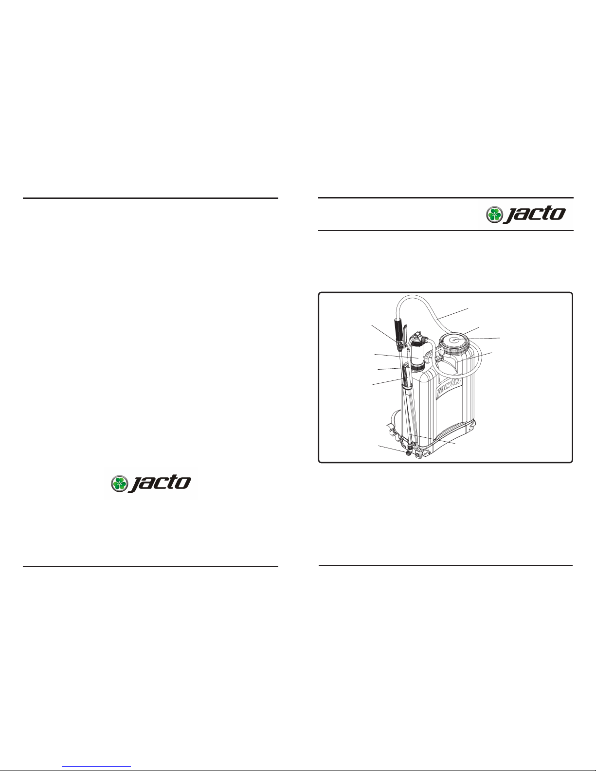
Tank
Lever
Rod
Chamber
Nozzle
2- SPRAYER VIEW
1- INTRODUCTION
This manual contains information for the proper assembly, operation and care of
your sprayer.
Carefully read and follow the instructions contained in this manual before using your
sprayer.
3- SPECIFICATIONS
Model .............................. CD 400 /
CD 500
Net weight (pounds) ....... 9.2 / 10.6
Tank
- Capacity (gallons) ......... 4.2 / 5.5
- Material .........................
Polyethylene (plastic)
- Filling opening diameter 4.5"
Pump
- Type .................................. Piston
- Material ............................. Brass
- Max working pressure ...... 65 PSI
Lance length ....................... 19.5"
Hose length ........................ 53"
Nozzle installed ................. JD-12P
Lance
Hose
Trigger valve
Diaphragm
Lid
STATEMENT OF LIMITED WARRANTY
MÁQUINAS AGRÍCOLAS JACTO S.A. shall warrant the equipment described
in this manual and shall repair or replace parts and components which, under normal
operation and wear, in accordance with technical recommendations, show DEFECTS
IN MATERIAL OR WORKMANSHIP, based on the following conditions.
WARRANTY PERIOD
- 01 (one) year from the date of sale to the original purchaser.
WARRANTY APPLICATION
- JACTO shall honor this warranty, free of charge, if any part or component shows defect
in MATERIAL OR WORKMANSHIP, after nal analysis at the factory.
THIS WARRANTY SHALL BE NULL & VOID IN CASE OF:
- Misuse of the equipment against specications in the OPERATOR'S MANUAL, overwork
or accidents.
- Preventive/remedial maintenance performed by unauthorized people.
- Use of parts and components not supplied by JACTO.
- Modication of the equipment or any characteristic of the original design.
THIS WARRANTY SHALL EXCLUDE:
- Parts which show wear and tear due to use, UNLESS THEY SHOW DEFECTS IN
WORKMANSHIP, ASSEMBLY OR MATERIAL.
- Damages resulting from accidents.
- Transportation or freight of the equipment, parts and components in case such warranty
is not approved.
- Transportation and mobilization of technicians.
GENERAL INFORMATION:
- Parts replaced within the warranty period shall be property of JACTO.
- The warranty on replaced parts and components shall expire together with the equipment warranty period.
- Eventual delays in performing services shall not give the owner right either to indemnity
or to extension of the warranty period.
- JACTO reserves the right to modify its products or to interrupt the manufacture without prior
notice.
10/2012- 1202909 - 0196-MI_USA
OPERATOR'S MANUAL
CD 400 / CD 500
JACTO INC.
19217 SW 119 th Ave.
Tualatin, Oregon 97062
Tel: (503) 885-8723
Fax: (800)511-3671
Toll free: (800) 522-8610
E-mail: [email protected]
Home page: www.jacto.com.br
Page 2
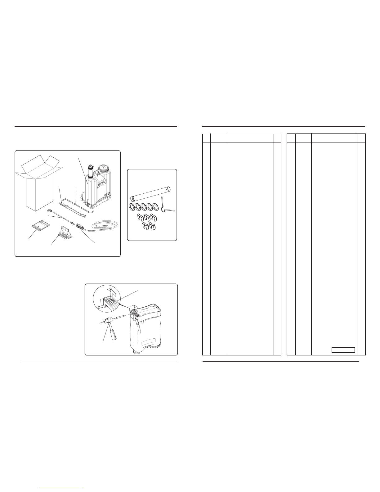
LLM-438
Contents of
the plastic bag
ATTENTION: Be careful taking the sprayer out of the carton as the lever is shipped
loose and can cause damage.
4- ASSEMBLY PROCEDURES
Remove from the sprayer carton the following parts:
02
Rod
Tank
Lance
5- INSTALLING THE SHAFT
- Insert the shaft (1) into the free ori-
ce on the sprayer base (chamber
side).
- Tap the shaft with a plastic hammer
as shown, until the hole on the shaft
end aligns with the hole on the base
reinforcement.
- Lock the shaft with the cotter pin
(2).
1
2
Accessories
plastic bag
Trigger
Valve
Lever
Manual
Base reinforcement
Hammer
Description
Item
Description
Item
Part no.
Qty
Qty
Part no.
15
0 878033 Sprayer CD400 1
0 878157 Sprayer CD550 1
1 1198800 Washers and Locked ring
set 1
2 942680 Chamber cover 1
3 573154 O-ring OR1-136 1
4 040964 Chamber nut 1
5 878074 Packing ring nut 1
6 831230 Packing ring 1
7 942722 Chamber body 1
8 878199 Chamber assembly (items
2, 3, 4, 7, 9, 10, 11, 12, 13
and 14) 1
9 743880
Piston cup
2
10 402297 Chamber valve 1
11 300582 Agitator 1
12 570929 Cylinder 1
13 715474 Ball 1
14 570945 Ball seat 1
15 336412 Compression spring 1
16 351486 Bolt M-6 x 20 x 1.0 2
17 570937 Cylinder base 1
18 336503 Screw 14 x 1" 2
19 743914 Flanged nut 1
20 570911 Cylinder assembly (Items
12-19) 1
21 573014 Padded strap & buckle 1
22 229971 Strap with handle 2
23 502757 Buckle 2
24 433474 Shoulder strap hook 2
25 635664 Shoulder strap lock 1
26 573006 Shoulder straps assembly
(Items 21-25) 1
27 1194579 Handgrip 1
28 661363 Pump lever 1
29 942896 Base clamp 2
30 878066 Half base 2
31 433870 Base reinforcement 1
32 211227 Screw 1/4" x 3/4" 2
33 433888 Shaft lock 1
34 433896 Pump lever shaft 1
35 878140 Split base (Items 29-34) 1
36 878041 CD400 Tank with lid (Items
37 and 40) 1
36A 878165 CD550 Tank with lid (Items
37 and 40) 1
37 942920 Strainer 1
38 837922 Tank lid seal 1
39 560573 Lid diaphragm 1
40 878132 Lid with diaphragm and
seal 1
41 942193 Screw cap S-20 x 1.5 1
42 048116 Hose with dip tube 1
43 909192 Trigger valve handle 1
44 920470 Lock 1
45 909283 Trigger valve body 1
46 105247 Trigger 1
47 105239 Trigger valve needle
assembly 1
48 996058 Trigger valve cap with
packing 1
49 908889 Trigger valve assembly 1
50 909309 Cone packing 2
51 915744 Screw cap 2
52 1149491 Tube (Stainless steel) 1
53 100131 Extension 601 1
54 635276 Elbow 1
55 592139 Nozzle lter (40 mesh) 1
56 217174 Nozzle JD-12P 1
57 229724 Nozzle cap 1
58 427062 Nozzle assembly (Items
55-57) 1
59 1198602 Rod with locked rings 1
Page 3
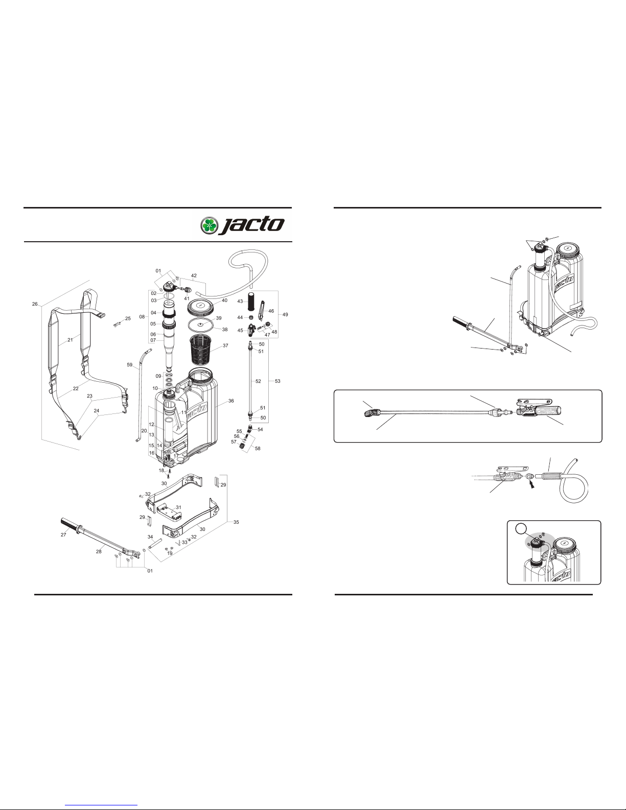
- Lightly grease the orice on the pump lever. Fit
a at washer on the rod end.
- Lightly grease the orice on the chamber top.
- Fit a at washer on the shaft and rod.
- For easy assembly, install the lever on
the shaft and the rod on the chamber
top at the same time.
- Install the other at washers on the
shaft and rod and lock with the
locked ring
14
6- INSTALLING THE LEVER ON THE SHAFT AND THE ROD ON THE CHAMBER TOP
Rod
Lever
Shaft
locked ring
Washers
Locked ring
Washers
03
7- ATTACHING THE LANCE TO THE TRIGGER VALVE
- Push the lance into the trigger valve and secure it with the screw cap.
Lance
Trigger
valve
Elbow
ATTENTION:
Do not overtighten the screw cap.
Screw cap
8- ATTACHING THE HOSE TO THE
TRIGGER VALVE
- Unscrew the trigger handle.
- Pass the hose through the handle and
lock and attach it to the trigger valve hose
barb.
ATTENTION: Do not overtighten the handle.
Trigger
valve
Handle
PARTS LIST
9- TIGHTENING THE FASTENING NUT.
- Before using the equipment, tighten the fastening nut
(A).
Important: This operation must be carried out with the
hand. Never use any type of tool.
A
Lock
Page 4
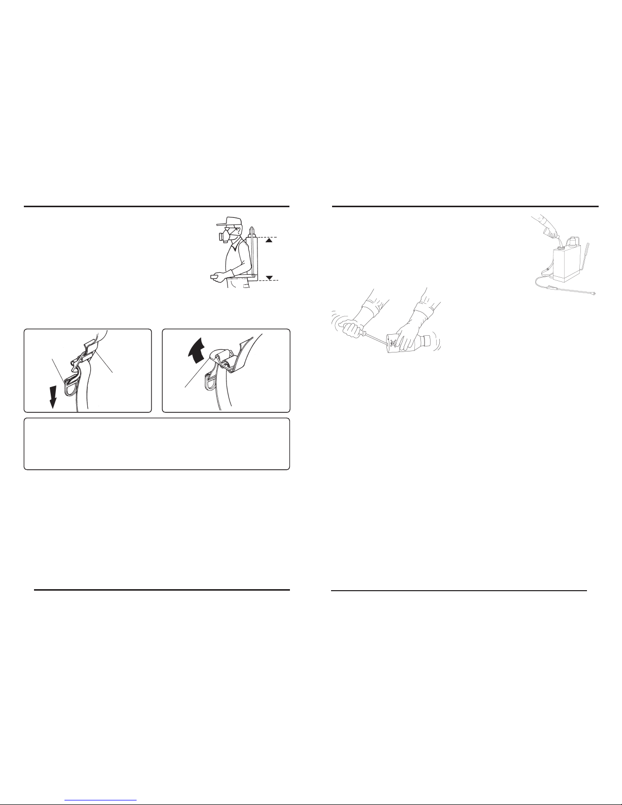
10- ADJUSTING THE SHOULDER STRAP
The tank is contoured for the operator comfort.
The shoulder straps can be quickly adjusted to properly
position the sprayer on the operator's back.
See below.
TIGHTENING
- Hold the strap buckle rmly with one hand,
and pull the handle downward with the other
hand.
Buckle
LOOSENING
- Hold the buckle rmly with one hand, and
pull the strap upward with the other hand.
Handle
Buckle
04
13
11- ATTENTION
After assembling the sprayer, ll the tank with clean water and pressure-check the
tank lid, diaphragm, tank base, lance and trigger valve for leakage. Most leaks can
be stopped by retightening the appropriate connections and ttings. Any leakage
must be repaired before returning the sprayer to service.
12- INVERTING THE LEVER OPERATING SIDE
This sprayer is assembled for installing the pumping lever for left hand operation. In case
you wish to invert to right hand operation, proceed as follows:
- Remove the locking rings (1), washers and rod (2) from the chamber top.
- Turn the chamber top 180 degrees.
- Reinstall the rod (2) on the chamber top, t the washers and secure the rod with the
locking ring again.
- Remove the locking rings (4) and (5) and washers.
- Remove the pumping lever (6).
- Take the container cap off and carefully pour the rinse water into
the spray tank.
- Continue holding the container over the spray tank opening
for approximately 30 seconds to the last drop.
- REPEAT this operation twice more. This way, you complete the
TRIPLE WASH.
- Next, make the plastic and metallic containers
useless by piercing with a pointed instrument the
containers bottom. This way, their labels are not
damaged for identication purposes.
- The useless containers can be placed temporarily in an appropriate place, until nal destina-
tion.
- In the case of mid and large size container (5, 25 and 50 gallon), after washing with the appropriate
volume (1/4 of the total) and tting the cap, roll it on the ground during approximately 30 seconds.
- In the upright position complete the agitation by moving back and forth for approximately 30
seconds.
- Empty the container by pouring the rinse water into the sprayer tank.
- REPEAT this operation twice more. Finally, totally empty the container by pouring rinse the
water in the spray tank.
- The least the amount of rinse water that remains in the container, from one wash to the next,
the better the decontamination will be.
- For the performance of the TRIPLE WASH, do not use a water volume either much lower or
much higher than 1/4 of the container capacity.
-The TRIPLE WASH must be done IMMEDIATELY AFTER emptying the container, during the
preparation of the solution
SOURCE - ANDEF (NATIONAL ASSOCIATION OF VEGETAL DEFENSE)
Page 5
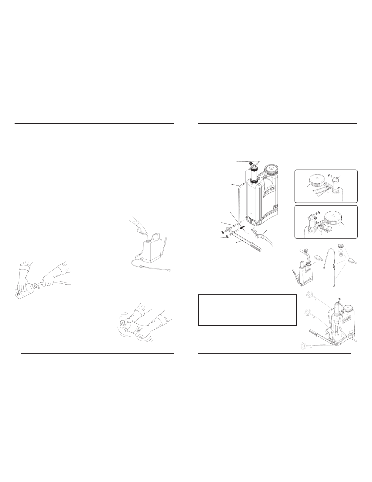
12
- Remove the shaft (7) and detach the shoulder straps (8) from both sides.
- Invert the positions as shown in the gure below (To install the shaft, follows instructions of the item 05).
-Install the washers and pumping lever on the rod so as to be operated with the right hand.
Locking ring (1)
(8)
(6)
(4)
Rod
(2)
(7)
(5)
- Invert the shoulder straps position
as shown below.
05
13- MAINTENANCE
CLEANING THE SPRAYER
- After nishing the spray application, clean and
wash all equipment in an approved decontamination area.
Pump the lever until the discharge runs clear.
ATTENTION:
Remove all chemicals before storing the
sprayer. Chemical products have different
reactions and can damage the sprayer compo-
nents as well as cause personal injury.
- Periodically, clean the chamber and lubricate the
components as shown.
- Remove the chamber and lubricate the piston cups.
Even the containers considered empty contain chemical residues.
Some publications show that somewhere around 0.3% of the chemicals remains in the
container after being used.
Therefore, discarding the containers without washing out the residues is extremely dangerous to man, animals and environment.
In the case of metal, plastic and glass chemical containers, each container must be rinsed
three times to ensure the residues are completely removed.
This manual describes how to make the TRIPLE WASH in a correct, safe and effective
way.
-During the TRIPLE WASH, you must use appropriate protective clothing, such as: gloves, apron,
boots, goggles and protective masks with appropriate lters.
- IMMEDIATELY AFTER emptying the container, you must keep it with
the opening upside down over the sprayer tank opening or over the
bucket that you are using to prepare the chemical mixture for at least
30 seconds, until no residue is left in the container, when the drops are
falling in long intervals.
- Next, hold the container in the upright position and ll it
with water up to 1/4. For example: in a 4 gallon container,
put 1 gallon of water.
- Fit the container cap and tighten enough to avoid leakage
during the agitation.
- Agitate the container vigorously in all directions (horizontal
and vertical), for approximately 30 seconds to remove the
residues that cling to the container internal walls.
TRIPLE WASH OF EMPTY AGROCHEMICALS CONTAINERS
Page 6
06
- Do not eat, drink or smoke while spraying.
- Do not pollute the environment.
- Keep the pro-
ducts out of reach
of children and
animals.
ATTENTION: The clothing used during the application must be washed separate
from other clothes of ordinary use.
- After nishing the spray application, take
a shower with plenty of water and soap.
- Put on clean clothes.
- Lock up the chemical products to prevent
untrained persons to from handling them.
ATTENTION: In case of poisoning, see a doctor immediately and show
him the chemicals manufacturer's label.
11
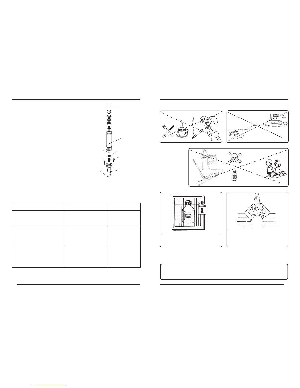
CORRECTION
CAUSE
PROBLEM
Worn or dried out piston cup.
Leakage through the cylinder
upper part (1).
Lubricate or replace
the piston cup.
After pumping and pressurizing
the chamber, the lever drops
Cylinder valve (2) not sealing
properly due to wear or impu-
rities.
Clean or replace
the valve.
15- TROUBLESHOOTING
- Pour about 0,5 gallons of clean water into the tank.
- While operating the pumping lever, look inside the tank to investigate the problem.
- Refer to the table and diagram below.
After pumping and pressurizing
the chamber, the lever rises
slowly when released.
Clean or replace
the valve.
Chamber valve (3) not sealing properly due to wear or
impurities.
Chamber
1
7
6
Cylinder (2)
5
4
3
14- CYLINDER MAINTENANCE
DISASSEMBLING
- Remove the chamber from the cylinder.
- Remove the nuts (1) from the cylinder.
- Remove the cylinder (2).
- Loosen the bolts (3), remove the spring (4), ball seat
(5) and ball (6).
- Clean or replace the parts that show wear.
ASSEMBLING
- Install the ball, ball seat, spring and bolts (3) on the
cylinder base (7).
- Next, position the base (7) on the cylinder (2) and
secure it with the bolts (3).
- Install the complete assembly on the sprayer and secure
it with the nuts (1).
Page 7
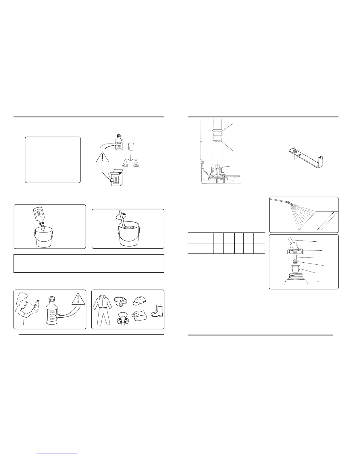
SAFETY PRECAUTIONS
- Read carefully the chemicals
manufacturer's label.
- Use of individual protective clothing and
safety equipment is required.
ATTENTION
- Wash hands and other parts of the body that have touched chemicals before starting
to spray.
Chemical
product
- Stir until it becomes an homogeneous
mixture.
- Pour the solution into the tank while lling
with water.
- Put 1.5 gallons of water in a bucket and
add the chemical product.
ATTENTION!
READ CAREFULLY
THE CHEMICALS
MANUFACTURER'S LA-
BELS
10
07
Wrench for maintenance of
chamber and cylinder valve.
(OPTIONAL).
CALIBRATION OF MANUAL KNAPSACK SPRAYER
PROCEDURE
USING CALIBRATOR BOTTLE (OPTIONAL)
- Hold the lance at the working height and
spray to measure the application band width.
- Based on the band width, calculate the total
walking distance required to spray the desired
area. Use the chart below.
Band
width
Lance
Cover
Filter
Nozzle
Nozzle cap
Calibrator
bottle
- Attach the calibrator bottle to the lance as
shown:
A - Remove the cap, nozzle and lter.
B - Mount the calibrator cover to the lance.
C - Reinstall the lter, nozzle and cap.
D - Screw the calibrator onto the cover.
- Hold the lance at the normal working height and spray into the bottle while walking the
distance required to spray an area corresponding to 269.1 ft.
- Place the bottle on a level surface and observe the liquid level visible through the side
of the bottle. Match the liquid level to the corresponding scale on the calibrator bottle.
- Empty the bottle and repeat this operation to determine the average of two or more
readings.
1
3
2
Part # : 452284
1.6 2.2 3.2 3.9 4.9
164 117.1 82 68.2 54.7
Band width
(feet)
Distance to
walk (feet)
Page 8
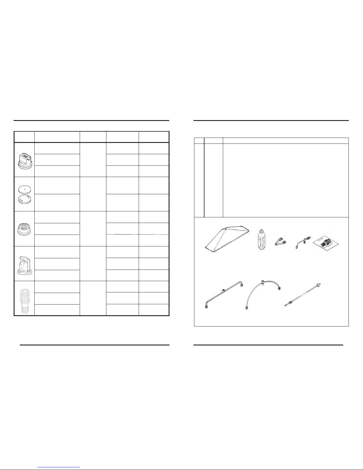
SPRAY NOZZLES
Flat fan
IDENTIFICATION
(Part no. - Description)
NOZZLE
TYPE
(1197536) JEF 11002
Yellow
(1197535) JEF 110015
Green
(1197537) JEF 11003
Blue
Herbicides
Cone
Cone
Flat fan
Deector
Adjustable
Cone
Agrochemicals
and foliar fertili-
zers.
90º cone
and concentrated
jet
45 0.16
45
0.21
45
0.33
45
717942 - JD-10A
(Stainless steel)
(*) 217174 - JD-12P
(Stainless steel)
0.08
0.16
45
Agrochemicals
and
foliar
fertilizers
APPLICATION
PRESSURE
(psi)
FLOW RATE
(gallons/min)
(1197565) JHC 8002
Yellow
45 0.22
(1198892) JHC 8004
Red
Agrochemicals
and
foliar
fertilizers
45 0.44
(1198893) JHC 8005
Brown
45
0.54
(1197486) JDF 11004
Red
(1197488) JDF 11006
Gray
(1197487) JDF 9005
Brown
Agrochemicals
and
foliar
fertilizers
15 0.25
15 0.31
15
0.41
45 0.08
45
0.17
45 0.18
323725
(Yellow)
015024
(Red)
325787
(Blue)
* ATTENTION: This sprayer is packaged with the JD-12P nozzle assembled on the lance.
Other nozzles mentioned in this manual are optional, and can be purchased separately.
0908
01 761882 Spray guard: prevents nonselective herbicides from drifting.
02 902296 Boom 500: improves the coverage and increases the productivity.
03 907873 Flexible boom: holds the required shape for better coverage.
04 728139 Extension 600: increases the application reach.
05 100016 Extension 160 - 2 nozzles: increases the coverage and penetration.
06 834309 Flow calibrator bottle: is used to calibrate the sprayer, thus
reducing the waste
07 336115 Nozzle Y: improves the coverage.
08 1197164 Ecovalve green 15 PSI (1,0 kgf/cm2)
1197159 Ecovalve yellow 22 PSI (1,5 kgf/cm2)
1197163 Ecovalve blue 30 PSI (2,0 kgf/cm2)
1197162 Ecovalve red 45 PSI (3,0 kgf/cm2)
OPTIONAL ACCESSORIES FOR MANUAL KNAPSACK SPRAYERS
Item
Part no.
Use
Boom 500
Spray guard
Pliable boom
Extension 600
Ecovalve
Extension 160
Nozzle Y
Flow
calibrator
bottle
 Loading...