

Page 1

ADVANCE 2000 AM-18
ADVANCE 2000 VORTEX
English version /MI_USA 0250
Edition: 07/2017
Code: 825083
Operator’s Manual
Máquinas Agrícolas Jacto
Rua Dr. Luiz Miranda, 1650
17580-000 - Pompéia - SP - Brasil
Tel.: +55 14 3405-2100
CNPJ: 55.064.562/0001-90
e-mail: [email protected]
www.jacto.com.br
Page 2

Page 3

ADVANCE 2000
Introduction ......................................................................... 5
Precautions ....................................................................... 1-7
Assembly .........................................................................2-27
Technical Specifications ....................................................3-47
Operations and Adjustments ...............................................4-53
Maintenance ....................................................................5-83
Table of contents
Warranty ........................................................................ 6-111
General Index of tables ...................................................... 119
3
Page 4

Page 5

ADVANCE 2000
Introduction
JACTO has an ongoing concern for the safe and
effective use of chemicals.
This concern is indispensable, for the use of
chemicals has become a necessary practice for
obtaining a more productive and more economical harvest.
ver, the improper application of chemi-
Howe
cals is harmful to the human being, the environment and the cultivations themselves.
ATTENTION!
The Advance 2000 equipment has been developed for the exclusive use of spraying
chemicals.
The Jacto Advance 2000 sprayer manual refers only to instructions for use and maintenance of parts and components made by Jacto.
Read it carefully and follow the recommendations contained herein. In case of
doubt, please contact JACTO.
J
ACTO’s aim is to prepare and guide the farm-
er on the proper use of the farm equipment
ufactured by JACTO.
man
Therefore, read carefully and understand
thor-oughly this manual before operating this sprayer and keep it always at hand
when handling this sprayer for quick consultation in case you are not quite sure of some
operation or adjustment.
If you still have questions, contact your Jacto dealer.
PRECAUTIONS
Identification plate
JACTO is the registered trademark of MÁQUINAS AGRÍCOLAS JACTO S.A.
MÁQUINAS AGRÍCOLAS JACTO S.A. implements a policy towards the ongoing enhancement of its products. Therefore, it reserves the right to change its products without prior notice and without incurring in any obligation whatsoever in connection
with such changes.
The machine model, serial number and lot
(manufacturing month and year) are printed
on the machine identification plate.
This information is important to enable us to
keep records on modifications, if any, made
to the material employed and construction
characteristics of the machine.
When ordering replacement parts and maintenance services, it is essential to inform the
machine model, number and lot in order to
get an expeditious and efficient response.
5
Page 6

Page 7

ADVANCE 2000
Introduction ..................................................................... 1-9
Operator and owner’s responsabilities .................................1-10
Table of contents
1
Environmental responsibilities ............................................ 1-11
Safety decals ...................................................................1-12
General safety recommendations ........................................1-15
Safety for unloading the equipment.....................................1-17
Cautions during component assembly ..................................1-18
Warning when using and filling the tank ..............................1-20
Safety in applying chemicals ..............................................1-21
Safety on maintenance ......................................................1-25
Transportation safety ........................................................1-26
PRECAUTIONS
1-7
Page 8

Page 9

ADVANCE 2000
Introduction
1
Chapter ‘Precautions” is intended to guide
the operator on the cautions to be taken during the operation, maintenance and storage
of this equipment.
It is important to remind that this equipment
has been carefully developed to provide optimum performance with cost savings, and
ease of operation and safety.
For that purpose, be always mindful of the
information contained in the instructions
manual. If doubts arise at any time, please
contact us.
The instructions in this manual may be accompanied by symbols having the following
meanings:
ATTENTION: a
accident hazard situations that require
permanent operator’s attention.
dvises of potential
NOTE: reminders or warnings.
PRECAUTIONS
OBSERVATION:
plains certain instructions/situations.
advises of or ex-
ATTENTION!
By disregarding the safety practices you are risking your life
and the life of all people around
you. This manual contains important safety warnings. Read
it carefully and be aware of any
possible personal accident.
1-9
Page 10

1
Operator and owner’s responsabilities
ADVANCE 2000
PRECAUTIONS
According to the provisions in Directive NR31 –
Directive on Safety and Health in Farming Labor,
the farm equipment owner and operator shall
contribute to the safe application of chemicals
and other agro-chemicals, by observing the
legal determinations outlined below.
Operator’s responsabilities:
• Comply with the determination regarding
safe manners for performing his/her activities;
• Operate the equipment within the operating limits and restrictions specified in
this manual;
• Read this manual and make sure that all
information and recommendations have
been understood before putting this equipment in operation
Owner’s responsabilities:
• The equipment owner shall keep the ins-
tructions manual at a place where the
operator can have free access to it whenever necessary.
• Whenever dictated by the kind of defensive to be sprayed, the employer has the
obligation of providing the operator with
the appropriate PPE – Personal Protection Equipment, see that the PPE is properly hygienized, train the employee and
enforce and inspect the use of the PPE.
• The owner shall replace or repair components of the equipment whenever such
components exhibit defects hindering the
safe operation of the same.
• The owner or whoever in charge shall
take responsibility for qualification of the
equipment operators in order to guarantee the safe operation thereof.
1-10
Page 11

ADVANCE 2000
ATTENTION!
It is responsibility of the sprayer owner and sprayer user/operator to comply with
the laws and regulations in effect. The sprayer owner or the person responsible
shall provide information to operators on environmental risks and how to care for
the environment. Jacto recommends wearing approved and proper PPEs whenever
operating the sprayer.
Environmental responsibilities
1
PRECAUTIONS
• It is responsibility of the sprayer owner
to comply with the laws and regulations
in effect.
• Waste such as contaminated parts, electrical and electronic components, and
other
s when equipment (sprayer) is dismantled after rendering services, being
serviced or a the end of their useful lives
must be disposed of in a way that respects
the environment, avoids air, water and
soil pollution.
• If necessary, residues must be stored in
proper places and later collected by trained
and authorized employees or companies.
• Principles for environmental protection,
recycling and proper disposal of equipment, its parts and components must be
espected taking into consideration the
r
legislation in effect (municipal, state and
federal) as well as guidelines to dispose of
parts, components or any other item of
the equipment.
• Batteries must be properly disposed of
in places which have been approved to
collect such material. Legally speaking,
places that sell new batteries can collect
used ones and take them to recycling centers or to their manufacturers. If you are
not sur
environmentally sound manner, JACTO
suggest contacting their manufacturer for
further information.
• JACTO recommends wearing proper and
approved PPEs at all times when handling
the equipment.
e how to dispose of batteries in an
1-11
Page 12

1
Safety decals
ADVANCE 2000
PRECAUTIONS
Safety and maintenance related decals have
been affixed all over the equipment indicating
any hazardous conditions that could cause
damages or accidents affecting the operator
or the equipment during operation.
Before operating your equipment, identify all
decals and by reading these pages make sure
that you have understood and are aware of
the meaning of each such symbol.
P/N: 276220
ATTENTION: Lubrication
point
P/N: 276238
Keep them in good repair, clean and legible.
Replade them immediately in case of damage
by ordering them through the part numbers
specified below.
P/N: 379065
ATTENTION: Risk of serious
injuries. Keep all protection
devices in its places.
ATTENTION: Area where
the jack must be placed to
lift the equipment.
P/N: 379248
ATTENTION: Read the
operator’s manual before
operating the sprayer.
P/N: 379230
ATTENTION: Read the
operator’s manual
before operating
the sprayer.
P/N: 379115
ATTENTION: Obligatory use
of protective mask.
P/N: 379149
ATTENTION: Tire pressure table.
1-12
P/N: 998328
ATTENTION: Keep at a
distance, risk of collision.
P/N: 379164
ATTENTION: Nut
torque table.
Page 13

ADVANCE 2000
P/N: 379123
ATTENTION: Obligatory use
of hearing protector.
P/N: 379131
ATTENTION: Obligatory use
of protective clothing.
Safety decals
RG: 379057
ATTENTION: Risk of serious injuries. Keep away
and do not make any kind
of maintenance while the
fan is in motion and the
PTO is engaged.
P/N: 379008
ATTENTION: Risk of serious
injuries. Do not make any
operation on the PTO shaft
if the PTO is engaged.
1
PRECAUTIONS
P/N: 379073
ATTENTION: Clean water
tank to wash the hands.
P/N: 379222
ATTENTION: This machine
is not allowed in highways.
P/N: 380014
ATTENTION: Do not get
into the main tank of
the sprayer.
P/N: 379214
ATTENTION: Maximum
speed allowed for the machine is 30 km/h .
1-13
Page 14

1
Safety decals
ADVANCE 2000
PRECAUTIONS
P/N: 379024
ATTENTION: Read the
operator’s manual of the
sprayer before operating
the steel cables.
P/N: 378992
ATTENTION: Risk of serious
injuries. Do not maneuver
the sprayer close to electricity
supply cables.
P/N: 379032
ATTENTION: Read the
operator’s manual of the
sprayer before operating the
steel cables.
P/N: 379172
ATTENTION: Be careful
when opening the lid of
the main tank.
P/N: 379040
ATTENTION: Risk of injuries.
Keep away from the sprayer
when it is running.
P/N: 379016
ATTENTION: Flow control
directional valve. It directs
the ow of the 200 or
3000-liter tank to the
chemical pump.
P/N: 997965
ATTENTION: Actuation of the Vortex
system fan.
P/N: 379107
ATTENTION: Hydraulic oil
level indicator.
P/N: 378976
ATTENTION: Read the
operator’s manual
of the sprayer before
operating the
steel cables.
P/N: 378984
ATTENTION: Read the
operator’s manual
of the sprayer before
operating the
steel cables.
1-14
Page 15

ADVANCE 2000
General safety recommendations
1
• Only skilled and qualified operator and
knowledgeable of the information contained in the manuals accompanying the
product should operate the Advance 2000.
• Before starting any operation, it is very
important to learn about all information
contain in this manual. In case of doubt,
refer to Jacto’s technical assistance.
• Do not ingest alcoholic beverages, tranquilizers or stimulating substances both
ore and during work.
bef
• During manipulation of the setup, always
use approved, recommended and appropriate PPEs such as: long-sleeve overalls,
waterproof coat or apron, waterproof gloves, waterproof broad brim hat, boots and
special pr
ters suitable for each kind of product. In
case of
contact the manufacturer of the same.
• When checking the machine components
that are in direct contact with the farm
chemicals, use approved PPEs and according to the recommendation stated on the
pr
oduct label.
otection masks provided with fil-
doubts, read the chemical label or
PRECAUTIONS
• If the tractor is of the cab type and provided with air cleaning system, clean your
ootwear and remove contaminated clo-
f
thing. Keep the same outside the cab within a properly sealed container.
• If recommended by the tractor manufacturer, use ear protector.
• Use approved, recommended and suitable breathing mask if the label on the
chemical requires such personal protection equipment.
• Redouble the precautions. Keep away from
places where obstacles exist such as trees,
stones, holes, erosion ditches, electric network, etc.
1-15
Page 16
1
General safety recommendations
ADVANCE 2000
PRECAUTIONS
• Use under adverse and not recommended conditions can compromise the integrity of the equipment and components,
entailing loss of warranty and disclaimer
by the manufacturer for any accident and
the resulting consequences.
• Avoid parking the equipment on slopes. If
necessary, place chocks under the wheels
when parking the equipment on upward
or downward slopes.
• Keep the ladder, platform and handrail always clean; oils and greases can
cause accidents.
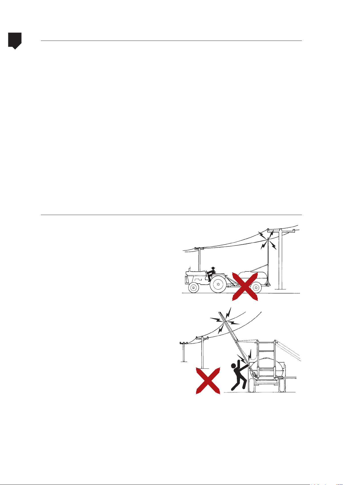
Electricity supply cables
• Do not use the equipment if some critical
component needs to be repaired. Provide
for the repair before.
• This equipment can cause accidents if
used improperly or irresponsibly.
• Do not step on the machine while it
is moving.
• Attention when passing next or under an
electricity supply cables. In case of doubt,
change the course.
• Never fold and unfold the booms close to
the electricity supply cables.
• The sprayer must be trailed by the tractor
in the farm with the spray booms folded
and locked. Always place the sliding frame at the lowest position (rest position of
the fixed frame).
• Remove the booms of the sprayer before
transporting it by wagons or trucks.
1-16
Page 17

ADVANCE 2000
Safety for unloading the equipment
1
• Unloading shall take place at spots specifically created for unloading such type of
equipment. Do not impr
ding the equipment.
• Wear the PPEs during removal of the ropes fastening the equipment to the cart.
If the equipment is not new, make use
of a combination of the mandatory PPEs
for unloading the equipment (e.g., safety
boots, gloves, hardhats, etc.) and mandatory PPEs for chemical spraying (e.g.,
masks, gloves, etc.) in order to reduce the
risk of contamination and accidents.
• For unloading the equipment, use a
tractor having the capability to carry out
such task. Selection of the tractor shall
take into account its drag capacity and
spraying mechanism weight.
ovise for unloa-
• Do not untie the mobile parts of the equipment, for instance: PTO shaft, before unloading the equipment down from the truck
or cart and position it on a safe place.
• After placing the equipment on a safe place and far away from electric mainlines,
eset the jack to its rest position and un-
r
couple the equipment from the tractor.
• Require from the JACTO representative during the technical delivery of the sprayer that
oper instructions on assembly, main-
the pr
tenance, warranty be carefully explained.
PRECAUTIONS
Precautions when coupling the equipment on the tractor
• Refer to the tractor instructions manual
before carrying out this operation. The
precautions listed below apply only for
coupling the Advance/Advance Vortex to
the tractor. Precautions related to the use
and adjustments to tractor components
are the responsibility of the tractor manufacturer and user.
• Information related to the proper adjustment of the three points and procedures
for properly coupling the equipment will
be outlined in chapter 2 “ASSEMBLY” of
this manual.
• The operation for coupling the equipment
to the three points may be performed by
more than one individual. In such case,
the people engaging in the operation shall
be aware of the risks, be trained, qualified
and skilled and possess the necessary experience in this kind of work.
• Avoid staying in the way of the tractor
tires. If possible, carry out the coupling
of the equipment by yourself.
• Before stepping down of the tractor for
coupling the equipment, apply the parking brake. Shut down the diesel engine
and remove the starting key from the
contact keyhole.
• After the coupling, carry the equipment
to the place where the components will
be assembled thereon.
• The PTO shaft ends must be securely
locked to the PTO of the tractor and to
the sprayer tongue.
• The PTO shaft guard must always remain
in good repair and fastened by the safety
chains. The PTO shaft must work freely in
its interior.
• Make sure the drawbar and the sprayer
end are properly connected/fastened.
1-17
Page 18

1
Cautions during component assembly
Warning for adjusting and connecting PTO shaft to the tractor
ADVANCE 2000
PRECAUTIONS
• Refer to the tractor user manual before
performing this operation.
• Turn off the tractor diesel engine, apply
the parking brake and remove the starting
key from the contact keyhole before
coupling the PTO shaft to the tractor PTO.
• Try to couple the PTO shaft to the tractor PTO.
If necessary to adjust the PTO shaft length,
use the PPEs specific to this operation such
as: goggles, gloves, boots, etc.
• When coupling the PTO shaft to the
tractor, make sure that the safety pin is
securely locked.
• Directions on how to properly adjust
the PTO shaft length will be described in
chapter 2 “ASSEMBLY” of this manual.
• After length adjustment, clean and
lubricate the PTO shaft components.
Wear safety gloves for this operation too.
• Never use a PTO shaft not fitted with
shroud.
• The PTO shaft will be adjusted to its
specific use on the Jacto BC 610 PEC
equipment. Use of the PTO shaft on any
other equipment is not recommended.
• Do not perform adaptations for reutilization of the PTO shaft.
• Fasten the PTO shaft covering safety chain
to the tractor; that chain will prevent the
PTO shaft covering from turning together
with the PTO shaft.
• Before actuating the tractor PTO, fill the
main reservoir.
1-18
Page 19

ADVANCE 2000
ATTENTION!
By disregarding the safety practices you are risking your own life and the life of all
people around you.
This manual contains important safety warnings. Read it carefully and be on the
alert to any possibility of personal accident. Keep all decals affixed to the machine
and replace the same if necessary.
Safety for unloading the equipment
1
PRECAUTIONS
• The improper handling by untrained people can give rise to serious or fatal accidents.
• Do not perform adaptations or improvisations; they compromise your equipment and put your safety at risk.
• Do not allow children, aged people or
animals to stand close to the equipment
during use, maintenance or even with
the equipment stored.
• Keep hands, feet, loose clothing and long
hair away from moving parts.
• Before performing any kind of service,
adjustment or maintenance to your
equipment, switch off the power takeoff and the tractor engine.
• If the equipment was used, even if it
has been washed and looks quite clean,
wear all PPEs recommended for handling the chemical.
• Do not touch PTO shafts, belts, fans or
any other moving parts of the equipment
with the PTO coupled of the tractor diesel
engine running.
• When uncoupling the machine, hold it
on firm and level ground; if the equipment is provided with parking brake, actuate the same!
• Do not allow the power take-off to operate in excess of 540 rpm.
• Keep the machine in perfect upkeep at
all times.
• Safety-related decals were applied across
the equipment to orient on the risk of
damage or accident that may occur to the
operator or equipment.
• Request a JACTO representative during
the technical delivery of the equipment
for a proper assembly instructions, maintenance, warranty instructions to be carefuly explained.
• Use of PTO shafts not provided with protection covering is strictly forbidden.
• Do not make maneuvers or brake abruptly.
• The transportation of people and any
loads whatsoever in the sprayer is strictly prohibited in any circunstances.
• This sprayer was designed and manufactured to support operations in the crops
and on roads, tracks, trails or paths inside farms within the speed limit recommended by Jacto (limit of 30 km/h in the
routes inside the farm and 12 km/h when
spraying). The use of the sprayer above the
limits mentioned is not approved by Jacto.
• Do not operate the pump without liquid.
1-19
Page 20

1
Warning when using and filling the tank
Fresh water tank for hand wash
ADVANCE 2000
PRECAUTIONS
• Abasteça o tanque de água limpa para lavagem das mãos apenas com água limpa.
A utilização de detergentes ou soluções é
expressamente proibida.
• Em hipótese alguma a água desse reservatório deverá ser ingerida ou utilizada
para outros fins.
600-liter reservoir
There are two methods for supplying the
600-liter water reservoir. The instructions for
this operation are described in chapter 4 “OPERATIONS AND ADJUSTMENTS” of this manual. Following are the precautions to be taken
when supplying this reservoir:
• During the 600-liter reservoir supply operation, it is extremely important that all
those engaged in the operation be using
the specified PPEs. It is very important to
read the label of the chemical being used
in the application. You will find on that
label several information on the product
and precautions to be adopted, etc.
• É extremamente importante que esse reservatório seja mantido sempre cheio.
• The setup residue remaining inside the
supply hose shall be collected with a bucket and returned to the reservoir which
the mixture was prepared in. Do not let
this residue to drop on the ground.
• Do not contaminate water springs. Supply of the sprayer shall be carried out at
places designed for that purpose.
• Avoid capturing water from sources such
as rivers, lakes, dams, creeks, etc.
• By following these recommendations,
you will be preserving the environment.
1-20
• Before beginning to supply the 600-liter
reservoir, make sure that the reservoir
drain valve is shut.
Page 21

ADVANCE 2000
Safety in applying chemicals
• READ the sprayer instructions manual.
For an efficient spraying operation, it is
necessary to know the sprayer employed
in detail. Only thus will we prevent wasting chemical or improper use of the
equipment, and the desired result will
be achieved.
• USE the chemical products in agriculture only.
• READ and FOLLOW all instructions on the
chemicals manufacturer’s label.
• HANDLE the chemicals following recommendations of a technician.
• Proper SETTING of the sprayer is a simple
operation. Only with the sprayer properly
set will the best results be achieved.
1
PRECAUTIONS
• USE approved, recommended and suitable
protection equipment (PPEs). During handling, setup of the mixture or spraying, use
all pr
otection equipment recommended by
the chemical manufacturer.
• AFTER the spraying operation, take a
shower and change clothing. The used
clothing shall be immediately washed
and segregated from the regular use
clothing to eliminate the chemical residue. In case of contact with chemicals,
wash the affected part with running water for at least 15 minutes. Remember:
most contamination cases occur at the
time of setup of the mixture, where the
chemical is still concentrated, and gets in
contact with the hands.
• DO NOT enter with or keep inside the tractor cab the personal protection equipment
(PPEs) used during handling or setup of the
mixture in order not to contaminate the
place. When inside the tractor cab during
operation of the machine and/or spraying operation, use only an ear protector. If
noticing that contamination has occurred
(if feeling chemical smell) caused by carelessness in working with the door open or
1-21
Page 22

1
Safety in applying chemicals
letting contaminated materials coming in
(e.g.: PPEs), use immediately an approved
and suitable breathing mask and contact
Jacto’s Technical Assistance;
ADVANCE 2000
PRECAUTIONS
• IF the manufacturer of the product to be
used recommends using a breather mask
during application, use it!
• KEEP the sprayer in perfect condition:
Make sure that no leaks exist. If detected, eliminate the same! Leaks not only
represent chemical waste but also uneven application and contamination of
the environment.
• USE the appropriate nozzle: There is an appropriate nozzle for each chemical to be
a
pplied. Climate conditions will also influence nozzle selection. The mixture volume
varies fr
The chemical manufacturer should be
consulted for the optimum nozzle option.
• DO NOT clear nozzles, vales or tubing
with your mouth: Use protection gloves
for this operation. Any spraying equipment contains chemical residue.
om one chemical to another one.
1-22
• NEVER let sprayer parts contact your
mouth; this is the fastest means of contamination. If need arises to clear the
nozzles, one may also employ a nylon
bristle brush (toothbrush).
• DO NOT contaminate water sources: The
spraying mechanism refill shall be performed at places designed for that purpose or by means of appropriate refilling
vehicles (tr
water from sources such as rivers, lakes,
dams, creeks, etc. with the aid of the sprayer return system. PRESERVE THE ENVIRONMENT!
• DO NOT eat, drink or smoke: when handling the mixture or during application
of the chemical, keep foodstuff far away
from the treated areas.
ucks, carts, etc.). Avoid capturing
Page 23

ADVANCE 2000
Safety in applying chemicals
• KEEP children away from the sprayed areas. Remove children, domestic animals
and unprotected people from the treated areas. Do not allow children or other
persons not necessary for the services to
remain in the chemical handling and application areas.
• APPLY the recommended dosages: The
dosages recommended by the manufacturers shall be followed. Any change to
the dosage or calculation error may bring
about serious consequences to the cultivation or the environment. Do not use
chemicals in cultivations which the same
have not been recommended for.
• DO NOT spray with strong winds blowing over the area: Excess wind can cause
many problems. It will prevent the chemical from reaching its target, causing a poor
distribution of
tion; it can also carry the sprayed mixture
to
water springs, wild animals and the
entire environment. Do not spray if the
wind velocity is higher than 10 km/h. Do
not spray in the absence of winds. Such
a situation can cause a thermal reversal.
A good application can be obtained with
winds blowing at 3 to 7 km/h velocity,
temperature from between 7 and 30°C
and relative air humidity over 55%. Do not
spray against the direction of the wind or
during the day warmest hours.
chemical over the cultiva-
1
PRECAUTIONS
• WASH the packaging before disposing the
same. When preparing the mixture, wash
the used packaging for about 30 seconds.
• TO NOT reuse empty packaging; Even after several washing operations, chemical
packaging still retain residue. Do not burn
empty packaging material. After washing, render the same unusable (pierce
the packaging bottom) and store it at a
safe place until the same are picked up
ad recycled.
1-23
Page 24

1
PRECAUTIONS
Safety in applying chemicals
• NEVER fill the sprayer to the top. By doing so, you will prevent the mixture from
overflowing and possible contamination
of the operator and the environment.
When supplying the reservoir, do it up to
the maximum limit indicated in its graduated scale.
• When CARRYING chemicals: Never carry
them close to foodstuff or animal feed.
Never buy packaging exhibiting leaks.
Never buy or use chemicals past their
shelf life. Never carry chemicals inside
the cab. If an accident occurs causing
chemical spill, take steps towards preventing the chemical from running into
lakes or rivers. Notify the authorities and
the chemical manufacturer.
ADVANCE 2000
• STORING THE CHEMICAL: Build a brickwork storehouse for chemicals.
• LINE THE FLOOR with waterproof material. Do not rest the product piles on the
floor or against walls. Use a footboard.
Keep at the place a drum with sand to
absorb leaks, if any. Install faucet and
shower outside the storehouse for the
chemical appliers.
• SYMPTOMS of intoxication: unconsciousness, anxiety, convulsions, weakness,
headache, indisposition, dizziness,
blurred vision, qualms of nausea, vomits, belly ache, diarrhea, urine with different color and consistency; eye, nose and
throat irritation, cough and tears.
• FIRST aid: if the victim vomits, let him/
her stay sitting. Never serve any alcoholic beverage or milk to intoxicated
(poisoned) persons. Keep the victim calm
and in a comfortable position. Find the
chemical label. Call a doctor.
1-24
Page 25

ADVANCE 2000
Safety on maintenance
1
• Awareness of and compliance with the recommendations contained in this manual
educe the maintenance costs and ex-
will r
tend the service life of the equipment.
• The maintenance services shall be carried
out by qualified and skilled professionals.
Even if the equipment has been washed,
it will be necessary to wear the following
PPEs: long-sleeve overalls, waterproof coat
or apron, waterproof gloves, goggles and
boots and special protection masks provided with appropriate filters.
•
Use original parts, for they warrant a perfect
operation of the equipment.
• Maintenance services shall be performed
with the equipment coupled to the tractor,
with the tractor wheels chocked and the
diesel engine and tractor PTO shut down.
• Do not make improvisations nor use inappropriate tools during maintenance to the
equipment.
• Lubricating oil filters and oils shall be
checked from time to time and changed
whenever necessary or recommended.
• Every maintenance service on hydraulic
tubing or hoses shall be performed after depressurization of the circuit. Redouble your
warning during this kind of maintenance.
• The identification of spots exhibiting possible leaks shall be made with paper, never with the hands.
•
With the equipment coupled to the trac-
tor and the PTO, be careful and keep away
from the moving parts of the equipment;
these must be provided with their respective protections. In case of doubt, call the
authorized technical assistance.
• In case that no possibility exists of providing maintenance service to the equipment
with the diesel engine shut down and outside sheds, keep the shed doors and windows wide open to allow continuous circulation of air. Internal combustion engines
running within closed environments cause
toxic gases and can asphyxiate the operator within a few minutes.
• Performance of cleaning, lubrication and
maintenance services with the machine
running is forbidden, unless such running
condition is indispensable for the performance of such operations, in which case
special pr
be taken against occupational accidents.
• Welding services on bars, chassis or other
metal parts of the equipment may only be
performed after removal of the tractor battery cables and after draining and washing
of the chemical reservoir.
• Keep the machine decals in perfect repair
at all times. They contain important notices
and recommendations.
• The removable protectors shall only be removed for cleaning, lubrication and repair
or adjustment operations. Once the service
is completed, they shall be put back.
• The component lubrication work shall be
carried by a skilled, qualified and authorized individual. Such procedure involves
a number of risks such as slipping, contamination, etc. During the procedure,
use of gloves, goggles, boots provided
with antiskid sole is recommended. If the
equipment has been used, use also approved and appropriate breather mask.
• Do not enter in the 600–liter reservoir. If
necessary, call the specialized technical
assistance.
otection and signaling steps shall
PRECAUTIONS
1-25
Page 26

1
PRECAUTIONS
Transportation safety
ATTENTION!
Remove the boom when transporting the sprayer on trailers, trucks or tows.
The boom lock system is designed for operations at low speeds.
Lock the boom when moving the sprayer within the farm.
Only unfold or fold the boom in areas free of obstacles such as electricity supply
cables, trees, etc.
ADVANCE 2000
• Before starting transportation, it is very important that the path over which the equipment will pass be carefully studies and
that the agencies regulating such method
of transportation be consulted regarding
the precautions and current legislation.
• All highways, roads, local roads, ways and
streets whose utilization characteristics
are influenced by natural factors (climate, growth of tree without man’s actions,
.) and construction (material employed,
etc
height of bridges, nearness of electric networks, roadway width, etc.). Such characteristics shall be carefully evaluated prior
to transportation of the equipment.
• If in doubt, do not transport the equipment. Hire a company specialized in that
k
ind of service.
• Make sure that the chemical circuit has
been washed and that the chemical reservoir has been entirely drained after such
washing. Spill of setup leftovers, although
minimal, can endanger the life of people,
animals and cause serious damages to
the environment.
• Make use of the PPEs when tying the equipment. If necessary, make a combined
the mandatory PPEs for tying the
use of
equipment and the mandatory PPEs for
application of the chemicals. That combination will reduce the risks of contamination during fastening of the equipment.
• Equipment fastening to the cart or truck
shall be performed by the tying points (see
figure below). Any tying carried out at random, while appearing to be safe and secure, is extremely dangerous and can cause
serious accidents. If
• For your and others’ safety, remove the
sprayer booms before transporting the
sprayer on trailers or trucks.
• For the displacement and transport of
the sprayer, the use of trucks or flatbeds
are recommended as long as measures
for its perfect immobilization are taken
in order to avoid accidents as result of
improper accommodation.
in doubt, contact Jacto.
1-26
• Wash the equipment on the outside after
its use. Even if it appears to be clean, the
ropes employed for fastening the equipment shall not be used again for binding
foodstuff; they may be contaminated and,
accordingly, contaminate such foodstuff.
Page 27

ADVANCE 2000 Table of contents
Hitching .......................................................................... 2-30
2
Coupling ......................................................................... 2-32
Assembly of the conventional power takeoff shaft ............... 2-32
Assembling the controllers ................................................ 2-34
Assembling the booms ...................................................... 2-36
Assembling the nozzles tubes and boom skid ........................2-41
Mounting the nozzles into the nozzle holders ...................... 2-42
ASSEMBLY
2-27
Page 28

Page 29

ADVANCE 2000 Choosing the tractor
Choosing considering the load to be transported
2
O pulverizador ADVANCE 2000 AM-18 necessita da TDP para acionamento da bomba de
defensivo e o sistema hidráulico.
Different working conditions lead us to
adopt the following criterion for choosing
the tractor:
• Check the sprayer weight on the identification plate.
• Check the tank capacity.
Ex.: Sprayer weight (Advance 2000 AM-18) =
4034 lb
Tanks capacity = 581.18 gallons
Table 1: Ground declivity
The tractor gross weight should be at least
equal to the sprayer gross weight.
ASSEMBLY
Sprayer net weight (Advance 2000 AM-18) =
4034.45 lb
Tanks capacity = 581.18 gallons (approximately 4850.16 lb)
Sprayer gross weight = 8884.61 lb
Tractor gross weight = 8884.61 lb or more.
For the sprayers with Vortex system (air assisted boom), also follow the table below
that indicate the ideal tractor to work with
these sprayers which are provided with a
fan and, therefore, consume more power
of the tractor’s engine in relation to the
ground declivity and the working speed
that will be developed.
Speed
Ground declivity
10% 90 HP 115 HP
20% 110 HP 150 HP
3.72 mph 3.72 mph
Tractor recommended power
ATTENTION!
This table is just indicative. The value related to the tractor’s power can range in other
situations according to the tractor’s weight, tire type, ground type among others.
In the above example, the recommended tractor should have minimal gross weight
of 9523.96 lb.
The above values are used as an orientation. The correct values must be obtained
using real data of your equipment.
2-29
Page 30
2
ADVANCE 2000Hitching
Adjustment of the traction bar
ASSEMBLY
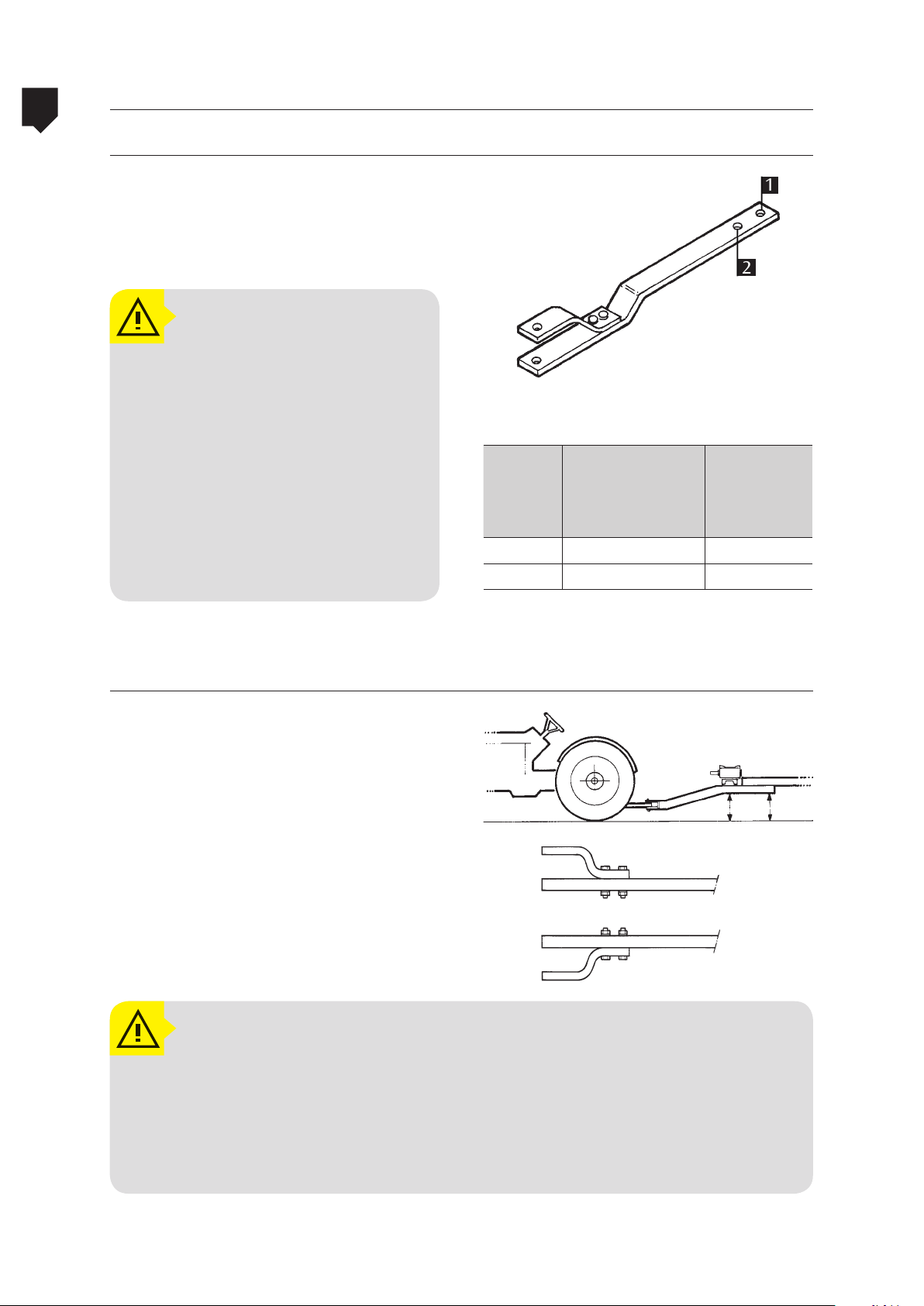
Insert the fork’s pin into the appropriate
hole (1 or 2) to vary the distance between
the power takeoff shaft and the connection
point (figure A).
ATTENTION!
The tolerances indicated on the
table (maximum load on the
traction bar in relation to the
distance between the power
takeoff point and the attachment hole on the traction bar)
were obtained from a tractor
with the power of 63 HP.
For further clarification, please
consult your tractor manual.
1
2
Table 2: Distance between the power takeoff shaft
and the connection point
Distance between
Holes
1 13.77 in 1003 lb
2 9.84 in 1300 lb
the power takeoff
shaft and the
connection point
Maximum
(static)
vertical load
Machine height and traction bar adjustment
Place the traction bar of the tractor in position so that after it has been attached the
machine will work leveled (figure B).
Flip over the traction bar to vary the height of
the attachment point (figure C).
ATTENTION!
Para saber o valor aproximado da carga exercida sobre a barra de tração dos tratores acoplados com as máquinas da linha ADVANCE 2000, basta somar o peso da
máquina com a capacidade do tanque. O valor obtido deve ser multiplicado por
0,12 e o resultado encontrado é o valor aproximado em kg depositado na barra
de tração do trator.
A
A
A = A
2-30
Page 31

ADVANCE 2000
With the traction bar in the chosen position
(please see the traction bar adjustment), start
the coupling procedure as described below.
• Corte as cintas plásticas utilizadas para
fixar o garfo do engate.
2
ASSEMBLY
A
B
• Posicione o garfo do engate na horizontal e coloque o pino de engate no
o lateral.
fur
• Position the eye type hitch between the
traction bar of the tractor as is shown in
the figure.
• Insert the hitching pin through the traction bar and through the hitch.
• Insert the safety pin to lock the hitching
pin in place.
• Thread the safety chain through.
C
• Allow some slack in the chain so as to
allow the tractor to maneuver without
stretching it.
2-31
Page 32
2
ADVANCE 2000Acoplamento
Assembly and adjustment of the conventional power takeoff shaft
NOTE:
ASSEMBLY
Before using the equipment for
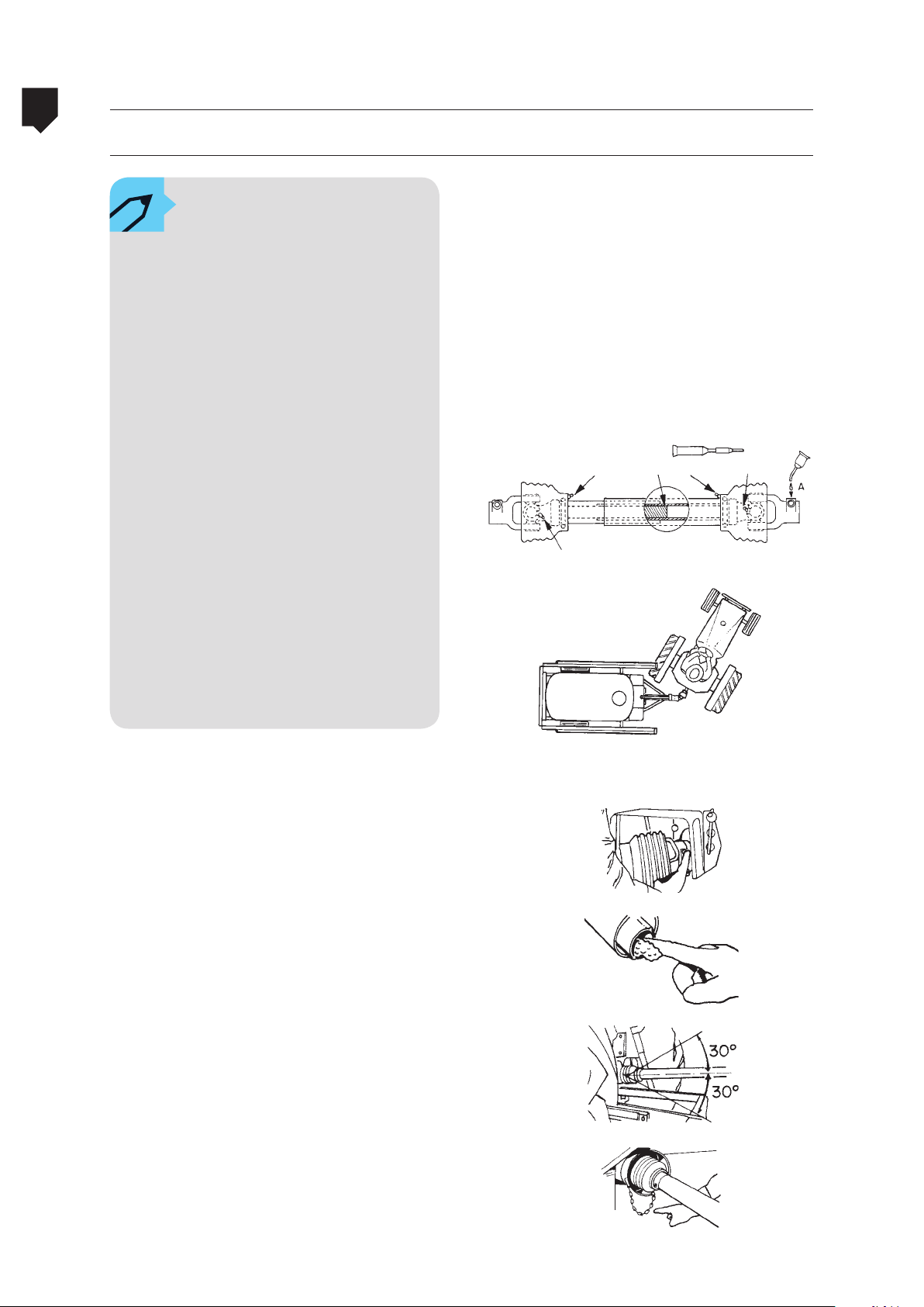
the first time, clean and lubrica-te all the PTO shaft points
with grease NLGI-2 lithium based as shown in the illustration
be-side (for further information on recommended grease,
refer to the lubrication table).
Only operate the power takeoff
shaft fitted with its protection
cover. The chain must be re-
-placed if one or more links are
stretched.
This procedure must be carried
out with the machine stopped
and the engine off. Employees
performing any kind of mainte-
-nance service in the PTO shaft
must wear adequate PPE such
as protective gloves, boosts,
glasses, etc.
2-32
• Install the PTO shaft on the IPTO (independent power take off) and install the safety
chain. Angular movements should be considered when assembling the chain.
• Adjust the length by cutting the boom and
the protection proportionally. Be sure to remove and clean all burrs.
• Acople o cardã e instale a corrente de segurança. Na montagem da corrente devem
ser considerados os movimentos angulares.
• Shut-off the PTO in excessively closed
maneuvers.
Page 33
ADVANCE 2000 Controller mounting
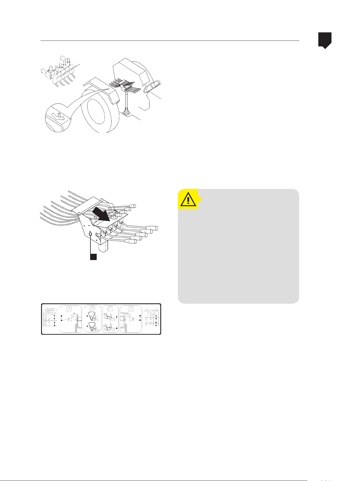
• Mount the hydraulic control support to
the tractor in a convenient position.
• Place the actuation control unit (A) on
the hydraulic control support.
sticker
ATTENTION!
2
ASSEMBLY
A
STICKER
Indicating the hydraulic system is working (for machi-
-nes with cable-operated control)
After installed, the hydraulic
and spray circuit controls levers
will be positioned close to the
operator for easy operation. As
the operator may be in front
of or even beside the control
levers, this requires the use of
original pin with cotter pin and
safety chain properly installed
to avoid accidents.
2-33
Page 34
2
ASSEMBLY
Assembling the controllers
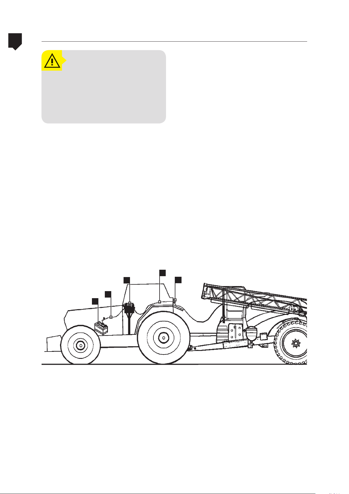
ATTENTION!
The electrical cables and looms
were designed and manufactured to be installed in the locations as described in the instructions below.
ADVANCE 2000
• The red colored cable must be connected
to the battery’s positive (+) pole and the
black cable must be connected to the battery’s negative (-) pole.
Fasten the controller to the support and
•
connect the cable to it (the cable connection on the controller is done by means of
male/female connector
s (D).
• Attach the controller’s support (A) to the
cabin floor or to the tractors mudguards
in case it does not have a cabin; on tractors with cabins the looms must be passed
ough the points designed for said pur-
thr
pose on the cabin. To install the controller
pr
oceed in the following manner:
• Thread the loom from the battery (B)
through its correct point on the tractor’s
cabin leaving the connector (which will
be connected to the controller) inside it,
and the other end of the cable must be
installed on the tractor’s battery (C).
E
A
B
C
• Feed the loom with the female socket
through the correct point on the tractor’s cabin. The female socket must be
attached together with its support to the
outside of the cabin (or to the rear of the
tractor), and the other end with a connector must be connected to the controller.
After hitching the equipment to the trac-
•
tor take the male socket that is attached
to the side of the belts fairing and connect it into the female socket located on
the back of the tractor.
D
2-34
Page 35

ADVANCE 2000 Assembling the controllers
ATTENTION!
Before unhitching the equipment, power off the controller
by means of the “ON/OFF” switch and disconnect the male /
female socket. If the controller
remains powered on then there
will be consumption of power
from the battery, and may even
totally drain it.
2
ASSEMBLY
2-35
Page 36

2
ADVANCE 2000Assembling the booms
• Install the booms supporting crossbeam.
ASSEMBLY
• Install the booms supporting springs.
OBSERVATION:
Install the washers as shown in
the picture.
• Install the booms (A) on the frame.
2-36
A
Page 37
ADVANCE 2000
Assembling the booms
2
• Install the cylinder on the boom.
ASSEMBLY
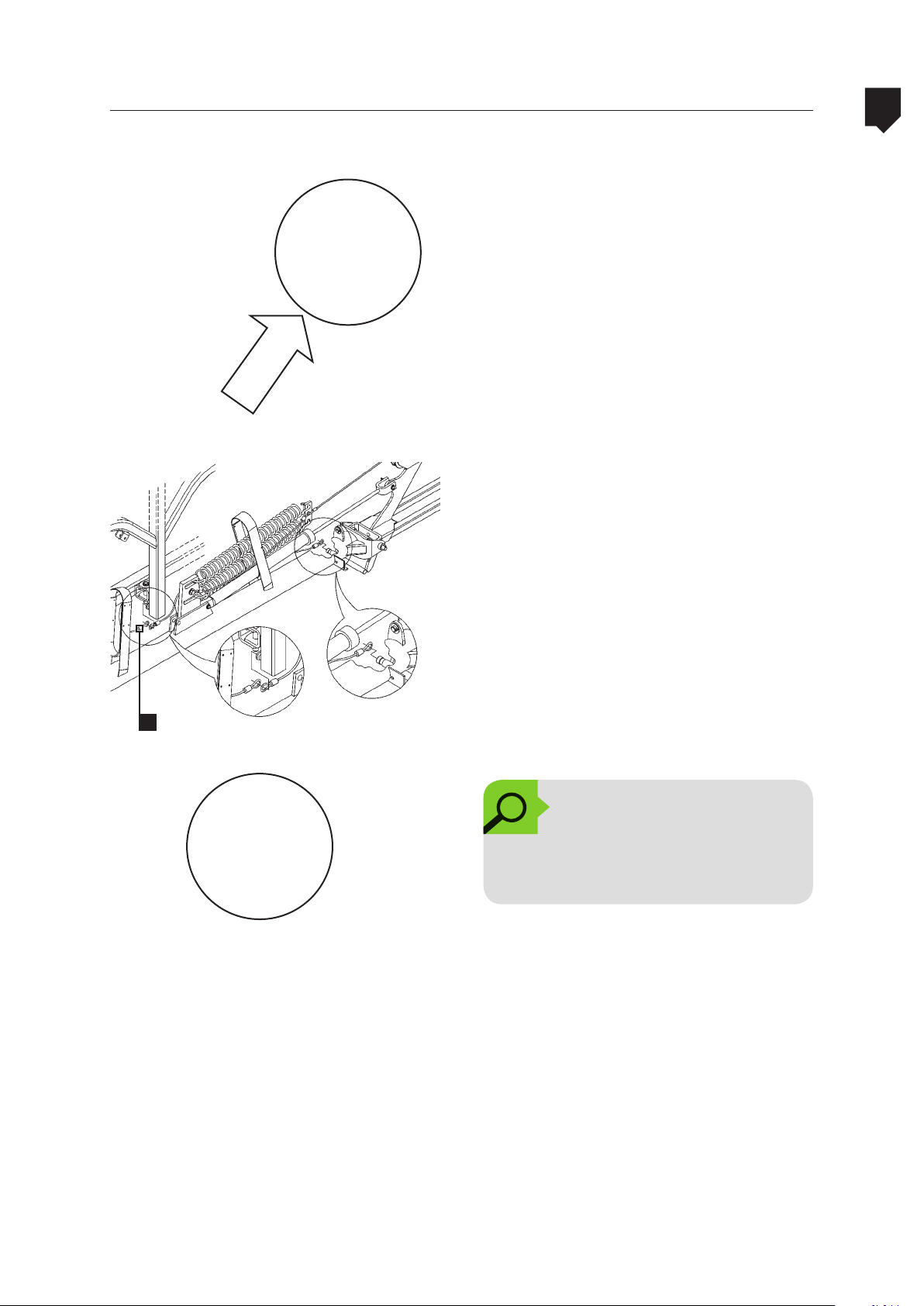
• Install the stabilization cables (B) on the
boom.
B
OBSERVATION:
Keep the clamps joining the
boom sections I and II.
2-37
Page 38

2
ASSEMBLY
Assembling the booms
• Install the safety cable.
• Install the central boom.
ADVANCE 2000
• Install the hoses.
OBSERVATION!
The hoses have different sizes.
The shorter one must be installed
on the 1st in-line filter and the
longer one on 2nd in-line filter.
2
1
1
2
2-38
Page 39

ADVANCE 2000
cylinder
fork
Assembling the booms
• Unfold and fold carefully the booms to
make sure that the hoses are not entangled on the structure.
2
ASSEMBLY
• In case of problem when folding the
booms, adjust the cylinder fork.
2-39
Page 40
2
Assembling the booms
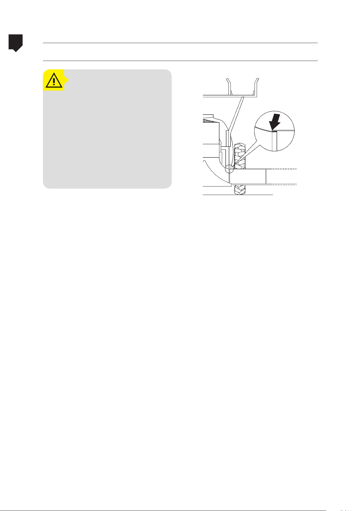
Fixing the air assistance canvas tube (Advance Vortex)
ATTENTION!
ADVANCE 2000
ASSEMBLY
Remove the boom when transporting the sprayer on trailers,
trucks or tows.
The boom lock system is designed for operations at low speeds.
Lock the boom when moving the
sprayer within the farm.
Only unfold or fold the boom in
areas free of obstacles such as
electricity supply cables, trees, etc.
air assistence
canvas tube joint
2-40
Page 41
ADVANCE 2000 Assembling the nozzles tubes and boom skid
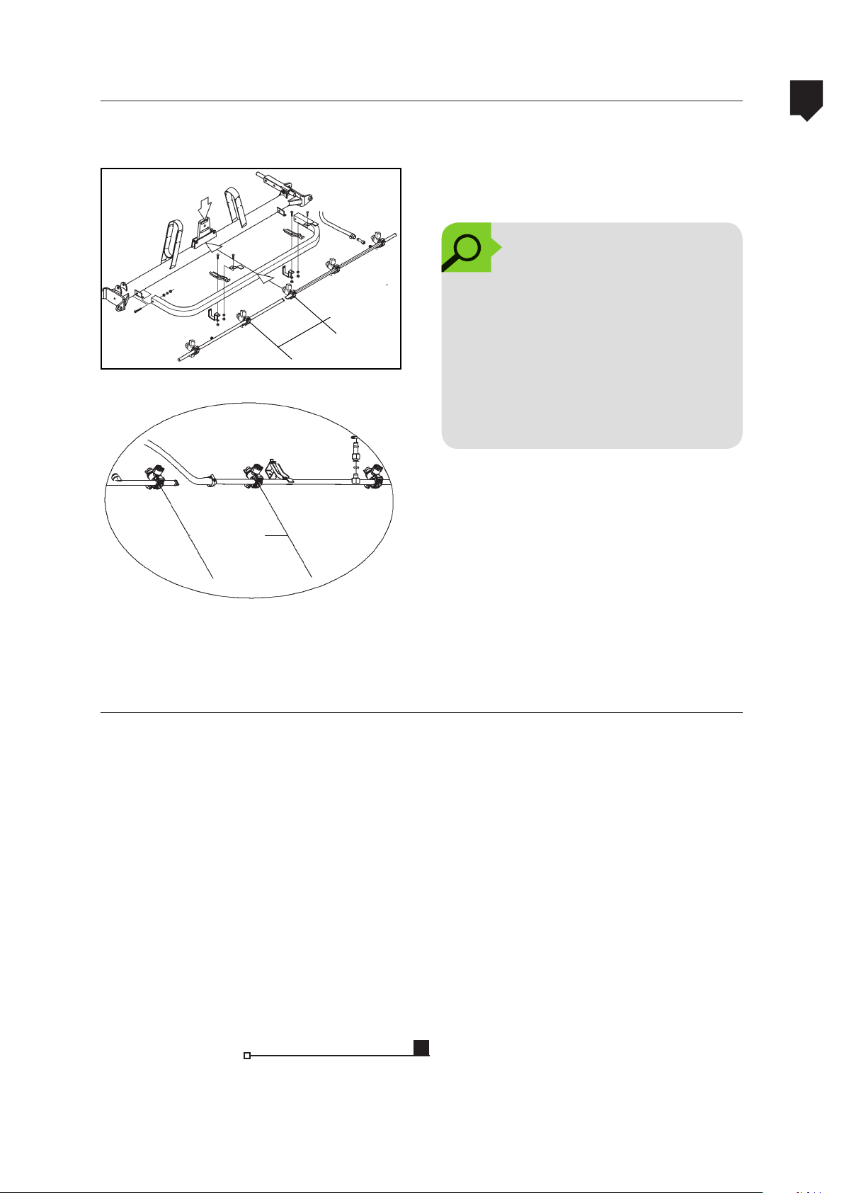
• Start to install the nozzle tubes on the
central boom.
OBSERVATION!
The central boom branch is di-
19.68 or
13.77 in
• Install the other part of the central branch
19.68 or
13.77 in
vided into two parts: the part
which has three nozzle-holders
must be assembled so that the
furthest nozzle-holder from the
chemical mixture inlet on the
branch is aligned with the sliding frame center.
keeping 19.68 ou 13.77 between the centers of the nozzle-holders. After that, install the branches of the other sections.
2
ASSEMBLY
Assembly the boom skid
• Feito isso, monte os ramais dos demais
segmentos.
• The position of the ot 19.68 ou 13.77 in.
between nozzles chosen at the time of
purchase.
• Mount the skids on the boom (A) between
the last two nozzle holders as shown, otherwise the boom assembly can be damaged.
A
2-41
Page 42
2
ASSEMBLY
Mounting the nozzles into the nozzle holders
Bijet
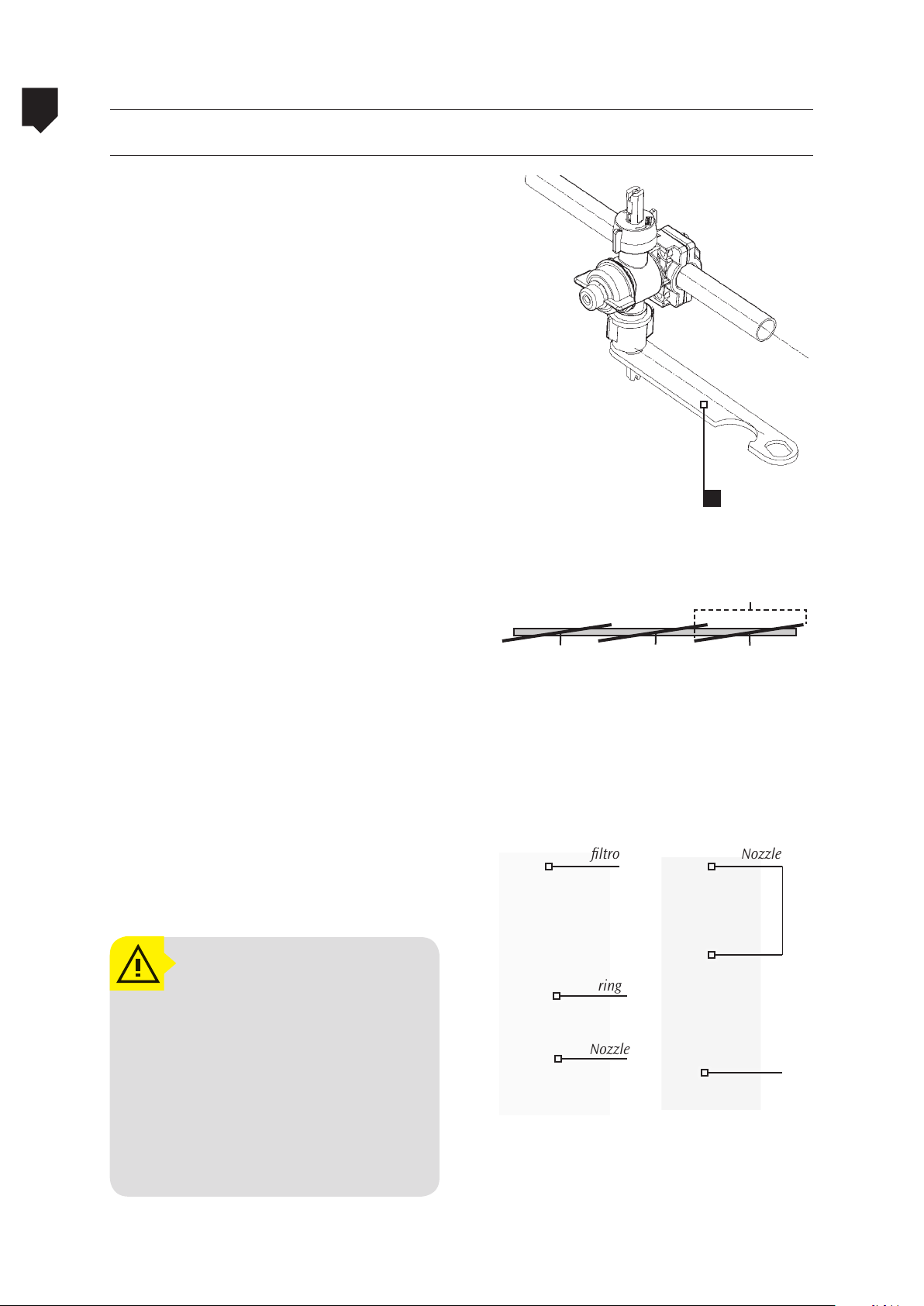
The bijet nozzle holder leaves the factory already mounted onto the spraying extensions.
Nevertheless, it will be necessary for you to
install the nozzles that you chose when purchasing the equipment. To install the nozzles
into the nozzle holders, proceed as follows:
• The conical nozzles can only be mounted
onto the threaded sleeves. Nevertheless,
the threaded sleeves may also accept the
fan type nozzles. Under this condition the
fan type nozzles must be aligned through
the use of the nozzle alignment spanner
which is found in the equipment accessory box. To do this proceed in the following manner:
ADVANCE 2000
A
1. Install the fan type nozzle unit into
the nozzle holder and tighten it by
hand onto the threaded sleeve.
2. Place the nozzle alignment spanner
onto the fan type nozzle and align it
to the extension.
3. With the spanner aligned, tighten
the nozzle threaded sleeve.
4. The fast connect sleeves were exclu-
sively developed to be used with the
fan type nozzles. Their design prevents the nozzles from being mounted in an incorrect manner.
ATTENTION!
To work with flat spray nozzles
(fan) it is necessary that they are
positioned at an angle of 4 to 6
in relation to the boom.
Remain alert as to the correct usage of the filters (mesh) for the
nozzles. Read up on the manufacturer technical literature.
Spray range
Nozzle Nozzle Nozzle
Nozzle construction
Fan type nozzle Cone type nozzle
ltro
ring
Nozzle
Nozzle
lter
2-42
Page 43

ADVANCE 2000 Mounting the nozzles into the nozzle holders
Quadrijet (optional)
The Quadrijet nozzle holder is an optional
ATTENTION!
The fan nozzle is attached to
the unit by means of the fast
connect sleeve for greater practicality during eventual maintenance. The fact that the nozzle
sleeve is of the fast connect
type limits its usage as far as
pressure is concerned to a maximum of 100 PSI.
item. Upon request on the purchase of the
equipment, it will leave the factory with
these installed on the spray extensions.
The mounting of the nozzles onto this
holder is not different from that of the Bijet nozzle holder.
These nozzle holders guarantee greater versatility during use, since the operator may
choose from the four nozzles what best serves
their purposes at the time of application.
2
ASSEMBLY
2-43
Page 44

Page 45

ADVANCE 2000 Table of contents
Presentation - Advance 2000 AM-18 ................................... 3-47
Technical specifications Advance 2000 AM-18 ..................... 3-48
Presentation - Advance 2000 Vortex .................................. 3-49
Technical specifications Advance 2000 Vortex ..................... 3-50
Options table ................................................................... 3-51
3
TECHNICAL SPECIFICATION
3-45
Page 46

Page 47

ADVANCE 2000 Presentation - Advance 2000 AM-18
8 1 2 3
5
6
3
TECHNICAL SPECIFICATION
7
1. Main reservoir
2. Booms
3. Frame
4. Chemical container rinse
5. Masterflow control
10 4
9
6. Power Takeoff Shaft
7. Jack
8. Clean water reservoir
9. Hand washing reservoir
10. Stair
3-47
Page 48

3
TECHNICAL SPECIFICATION
ADVANCE 2000Technical specifications Advance 2000 AM-18
Table 3: Technical specifications Advance 2000 AM-18
Weight
Empty machine weight 4034 lb
Dimensions
Total length 216.92 in
Width 124.01 in
Maximum height 139.36 in
Track (with 11,2 x 28 tires) 70.86 at 94.48 in
Free space from the ground (with 11,2 x 28 tires) 25.98 in
Application height 13.38 at 52.36 in
Booms
Total length 708.65 in
Nozzles
Nozzle holder with nondrip valve Bijet
Distance 19.68 in
Nozzle number 37
Tires
Tire 12.4 x 36
Pressure
Main reservoir
Material Polyethylene
Capacity 528.34 gallons
Auxiliary reservoir
Capacity Polyethylene
Material 52,83 gallons
Hand washing clean water tank
Material Polyethylene
Capacity 3.69 gallons
Hydraulic uid tank 1.16 gallons
Pump
Model JP-100
Filling rate
Power consumption 5,6 hp
Boom activation hydraulic pump
Flow rate 2.10 gallons /min.
Rotation 970 rpm at the PTO
Filter
Model FVS 200
Mesh 20/40
Line lters
Quantity 4
Agricultural chemical control
Model Masterow
Activation of the sectors Manual
Replenishment
Valve fast hitch valve
Clean source fast hitch valve
Agricultural chemical doser with container washer
Material Polypropylene
Capacity
Type of uid
Hydraulic uid ISO - VG 68
Recommended moving speeds
Working speed (maximum) 7.45 mph
Recommended moving speeds (maximum) 18.64 mph
Level marker Hose attached to the tank with markings
Stirring the solution Mechanical
36 PSI
26.41 gallons/min. at 540 rpm at the PTO
6.07 gallons
3-48
Page 49

ADVANCE 2000 Presentation - Advance 2000 Vortex
8 2 31
5
3
TECHNICAL SPECIFICATION
6
7
1. Main reservoir
2. Booms
3. Frame
4. Chemical container rinse
5. Masterflow control
9 10 11
6. Power Takeoff Shaft
7. Jack
8. Clean water reservoir
9. Hand washing reservoir
10. Stair
3-49
Page 50

3
3-50
TECHNICAL SPECIFICATION
Technical specifications Advance 2000 Vortex
Table 4: Technical specification Advance 2000 Vortex
Weight
Empty machine weight 4073 lb
Dimensions
Total length 224.80 in
Width 124.01 in
Maximum height 138.19 in
Track 70.86 at 94.48 in
Free space from the ground 25.98 in
Application height 13.38 at 52.36 in
Booms
Total length 708.65 in
Nozzles
Nozzle holder with nondrip valve Bijet
Distance 19.68 in
Nozzle number 37
Tires 12.4 x 36
Pressure 36 PSI
Main reservoir
Material Polyethylene
Capacity 792.51 gallons
Auxiliary reservoir
Material Polyethylene
Capacity 52,83 gallons
Hand washing clean water tank
Material Polyethylene
Capacity 3.69 gallons
Hydraulic uid tank 1.16 gallons
Pump
Model JP-100
Filling rate
Power consumption 5,6 hp
Boom activation hydraulic pump
Flow rate 2.10 gallons /min.
Rotation 970 rpm at the PTO
Filter
Model FVS 200
Mesh 24/40
Line lters
Quantity 4
Replenishment
Valve fast hitch valve
Clean source fast hitch valve
Agricultural chemical doser with container washer
Material Polypropylene
Capacity 6.07 gallons
Type of uid
Hydraulic uid ISO - VG 68
Ventilador
Rotação 2800 a 3000 rpm
Volume de ar 667 m
Velocidade do ar 62.16 mph
Consumo máximo de potência 25 cv
Recommended moving speeds
Working speed (maximum) 7.45 mph
Recommended moving speeds (maximum) 18.64 mph
Level marker
Stirring the solution Mechanical
26.41 gallons/min. at 540 rpm at the PTO
3
/min.
Hose attached to the tank with markings
ADVANCE 2000
Page 51

ADVANCE 2000
Table 5: options
Description Optional
Agricultural chemical controls
4 Way lever
4 Way cable •
4 Way electrical •
4 Way electrical with computer •
Hidraulic controls
Lever
Options table
3
Cable •
Electrical •
Pump
JP-100
JP-150 •
Tire
12,4 x36
16.9 x 30 •
Nozzle holder
Bijet
Quadrijet •
Distance
13.77 in, 52 nozzles •
19.68 in, 37 nozzles
Power takeoff shaft
Conventional
Wide-angle •
TECHNICAL SPECIFICATION
Clean source replenisher
Clean source replenisher •
Line marker
Line marker •
Items that are not marked with the “•” are standard items
3-51
Page 52

Page 53

ADVANCE 2000
Adjusting the track........................................................... 4-55
Filling the reservoirs ........................................................ 4-57
Instructions for triple washing........................................... 4-62
Drainage of the main tank ................................................. 4-64
Folding and unfolding the booms ........................................ 4-65
Calibrating the sprayer .................................................... 4-67
Calibrating the Masterflow spray control ............................ 4-69
Spray application technology ..............................................4-71
Table of contents
4
OPERATION AND ADJUSTMENTS
4-53
Page 54

Page 55
ADVANCE 2000 Adjusting the track
4
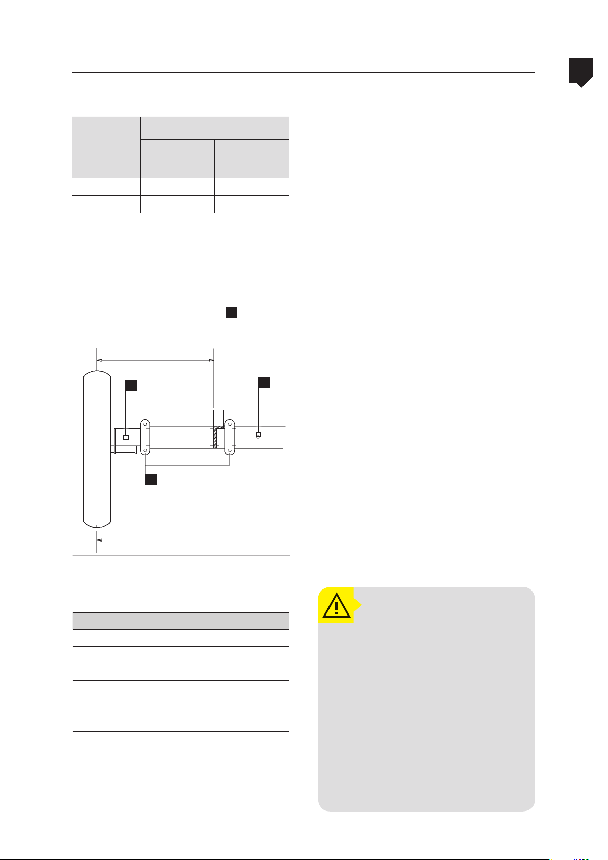
Table 6: track
Tires that
may be in-
stalled on the
equiment
12.4 x 36 70.86 88.58
9.5 x 42 70.86 88.58
minimum maximum
A
E
Track (in)
D
Before starting to open or close the track on
the ADVANCE 2000, drain the reservoirs so that
the equipment becomes lighter, facilitating
the operation; it is also recommended that the
equipment be completely washed down, as
well as the reservoirs, so that it diminishes the
risks of contamination of the mechanic who
will perform this operation.
The track must be chosen as a result of the
terrain topography. With the equipment clean and the reservoir drained, place it on a
flat location and follow with the procedures
given below:
OPERATION AND ADJUSTMENTS
1. Switch off the tractor’s engine and keep
the equipment hitched to the tractor. Place the hydraulic jack on the spot as marked by the sticker (D) on the chassis.
C
2. Raise the equipment on one side, sufficiently to raise the tire just off the ground.
F
B
Table 7: distance between the tire and the chassis.
A (in.) B (in.)
12.79 63
16.73 70.86
18.70 74.80
20.67 78.73
22.63 82.67
24.60 86.61
A - distance between the center of the tire and the external
face of the chassis.
B - Track
Loosen the bolts (C) on the half shaft
3.
mounting plate.
4. Set the half shaft to the desired track (E).
5. Tighten the bolts on the half shaft’s fastening plate (F).
6. Repeat this operation on the other side of
the equipment.
ATTENTION!
Before starting any work, make
a careful analysis of the terrain’s
topographic conditions and if necessary increase the track to prevent
any damage to the equipment.
This procedure must be carried
out by an experienced person
with the machine empty and
very well scotched on a leveled
ground. Do not allow people or
animals near the machine during
this procedure.
4-55
Page 56

4
ADVANCE 2000Track width adjusting
OPERATION AND ADJUSTMENTS
In farms with rugged topography, the semi-
-axis position can be changed, thus providing
greater equipment safety.
Going over terraces and other obstacles at
high speed must be avoided. We recommend
slowing the speed while going over them. It is
important to also remember that the machine speed when the tank is full must be slow
to avoid damaging the equipment.
We provide a table recommending the ideal
track width according to the terrain slope.
Table 8: Track width
Track width Declivity (maximum)
63 20%
70.86 22%
74.80 24%
78.73 25%
82.67 26%
86.61 27%
4-56
Page 57
ADVANCE 2000 Filling the reservoirs
Filling the main reservoir
4
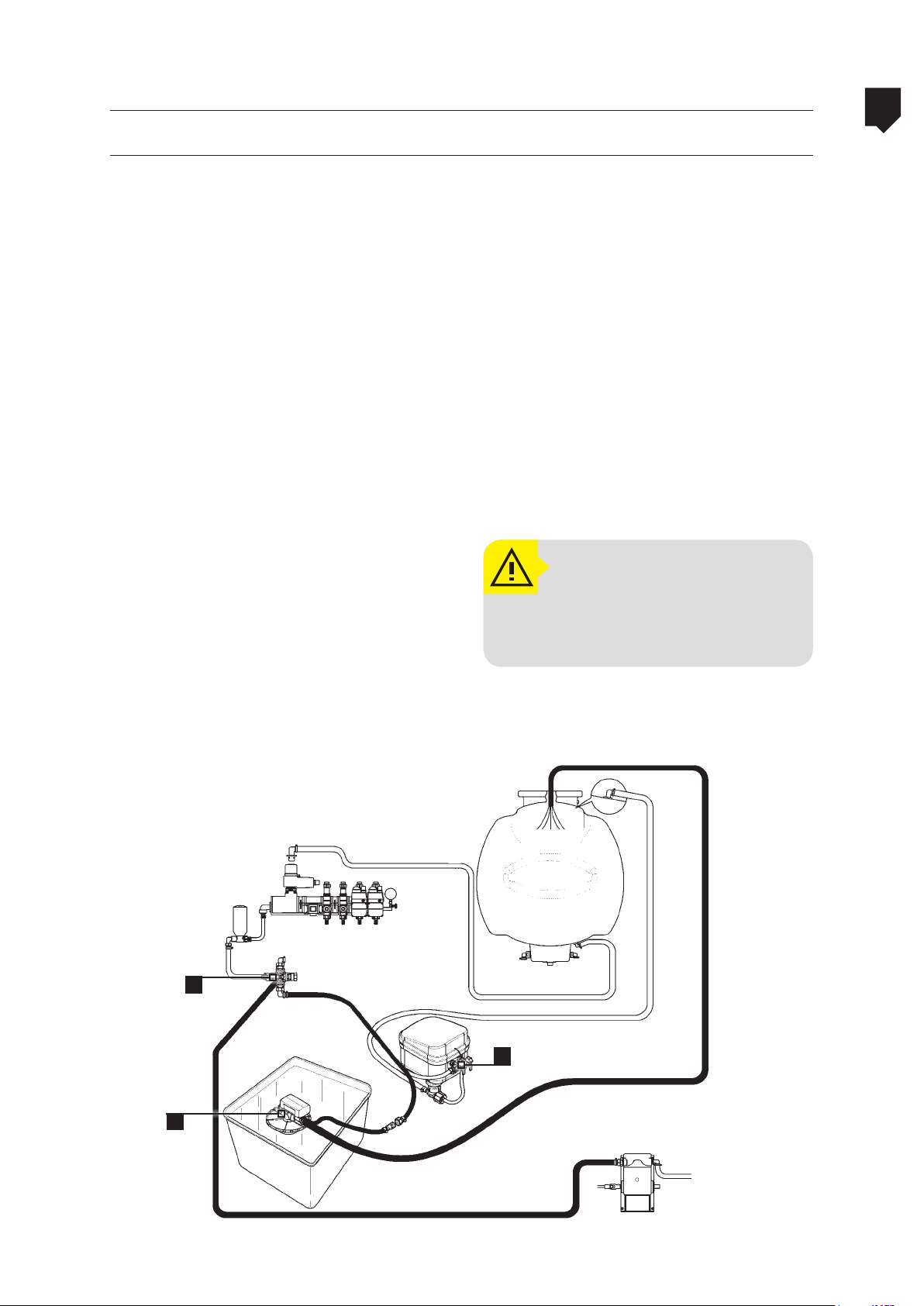
There are two ways of filling the sprayer’s
main reservoir:
1. Through the filler unit
• Put 50 liters of water in the spray tank.
• Open the cover of the main reservoir;
• Disconnect the intake hose from the
chemicals mixer valve (2).
• Connect the filler unit (3) hose to the
bypass valve (1) hose.
• Put the filler unit (3) in the water source
and the end of its discharge hose (4) at
the tank opening.
• Run the sprayer at 540 rpm at the PTO.
• Set the bypass valve (1) lever in the position of chemicals mixing.
After filling, set the by pass valve (1)
•
lever in the working position (pointed
to the control) and connect again the
chemicals mixer (2) hose.
ATTENTION!
When filling the reservoir, it is
recommended the use of IPE.
OPERATION AND ADJUSTMENTS
cover of the main reservoir
1
3
2
4-57
Page 58
4
ADVANCE 2000Filling the reservoirs
OPERATION AND ADJUSTMENTS
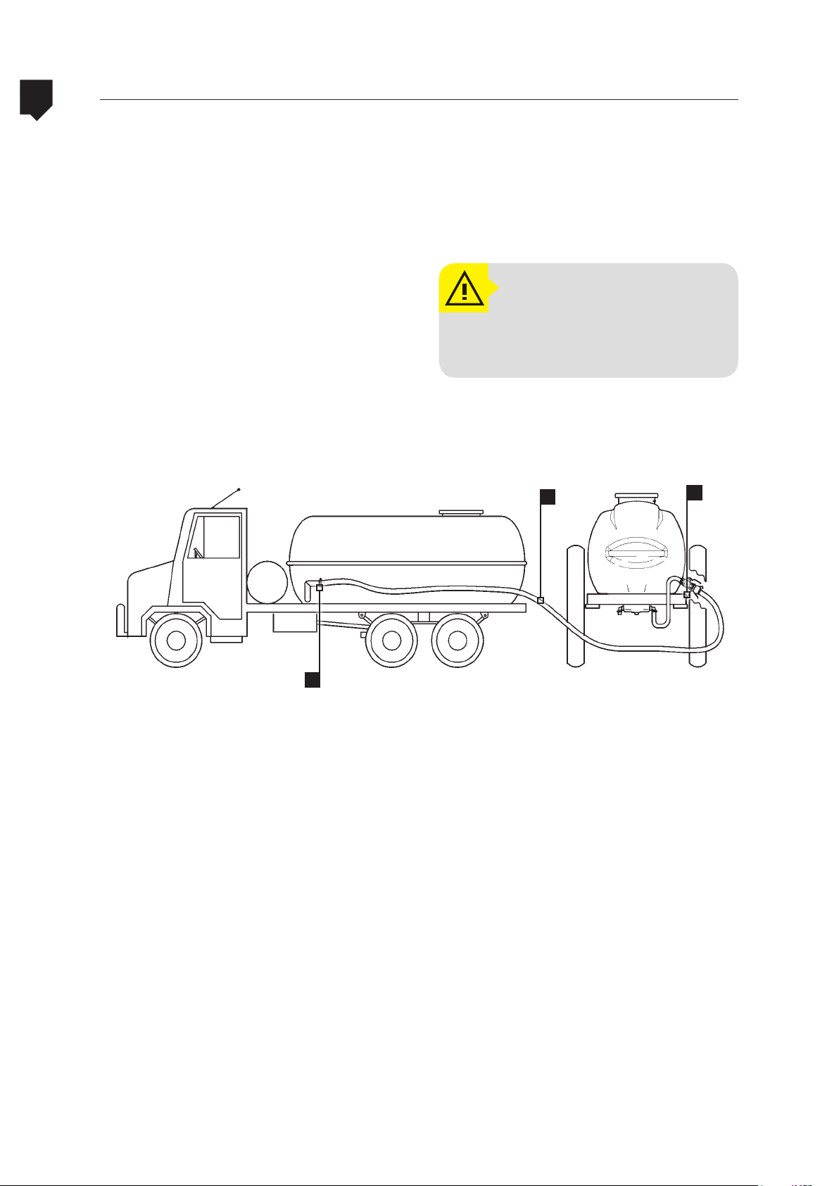
2ª. Through the quick fitting valve (optional)
• Connect the filling hose (2) with the quick
fitting valve (3).
• Start the tanker’s engine.
• Open the quick fitting valve (3).
• Open the filling hose valve (1). Watch the
water volume being transported to the
spray tank in order to prevent leaking.
• After filling the tank, close the quick fitting valve (3) and then the filling hose
valve (1).
• Disconnect the filling hose from the quick fitting valve.
ATTENTION!
When filling the reservoir, it is
recommended the use of IPE.
2
3
1
Detail of the quick ttiing valve (3)
4-58
Page 59
ADVANCE 2000
Filling the clean water tank
Filling the reservoirs
4
With the purpose of maintaining the sprayer
and discarding chemical containers with safety, the Advance 2000 has a 200 liters clean
water tank (A) that allows to clean the sprayer
chemical circuit and the chemical containers.
The chemical container rising occurs through
a rinse nozzle mounted inside the chemicals
mixer.
• To use the water from this tank, set the bypass
valve (D) turned to the clean water tank.
A
B C
D
• Engage the tractor’s PTO and keep the
chemicals control setting to turn on the
flow to the nozzles.
• Attention to this operation because the
tank will be drained in approximately 2
minutes and the lack of water in the pump
can cause damage to its components.
• Then set the bypass valve back, leaving it
turned to the main tank (C), since this is
the position used to spray.
ATTENTION!
The water from this tank is not
fit for drinking, or even washing
hands, faces, tools, etc. It must
be used only to clean the chemical circuit and to fill the chemical containers for the final rinse.
OPERATION AND ADJUSTMENTS
4-59
Page 60

4
OPERATION AND ADJUSTMENTS
Chemicals mixer
During this procedure, pay attention to the
amount of water that will be transported to
the main tank. Pay attention to the amount
of chemical product that will be placed in the
tank as the volume may increase significantly. Be careful with possible spills during this
procedure (WEAR PPE).
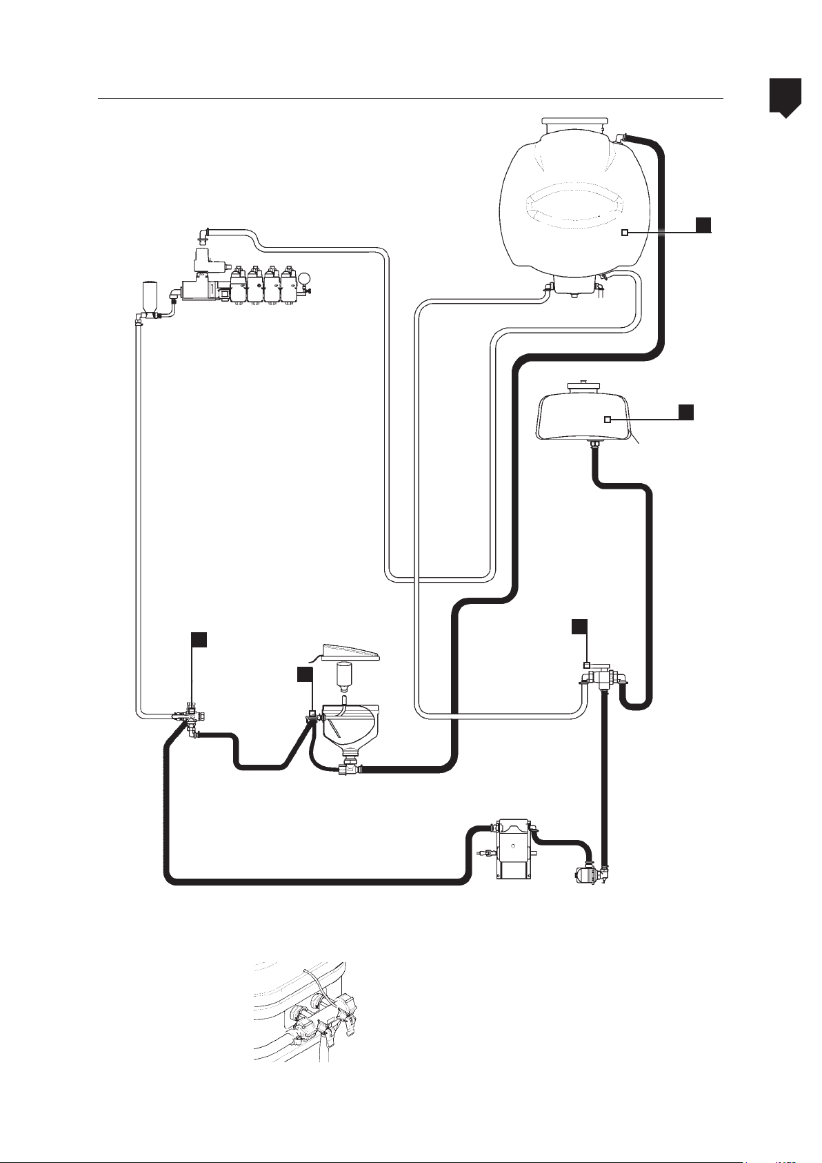
• Set the lever (1) in a position so as to
allow free water flow from the auxiliary
tank to the spray pump.
• Set the bypass valve (2) lever in the position “chemicals mixer”.
• Hold the chemical container over the
rinse nozzle and operate the chemicals
mixer (3) red lever for a few seconds (detail A). Then, operate the black lever to
wash inside the chemicals mixer
.
ADVANCE 2000
ATTENTION!
Operate the chemical mixer red
lever only after positioning the
chemical container over the
rinse nozzle.
This will keep you from being
wetted with water available for
washing inside the chemical mixer or even the chemical mixture
or water from the spray tank.
• Set the bypass valve (2) lever in the working
position (pointed to the spray control).
• Set the lever (1) in a position so as to
make the pump draw the mixture from
the spray tank.
• Watch out for sprinkling while rinsing
the containers. Use protective clothing.
4-60
Page 61
ADVANCE 2000 Chemicals mixer
5
4
4
1
2
3
OPERATION AND ADJUSTMENTS
Detail: Chemicals mixer valve
• Black lever: Chemicals mixer inside cleaning
• Red lever: Chemical container rinsing.
4-61
Page 62

4
ADVANCE 2000Instructions for triple washing
he containers that have been washed under
pressure with the solution and thereafter
with clean water for 30 seconds (container
of 10 liters) or for 60 seconds (with container
of 20 liters), it will not be necessary to triple
wash them. In case the clean water reservoir
has finished and after washing the container with the solution, it is then necessary to
TRIPLE WASH THE CONTAINER. To do this proceed in the following manner:
• Wear individual protection equipment –
IPE (gloves, apron, overalls, safety glasses,
hat, boots, masks).
OPERATION AND ADJUSTMENTS
• Fill the container with approximately 1/4
of clean water, replace the cap on the
container and tighten it sufficiently to
prevent any leakage whilst being shaken.
• Shake the container vigorously in all directions for approximately 30 seconds, to
remove any product residues from the internal walls of the container.
• Remove the container’s cap and carefully
pour out the water into the container washer.
• Repeat this operation twice more.
• Make the container unusable by puncturing the bottom of it with the aid of a
sharp instrument. Avoid damaging the
labels of the containers so that they can
be identified even after they have been
made unusable.
NOTE:
The unusable containers may be
temporarily stored at an appropriate and suitable location until they
e sent to their final destination.
ar
Flexible containers must be stored
and returned in specific containers
(e.g. bags) for this purpose.
4-62
Page 63

ADVANCE 2000
Additional information
Instructions for triple washing
1. In the case of medium or large sized containers (50, 100 and 200 liters), after having been washed with 1/4 of the volume,
eplace the cap on the container and roll
r
it on the ground for approximately 30 seconds.
2.
Complete the agitation by alternate-
ly raising the ends of the container and
supporting one end on the ground. This
operation must last for approximately 30
seconds.
3. Drain out the washing up water in the same
manner in which you used to drain the product and pour it into the sprayer tank.
4
OPERATION AND ADJUSTMENTS
4. This operation must be repeated twice
more. Make the container unusable at
the end of the TRIPLE WASHING.
Source: ANDEF – ASSOCIAÇÃO NACIONAL DE DEFESA
VEGETAL – (NATIONAL ASSOCIATION FOR THE PRESERVATION OF VEGETATION)
4-63
Page 64

4
OPERATION AND ADJUSTMENTS
ADVANCE 2000Drainage of the main tank
• After spraying, proceed to rinse inside
the tank.
• Spray the crop with the water of the
main tank.
• To drain the main tank, just pull the drain
valve rope located close (A) to the tank
filler opening. roll up the rope around
the support grooves so that the valve remains open until the complete emptying
of the main tank.
• After the total drain of water, unroll the
rope to close the valve again.
ATTENTION!
Do not empty t he sprayer tank
in places where it can contaminate the environment and poison man and animals.
The water used to clean inside
the main tank must be sprayed
on the crop. It must not be
drained in places where it can
contaminate the environment
and poison man and animals.
A
4-64
Page 65
ADVANCE 2000
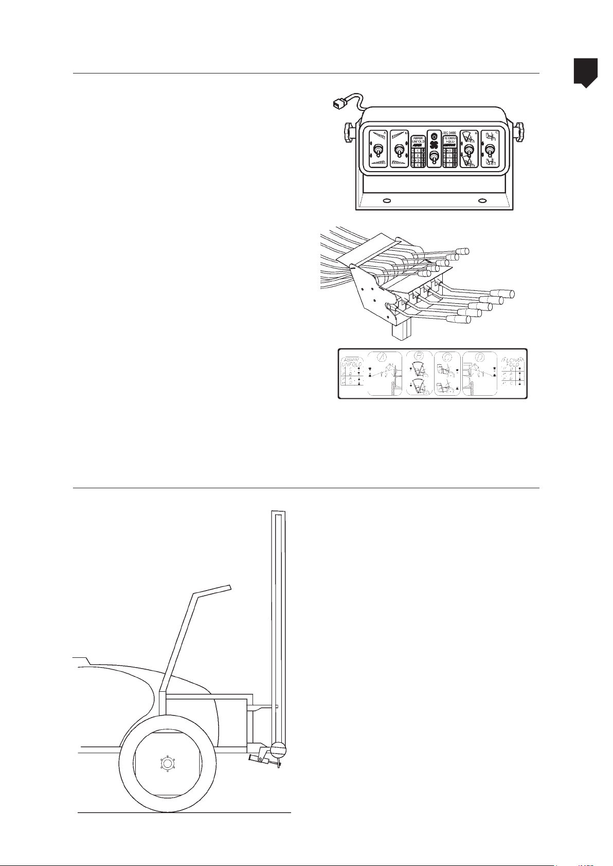
There are two ways to actuate the booms unfolding and folding:
• Through electric switches;
• Through cables.
Folding and unfolding the booms
4
OPERATION AND ADJUSTMENTS
Booms folding
Plate fixed on the control (with actuation
through cable) showing the sequence to unfold
and fold the booms.
• Set the booms in the vertical position
through the booms angular adjustment
cylinder.
4-65
Page 66
4
OPERATION AND ADJUSTMENTS
Folding and unfolding the booms
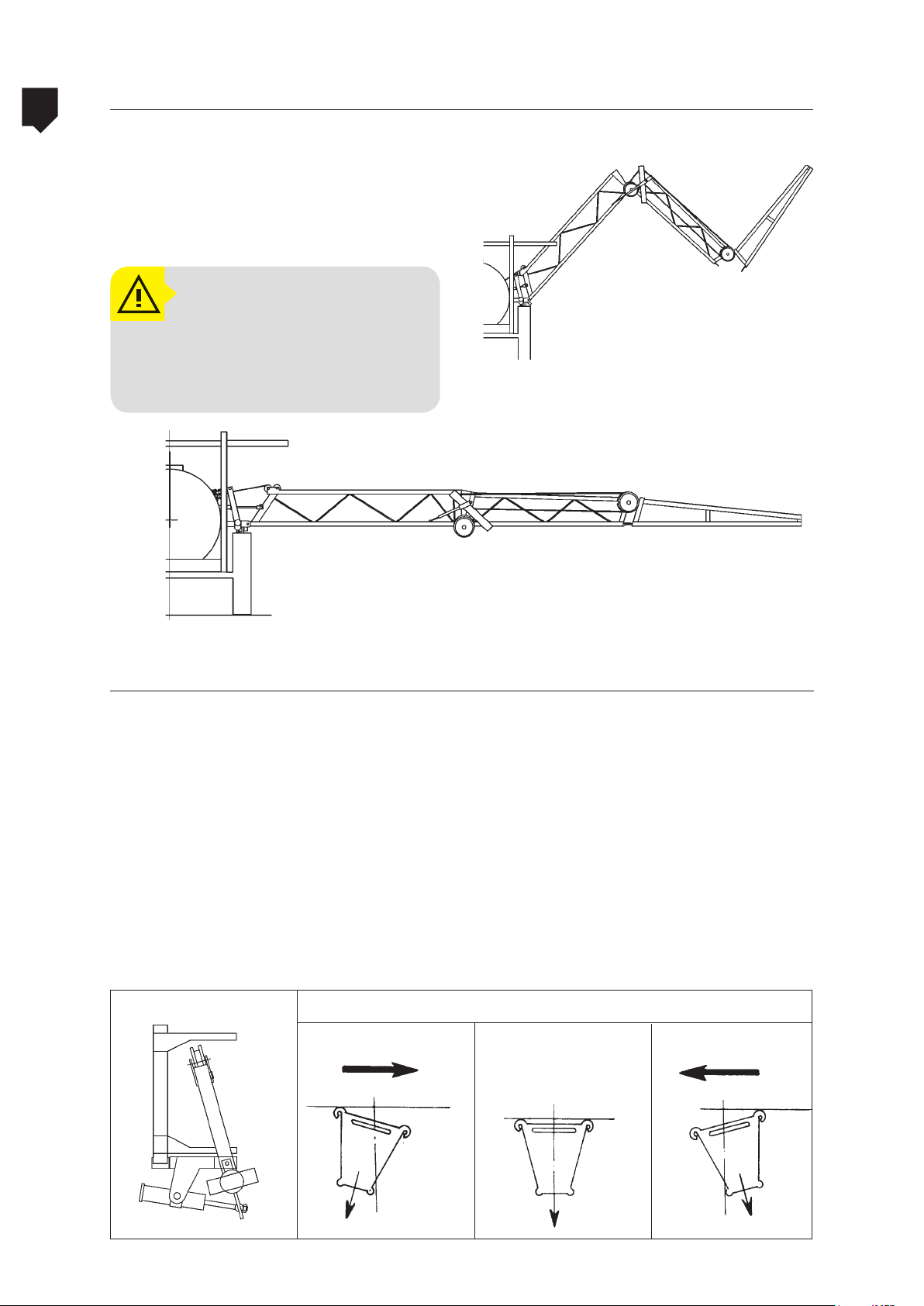
• Unfold the booms, both simultaneously
or individually.
• With the booms aligned (in the horizontal),
set them about 50 cm above the target.
ATTENTION!
Only unfold and fold the booms
in level areas away from trees
and electricity supply cables.
ADVANCE 2000
Booms position
• Through the hydraulic control, actu-
ate the booms angular adjustment
cylinder in order to set the booms
in a position so as to provide a good,
drift-free coverage.
• This part directs the air flow and
spray in a way so as to provide a
good coverage, even on pre-tillage
herbicides applications.
wind direction
The air flow channel must be adjusted in the
spraying site, taking into account the folowing factors:
• Treatment type (in pre- or post-emergence applications);
• Wind speed;
• Wind direction.
Channel settings
without wind
wind direction
4-66
Page 67

ADVANCE 2000 Calibrating the sprayer
4
Before calibrating the sprayer be sure:
• Suction filter is clean.
• Hoses are not twisted or bored.
• Pressure regulator components (valve seat,
valve and spring) are not worn or dirty.
Calculating the spraying volume
Ex.: Nozzle flow rate: 1,0 liter at 150 PSI² (JA
- 2 Nozzle)
Nozzle spacing : 0,5 m
Q =
Q =
gpm x 495
mph x f
0.21 x 495
3.72x1.64
( gpa )
( gpa )
• Pump is properly lubricated (oil level and
grease) and has no leakage.
• Nozzles are of the same model, not worn,
with correct flow rate and with clean
strainers.
After checking, proceed to calibrate as follows
Spraying volumes may be obtained using
the formula.
Where:
Q: Spraying volume (L/ha)
q: Nozzle flow rate (L/min)
f: Nozzle spacing (m)
v: Tractor speed (km/h)
495: Conversion unit
OPERATION AND ADJUSTMENTS
128.70
Q =
Spraying volume = 21.09 gpa
6.10
Calibrating the sprayer
2.10 gpa
1. Mark off 50 meters or 164.04 ft on the
ground to be sprayer.
2. Fill up the sprayer.
3. Choose the working gear.
4. Engage the PTO.
5.
Accelerate until reaching 540 rpm at the PTO.
6. Start moving at least 5 meters before the
initial mark.
7. Note the time it takes the tractor to move
50 meters or 164.04 ft.
4-67
Page 68

4
OPERATION AND ADJUSTMENTS
Calibrating the sprayer
8. On irregular ground, repeat this operation several times and take the average.
9. Stop the tractor with the acceleration
used to move the 50 meters or 164.04 ft,
open the nozzles and adjust the pressure
according to directions for the different
types of nozzles.
10. Use the calibrator bottle to collect the
nozzle spray volume during the same
time taken to move the 50 meters, and
read on the column corresponding to
the nozzle spacing.
11. Repeat this operation with several nozzles to obtain an average volume.
ADVANCE 2000
Figura A
12. The average obtained will be the spray
volume for the gear and pressure already determined.
NOTE:
To make this calibration valid, the operator must spray at the same speed used during calibration. When the electronic controller is in “automatic” mode, any displacement speed variation will be compensated by the controller.
Figure B
4-68
Page 69
ADVANCE 2000 Calibrating the Masterflow spray control
To calibrate the working pressure, proceed
P
A
as follows:
• Engage the PTO and accelerate gradually until reaching 540 rpm.
• Set the relief valve to the position P
(pressure);
• Turn the pressure regulator clockwise
to increase the pressure;
• Turn the pressure regulator counterclockwise to decrease the pressure.
Calibrating the booms
4
OPERATION AND ADJUSTMENTS
P
2 3 4 5
Run the sprayer and set all levers to turn on
the chemical flow.
• Set the lever (no. 1) to the position P
(pressure).
• Set the levers no. 2, 3, 4 and- 5 downward.
• Check the pressure registered on the pressure gauge.
• Choose one of the boom sections and
set to the side the corresponding lever to
turn off the chemical flow.
E
• Other levers must remain set downward
(open).
Check if there was uctuation in the pressure
registered on the pressure gauge. If so, proceed as follows:
NOTE:
The pressure must be the same
as indicated previously on the
pressure gauge, when this section nozzles are on.
• Loosen the fixing screw shown by the arrow (fig. E).
• Turn the grip clockwise to increase the
working pressure. Turn the grip counterclockwise to decrease the working pressure.
4-69
Page 70

4
OPERATION AND ADJUSTMENTS
ADVANCE 2000Calibrating the Masterflow spray control
• Once the boom section is calibrated, set
the lever downward (open).
• Repeat the same operation on the other
boom sections in order to keep constant
pressure along the entire boom, regardless of the number of boom sections on.
NOTE:
Do not change the engine rotation during the calibration. A
change in the rotation would
change the pressure on the nozzles and therefore their flow rate.
4-70
Page 71

ADVANCE 2000 Spray application technology
4
A successful spray application does not depend
only on a good sprayer or correct use of the
chemicals but also on factors to be determined
in the field under specialized orientation.
Among these factors, some concepts should
be part of a criterion of evaluation so that
positive results may be attained within the
pest control program.
Ideal time
The ideal time for spraying should be chosen
according to the chemical product characteristics, as well as to the field conditions:
• Infestation level of pests, diseases and
weeds;
• Ideal time;
• Application rate;
• Safety;
• Good coverage.
• Infection level of diseases;
OPERATION AND ADJUSTMENTS
• Growing stage of weeds;
• Weather conditions.
Safety
When spraying your crops, you must make
sure there will be no risk to people, animals
and environment. Avoid spraying at hotter
times, with humidity below 55% or under
windy conditions.
Correct application rate
Any type of application requires that the rate
be maintained during the whole spraying
work. This will be possible when you have a
good sprayer properly calibrated.
Good coverage
Do not allow the operator to handle chemicals and spraying machinery without the
proper individual protective clothing.
This calibration can be obtained through
practical methods or formulas. Please refer
to the section OPERATION AND ADJUSTMENTS
- CALIBRATING THE SPRAYER.
You have a good coverage when the whole
target is sprayed with uniform distribution,
with no risk to the environment and with
good results in the pest control.
The application rate does not have influence on the treatment results. Therefore
good coverages can be attained even with
different rates, which may vary according
to operational and regional factors.
4-71
Page 72

Page 73

ADVANCE 2000 Table of contents
General recommendations ..................................................5-75
Main filter and line filters .................................................5-76
Bijet nozzle holder ........................................................... 5-77
Quadrijet nozzle holder (optional) ........................................5-78
Oil level ...........................................................................5-79
Location of the lubricating points ...................................... 5-80
Lubrication (grease nipples) .............................................. 5-81
Lubricating and Oil changing procedures ............................. 5-82
Table of operations ......................................................... 5-83
5
MAINTENANCE
Lubricants and recommended filters ................................... 5-84
Power takeoff shaft ......................................................... 5-85
Belts tension ................................................................... 5-90
Mechanical agitator ......................................................... 5-90
Hydraulic control ............................................................. 5-91
Steel cables diagram ........................................................ 5-92
Winter storage ................................................................ 5-93
Trouble-shooting .............................................................. 5-94
Advance 2000 AM-18 - Circuit hydraulic ............................. 5-99
Advance 2000 VORTEX - Circuit hydraulic ...........................5-10 0
Changing the tires ............................................................5-101
Cleaning and storage ........................................................ 5-102
5-73
Page 74

Page 75

ADVANCE 2000
General recommendations
5
• After the first thirty hours of usage the
bolts, nuts and clamps, specially the nuts
on the wheels and axle fastening bolts
must be checked for tightness. If necessary, tighten them.
• Daily, after finishing the spraying, put clean water in the tank and run the machine
until all the water is drained. The disposal
of the residues must be spread over the
crops or around the edges of the crops;
• Clean the main filter and the line filters;
• Wash the machine internally and externally.
ATTENTION!
Never wash the sprayer or the individual protection equipment in rivers, lakes, streams, dams, etc. Non-compliance with these procedures may cause serious damage and
contaminate the environment.
These procedures will prevent problems during future applications, such as: blockage of
the nozzles, filters, etc, as well as protecting
its working life and equipment durability.
• Remove the individual protection equipment and wash it;
• Wash the working clothes separate from
the others;
• Take a bath using plenty of water and
soap and change your clothes.
MAINTENANCE
5-75
Page 76
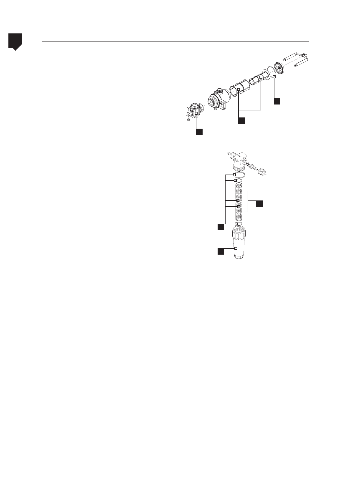
5
Main filter and line filters
The cleaning interval for the filters depends
on the quality of the water used as well as the
type of chemical product.
Clean the filters at every replenishment or
when necessary.
ADVANCE 2000
C
MAINTENANCE
The main filter and line filters are mounted
according to the illustrations below: (A) record, filter elements (B), rings (C), filter cover
(D), and nut housing (E).
A
C
D
C
E
5-76
Page 77
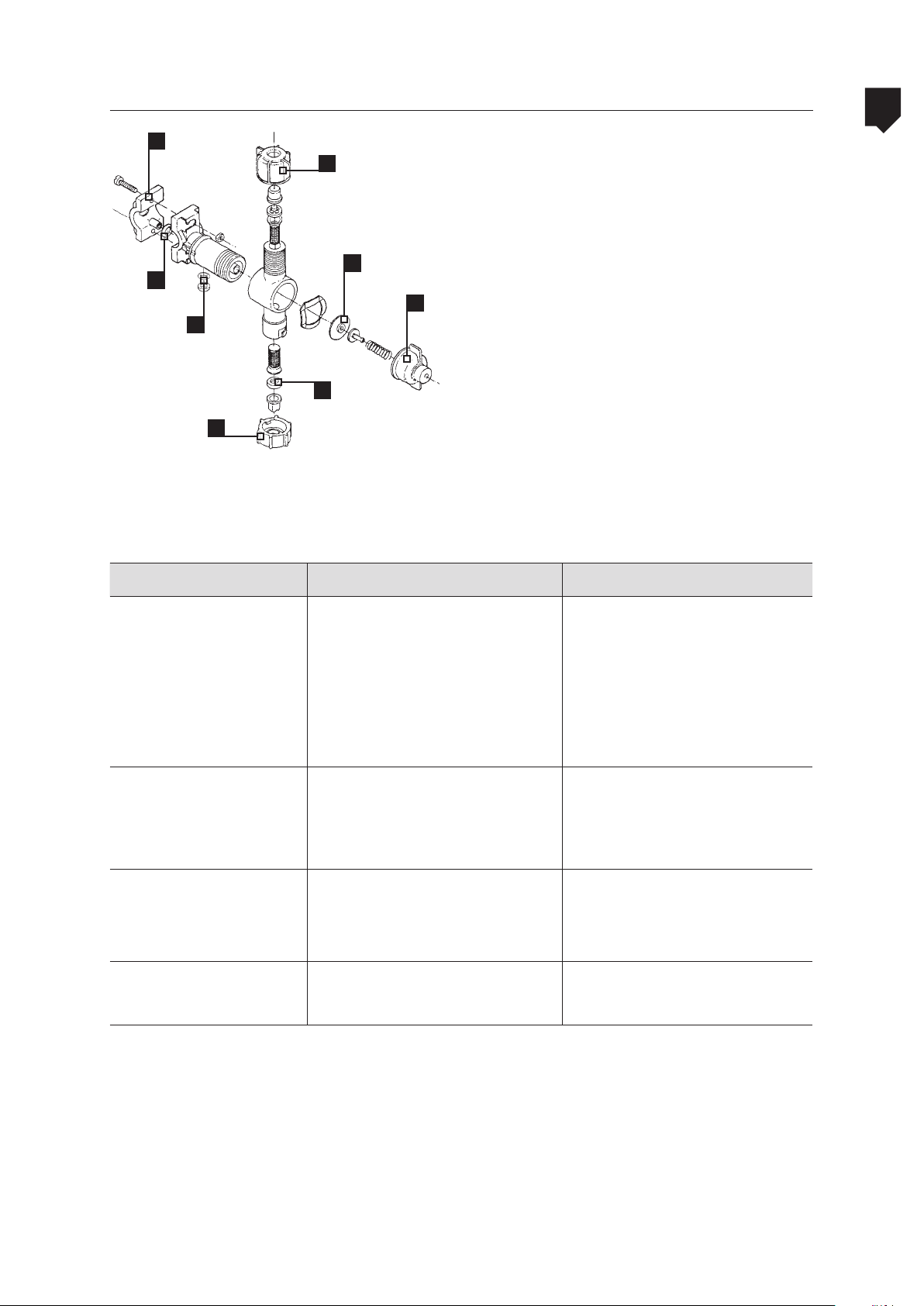
ADVANCE 2000
Bijet nozzle holder
5
4
5
7
3
1
2
6
5
Table 11: Problem, cause and correction - nondrip double nozzle holder
Problems Causes Correction
After the equipment has been used for an
extended period of time the need will arise
to do maintenance on the anti-drip valves on
the nozzle holders.
We present in the table below the problems
that may arise as well as the indications, the
causes and correction:
MAINTENANCE
Valve does not seal
Leakage between
the core and
nozzle holder
Leakage through the
connection with the
spray tube.
Leakage through the nozz-
le holder and the nozzle.
a. Nut (1) loose.
b. Impurities on the diaphragm.
c. Diaphragm rupture.
d. Diaphragm rupture with later
dumping of the product.
a. Lack of (2) seal.
b. (2) seal damaged.
c. Nut (1) loose.
a. Sealing ring (3) missing.
b. Sealing ring (3) damaged.
c. Nut (4) loose.
a. Nut (5) loose.
b. Filter (6) base damaged.
a. Tighten nut (1). Do not use
tools, only hand tight will do.
b. Remove and clean the dia-
phragm.
c. Replace the diaphragm.
d. Replace the diaphragm and
clean the plunger set.
a. Put in seal (2).
b. Replace seal (2).
c. Tighten nut (1) with your
hands.
a. Replace seal (3).
b. Replace sealing ring (3).
c. Tighten nut (4).
a. Tighten nozzle nut (5).
b. Replace lter (6).
5-77
Page 78

5
Quadrijet nozzle holder (optional)
ADVANCE 2000
After the equipment has been used for an
extended period of time the need will arise
to do maintenance on the anti-drip valves on
the nozzle holders.
We present in the table below the problems
MAINTENANCE
that may arise as well as the indications, the
causes and correction:
Table 12: Problem, cause and correction Quadrijet nondrip quadruple nozzle holder
Problem Cause Correction
a. Impurities on the diaphragm.
Valve
does
not seal.
b. Rupture of the diaphragm.
c. Rupture of the diaphragm fol-
lowed by chemicals buildup.
d. Nut (1) not tightened properly.
1
5
4
7
6
3
2
a. Remove and clean the diaphragm
b. Replace the diaphragm
c. Replace the diaphragm and
clean the plunger assembly
d.Tighten the nut (1).
Leakage between the
nozzle holder and the
body.
Leakage at the con-
nection with the pipe.
Leakage between the
nozzle holder and
the nozzle
(threaded sleeve).
Leakage between the
nozzle holder and the
nozzle.
a. Seal (2) missing.
b. Seal (2) damaged.
c. Nut (1) not tightened properly.
a. Packing ring (3) missing.
b. Packing ring (3) damaged.
c. Part (4) not tightened properly.
a. Nut (5) not tightened properly.
b. Base of lter (6) damaged.
a. Quick tting nut not tted properly.
b. Packing ring (7) damaged.
c. Base of lter (8) damaged.
a. Fit the seal (2).
b. Replace the seal (2).
c. Tighten the nut (1).
a.Fit the packing ring (3).
b. Replace the packing ring (3).
c. Tighten the bolts of the part (4).
a. Tighten the nut (5).
b. Replace the lter (6).
a. Fit the quick tting nut.
b. Replace the packing ring (7).
c. Replace the lter (8).
5-78
Page 79
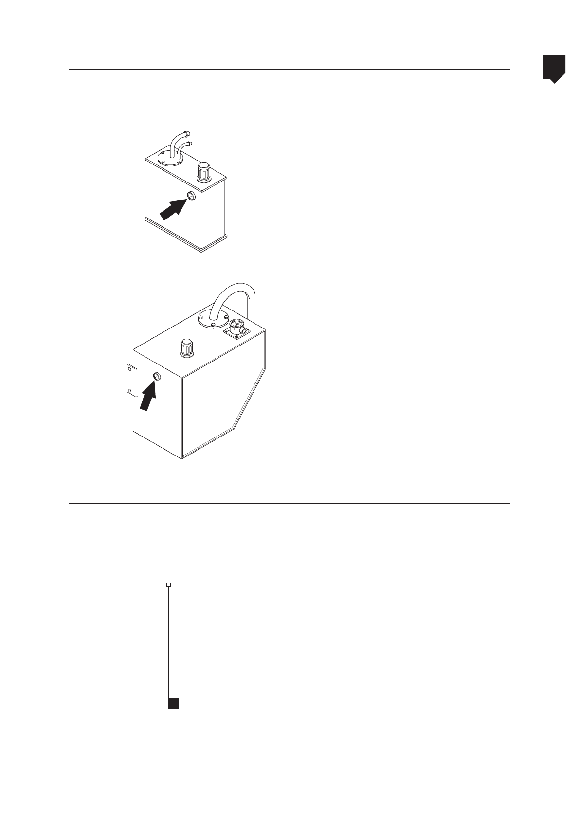
ADVANCE 2000
Hydraulic fluid level
Oil level
5
Hydraulic oil reservoir
ADVANCE-AM 18
hydraulic
fluid leve
Hydraulic oil reservoir
ADVANCE VORTEX
All of the hydraulic systems on this piece of
equipment share the same reservoir. To make
the best use of this system, some caution
must be taken during certain operations so
that the fluid does not become contaminated
and neither does the operation of hydraulic
components become prejudiced. Recommendations as to the use of hydraulic fluid:
• Only use hydraulic fluid that is recommended by the manufacturer;
• Do not mix fluids from different brands;
• Never pour lubricating oil for internal combustion engines into the hydraulic system;
• Do not operate the system if there’s a
shortage of the hydraulic fluid level in
the reservoir;
MAINTENANCE
hydraulic
fluid leve
Tank side support tube
• Take special caution so as not to contaminate the hydraulic fluid with water,
dirt or other fluids.
Check if the bolts of the tank side support
tube (A) are well tightened every 100 working hours. The recommended torque is 93.16
to 117.67 N
.m.
A
5-79
Page 80
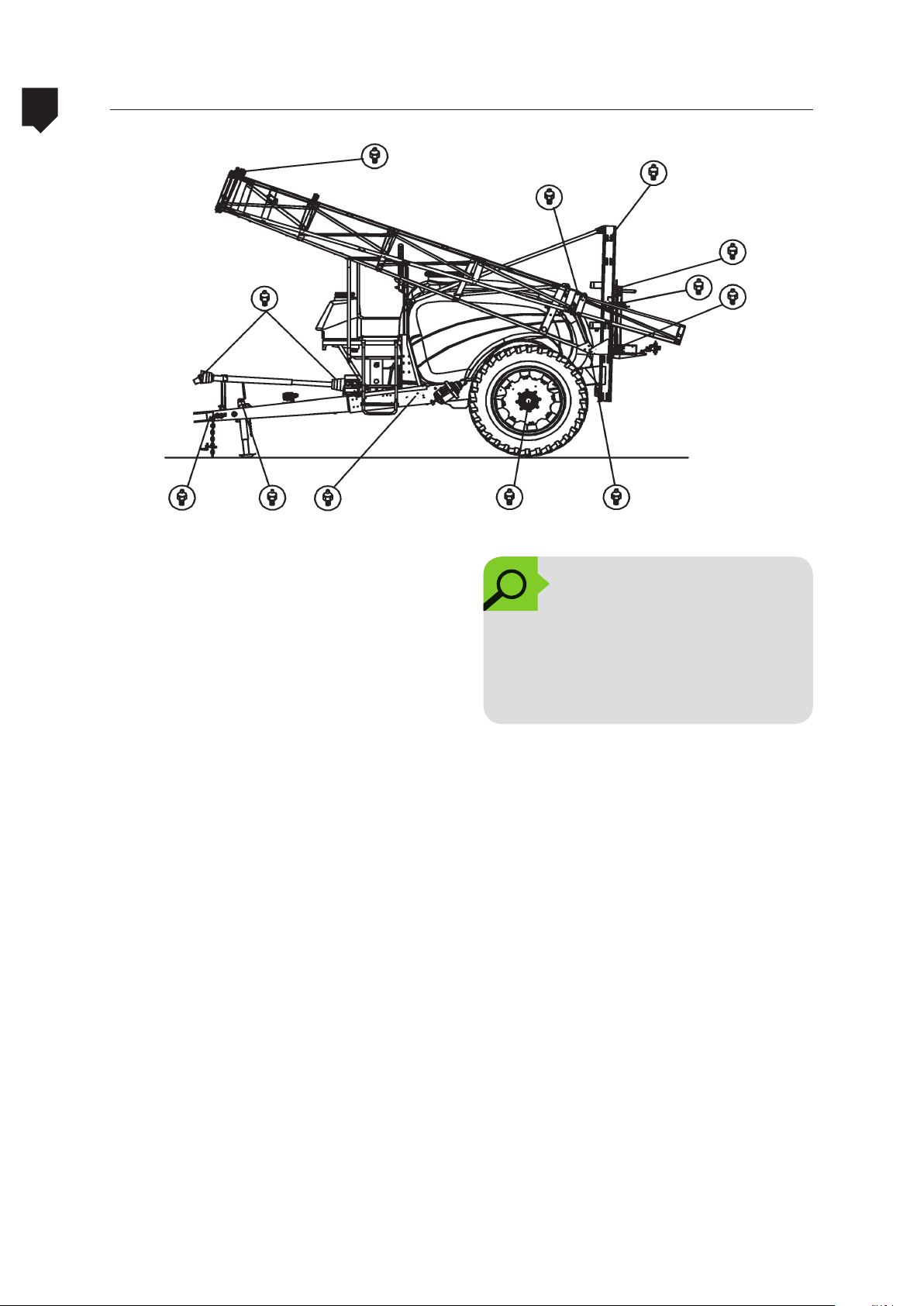
5
ADVANCE 2000Location of the lubricating points
MAINTENANCE
• Power Takeoff Shaft;
• Grease nipples for the booms and movable frame;
• Booms articulation;
• Traction bar;
• Wheel hub, etc.
OBSERVATION:
The lubrication interval for each
of the items below is described
in the “OPERATIONS TABLE” as
given in this chapter.
5-80
Page 81

ADVANCE 2000
Lubrication (grease nipples)
5
A
NOTE:
Just as with the oils it is recommended that greases from different brands are not mixed.
During the lubrication (greasing up), one
must take caution so that none of the grease
nipples are forgotten, as each one of them
has its importance in the system and are
marked with a lubrication point sticker (A).
Look at the components below for the lubricating points:
• Transmission unit, hitch, jack and wheels;
• Boom frame and support;
• Booms;
To lubricate these points make use of lithium
based grease NLGI-2.
MAINTENANCE
5-81
Page 82
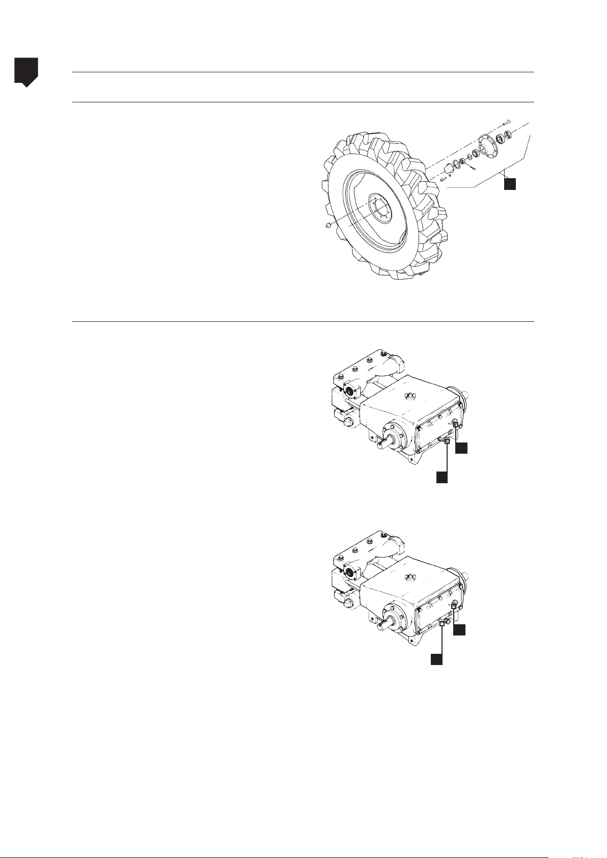
5
Lubricating and Oil changing procedures
Wheel hubs
Every 500 hours of service, remove the wheel
hubs (A) on the equipment, wash and examine the parts.
ADVANCE 2000
MAINTENANCE
A
Changing the lubricating oil in the agricultural chemical pump
In accordance with the information as laid
down in the operations table, the first oil
change for the pump must be carried out after the first 30 hours of work, whilst all the
following ones must be at 100 hour intervals.
To change the lubricating oil in the pump,
proceed:
• Remove the front fairing from the equipment.
B
JP-100
A
5-82
• Remove the drainage plug and let the lubricating oil drain fully.
• Replace the drainage plug (A) and tighten
it.
For the JP 100 / JP 150 pumps, proceed:
• Remove the bolt for the oil level as well as
the filler cap.
• Pour lubricating oil in until it starts to flow
out of the level.
• Reinstall the bolt in the oil level as well
as the filler cap with vent, immediately
thereafter tighten it.
• Replace the front fairing on the equipment and tighten the mounting bolts.
B
A
JP-150
Page 83

ADVANCE 2000
Table 11: Operations
Table of operations
Before using the equipment for the first time,
clean and lubricate all the PTO shaft points.
Check the belt condition and tension.
Check the hydraulic uid level (top up if
necessary).
Check for leaks around the stirrer’s mechan-
ical seal.
Check the tire pressure and adjust it if nec-
essary.
Check the oil level in the agricultural chemi-
cal pump.
Check, clean and wash the lter(s) in the
agricultural chemical circuit.
Wash the equipment externally.
Wash the spraying circuit components (main
lter and in-line lters).
Lubricate the lubrication spots.
Lubricate the articulation pins for the
booms and movable frame
Lubricate the universal joints on the PTO
shaft.
Check if mechanical agitator is working
properly.
Retighten the wheel nuts
Tighten the wheel bolts, the lateral support
shaft and the tank pipe.
Replace the oil in the agricultural chemical pump*.
Clean and inspect the pressure regulator’s
components.
Change the equipment’s belts.
Dismantle, check, wash the parts and lubri-
cate the wheel hubs.
Carry out the preventive maintenance on
the agricultural chemical pump.
Replace the machine’s hydraulic uid.
10 h or
daily
•
•
•
•
•
•
•
•
30h or
weekly
•
•
•
•
•
Periodicity
Every
100 h
•
•
Table of operations
Every
400 h
Every
500 h
Every
600 h
•
•
•
•
•
5
MAINTENANCE
5-83
Page 84

5
Lubricants and recommended filters
Caution to be taken with the hydraulic system
ADVANCE 2000
• Only use oil that is recommended by the
manufacturer (do not mix oils from different brands).
MAINTENANCE
• Never pour internal combustion engine
oil into the hydraulic system.
Table 12: Lubricants and recommended filters
Components Type Specication
Grease nipples,
PTO shafts and
wheel hubs
Hydraulic system
(tank)
Grease
Hydraulic fluid ISO-VG 68
Lithium based
• Take special caution so as not to contaminate the hydraulic fluid with water,
dirt or other fluids.
•
NLGI-2
Recommenda-
tion
Texaco - Multifak
EP 2
Texaco - Rando
HDZ 68
Amount
As required
1.16 gallons
20.60 gallons
(Vortex)
Pumps JP-150 /
JP-300
Filter
Element
All the oils for
Lubricating oil
Disposable
lter - - 01
URSA LA-3 SAE
15W-40 API CG-4
internal com-
bustion engines
under this speci-
cation
0.52 gallon
(JP-100)
5-84
Page 85
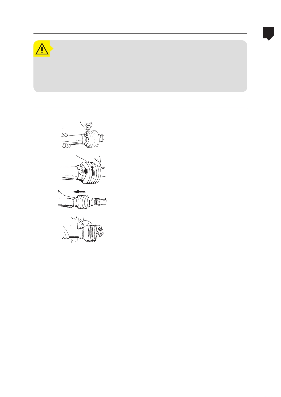
ADVANCE 2000
ATTENTION!
These operations must be carried out with the machine stopped and the tractor’s
motor switched off.
Any type of maintenance on the power takeoff shaft must be carried out with the
use of IPE, such as: Protective gloves, Boots, Glasses, etc.
Conventional PTO Shaft
Power takeoff shaft
5
MAINTENANCE
Disassembling:
1. Remove the lock screw.
2. Turn the guard cone until the indicated
position.
3. Pull the guard cone.
4. Remove the sliding ring.
5-85
Page 86
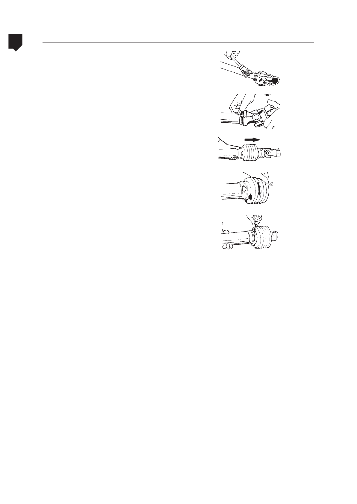
5
Conventional PTO Shaft
Assembling:
1. Clean and lubricate the male and female tubes.
ADVANCE 2000
MAINTENANCE
2. Install the sliding ring into the fitting with
the grooves pointing toward the tube.
3. Install the protection guards.
4. Turn the guard cone until the indicated
position.
5. Install the lock screw.
5-86
Page 87
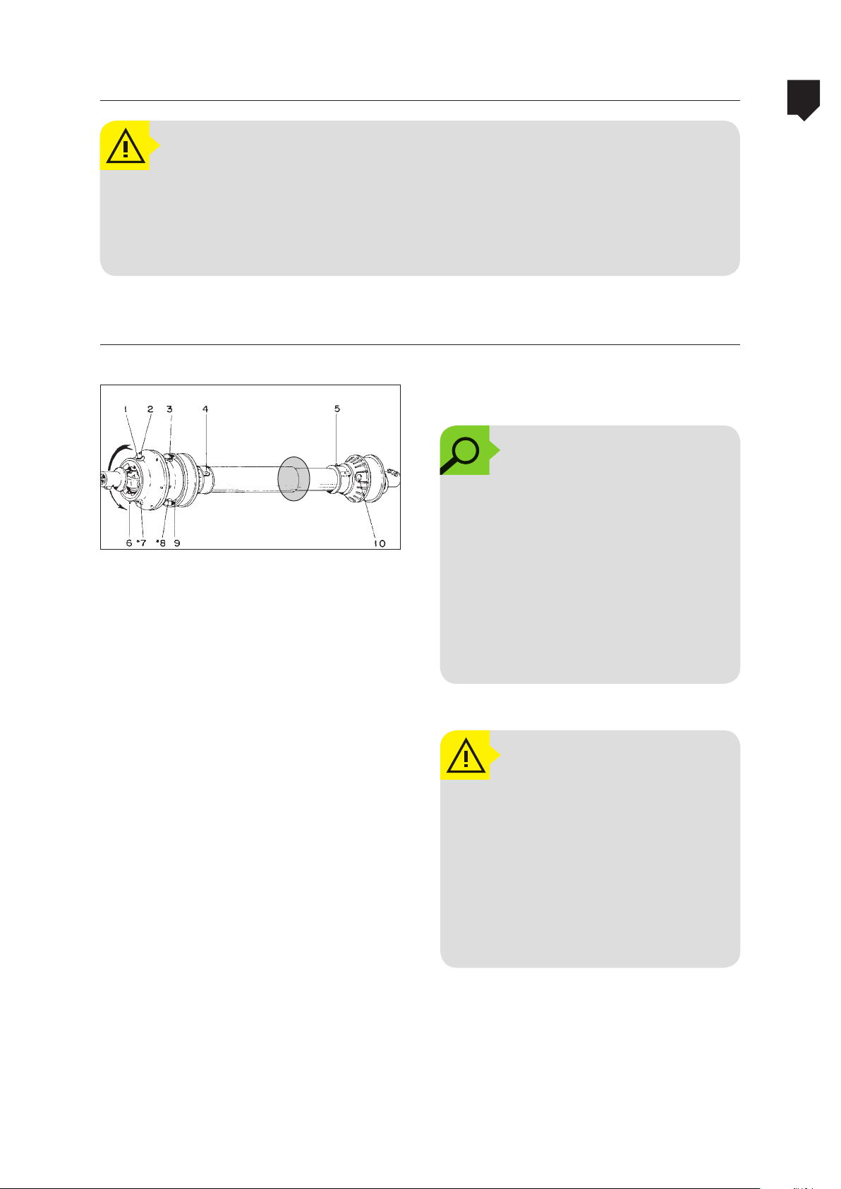
ADVANCE 2000 Conventional PTO Shaft
ATTENTION!
This procedure must be carried out by an experienced person with the machine
empty and very well scotched on a leveled ground. Do not allow people or animals
near the machine during this procedure. Operate equipment only with PTO shaft
equipped with safety protection (plastic covers).
Lubrication
Lubricate the points as indicated on the fig-
Correct position for lubrication
ure to the side every 8 hours.
OBSERVATION:
5
MAINTENANCE
A
All of the points as indicated on
the figure on the side must be
lubricated. Under no hypotheses must these lubrication
points remain without lubrication. Every 30 - 50 hours remove
the covers, clean and wash the
parts, lubricate and reassemble
the power takeoff shaft.
ATTENTION!
The lubrication of the power takeoff shaft (mounted) must be done
with the constant
joint in alignment with the male
/ female pipes. If it is done in any
other manner it will cause lubrication faults and consequently
damages to the component.
speed universal
5-87
Page 88
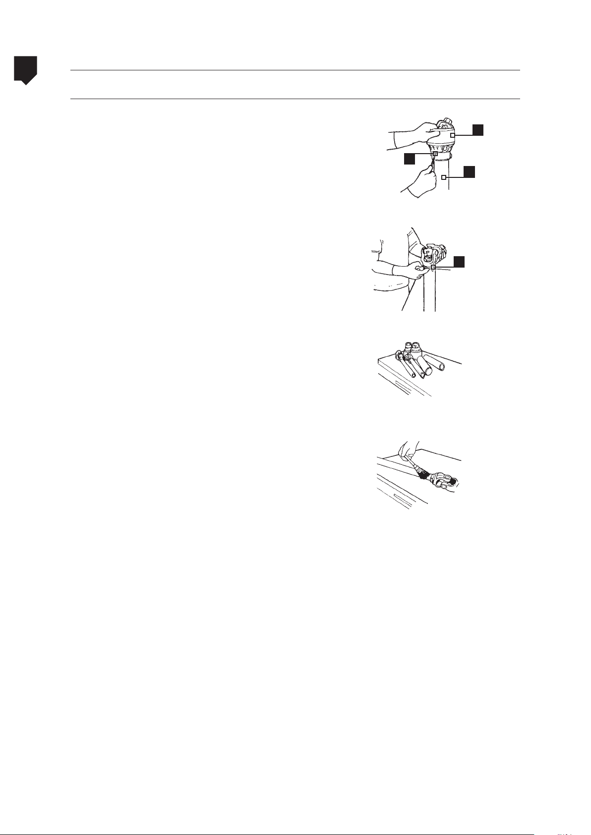
5
Power takeoff shaft
Disassembly of the power takeoff shaft for lubrication
ADVANCE 2000
With the power takeoff shaft in the position
as shown in fig. C, force the cover downwards
by simultaneously pressing locks 2 and 3 inwards with the aid of a punch or screw driver.
MAINTENANCE
With all 3 locks loosened, cover 1 will slide
over cover 3, which may then be removed.
Remove the circular lock 4 and separate cover 3 from the pipe.
Repeat the operations as indicated in figures
C and D on the side of the constant speed
universal joint and separate its components.
3
Figure C
Figure D
Figure E
1
2
4
Clean all of the parts with the aid of a brush,
using kerosene or Diesel and water and drying all of the parts thereafter.
Figure F
5-88
Page 89
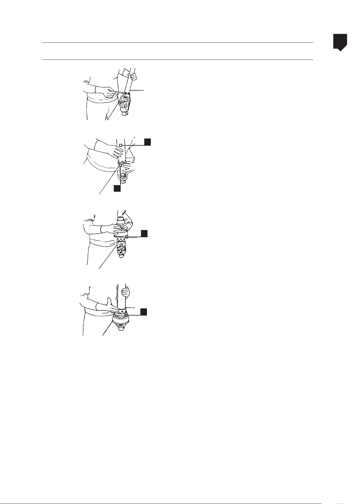
ADVANCE 2000
Assembly
Power takeoff shaft
5
Grease the groove for the c-clip - figure G.
MAINTENANCE
Figure G
3
Insert the cover 3 and attach it with a c-clip
4 -Figure H.
4
Figure H
Figure I
Figure J
With the power takeoff shaft in the position
1
4
as indicated by figure I, slide cover 1. Align
and cover 1 greaser with the existing nozzle
on the c-clip 4 - Figure J.
Force cover 3 downwards in such a manner
that it remains locked by means of the clips
2. Ensure yourself of the full locking of the 3
clips 2. If necessary force the clips together as
indicated in figure J.
Repeat the operation on the other side of the
power takeoff shaft and lubricate the entire
set, as indicated in figure A.
5-89
Page 90
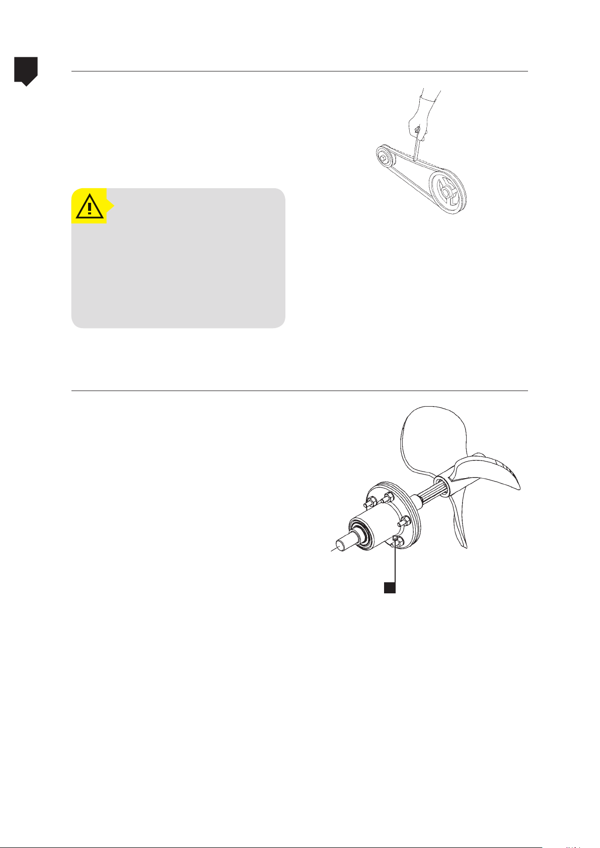
5
ADVANCE 2000Belts tension
• Check the belts tension periodically.
• Press the agitator belts as shown in the
figure beside. When pressed it should
slack 0.39 to 0.59 in. Do not use sharp-
-ended or cutting tool.
MAINTENANCE
ATTENTION!
Always stop the machine and
turn off the the tractor before
any and all kind of maintenance and use appropriate protective clothing, such as: gloves,
boots, goggles, etc.
Mechanical agitator
At any sign of the drain leak (A), replace
the mechanical seal.Contact your nearest
Jacto dealer.
A
5-90
Page 91

ADVANCE 2000
Cable adjustment
Hydraulic control
As the time goes by, it may be necessary to adjust the booms hydraulic actuation cables, if the
olding and folding operation is defective.
unf
5
To adjust proceed as follows:
• Loosen the nut (1).
• Loosen both bolts (2).
MAINTENANCE
ATTENTION!
Do not loosen these bolts all the
way, but enough to turn the adjusting rod.
• Turn the adjusting rod (3) clockwise or
221 3
counterclockwise, depending on the need
of adjustment.
NOTE:
This adjustment should be made
with the sprayer running, and
the cylinder that showed problem should be constantly actuated during the adjustment
so as not to tighten or loosen excessively the adjusting rod.
• Once the adjustment is made, retighten
the nut (1) and the bolts (2).
5-91
Page 92
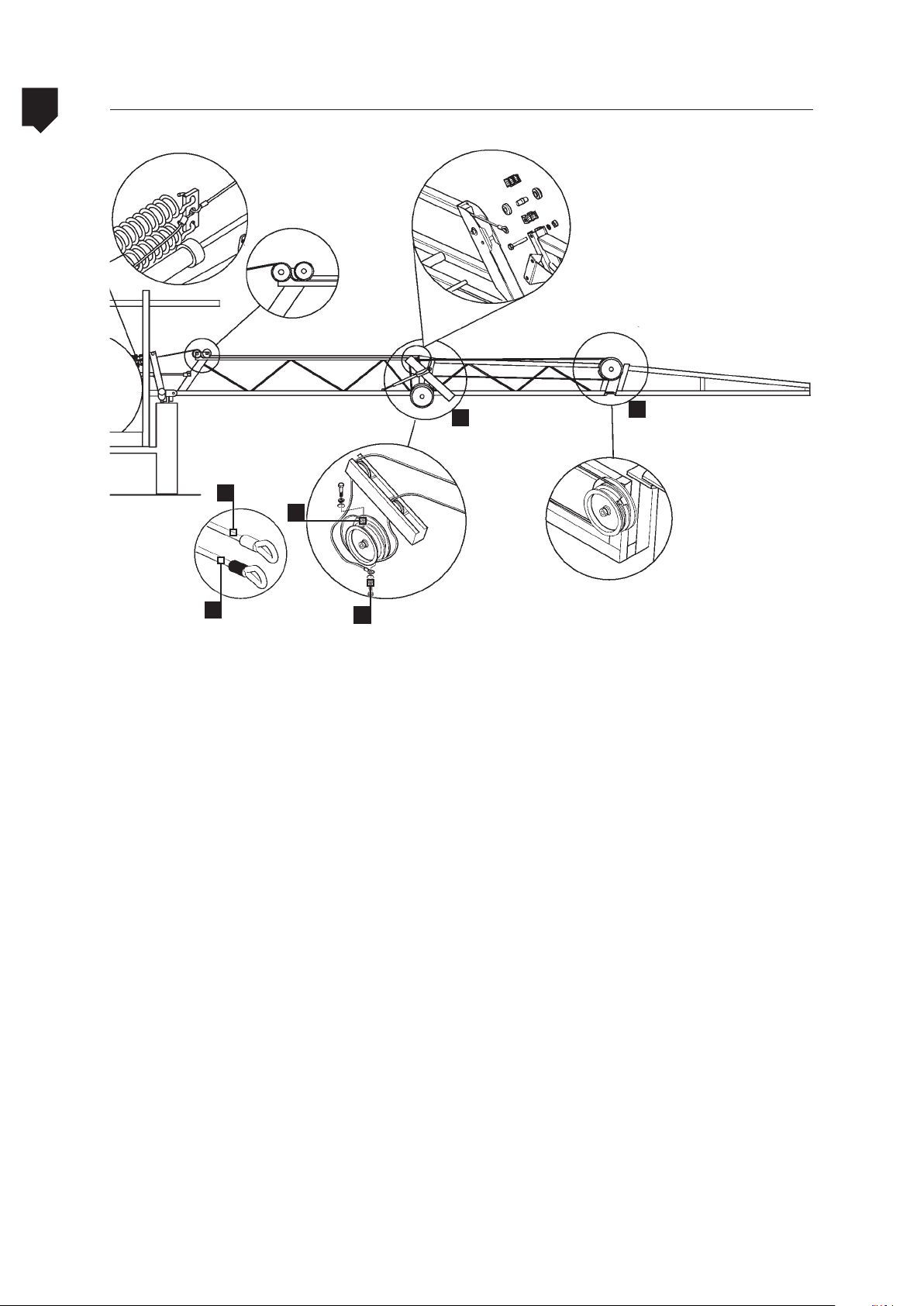
5
ADVANCE 2000Steel cables diagram
MAINTENANCE
1º segmento
B
B
A
Procedures:
• ith the booms unfolded, first install the
steel cable of the first boom section.
• Next, install the silver steel cable on the
second boom section (pulley 1).
A
2º segmento
1
• Then, install the orange steel cable on the
external pulley, also on the second boom
section (pulley 1).
• Lock the cables on the pulley 2.
2
5-92
Page 93
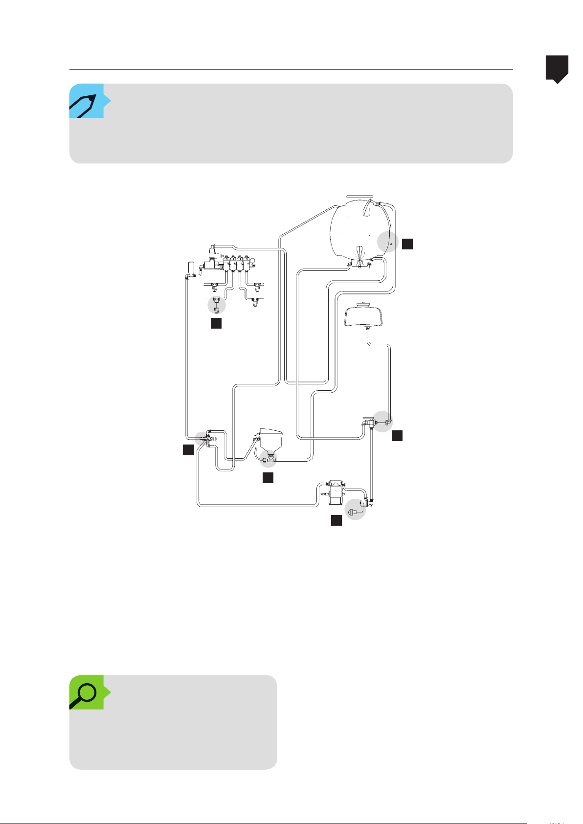
ADVANCE 2000 Winter storage
NOTE:
In areas where temperatures drop to 0° or less, the water accumulated in the spray
pump can freeze and cause serious damage.
A
E
5
MAINTENANCE
F
D
Procedures:
1. Drain the spray tank through the discharge valve (A).
2. Remove the suction filter cap (B).
3. Run the sprayer for about 30 seconds at
between half and low speed.
OBSERVATION:
To avoid damage to components, do not run the sprayer
over the recommended time.
C
B
4. Disconnect the inlet hose of the auxiliary
tank bypass valve (C).
5. Remove the in-line filter cap (D).
6. Operate the flow bypass valve lever (E) to
drain the circuit.
7. Reinstall the components in their place.
8. Repeat this operation at the end of each
working day during winter time to avoid
problems in future spray applications.
5-93
Page 94
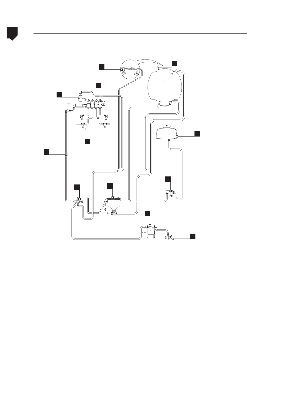
5
ADVANCE 2000Trouble-shooting
Components
12
MAINTENANCE
3
5
9
6
7
10
1
8
11
1. Spray tank
2. Suction filter
3. Spray control
4. Spray pump
5. Pressure hose
6. Return hose
9
2
7. In-line filter
8. Auxiliary tank
9. Flow bypass valve
10. Chemicals mixer
11. Auxiliary tank valve
12. Nozzles
5-94
Page 95
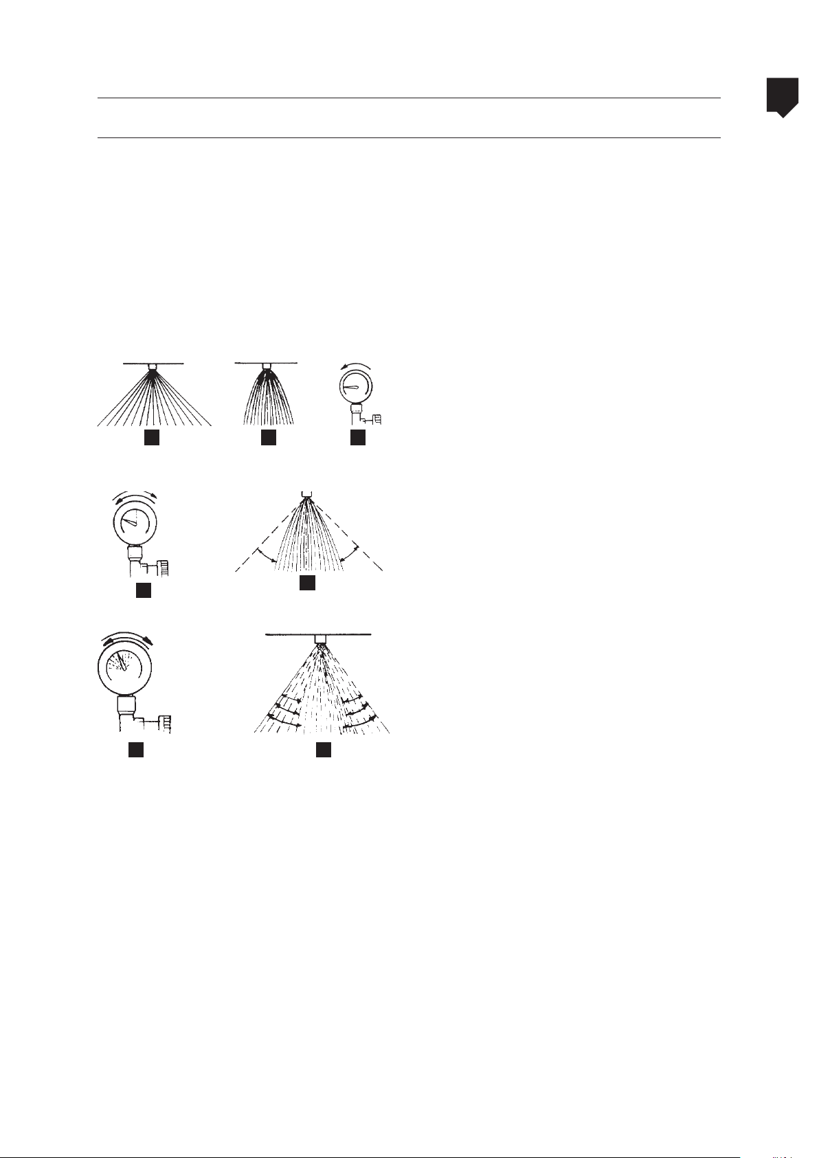
ADVANCE 2000 Trouble-shooting
Problems, causes and corrections
Whenever Jacto sprayers equipped with piston pumps present problems, try to classifiy
them in one of the following four groups.
5
a. Lack of suction and pumping capacity
• No liquid flow through the nozzles.
• No return to the tank.
• Pressure gauge does not indicate
pressure.
b. Pressure deficiency (partial lack of pressure)
• Desired pressure is not attained. (A);
• Specified nozzle spraying angle is not
A
D
E
CB
c. Pressure oscillation
d. Intermittent pressure
attained (B);
• Pressure gauge shows lower pressure (C).
• The pressure gauge needle oscillates (D);
• The nozzle spraying angle oscillates (E).
• The pressure gauge needle vibrates
with intensity (F);
• The pressure hoses vibrate with in-
tensity;
• The nozzles spraying angle varies (G).
MAINTENANCE
F G
5-95
Page 96

5
Problems, causes and corrections
Table 9: Lack of suction and pressure (total lack of pressure)
Probable causes Indications and corrections
1. No rotation of the agricultural
chemical pump.
MAINTENANCE
2. No water in the tank.
3. The 3 way valve on the lter is closed.
4. Dirt lter
5. Obstruction at the hose inlet.
The pump must be driven at 540 rpm. Visually
check to see if the pump is being driven.
For the agricultural chemical circuit to operate it is
necessary that there be at least a little liquid, otherwise there will be no pressure.
Due to the design of the 3 way valve, even when it is
in the closed position there will still be liquid owing when the pump operates, therefore there will be
insufcient ow.
The dirt lter will prevent the free ow of the liquid.
Clean the lter at every ll up or more frequently,
depending on the quality of the water and the type
of chemical product.
Check if see if the hose that connects the lter to the
pump is not folded.
Check if there are no obstructions in the hoses from
the tank to the lter. Fill the tank, open the tap and
check if water ow abundantly.
ADVANCE 2000
6. Entry of air.
7. Pump is not sucking.
Check the lter’s sealing ring.
The sealing of the lter must be tight, without leakages.
Remove the cover off the suction valves.
Check the condition of the valves and replace them
if necessary.
5-96
Page 97

ADVANCE 2000
Table 10: Insufficient pressure (partial lack of pressure)
Probable causes Indications and corrections
Problems, causes and corrections
5
1. Insufcient rotation in driving the agricultural chemical pump.
2. The 3 way valve on the lter is closed.
3 Filter is partially obstructed.
4. Inlet hose is partially obstructed.
5. Entry of air.
6. Pressure regulator. Check the valve and valve seat.
7. Excessive ow (ow from the nozzles
is above the recommended limit).
8. Pump has low replenishment rate.
The rotation to drive the pump must be that of 540 rpm.
Due to the design of the 3 way valve, even when it is
in the closed position there will still be liquid owing when the pump operates, therefore there will be
insufcient ow.
The lter must be clean so as to allow for the free
ow of the liquid.
If the pump is not correctly supplied it will cause a
drop in pressure.
Check to see if the hose that connects the lter to the
pump is not folded.
Check if there are no obstructions in the hoses from
the tank to the lter. Fill the tank, open the tap and
check if the water ows abundantly.
Check the connections and sealing rings at the out-
ow of the tank and the inow to the pump.
Check to see if the ow from the nozzles is within the
recommended limits (check the ow table)
Replace nozzles with a ow that is over 10%.
Only use nozzles recommended by the sprayer manufacturer.
Disconnect the pressure hose from the control.
Run the machine at 540 rpm at the pump.
Collect water for 1 minute. Measure the collected volume. The volume must be close to the rated volume
for the pump.
JP - 100 = 26.41 gpm JP - 150 = 39.62 gpm
JP - 75 = 19.81 gpm JP - 300 = 79.25 gpm
MAINTENANCE
.
5-97
Page 98

5
Problems, causes and corrections
Table 11: Oscillation in pressure
Probable causes Indications and corrections
Caused by a hole in the hose, damaged lter sealing
1. Entry of air into the inlet system.
ring, etc.
Check and repair any leaks if there are.
ADVANCE 2000
MAINTENANCE
2. Pressure regulator.
Table 12: Intermittence
Probable causes Indications and corrections
1. Tap closed.
2. Poor operation of the agricultural
chemical pump.
3. The pump head is internally damaged.
Check the valve and valve seat to ensure yourself
that these components are correctly adjusted
Due to the design of the 3 way valve, even when it is
in the closed position there will still be liquid owing when the pump operates, therefore there will be
insufcient ow.
Valve not sealing correctly due to impurities or jamming.
Replace the head of the agricultural chemical pump.
5-98
Page 99
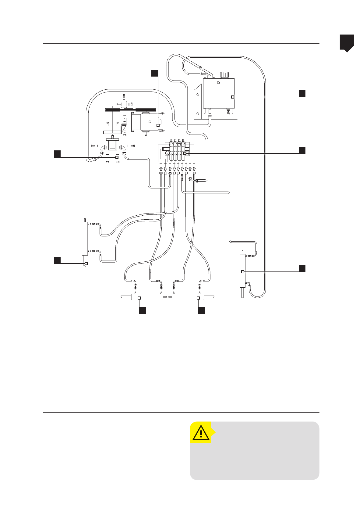
ADVANCE 2000
Advance 2000 AM-18 - Circuit hydraulic
5
1
CAPACIDADE:
4,4 LITROS
8
MAINTENANCE
2
3
7
6
4 5
1. Chemical pump
2. Hydraulic pump
3. Boom angular adjustment cylinder
4. Left boom actuation hydraulic cylinder
Hydraulic circuit characteristics
Pump rotation ..............................970 rpm
Pump ow rate ...........................2.11 gpm
Working pressure .......................... 2489 PSI
5. Right boom actuation hydraulic cylinder
6. Frame actuation hydraulic cylinders
7. Hydraulic boom control
8. Hydraulic oil reservoir
ATTENTION!
Use hydraulic oil with specification ISO VG-68, as shown in the
lubrication table.
5-99
Page 100
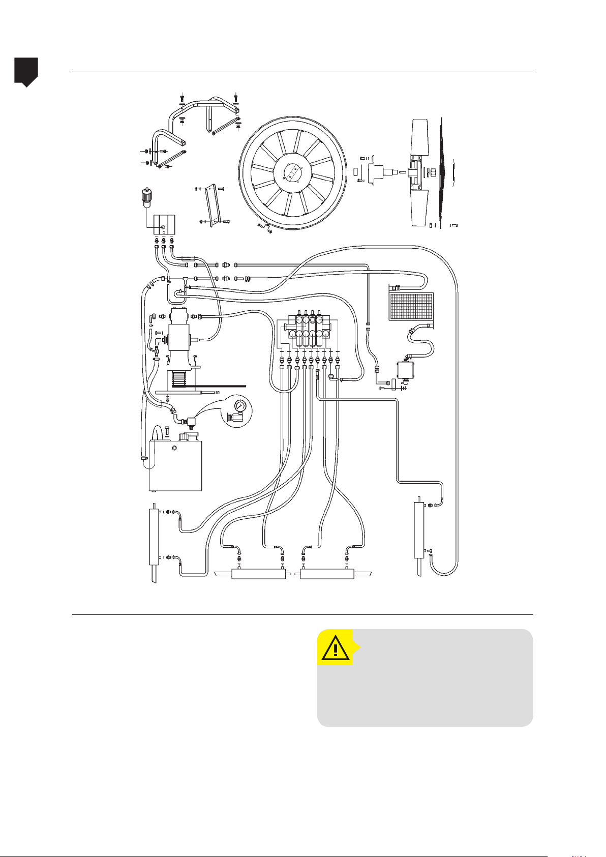
5
Advance 2000 VORTEX - Circuit hydraulic
ADVANCE 2000
MAINTENANCE
5-100
Hydraulic circuit characteristics
Working pressure ............................. 2489 PSI²
Pump average rotation ...................1570 rpm
Pump ow rate ...............................2.11 gpm
FAN:
Working pressure ............................. 2204 PSI²
Pump average rotation ...................1570 rpm
Pump ow rate .............................18.49 gpm
Fan rotation ............................. 3000 rpm
ATTENTION!
Use hydraulic oil with specification ISO VG-68, as shown
in the lubrication table.
 Loading...