


Parts & Maintenance
Manual
When Performance Matters.
™
WARNING
If incorrectly used, this machine can cause severe injury. Those who use
and maintain this machine should be trained in its proper use, warned of its
dangers, and should read the entire manual before attempting to set up,
operate, adjust, or service the machine.
4189623-Rev C
Tri King® Triplex Mower with ROPS
67069 – Kubota D722-E3B Engine
GB

11524 WILMAR BLVD,
CHARLOTTE, NC 28273
®
kg kW
1 800 848 1636 (US)
PRODUCT OF U.S.A.
A Textron Company
FOREWORD
This manual contains adjustment, maintenance,
troubleshooting instructions and parts list for your new
Jacobsen machine. This manual should be stored with
the equipment for reference during operation.
Before you operate your machine, you and each operator
you employ should read the manual carefully in its
entirety. By following the safety, operating and
maintenance instructions, you will prolong the life of your
equipment and maintain its maximum efficiency.
If additional information is needed, contact your
Jacobsen Dealer.
The serial plate is located on the left rear frame rail.
Jacobsen recommends you record these numbers below
for easy reference.
Suggested Stocking Guide
To Keep your Equipment fully operational and productive, Jacobsen suggests you maintain a stock of the more
commonly used maintenance items. We have included part numbers for additional support materials and training aids.
To order any of the following material:
1. Write your full name and complete address on your
order form.
2. Explain where and how to make shipment:
3. Order by the quantity desired, the part number, and
the description of the part.
4. Send or bring the order to your authorized Jacobsen
Dealer.
❑ UPS ❑ Regular Mail
❑ Overnight ❑ 2nd Day
Service Parts
Qty. Part No. Description Qty. Part No. Description
550489 Fuel Filter, Diesel Engine 549579 Hydraulic Oil Filter (2 Req’d)
5000913 Air Filter, Diesel Engine 3001950 Pump Drive Belt
502644 Oil Filter, Diesel Engine 1001958 Ignition Key Switch
Service Support Material
Qty. Part No. Description
4189624 Safety & Operation Manual
4189623 Parts & Maintenance
4189622 Engine Parts Catalog
4191622 DVD, Operator Training
Qty. Part No. Description
4171674 Service Manual
These are the original instructions verified by
Jacobsen, A Textron Company.
© 2012, Jacobsen A Textron Company/Textron Innovations Inc.
“All rights reserved, including the right to reproduce this material
2
or portions thereof in any form.”
Proposition 65 Warning
This product contains or emits
chemicals known to the State of
California to cause cancer and birth
defects or other reproductive harm.
LITHO IN U.S.A. 5-2012

Table of Contents
1 Safety
1.1 Operating Safety ........................................... 4
1.2 Important Safety Notes ................................. 5
2 Specifications
2.1 Product Identification .................................... 6
2.2 Engine ........................................................... 6
2.3 Cutting Units: ................................................ 6
2.4 Mower ........................................................... 6
2.5 Weights and Dimensions .............................. 7
2.6 Accessories & Support Literature ................. 7
2.7 Declaration of Conformity ............................. 8
3 Adjustments
3.1 General ....................................................... 10
3.2 Fan Belt ....................................................... 10
3.3 Pump Drive Belt .......................................... 10
3.4 Neutral and 3WD Switches ......................... 11
3.5 Parking Brake Switches .............................. 11
3.6 Lift Limit Switch ........................................... 11
3.7 Traction Pedal Neutral ................................ 12
3.8 Traction Pedal Forward Stop ...................... 12
3.9 Lift / Lower Pedal Stop ................................ 12
3.10 Parking Brake ............................................. 13
3.11 Rear Lift Arm ............................................... 13
3.12 Down Pressure ........................................... 13
3.13 Reel To Bedknife ........................................ 14
3.14 Reel to Bedknife Adjustment ....................... 14
3.15 Cutting Modes ............................................. 15
3.16 Cutting Height Adjustment .......................... 15
3.17 Removing the Cutting Unit .......................... 16
3.18 Cutting Height - Fixed Mode ....................... 16
3.19 Cutting Height - Floating Mode ................... 17
3.20 Torque Specification ................................... 18
3.21 Specific Torque ........................................... 18
4 Maintenance
4.1 General ....................................................... 19
4.2 Engine ......................................................... 19
4.3 Engine Oil ................................................... 20
4.4 Air Filter ....................................................... 20
4.5 Fuel ............................................................. 21
4.6 Fuel System ................................................ 21
4.7 Battery ......................................................... 21
4.8 Jump Starting .............................................. 22
4.9 Charging Battery ......................................... 22
4.10 Hydraulic Hoses .......................................... 22
4.11 Hydraulic Oil ................................................ 23
4.12 Hydraulic Oil Filters ..................................... 23
4.13 Electrical System ........................................ 23
4.14 Muffler and Exhaust .................................... 24
4.15 Tires ............................................................ 24
4.16 Wheel Mounting Procedure ........................ 24
4.17 Care and Cleaning ...................................... 25
4.18 Radiator ...................................................... 25
4.19 Backlapping ................................................ 26
4.20 Storage ....................................................... 27
5 Troubleshooting
5.1 General ....................................................... 28
6 Maintenance & Lubrication Charts
6.1 General ........................................................ 29
6.2 Lubrication Chart .........................................29
6.3 Maintenance Charts ..................................... 30
7Parts Catalog
7.1 Table Of Contents........................................ 31
3

1 SAFETY
!
1.1 OPERATING SAFETY ______________________________________________________
WARNING
EQUIPMENT OPERATED IMPROPERLY OR BY UNTRAINED PERSONNEL CAN BE DANGEROUS.
Familiarize yourself with the location and proper use of all controls. Inexperienced operators should receive
instruction from someone familiar with the equipment before being allowed to operate the machine.
1. Safety is dependent upon the awareness, concern,
and prudence of those who operate or service the
equipment. Never allow minors to operate any
equipment.
2. It is your responsibility to read this manual and all
publications associated with this equipment (Safety
and Operation Manual, Engine Manual, and
attachments/accessories instruction sheets). If the
operator cannot read English it is the owner’s
responsibility to explain the material contained in this
manual to them.
3. Learn the proper use of the machine, the location and
purpose of all the controls and gauges before you
operate the equipment. Working with unfamiliar
equipment can lead to accidents.
4. Never allow anyone to operate or service the machine
or its attachments without proper training and
instructions; or while under the influence of alcohol or
drugs.
5. Wear all the necessary protective clothing and personal
safety devices to protect your head, eyes, ears, hands,
and feet. Operate the machine only in daylight or in
good artificial light.
6. Evaluate the terrain to determine what accessories and
attachments are needed to properly and safely perform
the job. Only use accessories and attachments
approved by Jacobsen.
7. Stay alert for holes in the terrain and other hidden
hazards.
8. Inspect the area where the equipment will be used.
Pick up all the debris you can find before operating.
Beware of overhead obstructions (low tree limbs,
electrical wires, etc.) and also underground obstacles
(sprinklers, pipes, tree roots, etc.). Enter a new area
cautiously. Stay alert for hidden hazards.
9. Never direct discharge of material toward bystanders,
nor allow anyone near the machine while in operation.
The owner/operator can prevent and is responsible for
injuries inflicted to themselves, to bystanders, and
damage to property.
10. Do not carry passengers. Keep bystanders and pets a
safe distance away.
11. Never operate equipment that is not in perfect working
order or is without decals, guards, shields, discharge
deflectors, or other protective devices securely fastened
in place.
12. Never disconnect or bypass any switch.
13. Do not change the engine governor setting or
overspeed the engine.
14. Carbon monoxide in the exhaust fumes can be fatal
when inhaled. Never operate the engine without proper
ventilation or in an enclosed area.
15. Fuel is highly flammable; handle with care.
16. Keep the engine clean. Allow the engine to cool before
storing and always remove the ignition key.
17. Disengage all drives and engage parking brake before
starting the engine (motor). Start the engine only when
sitting in operator’s seat, never while standing beside
the unit.
18. Equipment must comply with the latest federal, state,
and local requirements when driven or transported on
public roads. Watch out for traffic when crossing or
operating on or near roads.
19. Local regulations may restrict the age of the operator.
20. Operate the machine up and down the face of slopes
(vertically), not across the face (horizontally).
21. To prevent tipping or loss of control, do not start or stop
suddenly on slopes. Reduce speed when making sharp
turns. Use caution when changing directions.
22. Always use the seat belt when operating mowers
equipped with a Roll Over Protective Structure (ROPS).
Never use a seat belt when operating mowers
without a ROPS.
Accessory operator protective structures will
continue to be offered for all equipment currently
covered. This allows for the outfitting of any
machines without previous ROPS installations or
replacement of damaged structures.
23. Keep legs, arms, and body inside the seating
compartment while the vehicle is in motion.
24. Disconnect battery and controller electrical connectors
before performing any welding on this mower.
This machine is to be operated and maintained as specified in this manual and is intended for the professional
maintenance of specialized turf grasses. It is not intended for use on rough terrain or long grasses.
4

SAFETY 1
!
!
1.2 IMPORTANT SAFETY NOTES ________________________________________________
This safety alert symbol is used to alert you to potential hazards.
DANGER - Indicates an imminently hazardous situation which, if not avoided, WILL result in death or serious injury.
WARNING - Indicates a potentially hazardous situation which, if not avoided, COULD result in death or serious
injury.
CAUTION - Indicates a potentially hazardous situation which, if not avoided, MAY result in minor or moderate injury
and property damage. It may also be used to alert against unsafe practices.
NOTICE - Indicates a potentially hazardous situation which, if not avoided, MAY result in property damage. It may
also be used to alert against unsafe practices.
For pictorial clarity, some illustrations in this manual may show shields, guards or plates open or removed. Under no
circumstances should this equipment be operated without these devices securely fastened in place.
WARNING
The Interlock System on this mower prevents the mower from starting unless
the brake lever is engaged, reel switch is off, and traction pedal is in Neutral.
The system will stop the engine if the operator leaves the seat without
engaging the parking brake or setting the reel switch off.
NEVER operate mower unless the Interlock System is working.
WARNING
1. Before leaving the operator’s position for any reason:
a. Return traction pedal to Neutral.
b. Disengage all drives.
c. Lower all implements to the ground.
d. Engage parking brake.
e. Stop engine and remove the ignition key.
2. Keep hands, feet, and clothing away from moving parts. Wait for all
movement to stop before you clean, adjust, or service the machine.
3. Keep the area of operation clear of all bystanders and pets.
4. Never carry passengers, unless a seat is provided for them.
5. Never operate mowing equipment without the discharge deflector
securely fastened in place.
By following all instructions in this manual, you will prolong the life of your machine and maintain its maximum
efficiency. Adjustments and maintenance should always be performed by a qualified technician.
If additional information or service is needed, contact your Authorized Jacobsen Dealer who is kept informed of the
latest methods to service this equipment and can provide prompt and efficient service.
5

2 SPECIFICATIONS
619 13.2 XXXX
67069001651
2.1 PRODUCT IDENTIFICATION_________________________________________________
67069.............................. Tri-King Mower, 3-WD, 17.7 hp
diesel engine with ROPS. Without
front lift arms or mowers.
PRODUCT OF U.S.A.
A Textron Company
®
11524 WILMAR BLVD,
CHARLOTTE, NC 28273
1 800 848 1636 (US)
Serial Number ................An identification plate, like the one
shown, listing the serial number, is
kg kW
attached to the frame of the
mower and is located to the
operator’s left just behind the front
wheel motor. Always provide the
serial number of the unit when
ordering replacement parts or
Product
EEC Sound
Power
Sound Pressure
Level
Operator Ear
Vibration M/S
Arms Body
requesting service information.
67069 99 dba 86 dba 3.78 0.016
2.2 ENGINE__________________________________________________________________
Make ...............................Kubota
Model ..............................D722-E3B
Horsepower..................... 17.7 hp (13.2 kW) @ 3200 rpm
Note: Actual sustained horsepower will likely be lower
than listed in specifications due to operating limitations
and environmental factors
Displacement .................. 43.88 cu. in. (719 cc)
Torque............................. 26 ft. lbs. (35 Nm) @ 2600 rpm
Fuel:
Type ..........................No. 2 Low or Ultra-Low Sulfur
Diesel
Rating ....................... Min. Cetane rating 45
Capacity.................... 6.5 U.S. Gal. (24.6 liters)
Governor......................... Ball Type Governor
Low Idle ................... 1450 RPM
High Idle ................... 3400 RPM
Lubrication:
Capacity.................... 3.4 quarts (3.2 liter) with filter
Type .......................... SAE 20W, SAE 30W
API Classification ..... CD, CE
Air Filter .......................... Dry type with evacuator valve and
service indicator
Alternator ........................ 40 amp
2
2.3 CUTTING UNITS: __________________________________________________________
Reel ................................ 3 Reels, 26 in. (660 mm) wide or,
3 Reels, 30 in. (762 mm) wide.
Reel Diameter................. 7 in. (178 mm)
Bearings.......................... Self adjusting tapered roller
bearings
Blade Options .................7 blades
Cutting Width:
2.4 MOWER _________________________________________________________________
Tires:
Front ......................... 20 x 10 - 10 tubeless
Rear .........................20 x 10 - 8 tubeless
Pressure:
Front.......................... 10-12 psi (0.69-0.82 BAR)
Rear ..........................8-10 psi (0.55-0.69 BAR)
Battery:
Type ..........................12 Volt Lead/Acid
Group........................ 22 NF
Parking Brake ................. Mechanical front wheel disk
6
Hand lever actuated
26 in. Reels............... 72 in. (1828 mm)
30 in. Reels............... 84 in. (2134 mm)
Overall Width:
26 in. Reels............... 78.5 in. (1994 mm)
30 in. Reels............... 90.5 in. (2298 mm)
Cutting Frequency:
7 Blade ..................... 0.151 in./mph (3.8 mm/kph)
Speed:
Mow ......................... 0 - 5 mph (8 kph)
Transport ................. 0 - 8.5 mph (13.7 kph)
Reverse .................... 0 - 2.3 mph (3.7 kph)
Hydraulic System:
Capacity.......................... 5.5 U.S. gal. (20.8 liters) System
Fluid Type ....................... GreensCare 68 Biodegradable
Charge Filter................... 10 micron
Return Line Filter ............ 10 micron
Steering ......................... Hydrostatic power steering

SPECIFICATIONS 2
!
2.5 WEIGHTS AND DIMENSIONS ________________________________________________
Dimensions: Inches (mm)
Length ............................................................. 99 (2519)
Height........................................................... 51.5 (1308)
Width - Wheel .............................................. 64.5 (1638)
Weights:...................................................... Lbs. (kg)
67069 (Base Mower, No Reels).................. 1445 (655)
2.6 ACCESSORIES & SUPPORT LITERATURE _____________________________________
Contact your area Jacobsen Dealer for a complete listing of accessories and attachments.
CAUTION
Use of other than Jacobsen authorized parts and accessories may cause personal injury or damage to the
equipment.
Accesories
Air Blow Gun ...........................................................JAC5098
Orange Touch-up Paint (12 oz. spray) ...................... 554598
2-Post ROPS with Seat Belt........................................ 69157
Light Kit ....................................................................... 69149
Arm Rest ................................................................. 4139431
Grass Catchers for 26 in. Reel.................................... 69151
Grass Catchers for 30 in. Reel.................................... 69150
600 RPM Reel Kit (Diesel Units)............................. 5003062
Down Pressure Kit .................................................. 1002588
Reels
7 Blade, 26 in. Left Hand Reel .................................... 67114
7 Blade, 26 in. Right Hand Reel.................................. 67115
7 Blade, 26 in. Center Reel......................................... 67116
7 Blade, 30 in. Left Hand Reel .................................... 67123
7 Blade, 30 in. Right Hand Reel.................................. 67124
7 Blade, 30 in. Center Reel......................................... 67125
Vertical Mower, 26 in. Left Hand ................................. 67139
Vertical Mower, 26 in. Right Hand ............................... 67140
Vertical Mower, 26 in. Center ...................................... 67141
Rollers
Grooved Front Roller (Steel) for 26 in. Reel.................67731
Grooved Front Roller (Steel) for 30 in. Reel.................67729
Solid Roller for 26 in. Reel ......................................... 132639
Solid Roller for 30 in. Reel ......................................... 132640
Grooved Front Roller Scraper for 26 in. Reel...............69147
Grooved Front Roller Scraper for 30 in. Reel...............69148
Rear Roller Scraper for 26 in. Reel..............................67909
Rear Roller Scraper for 30 in. Reel..............................67910
Support Literature
Safety & Operation Manual......................................4189624
Parts & Maintenance Manual...................................4189623
Diesel Engine Parts Catalog.................................... 4189622
Operator Training DVD............................................. 4191622
Service & Repair Manual ......................................... 4171674
7

2 SPECIFICATIONS
2.7 DECLARATION OF CONFORMITY ____________________________________________
DECLARATION OF CONFORMITY ▪ ДЕКЛАРАЦИЯ ЗА СЪОТВЕТСТВИЕ ▪ PROHLÁŠENÍ O SHODĚ ▪
OVERENSSTEMMELSESERKLÆRING ▪ CONFORMITEITSVERKLARING ▪ VASTAVUSDEKLARATSIOON ▪
VAATIMUSTENMUKAISUUSVAKUUTUS ▪ DECLARATION DE CONFORMITE ▪ KONFORMITÄTSERKLÄRUNG ▪
ΔΗΛΩΣΗ ΣΥΜΜΟΡΦΩΣΗΣ ▪ MEGFELELŐSÉGI NYILATKOZAT ▪ DICHIARAZIONE DI CONFORMITÀ ▪ ATBILSTĪBAS
DEKLARĀCIJA ▪ ATITIKTIES DEKLARACIJA ▪ DIKJARAZZJONI TAL-KONFORMITÀ ▪ DEKLARACJA ZGODNOŚCI ▪
DECLARAÇÃO DE CONFORMIDADE ▪ DECLARAŢIE DE CONFORMITATE ▪ VYHLÁSENIE O ZHODE ▪ IZJAVA O
SKLADNOSTI ▪ DECLARACIÓN DE CONFORMIDAD ▪ DEKLARATION OM ÖVERENSSTÄMMELSE
Business name and full address of the manufacturer ▪ Търговско име и пълен адрес на производителя ▪ Obchodní jméno a plná adresa výrobce ▪
Producentens firmanavn og fulde adresse ▪ Bedrijfsnaam en volledig adres van de fabrikant ▪ Tootja ärinimi ja täielik aadress ▪
Valmistajan toiminimi ja täydellinen osoite ▪ Nom commercial et adresse complète du fabricant ▪ Firmenname und vollständige Adresse des Herstellers ▪
Επωνυμία και ταχυδρομική διεύθυνση κατασκευαστή ▪ A gyártó üzleti neve és teljes címe ▪ Ragione sociale e indirizzo completo del fabbricante ▪
Uzņēmuma nosaukums un pilna ražotāja adrese ▪ Verslo pavadinimas ir pilnas gamintojo adresas ▪ Isem kummerċjali u indirizz sħiħ tal-fabbrikant ▪
Nazwa firmy i pełny adres producenta ▪ Nome da empresa e endereço completo do fabricante ▪ Denumirea comercială şi adresa completă a
producătorului ▪ Obchodný názov a úplná adresa výrobcu ▪ Naziv podjetja in polni naslov proizvajalca ▪ Nombre de la empresa y dirección completa del
fabricante ▪ Tillverkarens företagsnamn och kompletta adress
Product Code ▪ Код на пр
▪ Termékkód ▪ Codice prodotto ▪ Produkta kods ▪ Produkto kodas ▪ Kodiċi tal-Prodott ▪ Kod produktu ▪ Código do Produto ▪ Cod produs ▪ Kód výrobku ▪
Oznaka proizvoda ▪ Código de producto ▪ Produktkod
Machine Name ▪ Наименование на машината ▪ Název stroje ▪ Maskinnavn ▪ Machinenaam ▪ Masina nimi ▪ Laitteen nimi ▪ Nom de la machine ▪
Maschinenbezeichnung ▪ Ονομασία μηχανήματος ▪ Gépnév ▪ Denominazione della macchina ▪ Iekārtas nosaukums ▪ Mašinos pavadinimas ▪ Isem talMagna ▪ Nazwa urządzenia ▪ Nome da Máquina ▪ Numele echipamentului ▪ N
Designation ▪ Предназначение ▪ Označení ▪ Betegnelse ▪ Benaming ▪ Nimetus ▪ Tyyppimerkintä ▪ Pažymėjimas ▪ Bezeichnung ▪ Χαρακτηρισμός ▪
Megnevezés ▪ Funzione ▪ Apzīmējums ▪ Lithuanian ▪ Denominazzjoni ▪ Oznaczenie ▪ Designação ▪ Specificaţie ▪ Označenie ▪ Namen stroja ▪ Descripción
▪ Beteckning
Serial Number ▪ Сериен номер ▪ Sériové číslo ▪ Serienummer ▪ Serienummer ▪ Seerianumber ▪ Valmistusnumero ▪ Numéro de série ▪ Seriennummer ▪
Σειριακός αριθμός ▪ Sorozatszám ▪ Num
serie ▪ Sériové číslo ▪ Serijska številka ▪ Número de serie ▪ Serienummer
Engine ▪ Двигател ▪ Motor ▪ Motor ▪ Motor ▪ Mootor ▪ Moottori ▪ Moteur ▪ Motor ▪ Μηχανή ▪ Modulnév ▪ Motore ▪ Dzinējs ▪ Variklis ▪ Saħħa Netta Installata ▪
Silnik ▪ Motor ▪ Motor ▪ Motor ▪ Motor ▪ Motor ▪ Motor
Net Installed Power ▪ Нетна инсталирана мощност ▪ Čistý instalovaný výkon ▪ Installeret nettoeffekt ▪ Netto geïnstalleerd vermogen ▪ Inst
netovõimsus ▪ Asennettu nettoteho ▪ Puissance nominale nette ▪ Installierte Nettoleistung ▪ Καθαρή εγκατεστημένη ισχύς ▪ Nettó beép tett teljesítmény ▪
Potenza netta installata ▪ Paredzētā tīkla jauda ▪ Grynoji galia ▪ Wisa’ tal-Qtugħ ▪ Moc zainstalowana netto ▪ Potência instalada ▪ Puterea instalată netă ▪
Čistý inštalovaný výkon ▪ Neto vgrajena moč ▪ Potencia instalada neta ▪ Nettoeffekt
Cutting Width ▪ Широчина на рязане ▪ Šířka řezu ▪ Skærebredde ▪ Maaibreedte ▪ Lõikelaius ▪ Leikkuuleveys ▪ Largeur de coupe ▪ Schnittbreite ▪
Μήκος μισινέζας ▪ Vágási szélesség ▪ Larghezza di taglio ▪ Griešanas platums ▪ Pjovimo plotis ▪ Tikkonforma mad-Direttivi ▪ Szer
Largura de Corte ▪ Lăţimea de tăiere ▪ Šírka záberu ▪ Širina reza ▪ Anchura de corte ▪ Klippbredd
Conforms to Directives ▪ В съответствие с директивите ▪ Splňuje podmínky směrnic ▪ Er i overensstemmelse med direktiver ▪ Voldoet aan de richtlijnen ▪
Vastab direktiividele ▪ Direktiivien mukainen ▪ Conforme aux directives ▪ Entspricht Richtlinien ▪ Ακολουθήστε πιστά τις Οδηγίες ▪ Megfelel az irányelveknek
▪ Conforme alle Direttive ▪ Atbilst direktīvām ▪ Atitinka direktyvų reikalavimus ▪ Valutazzjoni tal-Konformità ▪ Dyrektywy związane ▪ Cumpre as Directivas ▪
Respectă Directivele ▪ Je v súlade so smernicami ▪ Skladnost z direktivami ▪ Cumple con las Directivas ▪ Uppfyller direktiv
Conformity Assessment ▪ Оценка за съответствие ▪ Hodnocení plnění podmínek ▪ Overensstemmelsesvurdering ▪ Conformiteitsbeoordeling ▪
Vastavushindamine ▪ Vaatimustenmukaisuuden arviointi ▪ Evaluation de conformité ▪ Konformitätsbeurteilung ▪ Διαπίστωση Συμμόρφωσης ▪
Megfelelőség-értékelés ▪ Valutazione della conformità ▪ Atbilstības novērtējums ▪ Atitikties įvertinimas ▪ Livell tal-Qawwa tal-Ħoss Imkejjel ▪ Ocena
zgodności ▪ Avaliação de Conformidade ▪ Evaluarea conformităţii ▪ Vyhodnotenie zhodnosti ▪ Ocena skladnosti ▪ Evaluación de conformidad ▪
Bedömning av överensstämmelse
Measured Sound Power Level ▪ Измерено ниво на звукова мощност ▪ Naměřený akustický výkon ▪ Målte lydstyrkeniveau ▪ Gemeten geluidsniveau ▪
Mõõdetud helivõimsuse tase ▪ Mit
Σταθμισμένο επίπεδο ηχητικής ισχύος ▪ Mért hangteljesítményszint ▪ Livello di potenza sonora misurato ▪ Izmērītais skaņas jaudas līmenis ▪
Išmatuotas garso stiprumo lygis ▪ Livell tal-Qawwa tal-Ħoss Iggarantit ▪ Moc akustyczna mierzona ▪ Nível sonoro medido ▪ Nivelul măsurat al puterii
acustice ▪ Nameraná hladina akustického výkonu ▪ Izmerjena raven zvočne moči ▪ Nivel de potencia sonora medido ▪ Uppmätt ljudeffektsnivå
Guaranteed Sound Power Level ▪ Гарантирано ниво на звукова мощност ▪ Garantovaný akustický výkon ▪ Garanteret lydstyrkeniveau ▪
Gegarandeerd geluidsniveau ▪ Garanteeritud helivõimsuse tase ▪ Taattu äänitehotaso ▪ Niveau de puissance sonore garanti ▪ Garantierter
Schalldruckpegel ▪ Εγγυημένο επίπεδο ηχητικής ισχύος ▪ Szavatolt hangteljesítményszint ▪ Livello di pote
jaudas līmenis ▪ Garantuotas garso stiprumo lygis ▪ Livell tal-Qawwa tal-Ħoss Iggarantit ▪ Moc akustyczna gwarantowana ▪ Nível sonoro farantido ▪
Nivelul garantat al puterii acustice ▪ Garantovaná hladina akustického výkonu ▪ Zajamčena raven zvočne moči ▪ Nivel de potencia sonora garantizado ▪
Garanterad ljudeffektsnivå
Conformity Assessment Procedure (Noise) ▪ Оценка за съответствие на процедурата (Шум) ▪ Postup hodnocení plnění podmínek (hluk) ▪
Procedure for overensstemmelsesvurdering (Støj) ▪ Procedure van de conformiteitsbeoordeling (geluid) ▪ Vastavushindamismenetlus (müra) ▪
Vaatimustenmukaisuuden arviointimenettely (Melu) ▪ Procédure d’évaluation de conformité (bruit) ▪ Konformitätsbeurteilungsverfahren (Geräusch) ▪
Διαδικασία Αξιολόγησης Συμμόρφωσης (Θόρυβος) ▪ Megfelelőség-értékelési eljárás (Zaj) ▪ Procedura di valutazione della conformità (rumore) ▪
Atbilstības novērtējuma procedūra (troksnis) ▪ Atitikties įver
Procedura oceny zgodności (poziom hałasu) ▪ Processo de avaliação de conformidade (nível sonoro) Procedura de evaluare a conformităţii (zgomot) ▪
Postup vyhodnocovania zhodnosti (hluk) ▪ Postopek za ugotavljanje skladnosti (hrup) ▪ Procedimiento de evaluación de conformidad (ruido) ▪
Procedur för bedömning av överensstämmelse (buller)
UK Notified Body for 2000/14/EC ▪ Нотифициран орган в Обединеното кралство за 2000/14/ЕО ▪ Úřad certifikovaný podle směrnice č. 2000/14/EC ▪
Det britiske bemyndigede organ for 2001/14/EF ▪ Engels adviesorgaan voor 2000/14/EG ▪ Ühendkuningriigi teavitatud asutus direktiivi 2000/14/EÜ
mõistes ▪ Direktiivin 2000/14/EY mukainen ilmoitettu tarkastuslaitos Isossa-Britanniassa ▪ Organisme notifié concernant la directive 2000/14/CE ▪
Britische benannte Stelle für 2000/14/EG ▪ Κοινοποιημένος Οργανισμός Ηνωμένου Βασιλείου για 2000/14/ΕΚ ▪
2000/14/EK – egyesült királyságbeli bejelentett szervezet ▪ Organismo Notificato in GB per 2000/14/CE ▪ 2000/14/EK AK reģistrētā organizācija ▪
JK notifikuotosio
14/WE ▪ Entidade notificada no Reino Unido para 2000/14/CE ▪ Organism notificat în Marea Britanie pentru 2000/14/CE ▪
Notifikovaný orgán Spojeného kráľovstva pre smernicu 2000/14/ES ▪ Britanski priglašeni organ za 2000/14/ES ▪
Cuerpo notificado en el Reino Unido para 2000/14/CE ▪ Anmält organ för 2000/14/EG i Storbritannien
Operator Ear Noise Level ▪ Оператор на нивото на доловим от ухото шум ▪ Hladina hluku v oblasti uší operátora ▪ Støjniveau i førers ørehøjde ▪
Geluidsniveau oor bestuurder ▪ Müratase operaatori kõrvas ▪ Melutaso käyttäjän korvan kohdalla ▪ Niveau de bruit à hauteur des oreilles de l’opérateur ▪
Schallpegel am Bedienerohr ▪ Επίπεδο θορύβου σε λειτουργία ▪ A kezelő fülénél mért zajszint ▪ Livello di potenza sonora all’orecchio dell’operatore ▪
Trokšņa līmenis pie operatora auss ▪ Dirbančiojo su mašina patiriamo triukšmo lygis ▪ Livell tal-Ħoss fil-Widna tal-Operatur ▪
Dopuszczalny poziom hałasu dla o
Hladina hluku pôsobiaca na sluch operátora ▪ Raven hrupa pri ušesu upravljavca ▪ Nivel sonoro en el oído del operador ▪ Ljudnivå vid förarens öra
одукта ▪ Kód výrobku ▪ Produktkode ▪ Productcode ▪ Toote kood ▪ Tuotekoodi ▪ Code produit ▪ Produktcode ▪ Κωδικός προϊόντος
ázov stroja ▪ Naziv stroja ▪ Nombre de la máquina ▪ Maskinens namn
ero di serie ▪ Sērijas numurs ▪ Serijos numeris ▪ Numru Serjali ▪ Numer seryjny ▪ Número de Série ▪ Număr de
alleeritud
okość cięcia ▪
attu äänitehotaso ▪ Niveau de puissance sonore mesuré ▪ Gemessener Schalldruckpegel ▪
nza sonora garantito ▪ Garantētais skaņas
tinimo procedūra (garsas) ▪ Proċedura tal-Valutazzjoni tal-Konformità (Ħoss) ▪
s įstaigos 2000/14/EC ▪ Korp Notifikat tar-Renju Unit għal 2000/14/KE ▪ Dopuszczona jednostka badawcza w Wielkiej Brytanii wg 2000/
peratora ▪ Nível sonoro nos ouvidos do operador ▪ Nivelul zgomotului la urechea operatorului ▪
Jacobsen, A Textron Company
11524 Wilmar Blvd.
Charlotte, NC 28273, USA
67069
Tri-King 3WD
Lawnmower, Article 12, Item 32
6706901651-6706902500
Kubota D722-E3B Diesel
13,2 kW @ 3200 RPM
83 / 213 cm
2004/108/EC
2006/42/EC
200
0/14/EC, 2005/88/EC
2006/66/EC
2006/42/EC Annex VIII
99 dB(A) LWA
99 dB(A) LWA
2000/14/EC Annex VI, Part 1
Sound Research Laboratories Limited
86 dB(a) Leq (2006/42/EC)
Number: 1088
Holbrook House, Little Waldingfield
Sudbury, Suffolk CO10 0TH
8

SPECIFICATIONS 2
Harmonised standards used ▪ Използвани хармонизирани стандарти ▪ Použité harmonizované normy ▪ Brugte harmoniserede standarder ▪
Gebruikte geharmoniseerde standaards ▪ Kasutatud ühtlustatud standardid ▪ Käytetyt yhdenmukaistetut standardit ▪ Normes harmonisées utilisées ▪
Angewandte harmonisierte Normen ▪ Εναρμονισμένα πρότυπα που χρησιμοποιήθηκαν ▪ Harmonizált szabványok ▪ Standard armonizzati applicati ▪
Izmantotie saskaņotie standarti ▪ Panaudoti suderinti standartai ▪ Standards armonizzati użati ▪ Normy spójne powiązane ▪ Normas harmonizadas usadas
▪ Standardele armonizate utilizate ▪ Použité harmonizované normy ▪ Uporabljeni usklajeni standardi ▪ Estándares armonizados utilizados ▪
Harmoniserade standarder som används
Technical standards and specifications used ▪ Използвани технически стандарти и спецификации ▪ Použité technické normy a specifikace ▪
Brugte tekniske standarder og specifikationer ▪ Gebruikte technische standaards en specificaties ▪ Kasutatud tehnilised standardid ja spetsifikatsioonid ▪
Käytetyt tekniset standardit ja eritelmät ▪ Spécifications et normes techniques utilisées ▪ Angewandte technische Normen und Spezifikationen ▪
Τεχν ι κ ά πρό
Izmantotie tehniskie standarti un specifikācijas ▪ Panaudoti techniniai standartai ir techninė informacija ▪ Standards u speċifikazzjonijiet tekniċi użati ▪
Normy i specyfikacje techniczne powiązane ▪ Normas técnicas e especificações usadas ▪ Standardele tehnice şi specificaţiile utilizate ▪
Použité technické normy a špecifikácie ▪ Uporabljeni tehnični standardi in specifikacije ▪ Estándares y especificaciones técnicas utilizadas ▪
Tekniska standarder och specifikationer som används
The place and date of the declaration ▪ Място и дата на декларацията ▪ Místo a datum prohlášení ▪ Sted og dato for erklæringen ▪
Plaats en datum van de verklaring ▪ Deklaratsiooni väljastamise koht ja kuupäev ▪ Vakuutuksen paikka ja päivämäärä ▪ Lieu et date de la déclaration ▪
Ort und Datum der Erklärung ▪ Τόπ ο ς και ημερομηνία δήλωσης ▪ A nyilatkozat kelte
Deklarācijas vieta un datums ▪ Deklaracijos vieta ir data ▪ Il-post u d-data tad-dikjarazzjoni ▪ Miejsce i data wystawienia deklaracji ▪ Local e data da
declaração ▪ Locul şi data declaraţiei ▪ Miesto a dátum vyhlásenia ▪ Kraj in datum izjave ▪ Lugar y fecha de la declaración ▪ Plats och datum för
deklarationen
Signature of the person empowered to draw up the declaration on behalf of the manufacturer, holds the technical documentation and is authorised to
compile the technical file, and who is established in the Community.
Подпис на човека, упълномощен да състави декларацията от името на производителя, който поддържащ техническата документация и е
оторизиран да изготви техническия файл и е регистриран в общността.
Podpis osoby oprávněné sestavit prohlášení jménem výrobce, držet technickou dokumentaci a osoby oprávněné sestavit technické soubory a založené v
rámci Evropského společenství.
Underskrift af personen, der har fuldmagt til at udarbejde erklæringen på vegne af producenten, der er indehaver af dokumentatio
at udarbejde den tekniske journal, og som er baseret i nærområdet.
Handtekening van de persoon die bevoegd is de verklaring namens de fabrikant te tekenen, de technische documentatie bewaart en bevoegd is om het
technische bestand samen te stellen, en die is gevestigd in het Woongebied.
Ühenduse registrisse kantud isiku allkiri, kes on volitatud tootja nimel deklaratsiooni koostama, kes omab tehnilist dokumentatsiooni ja kellel on õigus
koostada tehniline toimik.
Sen henkilön allekirjoitus, jolla on valmistajan valtuutus vakuutuksen laadintaan, jolla on hallussaan tekniset asiakirjat, joka on valtuutettu laatimaan
tekniset asiakirjat ja joka on sijoittautunut yhteisöön.
Signature de la personne habilitée à rédiger la déclaration au nom du fabricant, à détenir la documentation technique, à compiler les fichiers techniques et
qui est implantée dans la Communauté.
Unterschrift der Person, die berechtigt ist, die Erklärung im Namen des Herstellers abzugeben, die die technischen Unterlagen aufbewahrt und berechtigt
ist, die technischen Unterlagen zusammenzustellen, und die in der Gemeinschaft niedergelassen ist.
Υπογραφή ατόμου εξουσιοδοτημένου για την σύνταξη της δήλωσης εκ μέρους του κατασκευαστή, ο οποίος κατέχει την τεχνική έκθεση και έχει την
εξουσιοδότηση να ταξινομήσει τον τεχνικό φάκελο και ο οποίος είναι διορισμένος στην Κοινότητα.
A gyártó nevében meghatalmazott személy, akinek jogában áll módosítania a nyilatkozatot, a műszaki dokumentációt őrzi, engedéllyel rendelkezik a
műszaki fájl összeállításához, és aki a közösségben letelepedett személy.
Firma della persona autorizzata a redigere la dichiarazione a nome del fabbricante, in possesso Della documentazione tecnica ed autorizzata a costituire
il fascicolo tecnico, che deve essere stabilita nella Comunità.
Tās personas paraksts, kura ir pilnvarota deklarācijas sastādīšana
reģistru un kura ir apstiprināta Kopienā.
Asmuo, kuris yra gana žinomas, kuriam gamintojas suteikė įgaliojimus sudaryti šią deklaraciją, ir kuris ją pasirašė, turi visą techninę informaciją ir yra
įgaliotas sudaryti techninės informacijos dokumentą.
Il-firma tal-persuna awtorizzata li tfassal id-dikjarazzjoni f’isem il-fabbrikant, għandha d-dokumentazzjoni teknika u hija awtorizzata li tikkompila l-fajl
tekniku u li hija stabbilita fil-Komunità.
Podpis osoby upoważnionej do sporządzenia deklaracji w imieniu producenta, przechowującej dokumentację techniczną, upoważnioną do stworzenia
dokumentacji technicznej oraz wyznaczonej ds. wspólnotowych.
Assinatura da pessoa com poderes para emitir a declaração em nome do fabricante, que possui a documentação técnica, que está autorizada a compilar
o processo técnico e que está estabelecida na Comunidade.
Semnătura persoanei împuternicite să elaboreze declaraţia în numele producătorului, care deţine documentaţia tehnică, este autorizată să compileze
dosarul tehnic şi este stabilită în Comunitate.
Podpis osoby poverenej vystavením vyhlásenia v mene výrobcu, ktorá má technickú dokumentáciu a je oprávnená spracovať technické podklady a ktorá
je umiestnená v Spoločenstve.
Podpis osebe, pooblaščene za izdelavo izjave v imenu proizvajalca, ki ima tehnično dokumentacijo in lahko sestavlja spis tehnične
sedež v Skupnosti.
Firma de la persona responsable de la declaración en nombre del fabricante, que posee la documentación técnica y está autorizada para recopilar el
archivo técnico y que está establecido en la Comunidad.
Undertecknas av den som bemyndigad att upprätta deklarationen å tillverkarens vägnar, innehar den tekniska dokumentationen och är bemyndigad att
sammanställa den tekniska informationen och som är etablerad i gemenskapen.
Certificate Number ▪ Номер на сертификат ▪ Číslo osvědčení ▪ Certifikatnummer ▪ Certificaatnummer ▪ Sertifikaadi number ▪ Hyväksyntänumero ▪
Numéro de certificat ▪ Bescheinigungsnummer ▪ Αριθμός Πιστοποιητικού ▪ Hitelesítési szám ▪ Numero del certificato ▪ Sertifikāta numurs ▪
Sertifikato numeris ▪ Numru taċ-Ċertifikat ▪ Numer certyfikatu ▪ Número do Certificado ▪ Număr certificat ▪ Číslo osvedčenia ▪ Številka certifikata ▪
Número de certificado ▪ Certifikatsnummer
τυπα και προδιαγραφές που χρησιμοποιήθηκαν ▪ Műszaki szabványok és specifikációk ▪ Standard tecnici e specifiche applicati ▪
(hely és idő) ▪ Luogo e data della dichiarazione ▪
nen og er bemyndiget til
i ražotāja vārdā, kurai ir tehniskā dokumentācija, kura ir pilnvarota sagatavot tehnisko
dokumentacije, ter ima
BS EN ISO 20643
BS EN ISO 5349-1
BS EN ISO 5349-2
BS EN 836
B71.4
ISO 2631-1
SAE J1194
Jacobsen, A Textron Company
11524 Wilmar Blvd.
Charlotte, NC 28273, USA
May 7th, 2012
2006/42/EC Annex II 1.A.2
Tim Lansdell
Technical Director
Ransomes Jacobsen Limited
West Road, Ransomes Europark,
Ipswich, IP3 9TT, England
2006/42/EC Annex II 1 A.10
Vasant Godhalekar
VP of Engineering
Jacobsen, A Textron Company
11524 Wilmar Blvd,
Charlotte, NC 28273, USA
4189623 Rev C
GB BG CZ DK NL EE FI FR DE GR HU
българскиEnglish čeština dansk Nederlands eesti suomi français Deutsch Ελληνικά magyar
IT LV LT MT PL PT RO SK SI ES SE
italiano lietuvių
latviešu
valoda
kalba
Malki polski português Română slovenčina slovenščina Ελληνικά Svenska
9

3 ADJUSTMENTS
!
!
A
B
D
E
C
3.1 GENERAL________________________________________________________________
adjustment cannot be made, contact an authorized
WARNING
To prevent injury, lower implements to the ground,
disengage all drives, engage parking brake, stop engine,
and remove key from ignition switch before making any
adjustments or performing maintenance.
Jacobsen Dealer.
2. Replace, do not adjust, worn or damaged components.
3. Do not wear jewelry or loose fitting clothing when
making adjustments or repairs.
Make sure the mower is parked on a solid and level
surface. Never work on a mower that is supported only
by the jack. Always use jack stands.
If only the front or rear of the mower is raised, place
chocks in front of and behind the wheels that are not
raised.
1. Adjustments and maintenance should always be
performed by a qualified technician. If proper
Be careful to prevent entrapment of the hands and
fingers between moving and fixed components of the
machine.
4. Do not change governor settings or overspeed the
engine.
CAUTION
3.2 FAN BELT________________________________________________________________
Inspect and adjust new belt after first ten hours of
operation. Adjust every 100 hours thereafter.
1. Adjust alternator pulley so belt (B) deflects 9/32 to
11/32 in. (7 to 9 mm) with a 22 lb. (10 kg) push at
midspan between pulleys.
2. If tension is incorrect, loosen alternator mounting
bolts (A), and adjust alternator until proper belt
tension is achieved. Tighten hardware (A).
3.3 PUMP DRIVE BELT ________________________________________________________
Adjust reel pump belt (C) to deflect 1/4 in. (6 mm) with a
force of 5-7 lb. (2-3 kg) applied at midspan.
1. Loosen hardware (D and E).
2. Move pump/clutch assembly down to increase
tension on belt (C) then tighten hardware (D and E).
3. Torque hardware (D and E) to 27 - 33 ft. lb. (37-45
Nm).
10
Figure 3A
Figure 3B

ADJUSTMENTS 3
G
H
F
K
L
M
3.4 NEUTRAL AND 3WD SWITCHES _____________________________________________
1. Check traction pedal adjustment.
2. Use a volt/ohm meter to determine when switch
opens or closes.
a. Adjust switch (G) so “finger” of actuating arm (F)
is centered over sensing portion of switch.
Switch contacts should be closed with traction
pedal in neutral and open with minimal pedal
travel in forward or reverse direction.
b. Adjust 3WD switch (H) so contacts are open with
traction pedal in neutral, and contacts close with
minimal pedal travel in forward direction.
Figure 3C
3.5 PARKING BRAKE SWITCHES________________________________________________
Loosen screws (K) and adjust both switches so contacts
just close as the brake lever is moved to the engaged
position then tighten screws.
Figure 3D
3.6 LIFT LIMIT SWITCH ________________________________________________________
The lift limit switch must be adjusted so the reels stop
turning before the cutting plane between the reel and
ground reach 15-3/4 in. (400 mm). To adjust, loosen
screw (L), and adjust arm (M).
Figure 3E
11

3 ADJUSTMENTS
O
N
N
Front
P
P
Q
S
R
3.7 TRACTION PEDAL NEUTRAL________________________________________________
1. If the mower “creeps” in either direction when the
engine is running, but the traction pedal is not
depressed, adjust spring tension so that the pedal
always returns to neutral when released.
Note: The mower may “creep” when the hydraulic oil
is cold. Operate the mower for 15 minutes before
determining if adjustment is required.
2. Use extreme caution when making this adjustment
as the wheels will be off the ground and the engine
will be running.
3. Engage parking brake, stop the engine, open hoods,
then lubricate all linkage pivot points.
4. Chock the rear wheel, and place the front of the
mower on jackstands.
5. Loosen all nuts (N) and adjust rear spring to
position traction arm in neutral.
a. Lock rear nuts and adjust front nuts (N) to
maintain 3/8 in. (9 mm) of extension in spring
(O).
b. Start the engine and check for “creep” then
repeat the process if necessary.
Figure 3F
3.8 TRACTION PEDAL FORWARD STOP__________________________________________
Loosen nuts (P) move the traction pedal to its maximum
forward position. Adjust screw (Q) until the head just
touches the traction pedal arm. Return traction pedal to
neutral and turn screw (Q) out one full turn. Tighten nuts
(P).
Important: Screw (Q) must stop traction pedal before the
internal stops in the hydrostatic transmission are
contacted.
Figure 3G
3.9 LIFT / LOWER PEDAL STOP_________________________________________________
Adjust bolts (R and S) to stop spool valve from hitting the
internal stops, while maintaining the full stroke of the
spool.
Figure 3H
12

ADJUSTMENTS 3
!
T
U
V
X
W
3.10 PARKING BRAKE__________________________________________________________
1. Check linkage cables and pivots to ensure they are
operating smoothly.
2. Park the mower on a 30% slope (16.7°) near the
bottom of the hill, with the front of the mower facing
downhill. Engage the parking brake and stop the
engine.
a. The mower should stay on the hill without
creeping.
b. If the brakes do not hold, start the engine,
disengage the brake, and drive to the bottom of
the hill.
DO NOT disengage the brakes with the engine off.
3. With parking brake disengaged, turn adjusting knob
in a clockwise direction, applying and releasing
brake every quarter turn, until a definite “snap over
center” action is achieved.
4. Repeat the test on the hill if required.
Note: Over adjustment causes hard lever action, but
does not increase brake efficiency.
3.11 REAR LIFT ARM ___________________________________________________________
1. Rear lift arm position is properly adjusted when the
rear mower bumpers are putting slight pressure
against the underside of the foot rests.
2. Disconnect lift chain (T) from crank and adjust ball
joint (U) as required.
CAUTION
3.12 DOWN PRESSURE_________________________________________________________
1. Place mowers in the Fixed Mode (Section 3.18) and
lower the mowers onto a scale, capable of weighing
250 lb. (113 kg). The rear roller of the mower must
rest on the scale.
2. To adjust pressure on rear mower loosen nuts (V)
and adjust to obtain the desired pressure.
3. To adjust pressure on front mowers, loosen nut (W)
and adjust bolt (X). Minimum thread engagement
should be 1/2 in. (13 mm).
4. To maintain a consistent height of cut, the down
pressure should be adjusted evenly on all three
mowers.
5. Jacobsen, recommends the mower weight for
Floating Mode at 60 lb. (27 kg), and for Fixed Mode
at 90 lb. (41 kg).
Figure 3K
Figure 3I
Figure 3J
13

3 ADJUSTMENTS
!
5 -6
93
5/32 in.
°
°
Leading
Edge of Reel
Normal
Rotation
A
B
C
E
D
F
G
3.13 REEL TO BEDKNIFE _______________________________________________________
(Pre-adjustment Check)
1. Check the reel bearings for end play or radial play. If
there is any abnormal movement of the reel, up and
down or side to side, adjust or replace components as
needed.
CAUTION
To prevent personal injury and damage to the cutting
edges, handle the reel with extreme care.
2. Inspect the reel blades and bedknife to insure good
sharp edges without bends or nicks.
a. The cutting edges of the reel blades and bedknife
must be sharp, free of burrs, and show no signs of
rounding off.
b. The bedknife and bedknife backing must be
securely tightened. The bedknife must be straight
and sharp.
c. A flat surface of 5/32 in. (4 mm) minimum must be
maintained on the front face of the bedknife. Use a
standard flat file to dress the bedknife.
maintained across the entire length of the reel and
bedknife.
5. The reel must be parallel to the bedknife. An
improperly adjusted reel will lose its sharp edges
prematurely and may result in serious damage to the
reel and bedknife.
6. Grass conditions will also affect the adjustment.
a. Dry, sparse conditions will require a wider gap to
prevent heat buildup and damage to the reel and
bedknife.
b. High quality grass with a good moisture content
requires a closer gap (near zero).
Figure 3L
3. If wear or damage is beyond the point where the reel
or bedknife can be corrected by the lapping process,
they must be reground.
4. Proper reel-to-bedknife adjustment is critical. A gap of
0.001 to 0.003 in. (0.025 to 0.076 mm) must be
3.14 REEL TO BEDKNIFE ADJUSTMENT __________________________________________
1. Read Section 3.13 before making the adjustment.
2. Start adjustment at the leading edge of the reel,
followed by the trailing end. The leading end of the
blade is the end that passes over the bedknife first
during normal rotation.
3. Loosen nut (C) 1/4 turn on both ends of the cutting
unit.
a. Turn adjuster (A) in 1/16 to 1/8 turn increments.
b. Slide a feeler gauge or shim stock.001 in. (.025
mm) between the reel blade and the bedknife.
Do not turn reel.
c. Adjust the trailing end of the reel in the same
manner then recheck the adjustment at the
leading end.
d. Tighten all hardware and recheck the
adjustment.
e. When properly adjusted, the reel will spin freely,
and you should be able to cut a piece of
newspaper along the full length of the reel, when
the paper is held at 90°.
Figure 3N
14

ADJUSTMENTS 3
H
H
H
Tether
3.15 CUTTING MODES__________________________________________________________
1. The mower may be operated in the Fixed Mode or
the Floating Mode.
2. Fixed Mode is generally used for cutting heights
greater than 1 in. (25 mm) and the mower does not
require a front roller unless the terrain is rough and
uneven.
If a front roller is required, the roller should be raised
1/4 in. (6 mm) higher than the rear roller and used for
anti-scalp purposes only.
3. Floating Mode is generally used for cutting heights
less than one inch (25 mm) and a front roller is
required.
If a 2-1/2 in. (63 mm) solid front roller is used, the
cutting height will range from 3/8 to 2-1/8 in. (9 to
54 mm).
If a 3 in. (76 mm) grooved front roller is used, the
cutting height will range from 3/8 to 2-1/4 in. (9 to
57 mm).
4. To convert the mower from Fixed to Floating Mode,
remove hardware (H) from each side of the three
mower frames.
Install a front roller and store hardware (H) for future
conversion to fixed mode.
5. To convert the mower from Floating to Fixed Mode,
assemble hardware (H) as shown and remove or
raise the front roller.
Figure 3O
3.16 CUTTING HEIGHT ADJUSTMENT_____________________________________________
1. Raise and lock the lift arms in transport mode.
2. For easier access to the height adjusters on the
motor end of the front reels, Jacobsen recommends
raising the front end of the mower just a few inches
off the ground then, being careful not to damage the
hydraulic hoses, tilt the front mowers 90 degrees,
and tether the mowers together.
3. On the rear mower (center) remove the pin and
collar on the shaft and slide the mower backwards.
4. Always make the reel-to bedknife adjustment
(Sections 3.13 and 3.14) before making the cutting
height adjustment.
5. Select Fixed or Floating Mode and convert the
mower accordingly.
6. Loosen skid mounting hardware (D - Figure 3N)
then adjust the cutting height. (A special tool is
provided with the mowers. A 5/8 in. socket and
ratchet are required).
Figure 3P
15

3 ADJUSTMENTS
!
1
2
3
4
5
6
7
8
N
M
N
M
U
T
S
R
B
E
F
G
G
J
F
E
A
B
3.17 REMOVING THE CUTTING UNIT _____________________________________________
1. To prevent contamination of the hydraulic system, as
well as loss of oil, do not disconnect the hoses from
the motor.
CAUTION
Disconnect lift springs before removing mowers.
2. Raise and lock the lift arms in transport mode
(Section 3.4) and disconnect the down pressure
springs.
3. Remove transport pin then lower the lift arms to the
ground.
4. Remove hardware securing motor to drive housing
and carefully pull the motor away.
5. Place motor in a clean plastic bag and cover the
opening in the gear box.
6. Remove pin and collar from center (rear) lift arm
and pull the center cutting unit away from the
mower.
7. Remove the hardware securing the front lift arms to
the cutting units, and slide the mowers out of the
way.
3.18 CUTTING HEIGHT - FIXED MODE ____________________________________________
Follow the procedures outlined in Section 3.16.
1. Reposition the rear roller adjuster.
a. For cutting heights from 3/8 to 1-3/4 in. (9 to
44 mm), use holes (M) on the mower frame, and
two holes (shown in black) of the height adjuster
(F) as shown.
b. For cutting heights greater than 1-3/4 inches
(44 mm), disassemble adjuster (F) and turn the
mounting bracket upside down; then use holes
(N) of the frame, and the two holes (shown in
black) of the adjuster (F).
2. Remove the tether, and lower the cutting units to
the ground.
Figure 3Q
3. Place spacers of the desired height (J) under each
end of the reel, adjacent to the front edge of the
bedknife.
4. Loosen nut (G) and lower rear roller to the ground.
Tighten nut (E) against the adjuster then recheck
the setting on both side of the reel. Readjust if
necessary.
5. Assemble the front roller adjuster (B) (If a roller is
required) to holes number 2 and 4 only of the
mower frame. Do not use holes number 1 and 3.
Set roller to 1/4 in. (6 mm) above rear roller.
16
Figure 3R

ADJUSTMENTS 3
1
2
3
4
5
6
7
8
N
M
N
M
U
T
S
R
B
E
F
G
Front Roller
P
Rear Roller
X-Cutting Height
K
L
3.19 CUTTING HEIGHT - FLOATING MODE _________________________________________
Follow the procedures outlined in Section 3.16.
1. Assemble the front roller adjuster (B) to holes num-
ber 2 and 4 only of the mower frame. Do not use hole
numbers 1 and 3. Refer to the chart below for correct
hole of front roller adjuster to use.
2. Reposition the rear roller adjusters (F).
a. For cutting heights from 3/8 to 1-3/4 in. (9 to
44 mm), use holes (M) on the mower frame, and
two holes (shown in black) of adjuster (F) as
shown.
b. For cutting heights greater than 1-3/4 in.
(44 mm), disassemble adjuster (F) and turn the
mounting bracket upside down; then use holes
(N) of the frame, and the two holes (shown in
black) of adjuster (F).
3. Loosen nut (L) and adjust screw (K) to obtain
desired cutting height (X) then lock nut (L) against
gauge (P).
Figure 3S
4. Place one end of the gauge under the front roller at
either end of the reel, and slide the head of screw
(K) over the bedknife.
a. Adjust nut (G) to lower the rear roller to the
gauge, then tighten nut (E) against the adjuster.
b. Move the gauge to the other end of the reel and
repeat Steps 4a and 4b.
Range of Cut
Grooved Roller
Inches Millimeters
3/8 - 3/4 10 - 19 3/8 - 5/8 10 - 16 R M
3/4 - 1-1/4 19 - 32 5/8 - 1-1/8 16 - 29 S M
1-1/4 - 1-3/4 32 - 44 1-1/8 - 1-5/8 29 - 41 T M
1-3/4 - 2-1/4 44 - 57 1-5/8 - 2-1/8 41 - 54 U N
Solid Roller
Inches Millimeters
Front
Rear
Figure 3T
17

3 ADJUSTMENTS
4.6
8.8
10.9
12.9
3.20 TORQUE SPECIFICATION___________________________________________________
NOTICE
All torque values included in these charts are approximate and are for reference only. Use of these torque values is
at your sole risk. Jacobsen is not responsible for any loss, claim, or damage arising from the use of these charts.
Extreme caution should always be used when using any torque value.
Jacobsen uses Grade 5 Plated bolts as standard, unless otherwise noted. For tightening plated bolts, use the value
given for lubricated.
AMERICAN NATIONAL STANDARD FASTENERS
SIZE UNITS GRADE 5 GRADE 8 SIZE UNITS GRADE 5 GRADE 8
Lubricated Dry Lubricated Dry Lubri-
cated
#6-32 in-lb (Nm) – 20 (2.3) – – 7/16-14 ft-lb (Nm) 37 (50.1) 50 (67.8) 53 (71.8) 70 (94.9)
#8-32 in-lb (Nm) – 24 (2.7) – 30 (3.4) 7/16-20 ft-lb (Nm) 42 (56.9) 55 (74.6) 59 (80.0) 78 (105)
#10-24 in-lb (Nm) – 35 (4.0) – 45 (5.1) 1/2-13 ft-lb (Nm) 57 (77.2) 75 (101) 80 (108) 107 (145)
#10-32 in-lb (Nm) – 40 (4.5) – 50 (5.7) 1/2-20 ft-lb (Nm) 64 (86.7) 85 (115) 90 (122) 120 (162)
#12-24 in-lb (Nm) – 50 (5.7) – 65 (7.3) 9/16-12 ft-lb (Nm) 82 (111) 109 (148) 115 (156) 154 (209)
1/4-20 in-lb (Nm) 75 (8.4) 100 (11.3) 107 (12.1) 143 (16.1) 9/16-18 ft-lb (Nm) 92 (124) 122 (165) 129 (174) 172 (233)
1/4-28 in-lb (Nm) 85 (9.6) 115 (13.0) 120 (13.5) 163 (18.4) 5/8-11 ft-lb (Nm) 113 (153) 151 (204) 159 (215) 211 (286)
5/16-18 in-lb (Nm) 157 (17.7) 210 (23.7) 220 (24.8) 305 (34.4) 5/8-18 ft-lb (Nm) 128 (173) 170 (230) 180 (244) 240 (325)
5/16-24 in-lb (Nm) 173 (19.5) 230 (26.0) 245 (27.6) 325 (36.7) 3/4-10 ft-lb (Nm) 200 (271) 266 (360) 282 (382) 376 (509)
3/8-16 ft-lb (Nm) 23 (31.1) 31 (42.0) 32 (43.3) 44 (59.6) 3/4-16 ft-lb (Nm) 223 (302) 298 404 315 (427) 420 (569)
3/8-24 ft-lb (Nm) 26 (35.2) 35 (47.4) 37 (50.1) 50 (67.8) 7/8-14 ft-lb (Nm) 355 (481) 473 (641) 500 (678) 668 (905)
Dry Lubri-
cated
Dry
SIZE UNITS
Lubricated Dry Lubricated Dry Lubricated Dry Lubricated Dry
M4 Nm (in-lb)––––––3.83 (34)5.11 (45)2.0 (18)
M5 Nm (in-lb) 1.80 (16) 2.40 (21) 4.63 (41) 6.18 (54) 6.63 (59) 8.84 (78) 7.75 (68) 10.3 (910 4.0 (35)
M6 Nm (in-lb) 3.05 (27) 4.07 (36) 7.87 (69) 10.5 (93) 11.3 (102) 15.0 (133) 13.2 (117) 17.6 (156) 6.8 (60)
M8 Nm (in-lb) 7.41 (65) 9.98 (88) 19.1 (69) 25.5 (226) 27.3 (241) 36.5 (323) 32.0 (283) 42.6 (377) 17.0 (150)
M10 Nm (ft-lb) 14.7 (11) 19.6 (14) 37.8 (29) 50.5 (37) 54.1 (40) 72.2 (53) 63.3 (46) 84.4 (62) 33.9 (25)
M12 Nm (ft-lb) 25.6 (19) 34.1 (25) 66.0 (48) 88.0 (65) 94.5 (70) 125 (92) 110 (81) 147 (108) 61.0 (45)
M14 Nm (ft-lb) 40.8 (30) 54.3 (40) 105 (77) 140 (103) 150 (110) 200 (147) 175 (129) 234 (172) 94.9 (70)
3.21 SPECIFIC TORQUE ________________________________________________________
1. Tie rod ball joints: (2) 30 - 35 ft. lb. (41 - 47 Nm)
2. Engine drain plugs: 22 ft. lb. (30 Nm)
3. Steering ball joints: 50 - 55 ft. lb. (68 - 75 Nm)
18
METRIC FASTENERS
Non Critical
Fasteners
into
Aluminum
4. Steering wheel nut: 30-40 ft. lb (41 - 51 Nm)
5. Wheel hardware:65 - 85 ft. lb. (88 - 116 Nm)

MAINTENANCE 4
!
4.1 GENERAL ________________________________________________________________
b. Keep all moving parts properly adjusted and lubri-
WARNING
Before you clean, adjust, or repair this equipment,
disengage all drives, lower implements to the ground,
engage parking brake, stop engine, and remove key from
ignition switch to prevent injuries
Make sure the mower is parked on a solid and level
surface. Never work on a mower that is supported only
by the jack. Always use jack stands.
1. Adjustment and maintenance should always be
performed by a qualified technician. If proper
adjustments cannot be made, contact an Authorized
Jacobsen Dealer.
2. Inspect the equipment on a regular basis, establish a
maintenance schedule, and keep detailed records.
a. Keep the equipment clean.
3. Do not wear jewelry or loose fitting clothing when
4. Use the illustrations in the Parts Catalog as reference
5. Recycle or dispose of all hazardous materials
cated.
c. Replace worn or damaged parts before operating
the machine.
d. Keep all fluids at their proper levels.
e. Keep shields in place and all hardware securely fas-
tened.
f. Keep tires properly inflated.
making adjustments or repairs.
for the disassembly and reassembly of components.
(batteries, fuel, lubricants, anti-freeze, etc.) according
to local, state, or federal regulations.
4.2 ENGINE _________________________________________________________________
IMPORTANT: A separate Engine Manual, prepared by
the engine manufacturer, is supplied with this mower.
Read the Engine Manual carefully until you are familiar
with the operation and maintenance of the engine.
Proper attention to the engine manufacturer’s
directions will assure maximum service life of the
engine. To order replacement engine manuals contact
the engine manufacturer.
The proper break-in of a new engine can make a
considerable difference to the performance and life of the
engine.
5. Refer to Section 6.3 and Engine Manual for specific
maintenance intervals.
If the injection pump, injectors, or the fuel system require
service, contact an authorized Jacobsen Dealer.
NOTICE
The mower is designed to operate and cut most
efficiently at the preset governor setting. Do not change
the engine governor settings or overspeed the engine.
During the break-in period, Jacobsen recommends the
following:
1. During the first 50 hours of operation, a new engine
should be allowed to reach an operating temperature of
at least 140°F (60°C) prior to operation at full load.
2. Check the engine oil level twice daily during the first 50
hours of operation. Higher than normal oil consumption
is not uncommon during the initial break-in period.
3. Change engine oil and oil filter element after first 50
hours of operation.
4. Check and adjust fan and alternator belts.
19

4 MAINTENANCE
Safe Operating Range
⎧
⎨⎪⎪
⎪
⎪
⎩
C
D
E
4.3 ENGINE OIL ______________________________________________________________
Check the engine oil at the start of each day, before starting
the engine. If the oil level is low, remove oil filler cap, and
add oil as required.
Perform initial oil change after first 50 hours of operation and
every 100 hours thereafter. See Engine Manual.
Use only engine oils with API classification CD/CE.
Above 77°F (25°C) SAE 30W or SAE10W30/10W40
32 to 77°F (0 to 25°C) SAE 20W or SAE 10W30/10W40
Below 32° (0°C) SAE10W or SAE 10W30/10W40
Figure 4A
4.4 AIR FILTER_______________________________________________________________
Check the service indicator daily. If red band appears in the
window (C) replace the element.
Do not remove the element for inspection or cleaning.
Unnecessary removal of the filter increases the risk of
injecting dust and other impurities into the engine.
When service is required, first clean the outside of the filter
housing; then remove the old element as gently as possible
and discard.
1. Carefully clean the inside of the filter housing without
allowing dust into the air intake.
2. Inspect the new element. Do not use a damaged
element and never use an incorrect element.
3. Assemble the new element and make sure it seats
properly. Reset the indicator by depressing button (D).
4. Reassemble cap making sure it seals completely
around the filter housing. Dust evacuator (E) must be
facing down.
Figure 4B
5. Check all hoses and air ducts. Tighten hose clamps.
20

MAINTENANCE 4
!
!
!
4.5 FUEL ____________________________________________________________________
Handle fuel with care - it is highly flammable. Use an
approved container, the spout must fit inside the fuel filler
neck. Avoid using cans and funnels to transfer fuel.
WARNING
Never remove the fuel cap from the fuel tank, or add fuel,
when the engine is running or while the engine is hot.
Do not smoke when handling fuel. Never fill or drain the
fuel tank indoors.
Do not spill fuel and clean spilled fuel immediately.
Never handle or store fuel containers near an open flame
or any device that may create sparks and ignite the fuel
or fuel vapors.
Be sure to reinstall and tighten fuel cap securely.
• Fill the fuel tank to within 1 in. (25 mm) of the bottom of
the filler neck.
• Store fuel according to local, state, or federal ordinances
and recommendations from your fuel supplier.
• Never overfill or allow the tank to become empty.
• Check fuel lines and clamps every 50 hours. Replace fuel
lines and clamps at the first sign of damage.
• Use clean, fresh, #2 Diesel fuel. Minimum Cetane rating
45. Refer to Engine Manual for additional information.
4.6 FUEL SYSTEM ____________________________________________________________
Refer to Section 6.3 for specific maintenance intervals.
Before replacing any filter, thoroughly clean the filter housing
and the area around the filter. Dirt must not be allowed to
enter into fuel system.
For diesel engines, bleed the fuel system after the fuel filter
and lines have been removed, or the fuel tank has become
empty. See Engine Manual.
4.7 BATTERY ________________________________________________________________
Make absolutely certain the ignition switch is OFF and the
key has been removed before servicing the battery.
CAUTION
Always use insulated tools, wear protective glasses or
goggles and protective clothing when working with
batteries. You must read and obey all battery
manufaturer’s instructions.
Tighten cables securely to battery terminals and apply a
light coat of silicone dielectric grease to terminals and cable
ends to prevent corrosion. Keep vent caps and terminal
covers in place.
Check the electrolyte level every 100 hours. Keep the cable
ends, battery, and battery posts clean.
Verify battery polarity before connecting or disconnecting
the battery cables.
1. When installing the battery, always assemble the RED,
positive (+) battery cable first, and the ground, BLACK,
negative (-) battery cable last.
2. When removing the battery, always remove the ground,
BLACK, negative (-) cable first, and the RED, positive
(+) cable last.
3. Make sure battery is properly installed and secured to
the battery tray.
WARNING
Battery posts, terminals, and related accessories
contain lead and lead compounds, chemicals known
to the State of California to cause cancer and
reproductive harm. Wash your hands after
handling
.
21

4 MAINTENANCE
!
!
!
4.8 JUMP STARTING __________________________________________________________
Before attempting to “jump start” the mower, check the
condition of the discharged battery. Section 4.7
WARNING
Batteries generate explosive hydrogen gas. To reduce
the chance of an explosion, avoid creating sparks near
battery. Always connect the negative jumper cable to the
frame of the mower with the discharged battery, away
from the battery.
When connecting jumper cables:
1. Stop the engine on the vehicle with a good battery.
2. Connect RED jumper cable to the positive (+) terminal
on the good battery and to the positive (+) terminal on
the “discharged” battery.
3. Connect the BLACK jumper cable from the negative
(-) terminal on the good battery to the frame of the
mower with the discharged battery.
After cables have been connected, start the engine on the
vehicle with the good battery then start the mower.
4.9 CHARGING BATTERY _____________________________________________________
1. Refer to Section 4.7. Read the Battery and Charger’s
WARNING
Charge battery in a well ventilated area. Batteries
generate explosive gases. To prevent an explosion, keep
any device that may create sparks or flames away from
the battery.
To prevent injury, stand away from battery when the
charger is turned on. A damaged battery could explode.
manual for specific instructions.
2. Whenever possible, remove the battery from the
mower before charging. If battery is not sealed, check
that the electrolyte covers the plates in all the cells.
3. Make sure the charger is Off Then connect the charger
to the battery terminals as specified in the charger’s
manual.
4. Always turn the charger Off before disconnecting
charger from the battery terminals.
4.10 HYDRAULIC HOSES _______________________________________________________
IMPORTANT: The hydraulic system can be
WARNING
To prevent serious injury from hot, high pressure oil,
never use your hands to check for oil leaks, use paper or
cardboard.
Hydraulic fluid escaping under pressure can have
sufficient force to penetrate skin. If fluid is injected into
the skin it must be surgically removed within a few hours
by a doctor familiar with this form of injury or gangrene
may result.
1. Always lower implements to ground, disengage all
drives, engage parking brake, stop engine, and remove
key before inspecting or disconnecting hydraulic lines or
hoses.
2. Check visible hoses and tubes daily. Look for wet
hoses or oil spots. Replace worn or damaged hoses
and tubes before operating the machine.
3. The replacement tube or hoses must be routed in the
same path as the existing hose, do not move clamps,
brackets, and ties to a new location.
permanently damaged if the oil becomes
contaminated. Before disconnecting any hydraulic
component, clean the area around fittings and hose
ends to keep impurities out of the system.
a. Before disconnecting any hydraulic component, tag
or mark the location of each hose then clean the
area around the fittings.
b. As you disconnect the component, be prepared to
assemble plugs or caps to the hose ends and open
ports. This will keep impurities out of the hydraulic
system and also prevent oil spills.
c. Make sure “O” rings are clean and hose fittings are
properly seated before tightening.
d. Keep the hose from twisting. Twisted hoses can
cause couplers to loosen as the hose flexes during
operation resulting in oil leaks.
e. Kinked or twisted hoses can restrict the oil flow
causing the system to malfunction and the oil to
overheat and also lead to hose failure.
4. Thoroughly inspect all tubes, hoses, and connections
every 250 hours.
22

MAINTENANCE 4
!
4.11 HYDRAULIC OIL___________________________________________________________
Refer to Section 6.3 for specific maintenance intervals.
The hydraulic reservoir on this machine is filled with
Jacobsen Greens Care 68 Biodegradable fluid.
Drain and replace the hydraulic oil after a major component
failure, or if you notice the presence of water or foam in the
oil, or a rancid odor (indicating excessive heat).
Always replace the hydraulic filter when changing oil.
To change hydraulic oil:
1. Clean the area around the oil cap to prevent impurities
from entering and contaminating the system.
a. Oil temperature should be at 60° to 90°F (16° -
32°C). Do not check oil level when oil is hot.
b. The hydraulic oil level should never fall below the
lower line on the dipstick or be above the top line on
dipstick.
2. Remove drain plug from bottom of tank and loosen or
remove breather cap on top of tank. Check and clean
the breather cap, replace as necessary.
3. After oil has drained install drain plug and fill with
Jacobsen GreensCare 68 Biodegradable Fluid.
4. Purge air from system.
a. Operate all mower functions for about 5 minutes to
purge air out of the system and stabilize the oil
level.
b. Once the level has stabilized and the air is purged,
fill the tank to the full mark on dipstick.
4.12 HYDRAULIC OIL FILTERS___________________________________________________
The hydraulic system is protected by two 10 micron filters.
To replace hydraulic oil filter:
1. Remove the old filters.
2. Fill new filter with oil then install new filter. Hand tighten
only.
3. Operate engine at idle speed with hydraulic system in
neutral for five minutes.
4. Check hydraulic oil level in reservoir and fill to full mark
on dipstick.
4.13 ELECTRICAL SYSTEM _____________________________________________________
6. Do not wash or pressure spray around electrical
connections and components.
CAUTION
Always turn the ignition switch off and remove the
negative battery cable (BLACK) before inspecting or
working on the electrical system.
General precautions that can be taken to reduce electrical
problems are listed below.
1. Make certain all terminals and connections are clean
and properly secured.
2. Check the operator backup system, fuses, and circuit
breakers regularly.
If the operator backup does not function properly and
the problem cannot be corrected, contact an authorized
Jacobsen Dealer.
3. Keep the wire harness and all individual wires away
from moving parts to prevent damage.
4. Make sure the seat switch harness is connected to the
main wire harness.
5. Check the battery and battery charging circuit.
23

4 MAINTENANCE
!
!
!
4.14 MUFFLER AND EXHAUST __________________________________________________
To protect from carbon monoxide poisoning, inspect the
WARNING
Exhaust fumes contain carbon monoxide that is toxic and
can be fatal when inhaled.
NEVER operate an engine without proper ventilation.
4.15 TIRES ___________________________________________________________________
1. Keep tires properly inflated to prolong tire life. Check
inflation pressure while the tires are cool. Inspect tread
wear.
2. Check the pressure with an accurate, low pressure
tire gauge.
3. Keep tires inflated to:
Front: - 10-12 psi (0.69-0.83 BAR).
Rear: - 8-10 psi (0.55-0.69 BAR).
complete exhaust system regularly and always replace a
defective muffler.
If you notice a change in the color or sound of the exhaust,
stop the engine immediately. Identify the problem and have
the system repaired.
Torque all exhaust manifold hardware evenly. Tighten or
replace exhaust clamps.
CAUTION
Unless you have the proper training, tools, and
experience, DO NOT attempt to mount a tire on a rim.
Improper mounting can produce an explosion which
may result in serious injury.
4.16 WHEEL MOUNTING PROCEDURE____________________________________________
WARNING
Make sure the mower is parked on a solid and level
surface. Never work on a mower that is supported only
by the jack. Always use jack stands.
If only the front or rear of the mower is raised, place
chocks in front of and behind the wheels that are not
raised.
1. Remove dirt, grease, and oil from stud thread. Do not
lubricate threads.
2. Position wheel on hub and inspect to insure full contact
between mounting surface of wheel and hub or brake
drum.
3. Finger tighten all hardware then torque hardware in
criss-cross order; always tighten nuts in the top
position.
4. Check and retorque daily until torque is maintained,
85-95 ft.lbs. (115-128 Nm).
24

MAINTENANCE 4
!
!
!
!
4.17 CARE AND CLEANING _____________________________________________________
Wash the mower and implements after each use. Keep the
equipment clean.
NOTICE
Do not wash any portion of the equipment while it is hot.
Do not use high pressure spray or steam. Use cold water
and automotive cleaners.
1. Use compressed air to clean engine and radiator fins. A
special blow gun is available through Jacobsen Dealer.
2. Use only fresh water for cleaning your equipment.
NOTICE
Use of salt water or affluent water has been known to
encourage rust and corrosion of metal parts resulting
in premature deterioration or failure. Damage of this
nature is not covered by the factory warranty.
3. Do not spray water directly at the instrument panel,
ignition switch, controller, any other electrical
components, bearing housings, or seals.
4. Clean all plastic or rubber trim with a mild soap
solution or use commercially available vinyl/rubber
cleaners.
5. To maintain the original high luster of the fiberglass,
periodically wax with a good grade of One-Step
cleaner wax.
Repair damaged metal surfaces and use Jacobsen touch-up
paint. Wax the equipment for maximum paint protection.
CAUTION
Clean grass and debris from cutting units, drives,
muffler, and engine to prevent fires.
WARNING
NEVER use your hands to clean cutting units. Use a
brush to remove grass clippings from blades. Blades are
extremely sharp and can cause serious injuries.
4.18 RADIATOR _______________________________________________________________
Check and tighten the fan belt. Replace clamps and hoses
WARNING
To prevent serious bodily injury from hot coolant or
steam blow-out, never attempt to remove the radiator
cap while the engine is running. Stop the engine and wait
until it is cool. Even then, use extreme care when
removing the cap.
every two years.
If you have to add coolant more than once a month, or add
more than one quart at a time, have a authorized Jacobsen
Dealer check the cooling system.
CAUTION
Do not pour cold water into a hot radiator. Do not
operate engine without a proper coolant mixture.
Install cap and tighten securely.
Check coolant level daily. Radiator should be full and
recovery bottle should be up to the cold mark.
Drain and refill annually. Remove the radiator cap, open the
engine block drain and the radiator drain. Empty and clean
the recovery bottle.
Mix clean water with ethylene glycol based anti-freeze for
the coldest ambient temperature. Read and follow the
instructions on the anti-freeze container and engine manual.
Keep radiator air passages clean. Use compressed air (30
psi maximum) to clean the fins.
25

4 MAINTENANCE
!
A
4.19 BACKLAPPING ___________________________________________________________
3. Turn nut (A) on the reel to be backlapped so the reel
WARNING
To prevent injury, keep hands, feet, and clothing away
from rotating reels.
When the backlap switch is in the BACKLAP position, the
reels will turn without the operator in the seat.
Carbon Monoxide in exhaust fumes can be fatal when
inhaled, never operate an engine without proper
ventilation.
Check the reel and bedknife to determine if backlapping or
grinding will restore the cutting edge.
If wear or damage is beyond the point where the cutting
edges can be corrected by the lapping process, they must
be reground.
To Backlap:
1. Adjust reel to bedknife as described in Sections 3.13
and 3.14.
2. Obtain and engage the mechanics (backlap) key.
a. Make absolutely certain your feet and clothing are
far away from the reel.
b. Make sure the parking brake is Engaged, reel
switch is Off, backlap switch is Off, and the traction
pedal is in Neutral.
c. Start the engine, turn the mechanics key to Backlap
then engage the reel switch. If any of the reels turn,
adjust nut (A) to stop the reel.
turns in reverse. Adjust the reel speed to 100-150
RPM.
a. Apply lapping compound with a long handle brush
to high spots first then along entire length of the
reel.
b. Continue lapping and at the same time make a
slight adjustment on the reel until there is a uniform
clearance along the full length of the cutting edges.
c. When the blades have been evenly honed, turn
adjusting nut (A) to neutral. Carefully and
thoroughly remove all lapping compound from reels
and bedknife before running the reel in forward
direction.
d. Disengage reel switch and turn backlap switch to
Off.
4. Reset reel motors to forward rotation. If reel speeds
vary, check nut (A) to insure it is turned completely to
full forward rotation.
5. Remove and store the backlap key.
Figure 4C
26

MAINTENANCE 4
!
!
4.20 STORAGE ________________________________________________________________
General
1. Wash the mower thoroughly and lubricate. Repair and
paint damaged or exposed metal.
2. Inspect the mower, tighten all hardware, replace worn
or damaged components.
3. Drain and refill radiator.
4. Clean the tires thoroughly and store the mower so the
load is off the tires. If mower is not on jack stands,
check tires at regular intervals and reinflate as
necessary.
5. Keep the machine and all its accessories clean, dry,
and protected from the elements during storage. Never
store equipment near an open flame or spark which
could ignite fuel or fuel vapors.
Battery
1. Remove, clean, and store battery in upright position in a
cool, dry place.
2. Check and recharge battery every 60 to 90 days while
in storage.
3. Store batteries in a cool, dry place. To reduce the self
discharge rate, room temperature should not be above
80°F (27°C) or fall below 20°F (-7°C) to prevent
electrolyte from freezing.
Engine (General)
1. While the engine is warm, remove the drain plug, drain
the oil from the crankcase, and change oil filter. Install
drain plug and refill with fresh oil. Let engine cool before
starting.
2. Clean exterior of engine. Paint exposed metal, or apply
a light coat of rust preventative oil.
3. Add a fuel conditioner or biocide to prevent gelling
or bacterial growth in fuel. See your local fuel
supplier.
Cutting Units
1. Wash the cutting units thoroughly, then repair and paint
any damaged or exposed metal.
2. Lubricate all fittings and friction points.
3. Backlap the reels then back the reel away from the
bedknife. Apply a light coat of rust preventative oil to
the sharpened edges of the reel and bedknife.
CAUTION
To prevent personal injury and damage to the cutting
edges, handle the reel with extreme care
After Storage
1. Check and reinstall battery.
2. Check or service fuel filter and air cleaner.
3. Check the radiator coolant level.
4. Check oil level in the engine crankcase and hydraulic
system.
5. Fill the fuel tank with fresh fuel. Bleed the fuel system.
6. Make certain that the tires are properly inflated.
7. Remove all oil from the reels and bedknife. Adjust
bedknife and cutting height.
8. Start and operate the engine at 1/2 throttle. Allow
enough time for the engine to become properly
warmed and lubricated.
WARNING
Never operate the engine without proper ventilation;
exhaust fumes can be fatal when inhaled.
27

5 TROUBLESHOOTING
5.1 GENERAL________________________________________________________________
The troubleshooting chart below lists basic problems that may occur during start-up and operation. For more detailed
information regarding the hydraulic and electrical systems contact your area Jacobsen Dealer.
Symptoms Possible Causes Action
Engine will not start.
Engine hard to start or
runs poorly.
Engine stops.
Engine overheating.
Battery not holding
charge.
Reels cut unevenly.
Mower does not react
to traction pedal.
Implement does not
raise or lower.
Gauges/Indicator not
operating.
1. Parking brake disengaged, traction pedal not in Neutral or reel/
3WD switch on.
2. Battery low on charge or
defective.
3. Fuel tank empty or dirty. 3. Fill with fresh fuel. Change fuel filter. Bleed fuel lines.
4. Fuse blown. 4. Replace fuse.
1. Fuel level low, fuel or fuel filter
dirty.
2. Air cleaner dirty. 2. Inspect and replace air filter.
3. Injectors, fuel pump. 3. Consult engine manual.
4. Engine problem. 4. Consult engine manual.
1. Fuel tank empty. 1. Fill with fresh fuel and bleed fuel lines.
2. Interlocks not set before leaving
operator’s seat.
1. Coolant level low. 1. Inspect and add coolant.
2. Air intake restricted. 2. Clean cooling air intake.
3. Water pump belt broken or loose. 3. Tighten or replace belt.
4. Engine overload. 4. Reduce forward speed.
1. Loose or corroded battery terminals.
2. Low electrolyte. 2. Refill to correct level.
3. Alternator belt loose or broken. 3. Tighten or replace belt.
4. Charging system defective. 4. See engine manual.
1. Bedknife-to-reel not adjusted correctly.
2. Engine speed too low. Check engine speed. Run engine at full throttle.
3. Low hydraulic oil. Check reservoir level and fill if needed.
1. Parking brake engaged. Disengage parking brake.
2. Tow Valve Open. Close Tow Valve.
3. Low hydraulic oil. Check reservoir level and fill if needed.
1. Low hydraulic oil. Check reservoir level and fill as needed.
1. Circuit Breaker. Reset circuit breaker, check bulb.
2. Loose wiring. Check electrical connections.
1. Check operator back-up system and start-up procedure.
2. Inspect condition of battery and battery connections.
1. Fill with fresh fuel. Change fuel filter. Bleed fuel lines.
2. Engage parking brake, move traction lever to “N” and
set reel control to OFF.
1. Inspect and clean terminals.
Inspect bedknife-to-reel adjustment.
28

MAINTENANCE & LUBRICATION CHARTS 6
!
A. Mower Pivot (3 Fittings)
B. Front Lift Arms (2 Fittings)
C. Crank Hub
D. Hydraulic Cylinder
E. Center Lift Arm
F. Control Pedal Pivot (2 Fittings)
G. Steering Yoke
H. Drive Shaft Bearings (2 Fittings)
J. Reel Bearings (6 Fittings)
K. Rollers (As Required)
A
B
C
D
E
F
G
H
J
J
J
J
A
B
F
6.1 GENERAL ________________________________________________________________
2. Lubricate with grease that meets or exceeds NLGI
WARNING
Before you clean, adjust, or repair this equipment,
disengage all drives, lower implements to the ground,
engage parking brake, stop engine and remove key
from ignition switch to prevent injuries
1. Always clean the grease fitting before and after
lubricating.
6.2 LUBRICATION CHART______________________________________________________
Grade 2 LB specifications. Apply grease with a
manual grease gun and fill slowly until grease begins
to seep out. Do not use compressed air guns.
3. Periodically apply a small amount of lithium based
grease to the seat runners.
4. For smooth operation of all levers, pivot points, and
other friction points that are not shown on the
lubrication chart apply several drops of SAE 30 oil
every 40 hours or as required.
5. Grease fittings (A - F) every 50 hours and fittings (G -
K) every 100 hours.
29

6 MAINTENANCE & LUBRICATION CHARTS
6.3 MAINTENANCE CHARTS ___________________________________________________
Recommended Service and Lubrication Intervals
Air Filter
Battery Charge
Belts
Brake
Cooling System
Electrical System
Engine Oil
Engine Oil Filter
Fuel System
Fuel Filter
Grease Fittings - All
Hydraulic Hoses and Tubes
Hydraulic Oil
Hydraulic Oil Filter
Muffler and Exhaust
Radiator Screens
Tires
Every
8-10
Hours
Every
50
Hours
Every
100
Hours
Every
250
Hours
Every
400
Hours
Every
500
Hours
Every
1000
Hours
Yearly See
Section
Lubricant
Typ e
IAR R4.4
I4.7
I-A* I-A R 3.2,
3.3
I-A* A 3.10
I-C-A R 4.18 IV
I* I 4.13
IR*R 4.3 II
R* R
I4.6
R4.6
LLL L 6.2 I
I*** I 4.10
I-A R** R** 4.11 III
I R* R 4.12
I I 4.14
I-C/AR 4.18
I-A 4.15
A - Add or Adjust C - Clean I - Inspect L- Lubricate R - Replace AR - As Required
* Indicates initial service for new machines.
** Every 250 hours, or yearly whichever comes first.
*** Inspect visible hoses and tubes for leaks or oil marks.
I - Manual grease gun with NLGI Grade 2 (Service Class LB).
II - Engine Oil - See Section
III - Use Jacobsen GreensCare 68 Biodegradable fluid: Capacity: 5 gallons (19 Liters). Order Part No. 5003103 containing 5 gal.
(19 l), pail or Part No. 5003102, 55 gal. (208 l) Drum.
IV - Capacity: 3qt. (2.8 l) 50/50 water ethylene glycol mix.
4.3.
30

PARTS CATALOG 7
7.1 TABLE OF CONTENTS______________________________________________________
1.1.................................................................................Decals..................................................................................................... 32
2.1.................................................................................Hood ....................................................................................................... 34
3.1.................................................................................Seat Pan and Foot Rest ........................................................................ 36
4.1.................................................................................Panel Mounting...................................................................................... 38
5.1.................................................................................Instrument Panel ................................................................................... 40
6.1.................................................................................Traction Pedal Linkage ......................................................................... 42
7.1.................................................................................Lift Pedal and Spring Bracket .............................................................. 44
8.1.................................................................................Parking Brake ........................................................................................ 46
9.1.................................................................................Frame and Steering Column ................................................................ 48
10.1...............................................................................ROPS and 3WD Valve ........................................................................... 50
11.1...............................................................................Rear Steering......................................................................................... 52
12.1...............................................................................Air Filter.................................................................................................. 54
13.1...............................................................................Radiator.................................................................................................. 56
14.1...............................................................................Engine Mount......................................................................................... 58
15.1...............................................................................Engine and Pump.................................................................................. 60
16.1...............................................................................Engine Exhaust ..................................................................................... 62
17.1...............................................................................Fuel Control ........................................................................................... 64
18.1...............................................................................Fuel Hose Routing................................................................................. 65
19.1...............................................................................Fuel and Hydraulic Tanks..................................................................... 66
20.1...............................................................................Traction Pump and Charge Filter......................................................... 68
21.1...............................................................................Traction Pump Hydraulics.................................................................... 70
22.1...............................................................................Traction Hydraulics............................................................................... 72
23.1...............................................................................Steering and Lift Hydraulics................................................................. 74
24.1...............................................................................Gear Pump Hydraulics.......................................................................... 76
25.1...............................................................................Reel Hydraulics ..................................................................................... 78
26.1...............................................................................Hydraulic Tube Clamps ........................................................................ 80
27.1...............................................................................Electrical Routing.................................................................................. 81
28.1...............................................................................Lift Cylinder Linkage ............................................................................. 82
29.1...............................................................................Reel Assembly....................................................................................... 84
30.1...............................................................................Inner Reel Assembly ............................................................................. 86
31.1...............................................................................Outer Reel .............................................................................................. 88
32.1...............................................................................Pivot Arms ............................................................................................. 90
33.1...............................................................................Roller Brackets and Skids .................................................................... 92
34.1...............................................................................Down Pressure Springs........................................................................ 94
35.1...............................................................................Reel Pump.............................................................................................. 96
36.1...............................................................................Reel Motor.............................................................................................. 98
37.1...............................................................................Traction Pump ..................................................................................... 100
38.1...............................................................................3WD Valve............................................................................................ 102
39.1...............................................................................Brake Calipers ..................................................................................... 103
40.1...............................................................................Wheel Motor......................................................................................... 104
...............................................................................Wheel Motor......................................................................................... 105
41.1
42.1...............................................................................Electrical Schematics ......................................................................... 106
43.1...............................................................................Hydraulic Schematic ........................................................................... 108
31

wi h GreensCare
Tri-King
IMPORTANT
This machine us es Greens Care 68
a biodegradable hydraulic fluid
(Order 5003103 for 5 g al pail)
2812032
B
O
D
E
G
R
A
D
A
B
L
E
F
L
U
I
D
41412 6
8 57
4 99140
41 1863
181864
41 1865
WM R B D
ARO C
g kW
ODC O A
105
dB
L
WA
Manufacured under one or mo e
of the ol owing U S pa ents
x xxx xxx x xxx xxx
and othe s pending
Mix equal parts of clean wa ter and a premium qual ty
ethylene gycol based a n i-f eeze to mainta n the b oil
over ust and corrosion p o ect on
Drain and disc a d coola nt yearly Rea d manual for
addit onal instru ctions
TH S RADIATOR CONTANS
ANTI FREEZE
PROTECTED TO -26 F (-3 2 C)
3 3995
1
4
30 4207
3
2
GAGES
FUSE PANEL
3
3
75
75
PAR
PAR
PAR
PAR
3WD
VA V E
REEL
CLUTCH
LGHTS
OP IO AL)
00606
1
2
3
4
5 / 6
7 / 8
9
10
11
12
13
14
15
16
17
18
19
20
21
22
23
24
25
26
®
TRI-KING
1.1 Decals
Serial No. All
32

TRI-KING
Item Part No. Qty. Description Serial Numbers/Notes
1
2 4141266 1 Decal, Oil
3 2812032 1 Decal, Hydraulic Fluids
4 4181863 1 Decal, See Manual for Service
5 4124357 1 Decal, Left Side Stripe
6 4124358 1 Decal, Right Side Stripe
7 4124790 1 Decal, Jacobsen 12”
8 4124789 1 Decal, Jacobsen 10”
9 4181865 1 Decal, Warning
10 3002053 1 Decal, Backlap Switch
11 4124721 1 Decal, GreensCare
12 3003349 1 Decal, Lift/Lower Pedal
13 2811597 1 Decal, Parking Brake Light
14 3003348 1 Decal, Forward/Reverse Pedal
15 3003350 1 Decal, Dash Overlay
16 3003606 1 Decal, Fuse Panel On right side steering column
17 363995 1 Decal, Antifreeze
18 4199140 1 Decal, Heat Warning On Hood Pivot
19 4181862 1 Decal, Radiator Warning On Radiator Shroud
20 4182386 1 Decal, Jacobsen Emblem
21 4111408 1 Decal, Biodegradable Fluid
22 4189581 2 Decal, Tri-King
23 3004207 1 Decal, Opening Hood
24 REF 1 Serial Plate On left front wheel motor mount
25 4194328 1 Decal, Patent On left front wheel motor mount
26 4117468 1 Decal, 105 dB Noise On left front wheel motor mount
4181864 1 Decal, Battery Warning
> Change from previous revision
33

TRI-KING
2.1 Hood
Serial No. All
18
17
21
5
22
17
5
6
20
18
20
19
20
19
23
11
13
14
25
23
24
12
9
10
11
10
16
15
8
9
7
3
15
1
2
9
9
8
14
22
16
20
34
4
5
6

TRI-KING
Item Part No. Qty. Description Serial Numbers/Notes
1
2 2811139 AR Shim, Hood
3 441676 2 Carriage Bolt, 3/8-16 x 1-1/4”
4 453011 2 Flat Washer, 3/8
5 446142 6 Lockwasher, 3/8 Heavy
6 443110 6 Nut, 3/8-16 Hex
7 2811495 2 Pivot Link
8 400408 4 Screw, 1/2-13 x 1-1/2” Hex Head
9 452012 8 Flat Washer, 1/2
10 3000576 4 Washer, Nylon
11 443818 8 Nut, 1/2-13 Hex Jam
12 4201302 1 Hood, Left Side
13 400188 3 Screw, 5/16-18 x 1” Hex Head
14 3004410 3 Spacer
15 446136 3 Lockwasher, 5/16 Heavy
16 443106 3 Nut, 5/16-18 Hex
17 3002673 2 Bracket, Hood Stop
18 400260 4 Screw, 3/8-16 x 7/8” Hex Head
19 354989 2 Stop, 3/8-24 Rubber
20 443812 4 Nut, 3/8-24 Hex Jam
21 2810029 1 Hood, RIght Side
22 1001758 1 Rubber Latch and Keeper
23 403912 3 Screw, #10-24 x 5/8” Truss Head
24 4199660 1 Bracket, Upper Radiator See 13.1
25 2810413 1 Right Foot Rest See 3.1
2810064 1 Pivot Bracket
> Change from previous revision
35

1
2
3
3
4
4
5
5
6
7
7
7
7
8
8
8
8
8
9
9
9
10
11
12
13
14
14
15
15
16
16
17
18
18
19
19
20
20
20
21
20
20
21
21
21
21
22
22
23
24
25
25
26
26
27
28
29
30
31
32
33
34
35
36
37
39
37
40
TRI-KING
3.1 Seat Pan and Foot Rest
Serial No. All
36

TRI-KING
Item Part No. Qty. Description Serial Numbers/Notes
1
2 3003301 1 Seat Base
3 440134 2 Carriage Bolt, 3/8-16 x 3”
4 446142 2 Lockwasher, 3/8 Heavy
5 443110 2 Nut, 3/8-16 Hex
6 400188 4 Screw, 5/16-18 x 1” Hex Head
7 452006 12 Flat Washer, 5/16
8 445795 18 Nut, 5/16-18 Spiralock Flange
9 403770 14 Screw, 5/16-18 x 3/4” Hex Flange
10 3002803 1 Left Side Transition
11 3002804 1 Right Side Transition
12 2810411 1 Left Foot Rest
13 2810413 1 Right Foot Rest
14 400260 12 Screw, 3/8-16 x 7/8” Hex Head
15 452008 12 Flat Washer, 3/8
16 445796 12 Nut, 3/8-16 Spiralock Flange
17 3003299 1 Hinge, Seat Plate
18 440078 5 Carriage Bolt, 5/16-18 x 3/4”
19 551651 1 Moulding 10 Foot Length, Cut to 7 in.
20 446136 10 Lockwasher, 5/16 Heavy
21 443106 10 Nut, 5/16-18 Hex
22 3004410 3 Spacer
23 3003402 1 Seat Latch
24 443806 2 Nut, 5/16-18 Hex Jam
25 3003368 1 Plate, Seat
26 558012 2 Pad, Cork 10 Foot Length, Cut to 8 in.
27 303567 1 Grommet
28 440088 1 Carriage Bolt, 5/16-18 x 1-3/4”
29 3003968 1 Cover, Filter
30 4139430 1 Seat
31 523356 1 • Seat, Adjuster with Handle
32 523357 1 • Seat Adjuster
33 4139450 1 • Seat Switch REFERENCE SW6, See 42.1
34 3001328 6 • Screw, 5/16-18 x 5/8” Washer Head
35 5003769 1 Harness, Seat Switch
36 2810062 1 Pad, Left Foot Rest
37 2810061 1 Pad, Right Foot Rest
38 3003928 1 Literature Pouch
39 844945 AR Trim, Seal 30 Ft. Length, Cut to 11”
40 3001328 2 Screw, 5/16-18 x 5/8” Washer Head
5001665 1 Seat Pan Includes Decals
> Change from previous revision
37

1
2
3
4
4
5
6
7
8
9
10
11
12
13
13
14
15
15
16
16
17
17
17
17
18
18
18
18
19
19
19
19
20
20
21
22
22
23
24
25
TRI-KING
4.1 Panel Mounting
Serial No. All
38

TRI-KING
Item Part No. Qty. Description Serial Numbers/Notes
1
2 3003540.7 1 Mounting Bracket
3 441602 2 Carriage Bolt, 5/16-18 x 3/4”
4 444718 4 Locknut, 5/16-18 Hex Center
5 403770 2 Screw, 5/16-18 x 3/4” Hex Flange
6 1002264.7 1 Angle Bracket
7 362469 1 U-Bolt, 5/16-18
8 403912 2 Screw, #10-24 x 5/8” Truss Head
9 3008433 1 Plate, Stop
10 1004340 1 Cable, Throttle See 17.1 For Engine Connection
11 452002 2 Flat Washer, #10
12 446118 2 Lockwasher, #10 Heavy
13 444310 4 Nut, #10-24 Hex
14 2810209 1 Console Cover
15 3003468 2 Plate, Plastic
16 404016 4 Screw, 1/4-20 x 5/8” Truss Head
17 452004 8 Flat Washer, 1/4
18 446130 8 Lockwasher, 1/4 Heavy
19 443102 8 Nut, 1/4-20 Hex
20 3003541 2 Latch Bracket
21 441664 4 Carriage Bolt, 1/4-20 x 5/8”
22 3002098 2 Latch, Swell
23 403914 4 Screw, #10-24 x 3/4” Truss Head
24 446116 4 Lockwasher, #10
25 REF 2 Fuse Block Part of Wire Harness
REF 1 Instrument Panel Assembly See 5.1
5003276 4 Fuse, 3 Amp REFERENCE F1 and F2, See 42.1
5003279 4 Fuse, 7.5 Amp REFERENCE F3 and F4, See 42.1
> Change from previous revision
39

TRI-KING
5.1 Instrument Panel
20
29
30
28
26
32
31
Serial No. All
16
27
22
23
21
26
25
24
33
35
39
34
36
13
36
15
14
14
37
17
1
38
3
38
5
2
4
10
11
12
9
19
18
8
6
7
40

TRI-KING
Item Part No. Qty. Description Serial Numbers/Notes
1
2 3003350 1 • Decal, Panel Overlay
3 2811597 1 • Decal, Parking Brake
4 3002053 1 • Decal, Backlap Switch
5 1001958 1 Ignition Switch REFERENCE SW9, See 42.1
6 5002101 1 • Bezel, Slotted Rubber
7 5002102 1 • Nut, 5/8-32 Black Nylon
8 5000039 2 • Key, Ignition Switch
9 1001010 1 Switch, Backlap Lockout REFERENCE SW10, See 42.1
10 558036 2 • Nut, 13/16-20 Hex Panel
11 N/S 1 • Lockwasher, 13/16 Internal Tooth
12 5001428 1 • Key, Backlap Lockout Switch
13 3001780 1 Switch, Reel / 3WD REFERENCE SW2, See 42.1
14 N/S 1 • Nut, 15/32-32 Hex Panel
15 447220 2 • Lockwasher, 1/2 Internal Tooth
16 162723 1 Gauge Hour Meter REFERENCE U3, See 42.1
17 N/S 1 • Bracket, Gauge
18 447006 1 • Lockwasher, #10 External Tooth
19 444310 1 • Nut, #10-24 Hex Nut
20 162721 1 Gauge, Volt Meter REFERENCE U2, See 42.1
21 N/S 1 • Bracket, Gauge
22 444306 2 • Nut, #8-32 Hex
23 447206 2 • Lockwasher, #8 External Tooth
24 447002 2 • Lockwasher, #6 Internal Tooth
25 444304 2 • Nut, #6-32
26 444306 4 Nut, #8-32 Hex
27 162720 1 Gauge, Water Temperature REFERENCE U4, See 42.1
28 N/S 1 • Bracket, Gauge
29 444306 2 • Nut, #8-32 Hex
30 447206 2 • Lockwasher, #8 External Tooth
31 447002 3 • Lockwasher, #6 Internal Tooth
32 444304 3 • Nut, #6-32
33 338601 1 Circuit Breaker, 10 Amp REFERENCE CB2, See 42.1
34 364774 1 Boot, 15/32-32 Circuit Breaker
35 363961 1 Switch, Glow Plug Toggle REFERENCE SW1, See 42.1
36 N/S 2 • Nut, 15/32-32 Hex Panel
37 363962 1 Boot, 15/32-32 Toggle Switch
38 366751 1 Light, Parking Brake REFERENCE L4, See 42.1
39 164194 1 Light, Oil Pressure REFERENCE L3, See 42.1
2811437 1 Instrument Panel
> Change from previous revision
41

1
2
2
3
3
3
3
4
4
5
6
7
8
9
10
10
11
12
13
14
14
15
16
16
17
18
19
20
21
21
22
22
23
23
24
25
25
26
26
27
27
28
28
29
30
31
32
33
34
34
35
35
35
35
36
37
38
39
●
●
●
41
42
40
40
TRI-KING
6.1 Traction Pedal Linkage
Serial No. All
42

TRI-KING
Item Part No. Qty. Description Serial Numbers/Notes
1
2 328133 2 Bushing Included with frame
3 453017 6 Flat Washer, 1/2
4 460028 1 Cotter Pin, 1/8 x 1”
5 2811390 1 Spring, Torsion
6 2811654 1 Arm, Switch Actuating
7 352936 1 • Bushing
8 3003475 1 Pedal, Grip
9 400190 1 Screw, 5/16-18 x 1-1/4” Hex Head
10 453009 2 Flat Washer, 5/16
11 446136 1 Lockwasher, 5/16 Heavy
12 443806 1 Nut, 5/16-18 Hex Jam
13 400118 1 Screw, 1/4-20 x 1-3/4” Hex Head
14 2811659 2 Spacer, Nylon
15 2812215 1 Plate, Switch Mounting See 8.1 for plate mount.
16 444708 2 Locknut, 1/4-20 Hex Center
17 403860 4 Screw, #8-32 x 5/8” Truss Head
18 3007392-1 1 Switch, Neutral Proximity REFERENCE SW7, See 42.1
19 4140149 1 Switch, 3WD Proximity REFERENCE SW5, See 42.1
20 3009193 AR Shim, Proximity Switch
21 453004 4 Flat Washer, #8
22 446110 4 Lockwasher, #8
23 444306 4 Nut, #8-32 Hex
24 3002399 1 Rod, Traction Linkage
25 443108 2 Nut, 5/16-24 Hex
26 343398 2 Ball Joint
27 444754 2 Locknut, 5/16-24 Hex Center
28 452006 4 Flat Washer, 5/16
29 1004900 1 Traction Arm
30 307374 1 Washer
31 454001 2 Spring Washer
32 463005 1 Key, 1/8 x 5/8” Woodruff
33 444758 1 Locknut, 1/2-13 Center
34 3002372 2 Bolt, 3/8-16 Spring
35 443110 4 Nut, 3/8-16 Hex
36 3006746 1 Sping, Extension Reverse Return
37 3006745 1 Spring, Extension Forward Return
38 441606 1 Carriage BOlt, 1/4-20 x 3/4”
39 4129590 1 Pump, Hydraulic Traction See 20.1 for pump mounting.
40 443106 2 Nut, 5/16-18 Hex
41 400192 1 Screw, 5/16-18 x 1-1/2” Hex Head
42 471214 1 Grease Fitting, 1/4-28 Straight
2811387 1 Traction Pedal
● Frame Components
> Change from previous revision
43

1
2
2
3
4
5
6
7
8
9
10
11
12
13
13
25
13
14
15
16
16
17
17
18
19
20
21
22
22
23
24
TRI-KING
7.1 Lift Pedal and Spring Bracket
Serial No. All
44

TRI-KING
Item Part No. Qty. Description Serial Numbers/Notes
1
2 328133 2 Bushing, Pedal Included with frame
3 453017 1 Flat Washer, 1/2
4 460028 1 Cotter Pin, 1/8 x 1”
5 3003474 1 Grip, Pedal
6 4240904 1 Lift Valve
7 400118 2 Screw, 1/4-20 x 1-3/4” Hex Head
8 444708 2 Locknut, 1/4-20 Hex Center
9 461379 1 Roll Pin, 3/16 x 1/2”
10 3002234.7 1 Plate, Link
11 400190 1 Screw, 5/16-18 x 1-1/4” Hex Head Lower Stop
12 400192 1 Screw, 5/16-18 x 1-1/2” Hex Head Lift Stop
13 443106 4 Nut, 5/16-18 Hex
14 1001176.7 1 Bracket, Spring Tab
15 400262 2 Screw, 3/8-16 x 1” Hex Head
16 446142 4 Lockwasher, 3/8 Heavy
17 443110 4 Nut, 3/8-16 Hex
18 400264 2 Screw, 3/8-16 x 1-1/4” Hex Head
19 3002630.7 1 Bracket, Hose Support
20 3004679 1 Bracket, Hood Centering
21 400112 2 Screw, 1/4-20 x 1” Hex Head
22 452004 4 Flat Washer, 1/4
23 446130 2 Lockwasher, 1/4 Heavy
24 443102 2 Nut, 1/4-20 Hex
25 471214 1 Grease Fitting, 1/4-28 Straight
1002606.7 1 Lift Pedal
4240905 1 • Seal Kit
> Change from previous revision
45

1
2
2
3
4
5
6
7
8
9
10
10
10
11
12
13
14
15
16
17
18
19
20
20
20
20
21
21
21
21
22
22
22
22
23
23
24
24
25
25
26
27
TRI-KING
8.1 Parking Brake
Serial No. All
46

TRI-KING
Item Part No. Qty. Description Serial Numbers/Notes
1
2 N/S 2 • Stabilizer Plate
3 545237 2 • Spacer
4 545234 2 • Clevis Pin
5 460002 2 • Cotter Pin, 1/16 x 1/2”
6 400216 2 Screw, 5/16-18 x 2-3/4” Hex Head
7 2812215 1 Plate, Switch Mounting
8 3004410 2 Spacer
9 3002788 1 Bracket, Parking Brake Switch
10 453009 4 Flat Washer, 5/16
11 444718 2 Locknut, 5/16-18 Hex Center
12 402022 2 Screw, #6-32 x 2” Slotted Round
13 3002056 1 Switch, Parking Brake Light REFERENCE SW12, See 42.1
14 3002056 1 Switch, Parking Brake REFERENCE SW8, See 42.1
15 453005 2 Flat Washer, #6
16 447204 2 Lockwasher, #6 Internal Tooth
17 444304 2 Nut, #6-32 Hex
18 3002627 1 Brake Cable, Left Side
19 3002628 1 Brake Cable, Right Side
20 338383 4 Pulley, Brake Cable
21 453020 4 Flat Washer, 5/8
22 460028 4 Cotter Pin, 1/8 x 1”
23 346771 2 Clevis Pin, 5/16 x 3/4”
24 352204 2 Spring, Brake Return
25 460008 2 Cotter Pin, 5/64 x 3/4”
26 1001634 1 Caliper, Left Side See 9.1
27 1001635 1 Caliper, Right Side See 8.1
2500127 1 Parking Brake Lever
> Change from previous revision
47

1
2
2
2
2
3
4
4
5
6
7
8
8
9
9
10
10
11
11
12
12
13
13
14
15
16
16
17
17
18
18
19
19
20
20
21
22
22
23
39
40
41
23
24
24
25
25
26
27
28
29
30
31
32
33
34
35
36
37
38
42
TRI-KING
9.1 Frame and Steering Column
Serial No. All
48

TRI-KING
Item Part No. Qty. Description Serial Numbers/Notes
1
2 328133 4 • Bushing, Pedal Pivot
3 3002170 4 • Bushing, Lift Arm Pivot
4 365106 2 • Bushing, Lift Crank
5 471216 1 • Grease Fitting, 1/4-28
6 4182425 1
7 4189920 1
8 554780 1 • Key
9 554779 1 • Nut, 1-20 Slotted Hex
10 400410 4 Screw, 1/2-13 x 1-3/4” Hex Head
11 446154 8 Lockwasher, 1/2 Heavy
12 443118 8 Nut, 1/2-13 Hex
13 400414 4 Screw, 1/2-13 x 2-1/4” Hex Head
14 1001634 1 Caliper, Left Side See 39.1
15 1001635 1 Caliper, Right Side See 39.1
16 3008482 2 Spacer
17 395388 2 Hub, Wheel
18 447030 2 Lockwasher, 1” External Tooth
19 4242563 2 Tire, 20 x 10 - 10 Grassmaster
20 4242564 2 Rim, 10 x 7
21 360111 1 Valve, Inflation
22 353914 8 Wheel Bolt, 1/2-20 x 3/4”
23 400188 2 Screw, 5/16-18 x 1” Hex Head
24 452006 2 Flat Washer, 5/16
25 445781 2 Nut, 5/16-18 Whizlock Flange
26 4197061 1 Frame, Steering Column
27 4196485 1 Valve, Steering
28 64205-054 4 Screw, M8-1.25 x 130 mm Hex Head
29 4211400 4 Spacer
30 4210420 1 Shaft, Steering
31 4201840 1 • Seal, Steering Shaft
32 443828 1 • Nut, 5/8-18 Hex Jam
33 450168 4 Screw, M6-1 x 12 mm Hex Head
34 450410 4 Lockwasher, M6
35 2811364 1 Steering Wheel
36 2811365 1 • Cap, Steering Wheel
37 2811547 5 Washer
38 447224 1 Lockwasher, 5/8 Internal Tooth
39 354080 2 Clamp, Hose
40 446136 1 Lockwasher, 5/16 Heavy
41 443106 1 Nut, 5/16-18 Hex
42 3003748 2 Edging
N/S 1 Frame Assembly
Wheel Motor, 11.9 in
Wheel Motor, 9.6 in
4197940 1 • Seal Kit
3
Front Left
3
Front Right
See 40.1
See 41.1
> Change from previous revision
49

!
WARNI NG
Ths structure s
p oc ec ive capabil ty
may be mpaired by
structural damage
over u n or altera ion
If any of these
condi ions occur h s
structure must be
repaced
50 3597
!
WARNI NG
5 03598
Use seat belt
1
2
3
4
5
5
6
7
7
8
9
10
10
10
11
11
11
12
13
13
14
14
16
17
17
17
18
19
20
21
22
15
TRI-KING
10.1 ROPS and 3WD Valve
Serial No. All
50

TRI-KING
Item Part No. Qty. Description Serial Numbers/Notes
1
2 N/S 1 • Base, ROPS
3 5003595 1 • Plate, Rear Backing
4 5003596 1 • Bracket, Seat Belt
5 5000629 1 • Seat Belt, 60”
6 400370 2 • Screw, 7/16-20 x 1” Hex Head
7 452010 2 • Flat Washer, 7/16
8 444730 2 • Locknut, 7/16-20 Hex Center
9 400408 8 • Screw, 1/2-13 x 1-1/2” Hex Head
10 446154 12 • Lockwasher, 1/2 Heavy
11 443118 12 • Nut, 1/2-13 Hex
12 400420 4 • Screw, 1/2-13 x 3-1/2” Hex Head
13 5003598 1 • Decal, Seat Belt Warning
14 5003597 1 • Decal, Structure Warning
15 4111942 1 3WD Valve See 39.1
16 400124 1 Screw, 1/4-20 x 2-1/2” Hex Head
17 452004 3 Flat Washer, 1/4
18 444708 2 Locknut, 1/4-20 Hex Center
19 400126 1 Screw, 1/4-20 x 3” Hex Head
20 360343 1 Clamp, Harness Seat Switch Harness
21 354080 1 Clamp, Hose Return Hose
22 345671 1 Clamp, Hose Reel Return Tube
69157 1 ROPS Assembly
> Change from previous revision
51

TRI-KING
11.1 Rear Steering
3
Serial No. All
8
2
3
1
2
8
9
20
21
13
23
22
4
7
16
17
6
9
10
11
12
19
20
21
5
18
7
14
18
7
52
15
24

TRI-KING
Item Part No. Qty. Description Serial Numbers/Notes
1
2 443820 2 Nut, 1/2-20 Hex
3 3010485 2 Ball Joint
4 353914 4 Wheel Bolt, 1/2-20 x 3/4”
5 1001129.7 1 Steering Fork Includes cup portion of Item 9
6 471231 1 Grease Fitting, 1/8 NPTF
7 400414 5 Screw, 1/2-13 x 2-1/4” Hex Head
8 444758 2 Locknut, 1/2-13 Hex Center
9 5002916 2 Bearing, Cup and Cone with Seal
10 452018 1 Flat Washer, 3/4”
11 445676 1 Nut, 3/4-16 Slotted Hex
12 460054 1 Cotter Pin, 3/16 x 1-3/4”
13 400408 1 Screw, 1/2-13 x 1-1/2” Hex Head
14 4182425 1
15 554780 1 • Key
16 554779 1 • Nut, 1-20 Slotted Hex
17 447030 1 Lockwasher, 1” External Tooth
18 3008482 2 Spacer
19 220290.7 1 Hub, Wheel
20 443118 4 Nut, 1/2-13 Hex
21 446154 4 Lockwasher, 1/2 Heavy
22 360111 1 Valve, Inflation
23 4236061 1 Tire, 20 x 10 - 8 Grass Master
24 4236021 1 Rim, 8 x 7”
4138501 1 Steering Cylinder
4137139 1 • Seal Kit
Wheel Motor, 11.9 in
3
See 40.1
> Change from previous revision
53

1
2
3
4
4
5
6
7
8
8
9
9
10
11
12
13
14
15
16
17
18
19
20
21
22
23
24
TRI-KING
12.1 Air Filter
Serial No. All
54

TRI-KING
Item Part No. Qty. Description Serial Numbers/Notes
1
2 3002862 1 Foam Ring
3 3002863 1 Hose, Engine Air Intake
4 326112 2 Clamp, Hose
5 361005 2 Screw, M8-1.25 x 25 mm Hex Head
6 446136 2 Lockwasher, 5/16 Heavy
7 452006 2 Flat Washer, 5/16
8 446142 2 Lockwasher, 3/8 Heavy
9 443110 2 Nut, 3/8-16 Hex
10 3004256 1 Bracket, Air Cleaner Indicator
11 364703 1 Overflow Hose, 30” Long
12 1001752 1 Air Cleaner Indicator
13 N/S 1 • Adapter, 1/8 NPT
14 3004253 1 Elbow, 1/8 NPT
15 5002126 1 Tube
16 3004333 1 Fitting, 1/8 NPT Bulkhead
17 473142 1 Cable Tie
18 400260 2 Screw, 3/8-16 x 7/8” Hex Head
19 557580 1 Support, Tank
20 553926 1 Tank, Reserve
21 4189580 1 Engine, Kubota D722-E3B See 15.1
22 REF 1 Radiator Assembly See 13.1
23 2810411 1 Left Foot Rest See 3.1
24 4197061 1 Frame, Steering Column See 9.1
1001354 1 Air Cleaner
5000913 1 • Element, Air Cleaner
5000912 1 • Cover
5000914 1 • Valve, Vactuator
> Change from previous revision
55

1
2
3
4
4
4
4
4
5
5
5
5
5
6
6
6
6
7
7
7
7
8
8
9
10
10
20
20
11
12
12
12
12
13
13
14
14
15
15
16
17
17
17
17
18
19
TRI-KING
13.1 Radiator
Serial No. All
56

TRI-KING
Item Part No. Qty. Description Serial Numbers/Notes
1
2 4150717 1 Bracket, Front Radiator Mount
3 4140846 1 Shroud, Fan
4 362535 9 Screw, M6-1 x 16 mm Hex Head
5 446128 9 Lockwasher, 1/4
6 452004 9 Flat Washer, 1/4
7 452008 6 Flat Washer, 3/8
8 4197181 2 Weater Strip
9 4150418 1 Bracket, Rear adiator Mount
10 4197180 2 Weather Strip
11 4199660 1 Bracket, Upper Radiator
12 553887 4 Washer, Cup
13 443810 2 Nut, 3/8-16 x 3/8”
14 460312 2 Hair Pin
15 4150598 2 Screw, 3/8-16 x 2” Special
16 553886 2 Cushion, Radaitor
17 319914 4 • Clamp, Hose
18 N/S 1 • Hose, Lower Radiator
19 N/S 1 • Hose, Upper Radiator
20 844945 AR Trim, Seal 30 Ft. Length, Cut to 11”
4141036 1 Radiator
4141392 1 Radiator Hose Kit
> Change from previous revision
57

1
2
2
2
2
3
3
3
3
4
4
4
4
4
4
4
5
6
6
7
8
9
9
10
10
10
11
11
11
11
12 12
12
12
13
13
13
13
14
TRI-KING
14.1 Engine Mount
Serial No. All
58

TRI-KING
Item Part No. Qty. Description Serial Numbers/Notes
1
2 3004523 4 Mount, Isolation
3 400186 8 Screw, 5/16-18 x 7/8” Hex Head
4 446136 12 Lockwasher, 5/16 Heavy
5 400190 1 Screw, 5/16-18 x 1-1/4” Hex Head
6 452006 2 Flat Washer, 5/16
7 361005 3 Screw, M8-1.25 x 25 mm Hex Head
8 346006 1 Cable, Engine Ground
9 444718 2 Locknut, 5/16-18 Hex Center
10 400272 4 Screw, 3/8-16 x 2-1/4” Hex Head
11 3004526 4 Washer, Isolation Mount
12 446142 4 Lockwasher, 3/8 Heavy
13 443110 4 Nut, 3/8-16 Heavy
14 4129589 1 Universal Joint See 20.1 for Pump Connection
REF 1 Engine and Pump Assembly See 15.1
554663 2 • Cross and Bearing Kit
> Change from previous revision
59

1
2
3
4
5
5
6
6
7
7
8
9
9
9
9
9
10
11
12
13
14
15
16
17
18
19
20
21
22
23
24
25
26
26
27
27
28
28
28
29
30
TRI-KING
15.1 Engine and Pump
Serial No. All
60

TRI-KING
Item Part No. Qty. Description Serial Numbers/Notes
1
2 5002644 1 • Cartridge, Engine Oil Filter
3 4127309.7 1 Bracket, Front Engine Mount
4 2811637.7 1 Bracket, Rear Engine Mount
5 452008 8 Flat Washer, 3/8
6 363485 8 Lockwasher, M10
7 362263 8 Screw, M10-1.25 x 25 mm Hex Head
8 2810499.7 1 Pulley, Reel Pump Drive
9 446136 12 Lockwasher, 5/16 Heavy
10 2810545 5 Screw, M8-1.25 x 30 mm Button Hd
11 2809727 1 Clutch, Reel Pump REFERENCE K2, See 42.1
12 4130754.7 1 Bracket, Pump Pivot
13 4174020 1 Pump, 3 Section Gear See 35.1
14 5001437 1 Key, 5/32 x 3/4” Square
15 400226 4 Screw, 5/16-24 x 1” Hex Head
16 3001950 1 V-Belt, Reel Pump
17 364501 1 Temperature Sender REFERENCE U5, See 42.1
18 446128 1 Lockwasher, 1/4
19 361001 1 Nut, M6-1 Hex
20 4141024 1 Fan, Engine Cooling
21 4125492 1 Spacer, Fan
22 363448 4 Screw, M6-1 x 35 mm Hex Head
23 446130 4 Lockwasher, 1/4 Heavy
24 452004 4 Flat Washer, 1/4
25 4210160 1 Spacer, Pump Mount
26 457016 6 Spacer, Pump Pivot
27 361005 2 Screw, M8-1.25 x 25 mm Hex Head
28 452006 3 Flat Washer, 5/16
29 400190 1 Screw, 5/16-18 x 1-1/4” Hex Head
30 443106 1 Nut, 5/16-18 Hex
4189580 1 Engine, Kubota D722-E3B
> Change from previous revision
61
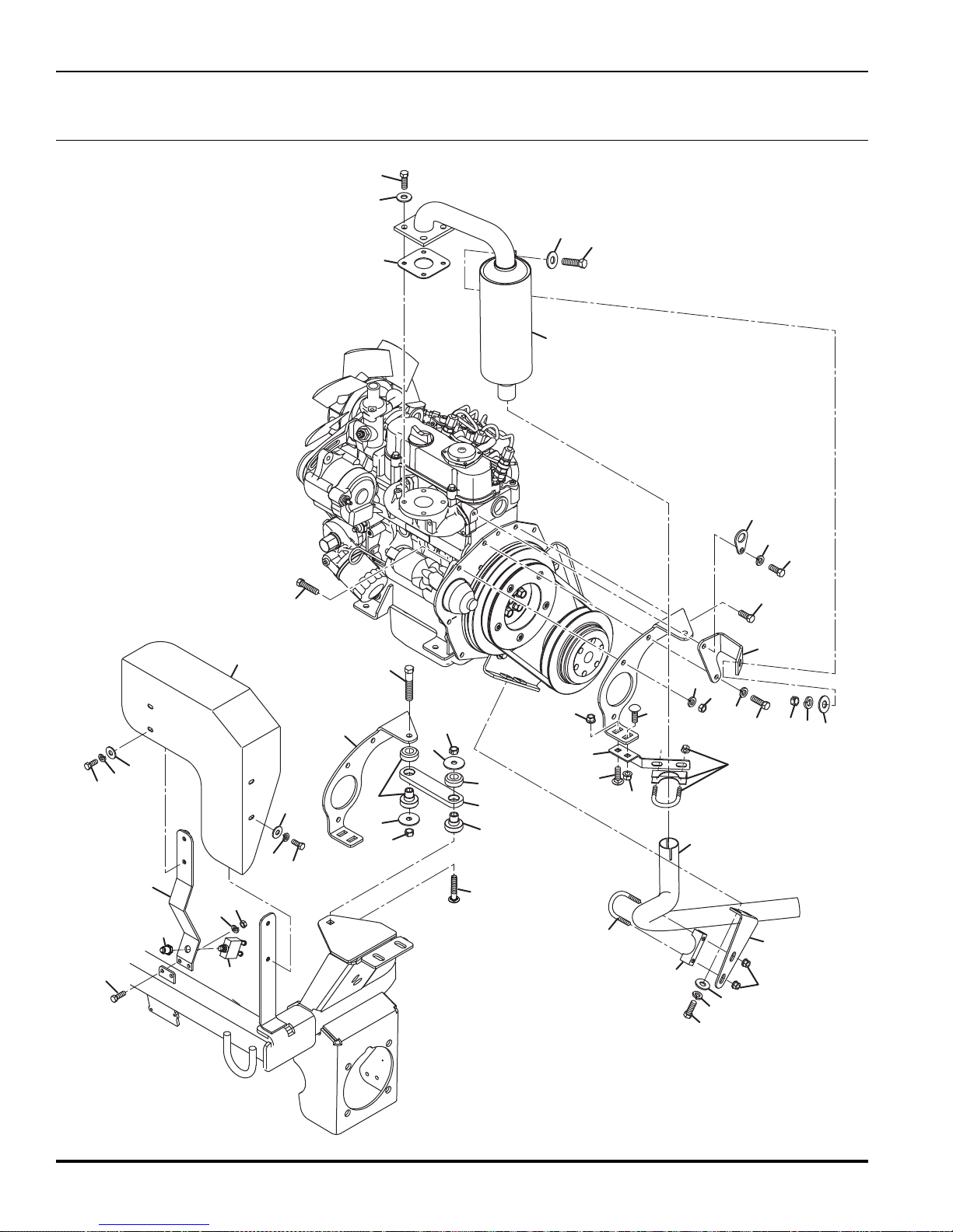
1
2
3
4
4
5
6
6
7
8
9
10
11
11
11
12
13
14
15
16
17
18
19
19
19
19
20
21
21
22
22
23
24
25
26
26
27
27
38
39
27
28
28
29
30
31
32
33
34
34
34
35
35
36
36
36
37
TRI-KING
16.1 Engine Exhaust
Serial No. All
62

TRI-KING
Item Part No. Qty. Description Serial Numbers/Notes
1
● 2 553020 1 Gasket, Muffler
● 3 594331 4 Bolt, Muffler
4 452006 6 Flat Washer, 5/16
5 400264 1 Screw, 3/8-16 x 1-1/4” Hex Head
6 452008 2 Flat Washer, 3/8
7 4121007.7 1 Bracket, Muffler
8 446142 1 Lockwasher, 3/8 Heavy
● 9 550376 1 Bolt
10 363586 1 Screw, M8-1.25 x 20 mm Hex Head
11 446136 10 Lockwasher, 5/16 Heavy
● 12 553934 1 Hook, Engine
13 4130755 1 Bracket, Muffler
14 361005 1 Screw, M8-1.25 x 25 mm Hex Head
● 15 550383 2 Bolt, Starter
● 16 550409 2 Washer, Spring
● 17 550398 2 Nut
18 4123003 1 Pipe, Exhaust
19 1002033 2 Clamp, Exhaust
20 4130753 1 Bracket, Lower Exhaust
21 441602 2 Carriage Bolt, 5/16-18 x 3/4”
22 445795 2 Nut, 5/16-18 Spiralock Flange
23 4130757 1 Bracket, Tailpipe
24 400186 2 Screw, 5/16-18 x 7/8” Hex Head
25 4208820 1 Shield, Muffler
26 400106 4 Screw, 1/4-20 x 5/8” Hex Head
27 446130 6 Lockwasher, 1/4 Heavy
28 452004 4 Flat Washer, 1/4
29 4121872.7 1 Bracket, Heat Shield
30 400108 2 Screw, 1/4-20 x 3/4” Hex Head
31 443102 2 Nut, 1/4-20 Hex
32 4130756 1 Bar, Engine Stay
33 441630 1 Carriage Bolt, 3/8-16 x 2”
34 4124806 2 Mount, Bonded Tube Isolator
35 319755 2 Washer
36 444762 3 Locknut, 3/8-16 Hex Center
37 400270 1 Screw, 3/8-16 x 2” Hex Head
38 3000359 1 Circuit Breaker, 50 Amp REFERENCE CB1, See 42.1
39 364774 1 Boot, Circuit Breaker
4121920 1 Muffler
● Included with Engine
> Change from previous revision
63

1
2
3
4
4
5
6
7
7
7
7
7
8
8
8
8
9
10
11
12
13
14
15
16
TRI-KING
17.1 Fuel Control
Serial No. All
Item Part No. Qty. Description Serial Numbers/Notes
1
2 361898 1 Screw, M8-1.25 x 16 mm Hex Head
3 446136 1 Lockwasher, 5/16 Heavy
4 400112 4 Screw, 1/4-20 x 1” Hex Head
5 3004410 1 Spacer
6 1004340 1 Cable, Throttle See 4.1 For Handle Mounting
7 446130 7 Lockwasher, 1/4 Heavy
8 443102 5 Nut, 1/4-20 Hex
9 400108 1 Screw, 1/4-20 x 7/8” Hex Head
10 444708 1 Locknut, 1/4-20 Hex Center
11 2810088 1 Bracket, Solenoid
12 362535 2 Screw, M6-1 x 16 mm Hex Head
13 453023 2 Flat Washer, 1/4
14 338289 1 Solenoid, Fuel Shutoff REFERENCE K1, See 42.1
15 443104 1 Nut, 1/4-28 Hex
16 2810546 1 Rod, Solenoid
64
2810134 1 Bracket, Throttle Cable
> Change from previous revision

A
B
A
B
View Rotated 180°
For Clarity
1
1
1
1
2
3
4
5
6
7
7
8
9
10
10
18.1 Fuel Hose Routing
TRI-KING
Serial No. All
Item Part No. Qty. Description Serial Numbers/Notes
1
2 554748 AR Hose, 5/16 I.D. Tank to Fuel Filter 10 Foot Length, Cut to 37”
3 550553 1 Filter, Fuel
4 400200 1 Screw, 5/16-18 x 2-1/2” Hex Head
5 444718 1 Locknut, 5/16-18 Hex Center
6 554748 AR Hose, 5/16 I.D. Fuel Filter To Engine 10 Foot Length, Cut to 13”
7 366526 2 Clamp, Hose
8 554752 AR Hose, 3/16 I.D. Fuel Return 10 Fot Length, Cut to 88”
9 3003764 1 Convoluted Conduit, 1/2” I.D. 22”
10 473142 4 Cable Tie
366526 4 Clamp, Hose
550489 1 Element, Fuel Filter
> Change from previous revision
65

1
2
2
3
3
4
4
5
5
6
7
8
22
23
24
9
10
11
12
13
14
15
16
17
18
18
19
20
21
TRI-KING
19.1 Fuel and Hydraulic Tanks
Serial No. All
66

TRI-KING
Item Part No. Qty. Description Serial Numbers/Notes
1
2 400424 4 Screw, 1/2-13 x 4-1/2” Hex Head
3 344132 4 Washer
4 446154 4 Lockwasher, 1/2 Heavy
5 443118 4 Nut, 1/2-13 Hex
6 1000973 1 Bracket, Battery
7 2809688 1 Cap, Tank Breather
8 1001148 1 Filter Assembly
9 549597 1 • Cartridge, Filter
10 N/S 1 Battery, 12V Group 22NF REFERENCE B1, See 42.1
11 346361 2 Hook, 1/4-20 J
12 3003444 1 Retainer, Battery
13 452004 2 Flat Washer, 1/4
14 446130 2 Lockwasher, 1/4 Heavy
15 445612 2 Nut, 1/4-20 Wing
16 1001134 1 Fuel Tank Approximately 6.5 Gallons
17 1001311 1 Fuel Shut Off Valve
18 361117 2 Bushing, Fuel Tank
19 325822 1 Hose, 1/4 x 14” Fuel
20 361748 1 Valve, Overflow
21 4179802 1 Cap, Fuel Tank
22 3002397 1 Plug, -10 ORB Magnetic Drain
23 339899 1 • O-Ring, -10 ORB
24 339900 1 O-Ring, -12 ORB
1002019.6 1 Tank, Hydraulic Oil Approximately 4.5 Gallons
5003624 1 • Gasket
> Change from previous revision
67

1
2
3
3
3
4
5
6
6
7
7
8
9
10
11
12
13
21
22
22
14
15
16
16
16
16
17
18
19
20
20
TRI-KING
20.1 Traction Pump and Charge Filter
Serial No. All
68

TRI-KING
Item Part No. Qty. Description Serial Numbers/Notes
1
2 400272 2 Screw, 3/8-16 x 2-1/4” Hex Head
3 446142 4 Lockwasher, 3/8 Heavy
4 400276 1 Screw, 3/8-16 x 3” Hex Head
5 400274 1 Screw, 3/8-16 x 2-1/2” Hex Head
6 443110 2 Nut, 3/8-16 Hex
7 452008 2 Flat Washer, 3/8
8 3003223 1 Shield, Filter Drain
9 444762 1 Locknut, 3/8-16 Hex Center
10 2810439 1 Bracket, Charge Filter
11 400108 2 Screw, 1/4-20 x 3/4” Hex Head
12 446130 2 Lockwasher, 1/4 Heavy
13 452004 2 Flat Washer, 1/4
14 1001148 1 Charge Filter Assembly
15 400264 1 Screw, 3/8-16 x 1-1/4” Hex Head
16 443810 4 Nut, 3/8-16 Hex Jam
17 463113 1 Key, 3/16 x 3/4” Morton
18 4129588 1 Fan, Pump Cooling
19 4129589 1 Universal Joint See 14.1 For Engine Connection
20 412020 2 Screw, 5/16-18 x 1” Square Head Set
21 361723 1 Stop, Rubber
22 453011 2 Flat Washer, 3/8
4129590 1 Pump, Hydraulic Traction See 37.1
549597 1 • Cartridge, Charge Filter
554663 2 • Cross and Bearing Kit
> Change from previous revision
69

TRI-KING
21.1 Traction Pump Hydraulics
17
Serial No. All
17
2
17
1
15
9
13
16
14
7
8
4
6
3
2
17
5
11
12
12
10
70
9

TRI-KING
Item Part No. Qty. Description Serial Numbers/Notes
1
2 108094-02 2 Clamp, Hose
3 4129590 1 Pump, Hydraulic Traction See 20.1 for Pump Mounting
4 340070 1 Fitting, -10 ORFS x -10 ORB 90°
5 2809725 1 Tube, Traction Pump Return
6 1001503 1 Hose, Traction Pump Return
7 339989 1 Fitting, -10 ORFS x -10 ORB Straight
8 354080 1 Clamp, Hose See 22.1 for Mounting
9 340055 2 Fitting, -4 ORFS x -4 ORB 90°
10 4182425 1
11 4189920 1
12 1001488 2 Hose, Wheel Motor Case Drain
13 1001148 1 Charge Filter Assembly See 20.1 for Filter Mounting
14 340068 1 Fitting, -8 ORFS x -12 ORB 90°
15 1001372 1 Tube, Charge Filter to Pump
16 339983 1 Fitting, -8 ORFS x -6 ORB Straight
17 473142 4 Cable Tie
3003219 1 Hose, Charge Pump Suction
339911 1 • O-Ring, -10 ORFS
339899 1 • O-Ring, -10 ORB
339911 1 • O-Ring, -10 ORFS
339908 2 • O-Ring, -4 ORFS
339911 1 • O-Ring, -10 ORFS
339899 1 • O-Ring, -10 ORB
339908 1 • O-Ring, -4 ORFS
339896 1 • O-Ring, -4 ORB
Wheel Motor, 11.9 in
Wheel Motor, 9.6 in
549597 1 • Cartridge, Charge Filter
339910 1 • O-Ring, -8 ORFS
339900 1 • O-Ring, -12 ORB
339910 2 • O-Ring, -8 ORFS
339897 1 • O-Ring, -6 ORB
3
Front Left
3
Front Right
See 9.1 for Motor Mounting
See 9.1 for Motor Mounting
> Change from previous revision
71

Por t A
Por t B
1
2
2
2
2
2
2
(Port B)
2
(Port B)
2
(Port B)
2
(Port A)
2
(Port A)
3
4
(Port A)
5
6
7
8
9
10
11
12
17
17
17
17
13
14
15
16
Por t A
Por t B
Por t A
Por t B
Motor (10) Viewed from Rear
Motor (6) Viewed from Rear
Motor (15) Viewed from Rear
TRI-KING
22.1 Traction Hydraulics
Serial No. All
72

TRI-KING
Item Part No. Qty. Description Serial Numbers/Notes
1
2 339989 11 Fitting, -10 ORFS x -10 ORB Straight
3 2810603 1 Tube, Pump to Upper Motor Port
4 340265 1 Tee, -10 ORFS x -10 ORB Run
5 2810602 1 Tube, Upper Motor Ports
6 4182425 1
7 1001495 1 Hose, Upper Tube to 3WD Valve
8 4111942 1 3WD Valve See 10.1 For Valve Mounting
9 1001496 1 Hose, 3WD Valve to Motor Wheel Motor Port (A)
10 4182425 1
11 1001496 1 Hose, Motor to 3WD Valve Wheel Motor Port (B)
12 1001495 1 Hose, 3WD Valve to Lower Tube
13 2810601 1 Tube, Lower Motor Ports
14 340121 1 Tee, -10 ORFS Swivel Run
15 4189920 1
16 2810604 1 Tube, Lower Motor Port to Pump
17 473142 3 Cable Tie
4129590 1 Pump, Hydraulic Traction See 20.1 For Pump Mounting
339911 1 • O-Ring, -10 ORFS
339899 1 • O-Ring, -10 ORB
339911 2 • O-Ring, -10 ORFS
339899 1 • O-Ring, -10 ORB
Wheel Motor, 11.9 in
Wheel Motor, 11.9 in
339911 2 • O-Ring, -10 ORFS
Wheel Motor, 9.6 in
3
3
Front Left
3
Rear
Front Right
See 9.1 For Motor Mounting
See 11.1 For Motor Mounting
See 9.1 For Motor Mounting
> Change from previous revision
73

R
L
P
T
E
1
2
2
2
2
3
4
5
6
7
8
9
10
11
12
12
13
14
22
22
22
22
15
16
17
18
19
20
21
Item 5
Item 3
Item 6
Item 11
Item 14
Part of
Frame
23
24
25
26
27
TRI-KING
23.1 Steering and Lift Hydraulics
Serial No. All
74

TRI-KING
Item Part No. Qty. Description Serial Numbers/Notes
1
2 340061 5 Fitting, -6 ORFS x -6 ORB 90°
3 4223520 1 Tube, Pump to Steering Valve Steering Valve Port P
4 4196485 1 Valve, Steering See 20.1 for Valve Mounting
5 4218141 1 Hose, Steering Valve to Lift Valve Steering Port Port E
6 4203100 1 Tube, Steering Valve to Charge Filter Steering Valve Port T
7 340120 1 Tee, -8 ORFS Swivel Run
8 340068 1 Fitting, -8 ORFS x -12 ORB 90°
9 1001148 1 Charge Filter Assembly See 20.1 for Filter Mounting
10 1001500 1 Hose, Lift Valve to Charge Filter
11 1002942 1 Hose, Steering Valve to Cylinder Steering Valve Port L
12 340057 2 Fitting, -4 ORFS x -6 ORB 90°
13 4138501 1 Steering Cylinder See 11.1 for Cylinder Mounting
14 1002941 1 Hose, Steering Valve to Cylinder Steering Valve Port R
15 354080 1 Clamp, Hose See 9.1 for clamp mounting
16 4240904 1 Lift Valve
17 340088 1 Fitting, -4 ORFS x -6 ORB 90° Orifice 0.0595 Orifice
18 1001501 1 Hose, Lift Valve to Cylinder
19 122759 1 Cylinder, Hydraulic Lift See 28.1 for Cylinder Mounting
20 1001502 1 Hose, Cylinder to Lift Valve
21 339974 1 Fitting, -4 ORFS x -6 ORB Orifice
22 473142 4 Cable Tie
23 400188 1 Screw, 5/16-18 x 1” Hex Head
24 452006 1 Flat Washer, 5/16
25 361064 1 Clamp, Hose
26 446136 1 Lockwasher, 5/16 Heavy
27 443106 1 Nut, 5/16-18 Hex
4129590 1 Pump, Hydraulic Traction See 20.1 for Pump Mounting
339909 1 • O-Ring, -6 ORFS
339897 1 • O-Ring, -6 ORB
4197940 1 • Seal Kit
339910 2 • O-Ring, -8 ORFS
339910 1 • O-Ring, -8 ORFS
339900 1 • O-Ring, -12 ORB
549597 1 • Cartridge, Charge Filter
339908 1 • O-Ring, -4 ORFS
339897 1 • O-Ring, -6 ORB
4137139 1 • Seal Kit
4240905 1 • Seal Kit
339908 1 • O-Ring, -4 ORFS
339897 1 • O-Ring, -6 ORB
554331 1 • Seal Kit
339908 1 • O-Ring, -4 ORFS
339897 1 • O-Ring, -6 ORB
> Change from previous revision
75

1
1
1
1
2
3
4
5
6
Part of
Frame
7
8
9
9
10
11
12
13
14
15
16
17
TRI-KING
24.1 Gear Pump Hydraulics
Serial No. All
76

TRI-KING
Item Part No. Qty. Description Serial Numbers/Notes
1
2 3003113 1 Hose, Suction
3 3003115 1 Tube, Gear Pump Suction
4 354080 1 Clamp, Hose See 9.1
5 3003114 1 Hose, Formed Suction
6 4174020 1 Pump, 3 Section Gear See 15.1
7 1001147 1 Tube, Reel Motor Return
8 345671 1 Clamp, Hose See 10.1
9 108094-02 2 Clamp, Hose
10 3003218 1 Hose
11 3003256 1 Fitting, -12 ORB Beaded Tube
12 3004182 1 Angle, Bulkhead
13 339963 1 Nut, -10 ORFS Bulkhead
14 400188 1 Screw, 5/16-18 x 1” Hex Head
15 452006 1 Flat Washer, 5/16
16 446136 1 Lockwasher, 5/16 Heavy
17 443106 1 Nut, 5/16-18 Hex
367458 4 Clamp, Hose
339900 1 • O-Ring, -12 ORB
> Change from previous revision
77

TRI-KING
25.1 Reel Hydraulics
Serial No. All
14
10
7
4
6
15
6
13
4
5
6
12
6
9
8
11
13
6
5
3
1
8
2
6
6
78
10
8
7
3
12
6

TRI-KING
Item Part No. Qty. Description Serial Numbers/Notes
1
2 339979 3 Fitting, -6 ORFS x -6 ORB Straight
3 1001492 1 Hose, Pump to Left Motor Pump Section 1
4 1001493 1 Hose, Pump to Center Motor Pump Section 2
5 1001494 1 Hose, Pump to RIght Motor Pump Section 3
6 473142 8 Cable Tie
7 339980 2 Fitting, -6 ORFS x -8 ORB
8 1002603 3 Motor, Reel
9 340062 1 Fitting, -6 ORFS x -8 ORB 90°
10 340070 2 Fitting, -10 ORFS x -10 ORB 90°
11 339989 1 Fitting, -10 ORFS x -10 ORB Straight
12 1001489 1 Hose, Left Motor to Return Tube
13 1001490 1 Hose, Right Motor to Return Tube
14 1001491 1 Hose, Center Motor to Return Tube
15 1001147 1 Tube, Reel Return See 24.1
4174020 1 Pump, 3 Section Gear See 15.1
339909 1 • O-Ring, -6 ORFS
339897 1 • O-Ring, -6 ORB
339909 1 • O-Ring, -6 ORFS
339898 1 • O-Ring, -6 ORB
339909 1 • O-Ring, -6 ORFS
339898 1 • O-Ring, -6 ORB
339911 1 • O-Ring, -10 ORFS
339899 1 • O-Ring, -10 ORB
339911 1 • O-Ring, -10 ORFS
339899 1 • O-Ring, -10 ORB
> Change from previous revision
79

1
2
3
4
4
4
4
4
4
4
5
5
5
5
5
5
6
6
4
10
11
12
12
13
13
13
Center Reel
14
14
16
15
7
7
8
9
TRI-KING
26.1 Hydraulic Tube Clamps
Serial No. All
Item Part No. Qty. Description Serial Numbers/Notes
1
2 441668 2 Carriage Bolt, 1/4-20 x 1-1/4”
3 3004410 2 Spacer
4 452004 8 Flat Washer, 1/4
5 444708 10 Locknut, 1/4-20 Hex Center
6 3003110 2 Clamp, Double Tube
7 400116 2 Screw, 1/4-20 x 1-1/2” Hex Head
8 364221 1 Clamp, Double Tube
9 400114 1 Screw, 1/4-20 x 1-1/4” Hex Head
10 3003665 1 Stud, 1/4-20 x 2-3/4”
11 446130 1 Lockwasher, 1/4 Heavy
12 443102 3 Nut, 1/4-20 Hex
13 3003473 4 Clamp, Double Hose
14 400120 3 Screw, 1/4-20 x 2” Hex Head
15 400108 2 Screw, 1/4-20 x 3/4” Hex Head
16 3003323 1 Bracket, Center Reel Hose Clamp
80
3003242 1 Bracket, Tube Clamp
> Change from previous revision

1
2
3
4
5
6
7
7
12
16
17
13
14
15
6
8
9
10
11
27.1 Electrical Routing
TRI-KING
Serial No. All
Item Part No. Qty. Description Serial Numbers/Notes
1
2 3003523 1 Cable, Negative Battery
3 3004539 1 Convoluted Conduit
4 400112 1 Screw, 1/4-20 x 1” Hex Head
5 447010 1 Lockwasher, 1/4 External Tooth
6 443102 3 Nut, 1/4-20 Hex
7 1004795 1 Wire Harness, Main
8 400108 2 Screw, 1/4-20 x 3/4” Hex Head
9 452004 2 Flat Washer, 1/4
10 345671 2 Clamp, Harness
11 446128 2 Lockwasher, 1/4
12 403912 1 Screw, #10-24 x 5/8” Truss Head
13 447006 1 Lockwasher, #10 External Tooth
14 446118 1 Lockwasher, #10 Heavy
15 444310 1 Nut, #10-24 Hex
16 3001307 2 Relay, SPDT with Resistor REFERENCE K4 and K5, See 42.1
17 2811632 1 Harness, Brake Light
2810624 1 Cable, Positive Battery
> Change from previous revision
81

1
2
3
4
4
5
6
7
8
9
9
10
11
12
13
14
15
16
17
17
18
19
20
21
22
23
24
25
26
27
28
29
29
30
31
31
32
33
34
35
36
37
38
TRI-KING
28.1 Lift Cylinder Linkage
Serial No. All
82

TRI-KING
Item Part No. Qty. Description Serial Numbers/Notes
1
2 554330 1 • Bushing, Bronze
3 364238 1 Pin, Cylinder
4 345700 6 Washer, Shim
5 460052 1 Cotter Pin, 3/16 x 1-1/2
6 1001258.7 1 Crank Bottom
7 307374 1 Washer
8 458038 1 Retaining Ring
9 365106 2 Bushing, Lift Crank Included with Frame
10 463040 1 Key, 1/4 x 1-1/4” Woodruff
11 1001259.7 1 Crank Top
12 415519 1 Set Screw, 5/16-18 x 3/8”
13 3003035 1 Pin, Transport Lock
14 461418 1 Roll Pin, 1/4 x 3-1/2”
15 460335 1 Pin, 1/8 Spring Clip
16 1001271.7 1 Rear Lift Arm
17 3007694 2 • Bushing
18 471216 1 Grease Fitting, Straight
19 2809741 1 Pin, Pivot
20 460096 1 Cotter Pin, 5/16 x 1-3/4”
21 400188 1 Screw, 5/16-18 x 1” Hex Head
22 446136 1 Lockwasher, 5/16 Heavy
23 452006 1 Flat Washer, 5/16
24 443106 1 Nut, 5/16-18 Hex
25 364234 1 Ball Joint, Rod End
26 444780 1 Locknut, 1/2-20 Hex Center
27 443820 1 Nut, 1/2-20 Hex Jam
28 1000956.7 1 Chain, Lift
29 3001905.7 2 Plate
30 3006409 2 Screw, 3/8-16 x 1-1/2” Gr 8 Hex Head
31 452006 2 Flat Washer
32 445799 2 Locknut, 3/8-16 Hex Center For Grade 8 Bolt
33 364149.7 1 Spring, Extension
34 400262 1 Screw, 3/8-16 x 1” Hex Head
35 446142 1 Lockwasher, 3/8 Heavy
36 452008 1 Flat Washer, 3/8
37 3003754 1 Bolt, 3/8-16 Spring
38 443110 2 Nut, 3/8-16 Hex
122759 1 Cylinder, Hydraulic Lift
554331 1 • Seal Kit
> Change from previous revision
83

TRI-KING
29.1 Reel Assembly
Serial No. All
22
21
40
20
17
5
25
30” Reel
Lift Arms
40
19
18
2
4
4
29
5
7
27
28
26
3
33 / 34
37
32
36
31
8
38
9
30
39
8
2
7
3
18
3
2
1
1
35
2
3
17
16
23
24
21
15
84
11
14
4
13
5
11
12
6
10

TRI-KING
Item Part No. Qty. Description Serial Numbers/Notes
1
2 400272 AR Screw, 3/8-16 x 2-1/4” Hex Head
3 444762 AR Locknut, 3/8-16 Hex Center
4 1002603 3 Motor, Reel See 36.1
5 2810171 3 Snap Ring
6 67114 1 26” 7 Blade Left Reel Assembly
6 67123 1 30” 7 Blade Left Reel Assembly Includes Items 2, 3, and 40
7 2811281 1 • Lift Arm, Left Side 26” Reel Used with 67114, Includes Decal
7 2811279 1 • Lift Arm, Left Side 30” Reel Used with 67123, Includes 2, 3, 40
8 3007694 2 • • Bushing
9 471214 1 • Grease FItting, 1/4-28 Straight
10 364781 1 • Washer, Retaining
11 446142 3 • Lockwasher, 3/8 Heavy
12 400260 1 • Screw, 3/8-16 x 7/8” Hex Head
13 364777 1 • Gasket, Motor
14 453011 2 • Flat Washer, 3/8
15 443110 2 • Nut, 3/8-16 Hex
16 67115 1 26” 7 Blade Right Reel Assembly
16 67124 1 30” 7 Blade Right Reel Assembly Includes Items 2, 3, and 40
17 2811280 1 • Lift Arm, Right Side 26” Reel Used with 67115, Includes Decal
17 2811278 1 • Lift Arm, Right Side 30” Reel Used with 67124, Includes 2, 3, 40
18 3007694 2 • • Bushing
19 471214 1 • Grease FItting, 1/4-28 Straight
20 364781 1 • Washer, Retaining
21 446142 3 • Lockwasher, 3/8 Heavy
22 400260 1 • Screw, 3/8-16 x 7/8” Hex Head
23 364777 1 • Gasket, Motor
24 453011 2 • Flat Washer, 3/8
25 443110 2 • Nut, 3/8-16 Hex
26 67116 1 26” 7 Blade Center Reel Assembly
26 67125 1 30” 7 Blade Center Reel Assembly
27 3002718 1 • Collar
28 3005435 1 • Pin, Spring Lock
29 364777 1 • Gasket, Motor
30 453011 2 • Flat Washer, 3/8
31 446142 2 • Lockwasher, 3/8 Heavy
32 443110 2 • Nut, 3/8-16 Hex
33 5000183 1 Limit Switch REFERENCE SW4, See 42.1
34 5000184 1 Operator Head
35 3001078 1 Actuator Head
36 364694 1 Cable Connector
37 402132 2 Screw, #10-24 x 1-3/4” Slotted Round
38 446118 2 Lockwasher, #10
39 444310 2 Nut, #10-24 Hex
40 3003041 2 Shaft, Lift Arm Used with 67123 and 67124
3002430 2 Pin, Lift Arm
> Change from previous revision
85

5 Blade Reel (Optional)
7 Blade Reel (Standard)
10 Blade Reel (Optional)
26 in. (660 mm) Reels30 in. (762 mm) Reels
67114 67116 67115 67123 67126 67125
2500712
5002087
2500714
Left Center Right Left Center Right
2500712
5002087
2500714
2500713
5002088
2500715
503359
5002089
503361
503359
5002089
503361
503360
5002090
503362
Number of
Reel Blades
1
2
3
4
5
6
7
8
9
10
11
11
12
12
13
13
14
14
15
15
16
16
17
17
18
19
20
21
22
23
24
25
26
27
28
29
30
31
32
33
33
34
34
35
35
18
31
32
TRI-KING
30.1 Inner Reel Assembly
Left and Center Reel Shown, Right Opposite.
Serial No. 67114 - All
Serial No. 67115 - All
Serial No. 67116 - All
Serial No. 67123 - All
Serial No. 67124 - All
Serial No. 67125 - All
86

TRI-KING
Item Part No. Qty. Description Serial Numbers/Notes
1
1 1001642 1 30” Reel Mower Frame Used on 67123, 67124, and 67125
2 5001607 1 Bearing Housing, Reel Motor
3 3001152 1 • Washer
4 3000983 1 • Oil Seal
5 471214 1 • Grease Fitting, 1/4-28 Straight
6 500596 1 • Bearing, Cup and Cone
7 471242 1 • Relief Fitting, 1/8 NPTF Grease
8 3003086 2 • Stud, 3/8-16 x 5/8”
9 364148 1 Spring, Compression
10 458039 1 Snap Ring
11 3003517 2 Shoulder Bolt, 3/4-16 Special
12 306828 2 Washer
13 3004370 2 Locknut, 3/4-16 Thin Security
14 434031 2 Screw, 1/4-20 x 3/4” Hex Socket Head
15 400446 2 Screw, 1/2-20 x 2” Hex Head
16 3003389 2 Bushing, Housing Pivot
17 364151 2 Washer, Wave
18 445789 2 Nut, 1/2-20 Spiralock Flange
19 503684 1 Coupler, Motor
20 5001606 1 Bearing Housing
21 3001152 1 • Washer
22 3000983 1 • Oil Seal
23 500596 1 • Bearing, Cup and Cone
24 471214 1 • Grease Fitting, 1/4-28 Straight
25 471242 1 • Relief Fitting, 1/8 NPTF Grease
26 See Chart 1 Reel
27 364283 1 Spacer, Tube
28 364259 1 Washer, Bearing Retainer
29 400264 1 Screw, 3/8-16 x 1-1/4” Hex Head
30 446142 1 Lockwasher, 3/8 Heavy
31 3003611 2 Nut, Reel Adjuster
32 472519 2 Plug
33 365995 2 Washer, Spherical
34 445718 2 Locknut, 5/8-18 Hex Stover
35 3004189 2 Screw, Reel Adjuster
1001643 1 26” Reel Mower Frame Used on 67114, 67115, and 67116
> Change from previous revision
87

TRI-KING
31.1 Outer Reel
Serial No. 67114 - All
Serial No. 67115 - All
Serial No. 67116 - All
Serial No. 67123 - All
Serial No. 67124 - All
Serial No. 67125 - All
23
19
25
20
22
3
21
22
22
4182520
22
67114
67115
67116
24
23
22
23
67123
14
67124
18
67125
17
1
3
2
16
9
15
4
6
13
5
7
8
3
2
11
10
12
88

TRI-KING
Item Part No. Qty. Description Serial Numbers/Notes
1
2 400258 6 Screw, 3/8-16 x 3/4” Hex Head
3 446142 8 Lockwasher, 3/8 Heavy
4 364282 1 Plate, Support
5 3005890 4 Wheel Bolt, 3/8-16
6 5000616 1 Bedkinfe Backing, 26” Used on 67114, 67115, 67116
6 5000617 1 Bedknife Backing, 30” Used on 67123, 67124, 67125
7 554284 1 Bedknife, 26” Used on 67114, 67115, 67116
7 503550 1 Bedknife, 30” Used on 67123, 67124, 67125
8 3007308 11 Screw, 3/8-24 x 3/4” Flat Head Used on 67114, 67115, 67116
8 3007308 13 Screw, 3/8-24 x 3/4” Flat Head Used on 67123, 67124, 67125
9 4184653 11 Locknut, 3/8-24 Expanding Used on 67114, 67115, 67116
9 4184653 13 Locknut, 3/8-24 Expanding Used on 67123, 67124, 67125
10 338585 1 Cover, Bearing Housing
11 364147 1 Gasket, Cover
12 434038 4 Screw, #10-24 x 1/2” Truss Head
13 446116 4 Lockwasher, #10
14 122875.6 1 Rear Shield Used on 67114 and 67115
14 1003056.6 1 Rear Shield Used on 67116
14 122769.6 1 Rear Shield Used on 67123 and 67124
14 1003057.6 1 Rear Shield Used on 67125
15 400186 4 Screw, 5/16-18 x 7/8” Hex Head
16 446136 4 Lockwasher, 5/16 Heavy
17 3000718 AR Shim, Shield
18 364281 2 Backup Nut, 5/16-18
19 443110 2 Nut, 3/8-16 Hex
20 364150 1 Clamp, Tube
21 5003650 1 Shield, 26” Reel Used on 67114, 67115, 67116
21 5003648 1 Shield, 30” Reel Used on 67123, 67124, 67125
22 4182520 4 • Decal, Shield
23 3002379 2 • Decal, Tight
24 400260 2 Screw, 3/8-16 x 7/8” Hex Head
25 453011 2 Flat Washer, 3/8
REF 1 Inner Reel See 30.1
> Change from previous revision
89

TRI-KING
32.1 Pivot Arms
20
Serial No. 67114 - All
Serial No. 67115 - All
Serial No. 67116 - All
23
Serial No. 67123 - All
Serial No. 67124 - All
Serial No. 67125 - All
4
4
20
16
22
21
21
1
18
19
19
18
21
2
21
14
13
17
23
9
10
11
10
13
2
3
17
7
8
13
13
14
10
11
10
6
12
8
15
9
90
12
5
15
8
7
8

TRI-KING
Item Part No. Qty. Description Serial Numbers/Notes
1
1 4113756 1 30” Center Pivot Arm Used on 67125
2 364140 2 • Bushing
3 4113758 1 26” Left Pivot Arm Used on 67114
3 4113757 1 26” Right Pivot Arm Used on 67115
3 4113755 1 30” Left Pivot Arm Used on 67123
3 4113754 1 30” Right Pivot Arm Used on 67124
4 364156 2 • Bushing
5 338561 1 Pivot Bracket, Left Side
6 338562 1 Pivot Bracket, RIght Side
7 400260 4 Screw, 3/8-16 x 7/8” Hex Head
8 446142 4 Lockwasher, 3/8 Heavy
9 400442 2 Screw, 1/2-20 x 1-1/2” Hex Head
10 452012 4 Flat Washer, 1/2
11 366827 2 Spacer, Pivot
12 445789 2 Nut, 1/2-20 Spiralock Flange
13 453011 6 Flat Washer, 3/8
14 400264 2 Screw, 3/8-16 x 1-1/4” Hex Head
15 443110 2 Nut, 3/8-16 Hex
16 3002813 1 Bracket, Left Side Reel Bumper Used on 67116 and 67125 Only
17 400190 4 Screw, 5/16-18 x 1-1/4” Hex Head Used on 67116 and 67125 Only
18 446136 4 Lockwasher, 5/16 Heavy Used on 67116 and 67125 Only
19 443106 4 Nut, 5/16-18 Hex Used on 67116 and 67125 Only
20 361723 2 Rubber Bumper Used on 67116 and 67125 Only
21 443810 4 Nut, 3/8-16 Hex Jam Used on 67116 and 67125 Only
22 3002814 1 Bracket, Right Side Reel Bumper Used on 67116 and 67125 Only
23 471214 1 Grease FItting
4113759 1 26” Center Pivot Arm Used on 67116
> Change from previous revision
91

1 / 2
3
4
4
5
5
6
6
7
7
8
8
9
9
10
10
10
10
11
11
12
12
13
13
13
13
14
14
14
14
15
15
15
15
15
15
16
16
16
16
16
17
18
19
19
20
21
21
21
21
22
22
22
22
23
24
25
24
TRI-KING
33.1 Roller Brackets and Skids
Serial No. 67114 - All
Serial No. 67115 - All
Serial No. 67116 - All
Serial No. 67123 - All
Serial No. 67124 - All
Serial No. 67125 - All
92

TRI-KING
Item Part No. Qty. Description Serial Numbers/Notes
1
1 132640 1 Roller, 30” Reel Rear Used on 67123, 67124, and 67125
2 5002831 1 • Tube, 26” Reel Roller Used on 67114, 67115, and 67116
2 5002832 1 • Tube, 30” Reel Roller Used on 67123, 67124, and 67125
3 3003415 1 • Shaft, 26” Reel Roller Used on 67114, 67115, and 67116
3 3003414 1 • Shaft, 30” Reel Roller Used on 67123, 67124, and 67125
4 338647 2 • Seal, Inner Oil
5 500534 2 • Bearing, Cup and Cone
6 3005156 2 • Wear Sleeve
7 3004882 2 • Seal, Outer Oil
8 367029 2 • Locknut, 3/4-16 Hex Jam
9 471214 2 • Grease Fitting, 1/4-28 Straight
10 132680 2 Rear Roller Adjuster
11 412015 2 Set Screw, 5/16-18 x 5/8” Square Hd
12 3007673 2 Housing, Roller Adjuster
13 3000313 4 Nut, 3/4-16 Hex Adjuster
14 400264 8 Screw, 3/8-16 x 1-1/4” Hex Head
15 446142 8 Lockwasher, 3/8 Heavy
16 443110 8 Nut, 3/8-16 Hex
17 3008359 1 Bracket, Left Side Front Roller
18 3008360 1 Bracket, Right Side Front Roller
19 366653 2 Washer
20 207474 1 Shoe, Left Side Reel Skid
21 434002 4 Screw, 3/4-16 x 1-1/2” Hex Socket
22 446174 4 Lockwasher, 3/4 Light
23 554723 1 Wrench, 5/8” Hex Skid Shoe
24 471214 2 Grease Fitting, 1/4-28 Straight
25 207473 1 Shoe, Right Side Reel Skid
132639 1 Roller, 26” Reel Rear Used on 67114, 67115, and 67116
> Change from previous revision
93

TRI-KING
34.1 Down Pressure Springs
26” Reel
Serial No. 67114 - All
Serial No. 67115 - All
Serial No. 67116 - All
8
9
10
11
12
9
10
13
Serial No. 67123 - All
Serial No. 67124 - All
Serial No. 67125 - All
12
14
30” Reel
13
14
6
7
4
16
5
3
4
4
13
13
12
12
10
11
9
10
9
8
5
4
2
9
10
16
17
17
12
13
12
13
14
14
15
14
13
14
12
4
8
5
4
16
4
13
12
17
9
10
16
11
6
7
2
5
4
3
17
16
1
11
3
7
6
16
10
9
10
9
94
8
7
3
6
1

TRI-KING
Item Part No. Qty. Description Serial Numbers/Notes
1
1 2811279 1 Lift Arm, Left Side 30” Reel Used with 67123, See 29.1
2 2811280 1 Lift Arm, Right Side 26” Reel Used with 67115, See 29.1
2 2811278 1 Lift Arm, Right Side 30” Reel Used with 67124, See 29.1
3 4181863 1 • Decal, Read Manual for Service
4 1001854 4 Shackle, Chain
5 3004065 2 Lift Chain
6 441904 2 Screw, 1/2-13 x 10” Hex Head Full Thread
7 452012 2 Flat Washer, 1/2
8 443118 2 Nut, 1/2-13 Hex
9 400262 4 Screw, 3/8-16 x 1” Hex Head Used with 67114 and 67115
9 401213 6 Screw, 3/8-16 x 4-1/2” Hex Head Used with 67123 and 67124
10 446142 4 Lockwasher, 3/8 Heavy Used with 67114 and 67115
10 446142 6 Lockwasher, 3/8 Heavy Used with 67123 and 67124
11 2811128 2 Plate, Spring Mounting Used with 67114 and 67115
11 2811127 2 Plate, Spring Mounting Used with 67123 and 67124
12 3007908 4 Plug, Spring Used with 67114 and 67115
12 3007908 6 Plug, Spring Used with 67123 and 67124
13 364157 4 Spring, Down Pressure Used with 67114 and 67115
13 364157 6 Spring, Down Pressure Used with 67123 and 67124
14 364160 4 Shackle, Spring Used with 67114 and 67115
14 364160 6 Shackle, Spring Used with 67123 and 67124
15 3005219 2 Bracket, Spring Used with 67123 and 67124 Only
16 452008 6 Flat Washer, 3/8 Used with 67123 and 67124 Only
17 443110 6 Nut, 3/8-16 Hex Used with 67123 and 67124 Only
2811281 1 Lift Arm, Left Side 26” Reel Used with 67114, See 29.1
> Change from previous revision
95

TRI-KING
35.1 Reel Pump
Part No. 4174020
Serial No. All
10
10
13
14
10
8
16
1
10
7
14
10
4
8
8
4
17
10
9
10
19
10
14
10
8
16
17
8
9
18
96
10
4
8
4
16
17
3
3
9
11
3
2
6
10
10
12
15
5

TRI-KING
Item Part No. Qty. Description Serial Numbers/Notes
1
2 N/S 1 Ball, Steel
● 3 N/S 3 Shear Pin
● 4 5001442 4 Snap Ring
● 5 N/S 1 Oil Seal
6 5001435 1 Driveshaft
7 5001444 1 Plug, Lee
8 N/S 6 Gear, 7/16” Wide
● 9N/S3Seal Plate
10 5001446 12 Sleeve, Bearing
11 N/S 1 Idler Shaft
12 N/S 1 Stator
13 N/S 8 Screw, 1/4-20
14 5001449 6 Pin, Alignment
15 5001437 1 Drive Key
● 16 N/S 3 Wear Plate
● 17 N/S 3 O-Ring, Diamond
18 N/S 1 Gear Housing, Section 1
19 N/S 1 Gear Housing, Section 2
N/S 1 Gear Housing, Section 3
5001436 1 Repair Kit Includes Items marked O
0.226 in
3
/rev
> Change from previous revision
97

1
2
3
4
5
5
5
5
6
7
8
9
10
10
10
10
11
11
12
13
14
15
16
17
18
19
20
21
22
23
32
24
25
26
27
28
29
30
31
TRI-KING
36.1 Reel Motor
Part No. 1002603
Serial No. All
98

TRI-KING
Item Part No. Qty. Description Serial Numbers/Notes
1
2 5001443 1 Drive Shaft
● 3 N/S 1 Oil Seal
● 4 N/S 1 Retaining Ring
5 5001446 4 Sleeve, Bearing
● 6 N/S 1 Gasket, 0.00050 (Silver)
● 6 N/S 1 Gasket, 0.00100 (Amber)
● 6 N/S 1 Gasket, 0.00075 (Gold)
7 5001447 1 Idler Shaft
8 N/S 1 Steel Ball
9 5001441 1 Shear Pin
10 5001442 4 Snap Ring
11 5001445 2 Gear, 1-3/8” Wide
12 N/S 1 Housing, Gear
13 5001444 1 Lee Plug
14 5001449 2 Alignment Pin
15 N/S 1 Dowel Bushing
16 555828 1 Screw, 1/4-20
17 N/S 1 Housing, Valve
● 18 N/S 1 O-Ring
19 2501165 1 Valve Plate
● 20 N/S 1 O-Ring
21 N/S 1 • Valve Stem
22 N/S 1 • Shear Pin
● 23 N/S 1 • O-Ring
24 N/S 1 Roll Pin
25 N/S 1 Plug, 1/16 NPTF
26 N/S 7 Screw, 1/4-20
27 N/S 1 ••Cap
● 28 N/S 1 • • Copper Gasket
29 N/S 1 • Adjustment Screw
30 N/S 1 • Spring
31 N/S 1 • Poppet
● 32 N/S 1 O-Ring
5001448 1 Stator
503504 1 Valve Stem Kit
503503 1 Relief Valve Kit
503502 1 • Relief Valve Cap
Use gasket same color as original
gasket.
5002657 1 Seal Kit Includes Items marked ●
> Change from previous revision
99

1
2
3
3
4
5
6
7
8
9
10
10
11
12
13
13
14
15
16
16
17
18
19
20
21
22
23
24
25
26
27
28
28
29
30
31
32
33
34
35
36
37
38
39
40
41
42
43
44
45
TRI-KING
37.1 Traction Pump
Part No. 4129590
Serial No. All
100
 Loading...