

Page 1

1
Page 2

2
Page 3

TABLE OF CONTENTS PAGE
Introduction 4
Safety Precautions 5
Parts Photos 6
Standard Parts List 7
Standard Bolts List 7
Optional Heater Parts List 8
Electrical Connectors List 8
Optional Heater Installation 21
Decals Page 22
Hardware Tightening Torques 23
Operator’s Manual 20
3
Page 4

INTRODUCTION
TO THE PURCHASER
All products are designed to give safe, dependable service if they are operated
and maintained according to instructions. Read and understand this manual
before operation.
This manual has been prepared to assist the owner and operators in the safe
operation and suitable maintenance of the ca nopy. The information is applicable
to products at the time of manufac ture and does not include modifications made
afterwards.
Read and understand this manual before attempting to put equipment into
service. Familiarize yourself with the operating instructions and all the safety
recommendations contained in this manual and those labeled on the equipment
and on the tractor. Follow the safety recommendations and make sure that those
with whom you work follow them.
Illustrations
The illustrations may not necessarily reproduce the full detail and the exact
shape of the parts or depict the actual models, but are intended for reference
only.
Direction Reference
All references to right and left, forward or rearward, are from the operator’s seat,
facing the steering wheel.
Safety Precautions
All products are designed to give safe, dependable service if they are operated
and maintained according to instructions. Read and understand this manual
before operatio n. It is the owner’s responsibility to be certain anyone operating
this product reads this manual, and all other applicable manuals, to become
familiar with this canopy and all safety precautions. Failure to do so could result
in serious personal injury or ca nopy damage. If you have any questions, consult
your dealer.
To assist your dealer in handling your needs, please record hereafter the model
number and serial number of your canopy and tractor. It is also advisable to
supply them to your insurance company. It will be helpful in the event that the
canopy or tractor is lost or stolen.
TRACTOR CA NOPY
MODEL: __________________ ___________________________________________________
SERIAL NUMBER: _____________________________________________________________
DATE OF PURCHASE: _________________________________________________________
DEALER NAME: _______________________________________________________________
4
Page 5

SAFETY PRECAUTIONS
SAFETY FIRST
This symbol, the industry’s “Safety Alert Symbol”, is used throughout this manual
and on labels on the machine itself to warn of the possibility of personal injury.
Read these instructions carefully. It is essential tha t you read the instructions and
safety regulations before you attempt to assemble or use this cab.
DANGER: Indicates an immediate hazardous situation which, if not
avoided, could result in death or serious injury.
WARNING: Indicates a potentially hazardous situation which, if not
avoided, may result in death or serious injury.
CAUTION: Indicates a potentially hazardous situation which, if not
avoided, may result in minor or moderate injury.
IMPORTANT: Indicates that the cab or property damage could result if
instructions are not followed.
NOTE: Gives helpful information.
All products are designed to give safe, dependable service if they are operated
and maintained according to instructions. Read and understand this manual
before installation or operatio n. It is the owner’s responsibility to be certain
anyone operating this product reads this manual, and all other applicable
manuals, to become familiar with this cab and all safety precautions. Failure to
do so could result in serious personal injury or cab damage. If you have any
questions, consult your dealer.
5
Page 6

STANDARD PARTS LIST
QUANTITY SIZE and ITEM
L&R Rear Mounting Brackets (2 piece)
One Front Mounting Bracket
One Rear Panel
One Platform Floormat
L&R Underseat Floormat
Standard Acoustic Foam
One Step Pad
One Hydraulic Pedal Bracket
15’ 180° O-Rubber
Four Structural Washer
One 50 Amp Circuit Breaker (#30055-50 w/jumper wire installed)
One Seat Belt Assembly (#C6180AS)
One 1/4” Yellow Loop
One 1/2” Yellow Loop
30” 3/4” X 3/4” NDAX
32” 1” X 1” NDAX
36” 1/2” X 3/4” NDAX
STANDARD BOLTS LIST
QUANTITY SIZE and ITEM
Two 5/8” X 2” Hex Bolt, Gr.8
Four 3/4” ID Rubber Isolator
Four 5/8” X 4” Hex Bolt, Gr.8
Four 3/4” ID Rubber Washer
Six 5/8” Lock Nut
One 1/2” X 1 1/2” Hex Bolt, Gr.8
One 1/2” X 2” Hex Bolt, Gr.8
Two 1/2” Lock Washer
Two 1/4” X 3/4” Flange Bolt
Two 3/8” X 1 1/2” Hex Bolt
Two 5/16” Flat Washers
Two 10-24 X 1” Bolts
Two 10-24 Nuts
6
Page 7
OPTIONAL PARTS LIST
QUANTITY SIZE and ITEM
One Cab Lifting Bar
OPTIONAL AIR CONDITIONOR PARTS LIST
QUANTITY SIZE and ITEM
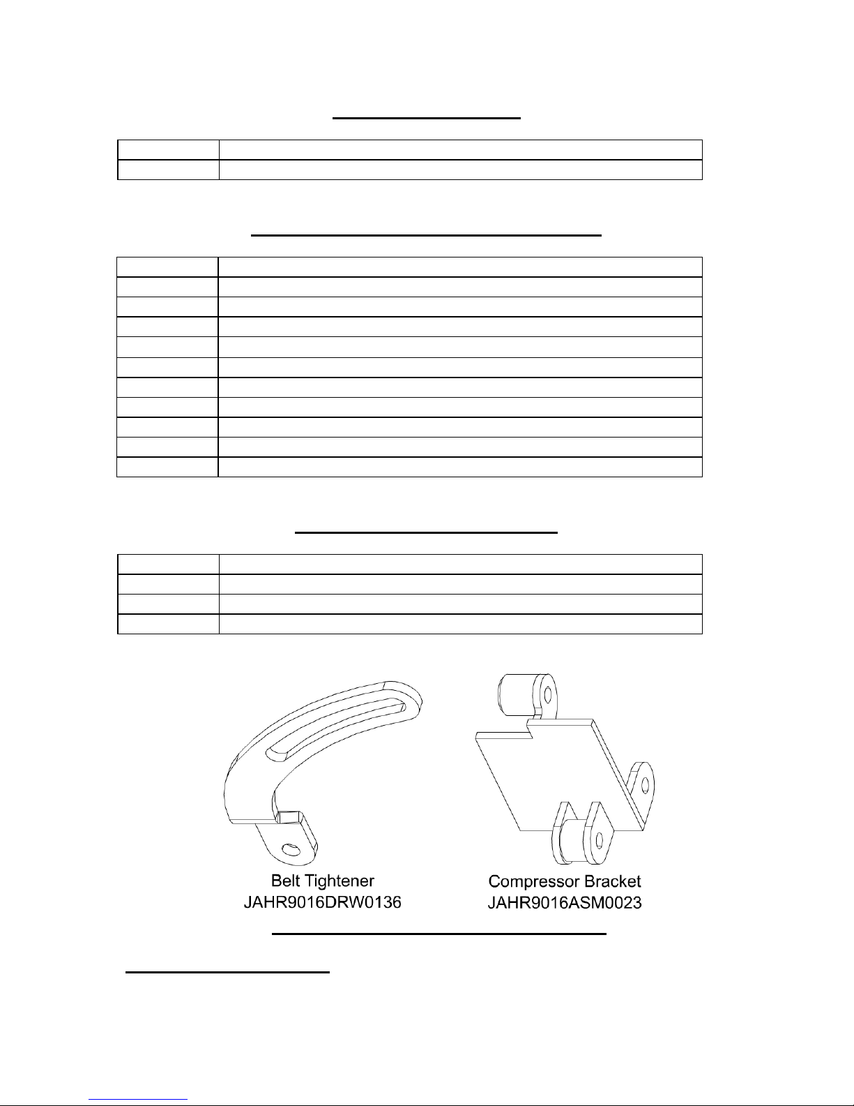
One Compressor Bracket
One Belt Tightener
One M10 X 100 X 1.5mm Carriage Bolt, YD
One M10 X 90 X 1.5mm Flange Bolt, YD
Two M10 X 1.5 Flange Nuts, YD
Two 3/8” X 1 1/2” Flange Bolt, YD
Two 3/8” Flange Nut, YD
One 31/64” X 52 3/8” V-Belt
One 1/2” X 24 1/2” V-Belt
One Compressor
OPTIONAL HEATER PARTS LIST
QUANTITY SIZE and ITEM
Two 3/8 NPT X 5/8” Barb-135° Fitting
Two HS-10 Hose Clamps
30 LF Heater Hose
CAB PREPARATION AND INSTALLATION.
Basic Tractor Preparation
7
Page 8
Park the tractor in a well ventilated location on a flat and level surface. Fully
lower the cutting units to the ground, engage the parking brake, turn the ignition
switch to the off position, and remove the key.
——————————————————————————————————
Wait for all movement to stop before making any adjustments or modifications.
Take this opportunity to thoroughly inspect the equipment and perform other
required maintenance. Drain all but one gallon of fuel from the fuel tank.
Warning - Handle fuel with care – it is highly flammable. Use an approved
container, the spout must fit inside the fuel filler neck. Avoid using cans and
funnels to transfer fuel.
——————————————————————————————————
Tractor Preparation
Note - Retain all fasteners and parts for reassembly.
——————————————————————————————————
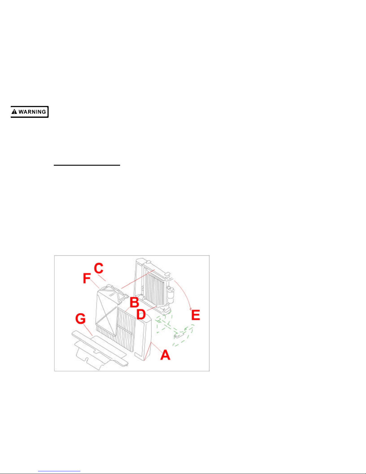
Move oil cooler to service position. Remove end cap (A) from left side of
cooler. Slide screen (B) out from front of oil cooler. Unfasten knobs (C) located
on top of oil cooler, and remove plastic shield (F) from front of oil cooler. Release
prop rod (D) at bottom of cooler and position hydraulic line to the front of it, so
hose can move freely. Swing cooler up and away from radiator as shown (E).
Insert prop rod into hole in frame to hold oil cooler in its service position. Remove
floor shield (G) from tractor.
Figure One
——————————————————————————————————
Remove fuel tank. Remove four 5/16” screws and corresponding hardware (H),
holding left front fender to frame. Remove fender. Disconnect wires from fuel
sender (J), close fuel tank shut-offs, and disconnect fuel lines from bottom of
tank. Remove two 1/2” carriage bolts and corresponding hardware (L) securing
8
Page 9
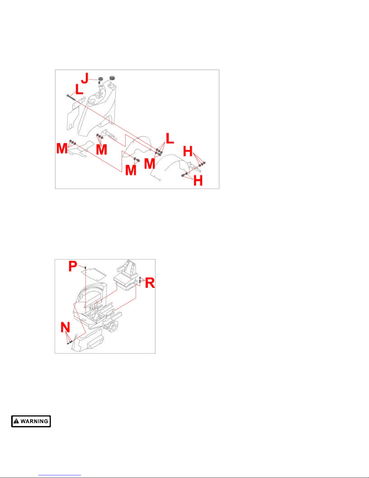
fuel tank to frame. Remove two remaining 5/16” screws (M) holding fender wall to
frame and remove fender wall. Lift fuel tank out and away from tractor. Note - Be
careful not to damage fittings.
Figure Two
——————————————————————————————————
Remove seat. Remove three 5/16” screws, lockwa sher and washers (N) holding
heat shield to hydraulic tank, and remove shield. Remove four 7/16” truss head
screws (P) holding floor board to frame. Remove floorboard. Remove four 3/8”
screws and corresponding hardware (R) holding seat pan to frame. Disconnect
wire harnesses from seat. Remove seat and seat pan assembly from tractor.
Figure Three
——————————————————————————————————
Loosen hydraulic tank. Remove four 5/16” screws and corresponding hardware
(S) securing right fender to frame. Remove fender. Remove front clamp and
loosen rear clamp holding 2” pump suction line in place. Loosen front 5/16”
hardware, and remove rear 5/16” hardware (U) holding fender wall to frame.
Loosen front 1/2” carriage bolt (X), and remove rear 1/2” carriage bolt (V)
securing hydraulic tank to frame. Caution – Hydraulic tank is full of oil. Do not
9
Page 10
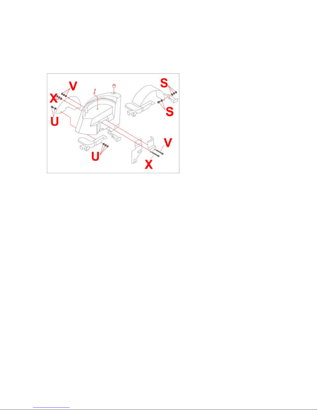
remove all mounting hardware. Tank must remain supported by frame. Carefully
slide rear of hydraulic tank away form center of tractor. Tank should slide a few
inches to provide clearance for rear mounting bracket, but must remain securely
supported by frame.
Figure Four
——————————————————————————————————
Install left rear mounting bracket. Remove four 3/4” bolts (Y), and
corresponding hardware (two on each side) securing frame to frame. Remove
four 3/4” bolts (Z) and corresponding hardware (two on each side) securing rear
tank mounts to cross frame. If the tractor does not have a two-post ROPS
installed, then remove and discard spacer plates (AA). If the tractor does have a
two-post ROPS installed, then remove it using a hoist. Caution – the two -post
ROPS weights approximately 170Lbs. We recommend that you use a hoist when
lifting it off of tractor. Be careful not to damage other tractor parts. Position the
left rear mounting bracket so that it rests on top of the frame (ie. The isolator cup
is directly over the tractor frame.), and install the top 3/4” hardware (Y). Torque
nuts to 200-240 ft-lbs. Insert a rubber isolator in the mounting bracket isolator
cups. Repeat for right rear mounting bracket.
10
Page 11
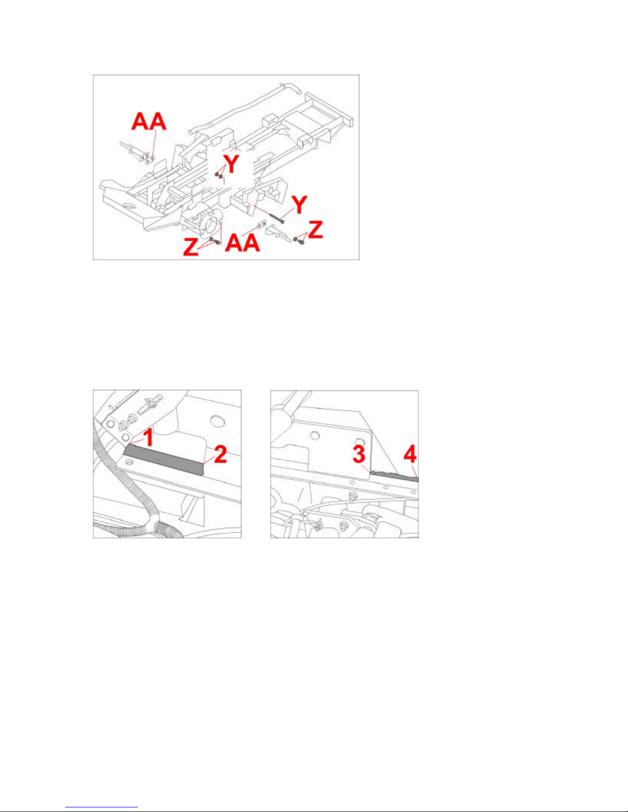
Figure Five
——————————————————————————————————
Install left underseat NDAX. Take the 1” X 1” NDAX (1) remove the backing
and place it on the seat mount. Start at the back and work your way forward until
you reach the left tank mount (2). See Figure 6. Take the 3/4” X 3/4” NDAX,
remove backing and place it along the seat mount, starting where the 1” X 1”
NDAX ended, and working your way up to the platform mount (4). See Figure 7.
Repeat for right side.
Figure Six Figure Seven
——————————————————————————————————
Split the remaining 1” X 1” NDAX into two 8” lengths. Peel the backing off one
piece and stick it to the other (5). Move the new piece into position on the left
side of the machine between the brake cables and the left tank.
11
Page 12
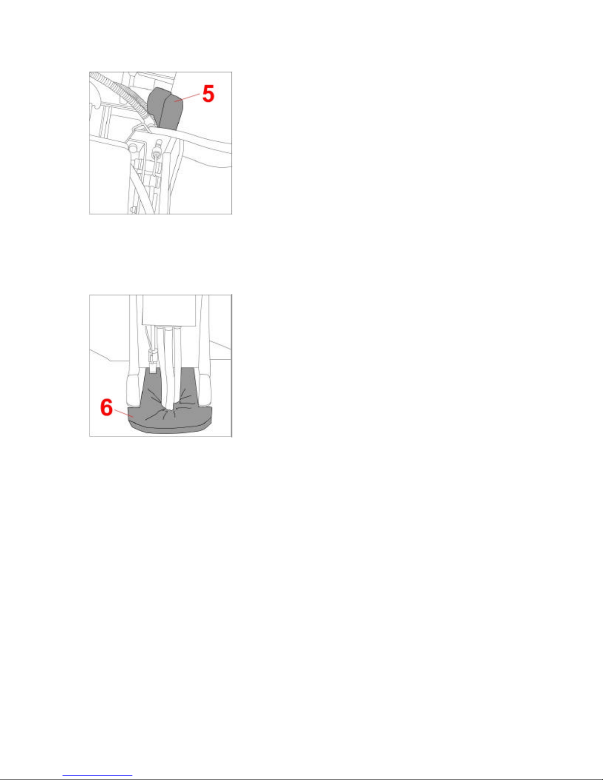
Figure Eight
——————————————————————————————————
Install standard acoustic foam. Remove the front casing of the steering tower.
Move the foam into position inside the tower (6). Once the foam is in place, peel
off the backing and secure it into place with the adhesive side.
Figure Nine
——————————————————————————————————
Install hydraulic tank. Slide hydraulic tank back into position. Tighten front 1/2”
carriage bolt and hardware (X). Install and tighten rear 1/2” hardware (V). Lift rear
tank mount into position and secure to right rear mounting bracket and
crossframe with 3/4” hardware (Z). Torque nuts to 200-240 ft-lbs. Install rear and
tighten front 5/16” fender wall hardware (U). Reinstall fender with four 5/16”
crews and hardware (S). Install clamps securing 2” pump suction line.
12
Page 13
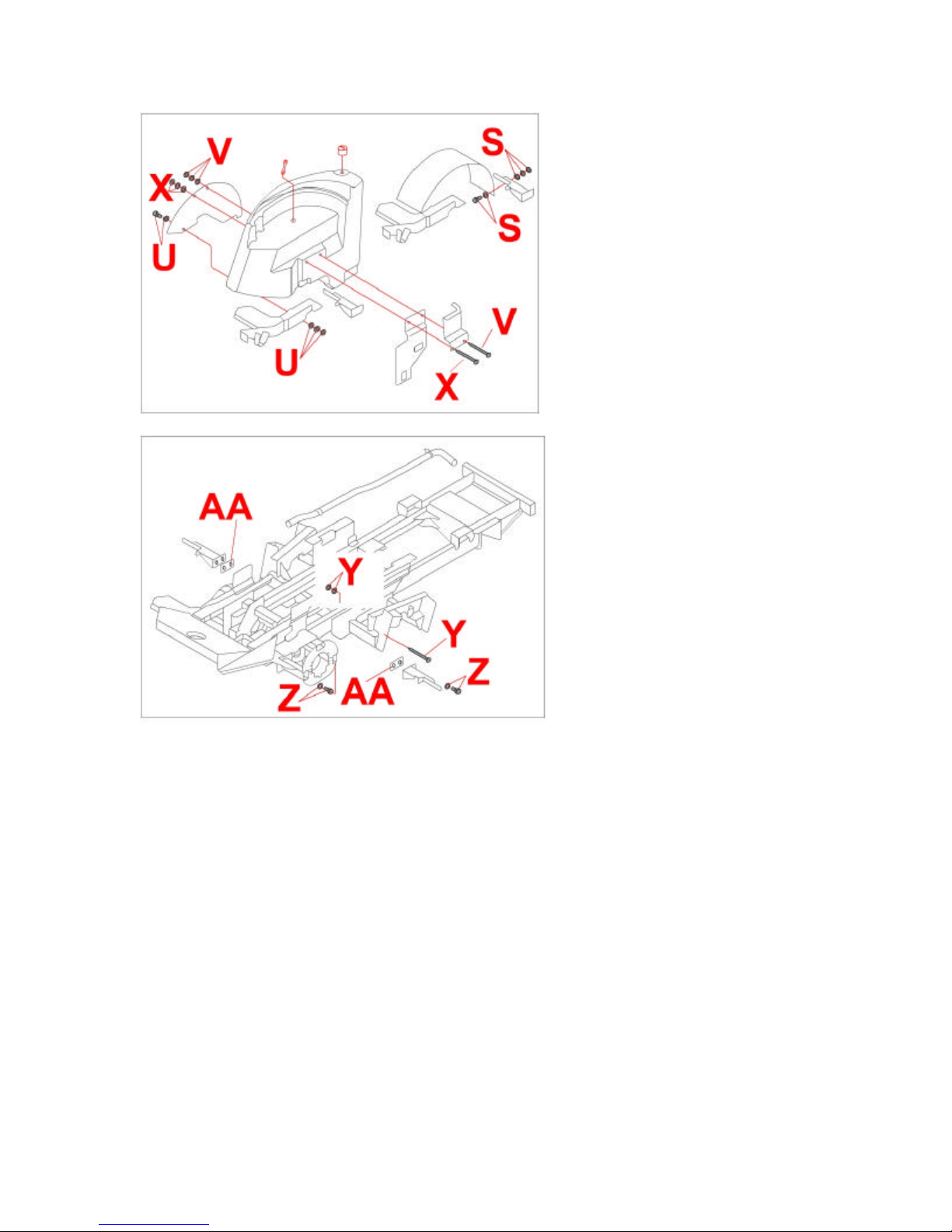
Figure Four
Figure Five
——————————————————————————————————
Install front mounting bracket. Bolt the front mounting bracket (13) over the
front lip of the foot platform using the 3/4” bolts (14) and corresponding hardware.
Find the two 1/2” nuts welded onto the left and right sides of the bracket. Mark
the hole locations on the side lips of the foot platform and remove the front
bracket. Drill two 9/16” holes through the lip of the foot platform at the marked
locations. Loosely bolt the front bracket to the machine using 1/2” X 1 1/2” bolts
(15) and lock washers on the right hand side under the platform. Use 1/2” X 2”
bolts and lockwashers on left hand side under platform. Inse rt a rubber isolator
(16) in the mounting bracket isolator cups.
13
Page 14
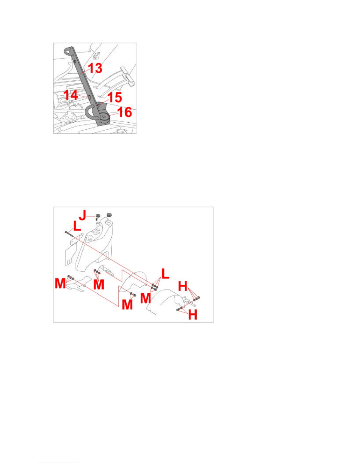
Figure Fourteen
——————————————————————————————————
Install fuel tank. Place fuel tank back on tractor. Install two 1/2” carriage bolts
and hardware (L) from frame to fuel tank and fender wall. Lift rear tank mount
into position and secure to left rear mounting bracket and crossframe with 3/4”
hardware. Torque nuts to 200-240 ft-lbs. Install 5/16” hardware (M) securing
fender wall to tank mount. Reconnect wires to fuel sender (J) and fuel li nes to
tank. Install fender with four 5/16” screws and hardware (H).
Figure Two
——————————————————————————————————
14
Page 15
Basic Cab Preparation
Important – The side panels and roof are not structural – DO NOT handle the
cab in any way using the side panels or roof.
Note - Retain all fasteners and parts for reassembly.
——————————————————————————————————
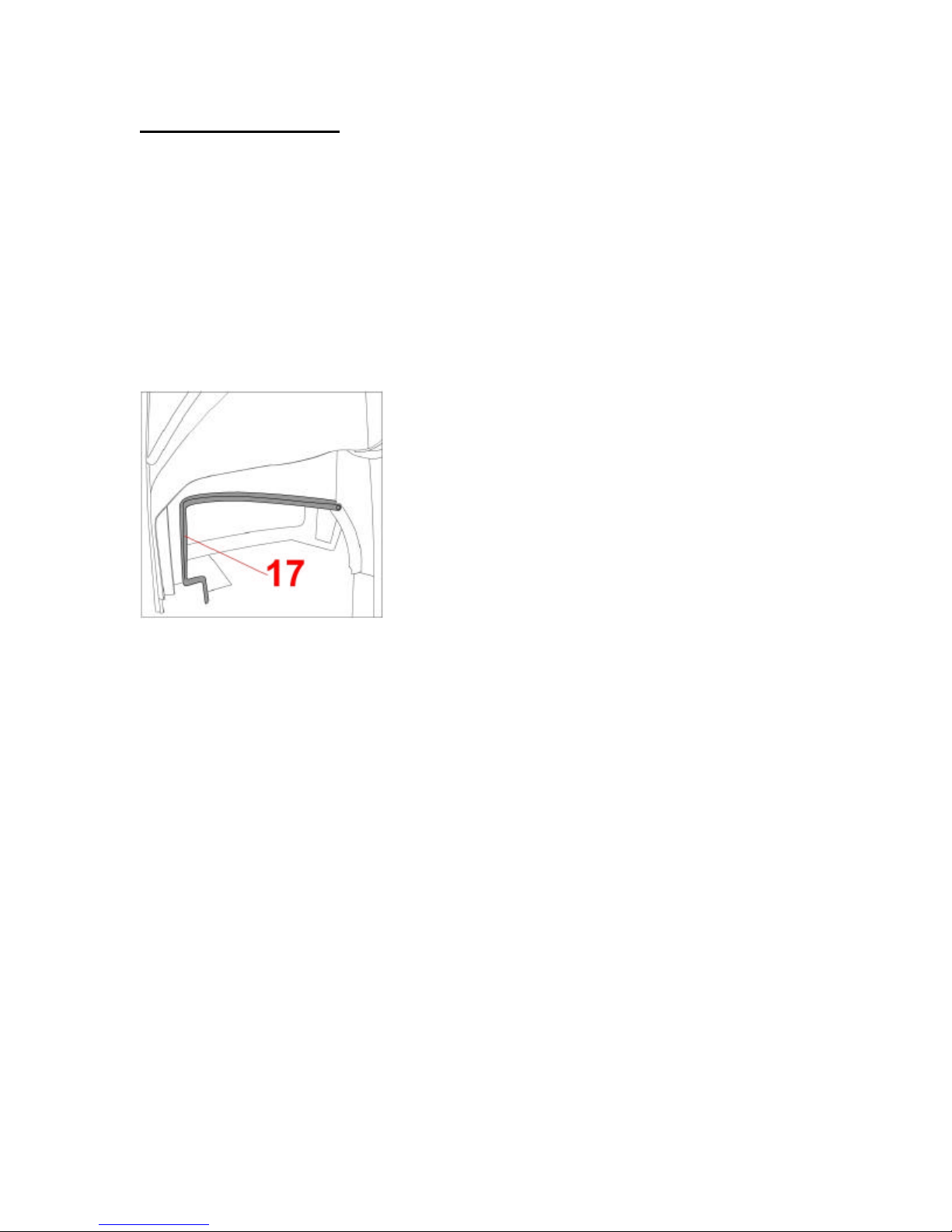
Install cab weather stripping. For the left side panel, install 180° bulb seal (17).
Start at the left front lower corner of the inner steel side panel. Work your way
back until you reach the foam rubber seal at the rear corner of the steel panel.
Repeat for the right side.
Figure Fifteen
——————————————————————————————————
Remove the door and side windows. Release the gas shock from the cab
frame by removing the wire snap ring and pulling the front end of the gas shock
down. Open the door and lift it straight up off the hinge pin. Be careful not to lose
the brass washers. Remove the front right side window by opening window latch
to half -open position, and pulling the latch down so that the stud passes through
the slot in top surface of the latch. Open the window and lift it straight up off of
the pin hinge. Be careful not to lose the brass washers.
——————————————————————————————————
Without optional cab lift bracket only. If you do not have the optional cab
lifting bracket, it will be necessary to remove the side windows as well. Open the
side window and remove Rue Ring Cotter from clevis pin. Slide slider off of clevis
pin. Lift off side window. Be careful not to lose the brass washers.
——————————————————————————————————
With optional cab lift bracket only. Install the cab lifting bar. Pass the cab
lifting bar through the door opening and the escape window opening (18).
Position the lifting bar against the front surfaces of both hinge posts and slide it
upward so that the rubber padded brackets hook around the inside of each hinge
15
Page 16
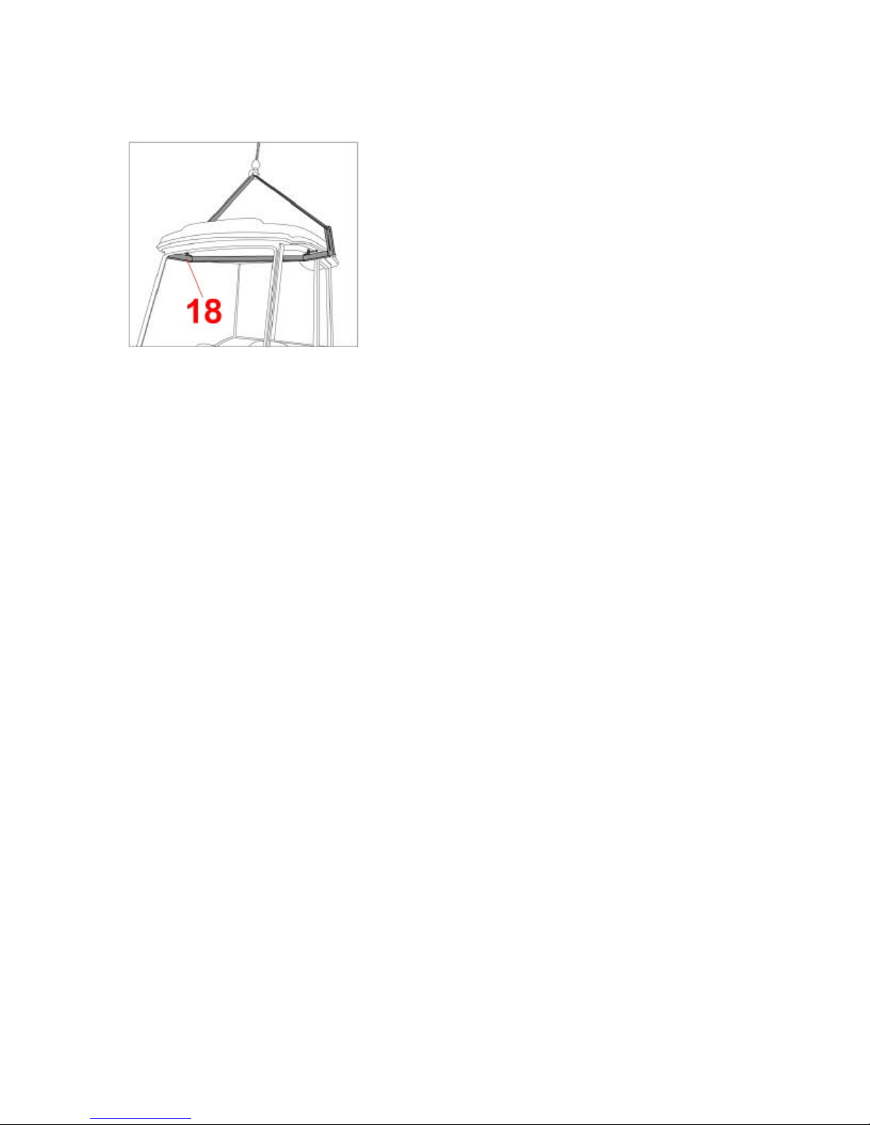
post. Attach lifting bar to hoist, ensuring that lifting bar, chains or cables will not
damage the cab roof. Remove bolts securing cab to pallet. Lift cab with hoist.
Figure Sixteen
——————————————————————————————————
16
Page 17
Beginning Cab Installation
Lowering the cab. Begin lowering the cab carefully onto the tractor, guiding the
rear mounts between the tanks. Ensure that fuel and oil filler spouts clear the cab
side panels. Ensure that the heater hose does not become pinched under cab.
Lower the cab until the cab mounts are resting on the rubber isolators in the front
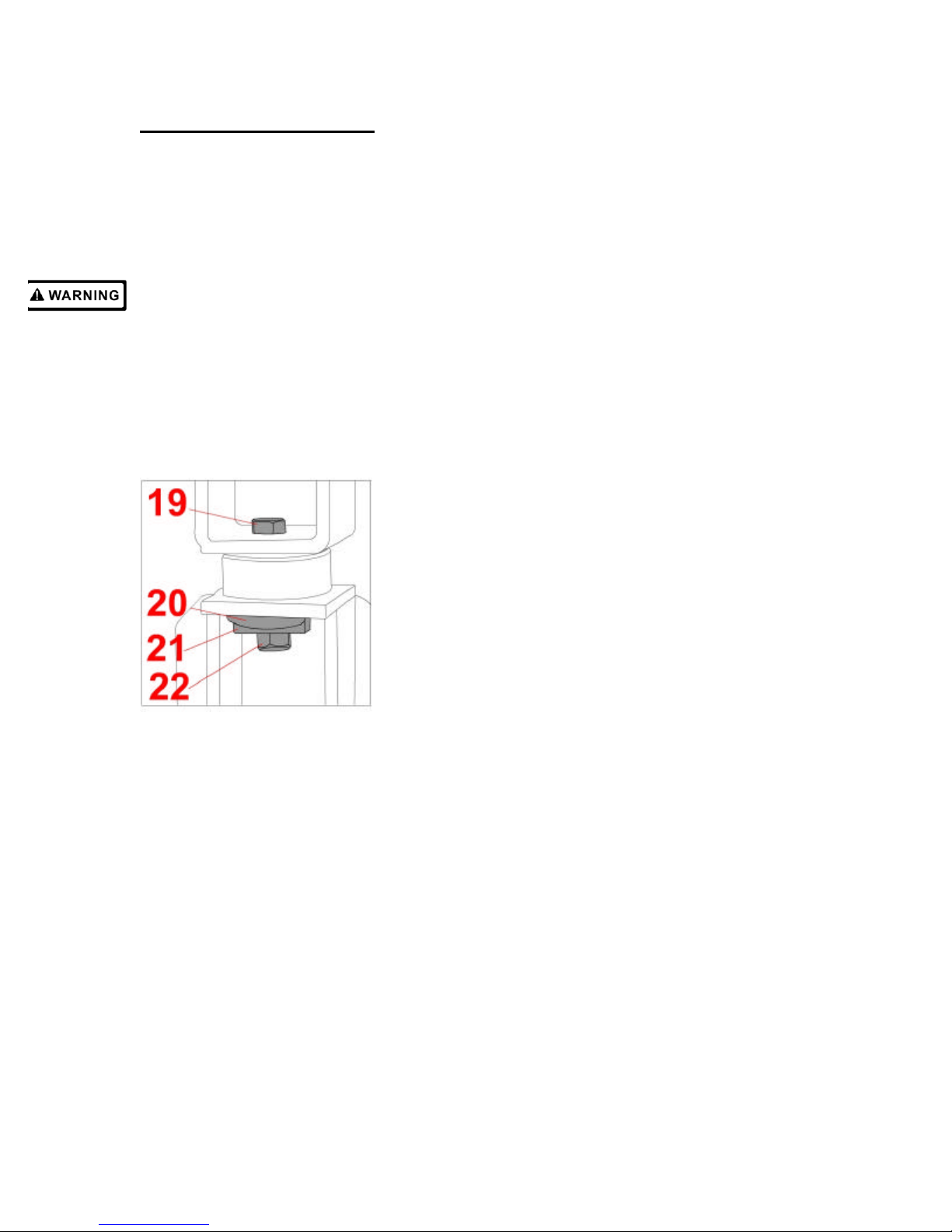
and rear bracket isolator cups. Insert the four 5/8” X 3 1/2” bolts (19) into the
mounts from above. From below, first slip on the rubber washer (20), then the
thick square structural washer (21), and finally the 5/8” nut (22). Warning - The
structural washer is crucial to the structural integrity of the ROPS frame. It must
be installed between the bottom surface of the mounting brackets and the nut. If
it is not installed, the nut could be pulled through the mounting bracket during a
rollover, and protection would be lost. Torque nut to compress isolator until the
distance between top plate of bracket and bottom plate of mount is 1 1/8”. (See
figure 17). Torque 5/8” bolts through front surface of front mounting bracket to
120-180 ft-lbs. Locate front left mounting bolt, and tuck the floormat under cab
frame crossmember, at the bottom of the windshield.
Figure Seventeen
——————————————————————————————————
With optional cab lift bracket only. Remove, but do not discard the cab lifting
bar. It may be required for future cab installations.
——————————————————————————————————
Inspect the gap between the fiberglass side panels and the plastic fuel and
hydraulic oil tanks. Wedge in rubber spacers, if necessary (not supplied), to
ensure that the side panels do not touch the tanks. Vibrations may cause the
panels to wear holes in the tank.
17
Page 18
Installing Cab Options
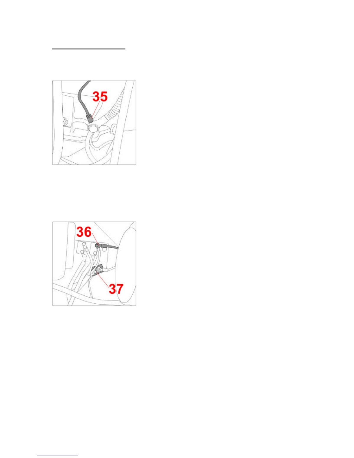
Attach the power wires. Take the cab ground wire (35) and run it to the
machine ground, located on the rear left side of the engine. Ensure that the wire
does not interfere with any moving parts of the engine.
Figure Twenty-one
——————————————————————————————————
Take the loose end of the jumper wire and attach it to the machine power source
(36). Take the cab power wire and the breaker and attach them to the machine
power source below the jumper wire connection (37). Ensure that the power wire
does not interfere with any moving parts of the engine.
Figure Twenty-two
——————————————————————————————————
18
Page 19
Completing Cab Installation
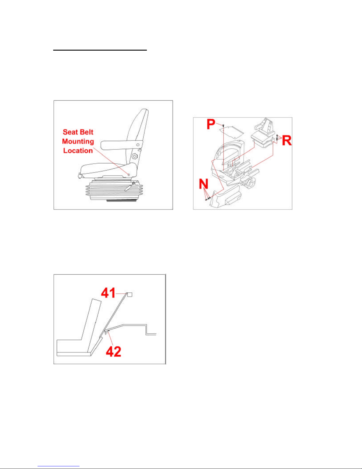
Install seat. Install seat belt assembly on to the seat using the instruction sheet
provided with the belt. (Figure 25) Install seat pan assembly (Figure 3) using four
3/8” screws and corresponding hardware (R). Connect wire harnesses. Install
floorboard using four 7/16” truss head screws (P). Install heat shield to hydraulic
tank with three 5/16” screws, lockwashers, and washers (N).
Figure Twenty-five Figure Three
——————————————————————————————————
Finishing tractor reassembly. Cut out shaded areas of machine floor shield as
shown in Figure Twenty-six to provide clearance for rear mounting brackets.
Secure cab rear panel with two 1/4” X 1/2” flange bolts (41). Replace machine
floor shield. Tuck the front lip of the floor shield into the channel provided in the
rear surface of the cab rear access panel (42).Figure Twenty-six
Figure Twenty-seven
——————————————————————————————————
19
Page 20
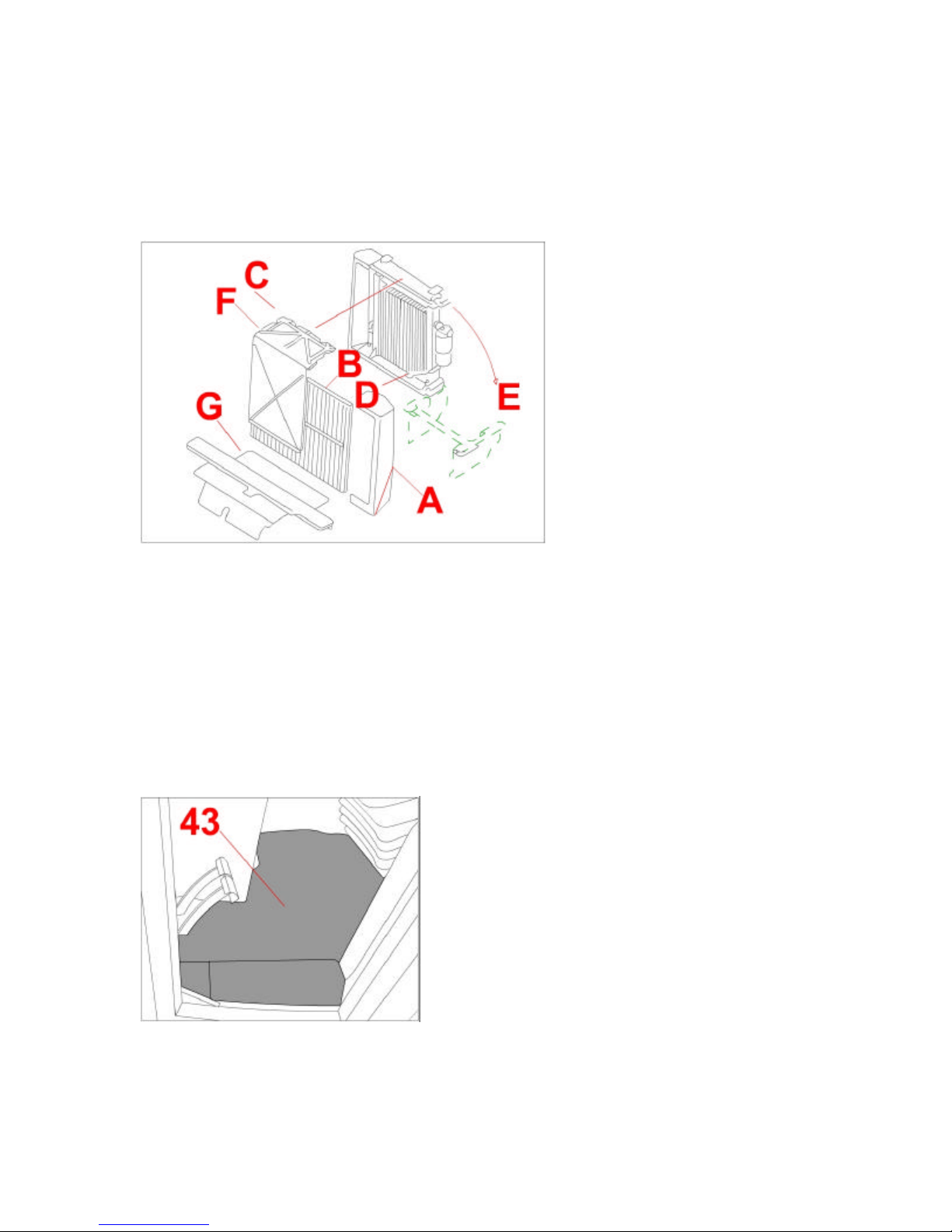
Replace oil cooler, by reversing step four from above. (See Figure 1) Install
floor shield (G) on tractor. Insert prop rod into hole in frame to hold oil cooler in its
regular position (D) at bottom of cooler and position hydraulic line to the front of
it. Swing cooler up and toward radiator as shown (E). Slide screen (B) in front of
oil cooler. Fasten knobs (C) located on top of oil cooler, and insert plastic shield
(F) in front of oil cooler. Attach end cap (A) from left side of cooler.
Figure One
——————————————————————————————————
Finishing cab installation. Fit pre-cut foot platform floor mat (43) onto foot
platform, and seat platform floor mats to seat platform. If necessary, trim floor
mats to provide close fit to tanks, front of seat assembly, steering tower and front
cab frame members. When fit of floor mat is satisfactory, remove floor mat, apply
adhesive to underside of floor mat and reinstall. Use sealer to seal seams in floor
mat and between floor mat and tanks, and wherever edges of floor mat meets
seat platform, tanks or cab frame. (See Figure Twenty-eight). Reinstall door, right
front window and side windows by reversing the steps described in “Removing
door and windows”.
Figure Twenty-eight
——————————————————————————————————
20
Page 21
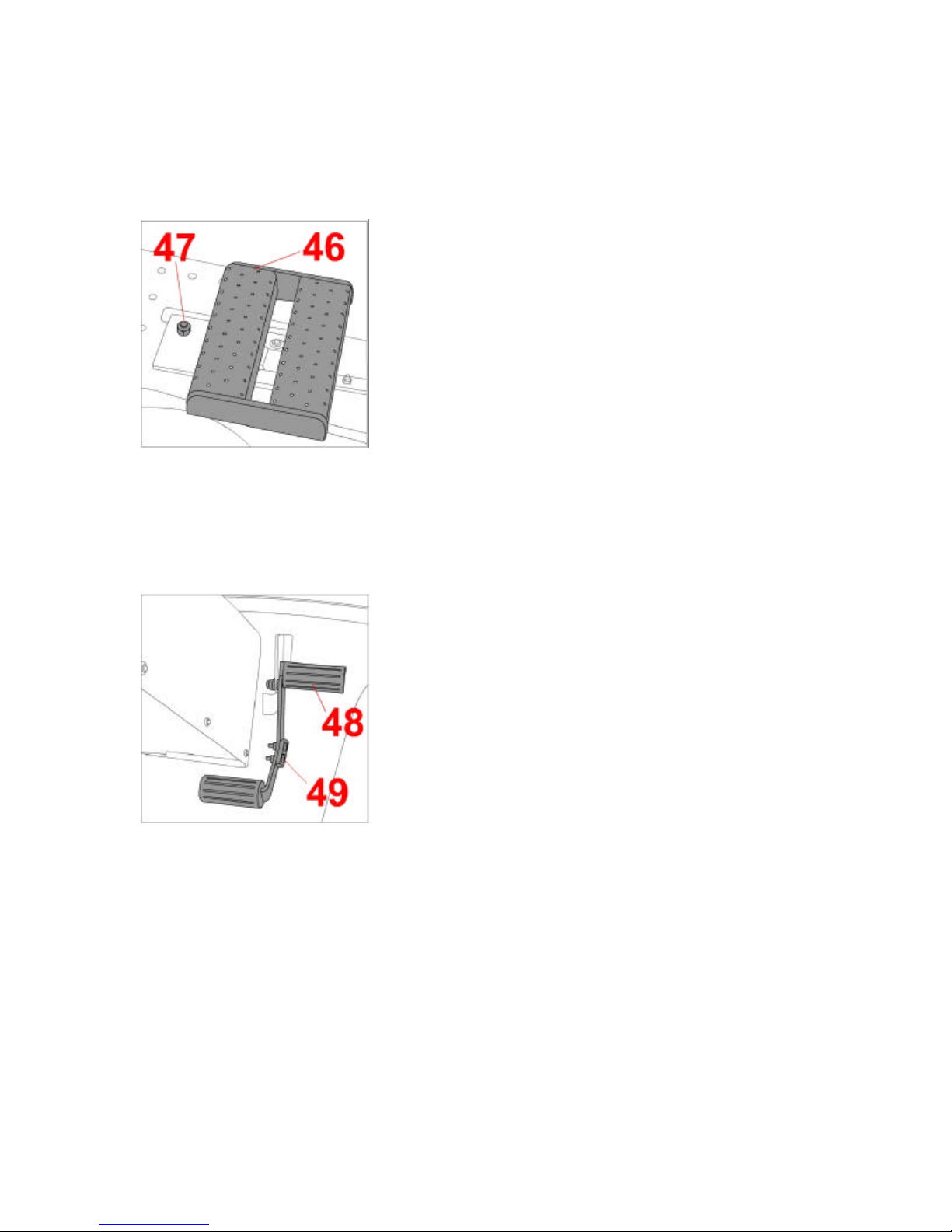
Installing the step. Remove the two bolts on the left wing of the front deck,
where the step fits under a support bracket. Replace those bolts with two 3/8” X 1
1/2” hex bolts (46) supplied. Place step (47) over the bolts, positioning it to the
front and outside of the original step. Secure into place using the nuts removed
from the support bracket.
Figure Thirty-one
——————————————————————————————————
Installing the hydraulic pedal bracket. Remove the fastening hardware from
the factory pedal. Take the pedal off the unit and remove the rubber pads. Take
the rubber pads and attach them to the new hydraulic pedal (48). Attach the new
pedal to the unit using the original hardware (49).
Figure Thirty-two
——————————————————————————————————
Refill fuel tank. Refill fuel tank, being sure to follow all safety precautions listed
earlier. Inspect all hardware regularly, and tighten as required.
——————————————————————————————————
Please Note – In the event of damage or alteration, the ROPS must be replaced
prior to further operation of the machine. All labels, caution decals, and ROPS
serial number plate data must be kept intact and legible.
21
Page 22
Optional Air Conditioner Installation
Disconnecting Battery. Disconnect the battery. Be sure to follow safety
precautions.
——————————————————————————————————
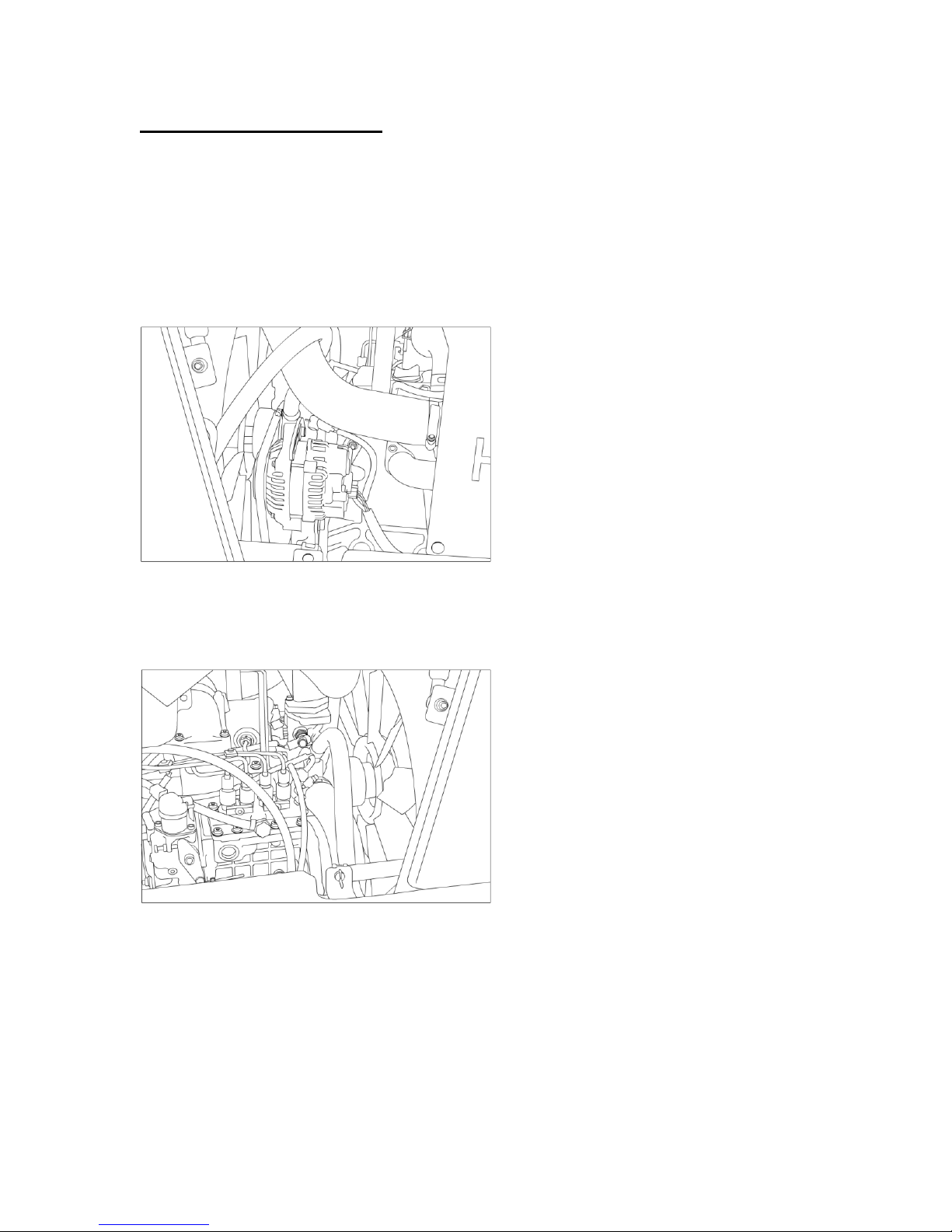
Removing Alternator. Remove the alternator and alternator belt tensioner. Save
hardware for later re-installation.
——————————————————————————————————
Drill out belt tensioner hole to 3/8” wide.
——————————————————————————————————
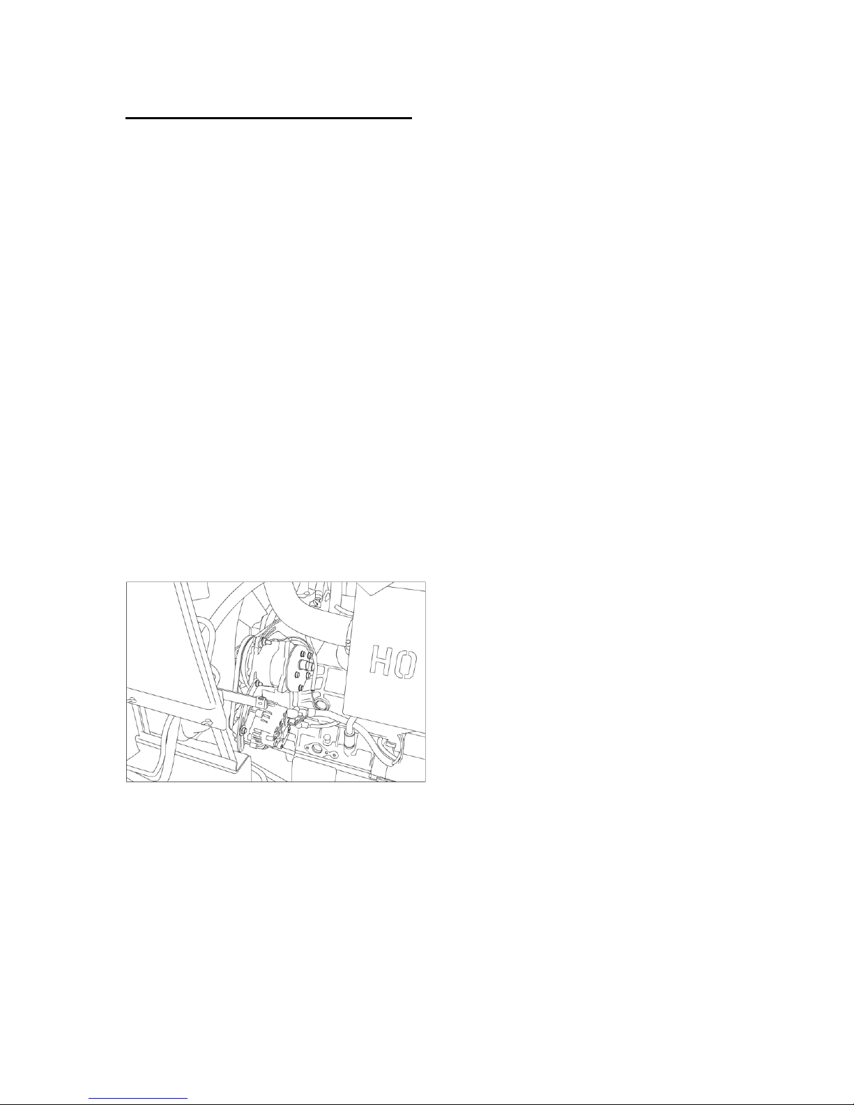
Installing new compressor. Install new compressor on top mounting location,
where the alternator was originally located. Use new provided belt tensioner to
mount to factory location and onto compressor.
——————————————————————————————————
Re-installing alternator. Take alternator and original tensioner and mount to
bottom of bracket. Use bottom compressor mount hole for tension as shown,
using the M10 X 100 X 1.5mm carriage bolt .
——————————————————————————————————
Replacing main V-Belt. Replace main V-Belt with 31/64” X 52 3/8” V-Belt
(12.5mm X 1330mm)
——————————————————————————————————
Installing alternator and compressor V-Belt. Use the 1/2” X 24 1/2” (13mm X
620mm) V-Belt for alternator and compressor pulley.
——————————————————————————————————
22
Page 23
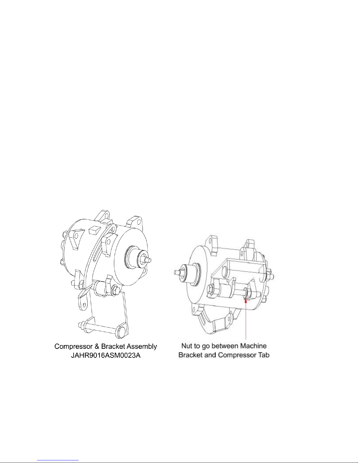
Connecting A/C hoses. Route the A/C hoses, located at back rear of cab, into
engine bay. Connect hoses onto the compressor.
——————————————————————————————————
Connecting A/C wiring. Route the wire labeled A/C to the compressor clutch.
Connect the wires. Re -connect battery ground.
Please Note – ALL A/C charging MUST be performed by a certified A/C
technician, as required by local / provincial / state / federal regulations.
——————————————————————————————————
Filling coolant. Leak check and evacuate the system prior to filling any coolant.
——————————————————————————————————
Charging A/C system. Charge A/C system, according to proper charging
procedures, Fill to 1.75 lbs with R134A refrigerant.
23
Page 24
Optional Heater Installation
Draining anti-freeze. Drain anti-freeze from engine before proceeding.
——————————————————————————————————
Installing the pressure fitting. Locate the thermostat housing on the left side of
the engine. Remove the plug, and install the 3/8” NPT X 5/8” barb - 135° fitting.
This is the pressure fitting.
——————————————————————————————————
Installing the suction fitting. Locate the water pump on right side of engine.
Remove the plug, and screw in 3/8NPT X 5/8” barb - 135° fitting. This is the
suction fitting.
——————————————————————————————————
Connecting heater hoses. Locate the pressure heater hose (labeled) at the
base of left rear cab post. Route the hose into the engine bay. Connect hose to
the pressure fitting using one provided HS -10 hose clamp. Locate hose at the
right rear cab post, and route into engine toward the suction fitting. Connect hose
to suction fitting using one provided HS-10 hose clamp.
——————————————————————————————————
24
Page 25

Testing heater. Refill engine with anti -freeze. Open the cab heater valve using
the rotary control on the switchplate, and turn on the fan. Start the vehicle and
run at PTO RPM for five minutes to build up engine heat. Check for leaks and
add anti -freeze if required. For maximum heater efficiency, all air trapped in the
heater system must be evacuated. TIP: To purge system of air, open radiator
cap while running the engine. Continue running the engine and adding anti-
freeze as required until cab heater produces hot air. PLEASE NOTE: The heater
should produce HOT air at PTO RPM, continue tweaking the heating system until
that point is reached.
——————————————————————————————————
25
Page 26

MINIMUM HARDWARE TIGHTENING TORQUES IN FOOT-POUNDS
Size SAE Grade 8 Gold Plated Hardware and Locknuts
*1/4” *157 (18)
*5/16” *324 (37)
3/8” 48 (65)
7/16” 77 (104)
1/2” 117 (159)
9/16” 169 (2290
5/8” 233 (316)
3/4” 413 (560)
7/8” 667 (904)
Size Grade 8 Metric Hardware and Locknuts
M10 58 (79)
M12 102 (138)
M16 254 (344)
Note: Torque values shown with * are inch-pounds
26
Page 27
Page 28
Page 29
Page 30
Page 31
 Loading...