


WARNING: If incorrectly used this machine can cause severe
injury. Those who use and maintain this machine should be
trained in its proper use, warned of its dangers and should
read the entire manual before attempting to set up, operate,
adjust or service the machine.
Parts and Maintenance Manual
RJ 100 / 032004
24560G-BE (rev.2)
G-Plex III
Series: DP - Engine type: Kubota D722
Product code: USAD001
Series: DN - Engine type: Briggs & Stratton 350447
Product code: USAG001

© 2004, Ransomes Jacobsen Limited. All Rights Reserved

GB-1
JACOBSEN G-PLEX III Series: DN & DP
MAINTENANCE AND PARTS MANUAL
GB
1 CONTENTS
2 INTRODUCTION
2.1 PRODUCT IDENTIFICATION .................................................................................... 2
2.2 SPARES STOCKING GUIDE .................................................................................... 2
2.3 HOW TO USE THE PARTS MANUAL ...................................................................... 3
3 SAFETY INSTRUCTIONS
3.1 OPERATING INSTRUCTIONS .................................................................................. 4
3.2 SAFETY SIGNS ........................................................................................................ 4
3.3 STARTING THE ENGINE .......................................................................................... 4
3.4 DRIVING THE MACHINE .......................................................................................... 4
3.5 TRANSPORTING ..................................................................................................... 4
3.6 LEAVING THE DRIVING POSITION ......................................................................... 5
3.7 SLOPES ................................................................................................................... 5
3.8 BLOCKED CUTTING CYLINDERS ........................................................................... 5
3.9 ADJUSTMENTS, LUBRICATION AND MAINTENANCE............................................ 5
4 SPECIFICATION
4.1 ENGINE SPECIFICATION......................................................................................... 7
4.2 MACHINE SPECIFICATION ...................................................................................... 7
4.3 CUTTING UNIT......................................................................................................... 7
4.4 DIMENSIONS ........................................................................................................... 7
4.5 VIBRATION LEVEL .................................................................................................. 8
4.6 SLOPES ................................................................................................................... 8
4.7 RECOMMENDED LUBRICANTS ............................................................................... 8
4.8 CUTTING PERFORMANCE ...................................................................................... 8
4.9 TORQUES ................................................................................................................ 9
5 LUBRICATION AND MAINTENANCE
5.1 LUBRICATION AND MAINTENANCE CHART.......................................................... 10
5.2 ENGINE ACCESS .................................................................................................... 11
5.3 ENGINE OIL - DIESEL ............................................................................................. 11
5.4 ENGINE OIL FILTER- GASOLINE ........................................................................... 12
5.5 ENGINE OIL - GASOLINE ....................................................................................... 12
5.6 ENGINE OIL FILTER - DIESEL ................................................................................ 13
5.7 ENGINE FUEL FILTER - DIESEL ............................................................................. 13
5.8 AIR FILTER - DIESEL .............................................................................................. 14
5.9 AIR FILTER - GASOLINE ........................................................................................ 15
5.10 ENGINE FUEL FILTER - GASOLINE ....................................................................... 16
5.11 FAN BELT TENSION - DIESEL ................................................................................ 16
5.12 HYDRAULIC FILTER ............................................................................................... 16
5.13 HYDRAULIC OIL ..................................................................................................... 17
5.14 BRAKES .................................................................................................................. 17
5.15 BATTERY ................................................................................................................ 18
5.16 REAR SWING OUT ARM ........................................................................................ 19
6 ADJUSTMENTS
6.1 LEVELING LINKAGE FOR THE FRONT CUTTING HEADS .................................... 20
6.2 MOW/TRANSPORT SPEED CONTROL .................................................................. 21
6.3 SPEED CONTROL PEDAL ...................................................................................... 22
6.4 CUTTING HEAD LIFT AND LOWER TIMING .......................................................... 24
6.4 BLEEDING THE FUEL SYSTEM - DIESEL .............................................................. 24
6.5 BACKLAPPING ....................................................................................................... 25
7 TROUBLESHOOTING
7.1 GENERAL ................................................................................................................ 26
8 SCHEMATICS
8.1 HYDRAULIC CIRCUIT ............................................................................................. 28
8.2 ELECTRICAL CIRCUIT............................................................................................ 30
PARTS LIST
GB-2
GB
JACOBSEN G-PLEX III Series: DN & DP
MAINTENANCE AND PARTS MANUAL
2 INTRODUCTION
2.2 Spares Stocking Guide
To keep your equipment fully operational and productive, Ransomes suggests you maintain a stock of the
more commonly used maintenance items. We have included part numbers for the additional support
materials and training aids.
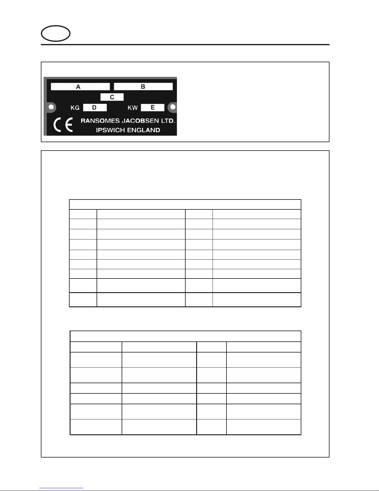
2.1 PRODUCT IDENTIFICATION
A Machine Name
B Serial Number
C Year of Manufacture
D Machine Weight
E Engine Power
straPecivreS
oNtraPnoitpircseD.oNtraPnoitpircseD
415248gulPkrapS061048retliFliOenignE,leseiD
115248retliFliOenignE,enilosaG161048yradnoceS,retliFleuF,leseiD
215248,enilosaGretliFleuFenignE916528yramirP,retliFleuFenignE,leseiD
705248,enilosaGtnemelErenaelCriA2530480tnemelErenaelCriA,leseiD
605248tnemelErenaelC-erPriA,enilosaG261048tleBnaF,leseiD
010298eguaGtuCfothgieH5430072ertil5.0,egnarOnesbocaJ,tniaPpuhcuoT
219828AhctiwSnoitingI1530072
59.0,egnarOnesbocaJ,tniaPpuhcuoT
ertil
8976314retliFciluardyH492418
,kcalB,tniaPpuhcuoT
ertil5.0
lairetaMtroppuSecivreS
oNtraPnoitpircseD.oNtraPnoitpircseD
08930-89879launaMstraPenignEleseiDG26542
srotarepOdnaytefaSenihcaM
E-BGlaunaM
leseiDsrotarepOenignE
launaM
launaMecivreSenignEleseiD
2002/8-C5-3622SMlaunaMstraPenignEenilosaG
20/9-863572
srotarepOenignEenilosaG
launaM
ecivreSenignEenilosaG
launaM

GB-3
JACOBSEN G-PLEX III Series: DN & DP
MAINTENANCE AND PARTS MANUAL
GB
2 INTRODUCTION
2.3 HOW TO USE THE PARTS MANUAL
ITEM NUMBER
Each part which is identified in the illustrations has an item number. Parts which do not have an item number
may not be readily identified in the illustration but are usually closely associated with the immediately adjacent
part.
ASSEMBLIES
A complete assembly, e.g. a wheel motor or hydraulic motor or roll assembly, is listed as a complete item with
subsequent individual components listed separately.
The assembly is listed under it's part number with component parts being listed offset to the right, e.g:-
ITEM PART NO. DESCRIPTION QTY REMARKS
4295 MBG2504 BRACKET 1
4296 MBG3848 LATCH 2
4298 450865 SCREW, M8 x 20, SCKT CSK HD 2
4300 450378 NUT, M8 NYLOC 2
4301 Wl001 Set Of Wheels 1
4301.1 008162130 Wheel & Hub Assy 1 (Rear)
4301.2 008170390 Tyre 1
4301.3 008161830 Rim 1
4301.4 008169140 Hub Assy. 1
4301.5 008169150 Cap 1
4301.6 002993010 Lubricator 1
4301.7 008161990 Wheel & Tyre 2 (Front)
4301.8 008170780 Tyre 2
4301.9 008161250 Rim 2
4302 001341110 Wheel Nut 12
It may not be possible to illustrate every item. With certain items purchased from outside suppliers some
component parts may not be available from Ransomes and may need to be specially ordered from the supplier.
QUANTITIES
Quantities shown are for one assembly or sub-assembly.
USING THE PARTS LIST
Determine the function and application of the part required. Turn to the main index page and select the
appropriate section. Locate the part on the illustration and parts list and read off the quantity from the
appropriate MODEL column.
NUMERICAL INDEX
This is a summary of all part numbers used in the manual arranged in numerical sequence and showing the
page and item number under which the parts appear.
ORDERING OF SPARE PARTS
When ordering replacement parts, it is most important to quote the SERIAL NUMBER of the machine, PART
NUMBER, DESCRIPTION and QUANTITY required.
Any arbitrary modifications carried out on this machine may relieve the manufacturer of liability for any resulting
damage or injury.
ABBREVIATIONS
N/A Not Available
AR As Required

GB-4
GB
JACOBSEN G-PLEX III Series: DN & DP
MAINTENANCE AND PARTS MANUAL
3 SAFETY INSTRUCTIONS
This safety symbol indicates important safety
messages in this manual. When you see this
symbol, be alert to the possibility of injury, carefully
read the message that follows, and inform other
operators.
3.1 OPERATING INSTRUCTIONS
Ensure that the instructions in this book
are read and fully understood.
No person should be allowed to operate
this machine unless they are fully
acquainted with all the controls and the
safety procedures.
Never allow children or people unfamiliar
with these instructions to usethis
machine. Local regulations may restrict
the age of the operator.
3.2 SAFETY SIGNS
It is essential all safety labels are kept
legible, if they are missing or illegible they
must be replaced. If any part of the
machine is replaced and it originally
carried a safety label, a new label must be
affixed to the replacement part. New
safety labels are obtainable from
Ransomes dealers.
3.3 STARTING THE ENGINE
Before starting the engine check that the
brakes are applied, drives are in neutral,
guards are in position and intact, and
bystanders are clear of the machine.
Do not run the engine in a building without
adequate ventilation.
3.4 DRIVING THE MACHINE
Before moving the machine, check to
ensure that all parts are in good working
order, paying particular attention to
brakes, tyres, steering and the security of
cutting blades.
Replace faulty silencers, mow only in
daylight or good artificial light
Always observe the Highway Code both
on and off the roads. Keep alert and
aware at all times. Watch out for traffic
when crossing or near roadways.
Stop the blades rotating before crossing
surfaces other than grass.
Remember that some people are deaf
or blind and that children and animals
can be unpredictable.
Keep travelling speeds low enough for
an emergency stop to be effective and
safe at all times, in any conditions.
Remove or avoid obstructions in the
area to be cut, thus reducing the
possibility of injury to yourself and/or
bystanders.
When reversing, take special care to
ensure that the area behind is clear of
obstructions and/or bystanders. DO
NOT carry passengers.
Keep in mind that the operator or user is
responsible for accidents or hazards
occurring to other people or their
property.
When the machine is to be parked,
stored or left unattended, lower the
cutting means unless the transport
locks are being used.
While mowing, always wear substantial
footwear and long trousers. Do not
operate the equipment when barefoot or
wearing open sandals.
Check the grass catcher frequently for
wear or deterioration. After striking a
foreign object. Inspect. the lawnmower
for damage and make repairs before
restarting and operating the equipment.
If the machine starts to vibrate
abnormally, check immediately.
3.5 TRANSPORTING
Ensure that the cutting units are
securely fastened in the transport
position. Do not transport with cutting
mechanism rotating.
Drive the machine with due
consideration of road and surface
conditions, inclines and local
undulations.
Sudden decelerating or braking can
cause the rear wheels to lift.
Remember that the stability of the rear
of the machine is reduced as the fuel is
used.

GB-5
JACOBSEN G-PLEX III Series: DN & DP
MAINTENANCE AND PARTS MANUAL
GB
3 SAFETY INSTRUCTIONS
3.6 LEAVING THE DRIVING POSITION
Park the machine on level ground.
Before leaving the driving position, stop
the engine and make sure all moving
parts are stationary. Apply brakes and
disengage all drives. Remove the starter
key.
3.7 SLOPES
TAKE EXTRA CARE WHEN WORKING ON
SLOPES
Local undulations and sinkage will change
the general slope. Avoid ground
conditions which can cause the machine
to slide.
Keep machine speeds low on slopes and
during tight turns.
Sudden decelerating or braking can
cause the rear wheels to lift. Remember
there is no such thing as a safe slope.
Travel on grass slopes requires particular
care.
DO NOT USE ON SLOPES GREATER THAN 15°
IMPORTANT: When working on any slope set the
weight transfer, if fitted to its maximum (+) setting.
3.8 BLOCKED CUTTING CYLINDERS
Stop the engine and make sure all moving
parts are stationary.
Apply brakes and disengage all drives.
Release blockages with care. Keep all parts
of the body away from the cutting edge.
Beware of energy in the drive which can
cause rotation when the blockage is
released.
Keep other people away from the cutting
units as rotation of one cylinder can cause
the others to rotate.
3.9 ADJUSTMENTS, LUBRICATION AND
MAINTENANCE
Stop the engine and make sure all moving
parts are stationary.
Apply brakes and disengage all drives.
Read all the appropriate servicing
instructions.
Use only the replacement parts supplied
by the original manufacturer.
When adjusting the cutting cylinders take
care not to get hands and feet trapped
when rotating cylinders.
Make sure that other people are not
touching any cutting units, as rotation of
one cylinder can cause the others to
rotate.
To reduce the fire hazard, keep the engine,
silencer and battery compartments free of
grass, leaves or excessive grease.
Replace worn or damaged parts for safety.
When working underneath lifted parts or
machines, make sure adequate support Is
provided.
Do not dismantle the machine without
releasing or restraining forces which can
cause parts to move suddenly.
Do not alter engine speed above maximum
quoted in Engine Specification. Do not
change the engine governor settings or
overspeed the engine. Operating the
engine at excessive speed may increase
the hazard of personal injury.
When refuelling, STOP THE ENGINE, DO
NOT SMOKE. Add fuel before starting the
engine, never add fuel while the engine is
running.
Use a funnel when pouring fuel from a can
into the tank.
Do not fill the fuel tank beyond the bottom
of the filler neck.
Replace all fuel tank and container caps
securely.
Store fuel in containers specifically
designed for this purpose.
Refuel outdoors only and do not smoke
while refuelling.
If fuel is spilled, do not attempt to start the
engine but move the machine away from
the area of spillage and avoid creating any
source of ignition until fuel vapours have
dissipated.
Allow the engine to cool before storing in
any enclosure.
Never store the equipment with fuel in the
tank inside a building where fumes may
reach an open flame or spark.
If the fuel tank has to be drained, this
should be done outdoors.
Do not spill fuel onto hot components.
When servicing batteries, DO NOT
SMOKE, and keep naked lights away.
Do not place any metal objects across the
terminals.

GB-6
GB
JACOBSEN G-PLEX III Series: DN & DP
MAINTENANCE AND PARTS MANUAL
Hydraulic Fluid escaping under pressure
can penetrate skin and do serious
damage. Immediate medical assistance
must be sought.
WARNING
Batteries produce explosive gases and
contain corrosive acid and supply levels
of electrical current high enough to cause
burns.
WARNING
DO NOT USE ON SLOPES GREATER THAN 15°
WARNING
3 SAFETY INSTRUCTIONS
DANGER - Indicates an imminently hazardous
situation which, if not avoided, WILL result in
death or serious injury.
WARNING - Indicates a potentially hazardous
situation which, if not avoided, COULD result
in death or serious injury.
CAUTION - Indicates a potentially hazardous
situation which, if not avoided, MAY result in
minor or moderate injury and property
damage. It may also be used to alert against
unsafe practices.
IMPORTANT: Transport speed is for highway
use only. Never select transport speed
on grass areas or uneven or unsurfaced
roads or tracks.
The operating Instructions for the Cutting Units are
contained in a separate Publication .
California Proposition 65
Engine Exhaust, some of its constituents,
and certain vehicle components contain
or emit chemicals known to the state of
California to cause cancer and birth
defects or other reproductive harm.
WARNING
Before releasing transport latches it is
important that all cutting units are fully
raised.
1. Park the machine on level ground.
2. With the engine running at operating
speed raise the cutting units to their
maximum position by operating lift
levers whilst seated in the driving
position.
3. Disengage drives, stop the engine and
make sure all moving parts are
stationary. Apply brakes and remove
the starter key.
4. transport latches can now be released.
WARNING
Battery posts, terminals and related
accessories contain lead and lead
compounds.
WASH HANDS AFTER HANDLING
WARNING

GB-7
JACOBSEN G-PLEX III Series: DN & DP
MAINTENANCE AND PARTS MANUAL
GB
4 SPECIFICATIONS
4.1 ENGINE SPECIFICATION
TYPE:TYPE: Kubota 15.5KW @ 3600 RPM,
3 cylinder Dioesel engine, 4
stroke, water cooled, 719cc
with 12V electric start.
Model: D722-E
Maximum Speed: 3400 RPM (No load)
Idle Speed: 1500 RPM
Oil Sump Capacity:3.2 litres
Firing Order: 1, 3, 4, 2.
Fuel: No. 2-D Diesel fuel (ASTM D975)
4.1.1 ENGINE SPECIFICATION
TYPE:TYPE: Briggs & Stratton 13.5KW @
3600 RPM, V twin gasoline
engine, 4 stroke, air cooled,
719cc with 12V electric start.
Model: Vanguard 350447 Type 1294
Maximum Speed: 3400 RPM (No load)
Idle Speed: 1500 RPM
Oil Sump Capacity:1.4 litres
Fuel: Unleaded Gasoline Minimum 85
octane
4.2 MACHINE SPECIFICATION
Frame construction:
Heavy duty fabricated steel
chassis.
Transmission:
Variable displacement
hydrostatic pump with high
speed low torque wheel motors.
Cutting unit drive:
Direct drive hydrostatic and reel
drive pumps, bi-directional
hydraulic gear motor with reel
control valve and backlap control
valve.
Speeds:
Cutting: 6 km/h
Transport: 12 kp/h
Reverse: 3 kp/h
Steering: Rear Wheel Steering. Power
Steering, 2.5 turns lock to lock
330mm dia. Steering Wheel
Ground pressure: 1.0 kg/cm
Brakes, Service: Positive hydostatic braking.
Parking: 152 mm Caliper Disk
Capacities:
Cooling System: 3.8 litres
Fuel Tank: 31 litres
Hydraulic Tank: 18.2 litres
Total System 25.7 litres
Battery: 12 volt, Type 093
Alternator Diesel 40amp
Gasoline 15amp
4.3 CUTTING UNIT
Type: Three 559mm wide steerable
floating head.
Reel: 127mm diameter, 7 / 9 / 11
knife.
Rolls: Smooth rear roll, smooth or
grooved front /rear rolls optional.
Bedknife to reel
adjustment: Opposed set screw.
Height of cut
adjustment: Micro-adjusters on front roll.
height of cut: 2.5mm to 16mm Standard blade
2mm to 16mm Tournament
blade.
4.4 DIMENSIONS
Width of cut: 1.57 metres
Overall width with reels: 1.9 metres
Overall height: 1.3 metres
Overall length with reels: 2.1 metres
Overall length with catchers: 2.5 metres
Overall weight of machine
With Reels
Diesel: 630kg
Gasoline: 574kg
Without Reels
Diesel: 535kg
Gasoline: 478kg
Wheel Track: 1.2 metres
Wheel Base: 1.3 metres
SERUSSERPERYT
tcudorP
leehWtnorF leehWraeR
eziSeryTepyTeryTerusserPeryTeziSeryTepyTeryTerusserPeryT
IIIxelP-G021-00.01x02
rp2htoomSnatiTisp9rab26.0
021-00.01x02
rp2htoomSnatiTisp9rab26.0

GB-8
GB
JACOBSEN G-PLEX III Series: DN & DP
MAINTENANCE AND PARTS MANUAL
emaNenihcaM
##seireS
noitareleccAmrA/dnaH
level
HRroHLxaM
s/msnoitareleccA
2
qeAXqeAYqeAZ
2.344.262.1
eulaVtnanimoD2.3
emaNenihcaM
##seireS
ydoBelohW
noitareleccA
level
noitacoLroolF
s/msnoitareleccA
2
noitacoLtaeS
s/msnoitareleccA
2
xyzxyz
naeM4320.09940.0901.00500.05520.01610.0
4.5 VIBRATION LEVEL
The machine was tested for whole body and hand/
arm vibration levels. The operator was seated in the
normal operating postion with both hands on the
steering mechanism. The engine was running and
the cutting device was rotating with the machine
stationary.
Standard ISO 5349: 1986 Mechanical vibration.
Guidelines for the measurement and the
assessment of human exposure to handtransmitted vibration.
Standard ISO 2631-1: 1985 Evaluation of human
exposure to whole body vibration -- Part 1:
General requirements.
4.8 CUTTING PERFORMANCE
Cutting Frequency
7-knife reel - 7.4mm at 6km/h
9-knife reel - 5.7mm at 6km/h
11-knife reel - 4.7mm at 6km/h
4.6 SLOPES
DO NOT USE ON SLOPES GREATER THAN 15°
The slope 15° was calculated using static stability
measurements according to the requirements of
EN 836.
4.7 RECOMMENDED LUBRICANTS
Engine oil:
Diesel: Should be to MIL-L-2104C
or to A.P.I. Classification CD
Gasoline: A.P.I. Classification SE/SF
Hydraulic Oil: GreensCare 68
Grease: Lithium based.
ERUTAREPMETYTISOCSIVLIO
)F°93(C°4EVOBA03EAS
)F°93(C°4WOLEB03-W01ro03-W5EAS

GB-9
JACOBSEN G-PLEX III Series: DN & DP
MAINTENANCE AND PARTS MANUAL
GB
4 SPECIFICATIONS
4.9 TORQUES
SDAERHTCIRTEMHCTIPESROC
aiD
)mm(
EDARG
6.4
EDARG
8.4
EDARG
8.8
EDARG
9.01
EDARG
9.21
)mN()mN()mN()mN()mN(
656 217112
81151032415
0122039548001
219325401641571
412628561232872
6169921752263434
02881152205607748
226521433860692511
4252343486802214641
72674536962158712412
03646268327142428092
332287901391248031073
6392116051210353242805
SDAERHTCIRTEMHCTIPENIF
aiD
)mm(
EDARG
6.4
EDARG
8.4
EDARG
8.8
EDARG
9.01
EDARG
9.21
)mN()mN()mN()mN()mN(
600000
82161235445
0142133688601
212475311951191
417609971252203
61301731472583264
02902972755387049
2218257305755016621
4245327444972313951
72415686173182914132
03517459809138629123
334696821275261630434
6369114951981348441835
SDAERHTCNU
)ni(aiD
EDARG
A
EDARG
S
EDARG
T
EDARG
V
EDARG
X
)tf.fbl()tf.fbl()tf.fbl()tf.fbl()tf.fbl(
4/14.32.99.96.212.51
61/579.814.028.523.13
8/33.215.331.638.545.55
61/77.915.358.752.377.88
2/11.036.1888211531
61/93.34711721161591
8/58.95261571222962
4/3601882013493774
8/7171464005536967
16525969470592511
8/11363489260174312361
4/111157831794199810032
8/310760281369109427103
2/119884142506230332004
SDAERHTFNU
)ni(aiD
EDARG
A
EDARG
S
EDARG
T
EDARG
V
EDARG
X
)tf.fbl()tf.fbl()tf.fbl()tf.fbl()tf.fbl(
4/18.34.013.113.413.71
61/57.78.025.225.825.43
8/39.317.737.046.155.26
61/79.125.952.464.186.89
2/17.335.197.89521251
61/92.84131141971712
8/54.76381791052303
4/3811913443734925
8/7881905055796548
197275771863015521
8/115049901681140513281
4/113659251056139025352
8/319571602422212828143
2/116993072719299632844

GB-10
GB
JACOBSEN G-PLEX III Series: DN & DP
MAINTENANCE AND PARTS MANUAL
5 LUBRICATION AND MAINTENANCE
5.1 LUBRICATION AND MAINTENANCE CHART
serudecorpecnanetniampohskrowerastnioptellubetihwdnaskcehcrotarepoerastnioptellubkcalB
tsriF
8-5
sruoh
yliaD
yrevE
52
sruoh
05tsriF
sruoh
ylkeeW
ro
yrevE
05
sruoh
yrevE
001
sruoh
yrevE
002
sruoh
yrevE
052
sruoh
yrevE
004
sruoh
yevE
006
rosruoh
dnE
fo
nosaeS
noitceS
ENIGNE
leveLliOkcehC
l
5.5/4.5
enignEleseiDliOegnahC
£
5.5
enignEenilosaGliOegnahC
££
3.5
enignEleseiDtnemelEretliFriAkcehC
l
enilosaGtnemelEretliFriAnaelC&kcehC
enignE
l
tnemelEretliFriAecalpeR
£
9.5/8.5
enignEleseiDretliFliOecalpeR
£
6.5
enignEenilosaGretliFliOecalpeR
£
4.5
leseiD-retlifleufenilnicitsalpecalpeR
£ l
01.5
leseiD-noitanimatnocretawrofretlifleufkcehC
£
7.5
leseiD-tnemelEretlifleufecalpeR
£
7.5
enilosaG-retlifleufecalpeR
£
01.5
enignEenilosaGecnaraelCevlaVtsujdA&kcehC
£
enignEeeS
launaM
sniFgnilooCnaelC
l
ENIHCAM
erusserPeryTkcehC
l
skaeLciluardyHrofkcehC
l
sedalBleeR&efinkdeBkcehC
l
tnemtsujdAefinkdeBotleeRkcehC
l
leveLdiulFciluardyHkcehC
l
neercSrelooCliOkcehC
l
sniFrelooCliOnaelC
l
sirbeDrofyaBenignEkcehC
£
ssenthgiTrofstloB&stuNkcehC
£
ssenthgiTrofsgnittiFciluardyHkcehC
£
noitidnoCyrettaBkcehC
£
noisneTtleBkcehC
£
11.5
retliFciluardyHegnahC
££
21.5
liOciluardyHegnahC
£
31.5
sgniniLekarBkcehC
£
41.5
esaergdesabmuihtiLahtiwgniwollofehtetacirbuL
sgniraeBleeRtinUgnittuC
£
srelloRraeR&tnorFtinUgnittuC
£
toviPdaeHgnittuC
£
tnuoMdaeHgnittuC
£
toviPmrAtfiL
£
toviPlortnoCdeepS/woM
£
toviPladePtfiL/woM
£
stoviPrednilyCgnireetS
£

GB-11
JACOBSEN G-PLEX III Series: DN & DP
MAINTENANCE AND PARTS MANUAL
GB
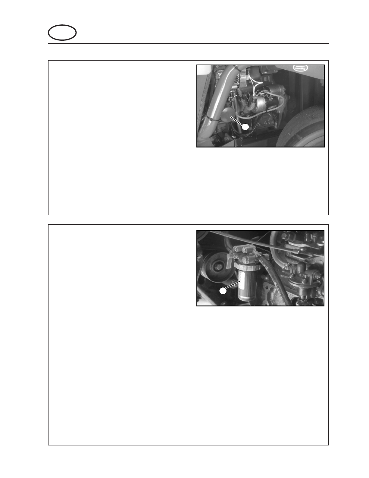
5.3 ENGINE OIL - GASOLINE
Change engine oil.
1 After first warming up the engine remove
the drain plug (Fig. 5.3.2) and drain all the
oil from the crankcase sump.
2 Clean plug and replace.
3 Remove the filler cap (Fig. 5.3.1) and refill
with fresh oil up to the maximum level on
the dipstick (Fig. 5.3.1).
See Specification for oil grade and
amount.
4 Replace filler cap securely.
NOTICE
DO NOT overfill. Engine overheating and
damage may result.
5 LUBRICATION AND MAINTENANCE
5.2 ENGINE ACCESS
The rear section of the unit can be raised for better
access to the engine. Loosen the two handknobs
above the rear fork. Raise the fuel tank frame.
Support it by pivoting the rod beneath the fuel tank
down and securing it in the cup next to the fork pivot
(See Fig. 5.2).
Figure 5.2
Rear Section of Unit Raised
DO NOT remove the fuel tank cap while
the tank is in the raised position.
WARNING
1
Figure 5.3.2
1. Filler Cap
2. Dipstick
Figure 5.3.2
1. Drain Plug

GB-12
GB
JACOBSEN G-PLEX III Series: DN & DP
MAINTENANCE AND PARTS MANUAL
5 LUBRICATION AND MAINTENANCE
5.5 ENGINE OIL - DIESEL
Change engine oil.
1 After first warming up the engine remove
the drain plug and drain all the oil from
the crankcase sump.
2 Clean plug and replace.
3 Remove the filler cap (Fig. 5.5.2) and refill
with fresh oil up to the maximum level on
the dipstick (Fig. 5.5.1).
See Specification for oil grade and
amount.
4 Replace filler cap securely.
NOTICE
DO NOT overfill. Engine overheating and
damage may result.
1
Figure 5.5.1
1. Dipstick
1
Figure 5.5.2
1. Oil Filler Port
5.4 ENGINE OIL FILTER- GASOLINE
Change Engine Oil Filter
1. Drain engine oil and remove oil filter.
2. Before installing new filter, lightly oil filter
gasket with fresh, clean oil.
3. Screw filter on by hand until gasket
contacts filter head. Tighten 1/2 to 3/4
turn more.
4. Add fresh oil. Fill to FULL line on dipstick.
5. Start and run engine at idle and check for
leaks.
6. Stop engine, leave for 15 minutes, recheck oil level. Add oil if required.
Fig. 5.4.1
A. Oil Filter
GB-13
JACOBSEN G-PLEX III Series: DN & DP
MAINTENANCE AND PARTS MANUAL
GB
5 LUBRICATION AND MAINTENANCE
5.6 ENGINE OIL FILTER - DIESEL
Change oil filter cartridge
(a) Remove cartridge from engine by
unscrewing and discard.
(b) Clean area on crankcase.
(c) Apply a thin film of oil to the gasket and
screw in the new cartridge by hand,
securely.
(d) After replacing the new cartridge the
engine oil level will drop, run the engine for
a short period and after ensuring that no
leaks appear, top up with fresh oil to the
level indicated on the dipstick.
NOTICE
DO NOT use a wrench when installing the
filter, use hand pressure ONLY.
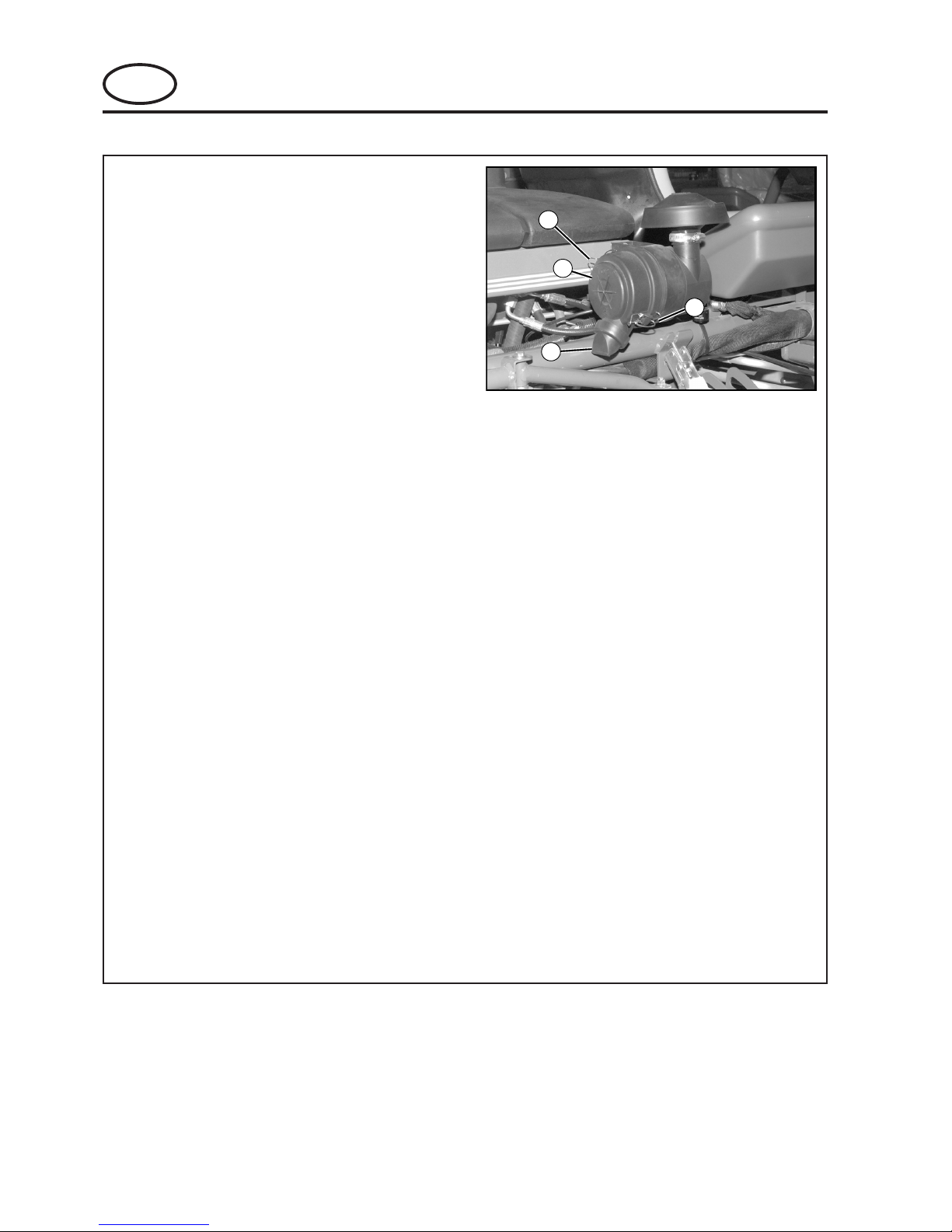
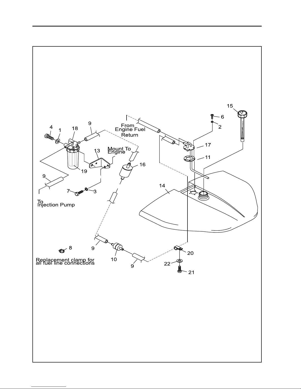
5.7 ENGINE FUEL FILTER - DIESEL
Replace fuel filter element
(a) Unscrew locking ring and remove filter
element (2 Fig. 5.7.1) and discard.
(b) Place new filter element in filter bowl
locating on spring. Position bowl against
gasket in filter head and fit locking ring.
(c) Vent the fuel system.
In-line fuel filter
(a) Release clamp bands either side of in-line
filter and remove fuel pipes.
(b) Fit new in-line filter to fuel pipes, noting
direction of flow and replace clamp
bands.
1
Figure. 5.7.1
1. Fuel Filter Element
1
Figure. 5.6.1
1. Oil Filter Canister
GB-14
GB
JACOBSEN G-PLEX III Series: DN & DP
MAINTENANCE AND PARTS MANUAL
5 LUBRICATION AND MAINTENANCE
5.8 AIR FILTER - DIESEL
Clean Air Filter Element
1. As the element (A) of the air cleaner
employedon this engine is a dry type,
never apply oil to it.
2. Open the evacuator valve once a week
under ordinary conditions-or daily when
used in a dusty place-to get rid of large
particles of dust and dirt.
3. Avoid touching the element except when
cleaning.
4. When dry dust adheres to the element,
blow compressed air from the inside
turning the element. Pressure of
compressed air must be under 7kgf/cm
2
(100psi)
5. When carbon or oil adheres to the
element, soak the element in detergent for
30 minutes then wash it several times in
water, rinse with clean water and dry it
naturally. After the element is fully dried,
inspect inside of the element with a
light and check if it is damaged or not.
(refering to the instructions on the label
attached to the element.)
1
2
3
3
Fig. 5.8.1
1. Cover, 2. Evacuator valve
3. Clips
GB-15
JACOBSEN G-PLEX III Series: DN & DP
MAINTENANCE AND PARTS MANUAL
GB
5 LUBRICATION AND MAINTENANCE
5.9 AIR FILTER - GASOLINE
NOTICE
DO NOT use bent or dented air cleaner housing. DO
NOT use bent or dented air cleaner elements.
IMPORTANT!
WE RECOMMEND THAT THE FILTER ELEMENT
BE REPLACED BEFORE ENGINE PERFORMANCE
IS AFFECTED. THIS MAY OCCUR AT 250 HOURS
OF SERVICE UNDER VERY DUSTY CONDITIONS
OR AT 500 HOURS UNDER NORMAL OPERATING
CONDITIONS. WE DO NOT RECOMMEND
CLEANING THE FILTER ELEMENT BECAUSE OF
THE POSSIBILITY OF DAMAGING IT.
CHECKING THE ELEMENT
To check for damage, pin holes, etc. shine a light
source into the end of the element. If light CANNOT
be seen through the paper, a new element should be
installed. Likewise, if pinholes of bright light appear
in the paper, the element should be replaced (See
Fig. 5.9.1).
Pre-Cleaner
To clean the pre cleaner, seperate it from the
cartridge and wash in liquid detergent and water.
Squeeze dry in a clean cloth.
Fig. 5.9.1
A. Cover, B. Clips, C. Plate, D. Knob
E. Cartidge, F. Foam Pre-Cleaner, G. Body
Removing / Installing Air Cleaner
1. Unhook clips on both sides of cover and
remove cover.
2. Remove knob and plate. Carefully remove
air cleaner assembly to prevent debris
from entering carburettor.
3. Reassemble clean (or new) pre-cleaner on
clean (or new) cartridge.
4. Reinstall air cleaner assembly, plate and
knob.
5. Replace cover and reattach clips to body.
DO NOT use pressurized air or solvents to
clean cartridge. Pressurized air can
damage cartridge; solvents will dissolve
cartridge.
CAUTION
GB-16
GB
JACOBSEN G-PLEX III Series: DN & DP
MAINTENANCE AND PARTS MANUAL
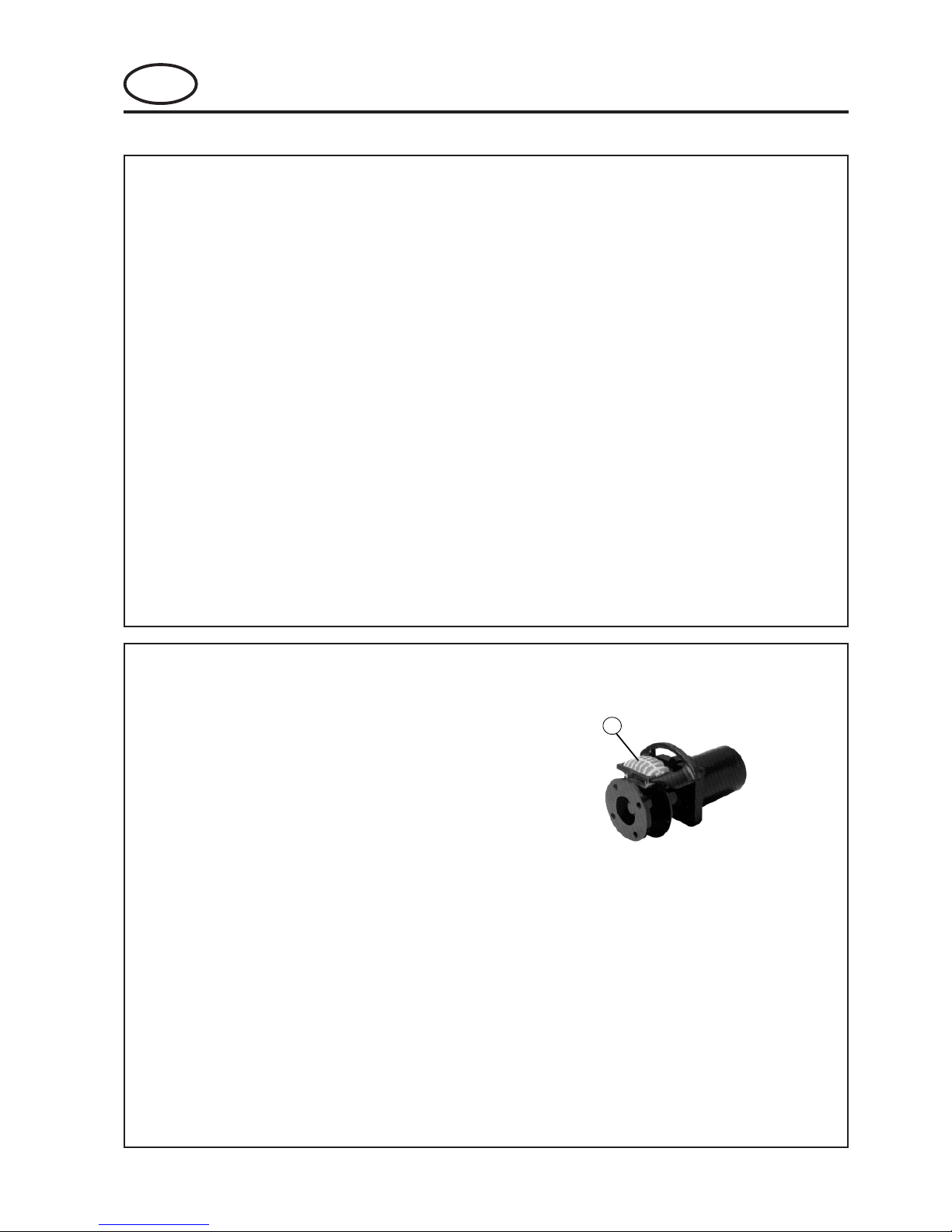
5.11 FAN BELT TENSION - DIESEL
The tension on the belt is correct when the belt can
be depressed 7 to 9mm (0.28 - 0.35in) under a load
of 10kgf (22lbs) midway between the crankshaft
pulley and the alternator pulley.
To adjust:
(a) Release the two bolts (A Fig. 5.11.1)
holding the alternator and adjust alternator
until the tension is correct.
(b) Re-tighten the bolts securely after
adjusting.
5 LUBRICATION AND MAINTENANCE
Figure. 5.11.1
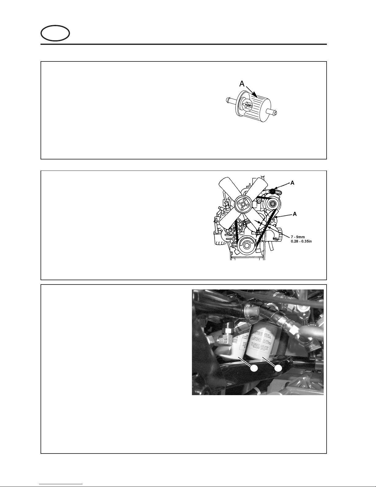
5.10 ENGINE FUEL FILTER - GASOLINE
Replace fuel filte
(a) Release clamp bands either side of in-line
filter and remove fuel pipes.
(b) Fit new in-line filter to fuel pipes and
replace clamp bands.
Fig. 5.10.1
A. Fuel filter
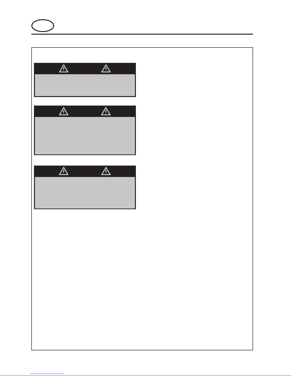
5.12 HYDRAULIC OIL FILTER
The hydraulic oil filter MUST be replaced when:
250 hours of operation occurs.
Yearly.
After a major component failure.
If you notice the presence of water or foam
in the oil.
A rancid odor is detected (indicating
excessive heat).
Always replace the hydraulic filters when changing
oil.
When replacing the hydraulic oil filter, apply a light
film of clean oil to the rubber seal. Screw filter on
until the seal contacts the oil filter base, then tighten
1/2 turn more.
NOTE: DO NOT use wrench when replacing
the filter, use hand pressure ONLY.
11
Figure. 5.12.1
GB-17
JACOBSEN G-PLEX III Series: DN & DP
MAINTENANCE AND PARTS MANUAL
GB
5 LUBRICATION AND MAINTENANCE
5.13 HYDRAULIC OIL
The hydraulic oil MUST be drained and replaced
when:
250 hours of operation occurs.
Yearly.
After a major component failure.
If you notice the presence of water or foam
in the oil.
A rancid odor is detected (indicating
excessive heat).
Always replace the hydraulic filters when changing
oil.
To drain the hydraulic oil, remove the hydraulic oil
filters.
Once the hydraulic oil is replaced, the air must be
purged from the system. Operate the unit for five
minutes to stabilize the oil level.
Once the air is purged and the oil level is stabilized,
fill the tank to its proper level.
The hydraulic fluid reservoir is filled at the factory
with biodegradable hydraulic oil.
5.14 BRAKES
If desired, mineral oil may be used in place of the
biodegradable hydraulic oil.
NOTE: Use of mineral oil will compromise all
biodegradable properties of the biodegradable
hydraulic oil.
When changing to mineral oil, drain the reservoir and
replace the hydraulic oil filters. The system does not
have to be flushed out when changing over. As a
mineral oil alternative to the biodegradable hydraulic
oil, a straight-viscosity ISO 68 type fluid is
recommended for higher temperature environment.
Place the front axle on axle stands and remove the
front wheels. Inspect the Discs and pads for wear
and replace if necessary. Remove all debris from
around the brake assemby and ensure the caliper is
free to float
1
Figure. 5.14.1
1. Caliper
GB-18
GB
JACOBSEN G-PLEX III Series: DN & DP
MAINTENANCE AND PARTS MANUAL
5 LUBRICATION AND MAINTENANCE
Battery posts, terminals and related
accessories contain lead and lead
compounds.
WASH HANDS AFTER HANDLING
WARNING
5.15 BATTERY
UNTRAINED/UNAUTHORIZED persons
should NEVER attempt to service or
recharge the battery in this unit.
WARNING
Battery electrolyte is an acidic solution
and should be handled with care. If
electrolyte is splashed on any part of the
body, immediately flush the exposed
area with liberal amounts of water and
obtain medical aid immediately.
WARNING
NOTICE
Keep top of battery clean and free of
corrosion by washing with a solution of
baking soda and water OR ammonia and
water. Rinse with clean water. Batteries
with heavy corrosion should be removed
and cleaned with solution.
Battery cables should be disconnected
before using a Battery Charger.
GB-19
JACOBSEN G-PLEX III Series: DN & DP
MAINTENANCE AND PARTS MANUAL
GB
6 ADJUSTMENT
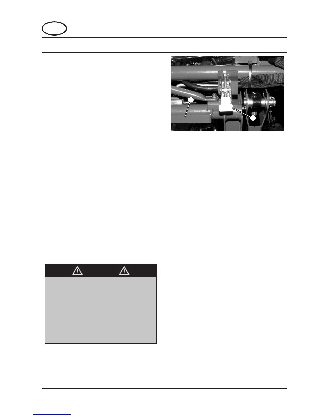
5.16 REAR SWING OUT ARM
NOTE: The rear swing out arm is to allow you
easy access to the rear cutting head. The cutting
heads must be in the raised position. DO NOT
swing the arm out with the cutting heads in the
lowered position.
1. The grass catcher MUST BE removed
before you swing the arm out.
2. Release the draw latch (See Fig. 5.16.1).
3. Pull the handle and swing the rear arm and
cutting head out.
4. After you are properly seated in the
operator's seat, restart the unit and lower
the cutting heads.
5. Shut off the unit and remove the rear
cutting head for service.
6. After you have completed your servicing,
secure the cutting head to the rear arm.
7. After you are properly seated in the
operator's seat, restart the unit and raise
the cutting heads.
8. Shut off the unit and swing the rear arm
back under the unit and secure the arm
with the draw latch (See Fig. 5.16.1).
9. Install the grass catcher.
1
2
Figure 5.16.1
1. Draw Latch
2. Handle
To avoid the possibility of serious injury,
ALWAYS be properly seated in the operator's
seat while the engine is running.
NEVER attempt to drive the machine while
the rear arm is not secured by the draw latch.
Driving the machine with the rear arm out, will
result in damage to the machine and/or cause
serious injury or death of the operator and/or
bystanders.
WARNING
GB-20
GB
JACOBSEN G-PLEX III Series: DN & DP
MAINTENANCE AND PARTS MANUAL
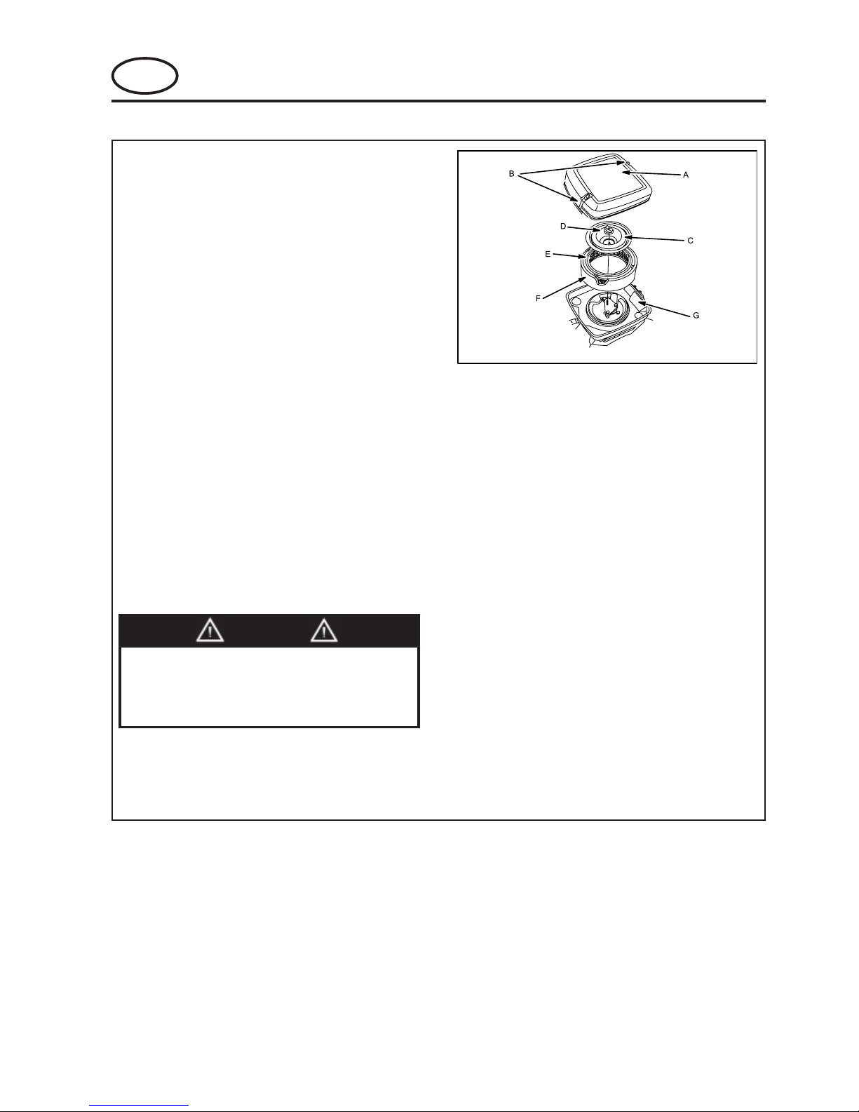
6 ADJUSTMENT
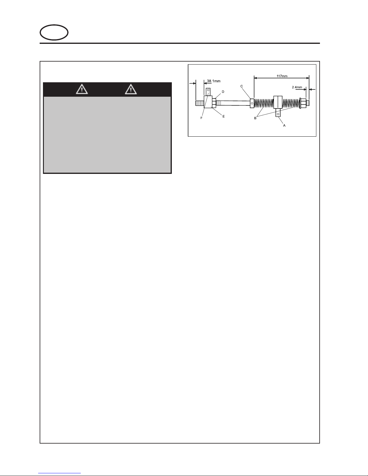
6.1 LEVELING LINKAGE FOR THE FRONT
CUTTING HEADS
Fig. 6.1.1
A. Connector to main frame (DO NOT adjust)
B. Springs
C. Lock collar
D. Jam nut
E. Adjusting connector
F. Adjusting connector secures to lift arm
This procedure must be performed as
specified and only by properly trained
service personnel.
During this entire procedure the reel
enable switch must be in the off position.
Turning on the reel enable switch will
result in damage to the unit and/or
serious personal injury or death to you
the operator or bystanders
WARNING
NOTICE
The dimensions in figure 6.1.1 are factory
preset and the leveling linkage should not
need adjusting. After some time the
linkage may require some adjusting. If it
is required, only make adjustments on the
adjusting connector (E Fig. 6.1.1).
1. With the unit on a level surface
(recommend concrete surface), place
cardboard underneath all three of the
cutting heads.
2. An additional person is needed to stand 3
meters in front of the unit to check on how
level the front heads are when lowering.
Lower the cutting heads and ensure the
entire width of the front heads are parallel
with the level surface as the heads touch
the cardboard.
3. If they do not touch evenly, make an
adjustment using the adjusting connector.
Repeat procedure as needed until the two
front heads touch evenly on the level
surface.
GB-21
JACOBSEN G-PLEX III Series: DN & DP
MAINTENANCE AND PARTS MANUAL
GB
6.2 MOW/TRANSPORT SPEED CONTROL
When cutting heads are raised completely, the
wheel drive speed range is 0 7.5 mph (0 12 Km/
hr). Speed is controlled by use of the direction/
speed control pedal as described in control pedals
section.
When cutting heads are lowered, the forward
movement of the direction/speed control pedal is
restricted by the automatic mow speed control
linkage (the bellcrank stop screw contacts the foot
pedal tab which rotates the pedal upward. This in
turn reduces the ground speed of the unit for
mowing). The mow speed range is 0 3.8 mph (0
6.1 Km/hr).
ADJUSTING MOW SPEED
To determine mow speed, run a time check on how
fast the unit travels in a distance of 50 (15.24 M).
Prepare a level surface with enough room to start
and end beyond the 50 marks.
Place a stake in the ground where you want to begin
timing the unit. Measure and place another stake at
a distance of 50 (15.24 M). Lower the cutting heads
and press the direction pedal forward so the unit is
traveling at full throttle (the cutting heads should be
in the neutral position when timing the unit).
Begin timing the unit when the center of the front tire
aligns with the first stake. Stop timing when the
center of the front tire aligns with the stake placed at
50 (15.24 M). Estimated time for 3.8 mph (6.1 Km/
hr) will be approximately 8.8 to 9.2 seconds. If there
is a significant difference in the times listed above,
you can adjust the mow speed as follows.
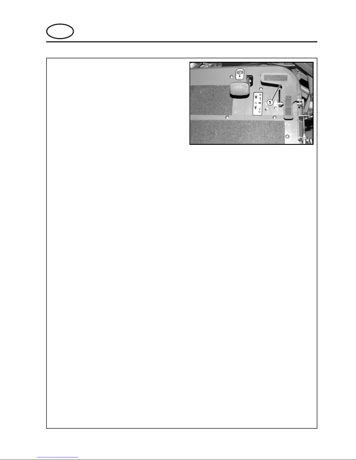
Figure 6.2.1
1. Direction/Speed Pedal
6 ADJUSTMENT
GB-22
GB
JACOBSEN G-PLEX III Series: DN & DP
MAINTENANCE AND PARTS MANUAL
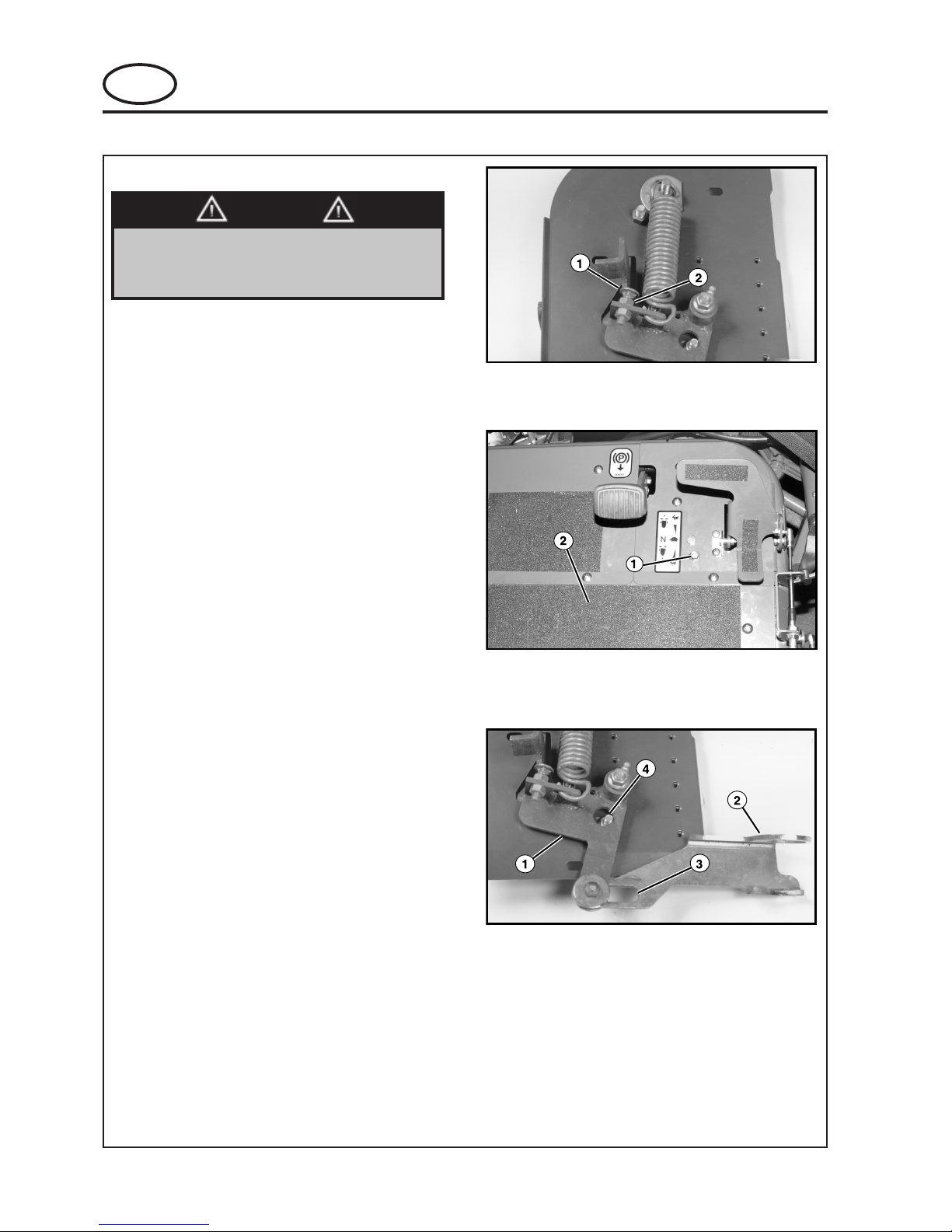
6.3 SPEED CONTROL PEDAL
Figure 6.3.1
1. Mow Speed Adjustment Screw
2. Locking Nut
Figure 6.3.2
1. Bellcrank Stop Screw
2. Center Foot Panel
Figure 6.3.3
1. Bellcrank
2. Lockout Link Angle
3. Lockout Link slot
4. Bellcrank Stop Screw
This procedure MUST be performed as
specified and only by properly trained
service personnel.
WARNING
Adjusting the speed control screw out (increasing
length) will reduce the mow speed. Adjusting the
speed control screw in (shortening length) will
increase mow speed.
Determine which direction to adjust the mow speed
screw. Loosen the locking nut and adjust speed
control screw, snug up the locking nut and run the
time test again, repeat as necessary. When correct
mow speed has been obtained, tighten the locking
nut (See Fig. 6.3.1).
TO SET BELLCRANK STOP SCREW:
NOTICE
The bellcrank stop screw has been set at the factory
and should NOT require adjustment. If stop screw is
loosened or removed, it MUST be properly installed
and adjusted prior to unit operation.
Remove the screws securing the center foot panel
and remove panel (this will allow access to the
lockout link angle).
Loosen the nut on the bellcrank stop screw just
enough to allow the screw to be slid to the left of the
slot (See Fig. 6.3.3).
6 ADJUSTMENT

GB-23
JACOBSEN G-PLEX III Series: DN & DP
MAINTENANCE AND PARTS MANUAL
GB
Figure 6.3.4
Position Bushing to Left of Slot
Rotate bellcrank clockwise (as viewed from above)
and hold the bushing on the lockout link angle to the
left end of the lockout link slot (See Fig. 6.3.4).
Slide the bellcrank stop screw to the left of the slot
located in the foot panel (See Fig. 6.3.2) making
sure the bellcrank contacts the stop screw.
With the screw held tightly against the bellcrank,
tighten the stop screw nut.
Install the center foot panel.
6 ADJUSTMENT

GB-24
GB
JACOBSEN G-PLEX III Series: DN & DP
MAINTENANCE AND PARTS MANUAL
6.4 BLEEDING THE FUEL SYSTEM - DIESEL
This procedure MUST be performed as
specified and only by properly trained
service personnel.
WARNING
The fuel system must be bled when:
Starting the engine for the first time.
The fuel tank becomes completely empty.
The engine has not been used for an
extended period of time.
The fuel filter and/or fuel lines have been
loosened, removed or replaced.
1. Fill the fuel tank.
2. Open the air vent on top of the fuel filter
(See Fig. 6.5.1).
3. Without preheating the glow plugs, turn
the ignition switch to START to operate
the fuel pump. Allow the starter to run the
pump until a steady stream of fuel is
coming out of the fuel filter air vent. Stop
the starter and close the air vent.
4. Open the air vent on top of the injection
pump, open air vent only when engine is
NOT running (See Fig. 6.5.2).
5. Without preheating the glow plugs, turn
the ignition switch to START to operate
the fuel pump. Allow the starter to run the
pump until a steady stream of fuel is
coming out of the injection pump air vent.
Stop the starter and close the air vent.
Catch fuel and dispose of
properly.
To avoid a fire hazard, clean up
any spilled fuel.
WARNING
Figure 6.5.1
1. Fuel Filter Air Vent
2. Secondary fuel filter
Figure 6.5.2
1. Injection Pump Air Vent
6 ADJUSTMENT

GB-25
JACOBSEN G-PLEX III Series: DN & DP
MAINTENANCE AND PARTS MANUAL
GB
6.5 BACKLAPPING
Backlapping on a regular basis will help keep the
cutting edges sharp and extend the life of the reel.
Backlapping may be performed on one cutting head
only, two heads, or all three heads simultaneously. If
backlapping one or two cutting heads is desired,
back off slightly on the bedknifetoreel clearance on
the head(s) not requiring backlapping. This will
eliminate contact between bedknife and reel,
avoiding the possibility of damaging the reel or
bedknife during the backlap process. Always make
bedknife adjustments with the Engine Off.
NOTICE
Make sure the bedknife adjustment is
correct before backlapping. Refer to
Bedknife Adjustment .
2. Slowly turn the restriction valve knob
clockwise until the desired reel rotation
speed is attained. It should be slow
enough so that the reel will not throw off
the backlapping compound as it spins.
3. Apply an even coat of backlapping
compound to the entire length of each
blade of the reel. Use a brush with a long
enough handle to keep you away from the
rotating blades. For best results, use a
handle length which will permit application
of compound while standing in front of the
unit.
4. Once all the blades on the reel are
uniformly sharp, shut off the engine and
switch the reel enable switch to the off
position. Set the reel valve control to the
mow position and close the restriction
valve (all the way clockwise).
NOTICE
To ensure proper reel rotation, make sure
the restriction valve is completely closed.
5. Wash all of the backlapping compound
from all of the heads. Once they are
thoroughly cleaned and dry, apply a light
film of oil to the cutting edges to help
prevent rust.
6. After backlapping, the bedknife adjustment
should be made again.
1
3
2
A
B
N
Figure 6.6.1
2. Backlap Valve
3. Reel Control Lever
A. Mow Position
B. Backlap Position
N. Neutral Position
ALWAYS open the restriction
valve before setting the reel
control lever to BACKLAP
position. DO NOT set the reel
control lever to the BACKLAP
position before opening the
needle valve in the bypass
circuit. This will cause the reels
to start turning IMMEDIATELY at
full speed.
Keep hands, feet and clothing
away from all three reels
whenever the reel control lever
is placed in the backlap position.
When backlap restriction valve is
closed or being closed, all three
reels will rotate in the backlap
direction.
WARNING
1. Open the restriction valve on the reel valve
by turning the knob counterclockwise as
far as it will go (See Fig. 6.6.1).
2. Set the reel control lever to the right for the
backlap position (See Fig. 6.6.1).
1. Start the engine and set the throttle to low
idle. Switch the reel enable switch to the
on position. Lower heads by operating the
paddle or the footswitch.
6 ADJUSTMENT

GB-26
GB
JACOBSEN G-PLEX III Series: DN & DP
MAINTENANCE AND PARTS MANUAL
7.1 GENERAL
The troubleshootijng chart below lists basic problems that may occur during start-up and operation. For more
detailed information regarding the hydraulic and electrical systems contact your area Jacobsen Distributor.
7 TROUBLESHOOTING
smotpmySsesuaCelbissoPnoitcAnoitceS
.tratstonlliwenignE
.tuodemittonsahgulPwolG.1
otgulpwolgwolladnahctiwsnoitingiteseR.1
.enignegniknarcerofebtuoemit
roegrahcnowolyrettaB.2
.evitcefed
yrettabdnayrettabfonoitidnoctcepsnI.2
.snoitcennoc
leufroytpmeknatleuF.3
.detanimatnoc
niarD,retlifegnahC.leufhserfhtiwknatlliF.3
.senilmorfriadeelB,lwobthgismorfretawyna
7.5
.esuFnwolB.4.esuFecalpeR.4
.yaleRretratSevitcefeD.5.yraseccenfiyalerecalperdnatseT.5
deilppatonekarbgnikraP.6ekarbgnikrapylppA.6
otteshctiwsegagnewoM.7
.tuc
.hctiwswomdetnuomhsadegagnesiD.7
tratsotdrahenignE
.ylroopsnurro
leufroytpmeknatleuF.1
.detanimatnoc
niarD,retlifegnahC.leufhserfhtiwknatlliF.1
.senilmorfriadeelB,lwobthgismorfretawyna
7.5
.ytridrodekcolbrenaelCriA.2
saecalperdnarotacidnirenaelcriakcehC.2
.yraseccen
.pmupleuf,srotcejnI.3.launamenignetlusnoC.3
melborPenignErehtO.4.ediuggnitoohselbuortenignetlusnoC.4
.spotSenignE
ytpmeknatleuF.1senildeelbdnaleufhserfhtiwlliF.15.6
erofebtestonskcolretnI.2
taessrotarepognivael
gnivaelerofebnoitisopffoothctiwswomteS.2
.taes
.gnitaehrevOenignE
wolleveltnalooC.1
finoitulosezeerfitna05/05ddadnatcepsnI.1
.deriuqer
detcirtserekatniriarotaidaR.2.rotaidartadraughsemeriwnaelC.2
rotlebrotanretla/pmupretaW.3
.nekorbroesooltlebnaf
.tlebnafdnatlebrotanretla/pmupretawtcepsnI.3
.yraseccenfinethgiT
11.5
gnidlohtonyrettaB
thgilyrettaB.egrahc
.no
yrettabdedorrocroesooL.1
.slanimret
sanethgitdnanaelc,slanimrettcepsnI.1
.deriuqer
nileveletylortcelewoL.2
.yrettab
retawdelletsidhtiwyrettabllifeR.251.5
roesooltlebrotanretlA.3
.nekorb
finethgiT.lebrotanretla/pmupretawtcepsnI.3
.yraseccen
11.5
.evitcefedrotanretlA.4.aunamenigneeeS.4
tucsrednilyC
.ylnevenu
tonedalbmottobotrednilyC.1
.ylreporpdetsujda
.tnemtsujdaedalbmottobotrednilyctcepsnI.1
.wolootdeepsenignE.2 .elttorhtlluftaenignenur,deepsenignekcehC.2
detsujdatondeepsrednilyC.3
.snoitidnocfrutrof
.tuctsebrofdeepsrednilyctsujdA.3
tesrevelnoitceridrednilyC.4
.esreverni
.noitatordrawrofotrevelnoitceridrednilycteS.4
yltcerrocnithgiewdnuorG.5
detsujda
tcerrocllitevlavlortnocthgiewdnuorgtsujdA.5
.deveihcasidnuorg

GB-27
JACOBSEN G-PLEX III Series: DN & DP
MAINTENANCE AND PARTS MANUAL
GB

GB-28
GB
JACOBSEN G-PLEX III Series: DN & DP
MAINTENANCE AND PARTS MANUAL
8.1 HYDRAULIC CIRCUIT
8 SCHEMATICS

GB-29
JACOBSEN G-PLEX III Series: DN & DP
MAINTENANCE AND PARTS MANUAL
GB
8 SCHEMATICS
8.1 HYDRAULIC CIRCUIT
1. Inlet Filter
2. Hydrostat Pump
3. Right Hand Wheel Motor
4. Left Hand Wheel Motor
5 Three Wheel Drive Accessory
6. Power Steering Valve
7. Steering Cylinder
8. Inlet Filter
9 Reel Pump
10. Reel Drive Valve
11. Backlap Valve Accessory
12. Rear Reel Motor
13. Left Reel Motor
14. Right Wheel Motor
15. Ball Valve Accessory
16. Lift Valve
17. Divider / Combiner Valve
18. Left Lift Cylinder
19. Right Lift Cylinder
20. Sequence Valve
21. Rear Lift Cylinder
22. Oil Cooler
23. Reservoir
GB-30
GB
JACOBSEN G-PLEX III Series: DN & DP
MAINTENANCE AND PARTS MANUAL
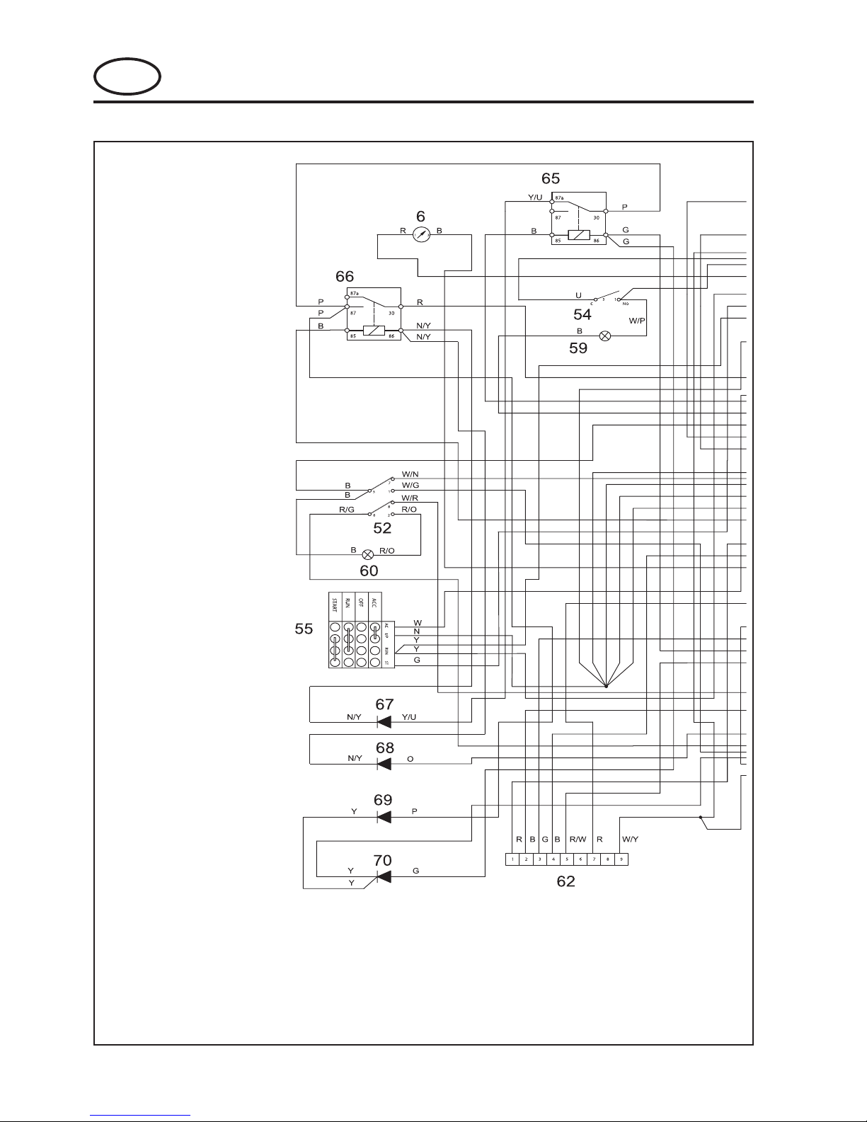
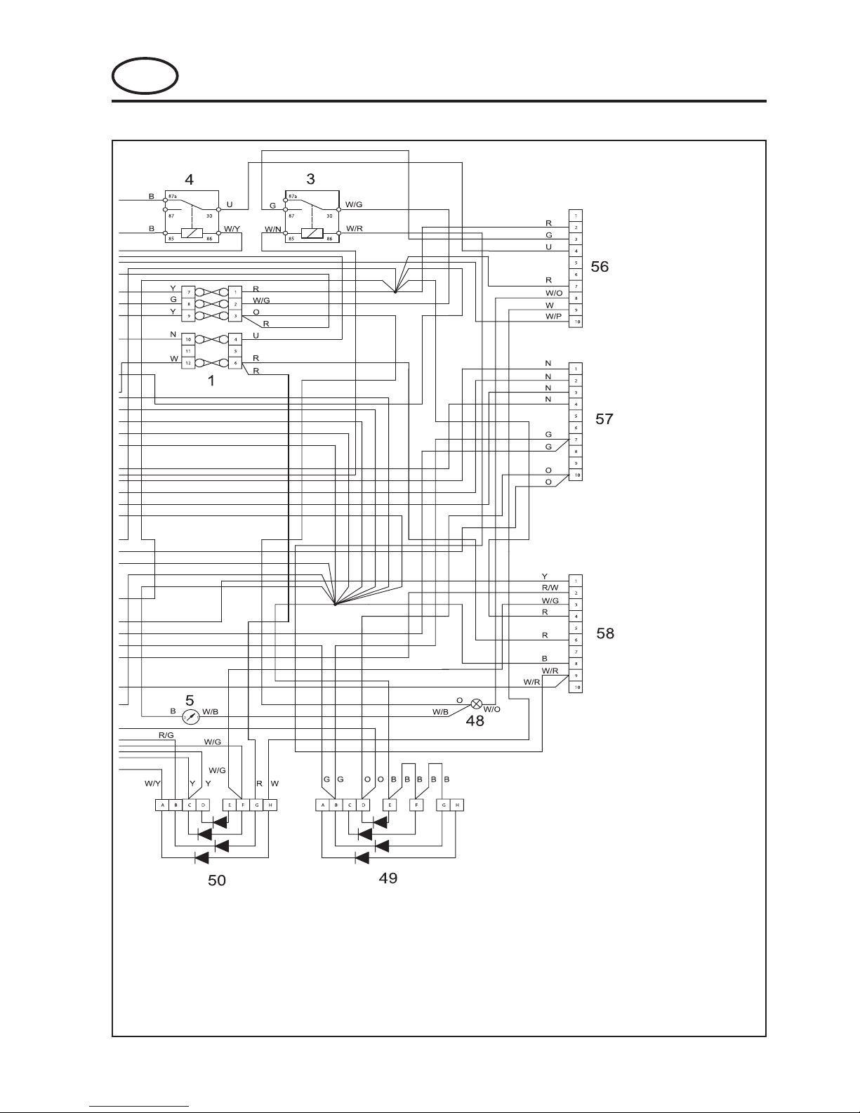
8.2 ELECTRICAL CIRCUIT MAIN HARNESS - GASOLINE

GB-31
JACOBSEN G-PLEX III Series: DN & DP
MAINTENANCE AND PARTS MANUAL
GB
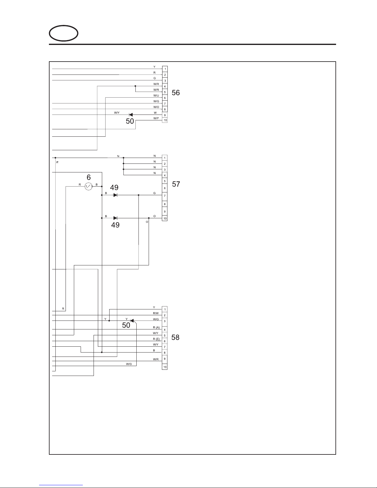
CABLE COLOUR CODE
R Red
G Green
O Orange
S Grey
B Black
W White
K Pink
P Violet
Y Yellow
UBlue
N Brown
BG Black Green
BO Black Orange
NU Brown Blue
WG White Green
WY White Yellow
7 SCHEMATICS
1 Starter Motor
2 Battery +ve Terminal
17 Backlap Switch
25 Alternator
27 Starter Solenoid Batt +ve Terminal
28 Starter Solenoid
29 Engine Kill
30 Oil Pressure Sender
32 Carburetor Solenoid
35 Solenoid Ground
36 Headlight
37 Headlight
38 Raise Solenoid
39 Lower Solenoid
40 Reel Solenoid
41 Seat Switch
56 Instrument Connector 1
57 Instrument Connector 2
58 Instrument Connector 3
59 Paddle Switch
60 Foot Switch
62 Parking Brake / Neutral Switch
GB-32
GB
JACOBSEN G-PLEX III Series: DN & DP
MAINTENANCE AND PARTS MANUAL
8.3 ELECTRICAL CIRCUIT CONTROL PANEL - GASOLINE
1 Fuse Box
3 Starter Relay
4 Ignition Relay
5 Hour Meter
6 Volt Meter
48 Oil Pressure Light
49 Diode Array 2
50 Diode Array 1
52 Reel Enable Switch
54 Headlight Switch
55 Key Switch
56 Instrument Connector
1
57 Instrument Connector
2
58 Instrument Connector
3
59 Headlight Switch Light
60 Reel Enable Switch
Light
62 Lift / Lower Modual
65 Raise Relay
66 Lower Relay
67 Diode
68 Diode
69 Diode
70 Diode
GB-33
JACOBSEN G-PLEX III Series: DN & DP
MAINTENANCE AND PARTS MANUAL
GB
CABLE COLOUR CODE
R Red
G Green
O Orange
S Grey
B Black
W White
K Pink
P Violet
Y Yellow
U Blue
N Brown
BG Black Green
BO Black Orange
NU Brown Blue
WG White Green
WY White Yellow
GB-34
GB
JACOBSEN G-PLEX III Series: DN & DP
MAINTENANCE AND PARTS MANUAL
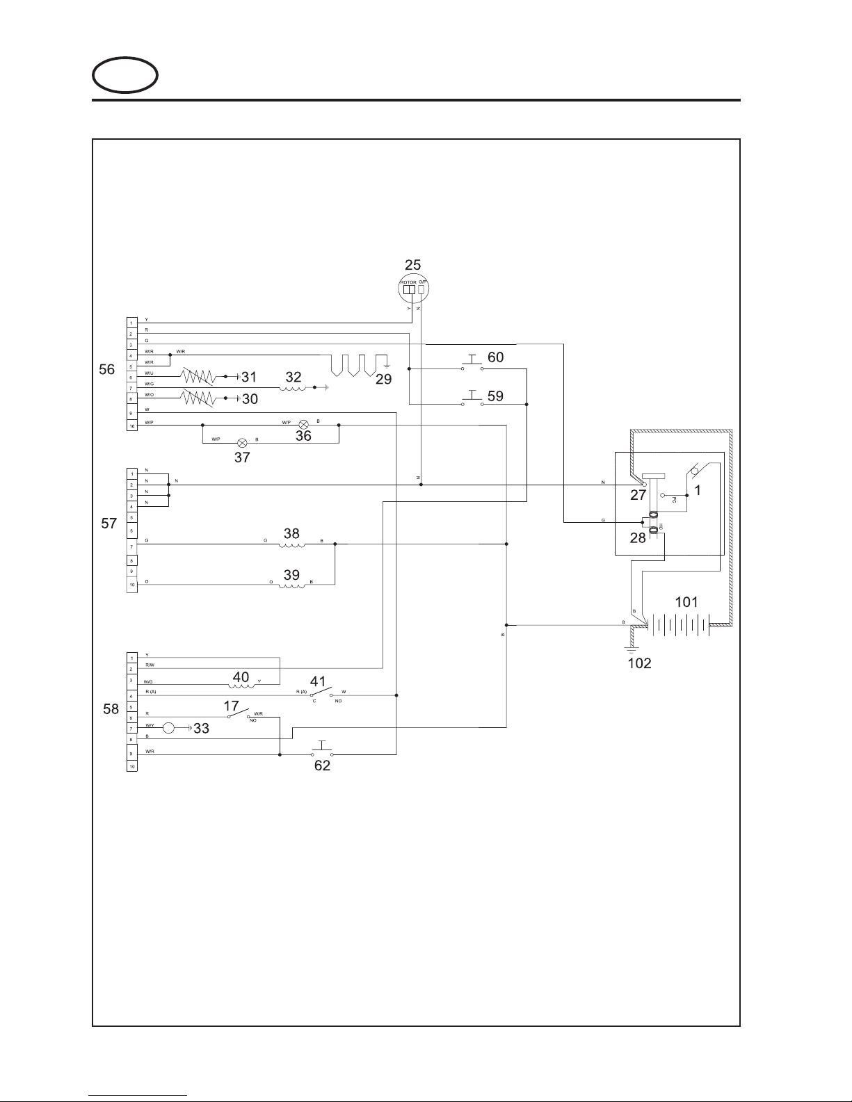
8.4 ELECTRICAL CIRCUIT MAIN HARNESS - DIESEL

GB-35
JACOBSEN G-PLEX III Series: DN & DP
MAINTENANCE AND PARTS MANUAL
GB
CABLE COLOUR CODE
R Red
G Green
O Orange
S Grey
B Black
W White
K Pink
P Violet
Y Yellow
UBlue
N Brown
BG Black Green
BO Black Orange
NU Brown Blue
WG White Green
WY White Yellow
1 Starter Motor
17 Backlap Switch
25 Alternator
27 Starter Solenoid Batt +ve Terminal
28 Starter Solenoid
29 Glow Plugs
30 Oil Pressure Sender
31 Water Temperature Sender
32 Fuel Solenoid
33 Fuel Pump
36 Headlight
37 Headlight
38 Raise Solenoid
39 Lower Solenoid
40 Reel Solenoid
41 Seat Switch
56 Instrument Connector 1
57 Instrument Connector 2
58 Instrument Connector 3
59 Paddle Switch
60 Foot Switch
62 Parking Brake / Neutral Switch
101 Battery
102 Battery Ground
GB-36
GB
JACOBSEN G-PLEX III Series: DN & DP
MAINTENANCE AND PARTS MANUAL
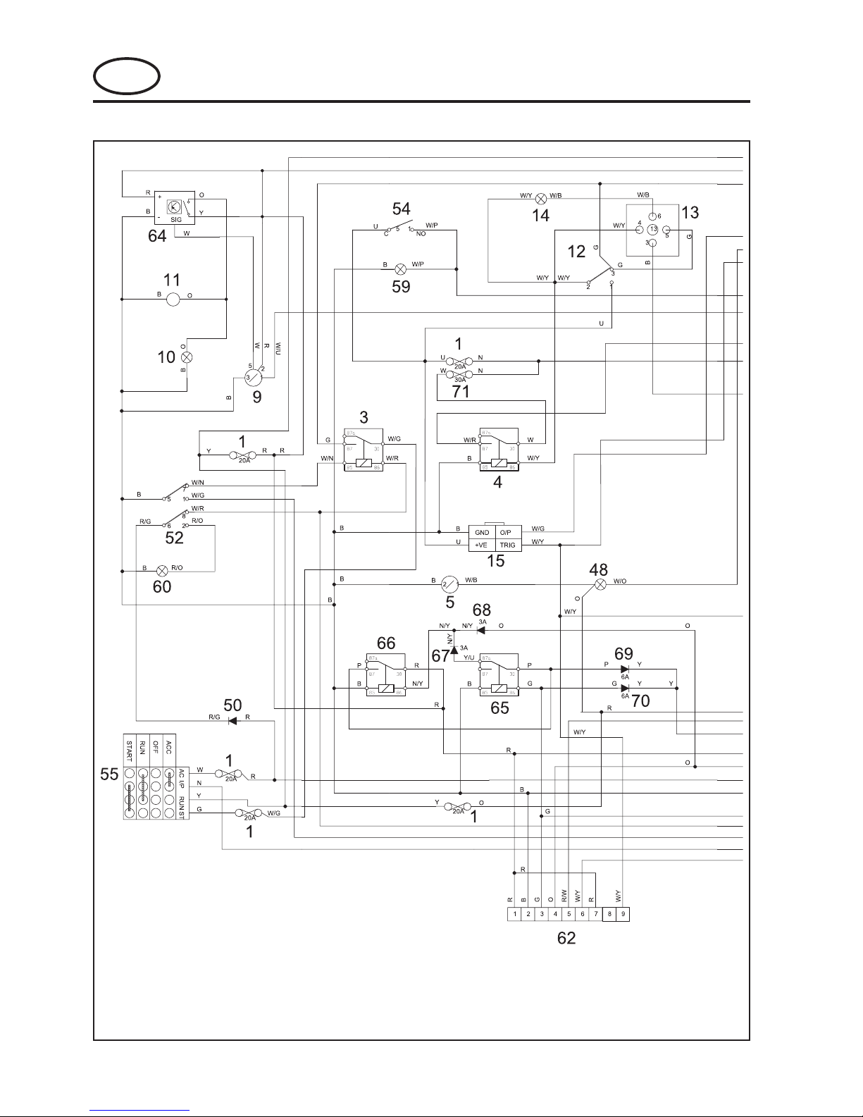
8.5 ELECTRICAL CIRCUIT CONTROL PANEL - DIESEL
GB-37
JACOBSEN G-PLEX III Series: DN & DP
MAINTENANCE AND PARTS MANUAL
GB
CABLE COLOUR CODE
R Red
G Green
O Orange
S Grey
B Black
W White
K Pink
P Violet
Y Yellow
U Blue
N Brown
BG Black Green
BO Black Orange
NU Brown Blue
WG White Green
WY White Yellow
1 Fuse 20Amp
3 Starter Relay
4 Ignition Relay
5 Hour Meter
6 Volt Meter
9 Water Temperature Gauge
10 Water Temperature Lamp
11 Water Temperature Buzzer
12 Preheat Switch
13 Preheat Timer
14 Preheat Lamp
15 Shut Down Timer
48 Oil Pressure Light
49 Diode Array 2
50 Diode Array 1
52 Reel Enable Switch
54 Headlight Switch
55 Key Switch
56 Instrument Connector 1
57 Instrument Connector 2
58 Instrument Connector 3
59 Headlight Switch Light
60 Reel Enable Switch Light
62 Lift / Lower Module
64 Water Temperature Gauge Relay
65 Raise Relay
66 Lower Relay
67 Diode
68 Diode
69 Diode
70 Diode
71 Fuse 30Amp

GB-38
GB
JACOBSEN G-PLEX III Series: DN & DP
MAINTENANCE AND PARTS MANUAL
NOTES

Parts-1
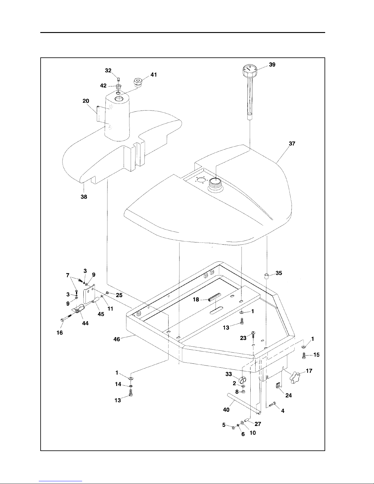
JACOBSEN G PLEX III Series: DN & DP
MAINTENANCE AND PARTS MANUAL
PARTS INDEX
1 CHASSIS AND COVERS ................................................................................... 3
2 POWER ASSY DIESEL ..................................................................................... 5
3 POWER ASSY GASOLINE ................................................................................ 7
4 RADIATOR (DIESEL) ......................................................................................... 9
5 AIR CLEANER (DIESEL) ................................................................................... 11
6 FUEL & HYDRAULIC RESERVOIRS & SUPPORT FRAME ............................... 13
7 HYDRAULIC TANK FITTINGS ........................................................................... 15
8 FUEL SYSTEM DIESEL .................................................................................... 17
9 FUEL SYSTEM GASOLINE ............................................................................... 19
10 OIL COOLER MOUNTING DIESEL .................................................................... 21
11 OIL COOLER MOUNTING GASOLINE .............................................................. 23
12 PUMP CONTROL LINKAGE ............................................................................. 25
13 HYDRAULIC PUMP AND VALVES - DIESEL ..................................................... 27
14 HYDRAULIC PUMP AND VALVES - GASOLINE ................................................ 29
15 HYDRAULIC LIFT CIRCUIT ............................................................................... 31
16 HYDRAULIC REEL CIRCUIT ............................................................................. 33
17 HYDRAULIC WHEEL DRIVE CIRCUIT ............................................................... 35
18 HYDRAULIC POWER STEERING ..................................................................... 37
19 CONTROL ARM ............................................................................................... 39
20 LIFT ASSEMBLY - FRONT CUTTING HEADS .................................................... 41
21 LIFT ASSEMBLY - REAR CUTTING HEAD ........................................................ 43
22 MOW / RAISE SWITCH AND SPEED CONTROL PEDAL ................................. 47
23 MOW SPEED CONTROL ................................................................................. 49
24 BRAKE PEDAL ................................................................................................. 51
25 SEAT ................................................................................................................ 53
26 DECALS ........................................................................................................... 55
27 CONTROL PANEL AND ELECTRICAL COMPONENTS DIESEL........................ 57
28 CONTROL PANEL AND ELECTRICAL COMPONENTS GASOLINE .................. 59
29 ELECTRICAL COMPONENTS DIESEL ............................................................. 61
30 ELECTRICAL COMPONENTS GASOLINE ........................................................ 63
31 WHEELS AND REAR HUB ................................................................................ 65
32 MOTOR MOUNTING ......................................................................................... 67
33 CUTTING HEAD ................................................................................................ 69
34 REAR ROLLERS .............................................................................................. 7 1
35 VERTICUT HEAD .............................................................................................. 73
36 REAR ROLLER & SCRAPER VERTICUT .......................................................... 75
37 ACCESORY - ROTARY REAR BRUSH 068643 ................................................ 77
38 FRONT & REAR ROLLS ................................................................................... 79
39 FRONT ROLL 2" SMOOTH & SCRAPER ......................................................... 81
40 TURF GROOMER ............................................................................................. 83
41 TURF GROOMER DRIVE ASSEMBLY ............................................................... 85
42 TURF GROOMER DRIVEN ASSEMBLY ............................................................ 87
43 TURF GROOMER BLADE ASSEMBLY .............................................................. 89
44 TURF GROOMER ROLLER ASSEMBLY ........................................................... 91
45 TURF GROOMER QUICK HEIGHT ADJUSTER ................................................. 93
46 GRASS CATCHER ............................................................................................ 95
47 NUMBERICAL INDEX ....................................................................................... 96

Parts-2
JACOBSEN G PLEX III Series: DN & DP
MAINTENANCE AND PARTS MANUAL
1 CHASSIS AND COVERS

Parts-3
* Not Illustrated
LIST OF PARTS
ITEM RANSOMES DESCRIPTION QTY REMARKS
PART NO
JACOBSEN G PLEX III Series: DN & DP
MAINTENANCE AND PARTS MANUAL
1 CHASSIS AND COVERS
1 450390 Washer M8 5
2 456110016 Screw, 1/4-20 x 3/4" 6
3 450411 Lockwasher M8 9
4 450120013 Nut, 1/4-20 16 (M6 - P/N 450323)
5 450410 Lockwasher M6 16
6 456110359 Screw, 5/16-18 x 1" 5
6 450192 Screw, M8 x 25, Hex 2 Used battery tray
7 450120021 Nut, 5/16-18 5
8 450389 Washer M6 6
9 523169 Tread, pedal, 1 131/2" x 3"(343 x 76mm)
10 523171 Tread, pedal, 1 8 3/4" x 6"(222 x 152mm)
11 523224 Bumper, rubber 2
12 A119003 Screw, 5/16-18 x 3/4" 4
13 A139305 Nut, 1/4-20 flange 4
14 A139301 Nut, 5/16-18 flange 2
15 800019 Screw, P.T.H., 1/4-20 x 1/2" 14 (M6 - P/N 450539)
16 800177 Screw, T.H., 5/16-18 x 3/4" 16
17 A149604 Rivet, pop, 1
18 825824 Retainer 1
19 835039 Fastener, snap 1
20 4132871 Clamp, battery 1 replaces 839391
21 840170.07 Box, tool/step 1
22 840171.07 Cover,box 1
23 840172 Hinge, box 3
24 MBG6052 Panel, floor, LEFT 1
25 842880.07 Panel, floor, RIGHT 1
26 MBG6471 Panel, foot, CENTER 1
27 842882.06 Panel, line cover 1
28 MBG6472 Panel, floor, CENTER 1
29 842932.06 Panel, control 1
30 843196.06 Bracket, lift valve 1
31 843402.07 Cover, battery 1
32 843404A.06 Bracket, fitting mount 1
33 843412 Bracket, Switch mounting 1 Diesel Only
34 843886 Cover 1
35 843887.07 Strap, cover 1
36 844076 Strap 1
37 844107 Tread, pedal, 1 25 1/2" x 5" (645 x 127mm)
38 893791.06 Frame, main 1
39 894237.06 Tray, battery 1
40 310854 Nut,jam,1-14 2
41 452000627 Washer, 1" i.d. 1
42 A203607 Bearing, Ball 2
43 892913.06 Fork 1
44 4132872 Battery Tray Cover Stop 1 replaces MBG5930.06
* 450369 Nutsert 4

Parts-4
JACOBSEN G PLEX III Series: DN & DP
MAINTENANCE AND PARTS MANUAL
2 POWER ASSY DIESEL

Parts-5
* Not Illustrated
LIST OF PARTS
ITEM RANSOMES DESCRIPTION QTY REMARKS
PART NO
JACOBSEN G PLEX III Series: DN & DP
MAINTENANCE AND PARTS MANUAL
2 POWER ASSY DIESEL
892258 Engine 1 Kubota D772-E
1 4124180 Manifold 1
* 4132107 Manifold Guard 1
* 4132108 Screw M6 x 8 2
2 452200134 Lockwasher 4
3 A109001 Screw,3/8-16x2 2
4 456110016 Screw, 1/4-20 x 3/4 8
5 4123644 Spacer 1
6 4124496 Gasket 2
7 450120013 Nut, 1/4-20 8
8 452200029 Lockwasher, 1/4 8
9 450192 Screw 3
10 450411 Lockwasher 3
11 450120039 Nut, 3/8-16 4
12 4124181 Muffler 1
13 450633 Screw 3
14 A682055 Screw, M10 -1.25 x 30mm 4
15 452692 Screw 4
16 452000326 Washer, 3/8 4
17 826218 Mount, motor 4
18 4124175 Muffler Guard 1
19 4123646 Muffler Bracket 1
20 001990399 U-Clamp 1
21 842539.06 Bracket, engine mount 2
22 842540.06 Bracket, engine rear 1
* MBG5275A Guard, Muffler Support 2
24 W148270 Sender,watertemperature 1
25 A691149 Housing, coupling and Hub 1
25a 844496 Hub 1
25b 844497 Coupling 1
28 120052 Lockwasher,#10 2
29 800296 Screw, #10-24 x 3/4 2
30 306531 Nut, #10-24 2
31 547610 Cable, control (throttle) 1
32 800868 Washer, polyethylene, 2
33 827821 Knob, ball 1
34 A109001 Screw, 3/8-16 x 2" 2
35 A119032 Screw,M10-1.25 x 20mm 2

Parts-6
JACOBSEN G PLEX III Series: DN & DP
MAINTENANCE AND PARTS MANUAL
3 POWER ASSY GASOLINE

Parts-7
* Not Illustrated
LIST OF PARTS
ITEM RANSOMES DESCRIPTION QTY REMARKS
PART NO
JACOBSEN G PLEX III Series: DN & DP
MAINTENANCE AND PARTS MANUAL
3 POWER ASSY GASOLINE
1 450388 Washer, M5 2
2 120166 Lockwasher,1/2" 2
3 450412 S.L.Washer, M12 4
4 4123564 Rear Engine Bracket 1
5 4123566 Engine Mount Plate 1
6 4117098 Muffler 1
7 2701768.8 Tailpipe 1
8 2701808 Throttle Control & Cable 1
9 4123773 Muffler Shield 1
10 450032 Screw, M10 x 50 2
11 2702239 Housing, Coupler & Adaptor 1
Coupler 1
Adaptor 1
12 2702384 Seal, Cooler 1 Up to Serial Number DN000xxx
12 4142825 Seal, Cooler 1 From Serial Number DN000xxx
13 4123676 Heat Shield 1
14 456110016 Screw, 1/4-20 x 3/4" 8
15 450120398 Nut, 3/8"-20 1
16 450120013 Nut, 1/4"-20 8
17 452200029 S.L.Washer, 1/4" 8
18 450017 Screw, M8 x 45 4
19 450376 Nut, M5, Staytite 2
20 450379 Nut, M10, Staytite 4
21 456110448 Screw, 3/8"-16 x 1/4" 4
22 450032 Screw, M10 x 50 2
23 453003341 Square Key, 1/4" x 1 3/4" 1
24 450529 Screw, M5 x 20, Pan Hd 2
25 450378 Nut, M8, Staytite 4
26 800770 Screw, 1/2"-13 x 3/4" 2
27 452692 Screw, M6 x 12, Taptite 1
28 450391 Washer, M10 10
29 001990399 Clamp 1
30 814065 Choke Cable (152cm) 1
32 451126 Screw, No.6 x 9.5, Rec. Pan Hd. 1
33 826218 Motor Mount 4
34 827821 Ball Knob 1
35 894103 Pump 1
547731 Service Kit 1
36 2701736 Engine, Briggs & Stratton 1 Model 350447 Up to DN000xxx
36 4142405 Engine, Briggs & Stratton 1 Model 356447 From DN000xxx
37 Gasket 2 Briggs & stratton
38 Screw 4 Briggs & stratton
* W48412 Clamp 1 Secures Harness to engine
Parts-8
JACOBSEN G PLEX III Series: DN & DP
MAINTENANCE AND PARTS MANUAL
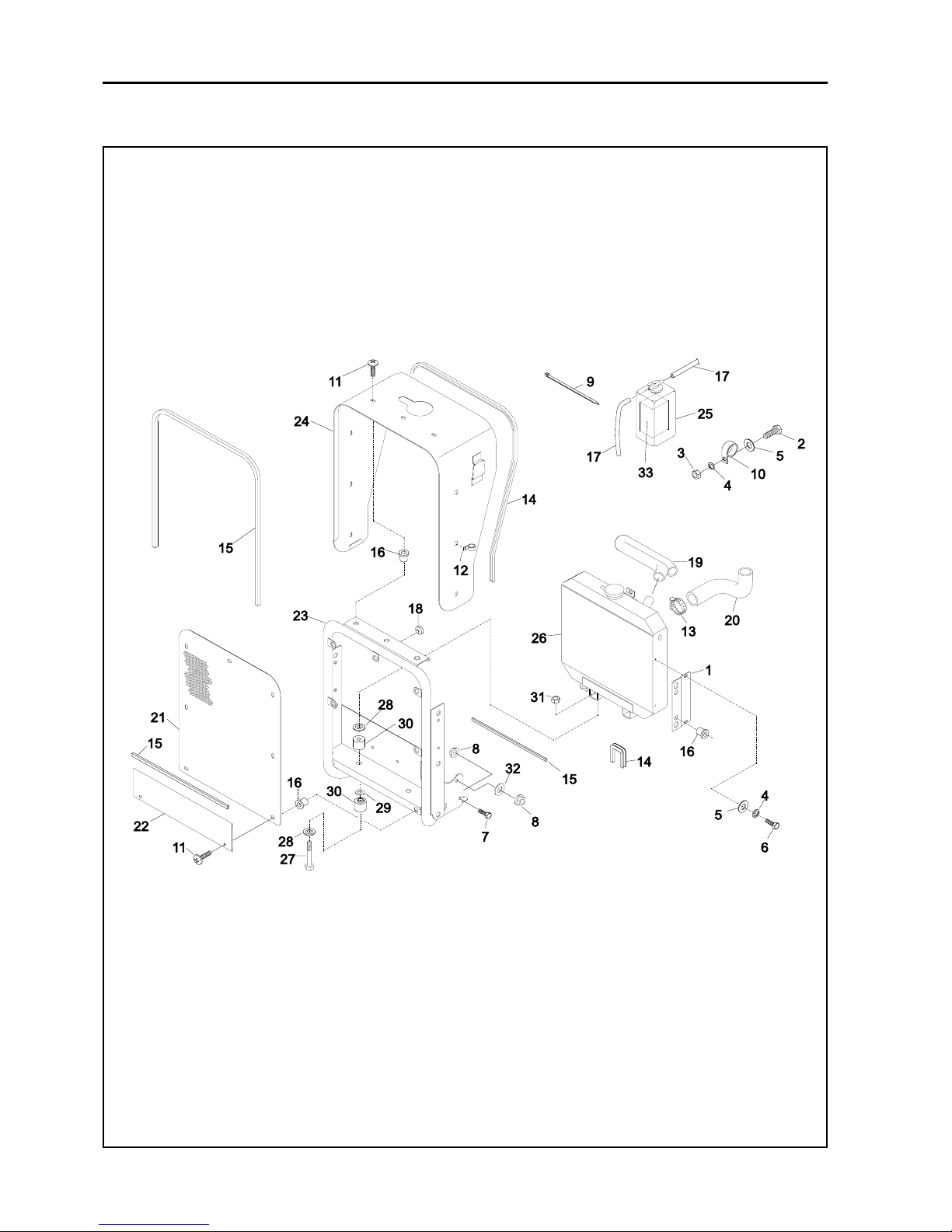
4 RADIATOR (DIESEL)

Parts-9
* Not Illustrated
LIST OF PARTS
ITEM RANSOMES DESCRIPTION QTY REMARKS
PART NO
JACOBSEN G PLEX III Series: DN & DP
MAINTENANCE AND PARTS MANUAL
4 RADIATOR (DIESEL)
1 841160.06 Bracket, radiator 2
2 456110016 Screw, 1/4-20 x 3/4" 1
3 450120013 Nut, 1/4-20 1
4 452200029 Lockwasher, 1/4" 5
5 452100019 Washer, 1/4" 5
6 450168 Screw, M6 x 16 mm 4
7 456110595 Screw, 3/8-16 x 3/4" 2
8 450120267 Nut, crowniock flange, 3/8-16.... 4
9 A199203 Tie, cable, 7 1/2" (191 mm) 3
10 523213 Clip 1
11 450551 Screw, P.T.H. 16
12 815058 Clamp 1
13 A192540 Clamp, tubing 4
14 821893 Trim, push-on, 12' (3.6M) As Reqd
15 830355 Weatherseal, 35' (1 0.6M). As Reqd
16 A139924 Nut, isolation M8 16
17 835805 Hose, overflow 4' (1 .2M) . As Reqd
18 810149 Bumper, rubber 1
19 A912176 Hose, radiator, top 1
20 839953 Hose, radiator, bottom 1
21 839973.07 Panel, screen 1
22 840062.07 Panel, radiator 1
23 894077.06 Frame, radiator 1
23 4131290 Frame radiator 1 From M/C DP000486
24 892633.06 Cover, radiator 1
25 15531-72-403 Bottle, overflow 1 Ex Kubota
26 16676-72-061 Radiator 1 Ex Kubota
27 450034 Screw, M10 x 60 mm 2
28 15111-72202 Washer 4 Ex Kubota
30 15111-72181 Bushing, rubber 2 (with spigot) Ex Kubota
30 15111-72191 Bushing, Rubber 2 Ex Kubota
31 450325 Nut, M10 -1.25 2
32 452000326 Washer, 3/8" 2
33 523930 Foam 1
Parts-10
JACOBSEN G PLEX III Series: DN & DP
MAINTENANCE AND PARTS MANUAL
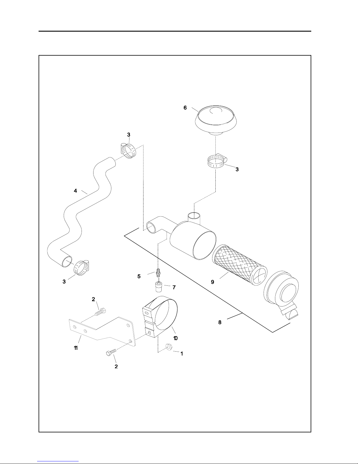
5 AIR CLEANER (DIESEL)

Parts-11
* Not Illustrated
LIST OF PARTS
ITEM RANSOMES DESCRIPTION QTY REMARKS
PART NO
JACOBSEN G PLEX III Series: DN & DP
MAINTENANCE AND PARTS MANUAL
5 AIR CLEANER (DIESEL)
1 A139322 Nut, flange crownlock 5/16-18 2
2 456110359 Screw, 5/16-18 x 1" 4
3 A192557 Clamp, hose, worm drive 3
4 844045 Hose, air intake 1
5 840346 Adaptor, gauge 1
6 4132265 Hood, inlet 1 Replaces 840347
* 4132266 Sleeve 1
7 888036 Gauge, restriction 1
8 893182 Filter,air,complete 1
9 0840352 Element, air filter 1
10 A819028 Bracket, filter 1
11 844044.06 Bracket, air filter 1
Parts-12
JACOBSEN G PLEX III Series: DN & DP
MAINTENANCE AND PARTS MANUAL
6 FUEL & HYDRAULIC RESERVOIRS & SUPPORT FRAME

Parts-13
* Not Illustrated
LIST OF PARTS
ITEM RANSOMES DESCRIPTION QTY REMARKS
PART NO
JACOBSEN G PLEX III Series: DN & DP
MAINTENANCE AND PARTS MANUAL
1 450390 Washer,M8 4
2 450409 Lockwasher,M5 1
3 452200134 Lockwasher, 3/8 8
4 A109011 Screw, 1/420 x 1 1/2 1
5 450120013 Nut, 1/420 1
6 452200029 Lockwasher, 1/4 1
7 456110066 Screw,3/816x1 4
* 450214 Screw M10 x 25 4
8 A139325 Nut, #10 1
9 450391 Washer, M10 8
10 452100019 Washer, 1/4 8
11 450392 Washer, M12 2
14 450411 Lockwasher, M8 2
15 452390 Bolt, M8 x 30 1
16 450061 Screw, M12 x 120 2
17 A907947 Knob, nut, M8 2
18 821893 Trim, pushon, 12(3.7 M) AR
20 158122 Tubing, polyurethane, 1
23 A119109 Screw,#1024x3/4 1
24 A907948 Nut, Speed M8 2
25 450380 Nut, M12 2
27 820529 Spacer 1
32 836852 Breather 1
33 838225 Clip 1
35 839876 Bushing 1
37 843267 Tank, fuel 1
38 843268 Reservoir, oil 1
39 843401 Cap, fuel with gauge 1
40 843696 Tube, support, 8 (203 mm) 1
41 843885 Plug 1
42 844080 Adapter 1
44 894352.06 Hinge, lower 1
45 894353.06 Hinge, upper 1
46 894354.06 Frame, tank support 1
6 FUEL & HYDRAULIC RESERVOIRS & SUPPORT FRAME
Parts-14
JACOBSEN G PLEX III Series: DN & DP
MAINTENANCE AND PARTS MANUAL
7 HYDRAULIC TANK FITTINGS

Parts-15
* Not Illustrated
LIST OF PARTS
ITEM RANSOMES DESCRIPTION QTY REMARKS
PART NO
JACOBSEN G PLEX III Series: DN & DP
MAINTENANCE AND PARTS MANUAL
47 843556 Elbow, 90, 11/16 x 1/2 NPT 1
48 843557 Elbow, 90, 3/4 x 3/4 NPT 1
49 843558 Elbow, 90, 1 x 1 NPT 1
50 148231 Fifting, 3/16, elbow 1
51 48310 Bushing 1
52 836206 Clamp 1
53 869037 Fitting, 3/4 x 3/4 NPT 1
7 HYDRAULIC TANK FITTINGS
Parts-16
JACOBSEN G PLEX III Series: DN & DP
MAINTENANCE AND PARTS MANUAL
8 FUEL SYSTEM DIESEL

Parts-17
* Not Illustrated
LIST OF PARTS
ITEM RANSOMES DESCRIPTION QTY REMARKS
PART NO
JACOBSEN G PLEX III Series: DN & DP
MAINTENANCE AND PARTS MANUAL
8 FUEL SYSTEM DIESEL
1 450390 Washer, M8 1
2 450409 Lockwasher, M5 5
3 450411 Lockwasher, M8 2
4 A109043 Screw,5/16-18x23/4" 1
5 450120021 Nut, 5/16-18 1
6 A119004 Screw, #10-24 x 1/2" 5
7 450191 Screw,M8-1.25x20mm 1
8 A192516 Clamp, hose As Reqd
9 A912175 Hose, fuel, 5/16 As Reqd
* A912182 Hose - Fuel 3/16 1
10 5001182 Filter, fuel 1
11 829954 Gasket 1
12 838154 Bracket,fuelpumpmount 1
13 839975.06 Bracket, mounting, fuel filter 1
14 843267 Tank, fuel 1
15 843401 Cap, fuel wigauge 1
16 4126806 Pump,fuel 1
17 894256 Pickup, fuel 1
18 Filter Assembly, fuel 1 Ex Kubota
19 840161 Element, fuel filter 1
20 817320 Clamp 1
21 450190 Screw, M8 x l6mm 1
22 450390 Washer, M8 1

Parts-18
JACOBSEN G PLEX III Series: DN & DP
MAINTENANCE AND PARTS MANUAL
9 FUEL SYSTEM GASOLINE

Parts-19
* Not Illustrated
LIST OF PARTS
ITEM RANSOMES DESCRIPTION QTY REMARKS
PART NO
JACOBSEN G PLEX III Series: DN & DP
MAINTENANCE AND PARTS MANUAL
9 FUEL SYSTEM GASOLINE
1 843267 Tank, fuel 1
2 843401 Cap, fuel with gauge 1
3 894256 Pickup, fuel 1
4 829954 Gasket 1
5 800271 Screw, #10-24 x 1/2" 5
6 120052 Lockwasher, #10 6
7 838491 Cap, fuel line 1
8 001921740 Hose, fuel, 30" 1
9 001925160 Clamp, hose 2

Parts-20
JACOBSEN G PLEX III Series: DN & DP
MAINTENANCE AND PARTS MANUAL
10 OIL COOLER MOUNTING DIESEL

Parts-21
* Not Illustrated
LIST OF PARTS
ITEM RANSOMES DESCRIPTION QTY REMARKS
PART NO
JACOBSEN G PLEX III Series: DN & DP
MAINTENANCE AND PARTS MANUAL
10 OIL COOLER MOUNTING DIESEL
1 450390 Washer 4
6 A109018 Screw, 5/16-18 x 1 3/4" 4
6 450017 Bolt, M8 X 45 4 2001 onwards
12 839501 Mounting block, oil cooler 4
18 842916 Cooler, oil 1
19 523768 Adapter, elbow 90 1
20 001925570 Clamp, hose 1
21 839807 Adapter, straight 1
22 W158007-02 Adapter,elbow9O
0
25 843930 Hose, hydraulic, 3/4" id x 66" 1 (1 9mm id, x 1 .68M) (diesel)
26 843925 Hose, hydraulic, 1/2" id x 53" 1 (1 3mm id, x 1 .35M) (diesel)

Parts-22
JACOBSEN G PLEX III Series: DN & DP
MAINTENANCE AND PARTS MANUAL
11 OIL COOLER MOUNTING GASOLINE

Parts-23
* Not Illustrated
LIST OF PARTS
ITEM RANSOMES DESCRIPTION QTY REMARKS
PART NO
JACOBSEN G PLEX III Series: DN & DP
MAINTENANCE AND PARTS MANUAL
11 OIL COOLER MOUNTING GASOLINE
1 450390 Washer, M8 6
2 4123565 Cover, air intake 1 Up to serial No DN000xxx
2 4140585 Cover, air intake 1 From serial No DN000xxx
3 4123664 Housing, oil cooler 1 Up to serial No.DN000xxx
3 4140587 Housing, oil cooler 1 From serial No DN000xxx
4 4123550 Angle, Cover 2
5 4123563 Angle, screen 2
6 2702424 Hose, hydraulic, 3/4" x 62" 1 (19mm x 559mm)
7 2702425 Hose, hydraulic, 1/2" x 41" 1 (13mm x 914mm)
8 450011 Lockwasher, M8 2
9 450004 Screw, M8 x 45 4
10 450191 Screw, M8 x 20 2
11 450389 Washer, M6 6
12 523768 Adapter, elbow 90° 1
13 450191 Screw, M8 x 20 1
14 450377 Nut, M6 Nyloc 4
15 001496044 Rivet, pop, 13/64" x 3/8" 1
16 452436 Nut, 2
17 379050522 Trim, push-on, 12' (3.6M) AR
18 469021633 Clamp, tube 2
19 002989380 Weather seal AR
20 835039 Fastener, snap 1
21 001925400 Clamp, hose 2
22 839501 Mounting block, oil cooler 4
23 839807 Adapter, straight 1
24 839821 Adapter, elbow 90° 1
25 842916 Cooler, oil 1
26 843823 Screen, cooler 1
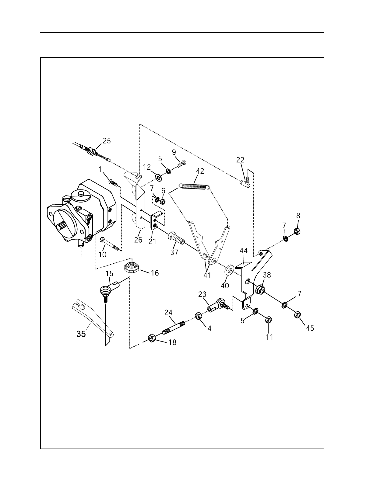
Parts-24
JACOBSEN G PLEX III Series: DN & DP
MAINTENANCE AND PARTS MANUAL
12 PUMP CONTROL LINKAGE

Parts-25
* Not Illustrated
LIST OF PARTS
ITEM RANSOMES DESCRIPTION QTY REMARKS
PART NO
JACOBSEN G PLEX III Series: DN & DP
MAINTENANCE AND PARTS MANUAL
12 PUMP CONTROL LINKAGE
1 456110016 Screw, 1/4-20 x 3/4 1
4 45002053 Nut, 5/16-24 2
5 450411 Lockwasher 4
6 450020037 Nut, 1/4 2
7 452200029 Lockwasher, 1/4 2
8 A139912 Nut, 1/4-28 Nyloc 1
9 456110359 Screw,5/16-18x1 2
10 451030269 Screw,5/16-24 x 2 1/2 1
11 450020053 Nut, 5/16-24 1
12 452000326 Washer, 3/8 1
15 523253 End, control rod 1
16 523409 Knob 1
18 450020249 Nut, 5/16-24 (left hand thread) 1
21 4126343 Stop, neutral control arm 1
22 831518 Ball Joint 1
23 831586 Ball Joint 1
24 838093 Rod, threaded, 5/16-24 x 2 1/2".. 1
25 842999 Cable, control 1
26 843119.06 Bracket,pumpcontrol 1
35* MBG6344 Control Arm 1
* 450016 M8x40 Bolt 1 Used Item 35
* 450378 M8 Nyloc Nut 1 Used Item 35
* 451457 M6 Spirol Pin 1 Used Item 35
37 523492 Bushing 1
38 800559 Nut, crownlock flange, 1/2-20 1
40 809180 Washer, 7/16" 1
41 827320 Arm, spring retainer 2
42 840476 Spring 1
44 843117 Arm,control 1
45 450020257 Nut Hex 5/16-24 Thin 1
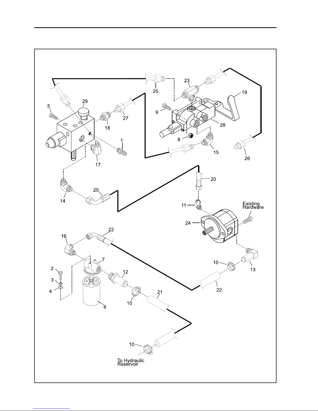
Parts-26
JACOBSEN G PLEX III Series: DN & DP
MAINTENANCE AND PARTS MANUAL
13 HYDRAULIC PUMP AND VALVES - DIESEL

Parts-27
* Not Illustrated
LIST OF PARTS
ITEM RANSOMES DESCRIPTION QTY REMARKS
PART NO
JACOBSEN G PLEX III Series: DN & DP
MAINTENANCE AND PARTS MANUAL
13 HYDRAULIC PUMP AND VALVES - DIESEL
1 W178079 Fitting,test 1
2 456110498 Screw, 1/4-20 x 1/4" 2
3 452200029 Lockwasher, 1/4" 1
4 452100019 Washer, 1/4" 2
5 450213 Screw,M1O-1.5x20 2
6 4136798 Filter, hydraulic 1
7 547818 Head, hydraulic filter 1
8 A139305 Nut, 1/4-20 3
9 A109011 Screw, 1/4-20 x 11/2" 3
10 A192570 Clamp, hose 23-70 3
11 W158059-01 Adaptor, 450 1
12 839556 Fitting, adaptor, straight 1
13 839557 Fitting, adaptor, 90 1
14 158059-03 Fitting, adaptor, 45 1
15 W158007-03 Adaptor, elbow, 90 1
16 839820 Adaptor, elbow, 90 1
17 W158007-02 Adaptor, elbow, 90 1
18 W158006-05 Adaptor, straight 1
19 843411 Lever, valve 1
20 843923 Hose, hyd. 1/2" i.d. x 28" 1 (13 mm i.d.x711 mm)
21 843931 Hose, hyd. 1" i.d. x 15" 1 (25.4mmi.d.x381 mm)
22 843932 Hose, hyd. 1" i.d. x 26 1/2" 1 (25.4mmi.d.x673mm)
23 844071 Tee, branch 1
24 2701711 Pump, hydraulic 1
* 2702707 Service Kit As Reqd
25 894244 Line, hydraulic 1
26 894245 Line, hydraulic 1
27 894248 Line, hydraulic 1
28 2208047 Valve, 4 way 3 position 1
29 2208146 Valve, reel drive 1
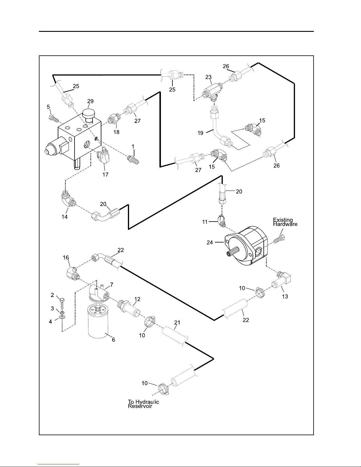
Parts-28
JACOBSEN G PLEX III Series: DN & DP
MAINTENANCE AND PARTS MANUAL
14 HYDRAULIC PUMP AND VALVES - GASOLINE

Parts-29
* Not Illustrated
LIST OF PARTS
ITEM RANSOMES DESCRIPTION QTY REMARKS
PART NO
JACOBSEN G PLEX III Series: DN & DP
MAINTENANCE AND PARTS MANUAL
1 W178079 Fitting,test 1
2 456110498 Screw, 1/4-20 x 1/4" 2
3 452200029 Lockwasher, 1/4" 1
4 452100019 Washer, 1/4" 2
5 450213 Screw,M1O-1.5x20 2
6 4136798 Filter, hydraulic 1
7 547818 Head, hydraulic filter 1
10 A192570 Clamp, hose 23-70 3
11 W158059-01 Adaptor, 450 1
12 839556 Fitting, adaptor, straight 1
13 839557 Fitting, adaptor, 90 1
14 158059-03 Fitting, adaptor, 45 1
15 4124349 Adaptor, elbow, 90 2
16 839820 Adaptor, elbow, 90 1
17 W158007-02 Adaptor, elbow, 90 1
18 W158006-05 Adaptor, straight 1
19 4124173 Tube 1
20 843923 Hose, hyd. 1/2" i.d. x 28" 1 (13 mm i.d.x711 mm)
21 843931 Hose, hyd. 1" i.d. x 15" 1 (25.4mmi.d.x381 mm)
22 843932 Hose, hyd. 1" i.d. x 26 1/2" 1 (25.4mmi.d.x673mm)
23 002540080 Tee, branch 1
24 2701711 Pump, hydraulic 1
* 2702707 Service Kit As Reqd
25 894244 Line, hydraulic 1
26 894245 Line, hydraulic 1
27 4124172 Hose, hydraulic 1
29 2208146 Valve, reel drive 1
14 HYDRAULIC PUMP AND VALVES - GASOLINE
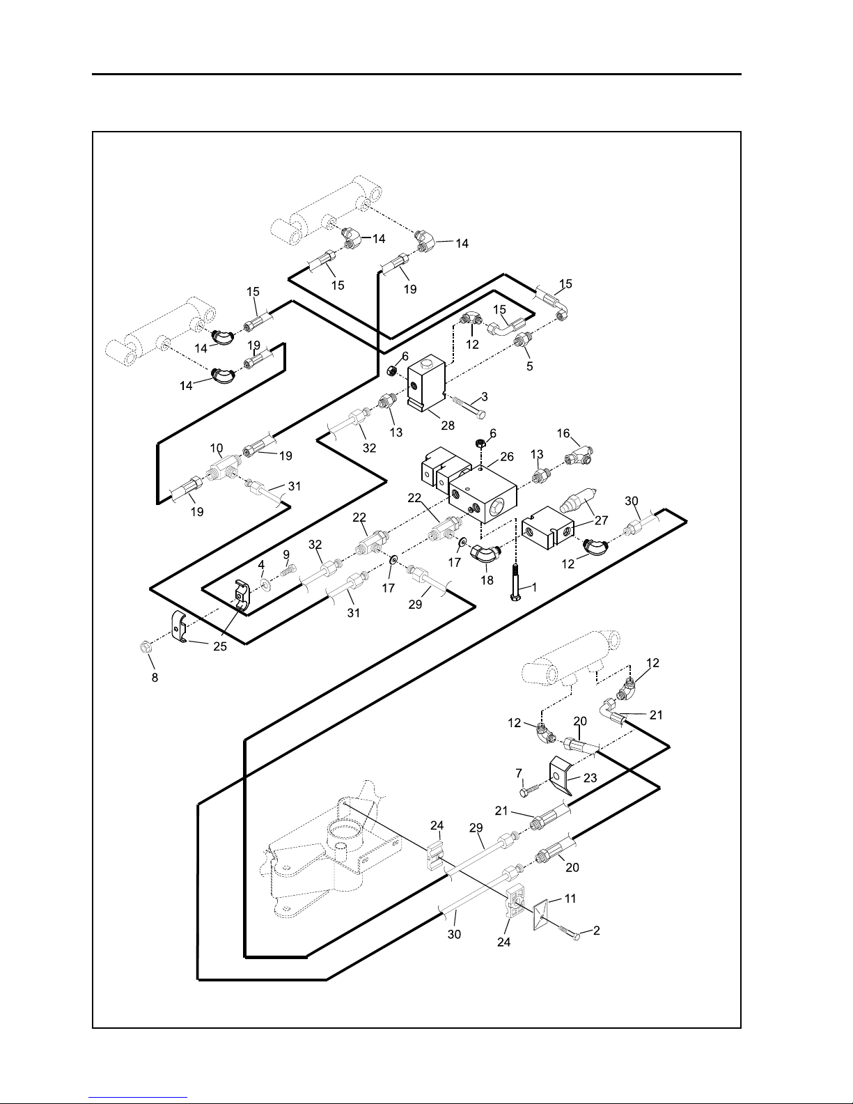
Parts-30
JACOBSEN G PLEX III Series: DN & DP
MAINTENANCE AND PARTS MANUAL
15 HYDRAULIC LIFT CIRCUIT

Parts-31
* Not Illustrated
LIST OF PARTS
ITEM RANSOMES DESCRIPTION QTY REMARKS
PART NO
JACOBSEN G PLEX III Series: DN & DP
MAINTENANCE AND PARTS MANUAL
15 HYDRAULIC LIFT CIRCUIT
1 451112681 Screw, 1/4-20 x 2" 2
2 A109018 Screw, 5/16-18 x 1 3/4" 1
3 451112681 Screw, 1/4-20 x 2" 2
4 452100019 Washer, 1/4" 2
5 W158006-04 Adapter, straight 1
6 A139305 Nut, 1/4-20 4
7 456110391 Screw, 5/16-18 x 5/8" 1
8 A139908 Nut, 1/4-20, flange lock 1
9 456010941 Screw, 1/4-20 x 11/4" 1
10 W158011-01 Tee, union 3
11 837736 Plate, clamp cover 2
12 W158007-01 Adaptor, elbow 90° 3
13 W158006-01 Adaptor, straight 1
14 A252501 Adaptor, elbow, 90° 4
15 839837 Hose, hydr. 1/4" i.d. x 10 1/2" 2 (6mmi.d.x267mm)
16 A249849 Tee, 0-ring 1
17 841522 Disk, orifice 2
18 841700 Adaptor, elbow, 90° 1
19 843908 Hose, hydraulic 1/4 ID x 10 5/8" 2 (6mm lD x 27Omm)
20 843916 Hose, hydraulic 3/8 ID x 39" 1 (9.5mm lD x 99l mm)
21 843917 Hose, hydraulic 3/8 ID x 39" 1 (9.Smm lD x 99lmm)
22 158056-02 Tee, run 2
23 844215 Clamp, tube 1
24 844218 Set, clamp 3/8" 1
25 844219 Clamp, tube 3/8" 1
26 894181 Valve,solenoid 4way 3pos 1
27 4121789 Valve, Bi-directional, Relief 1 Savery: CR1--28B-6T-N-24
* 4125159 Seal Kit A/R
28 894184 Valve, dividercombiner 1
* MBG5790 Bolt Strap 1
29 894240 Line assembly, hydraulic 1
30 894241 Line assembly, hydraulic 1
31 894242 Line assembly, hydraulic 1
32 894243 Line assembly, hydraulic 1
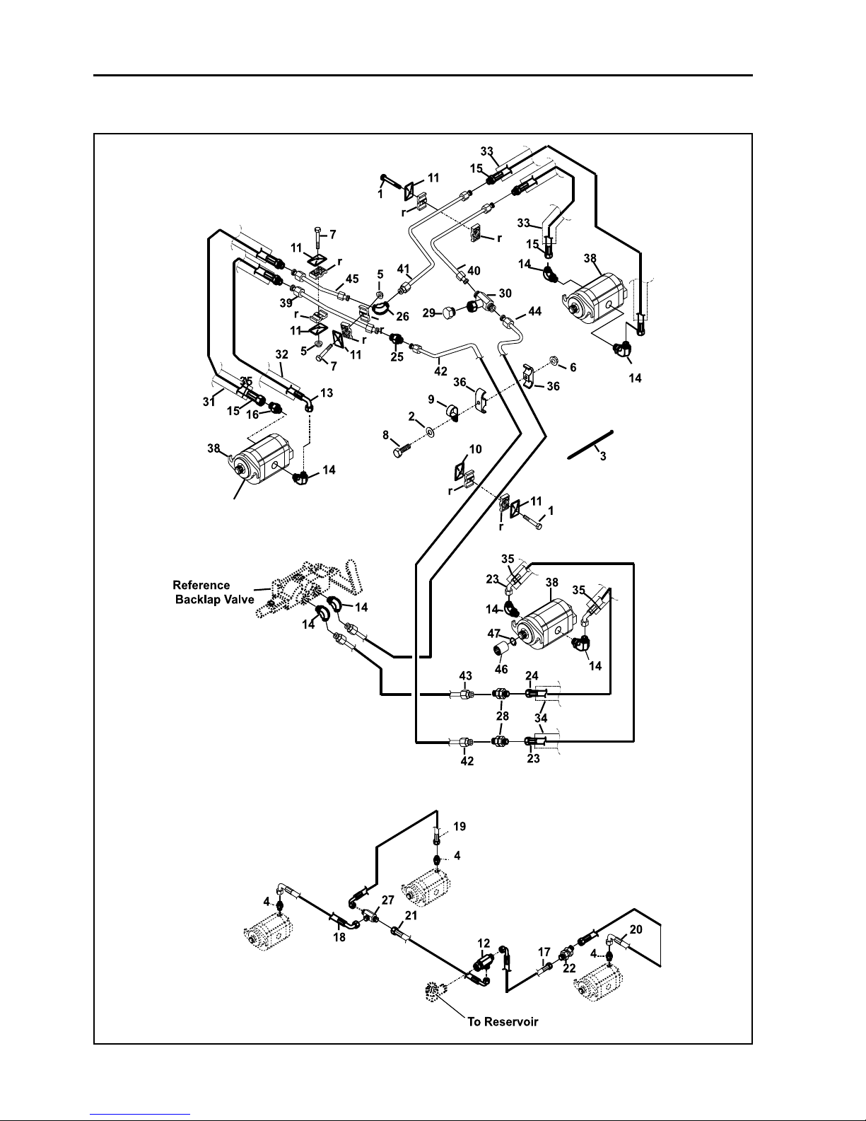
Parts-32
JACOBSEN G PLEX III Series: DN & DP
MAINTENANCE AND PARTS MANUAL
16 HYDRAULIC REEL CIRCUIT

Parts-33
* Not Illustrated
LIST OF PARTS
ITEM RANSOMES DESCRIPTION QTY REMARKS
PART NO
JACOBSEN G PLEX III Series: DN & DP
MAINTENANCE AND PARTS MANUAL
16 HYDRAULIC REEL CIRCUIT
1 450018 Screw,M8 x 50 2
2 452100019 Washer 1/4 1
3 680001941 Tie,cable AsReqd
4 A251500 Adapter, straight 3
5 452436 Nut, crownlock flange, M8 2
6 A139912 Nut, crowniock, 1/4-20 1
7 450020 Screw, flange M8 x 60 2
8 456010941 Screw, flange, 1/4-20 x 11/4" 1
9 814924 Clamp, hose 1
10 837735 Plate,twinweld 1
11 837736 Plate, clamp cover 5
12 A249840 Tee, O-nng 1
13 839814 Hose, hyd. 1/2" i.d. x 38" 1 (l3mm i.d.x 965mm)
14 W158007-02 Adaptor, elbow, 900 7
15 841673 Hose, hyd. 1/2" i.d. x 34" 3 (13 mm i.d.x864 mm)
16 W158006-05 Adaptor, straight 1
17 842830 Hose, hyd. 1/4" i.d. x 22" 1 (6mm i.d.x 559mm)
18 843909 Hose, hyd. 1/4" i.d. x 40 1/2" 1 (6mmi.d.x 1.03M)
19 843910 Hose, hyd. 1/4" i.d. x 49" 1 (6mmi.d.x 1.245M)
20 843911 Hose, hyd. 1/4" i.d. x 47 1/2" 1 (6mm i.d.x 1.21 M)
21 843913 Hose, hyd. 1/4" i.d. x 76" 1 (6mm i.d.x 1.93M)
22 843915 Union,bhead45
0
1
23 843921 Hose, hyd. 1/2" i.d. x 47 1/2" 1 (l3mm i.d.x 1.21 M)
24 843922 Hose, hyd. 1/2" i.d. x 43 1/4" 1 (l3mm i.d.x 1.1 M)
25 843989 Union, male 1
26 843991 Elbow, male 1
27 A259009 Tee, bhead 1
28 844072 Union, bulkhead 2
29 844078 Plug 1
30 844082 Tee, branch I
31 844083 Sleeve, nylon, 1 7/8" x 38" 1 (48mm x 965mm)
32 844084 Sleeve, nylon, 1 7/8" x 43" 1 (48 mm x 1.1M)
33 844085 Sleeve, nylon, 1 7/8" x 52" 2 (48mm x 1.32M)
34 844214 Sleeve, nylon, 1 7/8" x 48" 2 (48mm x 1.22M)
35 844216 Clamp, hose 8
36 844217 Clamp,tube 1
37 892418 Set, clamp hydraulic 4
38 2701710 Motor, reel drive 3
* 2702706 Service Kit As Reqd
39 894129 Line, hydraulic 1
40 894130 Line, hydraulic 1
41 894131 Line, hydraulic 1
42 894246 Line, hydraulic 1
43 894247 Line, hydraulic 1
44 894249 Line, hydraulic 1
45 894254 Line, hydraulic 1
46 J337370 Coupling, drive 3 (Jacobsen Cutting Unit)
47 800810 Ring, internal retaining 3

Parts-34
JACOBSEN G PLEX III Series: DN & DP
MAINTENANCE AND PARTS MANUAL
17 HYDRAULIC WHEEL DRIVE CIRCUIT

Parts-35
* Not Illustrated
LIST OF PARTS
ITEM RANSOMES DESCRIPTION QTY REMARKS
PART NO
JACOBSEN G PLEX III Series: DN & DP
MAINTENANCE AND PARTS MANUAL
17 HYDRAULIC WHEEL DRIVE CIRCUIT
1 450424 Lockwasher, M12 8
2 450054 Screw,M12 x 170 8
3 W158058-01 Fitting, adaptor, 900 1
4 456110016 Screw, 1/4-20 x 3/4" 2
5 452200029 Lockwasher, 1/4" 2
6 450016 Bolt- M8 x 40 1
7 452100019 Washer, 1/4" 2
8 4136798 Filter, hydraulic oil 1
9 W158007-05 Adaptor, elbow, 90° 1
10 A254005 Adaptor, tee 2
11 523768 Adaptor, elbow, 90° 1
12 547818 Head,filter 1
13 A192570 Clamp, hose 6
14 837735 Plate, twin weld, M8 1
15 837736 Plate,clamp cover 1
16 837737 Set, clamp, hydraulic 1
17 837753 Adaptor, elbow, 90° 1
18 A253501 Adaptor, elbow, 45° 4
19 839557 Fitting, adaptor, elbow, 90° 1
20 A259008 Adaptor, elbow, 90° 1
21 843914 Hose, hydraulic, 3/4" i.d. x 17" 1 (l9mmi.d.x432mm)
22 843926 Hose, hydraulic, 1/2" i.d. x 16 3/4" 1 (l3mmi.d.x425mm)
23 843927 Hose, hydraulic, 1/2" i.d. x 18 1/2" 1 (l3mmi.d.x47Omm)
24 843928 Hose, hydraulic, 3/4" i.d. x 22 1/2" 2 (l9mmi.d.x572mm)
25 843933 Hose, hydraulic, 1" i.d. x 12 3/4" 1 (25.4mmi.d.x324mm)
26 W158006-07 Connector 2
27 W158056-01 Tee, run 1
28 A256803 Cap 1
29 4115024 Motor, hydraulic HOS 1
30 800777 Key, woodruff, 5/16" x 1" 1
31 800778 Nut, 1-20 1 Torque 220Nm
* 891910 Kit, service As Reqd
32 892381 Motor, hydraulic 1
30 800777 Key, woodruff, 5/16" x 1" 1
31 800778 Nut, 1-20 1 Torque 220Nm
* 891910 Kit, service As Reqd
33 894103 Pump, hydraulic 1
* 547731 eKit, service ... As Reqd
34 894250 Line, hydraulic, bottom (left) 1
35 894251 Line, hydraulic, top (top) 1
36 894252 Line, hydraulic, bottom (right) .... 1
37 894253 Line, hydraulic, top (right) 1
38 800770 Screw, 1/2-13 x 1 3/4" 2
39 452200176 Lockwasher, 1/2" 2

Parts-36
JACOBSEN G PLEX III Series: DN & DP
MAINTENANCE AND PARTS MANUAL
18 HYDRAULIC POWER STEERING

Parts-37
* Not Illustrated
LIST OF PARTS
ITEM RANSOMES DESCRIPTION QTY REMARKS
PART NO
JACOBSEN G PLEX III Series: DN & DP
MAINTENANCE AND PARTS MANUAL
18 HYDRAULIC POWER STEERING
1 452200176 Lockwasher, 1/2" 1
2 451030667 Screw,1/2-20x21/2" 1
3 451225 Pin, cotter; 3/32" x 3/4" 1
4 452101285 Washer, 1/2" 2
5 450020142 Nut, 1/2-20 1
6 680001941 Tie,cable, 3
7 A244405 Plug 1
8 A253507 Adaptor, elbow, 45° 1
9 800490 Nut,Ml4xl.5,grade8 1
10 800800 Washer, 1/2" i.d., 1 112"o.d 1
11 831877 Bushing 1
12 W158007-01 Adaptor, elbow, 90° 2
13 W158006-01 Adaptor, straight 3
14 894001 Gear, power steering 1
* 892850 kit, service As Reqd
15 A251510 Fitting, adaptor 1
16 A252501 Adaptor, elbow, 90° 2
17 839841 Hose, hydraulic, 1/4" i.d. x 70" 1 (6mm i.d.x 1.8M)
18 839842 Hose, hydraulic, 1/4" i.d. x77" 1 (6mm i.d.x 1.96M)
19 839846 Fitting, adaptor, 45° 1
20 840192 Sleeve, nylon 3" x 16" 1 (76mm x 406mm)
21 841676 Hose, hydraulic, 1/4" i.d. x 30" 1 (6mm i.d.x 762mm)
22 A259010 Elbow, 90°, 0-ring 1
23 843912 Hose, hydraulic, 3/8" i.d. x 22" 1 (9.5 mm i.d. x 559 mm)
24 A799371 Hose, hydraulic, 1/4" i.d. x 49" 1 (6mm i.d.x 1.24M)
25 843919 Hose, hydraulic, 1/4" i.d. x 72 1/2" 1 (6mm i.d.x 1.84M)
26 843920 Hose, hydraulic, 1/4" i.d. x 60 5/8" 1 (6mm i.d.x 1.54M)
27 A259009 Tee, Bulkhead 1
28 844086 Sleeve, nylon 1 7/8" x 12" 2 (48mm x 305mm)
29 887692 End, tie rod 1
30 842000044 Fitting, lubrication, 1/4-28 1
31 892272 Cylinder, hydraulic 1
* A230101 Kit, service AR Garner (Uk)

Parts-38
JACOBSEN G PLEX III Series: DN & DP
MAINTENANCE AND PARTS MANUAL
19 CONTROL ARM

Parts-39
* Not Illustrated
LIST OF PARTS
ITEM RANSOMES DESCRIPTION QTY REMARKS
PART NO
JACOBSEN G PLEX III Series: DN & DP
MAINTENANCE AND PARTS MANUAL
19 CONTROL ARM
1 452101285 Washer, 1/2" 2
2 450393 Washer, M16 1
3 451031477 Screw, l/2-20x4 1/2" 1
4 A914210 Cover, handle 1
5 A139401 Nut, speed, M6 8
6 450542 Screw, M6 P.T.H 8
7 A139903 Nut, Nylock , 1/2-20 1
8 456110448 Screw, 3/8-16 x 11/4" 2
9 800845 Bolt, carriage, 1/2-13 x 11/2" 1
10 800886 Nut,M16,grade8 1
11 839721 Cover, steering unit, lower 1
12 MBG6330 Cover,steeringunit,top 1
13 839860.06 Bracket,mountingcover 1
14 892228 Wheel, steering, 14" (356 mm) 1
15 892435.06 Handle 1
16 840017 Cover,steeringwheel 1
17 4124005 Decal,Steering Wheel. 1
18 893860.06 Arm, steering 1
19 A913552 Gaiter 1
20 MBF2047 Switch Handle 1
21 A895519 Softex Grip 1
22 MBG6060 Pin 1
23 MBF2020 Switch Bracket 1
24 MBG5769 Bracket-Switch 1
25 MBG5770 Hinge Bracket 1
26 450370 Nutsert - M8 2nd Grip 2
27 450192 Screw - M8 x 25 HEX 2
28 450390 Washer - M8 2
29 450411 S.L Washer - M8 2
30 450940 Setscrew - M4x4 Sckt Cup Pt. 1
31 450151 Screw - M5 x 16 HEX 2
32 450388 Washer - M5 4
33 450376 Nut M5 Nyloc 2
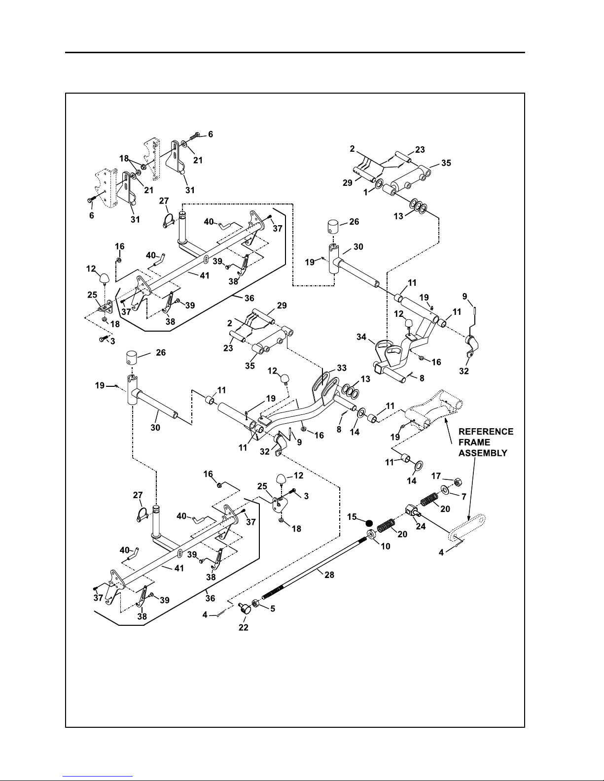
Parts-40
JACOBSEN G PLEX III Series: DN & DP
MAINTENANCE AND PARTS MANUAL
20 LIFT ASSEMBLY - FRONT CUTTING HEADS

Parts-41
* Not Illustrated
LIST OF PARTS
ITEM RANSOMES DESCRIPTION QTY REMARKS
PART NO
JACOBSEN G PLEX III Series: DN & DP
MAINTENANCE AND PARTS MANUAL
20 LIFT ASSEMBLY - FRONT CUTTING HEADS
1 452000562 Washer, 3/4" ID 11/2" OD 1
2 454000297 Pin, cotter 1/8" x 11/8" 12
3 456110341 Screw, 5/16-18 x 7/8" 4
4 451225 Pin, cotter, 4
5 450020265 Nut, jam, 3/8-24 2
6 451111855 Screw, 5/16-18 x 11/4" 3
7 452000326 Washer, 3/8" 2
8 454000572 Pin,cotter,3/16"x13/4" 2
9 64061-26 Pin, spirol, 1/4" 2
10 MBF0654A CoIler, set, 3/8" 2
11 590002786 Bushing 8
12 523126 Bumper, rubber 4
13 548168 Washer,5/8" ID 1 1/4"OD 10
* J303629 Washer 0.766" x 1.312" AR
14 548173 Washer,1" ID 1 3/4"OD 4
15 A129037 Screw, 1/4-20 x 1/4" 2
16 A139301 Nut, flange lock, 5/16-18 6
17 A139910 Nut, crownlock, 3/8-24 2
18 A139322 Nut, ,5/16-18 Staytite 2
* A139301 Nut, flange lock, 5/16-18 4
19 842000044 Fitting, lubrication, 1/4-28 4
* A299316 Fitting, M6 x 90 Deg. 2
20 814499 Spring, compression 4
21 450390 Washer, M8 3
22 839181 Pin, rodconnecting,threaded 2
23 840507 Pin, lift cylinder pivot 2
24 841203 Pin, rod connecting 2
25 841466.06 Bracket, bumper-front 2
26 4126779 Cap, pivotshaft 2
27 841744 Pin, lynch, 3/8"x2" 2
28 842471 Rod, Threaded, 3/8 - 24 2
29 843821 Pin,cylinder pivot 2
30 892175 Pivot, fronthead steering 2
31 892794 Bracket, bumper 2
32 893787 Arm 2
33 893857.07 Arm, LH front 1
34 893858.07 Arm, RH front 1
35 894083.07 Cylinder, hydraulic lift 2
* A230117 Kit, service As Reqd Garner (Uk Spec)
36 897174 Frame assembly, head 2
37 800864 Screw, hex socket head 4 #10-24 x 1/2"
38 842401 Latch 4
39 842402 Rivet 4
40 842403 Handle 4
41 893739.06 Frame 2
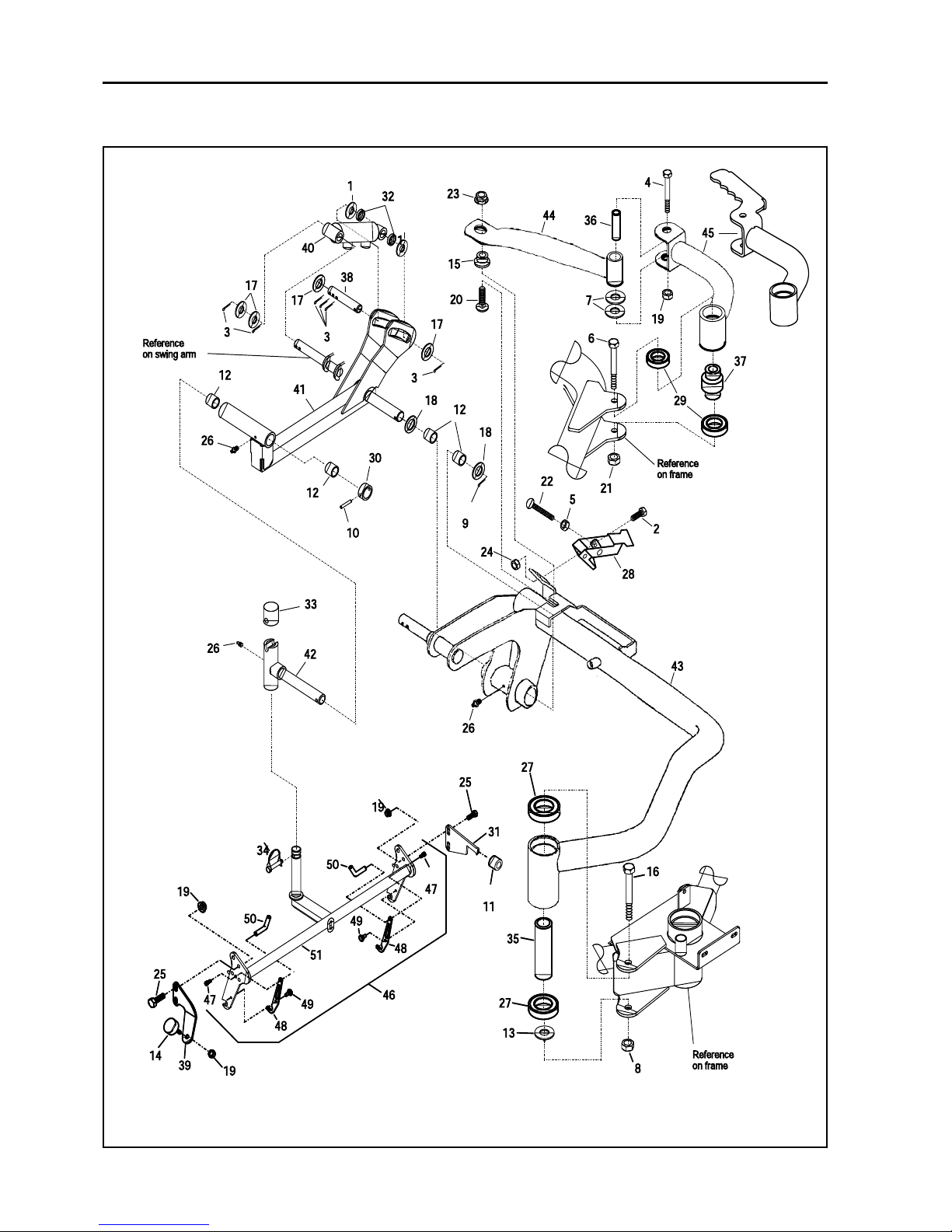
Parts-42
JACOBSEN G PLEX III Series: DN & DP
MAINTENANCE AND PARTS MANUAL
21 LIFT ASSEMBLY - REAR CUTTING HEAD

Parts-43
* Not Illustrated
LIST OF PARTS
ITEM RANSOMES DESCRIPTION QTY REMARKS
PART NO
JACOBSEN G PLEX III Series: DN & DP
MAINTENANCE AND PARTS MANUAL
21 LIFT ASSEMBLY - REAR CUTTING HEAD
1 452000562 Washer, 3/4" ID 11/2" OD 2
2 456110498 Screw, 1/4-20 x 1/2" 2
3 454000297 Pin, cotter, 1/8" x 11/8" 6
4 451030269 Screw, 5/16-24 x 2 1/2" 1
* A139311 Nut-Hex 5/16-24 Whiz 1
5 450120021 Nut, 5/16-18 1
6 456110375 Screw, 3/8-16 x 2 3/4" 1
7 452101285 Washer,1/2" ID 1"OD 2
8 450327 Nut, M16 1
9 454000572 Pin, cotter, 3/16" x 1 3/4" 1
10 64061-26 Pin,spirol,1/4" x 1 3/4" 1
11 517163 Spacer, rubber 1
12 590002786 Bushing 4
13 522840 Washer, thrust 1 To be positioned on top of item 43
14 523126 Bumper, rubber 1
15 524215 Bushing,turf guard 1
16 450082 Screw, M16 x 140 1
17 548168 Washer,5/8" ID 1 1/4" OD 5
18 548173 Washer, 1" ID 13/4" OD 2
19 A139301 Nut, flangelock, 5/16-18 6
20 800071 Bolt, carriage, 3/8 UNC x 1" 1
21 450120267 Nut, centerlock 3/8-16 1
22 800352 Bolt, carriage, 5/16-18 x 3" 1
23 A139910 Nut-Hex 3/8-24 Nyloc 1
24 A139912 Nut, crownlock, 1/4-20 2
25 456110189 Screw, 5/16-18 x 3/4" 4
26 842000044 Fitting, lubrication, 1/4-28 3
27 832499 Bearing, ball, 1" ID 2" OD 2
28 838476 Latch, draw 1
29 839063 Bearing, ball, 5/8" ID 1 3/8" OD 2
30 839410 Bushing, spring stop 1
31 840085.06 Stop, reel 1
32 840344 Bushing 2
33 4126779 Cap 1
34 841744 Pin,lynch, 3/8 x 2" 1
35 843181 Spacer, bearing 1
36 843185 Bushing, pivot 1
37 843195 Spacer, bearing 1
38 843821 Pin,cylinderpivot 1
39 869118.06 Mount, rear frame stop 1
40 893495 Cylinder, hydraulic 1
* A230118 -Kit, service As Reqd Garner (Uk Spec)
41 893856.06 Arm, rear 1
42 893859 Pivot, rear head 1
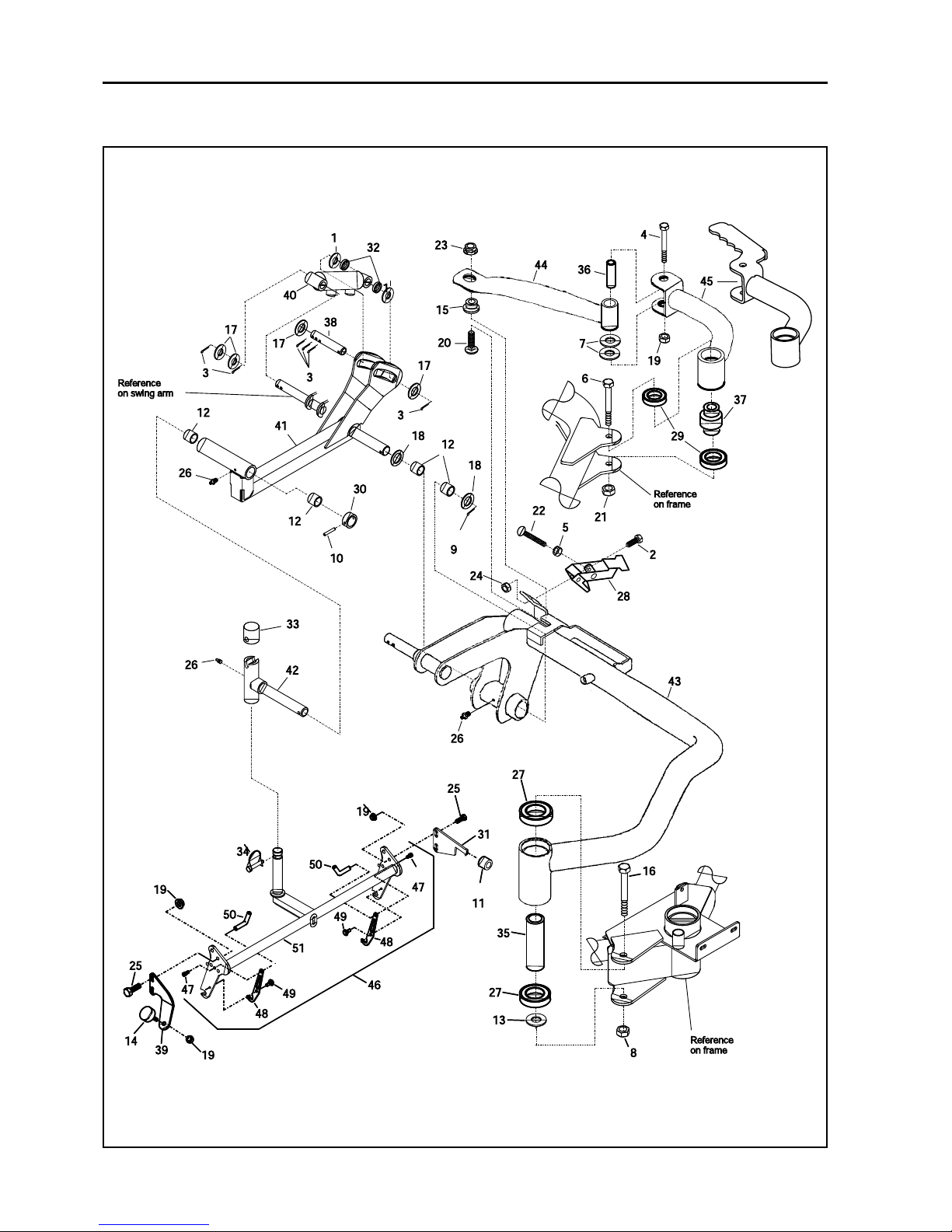
Parts-44
JACOBSEN G PLEX III Series: DN & DP
MAINTENANCE AND PARTS MANUAL
21 LIFT ASSEMBLY - REAR CUTTING HEAD

Parts-45
* Not Illustrated
LIST OF PARTS
ITEM RANSOMES DESCRIPTION QTY REMARKS
PART NO
JACOBSEN G PLEX III Series: DN & DP
MAINTENANCE AND PARTS MANUAL
43 894140.06 Arm, Swing 1
43 4141108 Arm Swing minus handle 1
44 894141.06 Link, arm 1
45 894164.06 Arm, Pivot 1
45 4140646 Arm, pivot c/w handle 1
46 897174 Frame assembly, head 1
47 800864 Screw, hex socket head 2 #10-24 x 1/2"
48 842401 Latch 2
49 842402 Rivet 2
50 842403 Handle 2
51 893739.06 Frame, head steering 1
21 LIFT ASSEMBLY - REAR CUTTING HEAD
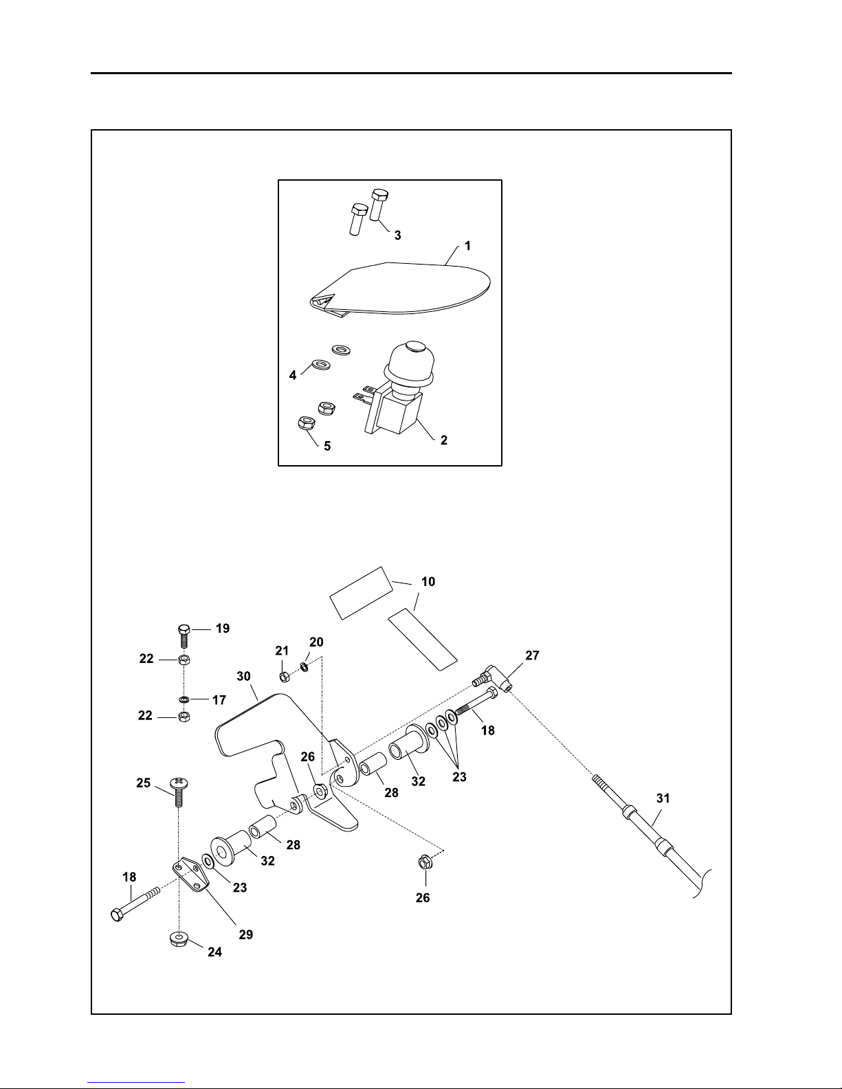
Parts-46
JACOBSEN G PLEX III Series: DN & DP
MAINTENANCE AND PARTS MANUAL
22 MOW / RAISE SWITCH AND SPEED CONTROL PEDAL

Parts-47
* Not Illustrated
LIST OF PARTS
ITEM RANSOMES DESCRIPTION QTY REMARKS
PART NO
JACOBSEN G PLEX III Series: DN & DP
MAINTENANCE AND PARTS MANUAL
22 MOW / RAISE SWITCH AND SPEED CONTROL PEDAL
1 MBE3313C.07 Pad Assy 1
* MBG4897 Anti-slip Switch Cover 1 used item 1
2 2208099 Switch 1
3 450526 Screw Pan-Hd M5 x 12 2
4 450388 Washer M5 2
5 450376 Nut - M5 Nyloc 2
10 840003 Tread, control pedal 1
17 452200134 Lockwasher, 3/8" 3
18 456110024 Screw, 1/4-20 x 1" 2
19 451110134 Screw, 3/8-16 x 11/2" 1
20 452200029 Lockwasher, 1/4" 2
21 450020037 Nut, 1/4-28 2
22 450120039 Nut, 3/8-16 4
23 450392 Washer 4
24 A139908 Nut, flangelock, 1/4-28 2
25 456040021 Screw, 1/4-28 x 1/2", P.T.H 2
26 A139912 Nut, nyloc, 1/4-20 2
27 831518 Ball Joint 2
28 MBG6994 Bushing 2
29 839388 Bracket, pivot mounting 1
30 4115061 Pedal, direction control 1
31 842999 Cable, direction control 1
32 J366877 Nylon Bush 2
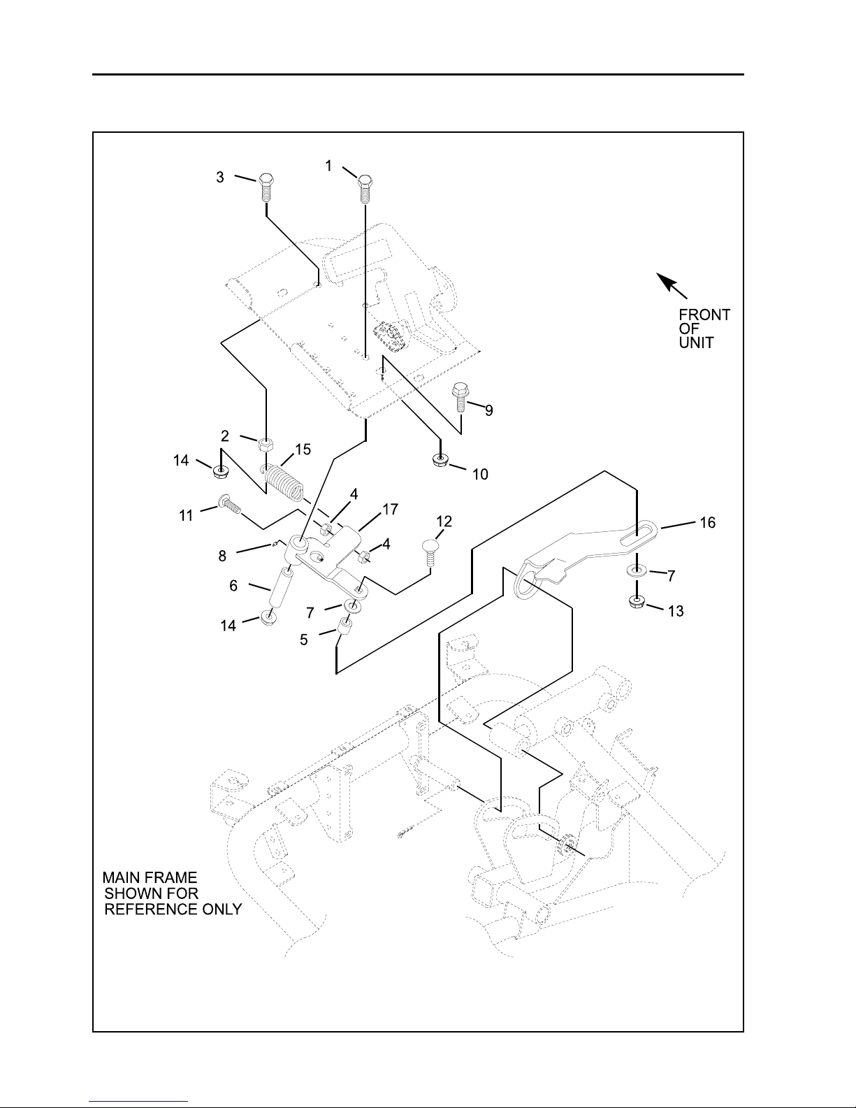
Parts-48
JACOBSEN G PLEX III Series: DN & DP
MAINTENANCE AND PARTS MANUAL
23 MOW SPEED CONTROL

Parts-49
* Not Illustrated
LIST OF PARTS
ITEM RANSOMES DESCRIPTION QTY REMARKS
PART NO
JACOBSEN G PLEX III Series: DN & DP
MAINTENANCE AND PARTS MANUAL
23 MOW SPEED CONTROL
1 A109001 Screw, 3/8-16 x 2 1
2 450120039 Nut, 3/8-16 1
3 456110448 Screw, 3/8-16 x 11/4" 1
4 450324 Nut 2
5 515268 Bushing 1
6 523221 Spacer 1
7 548159 Washer, 5/16 x1 1/4 2
8 A299306 Fitting, lube 1
9 A119003 Screw, flangelock 5/16-18 x 3/4 1
10 A139301 Nut, 5/16-18 flangelock 1
11 452567 Bolt, carriage 1
12 452564 Bolt, carriage 1
13 450378 Nut, crownlock 1
14 450120267 Nut, crownlock 2
15 829500 Spring, extension 1
16 841487 Angle, lockout link 1
17 893359.06 Bellcrank, lockout assembly 1
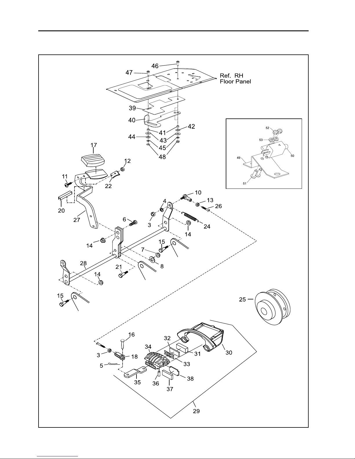
Parts-50
JACOBSEN G PLEX III Series: DN & DP
MAINTENANCE AND PARTS MANUAL
24 BRAKE PEDAL

Parts-51
* Not Illustrated
LIST OF PARTS
ITEM RANSOMES DESCRIPTION QTY REMARKS
PART NO
JACOBSEN G PLEX III Series: DN & DP
MAINTENANCE AND PARTS MANUAL
24 BRAKE PEDAL
1 450390 Washer M8, 1
3 450020053 Nut, 5/16-24 4
4 450411 Lockwasher, M8" 2
5 451255 Pin, cotter, 2
6 451110134 Screw, 2
7 450120398 3/8 UNC Thin Nyloc. 1 Used Item 21.
8 452000326 Washer, 3/8" 1
9 452101285 Washer, 1/2" 1
10 523253 End 2
11 800177 Screw, 5/16-18 x 3/4" Trus Hd. 3
12 A139322 Nut, crownlock flange, 5/16-18 3
13 450020249 Nut, left hand thread 5/16-24 2
14 450120267 Nut, crownlock flange, 3/8-16 4
15 800812 Bolt, shoulder, 3/8-16 x 1" 2
16 806703 Pin, clevis, 5/16 x 1" 2
17 4125972 Cover, footpedal 1
18 810722 Yoke 2
19 823332 Bushing 1
20 829726 Trim, push on, 12' AR
21 A129100 Screw 3/8-16x1" Shoulder 1
22 840420 Plate, latch 1
23 MBG5293 PawI, lock 1
24 842598 Spring, extension 1
25 843160 Hub,wheel&disc 2
26 843252 Rod,threaded 5/16-24 2
27 4126019 Pedal, brake 1
28 894166 .06 Shaft,brakearm 1
29 2188147 Brake, complete, LEFT 1
2188148 Brake, complete, RIGHT 1
30 2188147-01 Bracket 1
31 2188147-02 Brake pad-cam 1
32 2188147-03 Pad-support 1
33 2188147-04 Spring-lever retainer 1
34 2188147-05 Housing 1
35 2188147-06 Cam, LEFT 1
2188148-01 Cam, RIGHT 1
36 2188147-07 Pin, pivot 1
37 2188147-08 Brake pad-carrier side 1
38 2188147-09 Pad-support 1
39 4118010 Wear Plate 1
40 4116522 Pawl Latch 1
41 823332 Spacer 2
42 111840 Wavey Washer, 1/2" 1
43 452101285 Washer, 1/2" 2
44 4119002 Crinkle Washer, M12 1
45 450390 Washer, M8 2
46 800177 Screw, 5/16-18 x 3/4" 1
47 4119281 Screw 5/16-18 x 3/4" 1
48 001393222 Flange Nut,, 5/16-18" 2
49 MBG6914 Bracket Interlock switch 1 Brake switch Bracket
50 W038383 Switch 1
51 450528 Screw M5 x 16 2
52 450376 Nut M5 Nyloc 2
53 450388 Washer M5 2
* 009057770 Brake Switch Lead 1

Parts-52
JACOBSEN G PLEX III Series: DN & DP
MAINTENANCE AND PARTS MANUAL
25 SEAT

Parts-53
* Not Illustrated
LIST OF PARTS
ITEM RANSOMES DESCRIPTION QTY REMARKS
PART NO
JACOBSEN G PLEX III Series: DN & DP
MAINTENANCE AND PARTS MANUAL
25 SEAT
1 4133662 Seat 1
2 306932 Nut, 5/16-18 2
3 523224 Bumper, rubber 2
4 523356 Adjuster, seat wihandle (left) 1
5 523357 Adjuster seat (right) 1
6 A119003 Screw, flanglok, 5/16-18 x 3/4" 4
7 A139322 Nut, crowniock flange, 5/16-18 6
8 456110359 Screw, flange, 5/16-18 x 1" 2
9 823332 Bushing 2
10 833851 Seal 1
11 842933 .06 Panel,seatbase 1
12 2196054 Arm Rest Set (accessory) 1
13 198059 Arm Rest (left) 1
14 198066 Arm Rest (right) 1
15 548604 Screw, flnglck, 5/16-18 x 3/4" 6

Parts-54
JACOBSEN G PLEX III Series: DN & DP
MAINTENANCE AND PARTS MANUAL
26 DECALS

Parts-55
* Not Illustrated
LIST OF PARTS
ITEM RANSOMES DESCRIPTION QTY REMARKS
PART NO
JACOBSEN G PLEX III Series: DN & DP
MAINTENANCE AND PARTS MANUAL
26 DECALS
1 A903488 Decal - Fan 1
2 009114340 Decal - Diesel 1
3 4124007 Decal - Jacobsen 2
4 840065 Decal - Speed Ctrl 1
6 A911410 Decal - Battery 1
7 4124190 Decal - G-plex III 1
8 A903493 Decal - Hyd Press Leak 1
9 A903489 Decal - Bystander 1
10 A903491 Decal - Instruction 1
11 A903492 Decal - Hot 1
13 838363 Decal - Throttle 1
14 838367 Decal - Parking Brake P 1
15 840748 Decal - Remove Ignition Key 1
16 4123912 Decal - G-Plex III with Swoosh 1
17 009039640 Decal - Choke 1
18 A903477 Decal - Noise 105 1
19 A903950 Label - Tyre Pressure 3
20 A911416 Decal - Slope 15 Deg 1
21 A911430 Decal - Jacking Point 3
22 4124005 Decal - Jacobsen 1 Steering Wheel Centre
23 4124182 Decal - Jacobsen 1 Steering Column
24 A911546 Decal - Textron 2
25 A293952 Decal - Paddle Control 1
26 A923953 Decal - Footswitch. 1
27 A911424 Decal - Lead Free Gasoline 1
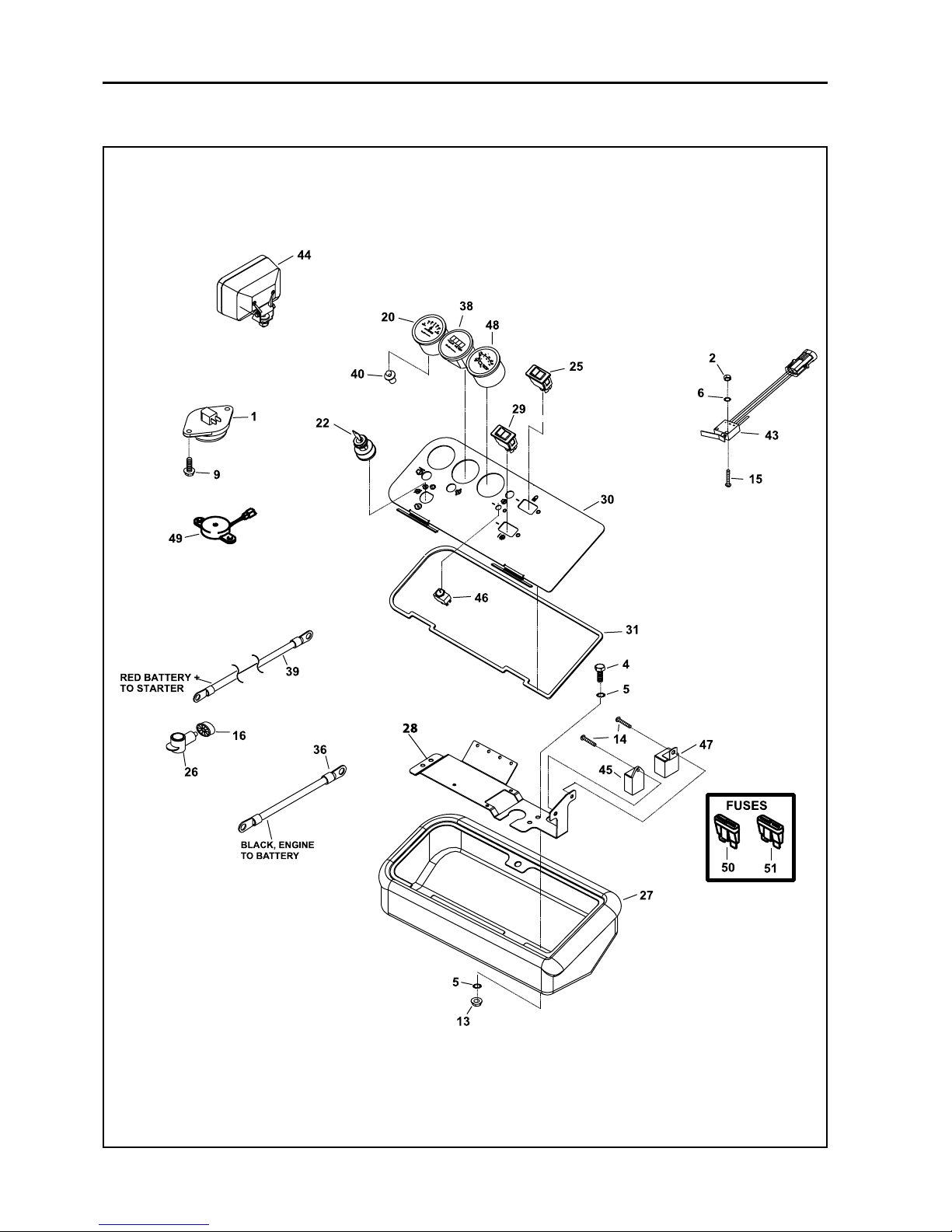
Parts-56
JACOBSEN G PLEX III Series: DN & DP
MAINTENANCE AND PARTS MANUAL
27 CONTROL PANEL AND ELECTRICAL COMPONENTS DIESEL

Parts-57
* Not Illustrated
LIST OF PARTS
ITEM RANSOMES DESCRIPTION QTY REMARKS
PART NO
JACOBSEN G PLEX III Series: DN & DP
MAINTENANCE AND PARTS MANUAL
1 W158135-01 Switch, seat 1
2 A182003 Nut, M3 2
4 456110359 Screw, 5/16-18 x 1" 4
5 A159410 Lockwasher, 5/16" 8
9 548045 Screw, 1/4-20 x 3/4" 2
13 A139301 Nut, flange lock 5/16-18 4
15 A800955 Screw, #6-32 x 3/4" 2
16 A825917 Grommet 2
20 A828913 Gauge, Volt 1
22 A828912 Switch, ignition 1
25 A829546 Main-Dip Beam Switch 1 BRITAX 511-024
* A829566 Lens Insert 1 USED ITEM 25/29
26 A841895 Cover, Battery Terminal 1
27 A843612.07 Housing, instrument 1
28 4123645 Bracket, instrument 1
29 A829599 Reel Enable 1
30 4124217 Panel, instrument (DIESEL) 1
31 A844294 Gasket, instrument panel 1
36 4124765 Wire, black ground engine 1
38 A810966 Gauge, hour meter 1
39 A905037 Wire, red, battery to starter 1
40 A823270 Bulb 1
42* 4124360 Harness, main wire 1
42A 4124361 Harness, Paddle Switch 1
43 A894521 Switch, NO lever 1
44 A823264 Headlight 2
45 A824985 Timer, lamp 12VDC 1
46 A828926 Switch, Pre-Heat 1
47 A840002-1 Timer, Fuel shut off 1
48 A828911 Gauge, water temperature 1
49 A824999 Buzzer 1
50 A826000 Fuse, 20 amp 4
51 A833038 Fuse, 30 amp 1
52* A907933 Adj. Grip Latch (Southco) 2
53* MBG5090A Pod Support 2
27 CONTROL PANEL AND ELECTRICAL COMPONENTS DIESEL
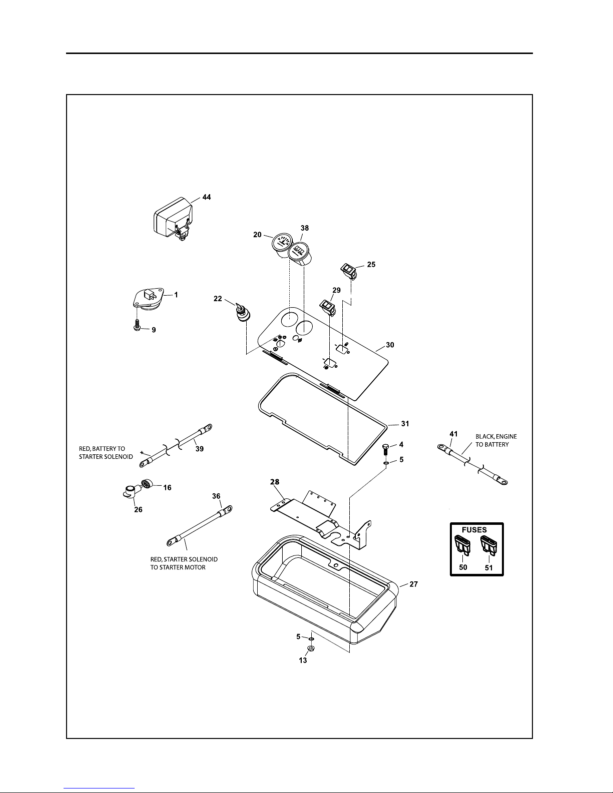
Parts-58
JACOBSEN G PLEX III Series: DN & DP
MAINTENANCE AND PARTS MANUAL
28 CONTROL PANEL AND ELECTRICAL COMPONENTS GASOLINE

Parts-59
* Not Illustrated
LIST OF PARTS
ITEM RANSOMES DESCRIPTION QTY REMARKS
PART NO
JACOBSEN G PLEX III Series: DN & DP
MAINTENANCE AND PARTS MANUAL
28 CONTROL PANEL AND ELECTRICAL COMPONENTS GASOLINE
1 W158135-01 Switch, seat 1
4 456110359 Screw, 5/16-18 x 1" 4
5 A159410 Lockwasher, 5/16" 8
9 548045 Screw, 1/4-20 x 3/4" 2
13 A139301 Nut, flange lock 5/16-18 4
16 825917 Grommet 2
20 A828913 Gauge, Volt 1
22 A828912 Switch, ignition 1
25 A829546 Main-Dip Beam Switch 1 BRITAX 511-024
* A829566 Lens Insert 1 USED ITEM 25/29
26 841895 Cover, Battery Terminal 1
27 843612.07 Housing, instrument 1
28 4123645 Bracket, instrument 1
29 A829599 Reel Enable 1
30 4123940 Panel, instrument (GASOLINE) 1
31 844294 Gasket, instrument panel 1
36 4124159 Wire, black ground chassis 1
38 A810966 Gauge, hour meter 1
39 4124157 Wire, red, battery to starter 1
41 4124765 Wire, black ground engine 1
42* 4123903 Harness, Complete 1
42.1* 4123904 Harness, 1
42.2* 4123905` Harness, 1
44 A823264 Headlight 2
50 826000 Fuse, 20 amp 4
51 833038 Fuse, 30 amp 1
52* A907933 Adj. Grip Latch (Southco) 2
53* MBG5090A Pod Support 2
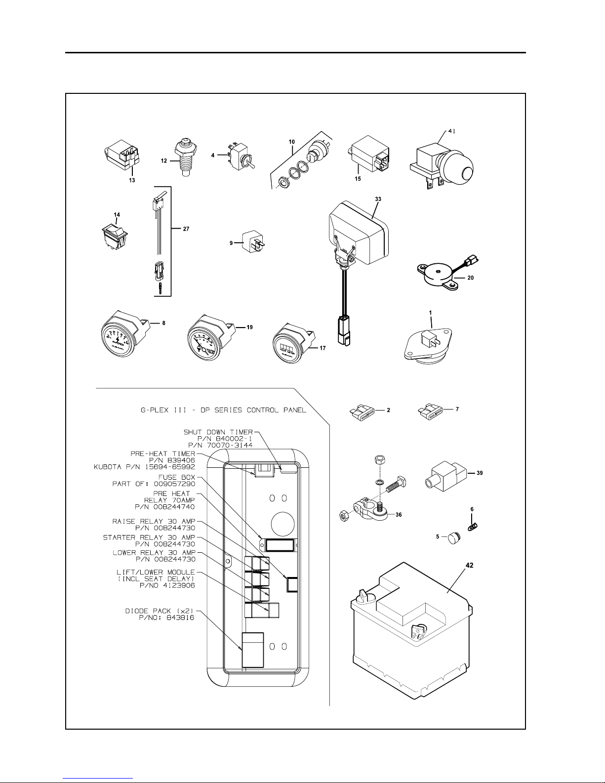
Parts-60
JACOBSEN G PLEX III Series: DN & DP
MAINTENANCE AND PARTS MANUAL
29 ELECTRICAL COMPONENTS DIESEL
 Loading...