


Technical Manual
Teknik Kılavuz
When Performance Matters.
™
UYARI
Yanlı kullanılması durumunda bu makine ciddi yaralanmaya neden olabilir.
Bu makineyi kullanan ve bakımını yapan ki i, do ru kullanımı için e itilmeli,
tehlikeleri konusunda uyarılmalı ve makineyi kurmadan, çalı tırmadan,
ayarlamadan veya bakım yapmadan önce tüm kılavuzu okumalıdır.
WARNING
If incorrectly used, this machine can cause severe injury. Those who use
and maintain this machine should be trained in its proper use, warned of its
dangers and should read the entire manual before attempting to set up,
operate, adjust or service the machine
Eclipse
®
4170162-TR-rev.G
InCommand
63300 – Eclipse 118, 18” 11 Blade Reel, Gen-Set
63313 – Eclipse 118, 18” 11 Blade Reel, Battery Pack
63327 – Eclipse 118, 18” 15 Blade Reel, Gen-Set
63331 – Eclipse 118, 18” 15 Blade Reel, Battery Pack
63301 – Eclipse 118F, Floating 18” 11 Blade Reel, Gen-Set
63314 – Eclipse 118F, Floating 18” 11 Blade Reel, Battery Pack
63328 – Eclipse 118F, Floating 18” 15 Blade Reel, Gen-Set
63332 – Eclipse 118F, Floating 18” 15 Blade Reel, Battery Pack
63302 – Eclipse 122, 22” 11 Blade Reel, Gen-Set
63311 – Eclipse 122, 22” 11 Blade Reel, Battery Pack
63325 – Eclipse 122, 22” 15 Blade Reel, Gen-Set
63329 – Eclipse 122, 22” 15 Blade Reel, Battery Pack
63303 – Eclipse 122F, Floating 22” 11 Blade Reel, Gen-Set
63312 – Eclipse 122F, Floating 22” 11 Blade Reel, Battery Pack
63326 – Eclipse 122F, Floating 22” 15 Blade Reel, Gen-Set
63330 – Eclipse 122F, Floating 22” 15 Blade Reel, Battery Pack
63304 – Eclipse 126, 26” 7 Blade Reel, Gen-Set
63315 – Eclipse 126, 26” 7 Blade Reel, Battery Pack
™
63300 – Eclipse 118, 457 mm 11 Silindir Bıçaklı, Jeneratör Seti
63313 – Eclipse 118, 457 mm 11 Silindir Bıçaklı, Pil Paketi
63327 – Eclipse 118, 457 mm 15 Silindir Bıçaklı, Jeneratör Seti
63331 – Eclipse 118, 457 mm 15 Silindir Bıçaklı, Pil Paketi
63301 – Eclipse 118F, Hareketli 457 mm 11 Silindir Bıçaklı, Jeneratör Seti
63314 – Eclipse 118F, Hareketli 457 mm 11 Silindir Bıçaklı, Pil Paketi
63328 – Eclipse 118F, Hareketli 457 mm 15 Silindir Bıçaklı, Jeneratör Seti
63332 – Eclipse 118F, Hareketli 457 mm 15 Silindir Bıçaklı, Pil Paketi
63302 – Eclipse 122, 559 mm 11 Silindir Bıçaklı, Jeneratör Seti
63311 – Eclipse 122, 559 mm 11 Silindir Bıçaklı, Pil Paketi
63325 – Eclipse 122, 559 mm 15 Silindir Bıçaklı, Jeneratör Seti
63329 – Eclipse 122, 559 mm 15 Silindir Bıçaklı, Pil Paketi
63303 – Eclipse 122F, Hareketli 559 mm 11 Silindir Bıçaklı, Jeneratör Seti
63312 – Eclipse 122F, Hareketli 559 mm 11 Silindir Bıçaklı, Pil Paketi
63326 – Eclipse 122F, Hareketli 559 mm 15 Silindir Bıçaklı, Jeneratör Seti
63330 – Eclipse 122F, Hareketli 559 mm 15 Silindir Bıçaklı, Pil Paketi
63304 – Eclipse 126, 660 mm 7 Silindir Bıçaklı, Jeneratör Seti
63315 – Eclipse 126, 660 mm 7 Silindir Bıçaklı, Pil Paketi
GB
United
Kingdom
TR
Turkey

11524 WILMAR BLVD,
CHARLOTTE, NC 28273
®
kg kW
1-800-848-1636 (US)
PRODUCT OF U.S.A.
A Textron Company
FOREWORD
This manual contains safety, operating, adjustment,
maintenance, troubleshooting instructions and parts list
for your new Jacobsen machine . This manual should be
stored with the equipment for reference during operation.
Before you operate your machine, you and each operator
you employ should read the manual carefully in its
entirety. By following the safety, operating and
maintenance instru ctions , you will prolo ng the li fe of yo ur
equipment and maintain its maximum efficiency.
If additional information is needed, contact your
Jacobsen Dealer.
The serial plate is located on the rear crossbar of the
frame. Jacobs en re comm ends you re cord these nu mbe rs
below for easy reference.
Suggested Stocking Guide
To Keep your Equipment fully operational and productive, Jacobsen suggests you maintain a stock of the more
commonly used maintenance items. We have included part numbers for additional support materials and training aids.
To order any of the following material:
1. Write your full name and complete address on your
order form.
2. Explain where and how to make shipment:
3. Order by the quantity desired, the part number, and
the description of the part.
4. Send or bring the order to your authorized Jacobsen
Dealer.
❑ UPS ❑ Regular Mail
❑ Overnig ht ❑ 2nd Day
Service Parts
Qty. Part No. Description Qty. Part No. Description
4102780 50 Amp Fuse 2811106 Motor to Pulley Belt
4169341 25 Amp CIrcuit Breaker 2811070 Pulley to Traction Drum Belt
4131618 Ignition Key
Service Support Material
Qty. Part No. Description
4170162 Technical Manual
4166960 Operator Training Video
Qty. Description
Service Manual
2006/42/EC
These are the Original instructions verified by Jacobsen
A Textron Company.
© Copyright 2011, Jacobsen, A Textron Company. “All rights
reserved, inclu ding the right to r epr od uce this material or portion s
en-2
thereof in any form.”
Proposition 65 Warning
This product contains or emits
chemicals known to State of California
to cause cancer and birth defects or
other reproductive harm.
LITHO IN U.S.A. 4-2011

Table of Contents
1SAFETY
1.1 Operating Safety . . . . . . . . . . . . . . . . . . . . . . 4
1.2 Important Safety Notes . . . . . . . . . . . . . . . . . 5
2 SPECIFICATIONS
2.1 Product Identification . . . . . . . . . . . . . . . . . . 6
2.2 Mower . . . . . . . . . . . . . . . . . . . . . . . . . . . . . . 7
2.3 Traction and Differential . . . . . . . . . . . . . . . . 7
2.4 Weights . . . . . . . . . . . . . . . . . . . . . . . . . . . . . 7
2.5 Gen-Set Power Module . . . . . . . . . . . . . . . . 7
2.6 Battery Power Module . . . . . . . . . . . . . . . . . 8
2.7 Accessories & Support Literature . . . . . . . . . 9
2.8 Declaration of Conformity . . . . . . . . . . . . . . 10
3DECALS
3.1 Decals . . . . . . . . . . . . . . . . . . . . . . . . . . . . . 13
4 CONTROLS
4.1 Icons . . . . . . . . . . . . . . . . . . . . . . . . . . . . . . 16
4.2 Handle Controls . . . . . . . . . . . . . . . . . . . . . 16
4.3 LCD Display . . . . . . . . . . . . . . . . . . . . . . . . 17
4.4 Frequency of Cut . . . . . . . . . . . . . . . . . . . . 20
4.5 Gas Power Module Controls . . . . . . . . . . . . 24
4.6 Battery Power Module Controls . . . . . . . . . 24
5 OPERATION
5.1 Daily Inspection . . . . . . . . . . . . . . . . . . . . . 25
5.2 Interlock System (O.P.C.) . . . . . . . . . . . . . . 25
5.3 Operating Procedures . . . . . . . . . . . . . . . . . 26
5.4 Starting/Stopping . . . . . . . . . . . . . . . . . . . . 27
5.5 Mowing . . . . . . . . . . . . . . . . . . . . . . . . . . . . 28
5.6 Transport Wheels (Optional) . . . . . . . . . . . . 29
5.7 Grass Catcher . . . . . . . . . . . . . . . . . . . . . . . 29
5.8 Daily Maintenance . . . . . . . . . . . . . . . . . . . 30
6 ADJUSTMENTS (ALL UNITS)
6.1 General . . . . . . . . . . . . . . . . . . . . . . . . . . . . 31
6.2 Brake . . . . . . . . . . . . . . . . . . . . . . . . . . . . . 31
6.3 Speed Paddle Stops . . . . . . . . . . . . . . . . . . 31
6.4 Handle . . . . . . . . . . . . . . . . . . . . . . . . . . . . 32
6.5 Traction Belts . . . . . . . . . . . . . . . . . . . . . . . 32
6.6 Front Roller Weight . . . . . . . . . . . . . . . . . . . 33
6.7 Torque Specification . . . . . . . . . . . . . . . . . . 34
8 FLOATING HEAD REEL ADJUSTMENTS
8.1 General . . . . . . . . . . . . . . . . . . . . . . . . . . . .37
8.2 Bedknife-To-Reel . . . . . . . . . . . . . . . . . . . . .37
8.3 Bedknife Adjustment . . . . . . . . . . . . . . . . . .38
8.4 Cutting Height . . . . . . . . . . . . . . . . . . . . . . .39
8.5 Reel Bearing . . . . . . . . . . . . . . . . . . . . . . . .39
8.6 Reel Assembly Removal . . . . . . . . . . . . . . .39
9 BATTERY POWER MODULE
9.1 Safety . . . . . . . . . . . . . . . . . . . . . . . . . . . . .40
9.2 General . . . . . . . . . . . . . . . . . . . . . . . . . . . .40
9.3 Maintenance . . . . . . . . . . . . . . . . . . . . . . . .41
9.4 Cleaning Batteries . . . . . . . . . . . . . . . . . . . .41
9.5 Battery Charger . . . . . . . . . . . . . . . . . . . . . .42
9.6 Battery Installation . . . . . . . . . . . . . . . . . . . .43
9.7 Replacing Battery Pack . . . . . . . . . . . . . . . .44
10 GEN-SET POWER MODULE
10.1 Engine . . . . . . . . . . . . . . . . . . . . . . . . . . . . .45
10.2 Engine Oil . . . . . . . . . . . . . . . . . . . . . . . . . .45
10.3 Engine Speed . . . . . . . . . . . . . . . . . . . . . . .46
10.4 Fuel . . . . . . . . . . . . . . . . . . . . . . . . . . . . . . .46
11 MAINTENANCE
11.1 General . . . . . . . . . . . . . . . . . . . . . . . . . . . .47
11.2 Tires (Option) . . . . . . . . . . . . . . . . . . . . . . . .47
11.3 Wheel Bearing . . . . . . . . . . . . . . . . . . . . . . .47
11.4 Backlapping and Grinding . . . . . . . . . . . . . .48
11.5 Storage . . . . . . . . . . . . . . . . . . . . . . . . . . . .49
12 TROUBLESHOOTING
12.1 General . . . . . . . . . . . . . . . . . . . . . . . . . . . .50
13 MAINTENANCE & LUBRICATION CHARTS
13.1 General . . . . . . . . . . . . . . . . . . . . . . . . . . . .51
13.2 Maintenance Chart . . . . . . . . . . . . . . . . . . .51
13.3 Lubrication Chart . . . . . . . . . . . . . . . . . . . . 52
14 PARTS CATALOG
14.1 How To Use The Parts Catalog . . . . . . . . . .53
14.2 To Order Parts . . . . . . . . . . . . . . . . . . . . . . .53
14.3 Parts Catalog Table of Contents . . . . . . . . .53
7 FIXED HEAD REEL ADJUSTMENTS
7.1 General . . . . . . . . . . . . . . . . . . . . . . . . . . . . 35
7.2 Reel To Bedknife . . . . . . . . . . . . . . . . . . . . 35
7.3 Bedknife Adjustment . . . . . . . . . . . . . . . . . . 36
7.4 Cutting Height . . . . . . . . . . . . . . . . . . . . . . . 36
> Change from previous revision
en-3

1 SAFETY
!
1 SAFETY
1.1 OPERATING SAFE TY _____________________ __ ___ __ __ ________________________
WARNING
EQUIPMENT OPERATED IMPROPERLY OR BY UNTRAINED PERSONNEL CAN BE DANGEROUS.
Familiarize yourself with the location and proper use of all controls. Inexperienced operator’s should receive
instruction from someone familiar with the equipment before being allowed to operate the machine.
1. Safety is dependent upon the awareness, concern
and prudence of those who operate or service the
equipment. Never allow minors to operate any
equipment.
2. It is your responsibility to read this manual and all
publications assoc iated with this equipment (Engine
Manual, Battery Charger Manual, accessories, and
attachments). If the operator cannot read English it
is the owner’s responsibility to explain the material
contained in this manual to them.
3. Learn the proper use of the machine, the location
and purpose of all the controls before you operate
the equipment. Working with unfamiliar equipment
can lead to accidents.
4. Never allow anyone to operate or service the
machine or its attachments without proper training
and instructions; or while under the influence of
alcohol or drugs.
5. Wear all the necessary protective clothing and
personal safety devi ces to protect your head, eyes,
ears, hands, and feet. Long hair, loose clothing, or
jewelry may get tangled in moving parts. Operate
the machine only in daylight or in good artificial light.
6. Evaluate the terrain to determine what accessories
and attachments are neede d to properly and safely
perform the job. Only use accessories and
attachments approved by Jacobsen.
7. Stay alert for holes in the terrain and other hidden
hazards.
8. Inspect the area where the eq uipment will be used.
Pick up all the debris you can find be fore operating.
Beware of overhead obstructions (low tree limbs,
electrical wires, etc.) and also underground
obstacles (sprinklers, p ipes, tree roots, etc.) Ente r a
new area cautiously. Stay alert for hidden hazards.
9. Do not carry passengers. Ke ep bystanders and pets
a safe distance away.
10. Never direct discharge of material toward
bystanders, nor allow anyone near the machine
while in operation. The owner/operator can prevent
and is responsible for injuries inflicted to
themselves, to bystanders, and damage to property.
11. Never operate equipment that is not in perfect
working order or is without decals, guards, shields,
discharge deflectors, or other protective devices
securely fastened in place.
12. Never disconnect or bypass any switch.
13. Keep the unit clean. Disconnect the power
connector before stor ing. Do not store unit near an
open flame or flammable debris.
14. Place unit on a flat surface, disengage all drives,
and engage parking brake before energizing the
unit.
15. Local regulations may restrict the age of the
operator.
16. Operate the machine across the face of the slope
(horizontally), not up and do wn the slope (v ertically).
Never operate on wet grass.
17. Always operate at speeds that allow you to have
complete control of the machine. Be sure of your
footing, keep a firm hold on the handle, and walk,
never run.
Gen-Set Power Module
18. Carbon monoxide in t he exhaust fumes can be fatal
when inhaled. Never operate the engine without
proper ventilation.
19. Fuel is highly flammable, handle with care. See
Section 4.8 .
20. Before you clean, adjust or repair this equipment,
stop the engine, discon nect the spark plug wi re, and
keep the wire away from the plug to prevent
accidental starting. Disconnect the power connector.
21. Keep the engine clean. Allow the engine to cool,
always close fuel shut off valve, and remove the
spark plug wire from the spark plug before storing.
Do not store unit near an open flame or flammabl e
debris.
Battery Power Module
22. Before you clean, adjust, or repair this equipment,
disconnect the power connector.
23. Do not remove battery pack without unit on
kickstand.
en-4

SAFETY 1
!
!
This machine is to be operated and maintained as specified in this manual and is intended for the pr ofession al
maintenance of specialized turf grasses. It is not intended for use on rough terrain or long grasses.
1.2 IMPORTANT SAFETY NOTES________________________________________________
This safety alert symbol is used to alert you to potential hazards.
DANGER - Indicates an imminently hazardous situation which, if not avoided, WILL result in death or serious injury.
WARNING - Indicates a potentially hazardous situation which, if not avoided, COULD result in dea th or serious
injury.
CAUTION - Indicates a potenti ally haz ardous situa tion whi ch, i f not av oided, MAY result in minor or moderat e inju ry
and property damage. It may also be used to alert against unsafe practices.
NOTICE - Indicates a potentially hazardous situati on which, if no t avoided, MAY result in property damage. It may
also be used to alert against unsafe practices.
For pictorial clar ity, some illustrations in this m anual may sh ow shields, gua rds or plates ope n or removed. U nder no
circumstances should this equipment be operated without these devices securely fastened in place.
WARNING
The Interlock System on this machine will shut off the reel and traction drive if
the operator releases the O.P.C. (Operator Presence Control) bail.
To protect the operator a nd othe rs from in jury, never operate equipment with
the Interlock System disconnected or malfunctioning.
WARNING
1. Before leaving the operator’s position for any reason:
a. Disengage all drives.
b. Engage parking brake.
c. Disconnect power connecto r.
2. Keep hands, feet, and clothing away from moving parts. Wait for all
movement to stop before you clean, adjust, or service the machine.
3. Keep the area of operation clear of all bystanders and pets.
4. Chock or block the wheels if the machine is left on an incline.
5. Never operate mowing equipment without the discharge deflector
securely fastened in place.
By following all instructions in this manual, you will prolong the life of your machine and maintain its maximum
efficiency. Adjustments and maintenance should always be performed by a qualified technician.
If additional informati on or service is needed, co ntact your Authorized Jacobsen Dea ler who is kept informed of th e
latest methods to service this equip ment and can pro vide prompt an d efficient servi ce. Use of other than original or
authorized Jacobsen parts and Accessories will void the warranty.
en-5

2 SPECIFICATIONS
11524 WILMAR BLVD,
CHARLOTTE, NC 28273
®
kg kW
1-800-848-1636 (US)
PRODUCT OF U.S.A.
A Textron Company
92.3 2.6 XXXX
63300001651
2 SPECIFICATIONS
2.1 PRODUCT IDE N TI FIC ATI ON_________________________________________________
63300............................ Eclipse® 118 base unit with 18 in.
(457 mm) 11 blade reel and
InCommand™ control system.
Gen-Set power module.
®
63313............................ Eclipse
(457 mm) 11 blade reel and
InCommand™ control system.
Battery power module.
63327............................ Eclipse
(457 mm) 15 blade reel and
InCommand™ control system.
Gen-Set power module.
63331............................ Eclipse
(457 mm) 15 blade reel and
InCommand™ control system.
Battery power module.
63301............................ Eclipse
floating 18 in. (457 mm) 11 blade
reel and InCommand™ control
system. Gen-Set power module.
63314............................ Eclipse
floating 18 in. (457 mm) 11 blade
reel and InCommand™ control
system. Battery power module.
63328............................ Eclipse
floating 18 in. (457 mm) 15 blade
reel and InCommand™ control
system. Gen-Set power module.
63332............................ Eclipse
floating 18 in. (457 mm) 15 blade
reel and InCommand™ control
system. Battery power module.
63302............................ Eclipse
(559 mm) 11 blade reel and
InCommand™ control system.
Gen-Set power module.
63311 ............................ Eclipse
(559 mm) 11 blade reel and
InCommand™ control system.
Battery power module.
63325............................ Eclipse
(559 mm) 15 blade reel and
InCommand™ control system.
Gen-Set power module.
63329............................ Eclipse
(559 mm) 15 blade reel and
InCommand™ control system.
Battery power module.
63303............................ Eclipse
floating 22 in. (457 mm) 11 blade
en-6
reel and InCommand™ control
system. Gen-Set power module.
118 base unit with 18 in.
®
118 base unit with 18 in.
®
118 base unit with 18 in.
®
118F base unit with
®
118F base unit with
®
118F base unit with
®
118F base unit with
®
122 base unit with 22 in.
®
122 base unit with 22 in.
®
122 base unit with 22 in.
®
122 base unit with 22 in.
®
122F base unit with
®
63312.............................Eclipse
122F base unit with
floating 22 in. (457 mm) 11 blade
reel and InCommand™ control
system. Battery power module.
®
63326.............................Eclipse
122F base unit with
floating 22 in. (457 mm) 15 blade
reel and InCommand™ control
system. Gen-Set power module.
®
63330.............................Eclipse
122F base unit with
floating 22 in. (457 mm) 15 blade
reel and InCommand™ control
system. Battery power module.
®
63304.............................Eclipse
126 base unit with 26 in.
(660 mm) 7 blade reel and
InCommand™ control system.
Gen-Set power module.
®
63315.............................Eclipse
126 base unit with 26 in.
(660 mm) 7 blade reel and
InCommand™ control system.
Battery power module.
Serial Number ...............An identification plate, like the one
shown, listing the serial number, is
attached to the rear crossbar.
2
Product
63300
63301
63302
63303
63304
63311
63312
63313
63314
63315
63325
63326
62237
63328
63329
63330
63331
63332
EEC Sound
Power
93 dBA
94 dBA
88 dBA
88 dBa
93 dBA
83 dBA
83 dBA
84 dBA
85 dBA
86 dBA
95 dBA
95 dBA
86 dBA
86 dBA
86 dBA
86 dBA
86 dBA
86 dBA
Vibratio n M/S
Arms
3.344
3.110
3.877
5.061
4.988
0.822
0.481
0.661
0.901
0.882
2.342
3.055
2.184
3.181
1.004
1.066
1.440
0.661

SPECIFICATIONS 2
2.2 MOWER__________________________________________________________________
Reel..................................7, 9, 11, or 15 blades, hardened
high manganese carbon steel.
Reel Diameter..................5 in. (127 mm)
Cutting Width ...................18, 22 or 26 in. (457, 559 or
660 mm)
Height of cut.....................1/16 to 7/16 in. (1.6 to 11 mm)
Bedknives ........................Hardened carbon steel
High Profile ................5/32” - 7/16” (4 - 11 mm) cut
Low Profile.................1/8” - 7/32” (3.2 - 5.6 mm) cut
Tournament................3/32” - 5/32” (2.4 - 4 mm) cut
Super Tournament.....1/16” - 7/64” (1.6 - 2.8 mm) cut
Frequency of Cut
15 Blade Reel............0.064 - 0.133 in. (1.6 - 3.4 mm)
11 Blade Reel ............0.087 - 0.178 in. (2.2 - 4.5 mm)
9 Blade Reel..............0.106 - 0.217 in. (2.7 - 5.5 mm)
7 Blade Reel..............0.136 - 0.279 in. (3.4 - 7.1 mm)
2.3 TRACTION AND DIFFERENTIA L____________ _____________________ ___ __ __ ______
Transport Tires (Option)...11 x 4 pneumatic bidirectional.
Reel Drive........................Independent direct drive motor.
Traction Drive...................Independent drive motor with two
synchronous polyurethane belts.
Traction Reduction Ratio..15.15:1
Mowing speed..................0 - 3.4 m.p.h. (5.31 km/h)
Differential........................Full automotive type, housed in
traction drum
Rear Drive Drum..............Machined aluminum alloy
2 Section, 7-3/4 (O.D.) x 10-31/32
2.4 WEIGHTS ________________________________________________________________
Gen Set Mowers
Weights: Without Grass Catcher Lbs. (kg)
63300 – Eclipse 118 11 Blade....................... 203 (92.3)
63301 – Eclipse 118F 11 Blade..................... 243 (110.4)
63302 – Eclipse 122 11 Blade....................... 224 (101.6)
63303 – Eclipse 122F 11 Blade .................... 249 (113.0)
63304 – Eclipse 126...................................... 233 (105.8)
63325 – Eclipse 118 15 Blade....................... 206 (93.4)
63326 – Eclipse 118F 15 Blade .................... 246 (111.6)
63327 – Eclipse 122 15 Blade ...................... 227 (103.0)
63328 – Eclipse 122F 15 Blade.................... 252 (114.3)
Battery Pack Mowers
Weights: Without Grass Catcher Lbs. (kg)
63311 – Eclipse 122 11 Blade....................... 241 (109.3)
63312 – Eclipse 122F 11 Blade.................... 272 (123.5)
63313 – Eclipse 118 11 Blade....................... 223 (101.3)
63314 – Eclipse 118F 11 Blade .................... 263 (119.5)
63315 – Eclipse 126 ..................................... 253 (114.9)
63329 – Eclipse 118 15 Blade ...................... 244 (110.7)
63330 – Eclipse 118F 15 Blade.................... 275 (124.7)
63331 – Eclipse 122 15 Blade...................... 226 (102.5)
63332 – Eclipse 122F 15 Blade.................... 266 (120.7)
2.5 GEN-SET POWER MODULE _________________________________________________
Engine..............................Honda GX-120 K1Q JG2 4-Cycle,
4HP (2.98 kW) at 4000 RPM
Speed...............................Engine speed set at factory for
generator to produce 59.8 volts
with no load.
Fuel..................................Regular Grade (Unleaded)
Fuel Tank .........................0.66 Gallon (2.5 liter)
Use clean, fresh, regula r unleaded gasoline, 85 octane
minimum. Refer to the engine’s operator manual for fuel
recommendations when using blended fuel.
en-7

2 SPECIFICATIONS
2.6 BATTERY POWER MODULE ________________________________________________
To ensure the longest bat tery life possible, the batte ries
are not shipped with the power module and must be
ordered separately. For optimum range and performa nce
use batteries that equal or exceed the Amp-hour rating
listed.
System Voltage............. 48 Volt DC
Batteries ...................... (4) 12 volt, valve regulated,
non-spillable sealed lead acid
batteries.
Charger......................... 5 Amp, 48 Volt DC, dual input
voltage 115/230 Volt AC, 50/60
Hz.
Recommended Battery:
CSB battery is the Jacobsen recommended battery for
use in the Eclipse mower.
Battery Brand Battery Part Number
CSB EVX12200
Length
in. (mm)
7-1/8
(181)
Width
in. (mm)
3
(76)
Height
in. (mm)
6-9/16
(167)
Weight
lbs. (kg)
14.7
(6.7)
Rating
Amp-Hr
Volts
20 12 4
Qty
Req’d
Alternate Batteries:
These alternate batteries are also currently available.
These batteries have the same dimensions and amphour ratings, but ha ve not b een test ed b y Jaco bsen, and
no recommendation is stated or should be implied.
Contact your local batte ry dealer or the manufacturer for
sourcing on these batteries.
Battery Brand
Yuasa Enersys NPX 80
Panasonic LC-X1220AP
Panasonic LC-X1220P
Discover D12200
Power Sonic PSH-12180
B.B. Battery EB20-12
Battery
Part Number
(USE ONLY 12 VOLT SLA BATTERIES)
CSB batteries can be ordered from these CSB
distributors, or from any local battery dealer.
Electronic Distributing
920 Brookstown Ave
Winston Salem, NC 27101
Phone Number - 800-777-1096
Fax Number - 336-723-1098
E-Mail - billedi@bellsouth.net (E-Mail)
Contact Name - Bill Turner
URS Electronics
123 N.E. 7th
Portland, OR 97232
Phone Number - 800-955-4877
Fax Number - 503-232-3373
E-Mail - mark.twietmeyer@ursele.com
Contact Name - Mark Twietmeyer
en-8

SPECIFICATIONS 2
!
2.7 ACCESSORIES & SUPPORT LITERATURE_____________________________________
Contact your area Jacobsen Dealer for a complete listing of accessories and attachments.
CAUTION
Use of other than Jacobsen authorized parts and accessories may cause personal injury or damage to the
equipment, and will void the warranty.
Accessories
Lapping Compound (180 grit)................................... 554598
Orange Touch-up Paint (12 oz. spray)...................... 554598
18 in. Fixed Head Grass Catcher................................ 68122
18 in. Floating Head Grass Catcher........................ 4174683
22 in. Fixed Head Grass Catcher................................ 68123
22 in. Floating Head Grass Catcher.........................4114788
26 in. Fixed Head Grass Catcher................................ 68124
22 in. Push Brush (Fixed Head Units)..........................68611
22 in. Front Roller Brush (Fixed Head Units).............. 68610
22 in. Front Roller Brush (Floating Head Units).......... 68536
Light Kit....................................................................... 63307
Battery Charger........................................................... 68661
Removable Battery Pack (Does not include batteries) 63316
Mower Caddy Battery Pack Mounting Kit ................... 68660
Transport Tires............................................................ 62293
Mower Caddy..........................................................68648
Mower Caddy 18” Fixed Head Latch Kit .................68649
Mower Caddy 22” Fixed Head Latch Kit .................68650
Mower Caddy 26” Fixed Head Latch Kit .................68651
Mower Caddy 22” Floating Head Latch Kit .............63310
22 in. Turf Groomer (122 Units Requires 67965)....67966
Turf Groomer Adapter Kit........................................67965
Solid Rollers
18 in. with Scraper...................................................... 68626
22 in. with Scraper...................................................... 68530
26 in. with Scraper...................................................... 68627
Grooved Rollers
18 in. Machined Steel..................................................68616
22 in. Assembled Disc.................................................68527
22 in. Machined Aluminum ..........................................68614
22 in. Machined Steel..................................................68613
22 in. Segmented Roller..............................................68673
26 in. Machined Aluminum ..........................................68617
26 in. Machined Steel..................................................68628
Floating Head Reels
22 in. 11 Blade Reel.....................................................63308
22 in. 15 Blade Reel ....................................................63333
18 in. 11 Blade Reel.....................................................63309
18 in. 15 Blade Reel ....................................................62824
Right Hand Reel Conversion Kit..............................4172485
Left Hand Reel Conversion Kit ................................4172441
Additional Power Modules
Gen-Set Power Module ...............................................63305
Battery Power Module .................................................63306
Fixed Head Power Module Mount ...........................4165263
Floating Head Power Module Mount .......................4164220
Support Literature
Technical Manual.....................................................4170162
Operator Training Video...........................................4166960
Fixed Head Repair Manual......................................4181380
Floating Head Repair Manual..................................4181381
en-9

2 SPECIFICATIONS
DECLARATION OF CONFORMITY ƒ ȾȿɄɅȺɊȺɐɂə ɁȺ ɋɔɈɌȼȿɌɋɌȼɂȿ ƒ PROHLÁŠENÍ O SHODċƒ
OVERENSSTEMMELSESERKLÆRING ƒ CONFORMITEITSVERKLARING ƒ VASTAVUSDEKLARATSIOON ƒ
VAATIMUSTENMUKAISUUSVAKUUTUS ƒ DECLARATION DE CONFORMITE ƒ KONFORMITÄTSERKLÄRUNG ƒ
ǻǾȁȍȈǾ ȈȊȂȂȅȇĭȍȈǾȈ ƒ MEGFELELėSÉGI NYILATKOZAT ƒ DICHIARAZIONE DI CONFORMITÀ ƒ ATBI LSTƮBAS
DEKLARƖCIJA ƒ ATITIKTIES DEKLARACIJA ƒ DIKJARAZZJONI TAL-KONFORMITÀ ƒ DEKLARACJA ZGODNOĝCI ƒ
DECLARAÇÃO DE CONFORMIDADE ƒ DECLARAğIE DE CONFORMITATE ƒ VYHLÁSENIE O ZHODE ƒ IZJAVA O
SKLADNOSTI ƒ DECLARACIÓN DE CONFORMIDAD ƒ DEKLARATION OM ÖVERENSSTÄMMELSE
Business name and full address of the manufacturer ƒ Ɍɴɪɝɨɜɫɤɨ ɢɦɟ ɢ ɩɴɥɟɧ ɚɞɪɟɫ ɧɚ ɩɪɨɢɡɜɨɞɢɬɟɥɹ ƒ Obchodní jméno a plná adresa výrobce ƒ
Producentens firmanavn og fulde adresse ƒ Bedrijfsnaam en volledig adres van de fabrikant ƒ Tootja ärinimi ja täielik aadress ƒ
Valmistajan toiminimi ja täydellinen osoite ƒ Nom commercial et adresse complète du fabricant ƒ Firmenname und vollständige Adresse des Herstellers ƒ
ǼʌȦȞȣȝȓĮ țĮȚ IJĮȤȣįȡȠȝȚțȒ įȚİȪșȣȞıȘ țĮIJĮıțİȣĮıIJȒ ƒ A gyártó üzleti neve és teljes címe ƒ Ragione sociale e indirizzo completo del fabbricante ƒ
UzƼƝmuma nosaukums un pilna ražotƗja adrese ƒ Verslo pavadinimas ir pilnas gamintojo adresas ƒ Isem kummerƛjali u indirizz sƫiƫ tal-fabbrikant ƒ
Nazwa firmy i pełny adres producenta ƒ Nome da empresa e endereço completo do fabricante ƒ Denumirea comercialăúi adresa completă a
producătorului ƒ Obchodný názov a úplná adresa výrobcu ƒ Naziv podjetja in polni naslov proizvajalca ƒ Nombre de la empresa y dirección completa del
fabricante ƒ Tillverkarens företagsnamn och kompletta adress
Jacobsen, A Textron Company
11524 Wilmar Blvd.
Charlotte, NC 28273, USA
Product Code ƒ Ʉɨɞ ɧɚ ɩɪɨɞɭɤɬɚ ƒ Kód výrobku ƒ Produktkode ƒ Productcode ƒ Toote kood ƒ Tuotekoodi ƒ Code produit ƒ Produktcode ƒ ȀȦįȚțȩȢ ʌȡȠȧȩȞIJȠȢ
ƒ Termékkód ƒ Codice prodotto ƒ Produkta kods ƒ Produkto kodas ƒ Kodiƛi tal-Prodott ƒ Kod produktu ƒ Código do Produto ƒ Cod produs ƒ Kód výrobku ƒ
Oznaka proizvoda ƒ Código de producto
ƒ Produktkod
63300
63301
63302
63303
63304
63311
63312
63313
63314
63315
63325
63326
63327
63328
63329
63330
63331
63332
Machine Name ƒ ɇɚɢɦɟɧɨɜɚɧɢɟ ɧɚ ɦɚɲɢɧɚɬɚ ƒ Název stroje ƒ Maskinnavn ƒ Machinenaam ƒ Masina nimi ƒ Laitteen nimi ƒ Nom de la machine ƒ
Maschinenbezeichnung ƒ ȅȞȠȝĮıȓĮ ȝȘȤĮȞȒȝĮIJȠȢ ƒ Gépnév ƒ Denominazione della macchina ƒ IekƗr
tas nosaukums ƒ Mašinos pavadinimas ƒ Isem tal-
Magna ƒ Nazwa urządzenia ƒ Nome da Máquina ƒ Numele echipamentului ƒ Názov stroja ƒ Naziv stroja ƒ Nombre de la máquina ƒ Maskinens namn
Eclipse
®
118 Hybrid 11 Blade
Eclipse
®
118F Hybrid 11 Blade
Eclipse
®
122 Hybrid 11 Blade
Eclipse
®
122F Hybrid 11 Blade
Eclipse
®
126 Hybrid 7 Blade
Eclipse
®
122 Battery 11 Blade
Eclipse
®
122F Battery 11 Blade
Eclipse
®
118 Battery 11 Blade
Eclipse
®
118F Battery 11 Blade
Eclipse
®
126 Battery 7 Blade
Eclipse
®
122 Hybrid 15 Blade
Eclipse
®
122F Hybrid 15 Blade
Eclipse
®
118 Hybrid 15 Blade
Eclipse
®
118F Hybrid 15 Blade
Eclipse
®
122 Battery 15 Blade
Eclipse
®
122F Battery 15 Blade
Eclipse
®
118 Battery 15 Blade
Eclipse
®
118F Battery 15 Blade
Designation ƒ ɉɪɟɞɧɚɡɧɚɱɟɧɢɟ ƒ Oznaþení ƒ Betegnelse ƒ Benaming ƒ Nimetus ƒ Tyyppimerkintä ƒ Pažymơjimas ƒ Bezeichnung ƒ ȋĮȡĮțIJȘȡȚıȝȩȢ ƒ
Megnevezés ƒ Funzione ƒ ApzƯmƝjums ƒ Lithuanian ƒ Denominazzjoni ƒ Oznaczenie ƒ Designação ƒ SpecificaĠie ƒ Oznaþenie ƒ Namen stroja ƒ Descripción
ƒ Beteckning
Lawnmower, Article 12, Item 32
Serial Number ƒ ɋɟɪɢɟɧ ɧɨɦɟɪ ƒ Sériové þíslo ƒ Serienummer ƒ Serienummer ƒ Seerianumber ƒ Valmistusnumero ƒ Numéro de série ƒ Seriennummer ƒ
ȈİȚȡȚĮțȩȢ ĮȡȚșȝȩȢ ƒ Sorozatszám ƒ Numero di serie ƒ SƝrijas num urs ƒ Serijos numeris ƒ Numru Serjali ƒ Numer seryjny ƒ Número de Série ƒ Număr de
serie ƒ Sériové þíslo ƒ Serijska številka ƒ Número de serie ƒ
Serienummer
6330001651-6330004500
6330101651-6330104500
6330201651-6330204500
6330301651-6330304500
6330401651-6330404500
6331101651-6331104500
6331201651-6331204500
6331301651-6331304500
6331401651-6331404500
6331501651-6331504500
6332501651-6332504500
6332601651-6332604500
6332701651-6332704500
6332801651-6332804500
6332901651-6332904500
6333001651-6333004500
6333101651-6333104500
6333201651-6333204500
Engine ƒȾɜɢɝɚɬɟɥƒ Motor ƒ Motor ƒ Motor ƒ Mootor ƒ Moottori ƒ Moteur ƒ Motor ƒȂȘȤĮȞȒƒ Modulnév ƒ Motore ƒ DzinƝjs ƒ Variklis ƒ Saƫƫa Netta Installata ƒ
Silnik ƒ Motor ƒ Motor ƒ Motor ƒ Motor ƒ Motor ƒ Motor
Hybrid Models
Honda GX-120 Gas
Battery Models
Aspen Motor 48V Brushless DC
Net Installed Power ƒ ɇɟɬɧɚ ɢɧɫɬɚɥɢɪɚɧɚ ɦɨɳɧɨɫɬ ƒ
ýi
stý instalovaný výkon ƒ Installeret nettoeffekt ƒ Netto geïnstalleerd vermogen ƒ Installeeritud
netovõimsus ƒ Asennettu nettoteho ƒ Puissance nominale nette ƒ Installierte Nettoleistung ƒ ȀĮșĮȡȒ İȖțĮIJİıIJȘȝȑȞȘ ȚıȤȪȢ ƒ Nettó beépített teljesítmény ƒ
Potenza netta installata ƒ ParedzƝtƗ tƯkla jauda ƒ Grynoji galia ƒ Wisa’ tal-Qtugƫƒ Moc zainstalowana netto ƒ Potência instalada ƒ
Puterea instalată netăƒ
ýistý inštalovaný výkon ƒ Neto vgrajena moþƒ Potencia instalada neta ƒ Nettoeffekt
Hybrid Models
2,98 kW @ 3000 RPM
Battery Models
1,3 kW @ 2200 RPM
2.8 DECLARATION OF CONFORMITY____________________________________________
en-10

SPECIFICATIONS 2
Cutting Width ƒ ɒɢɪɨɱɢɧɚ ɧɚ ɪɹɡɚɧɟ ƒ ŠíĜka Ĝezu ƒ Skærebredde ƒ Maaibreedte ƒ Lõikelaius ƒ Leikkuuleveys ƒ Largeur de coupe ƒ Schnittbreite ƒ
ȂȒțȠȢ ȝȚıȚȞȑȗĮȢ ƒ Vágási szélesség ƒ Larghezza di taglio ƒ Griešanas platums ƒ Pjovimo plotis ƒ Tikkonforma mad-Direttivi ƒ SzerokoĞü ciĊcia ƒ
Largura de Corte ƒ LăĠimea de tăiere ƒ Šírka záberu ƒ Širina reza ƒ Anchura de corte ƒ Klippbredd
118, 118F - 45,7 cm
122, 122F - 55,9 cm
126 - 66,1 cm
Conforms to Directives ƒ ȼ ɫɴɨɬɜɟɬɫɬɜɢɟ ɫ ɞɢɪɟɤɬɢɜɢɬɟ ƒ SplĖuje podmínky smČrnic ƒ Er i overensstemmelse med direktiver ƒ Voldoet aan de richtlijnen ƒ
Vastab direktiividele ƒ Direktiivien mukainen ƒ Conforme aux directives ƒ Entspricht Richtlinien ƒ ǹțȠȜȠȣșȒıIJİ ʌȚıIJȐ IJȚȢ ȅįȘȖȓİȢ ƒ Megfelel az irányelveknek
ƒ Conforme alle Direttive ƒ Atbilst direktƯvƗm ƒ Atitinka direktyvǐ reikalavimus ƒ Valutazzjoni tal-Konformità ƒ Dyrektywy związane ƒ Cumpre as Directivas ƒ
Respectă Directivele ƒ
Je v súlade so smernicami ƒ Skladnost z direktivami ƒ Cumple con las Directivas ƒ Uppfyller direktiv
2004/108/EC
2006/42/EC
2000/14/EC, 2005/88/EC
2006/66/EC
Conformity Assessment ƒɈɰɟɧɤɚɡɚɫɴɨɬɜɟɬɫɬɜɢɟƒ Hodnocení plnČní podmínek ƒ Overensstemmelsesvurdering ƒ Conformiteitsbeoordeling ƒ
Vastavushindamine ƒ Vaatimustenmukaisuuden arviointi ƒ Evaluation de conformité ƒ Konformitätsbeurteilung ƒ ǻȚĮʌȓıIJȦıȘ ȈȣȝȝȩȡijȦıȘȢ ƒ
MegfelelĘség-értékelés ƒ Valutazione della conformità ƒ AtbilstƯbas novƝrtƝjums ƒ Atitikties Ƴvertinimas ƒ Livell tal-Qawwa tal-ƪoss Imkejjel
ƒ Ocena
zgodnoĞci ƒ Avaliação de Conformidade ƒ Evaluarea conformităĠii ƒ Vyhodnotenie zhodnosti ƒ Ocena skladnosti ƒ Evaluación de conformidad ƒ
Bedömning av överensstämmelse
2006/42/EC Annex VIII
Measured Sound Power Level ƒ ɂɡɦɟɪɟɧɨ ɧɢɜɨ ɧɚ ɡɜɭɤɨɜɚ ɦɨɳɧɨɫɬ ƒ NamČĜený akustický výkon ƒ Målte lydstyrkeniveau ƒ Gemeten geluidsniveau ƒ
Mõõdetud helivõimsuse tase ƒ Mitattu äänitehotaso ƒ Niveau de puissance sonore mesuré ƒ Gemessener Schalldruckpegel ƒ
ȈIJĮșȝȚıȝȑȞȠ İʌȓʌİįȠ ȘȤȘIJȚțȒȢ ȚıȤȪȠȢ ƒ Mért hangteljesítményszint ƒ Livello di potenza sonora misurato ƒ IzmƝrƯtais skaƼas jaudas lƯmenis
ƒ
Išmatuotas garso stiprumo lygis ƒ Livell tal-Qawwa tal-ƪoss Iggarantit ƒ Moc akustyczna mierzona ƒ Nível sonoro medido ƒ Nivelul măsurat al puterii
acustice ƒ Nameraná hladina akustického výkonu ƒ Izmerjena raven zvoþne moþi ƒ Nivel de potencia sonora medido
ƒ Uppmätt ljudeffektsnivå
118, 118F - 94 dB(A) LWA
122, 122F - 93 dB(A) LWA
126 - 93 dB(A) LWA
Guaranteed Sound Power Level ƒ Ƚɚɪɚɧɬɢɪɚɧɨ ɧɢɜɨ ɧɚ ɡɜɭɤɨɜɚ ɦɨɳɧɨɫɬ ƒ Garantovaný akustický výkon ƒ Garanteret lydstyrkeniveau ƒ
Gegarandeerd geluidsniveau ƒ Garanteeritud helivõimsuse tase ƒ Taattu äänitehotaso ƒ Niveau de puissance sonore garanti ƒ Garantierter
Schalldruckpegel ƒ ǼȖȖȣȘȝȑȞȠ İʌȓʌİįȠ ȘȤȘIJȚțȒȢ ȚıȤȪȠȢ ƒ Szavatolt hangteljesítményszint ƒ Livello di potenza sonora garantito ƒ GarantƝtais skaƼas
jaudas lƯmenis ƒ Garantuotas garso stiprumo lygis ƒ Livell tal-Qawwa tal-ƪoss Iggarantit ƒ Moc akustyczna gwarantowana ƒ Nível sonoro farantido ƒ
Nivelul garantat al puterii acustice ƒ Garantovaná hladina akustického výkonu ƒ Zajamþena raven zvoþne moþi ƒ Nivel de potencia sonora garantizado ƒ
Garanterad ljudeffektsnivå
118, 118F - 94 dB(A) LWA
122, 122F - 95 dB(A) LWA
126 - 94 dB(A) LWA
Conformity Assessment Procedure (Noise) ƒ Ɉɰɟɧɤɚ ɡɚ ɫɴɨɬɜɟɬɫɬɜɢɟ ɧɚ ɩɪɨɰɟɞɭɪɚɬɚ (
ɒɭɦ) ƒ Postup hodnocení plnČní podmínek (hluk) ƒ
Procedure for overensstemmelsesvurdering (Støj) ƒ Procedure van de conformiteitsbeoordeling (geluid)
ƒ Vastavushindamismenetlus (müra) ƒ
Vaatimustenmukaisuuden arviointimenettely (Melu) ƒ Procédure d’évaluation de conformité (bruit) ƒ Konformitätsbeurteilungsverfahren (Geräusch) ƒ
ǻȚĮįȚțĮıȓĮ ǹȟȚȠȜȩȖȘıȘȢ ȈȣȝȝȩȡijȦıȘȢ (ĬȩȡȣȕȠȢ) ƒ MegfelelĘség-értékelési eljárás (Zaj) ƒ Procedura di valutazione della conformità (rumore) ƒ
AtbilstƯbas novƝrtƝjuma procednjra (troksnis) ƒ Atitikties Ƴvertinimo procednjra (garsas) ƒ Proƛedura tal-Valutazzjoni tal-Konformità (ƪoss) ƒ
Procedura oceny zgodnoĞci (poziom hałasu) ƒ Processo de avaliação de conformidade (nível sonoro) Procedura de evaluare a conformităĠii (zgomot) ƒ
Postup vyhodnocovania zhodnosti (hluk) ƒ Postopek za ugotavljanje skladnosti (hrup) ƒ Procedimiento de evaluación de conformidad (ruido) ƒ
Procedur för bedömning av överensstämmelse (buller)
2000/14/EC Annex VI, Part 1
UK Notified Body for 2000/14/EC ƒ ɇɨɬɢɮɢɰɢɪɚɧ ɨɪɝɚɧ ɜ Ɉɛɟɞɢɧɟɧɨɬɨ ɤɪɚɥɫɬɜɨ ɡɚ 2000/14/ȿɈ ƒ ÚĜad certifikovaný podle smČrnice þ. 2000/14/EC ƒ
Det britiske bemyndigede organ for 2001/14/EF ƒ Engels adviesorgaan voor 2000/14/EG ƒ Ühendkuningriigi teavitatud asutus direktiivi 2000/14/EÜ
mõistes ƒ Direktiivin 2000/14/EY mukainen ilmoitettu tarkastuslaitos Isossa-Britanniassa ƒ Organisme notifié concernant la directive 2000/14/CE ƒ
Britische benannte Stelle für 2000/14/EG ƒ ȀȠȚȞȠʌȠȚȘȝȑȞȠȢ ȅȡȖĮȞȚıȝȩȢ ǾȞȦȝȑȞȠȣ ǺĮıȚȜİȓȠȣ ȖȚĮ 2000/14/ǼȀ ƒ
2000/14/EK – egyesült királyságbeli bejelentett szervezet ƒ Organismo Notificato in GB per 2000/14/CE ƒ 2000/14/EK AK reƧistrƝtƗ organizƗcija ƒ
JK notifikuotosios Ƴ
staigos 2000/14/EC ƒ Korp Notifikat tar-Renju Unit gƫal 2000/14/KE ƒ Dopuszczona jednostka badawcza w Wielkiej Brytanii wg 2000/
14/WE ƒ Entidade notificada no Reino Unido para 2000/14/CE ƒ Organism notificat în Marea Britanie pentru 2000/14/CE ƒ
Notifikovaný orgán Spojeného kráĐovstva pre smernicu 2000/14/ES ƒ Britanski priglašeni organ za 2000/14/ES ƒ
Cuerpo notificado en el Reino Unido para 2000/14/CE ƒ Anmält organ för 2000/14/EG i Storbritannien
Number: 1088
Sound Research Laboratories Limited
Holbrook House, Little Waldingfield
Sudbury, Suffolk CO10 0TH
Operator Ear Noise Level ƒ Ɉɩɟɪɚɬɨɪ ɧɚ ɧɢɜɨɬɨ ɧɚ ɞɨɥɨɜɢɦ ɨɬ ɭɯɨɬɨ ɲɭɦ ƒ Hladina hluku v oblasti uší operátora ƒ Støjniveau i førers ørehøjde ƒ
Geluidsniveau oor bestuurder ƒ Müratase operaatori kõrvas ƒ Melutaso käyttäjän korvan kohdalla ƒ Niveau de bruit à hauteur des oreilles de l’opérateur ƒ
Schallpegel am Bedienerohr ƒ ǼʌȓʌİįȠ șȠȡȪȕȠȣ ıİ ȜİȚIJȠȣȡȖȓĮ ƒ A kezelĘ fülénél mért zajszint ƒ Livello di potenza sonora all’orecchio dell’operatore ƒ
Trokš Ƽa lƯmenis pie operatora auss ƒ Dirbanþiojo su mašina patiriamo triukšmo lygis ƒ Livell tal-ƪoss fil-Widna tal-Operatur ƒ
Dopuszczalny poziom hałasu dla operatora ƒ Nível sonoro nos ouvidos do operador ƒ Nivelul zgomotului la urechea operatorului ƒ
Hladina hluku pôsobiaca na sluch operátora ƒ Raven hrupa pri ušesu upravljavca ƒ Nivel sonoro en el oído del operador ƒ Ljudnivå vid förarens öra
63300 ~ 63304
79 dB(a) Leq (2006/42/EC)
63311 ~ 63315
70 dB(a) Leq (2006/42/EC)
63325~63328
82 dB(a) Leq (2006/42/EC)
63329~63332
xx dB(a) Leq (2006/42/EC)
Harmonised standards used ƒ ɂɡɩɨɥɡɜɚɧɢ ɯɚɪɦɨɧɢɡɢɪɚɧɢ ɫɬɚɧɞɚɪɬɢ ƒ Použité harmonizované normy ƒ Brugte harmoniserede standarder ƒ
Gebruikte geharmoniseerde standaards ƒ Kasutatud ühtlustatud standardid ƒ Käytetyt yhdenmukaistetut standardit ƒ Normes harmonisées utilisées ƒ
Angewandte harmonisierte Normen ƒ ǼȞĮȡȝȠȞȚıȝȑȞĮ ʌȡȩIJȣʌĮ ʌȠȣ ȤȡȘıȚȝȠʌȠȚȒșȘțĮȞ ƒ Harmonizált szabványok ƒ
Standard armonizzati applicati ƒ
Izmantotie saskaƼotie standarti ƒ Panaudoti suderinti standartai ƒ Standards armonizzati uĪati ƒ Normy spójne powiązane ƒ Normas harmonizadas usadas
ƒ Standardele armonizate utilizate ƒ Použité harmonizované normy ƒ Uporabljeni usklajeni standardi ƒ Estándares armonizados utilizados ƒ
Harmoniserade standarder som används
BS EN ISO 20643
BS EN ISO 5349-1
BS EN ISO 5349-2
BS EN 836
Technical standards and specifications used ƒ ɂɡɩɨɥɡɜɚɧɢ ɬɟɯɧɢɱɟɫɤɢ ɫɬɚɧɞɚɪɬɢ ɢ ɫɩɟɰɢɮɢɤɚɰɢɢ ƒ Použité technické normy a specifikace ƒ
Brugte tekniske standarder og specifikationer ƒ Gebruikte technische standaards en specificaties ƒ Kasutatud tehnilised standardid ja spetsifikatsioonid ƒ
Käytetyt tekniset standardit ja eritelmät ƒ Spécifications et normes techniques utilisées ƒ Angewandte technische Normen und Spezifikationen ƒ
ȉİȤȞȚțȐ ʌȡȩIJȣʌĮ țĮȚ ʌȡȠįȚĮȖȡĮijȑȢ ʌȠȣ ȤȡȘıȚȝȠʌȠȚȒșȘțĮȞ ƒ MĦszaki szabványok és specifikációk ƒ Standard tecnici e specifiche applicati ƒ
Izmantotie tehniskie standarti un specifikƗcijas ƒ Panaudoti techniniai standartai ir techninơ informacija ƒ Standards u speƛifikazzjonijiet tekniƛi uĪati ƒ
Normy i specyfikacje techniczne powiązane ƒ Normas técnicas e especificações usadas ƒ Standardele tehnice úi specificaĠiile utilizate ƒ
Použité technické normy a špecifikácie ƒ Uporabljeni tehniþni standardi in specifikacije ƒ Estándares y especificaciones técnicas utilizadas ƒ
Tekniska standarder och specifikationer som används
B71.4
ISO 2631-1
The place and date of the declaration ƒ Ɇɹɫɬɨ ɢ ɞɚɬɚ ɧɚ ɞɟɤɥɚɪɚɰɢɹɬɚ ƒ Místo a datum prohlášení ƒ Sted og dato for erklæringen ƒ
Plaats en datum van de verklaring ƒ
Deklaratsiooni väljastamise koht ja kuupäev ƒ Vakuutuksen paikka ja päivämäärä ƒ Lieu et date de la déclaration ƒ
Ort und Datum der Erklärung ƒ ȉȩʌȠȢ țĮȚ ȘȝİȡȠȝȘȞȓĮ įȒȜȦıȘȢ ƒ A nyilatkozat kelte (hely és idĘ) ƒ Luogo e data della dichiarazione ƒ
DeklarƗcijas vieta un datums ƒ Deklaracijos vieta ir data ƒ Il-post u d-data tad-dikjarazzjoni ƒ Miejsce i data wystawienia deklaracji ƒ Local e data da
declaração ƒ Locul úi data declaraĠiei ƒ Miesto a dátum vyhlásenia ƒ Kraj in datum izjave ƒ Lugar y fecha de la declaración ƒ Plats och datum för
deklarationen
Jacobsen, A Textron Company
11524 Wilmar Blvd.
Charlotte, NC 28273, USA
April 15, 2011
en-11

2 SPECIFICATIONS
Signature of the person empowered to draw up the declaration on behalf of the manufacturer, holds the technical documentation and is authorised to
compile the technical file, and who is established in the Community.
ɉɨɞɩɢɫ ɧɚ ɱɨɜɟɤɚ, ɭɩɴɥɧɨɦɨɳɟɧ ɞɚ ɫɴɫɬɚɜɢ ɞɟɤɥɚɪɚɰɢɹɬɚ ɨɬ ɢɦɟɬɨ ɧɚ ɩɪɨɢɡɜɨɞɢɬɟɥɹ, ɤɨɣɬɨ ɩɨɞɞɴɪɠɚɳ ɬɟɯɧɢɱɟɫɤɚɬɚ ɞɨɤɭɦɟɧɬɚɰɢɹ ɢ ɟ
ɨɬɨɪɢɡɢɪɚɧ ɞɚ ɢɡɝɨɬɜɢ ɬɟɯɧɢɱɟɫɤɢɹ ɮɚɣɥ ɢ ɟ ɪɟɝɢɫɬɪɢɪɚɧ ɜ ɨɛɳɧɨɫɬɬɚ.
Podpis osoby oprávnČné sestavit prohlášení jménem výrobce, držet technickou dokumentaci a osoby oprávnČné sestavit technické soubory a založené v
rámci Evropského spoleþenství.
Underskrift af personen, der har fuldmagt til at udarbejde erklæringen på vegne af producenten, der er indehaver af dokumentationen og er bemyndiget til
at udarbejde den tekniske journal, og som er baseret i nærområdet.
Handtekening van de persoon die bevoegd is de verklaring namens de fabrikant te tekenen, de technische documentatie bewaart en bevoegd is om het
technische bestand samen te stellen, en die is gevestigd in het Woongebied.
Ühenduse registrisse kantud isiku allkiri, kes on volitatud tootja nimel deklaratsiooni koostama, kes omab tehnilist dokumentatsiooni ja kellel on õigus
koostada tehniline toimik.
Sen henkilön allekirjoitus, jolla on valmistajan valtuutus vakuutuksen laadintaan, jolla on hallussaan tekniset asiakirjat, joka on valtuutettu laatimaan
tekniset asiakirjat ja joka on sijoittautunut yhteisöön.
Signature de la personne habilitée à rédiger la déclaration au nom du fabricant, à détenir la documentation technique, à compiler les fichiers techniques et
qui est implantée dans la Communauté.
Unterschrift der Person, die berechtigt ist, die Erklärung im Namen des Herstellers abzugeben, die die technischen Unterlagen aufbewahrt und berechtigt
ist, die technischen Unterlagen zusammenzustellen, und die in der Gemeinschaft niedergelassen ist.
ȊʌȠȖȡĮijȒ ĮIJȩȝȠȣ İȟȠȣıȚȠįȠIJȘȝȑȞȠȣ ȖȚĮ IJȘȞ ıȪȞIJĮȟȘ IJȘȢ įȒȜȦıȘȢ İț ȝȑȡȠȣȢ IJȠ
ȣ țĮIJĮıțİȣĮıIJȒ, Ƞ ȠʌȠȓȠȢ țĮIJȑȤİȚ IJȘȞ IJİȤȞȚțȒ ȑțșİıȘ țĮȚ ȑȤİȚ IJȘȞ
İȟȠȣıȚȠįȩIJȘıȘ ȞĮ IJĮȟȚȞȠȝȒıİȚ IJȠȞ IJİȤȞȚțȩ ijȐțİȜȠ țĮȚ Ƞ ȠʌȠȓȠȢ İȓȞĮȚ įȚȠȡȚıȝȑȞȠȢ ıIJȘȞ ȀȠȚȞȩIJȘIJĮ.
A gyártó nevében meghatalmazott személy, akinek jogában áll módosítania a nyilatkozatot, a mĦszaki dokumentációt Ęrzi, engedéllyel rendelkezik a
mĦszaki fájl összeállításához, és aki a közösségben letelepedett személy.
Firma della persona autorizzata a redigere la dichiarazione a nome del fabbricante, in possesso Della documentazione tecnica ed autorizzata a costituire
il fascicolo tecnico, che deve essere stabilita nella Comunità.
TƗs personas paraksts, kura ir pilnvarota deklarƗcijas sastƗdƯšanai ražotƗja vƗrdƗ, kurai ir tehniskƗ dokumentƗcija, kura ir pilnvarota sagatavot tehnisko
reƧistru un kura ir apstiprinƗta KopienƗ.
Asmuo, kuris yra gana žinomas, kuriam gamintojas suteikơƳgaliojimus sudaryti šią deklaraciją, ir kuris ją pasirašơ, turi visą techninĊ i
nformaciją ir yra
Ƴgaliotas sudaryti techninơs informacijos dokumentą
.
Il-firma tal-persuna awtorizzata li tfassal id-dikjarazzjoni f’isem il-fabbrikant, gƫandha d-dokumentazzjoni teknika u hija awtorizzata li tikkompila l-fajl
tekniku u li hija stabbilita fil-Komunità.
Podpis osoby upowaĪnionej do sporządzenia deklaracji w imieniu producenta, przechowującej dokumentacjĊ techniczną, upowaĪnioną do stworzenia
dokumentacji technicznej oraz wyznaczonej ds. wspólnotowych.
Assinatura da pessoa com poderes para emitir a declaração em nome do fabricante, que possui a documentação técnica, que está autorizada a compilar
o processo técnico e que está estabelecida na Comunidade.
Semnătura persoanei împuternicite să elaboreze declaraĠia în numele producătorului, care deĠine documentaĠia tehnică, este autorizată să compileze
dosarul tehnic úi este stabilită în Comunitate.
Podpis osoby poverenej vystavením vyhlásenia v mene výrobcu, ktorá má technickú dokumentáciu a je oprávnená spracovaĢ technické podklady a ktorá
je umiestnená v Spoloþenstve.
Podpis osebe, pooblašþene za izdelavo izjave v imenu proizvajalca, ki ima tehniþno dokumentacijo in lahko sestavlja spis tehniþne dokumentacije, ter ima
sedež v Skupnosti.
Firma de la persona responsable de la declaración en nombre del fabricante, que posee la documentación técnica y está autorizada para recopilar el
archivo técnico y que está establecido en la Comunidad.
Undertecknas av den som bemyndigad att upprätta deklarationen å tillverkarens vägnar, innehar den tekniska dokumentationen och är bemyndigad att
sammanställa den tekniska informationen och som är etablerad i gemenskapen.
2006/42/EC Annex II 1.A.2
Tim Lansdell
Technical Director
Ransomes Jacobsen Limited
West Road, Ransomes Europark,
Ipswich, IP3 9TT, England
2006/42/EC Annex II 1.A.10
Vasant Godhalekar
VP of Engineering
Jacobsen, A Textron Company
11524 Wilmar Blvd,
Charlotte, NC 28273, USA
Certificate Number ƒ ɇɨɦɟɪ ɧɚ ɫɟɪɬɢɮɢɤɚɬ ƒ ýíslo osvČdþení
ƒ Certifikatnummer ƒ Certificaatnummer ƒ Sertifikaadi number ƒ Hyväksyntänumero ƒ
Numéro de certificat ƒ Bescheinigungsnummer ƒ ǹȡȚșȝȩȢ ȆȚıIJȠʌȠȚȘIJȚțȠȪ ƒ Hitelesítési szám
ƒ Numero del certificato ƒ SertifikƗta numurs ƒ
Sertifikato numeris ƒ Numru taƛ-ƚertifikat ƒ Numer certyfikatu ƒ Número do Certificado ƒ Număr certificat ƒýíslo osvedþenia ƒ Številka certifikata ƒ
Número de certificado ƒ Certifikatsnummer
4170162 Rev G
2.1 DECALS ____________________ ___ __ _____________________ __ ___ __ ____________
en-12
SPECIFICATIONS 2
4127335
DANGER
To prevent injury, disengage all
drives, engage parking bra ke, turn
off key switch and disconnect
power connector before working on
machine or emptying grass
catchers.
DANGER
Keep hands and feet
away from the cutting
unit to prevent serious
injury.
DANGER
1. Keep a safe distance from the machine. Keep
bystanders away.
2. Properly dispose of components from this
machine. Refer to local regulations for waste
disposal and recycling.
3. Refer to the manual for maintenance and
service procedures.
4. Do not spray water at electrical connectors,
motors or controllers. Remove battery pack before
pressure washing unit.
Read the manual before
adjusting engine throttle
lever.
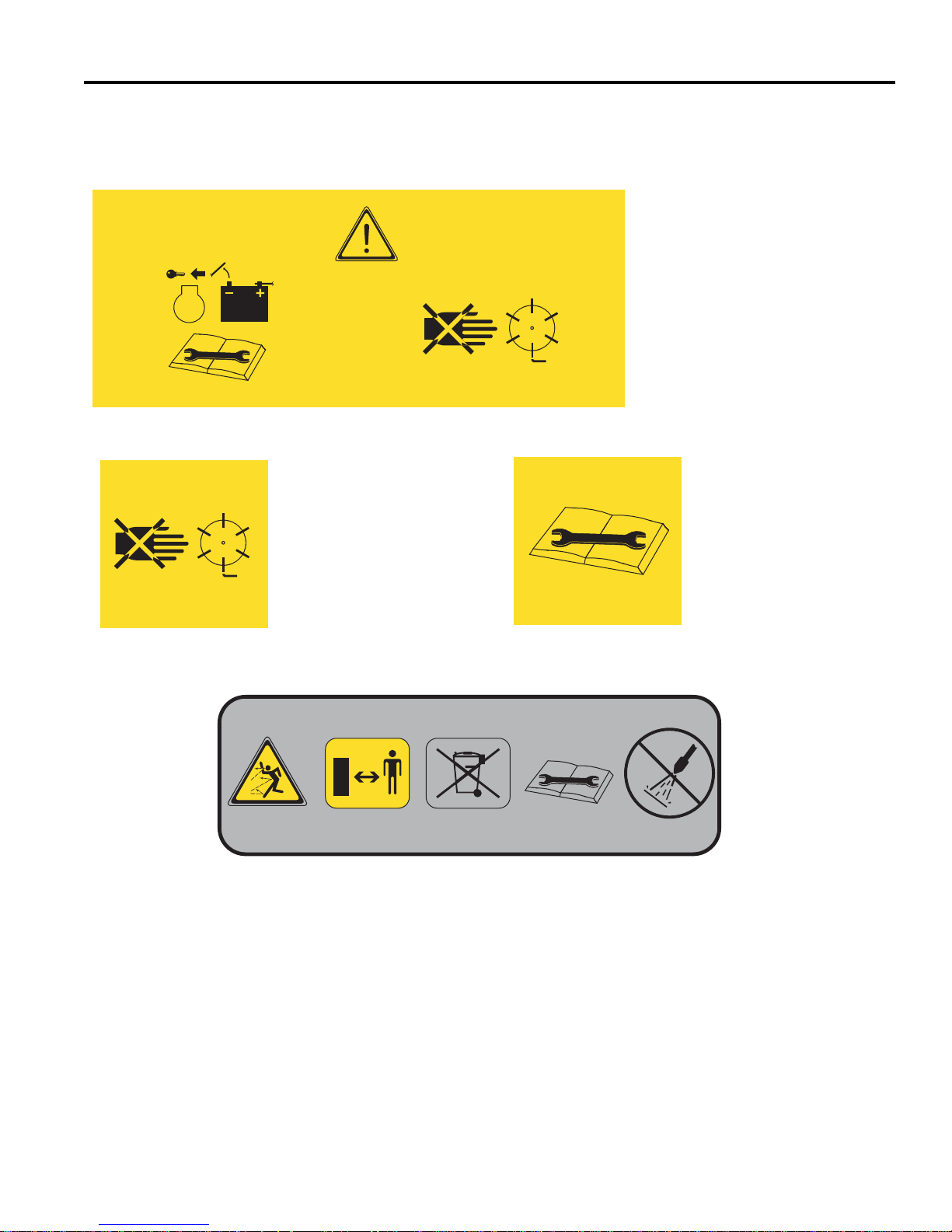
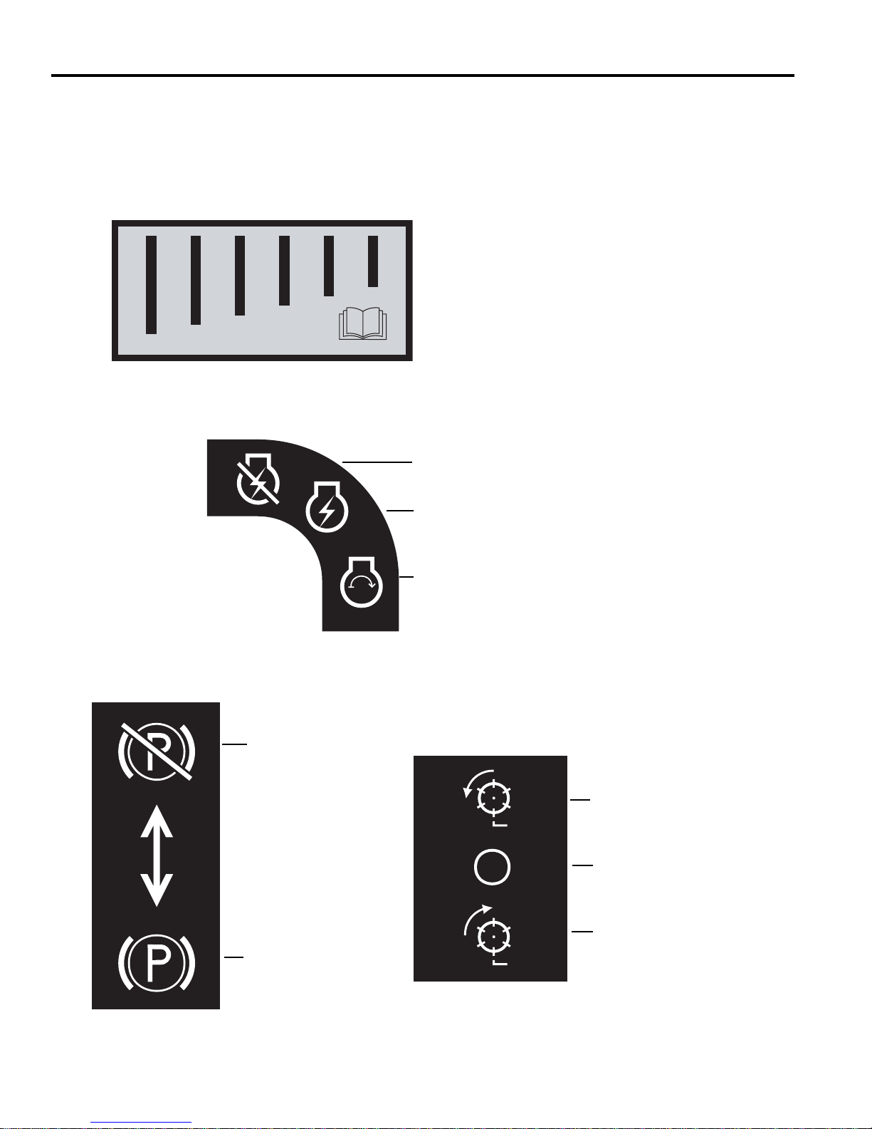
Familiarize yourself with the following decals. They are critical to the safe operation of the
mower . REPLACE DAMAGED DECALS IMMEDIA TELY.
STOP
4170001
4170321
4169840 REV A
en-13
2 SPECIFICATIONS
3002753
4172240
Read the manual before adjust ing
front roller weight.
Disengaged
Parking
Brake
Engaged
Reel Switch
Forward Rotation Position
OFF
Backlap Position
Key Switch
Off Position
Run Position
Energize Unit
Familiarize yourself with the following decals. They are critical to the safe operation of the
mower . REPLACE DAMAGED DECALS IMMEDIA TELY.
4104282
4165241
en-14

SPECIFICATIONS 2
Mower Weight
To Engage Traction.
1. Slide bail to the left.
2. Squeeze bail to handle.
063300 = 92.3 Kg
063301 = 110.4 Kg
063302 = 101.6 Kg
063303 = 109.3 Kg
063304 = 105.8 Kg
063311 = 113.0 Kg
063312 = 123.5 Kg
063313 = 101.3 Kg
063314 = 119.5 Kg
063315 = 114.9 Kg
en-15

3 CONTROLS
Engaged Disengaged
Parking Brake
O.P.C. Traction
Drive
Squeeze bail to handle
Power On
Fast Slow
Throttle
Power Up
Slide Bail Left
Power Off
!
!
A
B
C
D
E
F
G
H
!
3 CONTROLS
3.1 ICONS________________________________________________________________ ___
WARNING
Never attempt to operate the machine unless you have read the Safety and Operation
Manual, the Parts and Maintenance Manual and know how to operate all controls correctly.
Familiarize yourself with the icons shown above and what they represent. Learn the
location and purpose of all the controls before operating this mower.
3.2 HANDLE CONTROLS ______________________________________________________
A. Parking Brake – Used whenever the mower is left
unattended or as a service brake while transporting.
Always use transport tires when transporting up or
down hills.
H. LCD Controls - Used to navigate through menus.
WARNING
To prevent injury, always use transport tires when
transporting unit up or down hills.
B. Speed Paddle – Sets maximum traction drive
speed when O.P.C. Bail is engaged. Push (+) side
of lever to increase s peed. Push (-) side of lever to
decrease speed.
C. O.P.C. Bail – Slide bail slightly to the left and
squeeze bail to start traction motor. Traction motor
speed is increased as the bail moves towards the
handle. Release bail to stop unit.
D. Key Switch - The power switch turns the power on
and off. It has three positions OFF, RUN, and
START. Key swi tch must be in RUN posit ion to start
units equipped with Gen-Set power module.
E. Reel Switch - The reel switch is used to start and
stop the reel and to enable backlap.
F. Circuit Breaker - Used to protect controllers. Push
button in when tripped.
G. LCD Display - Used to display operating conditions.
Keep hands and feet away from the cutting unit to
prevent serious injury.
DANGER
Figure 3A
en-16

CONTROLS 3
G
J
K
L
!
3.3 LCD DISPLAY_____________________________________________________________
The LCD displays current functional values for the
operation of the Ecl ipse mower and sou nds one of thr ee
types of audible alerts. The LC D operates in one of two
modes, Operator Mode (Default), and Maintenance
Mode. Use of Maintenance mode req ui res a four dig it pi n
number.
Press either of the orange buttons (K or L) to change
screen display or chang e values. Push the right orange
button (K) to go forward in the display list or increase
setting value, and push th e left orange button (L) to go
back in the display list or decrease setting value. The
black button (J) is used to select, reset, or change
values.
Figure 3B
Audible Alerts indicate one of three conditions detected
by the LCD Display and a correspondi ng me ss age woul d
show on the display. A solid tone indicates low system
voltage. A fast beeping (2 pe r second) alert indic ates an
over voltage condition. A slow beeping (1 every 3
seconds) alert indicates mower is in backlap mode.
Alert Displays: In additi on to the standard displays for
each mode, there are four display s that are u sed to al ert
the operator/mechanic of a problem the needs to be
corrected.
Reel Motor Fault display is shown when a reel
motor short circuit is detected or the reel motor
current draw exceeds 30 Am ps for one second. Reel
motor will not operate until the problem is resolved.
Return mower to maintenance area for repair.
WARNING
Turn reel switch off, release bail, turn key to off
position, and disconnect battery connector before
checking for obstructions in reel.
Traction Motor Fault display is shown when a
traction motor shor t circuit is d etected or the traction
motor current draw exceeds 30 Amps for one
second. Traction motor will not operate until the
problem is resolve d. Return mower to maintenance
area for repair.
Operator Mode is used by the operator for system
voltage information, trav el speed, FOC setting, and reel
speed. Press the orange buttons (K and L) on the front
handle cover to toggle between the different displays.
Operator Mode is view o nly, no system settings c an be
changed.
If reel switch is placed into backlap position while in
operator mode, the reel motor will s top immediate ly, and
screen will display “Turn Backlap Switch Off”. Backlap is
only available in Superintend ant Mod e.
Standard start up
screen.
JACOBSEN
VERSION 1.27
Alert Displays
LOW BATTERY
41.8 VDC
OVERVOLTAGE
CHECK VOLTAGE
Low Voltage display is shown when system voltage
drops below 42 Volts DC for 30 seconds and an solid
tone alarm will sound . Press the black button (J) to
silence the alarm. Re turn mower to storage area or
install a fully charged battery pack. Reel motor will
not operate with low voltage on the display.
Overvoltage/Check Voltage display is shown when
system voltage is above 60 Volts DC and a fast (2
per second) beeping alarm will sound. If not
corrected, controlle r will sh ut down after 60 secon ds.
Check generator output before restarting system.
[See Section 9.3].
MOTOR FAULT
TRACTION
MOTOR FAULT
REEL
Figure 3C
Displays system
voltage.
Displays travel
speed of mower.
Displays fixed FOC
setting.
Displays reel rotation
speed.
Display if Reel Switch
is placed in backlap
position.
SYSTEM VOLTS
48.0 VDC
TRAVEL SPEED
3.4 MPH
FOC = 0.146
REEL SPEED
2200 RPM
TURN BACKLAP
SWITCH OFF
Figure 3D
en-17

3 CONTROLS
DO NOT SELECT
THIS MOTOR TYPE
Maintenance Mode is used by the maintenance to set
and adjust all functional values for the Eclipse Mower.
LCD displays available in Maintenance Mode are, factory
reset, system voltage, travel speed, reel speed, total
hours on machine, traction motor current draw, reel
motor current draw, total motor current draw, set mow
speed, set power source, maintenance hours, set reel
speed, set display units, calibrate speed paddle, and
calibrate bail lever.
To enter Maintenance Mo de, press both orange buttons
(K and L) when Jacobsen Version X.XX is on the display.
Use the orange buttons (K or L) to select and the black
button (J) to enter the digits for the Mechanic Mode pin.
NOTE: The PIN for Maintenance Mode is 6789.
NOTE: The Maintenan ce Mode PIN can be customi zed
to a setting of your choice. Please contact your Jacobsen
Dealer or Jacobsen Technical Support (1800-848-1636
Option 2) for complete instructions.
For backlap screens, see Section 10.4
Factory Reset: To reset controller to factory default
values, press either of the orange buttons (K or L) on the
front cover until the F actory Reset screen i s on the LCD
display. Press the black button (J) to reset values back to
factory default settings
Maximum Mow Speed3.4 Mph (5.5 kph)
Reel Speed................2200 rpm
Fixed FOC Setting .....0.146
Display units...............English
Fixed FOC Setting: To set the fixed FOC, press either of
the orange buttons (K or L) on th e front cover until the
FOC x.xxx CHANGE? screen is on the LCD display.
Press the black button (J) to enter set mode. Use the
orange buttons to raise (K) or lower (L) the FOC value to
the desired setting. press the black button to set speed.
Fixed FOC setting must be 0 or between 0.087 and 0.178
in. (2.2 and 4.5 mm). [See Section 3.4].
Maximum Mow Speed: To set the maximum mow
speed, press either o f the orange buttons (K or L) on the
front cover until the set max mow speed screen is on th e
LCD display. Press the black button (J) to enter set
mode. Use the orange buttons to raise (K) or lower (L)
the maximum mow speed to the desired speed. press the
black button to set speed.
Maximum mow speed must be betwee n 2.0 and 3.4
MPH (3.2 and 5.5 kph).
Fixed Reel Speed: To set the fixed re el speed, the F OC
setting must be set to 0, then press eit her of the orange
buttons (K or L) on the front cover until the set reel speed
screen is on the L CD display. Press the black butto n (J)
to enter set mode. Use the or ang e butt ons to r ai se (K) or
lower (L) the reel speed to the desired setting.
Fixed reel speed must be set between 1800 and
2200 rpm.
The Maximum Mow Speed and the Fixed Reel Speed are
used to determine the FOC (Frequency of Cut) [See
Section 3.4].
Power Source: To set power source, pres s eit her o f th e
orange buttons (K or L) on the front cover until the Power
Source screen is on the LCD display. Press the black
button (J) to cha nge powe r so ur ce .
Select either Genset Power or Battery Power.
Maintenance Hours: To reset maintenance hours, pre ss
either of the orange buttons (K or L) on the front cover
until the maintenance hours screen is on the LCD
display. Press the black button (J) to reset main tenance
hours to zero. The system can track a maximum of 999.9
hours.
Motor Type Select: Select the part number fo r the reel
and traction motors used on your equipment. The two
motors have different control voltage to output RPM
characteristics. The eclipse mower uses motor part no.
4160533 or 4205222. Do not select 4153940.
Part Number
4153940
Part Number
4160533
Part Number
4205222
Figure 3E
Display Units: To set the display units, press either of
the orange buttons (K or L) on the front cover until the
units screen is on the LCD display . Press the black button
(J) to enter set mode. Us e the orange buttons to selec t
the desired setting.
Units must be set to English or metric.
Calibrate Speed Paddle: Before calibrating the speed
paddle, check that paddle stops are properly adjusted
[See Section 5.3].To calibrate the paddle, press either of
the orange buttons (K or L) on the front cover until the
thumb lever screen is on the LCD display. Press the
black button (J) to enter set mode. Move the throttle
paddle through its entire range of movement to determine
minimum and maximum values.
Values displayed will change as controls are moved.
Calibrate Bail Lever: To calibrate the bail lever, press
either of the orange buttons (K or L) on the front cover
until the bail lever screen is on the LCD display. Press the
black button (J)
to enter set mode. Fully engage and
disengage the bail lever to determine minimum and
maximum values.
Values displayed will change as controls are moved.
en-18

CONTROLS 3
JACOBSEN
VERSION 1.27
TRAVEL SPEED
3.4 MPH
SYSTEM VOLTS
48.0 VDC
REEL SPEED
2200 RPM
Standard start up
screen.
Displays system
voltage.
Select reset to
factory defaults.
Confirm reset.
Displays
maintenance
hours.
Press both orange
buttons during
start screen.
Enter PIN.
Displays travel
speed of mower.
Displays reel
rotation speed.
Displays total
hours on unit.
Displays traction
motor current.
Displays reel
motor current.
Displays total
motor current.
Change Max
Mow Speed.
Mow Speed
Setting.
Select motor
used.
Motor
Selection.
Calibrate
Throttle
Paddle.
Display
Units.
Change
Display
Units.
Throttle
Paddle
Setting.
Calibrate
Bail Lever.
Bail Lever
Setting.
MNT 100.9 HR
RESET?
MAX MOW
< 3.4 MPH >
HOURS
250 HR
FOC = 0.146
CHANGE?
Fixed FOC
Setting.
Change FOC
Setting.
FOC = 0.146
< OK >
TRAVEL MOTOR
08.5 A
REEL MOTOR
08.5 A
MOTOR TOTAL
17.0 A
SET MAX
MOW SPEED
4160533/4153940
< OK >
UNITS
< ENGLISH >
THUMB LEVER
000 DONE 120
BAIL LEVER
040 DONE 096
ENTER PIN?
6789
FACTORY
RESET?
RESET?
NO YES
MOTOR TYPE
SELECT
Select power
Source.
Power Source
Selection.
GENSET POWER
< OK >
POWER SOURCE
CHANGE?
SELECT
UNITS?
THUMB LEVER
CALIBRATE?
BAIL LEVER
CALIBRATE?
Fixed Reel
Speed.
Fixed Reel
Speed setting.
REEL SPEED
< 2200 RPM >
REEL SPEED
2200 RPM
11 BLADES
CHANGE ?
09 BLADES
< DONE >
Number
of reel blade
selection.
Change
number of
reel blades.
Figure 3F
en-19

3 CONTROLS
3.4 FREQUENCY OF CUT ______________________________________________________
The FOC (Frequency of cut) is the distance, in inches
(mm), the machine travels forward between reel blades
contacting the bedknife. The FOC can be ad justed either
by changing the Fixed FOC setting or by changing the
maximum mow speed and the fixed reel speed on the
LCD display.
Adjust FOC with Fixed FOC setting
Changing the FOC setting to a value other than 0 will
enable the fixed FO C mode and disable the reel s peed
setting. As mower travel speed increases or decreases,
reel speed will automatically adjust as required to
maintain set FOC.
15 Blade Reel FOC Table
, Product No 63325, 63326, 63327, 63328, 63329, 63330, 63331, 63332 (Standard Reel)
Mow
Speed
2.00 0.078 0.076 0.074 0.072 0.070 0.069 0.067 0.065 0.064
(3.22) (1.987) (1.933) (1.882) (1.834) (1.788) (1.745) (1.703) (1.663) (1.626)
2.10 0.082 0.080 0.078 0.076 0.074 0.072 0.070 0.069 0.067
(3.38) (2.086) (2.030) (1.976) (1.926) (1.878) (1.832) (1.788) (1.747) (1.707)
2.20 0.086 0.084 0.082 0.079 0.077 0.076 0.074 0.072 0.070
(3.54) (2.186) (2.126) (2.071) (2.017) (1.967) (1.919) (1.873) (1.830) (1.788)
2.30 0.090 0.088 0.085 0.083 0.081 0.079 0.077 0.075 0.074
(3.70) (2.285) (2.223) (2.165) (2.109) (2.056) (2.006) (1.958) (1.913) (1.869)
2.40 0.094 0.091 0.089 0.087 0.084 0.082 0.080 0.079 0.077
(3.86) (2.384) (2.320) (2.259) (2.201) (2.146) (2.093) (2.044) (1.996) (1.951)
2.50 0.098 0.095 0.093 0.090 0.088 0.086 0.084 0.082 0.080
(4.02) (2.484) (2.416) (2.353) (2.293) (2.235) (2.181) (2.129) (2.079) (2.032)
2.60 0.102 0.099 0.096 0.094 0.092 0.089 0.087 0.085 0.083
(4.18) (2.583) (2.513) (2.447) (2.384) (2.325) (2.268) (2.214) (2.162) (2.113)
2.70 0.106 0.103 0.100 0.097 0.095 0.093 0.091 0.088 0.086
(4.35) (2.682) (2.610) (2.541) (2.476) (2.414) (2.355) (2.299) (2.246) (2.195)
2.80 0.110 0.107 0.104 0.101 0.099 0.096 0.094 0.092 0.090
(4.51) (2.782) (2.706) (2.635) (2.568) (2.503) (2.442) (2.384) (2.329) (2.276)
2.90 0.113 0.110 0.107 0.105 0.102 0.100 0.097 0.095 0.093
(4.67) (2.881) (2.803) (2.729) (2.659) (2.593) (2.530) (2.469) (2.412) (2.357)
3.00 0.117 0.114 0.111 0.108 0.106 0.103 0.101 0.098 0.096
(4.83) (2.980) (2.900) (2.823) (2.751) (2.682) (2.617) (2.555) (2.495) (2.438)
3.10 0.121 0.118 0.115 0.112 0.109 0.106 0.104 0.102 0.099
(4.99) (3.080) (2.996) (2.918) (2.843) (2.772) (2.704) (2.640) (2.578) (2.520)
3.20 0.125 0.122 0.119 0.116 0.113 0.110 0.107 0.105 0.102
(5.15) (3.179) (3.093) (3.012) (2.934) (2.861) (2.791) (2.725) (2.661) (2.601)
3.30 0.129 0.126 0.122 0.119 0.116 0.113 0.111 0.108 0.106
(5.31) (3.278) (3.190) (3.106) (3.026) (2.950) (2.879) (2.810) (2.745) (2.682)
3.40 0.133 0.129 0.126 0.123 0.120 0.117 0.114 0.111 0.109
(5.47) (3.378) (3.286) (3.200) (3.118) (3.040) (2.966) (2.895) (2.828) (2.764)
1800 1850 1900 1950 2000 2050 2100 2150 2200
Adjust FOC with Reel Speed Setting
1. Using the FOC charts, determine the maximum mo w
speed and fixed re el speed required for the desired
FOC.
2. Start the unit in Superintendant mode. [Section 3.3]
3. Set fixed FOC setting to 0
4. Set desired Maximum Mow Speed
5. Set desired Fixed Reel Speed
NOTE: Mow speed is measured in mph (kph), FOC is
measured in inches (millimeters).
Reel RPM
en-20

CONTROLS 3
11 Blade Reel FOC Table, Product No. 63300, 63301, 63302, 63303, 63311, 63312, 63313, 63314 (Standard Reel)
Mow
Speed
2.0
(3.22)
2.1
(3.38)
2.2
(3.54)
2.3
(3.7)
2.4
(3.86)
2.5
(4.02)
2.6
(4.18)
2.7
(4.35)
2.8
(4.51)
2.9
(4.67)
3.0
(4.83)
3.1
(4.99)
3.2
(5.15)
3.3
(5.31)
3.4
(5.47)
Reel RPM
1800 1850 1900 1950 2000 2050 2100 2150 2200
0.107
(2.709)
0.112
(2.845)
0.117
(2.98)
0.123
(3.116)
0.128
(3.251)
0.133
(3.387)
0.139
(3.522)
0.144
(3.658)
0.149
(3.793)
0.155
(3.929)
0.160
(4.064)
0.165
(4.199)
0.171
(4.335)
0.176
(4.47)
0.181
(4.606)
0.104
(2.636)
0.109
(2.768)
0.114
(2.9)
0.119
(3.032)
0.125
(3.163)
0.130
(3.295)
0.135
(3.427)
0.140
(3.559)
0.145
(3.691)
0.150
(3.822)
0.156
(3.954)
0.161
(4.086)
0.166
(4.218)
0.171
(4.35)
0.176
(4.481)
0.101
(2.567)
0.106
(2.695)
0.111
(2.823)
0.116
(2.952)
0.121
(3.08)
0.126
(3.208)
0.131
(3.337)
0.136
(3.465)
0.141
(3.593)
0.147
(3.722)
0.152
(3.85)
0.157
(3.978)
0.162
(4.107)
0.167
(4.235)
0.172
(4.363)
0.098
(2.501)
0.103
(2.626)
0.108
(2.751)
0.113
(2.876)
0.118
(3.001)
0.123
(3.126)
0.128
(3.251)
0.133
(3.376)
0.138
(3.501)
0.143
(3.626)
0.148
(3.751)
0.153
(3.876)
0.158
(4.001)
0.162
(4.127)
0.167
(4.252)
0.096
(2.438)
0.101
(2.56)
0.106
(2.682)
0.110
(2.804)
0.115
(2.926)
0.120
(3.048)
0.125
(3.17)
0.130
(3.292)
0.134
(3.414)
0.139
(3.536)
0.144
(3.658)
0.149
(3.78)
0.154
(3.901)
0.158
(4.023)
0.163
(4.145)
0.094
(2.379)
0.098
(2.498)
0.103
(2.617)
0.108
(2.736)
0.112
(2.855)
0.117
(2.974)
0.122
(3.093)
0.126
(3.212)
0.131
(3.33)
0.136
(3.449)
0.140
(3.568)
0.145
(3.687)
0.150
(3.806)
0.155
(3.925)
0.159
(4.044)
0.091
(2.322)
0.096
(2.438)
0.101
(2.555)
0.105
(2.671)
0.110
(2.787)
0.114
(2.903)
0.119
(3.019)
0.123
(3.135)
0.128
(3.251)
0.133
(3.367)
0.137
(3.483)
0.142
(3.6)
0.146
(3.716)
0.151
(3.832)
0.155
(3.948)
0.089
(2.268)
0.094
(2.382)
0.098
(2.495)
0.103
(2.609)
0.107
(2.722)
0.112
(2.835)
0.116
(2.949)
0.121
(3.062)
0.125
(3.176)
0.129
(3.289)
0.134
(3.402)
0.138
(3.516)
0.143
(3.629)
0.147
(3.743)
0.152
(3.856)
0.087
(2.217)
0.092
(2.328)
0.096
(2.438)
0.100
(2.549)
0.105
(2.66)
0.109
(2.771)
0.113
(2.882)
0.118
(2.993)
0.122
(3.103)
0.127
(3.214)
0.131
(3.325)
0.135
(3.436)
0.140
(3.547)
0.144
(3.658)
0.148
(3.768)
en-21

3 CONTROLS
9 Blade Reel FOC Table, Product No. 63303, 63312 (Optional Reel)
Mow
Speed
2.0 0.130 0.127 0.124 0.120 0.117 0.114 0.112 0.109 0.107
(3.22) (3.311) (3.222) (3.137) (3.057) (2.98) (2.908) (2.838) (2.772) (2.709)
2.1 0.137 0.133 0.130 0.126 0.123 0.120 0.117 0.115 0.112
(3.38) (3.477) (3.383) (3.294) (3.21) (3.129) (3.053) (2.98) (2.911)
2.2 0.143 0.140 0.136 0.132 0.129 0.126 0.123 0.120 0.117
(3.54) (3.643) (3.544) (3.451) (3.362) (3.278) (3.198) (3.122) (3.05) (2.98)
2.3 0.150 0.146 0.142 0.138 0.135 0.132 0.129 0.126 0.123
(3.7) (3.808) (3.705) (3.608) (3.515) (3.427) (3.344) (3.264) (3.188) (3.116)
2.4 0.156 0.152 0.148 0.144 0.141 0.137 0.134 0.131 0.128
(3.86) (3.974) (3.866) (3.765) (3.668) (3.576) (3.489) (3.406) (3.327) (3.251)
2.5 0.163 0.159 0.154 0.150 0.147 0.143 0.140 0.136 0.133
(4.02) (4.139) (4.027) (3.921) (3.821) (3.725) (3.634) (3.548) (3.465) (3.387)
2.6 0.169 0.165 0.161 0.156 0.153 0.149 0.145 0.142 0.139
(4.18) (4.305) (4.188) (4.078) (3.974) (3.874) (3.78) (3.69) (3.604) (3.522)
2.7 0.176 0.171 0.167 0.162 0.158 0.155 0.151 0.147 0.144
(4.35) (4.47) (4.35) (4.235) (4.127) (4.023) (3.925) (3.832) (3.743) (3.658)
2.8 0.183 0.178 0.173 0.168 0.164 0.160 0.156 0.153 0.149
(4.51) (4.636) (4.511) (4.392) (4.279) (4.172) (4.071) (3.974) (3.881) (3.793)
2.9 0.189 0.184 0.179 0.174 0.170 0.166 0.162 0.158 0.155
(4.67) (4.802) (4.672) (4.549) (4.432) (4.321) (4.216) (4.116) (4.02) (3.929)
3.0 0.196 0.190 0.185 0.181 0.176 0.172 0.168 0.164 0.160
(4.83) (4.967) (4.833) (4.706) (4.585) (4.47) (4.361) (4.258) (4.159) (4.064)
3.1 0.202 0.197 0.191 0.187 0.182 0.177 0.173 0.169 0.165
(4.99) (5.133) (4.994) (4.863) (4.738) (4.619) (4.507) (4.399) (4.297) (4.199)
3.2 0.209 0.203 0.198 0.193 0.188 0.183 0.179 0.175 0.171
(5.15) (5.298) (5.155) (5.019) (4.891) (4.768) (4.652) (4.541) (4.436) (4.335)
3.3 0.215 0.209 0.204 0.199 0.194 0.189 0.184 0.180 0.176
(5.31) (5.464) (5.316) (5.176) (5.044) (4.917) (4.798) (4.683) (4.574) (4.47)
3.4 0.222 0.216 0.210 0.205 0.199 0.195 0.190 0.186 0.181
(5.47) (5.629) (5.477) (5.333) (5.196) (5.066) (4.943) (4.825) (4.713) (4.606)
1800 1850 1900 1950 2000 2050 2100 2150 2200
Reel RPM
(2.845)
en-22

CONTROLS 3
7 Blade Reel FOC Table, Product No. 63304, 63315 (Standard Reel) and 63303, 63312 (Optional Reel)
Mow
Speed
2.0 0.168 0.163 0.159 0.155 0.151 0.147 0.144 0.140 0.137
(3.22) (4.258) (4.142) (4.033) (3.93) (3.832) (3.738) (3.649) (3.564) (3.483)
2.1 0.176 0.171 0.167 0.162 0.158 0.155 0.151 0.147 0.144
(3.38) (4.47) (4.35) (4.235) (4.127) (4.023) (3.925) (3.832) (3.743) (3.658)
2.2 0.184 0.179 0.175 0.170 0.166 0.162 0.158 0.154 0.151
(3.54) (4.683) (4.557) (4.437) (4.323) (4.215) (4.112) (4.014) (3.921) (3.832)
2.3 0.193 0.188 0.183 0.178 0.173 0.169 0.165 0.161 0.158
(3.7) (4.896) (4.764) (4.638) (4.52) (4.407) (4.299) (4.197) (4.099) (4.006)
2.4 0.201 0.196 0.191 0.186 0.181 0.177 0.172 0.168 0.165
(3.86) (5.109) (4.971) (4.84) (4.716) (4.598) (4.486) (4.379) (4.277) (4.18)
2.5 0.210 0.204 0.198 0.193 0.189 0.184 0.180 0.175 0.171
(4.02) (5.322) (5.178) (5.042) (4.913) (4.79) (4.673) (4.562) (4.456) (4.354)
2.6 0.218 0.212 0.206 0.201 0.196 0.191 0.187 0.182 0.178
(4.18) (5.535) (5.385) (5.243) (5.109) (4.981) (4.86) (4.744) (4.634) (4.528)
2.7 0.226 0.220 0.214 0.209 0.204 0.199 0.194 0.189 0.185
(4.35) (5.748) (5.592) (5.445) (5.306) (5.173) (5.047) (4.927) (4.812) (4.703)
2.8 0.235 0.228 0.222 0.217 0.211 0.206 0.201 0.196 0.192
(4.51) (5.961) (5.799) (5.647) (5.502) (5.364) (5.234) (5.109) (4.99) (4.877)
2.9 0.243 0.236 0.230 0.224 0.219 0.213 0.208 0.203 0.199
(4.67) (6.173) (6.007) (5.848) (5.699) (5.556) (5.421) (5.291) (5.168) (5.051)
3.0 0.251 0.245 0.238 0.232 0.226 0.221 0.216 0.210 0.206
(4.83) (6.386) (6.214) (6.05) (5.895) (5.748) (5.607) (5.474) (5.347) (5.225)
3.1 0.260 0.253 0.246 0.240 0.234 0.228 0.223 0.218 0.213
(4.99) (6.599) (6.421) (6.252) (6.092) (5.939) (5.794) (5.656) (5.525) (5.399)
3.2 0.268 0.261 0.254 0.248 0.241 0.235 0.230 0.225 0.219
(5.15) (6.812) (6.628) (6.454) (6.288) (6.131) (5.981) (5.839) (5.703) (5.573)
3.3 0.277 0.269 0.262 0.255 0.249 0.243 0.237 0.232 0.226
(5.31) (7.025) (6.835) (6.655) (6.485) (6.322) (6.168) (6.021) (5.881) (5.748)
3.4 0.285 0.277 0.270 0.263 0.256 0.250 0.244 0.239 0.233
(5.47) (7.238) (7.042) (6.857) (6.681) (6.514) (6.355) (6.204) (6.06) (5.922)
1800 1850 1900 1950 2000 2050 2100 2150 2200
Reel RPM
en-23
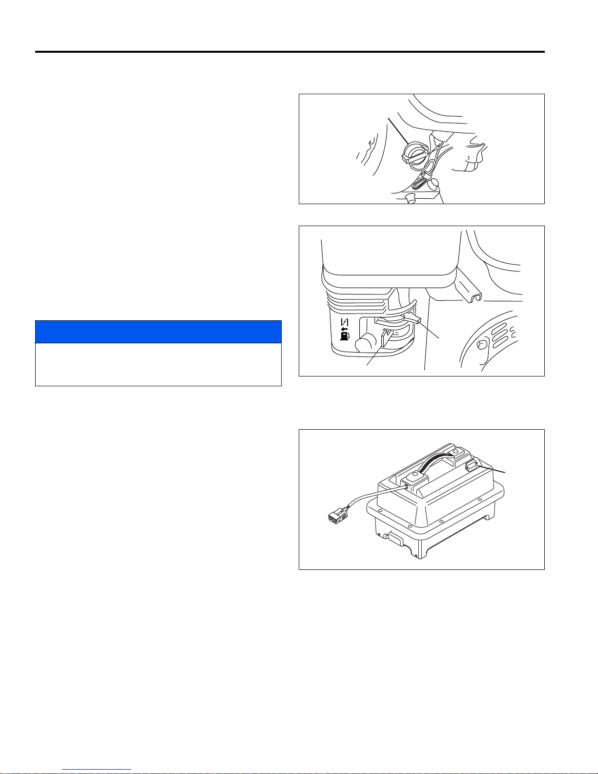
3 CONTROLS
OFF
ON
M
ON
OFF
N
P
R
3.5 GAS POWER MODULE CONTROLS __________________________________________
M. Engine Switch – The engine switch enables and
disables the engine ignition system. The engine
switch must be in th e ON position for the engine to
run. Turning the engine switch to the OFF position
stops the engine.
N. Choke Lever - The choke lever opens and closes
the choke valve in the carburetor. The CLOSED
position enriches the fuel mixture for starting a cold
engine. The OPEN p osition prov ides the correc t fuel
mixture for operation after starting, and for r estarting
a warm engine.
P. Fuel Valve Lever - Th e fuel valve opens an d closes
the connection between the fuel tank and the
carburetor. The fuel valve lever must be in the ON
position for the engine to run. When the engine is
not in use, leave the fuel valve lever in the OFF
position to prevent carburetor flooding, and to
reduce the possibility of fuel leaka ge.
Figure 3G
NOTICE
Before tipping mower back for adjustments, the fuel
lever must be moved to the OFF position to prevent
fuel from leaking into the crankcase.
Figure 3H
3.6 BATTERY POWER MODULE CONTROLS______________________________________
R. Battery Monitor - Located on the removable batter y
pack displays battery charge level.
Figure 3I
en-24

OPERATION 4
!
!
4 OPERATION
4.1 DAILY INSPECTI O N____________________ ____________________________________
2. Make sure the mower is adjusted to the required
CAUTION
The daily inspection should be performed only with
the parking brake engaged, and power connector
disconnected.
1. Perform a visual i nspec tio n o f the entire unit, loo k for
signs of wear, loose hardware, missing or damage d
components.
4.2 INTERLOCK SYSTEM (O.P.C.)________________________________________________
1. The Interlock System is inten ded to pr otect the oper ator and others from injury by stoppin g the reel and
drive mechanism as soon as the operator releases
the O.P.C. (Operator Presence Control) bail.
cutting height.
3. Make sure the machine is lubricated and the
transport tires are properly inflated.
4. Check the O.P.C. system.
5. Check motor connections are tight. Hand tighten
motor conections only, do not use wrenches to
tighten motor connection.
WARNING
Never operate equipment with the Interlock
System disconnected or malfunctioning. Do not
disconnect or bypass any switch.
2. To test the system:
a. Place mower on the kickstand.
b. Make certain reel switch is off.
3. Gen-Set Power Module: Start the engine.
4. Energize the unit.
a. Slide bail to the left and engage O.P.C. Bail.
b. The drive motor and the wheels will begin to turn.
c. Release the O.P.C. bail. The bail must
disengage, and drive motor must stop.
5. If the drive motor engages before th e O.P.C. bai l is
engaged or the drive mo tor continue to turn after the
O.P.C. bail is released; stop the unit immediately
and have the system repaired.
en-25

4 OPERATION
!
!
!
4.3 OPERATING PROCEDURES_________________________________________________
CAUTION
To help prevent injury, always wear safety glasses, leather work shoes or boots, a hard hat, and ear protection.
1. Under no circumstances should the unit be started
with operator or bystanders standing in front of the
reel.
2. Never run the engine in an enclosed area.
3. Keep hands and feet away from moving parts and
cutting units. If possible, do not make adjustments with
the engine running.
4. Do not operate mower or attachments with loose,
damaged, or missing components. Whenever
possible mow when grass is dry.
5. First mow in a test area to become thoroughly
familiar with the operation of the mower and control
levers.
NOTICE
To prevent damage to the reel and bedknife never
operate the reels when they are not cutting grass.
Excessive friction and heat will develop between the
bedknife and reel and damage the cutting edge.
6. Study the area to determine the best and safest
operating procedure. Consider the height of the
grass, type of terrain, and conditio n of the surface.
Each condition will require certain adjustments or
precautions. Only us e accessories and attachments
approved by Jacobsen.
9. Disengage the reel switch to stop blades when not
mowing.
10. Disengage the reel switch when crossing paths or
roadways. Look out for traffic.
11. Stop and inspect the equipment for damage
immediately after striking an obstruction, or if the
machine begins to vibrate abnormally. Have the
equipment repaired before resuming operation.
WARNING
Before you clean, adjust, or repair this equipment,
always disengage all drives, engage parking
brake, turf key switch OFF, and disconnect power
connector to prevent injuries.
12. Slow down and use extra care on hillsides. Use
caution when operating near drop offs.
13. Look behind and down bef ore backing up to be sure
of a clear path. Use care when approaching blind
corners, shrubs, trees, or other objects that may
obscure vision.
14. Never use your han ds to clean cutting units. Use a
brush to remove grass clippings from blades.
Blades are extremely sha rp and can cause serious
injuries.
7. Be aware of mower discharge direction and never
direct discharge of material toward bystanders.
Never allow anyone near the machine while in
operation. The owner/operator is responsible for
injuries inflicted to bystanders and/or damage to
their property.
CAUTION
Before mowing, pick up all debris such as rocks, toys,
and wire which can be thrown by the machine. Enter a
new area cautiously. Always operate at speeds that
allow you to have complete control of the mower.
8. Use discretion when mowing near gravel areas
(roadway, parking areas, cart paths, etc.). Stones
discharged from the mower may cause serious
injuries to bystanders and/or damage the
equipment.
en-26

OPERATION 4
A
B
C
D
E
F
G
H
OFF
ON
M
ON
OFF
N
P
4.4 STARTING/STOPPING______________________________________________________
1. Prepare power module to energize unit.
Battery Power Module: Disconnect battery charger
and connect power connector.
Gen-Set Power Module:
a. Check oil level and fuel supply then open fuel
valve lever (P).
b. Move the choke lever (N) to the CLOSED
position.
c. Set engine switch (M) to ON and power switch
(D) to RUN position.
d. Start the engine.
e. Once engine starts move c hoke lever (N) to the
OPEN position.
2. Make certain O.P.C. bail (C) is disengaged, reel
switch (E) is off, and parking brake (A) is engaged.
3. Turn power switch (D) to start position and re lease.
LCD display (G) should show startup display for 5
seconds, then switch to system voltage.
If system fails to initialize, check to see if power
connector is properly attached or if circui t breaker (F)
is tripped. Reset circuit breaker if necessary.
4. Check system voltage on LCD display (G). If the
system voltage screen is not on the display, press
either of the orange button s (H) to forward displ ay to
the correct screen. If system voltage is low,
recharge batteries or c heck generator output before
operating.
5. To mow or transport unit, push O.P.C. bail (C) to the
left and engage.
6. To stop the unit, release the O.P.C. bail, engage
parking brake, and set power switch to OFF
position.
7. Battery Power Module: Disconnect power
connector and connect battery pack to charger.
Figure 4A
Figure 4B
Gen-Set Power Module: Turn engin e switch (M) to
off position and close fu el valve (P).
en-27

4 OPERATION
!
1
2
3
4
5
First
Mowing
Second
Mowing
Third
Mowing
Fourth
Mowing
4.5 MOWING_________________________________________________________________
4. To assure complete , even cutting , overla p swaths by
WARNING
To prevent serious injuries, keep hands, feet, and
clothing away from cutting unit when the blades are
moving.
NEVER use your hands to clean cutting units. Use a
brush to remove grass clippings from b lades. Blades
can be sharp and could cause injuries.
To clear obstructions from cutting unit, disengage
O.P.C. bail, engage parking brake, turn off power
switch, and disconn ect power con nector then rem ove
obstruction.
1. Turn power OFF. Place mower on kickstand and
remove the transport wheels (If installed).
2. Engage the reel switch. Pu sh the mower forward off
kickstand. Start the unit.
1 to 2 in., (25 to 50 mm), then make one or more
passes around the perimeter of the green to clean
ragged edges and separate the putting green
surface from the apron.
5. For a more even playing surface and neater
appearance, alter the mowing pattern each time a
green is mowed. The patterns shown in Figu re 4D
are suggestions only, the operator or course
superintendant can arrange patterns to suit each
green.
6. Use caution while operating on hillside and dropoffs.
3. Position mower slightly off green.
a. Adjust traction speed paddle (B) to provide a
safe, comfortable walking speed.
b. Push handle down to lift the mower h ead above
the grass then engage the O.P.C. bail (C).
c. As the mower crosses the edge of the green,
lower the mower head to the ground, and
proceed across the green in a straight line.
When mowing lift up as required to keep han dle
centered in slots on handle stops. Do not push
down on handle when mowing or the mower
head may lift off the grass.
d. When the opp osite side of the green is reached,
push down of the handle to lift the mower head
without disengaging the O.P.C. bail, and proceed
off the green to turn around, or simply release
O.P.C. bail and turn around.
e. T o turn to the right, start by turning mower slightly
to the left (2). When the mower has moved
approximately 1/2 its own width to the left, swing
it around quickly to t he right (3 and 4), guiding
the mower with your right hand. This method
makes it possible to turn around quickly with very
few steps. [Figure 4C].
NOTICE
To prevent damage to the reel and bedknife never
operate the reels when they are not cutting grass.
Excessive friction and heat will develop between the
bedknife and reel and damage the cutting edge.
Figure 4C
Figure 4D
en-28
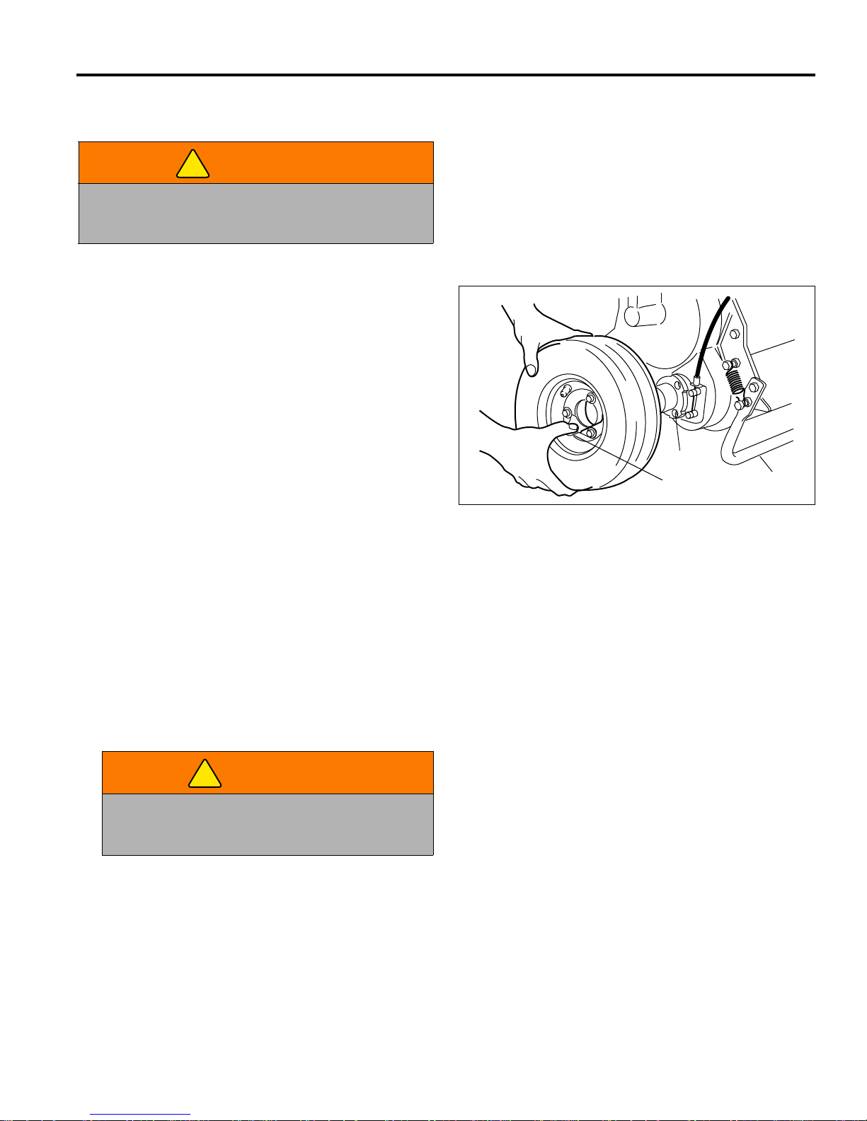
OPERATION 4
!
T
U
S
!
4.6 TRANSPORT WHEELS (OPTIONAL) __________________________________________
4. Always disengage reel switch prior to transporting
WARNING
Always engage parking brake and disconnect power
connector before installing or removing the transport
wheels.
Transport wheels are an optional accessory available
through your Jacobsen Dealer. Traction wheels are
recommended when not using the Mower Caddy to move
the mower from green to green.
1. Push and hold the kickstand agains t the ground the n
pull the mower handle, by the lift point, ba ck unti l the
mower rests on the stand (S).
2. To remove wheels, press retaining clip (T) away
from hub, and pull wheel off hub.
3. To install wheels, press retaining clip (T), place
wheel on hub, and turn the wheel backwards until
studs on back of wheel lin e up with holes in hub (U).
Push wheel in and release clip.
the mower more than a few feet.
5. Push the mower forwar d off the kickstand, start the
unit, and engage the O.P.C. bail.
6. When using a vehicle to tra nsport the mower, apply
parking brake, turn k ey switch OFF, and disconnec t
power connector.
Figure 4E
4.7 GRASS CATCHER _________________________________________________________
1. When the basket is about two thirds (2/3) full of grass
clippings, move the mower off the green.
2. Stop on a flat surface, disengage O.P.C. bail,
engage parking braket, turn key switch OFF, and
disconnect power connector.
3. Remove and empty the grass clippings from the
mower.
WARNING
To prevent serious injury, always disengage
O.P.C. bail and disconnect power connector
before emptying grass catcher.
en-29

4 OPERATION
!
4.8 DAILY MAINTENANCE _____________________________________________________
1. Park the mower on a flat, level surface. Engage
parking brake, and turn key switch to off position.
2. Grease and lubricate all points if required.
NOTICE
To prevent damage to reel motor, do not over grease
reel bearings. Damage of this nature is not covered by
the factory warranty.
3. To prevent fires, wash the mower after each use.
NOTICE
Battery Power Modules: Disconnect battery
connector and remove the battery pack from the
mower before washing.
a. Use only fresh water for cleaning your
equipment.
NOTICE
Use of salt wate r or effluent wa ter will en courage r ust
and corrosion of metal parts resulting in premature
deterioration or fail ure. Damage of this nature is not
covered by the factory warranty.
Gen-Set Power Module:
5. Fill fuel tank at the end of each operating day. Do
not fill above the fuel strainer shoulder. Close fuel
valve when unit is not in use.
Use clean, fresh, unleaded gasoline, 86 octane
minimum. Refer to the e ngine’s operator manual for
fuel recommendations when using blended fuel.
Handle fuel with care - it is highly flammable. Use an
approved container. The spout must fit inside the fuel
filler neck. Avoid using cans and funnels to transfer fuel.
WARNING
Never remove the fuel cap from the fuel tank, or add
fuel, when the engi ne is running or while th e e ngine is
hot.
Do not smoke when handling fuel. Never fill or drain
the fuel tank indoors.
Do not spill fuel and clean spilled fuel immediately.
Never handle or store fuel containers near an open
flame or any device that m ay create sparks and ignit e
the fuel or fuel vapors.
b. Do not use high pressure spray.
c. Do not spray water directly at electrical
connectors, generator, motors, or controller
d. Do not spray water into the cooling fins or the
engine air intake.
NOTICE
Do not wash a hot or running engine. Use
compressed air to clean the engine.
Battery Power Module:
4. Disconnect power connector and connect battery
pack to charger.
Be sure to reinstall and tighten fuel cap securely.
6. Store fuel according to local, state or federal
ordinances and recommendations from your fuel
supplier.
e. Check the engi ne oil at the s tart and e nd of e ac h
day, before starting the engine. If the oil level is
low, remove the oil filler cap and add oil as
required. Do not overfill.
en-30

ADJUSTMENTS (ALL UNITS) 5
!
!
HANDLE
BRAKE BAND
A
B
C
1-1/2”
(38 mm)
1-1/16 in.
(27 mm)
7/8 in.
(22 mm)
X
Y
Z
5 ADJUSTMENTS (ALL UNITS)
5.1 GENERAL _______ __ ___ ____________________________________________________
2. Replace, do not adjust, worn or damaged
WARNING
Before you adjust, clean, or repair this equipment,
always disengage all drives, engage parking brake,
turn key switch OFF, and disconnect power connector
to prevent serious injury.
1. Adjustments and maintenance should always be
performed by a qualified technician. If proper
adjustment cannot be made, contact an authorized
Jacobsen Dealer.
5.2 BRAKE __________________________________________________________________
A properly adjusted brake requi res 10 lbs. pull at top of
brake lever to engage and must have 1-1/2” (38 mm)
center to center when released.
components.
3. Long hair, jewelry, or loose fitting clothing may get
tangled in moving parts.
CAUTION
Be careful to prevent entrapment of the hands and
fingers between m oving and fix ed components of th e
machine.
4. Do not change speed limit settings or overspeed the
drive motors.
1. Minor adjustmen ts are made at the handle. Loose n
nut (A), turn nut (B) to adjust th e brake cable, then
tighten nut (A).
2. If adjustments cannot be made at the handle,
remove the transport wheel, and make the
adjustment at the brake band.
3. Loosen screw (C) and pull cable to obtain desired
brake tension. Tighten screw (C). Readj ust (A) and
(B).
Figure 5A
5.3 SPEED PADDLE STOPS ____________________________________________________
1. Loosen both nuts (X).
2. Adjust positive paddle stop (Y) to 7/8 in. (22 mm).
3. Adjust negative paddle stop (Z) to 1-1/16 in. (27
mm).
4. Tighten nuts (X) to lock adjustment.
After adjusting paddle stops, th e controller s peed paddle
calibration must be reset. [See Section 3.3].
Figure 5B
en-31

5 ADJUSTMENTS (ALL UNITS)
F
E
D
!
G
M
H
J
J
J
K
L
P
Fixed Head Mower Shown
Floating Head Mower Similar
P
P
N
5.4 HANDLE _________________________________________________________________
1. To adjust the angle of the handle bar (F), loosen
screw (D) on both sides of the mower and adjust the
handle bar to the desired position.
2. After adjusting handl e bar, adjust bracket (E) so that
the handle bar jus t rests on the bottom of the slot in
bracket. Tighten screw (D).
Figure 5C
5.5 TRACTION BELTS________________________ __ ___ __ _____________________ __ ___
.
CAUTION
To prevent permanent damage to the belt, do not
twist, fold, bend. or overtighten the belt.
1. To adjust belt (G), assemble 5/ 16-18 x 1” hex head
screw (K) and 5/16-18 hex nut (L) to bottom of
bearing bracket (H). Loosen nuts (J).
2. Place bedknife gauge bar (M) on top of roller and
under screw (K). Tighten screw (K) until belt (G)
deflects 1/10” (2.5 mm) with 1 ~ 2 lb (0.45 ~ 0.91
kg) load applied at mid span.
3. Tighten nuts (J) and remove 5/1 6-18 x 1” screw (K)
and lower nut (L).
4. Place hardware (K and L) in a safe place for future
adjustments.
5. To adjust belt (N), loosen pivot hardware (P), and
pivot motor housing towar ds front of mower until belt
deflects 1/10” (2.5 mm) with 1 ~ 2 lb (0.45 ~ 0.91
kg) load applied at mid span. Tighten hardware (P).
en-32
Figure 5D

ADJUSTMENTS (ALL UNITS) 5
!
U
R
V
S
W
Battery Power Module
Gen-Set Power Module
T
5.6 FRONT ROLLER WEIGHT ___________________________________________________
The weight on the front roller is adjustable. Adjust the
front roller weight as required to meet your turf needs.
CAUTION
To prevent in j ury or property da m age , pl ace mower on
kick stand before removing battery pack.
Full battery packs weigh approximately 55 lbs. Use
proper lifting techniques when moving them.
1. Battery Power Module: To adjust front roller weight,
disconnect power con necto r (R), and remove b attery
pack (S). Loosen hardware (T), place battery pack
back onto mower, take mower off kickstand, and slide
battery mounting tray (U) as required.
Gen-Set Power Module: Loosen engine mounting
hardware (V) and slide engine (W) as required.
2. To adjust the front roller weight:
a. To increase front roller weight, slide battery tray
(U), or engine (W) towards front of mower.
b. To decrease front roller weight, slide battery tray
c. Use the decal on the power module mount as a
3. Battery Power Module: When desired weight is
attained, measure distance from edge of power
module mount to tray (U). Rem ove battery pack (S).
Recheck measured dime nsion and tighten hardware
(R).
Gen-Set Power Module: Tighten engine mounting
hardware (V).
(U), or engine (W) towards rear of mower.
guide for adjusting the front roller weight.
Aligning the oil drai n (Gen-Set) or th e V-notch in
the battery tray (Battery Tray) with the desired
line on the decal allows for consis tent front r oller
weight setting.
Figure 5E
en-33

5 ADJUSTMENTS (ALL UNITS)
4.6
8.8
10.9
12.9
5.7 TORQUE SPECIFICATION___________________________________________________
NOTICE
All torque values included in these charts are approximate and are for reference only. Use of these torque values is
at your sole risk. Jacobsen is not responsible for any loss, claim, or damage arising from the use of these charts.
Extreme caution should always be used when using any torque value.
Jacobsen uses Grade 5 P lated bolts as standard, unless othe rwise noted. For tightenin g plated bolts, use the value
given for lubricated.
AMERICAN NATIONAL STANDARD FASTENERS
SIZE UNITS GRADE 5 GRADE 8 SIZE UNITS GRADE 5 GRADE 8
Lubricated Dry Lubricated Dry Lubri-
cated
#6-32 in-lb (Nm) – 20 (2.3) – – 7/16-14 ft-lb (Nm) 37 (50.1) 50 (67.8) 53 (71.8) 70 (94.9)
#8-32 in-lb (Nm) – 24 (2.7) – 30 (3.4) 7/16-20 ft-lb (Nm) 42 (56.9) 55 (74.6) 59 (80.0) 78 (105)
#10-24 in-lb (Nm) – 35 (4.0) – 45 (5.1) 1/2-13 ft-lb (Nm) 57 (77.2) 75 (101) 80 (108) 107 (145)
#10-32 in-lb (Nm) – 40 (4.5) – 50 (5.7) 1/2-20 ft-lb (Nm) 64 (86.7) 85 (115) 90 (122) 120 (162)
#12-24 in-lb (Nm) – 50 (5.7) – 65 (7.3) 9/16-12 ft-lb (Nm) 82 (111) 109 (148) 115 (156) 154 (209)
1/4-20 in-lb (Nm) 75 (8.4) 100 (11.3) 107 (12.1) 143 (16.1) 9/16-18 ft-lb (Nm) 92 (124) 122 (165) 129 (174) 172 (233)
1/4-28 in-lb (Nm) 85 (9.6) 115 (13.0) 120 (13.5) 163 (18.4) 5/8-11 ft-lb (Nm) 1 13 (153) 151 (204) 159 (215) 211 (286)
5/16-18 in-lb (Nm) 157 (17.7) 210 (23.7) 220 (24.8) 305 (34.4) 5/8-18 ft-lb (Nm) 128 (173) 170 (230) 180 (244) 240 (325)
5/16-24 in-lb (Nm) 173 (19.5) 230 (26.0) 245 (27.6) 325 (36.7) 3/4-10 ft-lb (Nm) 200 (271) 266 (360) 282 (382) 376 (509)
3/8-16 ft-lb (Nm) 23 (31.1) 31 (42.0) 32 (43.3) 44 (59.6) 3/4-16 ft-lb (Nm) 223 (302) 298 404 315 (427) 420 (569)
3/8-24 ft-lb (Nm) 26 (35.2) 35 (47.4) 37 (50.1) 50 (67.8) 7/8-14 ft-lb (Nm) 355 (481) 473 (641) 500 (678) 668 (905)
Dry Lubri-
cated
Dry
SIZE UNITS
Lubricated Dry Lubricated Dry Lubricated Dry Lubricated Dry
M4 Nm (in-lb) – – – – – – 3.83 (34) 5.11 (45) 2.0 (18)
M5 Nm (in-lb) 1.80 (16) 2.40 (21) 4.63 (41) 6.18 (54) 6.63 (59) 8.84 (78) 7.75 (68) 10.3 (910 4.0 (35)
M6 Nm (in-lb) 3.05 (27) 4.07 (36) 7.87 (69) 10.5 (93) 11.3 (102) 15.0 (133) 13.2 (117) 17.6 (156) 6.8 (60)
M8 Nm (in-lb) 7.41 (65) 9.98 (88) 19.1 (69) 25.5 (226) 27.3 (241) 36.5 (323) 32.0 (283) 42.6 (377) 17.0 (150)
M10 Nm (ft-lb) 14.7 (11) 19.6 (14) 37.8 (29) 50.5 (37) 54.1 (40) 72.2 (53) 63.3 (46) 84.4 (62) 33.9 (25)
M12 Nm (ft-lb) 25.6 (19) 34.1 (25) 66.0 (48) 88.0 (65) 94.5 (70) 125 (92) 110 (81) 147 (108) 61.0 (45)
M14 Nm (ft-lb) 40.8 (30) 54.3 (40) 105 (77) 140 (103) 150 (110) 200 (147) 175 (129) 234 (172) 94.9 (70)
en-34
METRIC FASTENERS
Non Critical
Fasteners
into
Aluminum

FIXED HEAD REEL ADJUSTMENTS 6
!
!
!
°
°
1/32”
(0.8 mm)
6 FIXED HEAD REEL ADJUSTMENTS
6.1 GENERAL _______ __ ___ ____________________________________________________
2. Replace, do not adjust, worn or damaged
WARNING
Before you adjust, clean, or repair this equipment,
always disengage all drives, engage parking brake,
turn power off and disconnect power connector to
prevent serious injury.
1. Adjustments and maintenance should always be
performed by a qualified technician. If proper
adjustment cannot be made, contact an authorized
Jacobsen Dealer.
6.2 REEL TO BEDKNIFE _______________________________________________________
(Pre-adjustment Check)
1. Check the reel bearings for end play or radial pl ay. If
there is any abnormal movem ent of the reel, up an d
down, or side to side, adjust, or replace com ponents
as needed.
components.
3. Long hair, jewelry, or loose fitting clothing may get
tangled in moving parts.
CAUTION
Be careful to prevent entrapment of the hands and
fingers between m oving and fix ed components of th e
machine.
4. Do not change speed limit settings or overspeed the
drive motors.
a. Dry, sparse conditions will requi re a wider ga p to
prevent heat buildup and damage to the reel and
bedknife.
b. High quality gras s with a good moisture content
requires a closer gap (near zero).
CAUTION
Handle the reel with extreme care to prev en t perso nal
injury and damage to the cutting edges.
2. Inspect the reel blades and be dknife to insure good
sharp edges without bends or nicks.
a. The cutting edges of the reel blades and bed-
knife must be sharp, free of burrs, and show no
signs of rounding off.
b. The bedknife and bedknife backing must be
securely tightened. The bedknife must be
straight and sharp.
c. A flat surface of at least 1/32 in. (0.8 mm)
minimum must be maintained on the front face of
the bedknife. Use a s tandar d f lat file to dress the
bedknife.
3. If wear or damage is beyond the point where the
reel or bedknife can be corrected by the lapping
process, they must be reground.
4. Proper reel-to-be dknife adjustment is critic al. A gap
of 0.001 to 0.003” (0.025 to 0.076 mm) must be
maintained across the entire length of the reel and
bedknife.
Figure 6A
5. The reel must be parallel to the bedknife. An
improperly adjusted reel will lose its sharp edges
prematurely and may result in serious damage to
the reel and bedknife.
6. Grass conditions will also affect the adjustment.
en-35

6 FIXED HEAD REEL ADJUSTMENTS
!
Rotation
Leading Edge
A
B
C
D
E
F
G
H
6.3 BEDKNIFE ADJUSTMENT __________________________________________________
1. Adjuster (A) is used to increase or decrease the
spring load on the bedk nife. Adjuster (B) is used to
move the bedknife to the reel or away from the reel.
2. Once the spring is totally collapsed as a result of
many adjustments, the bedknife cannot be moved.
Back-off adjuster (A) before adjusting (B).
3. For most applic ations, compress the spring to 1 in.,
(25 mm).
4. Start adjustment at the leading edge of the reel,
followed by the trailing e nd. The leading end of the
reel blade is the en d that passes over the bedknife
first during normal rotation.
CAUTION
Handle the reel with extreme care to prev en t perso nal
injury and damage to the cutting edges.
5. Turn adjuster (B) clockwise to bring the bedknife
closer to the reel or counterclockwise to back the
bedknife away from the reel.
a. Slide a feele r gauge or shim stoc k 0.001 - 0.00 3
in., (0.025 - 0.075 mm) between the reel blade
and the bedknife. Do not turn the reel.
b. Adjust the trailing end of the reel in the same
manner, then recheck the adjustment at the
leading end.
c. When the reel and bedknife are properly
adjusted, the reel will spin freely and will cut a
piece of newspaper along the full length of the
reel when the paper is held at 90° to the
bedknife.
Figure 6B
Figure 6C
6.4 CUTTING HEIGHT _________________________________________________________
Note: Make sure the bedknife is properly adjusted before
setting the cutting height. [See Section 6.3].
1. Push kickstand down and tip mower back on it’s
handle.
NOTICE
Gen-Set Power Modules: Do not leave the mower
tipped back for an extended length of ti me or oil may
migrate into the combustion ch amb er.
2. Loosen nuts (D) on both sid es just enough to allow
knob (C) to raise th e front r oller. Raise both sid es a n
equal amount.
3. Set gauge screw (G) to the desired cutting height
(F). Measure from the gauge bar (E) to the
underside of the screw head (G) then tighten wing
nut to lock the adjustment.
4. Place gauge bar between front roller and traction
roller, near the outer end of the rollers.
5. Slide screw head ove r bedknife (H) and adjust k nob
(C) so roller ju st contacts the gaug e bar. Tighten nut
(D).
6. Repeat Steps 4 and 5 on the opposite end of the
reel then tighten nuts (D). Recheck and readjust the
cutting height if necessary.
en-36
Figure 6D

FLOATING HEAD REEL ADJUSTMENTS 7
!
!
!
°
°
1/32”
(0.8 mm)
Leading Edge
LF025
7 FLOATING HEAD REEL ADJUSTMENTS
7.1 GENERAL _______ __ ___ ____________________________________________________
2. Replace, do not adjust, worn or damaged
WARNING
Before you adjust, clean, or repair this equipment,
always disengage all drives, engage parking brake,
turn power off and disconnect power connector to
prevent serious injury.
1. Adjustments and maintenance should always be
performed by a qualified technician. If proper
adjustment cannot be made, contact an authorized
Jacobsen Dealer.
7.2 BEDKNIFE-T O-REEL _______________________________________________________
(Pre-adjustment Check)
components.
3. Long hair, jewelry or loose fitting clothing may get
tangled in moving parts.
CAUTION
Be careful to prevent entrapment of the hands and
fingers between m oving and fix ed components of th e
machine.
4. Do not change speed limit settings or overspeed the
drive motors.
1. Check the reel bearings for end play or radial play.
There should be no end play or radial play. See Section
7.5.
CAUTION
To prevent personal injury and damage to the cutting
edges, wear gloves and handle the reel and bedknife
with extreme care.
2. Inspect the reel blades and bedknife to insure good
sharp edges without bends or nicks.
a. The leading edge of the reel blades must be sharp,
free of burrs and show no signs of rounding off.
b. The bedknife and bedknife backing must be
securely tightened. The bedknife must be straight
and sharp.
c. A flat surface of at least 1/32 in. (0.8 mm) minimum
must be maintained on the front face of the bedknife. Use a standard flat file to dress the bedknife.
3. If wear or damage is beyond the point where the reel
or bedknife can be corrected by the lapping process,
they must be reground.
4. Proper reel-to-bedknife adjustment is critical. A gap of
0.001 to 0.003” (0.025 to 0.076 mm) must be
maintained across the entire length of the reel and
bedknife.
a. Dry, sparse conditions will require a wider gap to
prevent heat buildup and damage to the reel and
bedknife.
b. High quality grass with a good moisture content
requires a closer gap (near zero).
Figure 7A
Figure 7B
5. The reel must be parallel to the bedknife. An
improperly adjusted reel will lose its sharp edges
prematurely and may result in serious damage to the
reel and bedknife.
6. Grass conditions will also affect the adjustment.
en-37

7 FLOATING HEAD REEL ADJUSTMENTS
GKV-1
B
C
7.3 BEDKNIFE ADJUSTMENT __________________________________________________
1. Read Section 7.2 before making the adjustment.
2. Start adjustment at the leading end of the reel,
followed by the trailing e nd. The leading end of the
reel blades is that end which passes over the
bedknife first during normal reel rotation.
3. Additional access to bedknife adjusting hardwar e (B
and C) can be obtained b y pres sing the l imit bracke t
(A) away from the reel as the mower is tipped ba ck
onto it’s handle. This allows the back side of the reel
to pivot down and away from the frame.
A
NOTICE
Gen-Set Power Modules: Do not leave the mower
tipped back for an extended length of ti me or oil may
migrate into the combustion ch amb er.
4. Use adjusters (B and C), to adjust gap. Loosen
bottom adjuster (C) and turn to p adjuster (B) down
(Clockwise) to close gap.
a. Slide a feeler gauge or shim stock 0.001” -
0.003” (0.025 - 0.075 mm) between the reel
blade and the bedknife. Do not turn the reel.
b. Adjust the trailing end of the reel to the same
gap in a similar manner then recheck the
adjustment at the leading end.
c. When the reel is properly adjusted to the
bedknife, the reel will spin free ly and you sho uld
be able to cut a piece of newspaper, along the
full length of th e reel, when the paper is held at
90° to the bedknife.
NOTICE
Avoid excessive tightening or serious damage may
result to bedknife and reel blades. Reels must turn
freely.
Figure 7C
Figure 7D
4. Return mower to upright position. Limit bracket (A)
is spring loaded and should latch into bracket on
reel.
en-38

FLOATING HEAD REEL ADJUSTMENTS 7
F
K
G
E
H
J
P
P
1-3/4”
(45 mm)
7.4 CUTTING HEIGHT _________________________________________________________
Note: Always make the reel to bedknife adjustment
before adjusting height of cut. (Sections 7.2 and 7.3).
1. Push kickstand down and tip mower back on it’s
handle.
NOTICE
Gen-Set Power Modules: Do not leave the mower
tipped back for an extended length of ti me or oil may
migrate into the combustion ch amb er.
1. Set desired cutting height on the gauge (E).
a. Measure distance between the underside of
screw head and gauge block surface (F).
b. Adjust screw (H) to obtain desired height then
tighten the wing nut.
2. Loosen the nuts on the front roller brackets (G) just
enough to allow the adjuster knob (K) to raise or
lower the front roller.
4. Slide the head of gauge sc rew (H) over the bedknif e
(L) and adjust the knob (K) to close the gap be twee n
the screw head and bedknife. Then tighten locknut
(G).
5. Repeat Steps 4 and 5 on opposite end. Complete
adjustment to one end before adjusting opposite end.
6. Tighten nuts (G) and recheck each end.
3. Place gauge (E) across bottom of front and rear
rollers near one end of roller.
7.5 REEL BEARING ___________________________________________________________
Any end play or radial play indicates bad bearings, a
weak tension spring or a backed off nut.
1. Check bearing housin g mounting hardware. Tighten
or replace components as required. Carefully clean
threads with degreaser.
2. Apply a medium streng th grade of Loctite to nu t (P),
then thread nut onto the reel shaft until the nut is
1-27/32” (46 mm) from the end of the reel shaft.
3. Fill reel bearing housings with NLGI - Grade O
grease after adjusting spring.
7.6 REEL ASSEMBLY REMOVAL ________________________________________________
The reel assembly can be removed for maintenance or to
use a different reel.
1. Remove hairpin and washer and slide the lift hangers
off the pins.
2. Disconnect motor electrical connectors and reel
ground wire. Whenever the reel motors are
disconnected from the harness, cover the
connectors on the motor to prevent debris from
entering motor.
3. Remove hairpin and f lat washer and lift panhard rod
off of reel bolt.
Gen-Set Power Modules: Do not leave the mower
tipped back for an extended length of time or oil may
migrate into the combustion chamber.
4. Tip the unit back onto the handle and s lide the reel
away from the mower.
5. Reel assembly is reverse of removal. Hand tighten
motor conections only, do not use wrenches to
tighten motor connection.
NOTICE
Figure 7E
Figure 7F
en-39

8 BATTERY POWER MODULE
!
TR016
!
TR017
8 BATTERY POWER MODULE
8.1 SAFETY _____________ ___ __ __ ________________________ _____________________
Batteries contain dilute sulfuric acid which can result in severe burns.
Hydrogen gas is for med within a b attery durin g the chargin g cycle. Hydr ogen in conce ntrations of 4 % and higher are
explosive and can be ignited by open fla me or an electrical spark. A battery explosion will cause sulf uric acid and
battery components to be thrown over a large area with considerable force.
Always observe the following warnings when working on or near batteries:
WARNING
The electrolyte in a st orage battery
is a dilute acid which can cause
severe burns to th e skin and eyes.
Treat all electrolyte spills to the body
and eyes with extended flushing
with clear water. Contact a physician
immediately. Always wear a safety
shield or approved safety goggles when charging
batteries.
Hydrogen is explosive in concentrations as low as 4%
and is generated in the charging cycle of electric
mowers. Because it is lighter than air, it will collect in
the ceiling of buildings necessitating proper
ventilation. Air exchanges of 5 changes per hour is
considered the minimum requirement.
Never smoke around batteries.
Never charge batteries in an area that has open flame
or electrical equ ipment that could ca use an electrical
arc.
Be sure that the key switch is off, all electrical
accessories are turned off and power connector is
disconnected before starting work on vehicle.
WARNING
Wrap wrenches with vinyl tape to
prevent the possibility of a dropped
wrench from ‘shorting out’ a battery,
which could resu lt in an explosion and
severe personal injury.
Electrolyte spills should be neutralized
with a solution of 1/4 cup (59.1ml) of
sodium bicarbonate ( baking soda) dissolved in 1-1 /2
gallons (5.7 liters) of water and flushed with water.
Never disconnect a circuit under load at a battery
terminal.
Wear appropriate protective clothing when working
with batteries. Electrolyte c an cause severe burns to
the eyes, skin and clothing.
Full battery packs weigh approximately 55 lbs. Use
proper lifting techniques when moving them.
Batteries, battery posts, terminals and related
accessories contain lead and lead compounds,
chemicals known to the State of California to cause
cancer and reproductive harm. Wash your hands
after handling
.
Remove all jewelry (watches, ring etc.)
8.2 GENERAL________________________________________________________________
The batteries used it this mower are sealed lead acid
(SLA) maintenance free type.
Temperature is important when conducting tests on a
battery and test results must be corrected to compensate
for temperature differences.
As a battery ages, it s ti ll per for ms adequately except tha t
its capacity is diminished. Capacity describes the time
that a battery can con tin ue to pr ov id e i ts des ign amperes
from a full charge.
en-40
A new battery must mature before it will develop its
maximum capacity. A battery has a maximum life,
therefore good maintenance is design ed to m ax imiz e th e
available life and reduce the factor s that c an redu ce the
life of the battery.

BATTERY POWER MODULE 8
1-1/2 GALLONS
CLEAR WATER
1/4 CUP SODIUM
BICARBONATE
(BAKING SODA)
2 GAL. GARDEN SPRAYER
(1 1/2 GAL. OF WATER)
NON-METAL
WAND
TR008
8.3 MAINTENANCE ___________________________________________________________
Tool List
Insulated wrench, 3/8”
Insulated wrench, 11/32”
Standard Screwdriver
Before charging batteries
Inspect the connector housings of the battery charger
and battery pack for dirt or debris. It is suggested to apply
white lithium grease to both terminals to prevent
corrosion.
Charge the batteries daily after use.
8.4 CLEANING BATTERIES________________________ __ ________________________ ___
When cleaning the batteries, do not use a water hose
without first spraying with a solution of sodium
bicarbonate (baking soda) and water to neutralize any
acid deposits.
Use of a water hose without first neutralizing any acid,
will move acid from the top of the batteries to another
area of the mower or sto rage facility where it will attack
the metal structure or the concrete/asphalt floor. After
hosing down the batteries, a residue will be left on the
batteries which is conductive and will contribute to the
discharge of the batteries.
The correct cleaning technique is to spray the top and
sides of the batteries with a solution of sodium
bicarbonate (baking soda) and water. This solution is
best applied with a garden type spray er equipped with a
non metallic spray wand. The solution should consist of
1/4 cup (59.1 ml) of sodium bicarbonate (baking soda)
mixed with 1-1/2 gal lons (5.7 l) of c lear wate r. In addition
to the batteries, special attention should be paid to
metallic components adjacent to the batteries which
should also be sprayed with the sodium bicarbonate
(baking soda) solution.
Allow the solution to sit for at least three minutes; use a
soft bristle brush or clo th to wipe the tops of the batte ri es
in order to remove any residue that coul d cause the self
discharge of the battery. Rinse the entire area wi th low
pressure clear water. Cleaning should take plac e yearly
or more often under extreme conditions.
Figure 8A
en-41

8 BATTERY POWER MODULE
!
!
P
P
Fuse Holder
8.5 BATTERY CHARGER _ ___ __________________________________________________
The battery charger is designed to fully charge the
AC Voltage
battery pack. Read the instru ction manual included with
the charger for proper operating procedure.
The charger is equipped with an input voltage selector
switch located on the rear of the charger. Determine what
Before charging, the following should be observed:
input voltage is used in your area and set switch
accordingly before connecting AC power cord. This
charger can be used with the following AC input voltages:
WARNING
Portable chargers should be mounted on a platform
100 - 130 V (Set voltage selector to 115 V (Position 1))
200 - 240 V (Set voltage selector to 230 V (Position 2))
above the ground, or in such a manner as to permit
the maximum air flow underneath and around the
charger. Serious damage to the charger, overheating
and potential for fire may result if the charger does not
have sufficient air flow.
NOTE: Charger will operate with either a 50 or 60 Hz
input voltage.
Make certain the AC power cord is equipped with an
appropriate plug for th e area you live in. The charger is
equipped with a grounding plug, do not attempt to
The charging must take place in an area that is well
defeat its functionality.
ventilated and capable of removing the hydrogen gas
that is generated by the charging process. A minimum of
five air exchanges per hour is recommended.
The charging connector components are in good
condition and free from d irt or debris. It is suggested to
apply white lithium grease to both terminals to prevent
An ungrounded electrical device may become a
physical hazard that could result in an electrical shock
or electrocution
WARNING
corrosion.
Note: The AC power cord included with the battery
The charger connector is fully inserted into the battery
pack receptacle.
The charger connector/cord set is protected from
damage and is locate d in an area to prevent injury that
may result from person nel running over or tripping ov er
the cord set.
charger is used with 115 V - 60 Hz (North America) inpu t
voltage only. If you live in an area where 115 V - 60 Hz
input voltage is not used, a ne w AC power cord mu st be
purchased locally.
The battery charger should fully c harge the batte ry pack
in approximately 5 hours with 115V AC input voltage.
Battery charging times may exceed 8 hours in areas
Install all chargers in accordanc e with the manufactur ers
where 100V AC input voltage is used.
instructions.
If the charger is operated in an outdoor location, rain
and sun protection must be provided.
Input Voltage Selector
osition
1
115V
Remove AC power cord f rom o utlet b efore conne cting or
disconnecting battery charger to battery pack.
The charging (DC) cord is equipped with a polarized
connector which fits into a matching receptacle on the
battery pack.
If the charger is not operating co rrectly, unplug charger
from both the AC outlet and the batte ry pack and check
the fuse. If a new fuse is required, order part number
4102780 from your Jacobsen Dealer. There is one
osition
2
230V
k in
se a spar
witches and
.
e a match, or cau
ks and
strik
uch as s
oom or
than 18
ts, s
ry during charging.
, locate in a r
mploys par
duce arcs and spar
4. Do not smoke,
pose or not less
pro
garage
vicinity of batte
5. Use only in a well ventilated area
O RAIN:
, that tend to
This equipment e
, if used in a
vided for the pur
AUX
relays
T EXPOSE T
therefore
urning
y leads only when
enclosure pro
- DO NO
and b
y
inches from the floor.
OSER A LA PLUIE.
e cords or wires immediately.
VANT D'UTILISER LE
ISQUE DE MELANGE GAZE
ectiv
: R
TICE A
CAUTION
ected to
NE PAS EXP
ity
replace def
LIRE LA NO
ith polar
CAUTION:
ADVERTISSEMENT
to
ead
EXPLOSIF.
CHARGEUR.
, refer to
uction
INTERACTER INCORPORA
MODEL:
BATCH: SERIAL NO:
INPUT:
WAR
NING - For continued protection
against fire, re
size and type fuse
place only with same
sconnect batter
WARNING - RISK OF EXPLOSIVE GAS MIXTURE
S - For a batter
ct charger output
1. Connect and di
supply cord is disconnected or arcing
y post - not conn
icle, first conne
may result.
veh
polarity lead to
TTERY LEAD CONNECTION
s - in accordance w
rounded batter
2. BA
installed in a
then opposite
in a vehicle
Disconnect chassis l
lead to ung
from battery; do not connect
lines.
automobile chassi
way
indication, and
y not installed
chassis a
ual.
or batter
carburetor or fuel
first. F
-charge battery - see instr
instruction man
3. Do not over
TED
.
manual
spare fuse included in the fuse holder.
Spare Fuse
Fuse
en-42

BATTERY POWER MODULE 8
!
PN
KEY
RD Wire
BK Wire
D
E
E
F
F
Og/Gn Wire
J
K
L
G
F
H
8.6 BATTERY INSTALLATION___________________________________________________
If the batteries have been cleaned and any acid in the
battery tray area neutralized, no corrosion to the
surrounding area should be present. Any corrosion found
should be immediatel y removed with a putty knife an d a
wire brush. The area should be washed with a solution of
sodium bicarbonate (baking soda) and water and
thoroughly dried before priming and painting with a
corrosion resistant paint.
The batteries should be placed into the battery tray as
shown in Figure 8B. Using batteries with the correct
physical size will prevent mov ement, but will not be t ight
enough to cause distortion of the battery case.
Inspect all wires and terminals. Clean a ny corrosion from
the battery terminals or the wire ter minals with a so lution
of sodium bicarbon ate (baking soda) and brush c lean if
required.
Use care to connect the battery wires as sho wn in F igur e
8C and tighten the battery post hardware securely.
Protect the battery terminals and battery wire terminals
with a commercially available protective coating.
Figure 8B
Battery Pack Assembly:
1. Install batteries into battery tray.
2. Fasten fuse cable ass embly (D) to battery pack with
screws, lockwashers, and nuts.
3. Fasten two cable jumper wires (E) into their
respective positions.
4. Thread the main cable (F) through the hole in the
side of the battery case lid (G).
5. Attach the main cable (F) to the batteries, and
battery monitor (M).
NOTE: There will be an Orange/Green wire with
insulated 1/4” terminal that is not used on the Eclipse
mowers. Seal end of the wire to prevent short-circuits.
6. Assemble the two halves of the battery case (G)
and (H), with screws (J), flat washers (K), and
battery casing straps (L).
Refer to Section 2.6 for battery specifications.
WARNING
Aerosol containers of b attery ter mina l protec tant must
be used with extreme care. Insulate the metal
container to prevent the metal can from contacting
battery terminals which could result in an explosion.
Figure 8C
Figure 8D
en-43

8 BATTERY POWER MODULE
!
A
B
C
8.7 REPLACING BATTERY PACK _______________________________________________
The battery pack (A) is designed to be easily lifted out
and replaced. This al lows the mower t o quickly retur n to
service should the batteries become discharged or fail.
Additional batter y packs are available as an ac cessory.
See Section 2.7
CAUTION
To prevent in j ury or property da m age , pl ace mower on
kick stand before removing battery pack.
Full battery packs weigh approximately 55 lbs. Use
proper lifting techniques when moving them.
To remove battery tray:
1. Park tractor on a solid, level area.
2. Set parking brake and remove key from switch.
3. Disconnect battery connector (B), place mower on
kickstand.
4. Push and hold battery release latch (C) down and
lift battery pack (A) away from mower.
5. Reverse procedure to install pack. Be sure pack is
completely seated on frame and secure.
Figure 8E
en-44
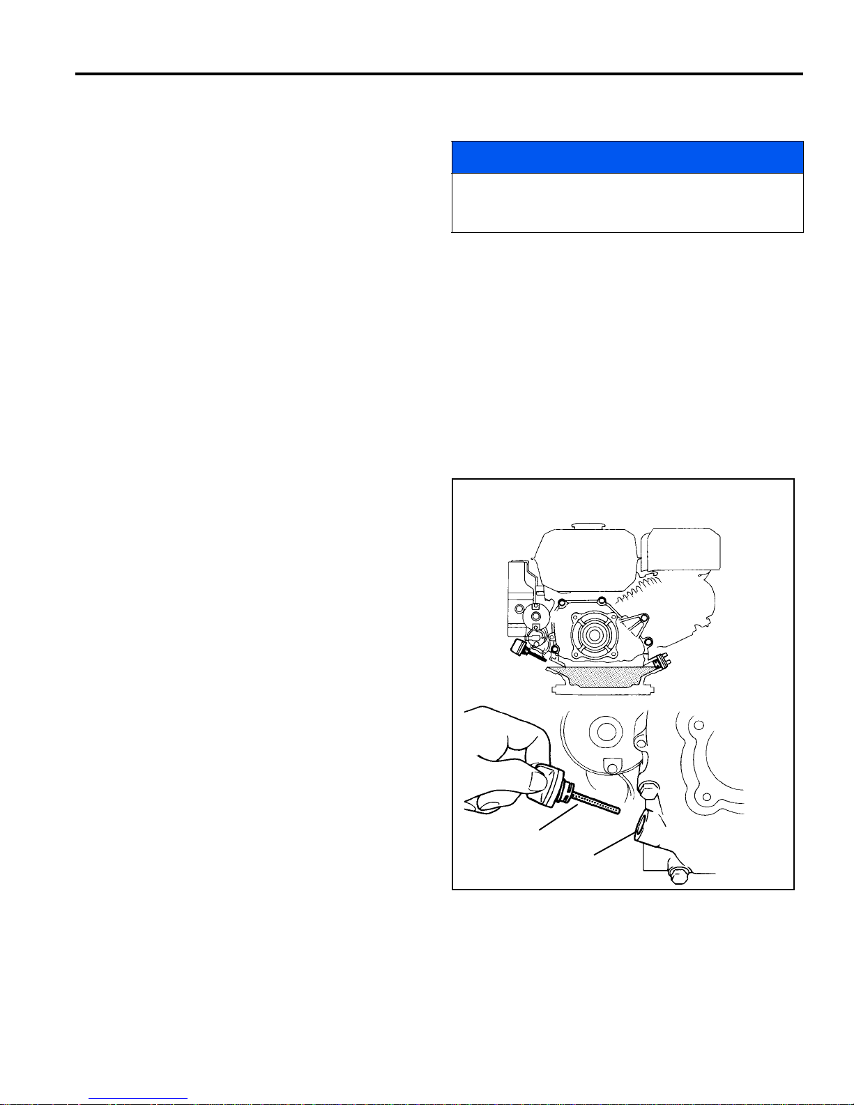
GEN-SET POWER MODULE 9
Upper Oil Level
Oil Filler Cap
9 GEN-SET POWER MODULE
9.1 ENGINE _________________________________________________________________
IMPORTANT: A separate Engine Manual, prepared by
the engine manufacturer, is supplied with the power
module. Read the engine manual carefully until you are
familiar with the operation and maintenance of the
engine. Proper attention to the engine manufacturer’s
directions will assure maximum service life of the
engine. To order replacement engine manuals contact
the engine manufacturer.
The mower is designed to operate and cut most
efficiently at the preset governor setting. Do not change
the engine governor settings or overspeed the engine.
During the break-in period, Jacobsen recommends the
following:
NOTICE
The proper break-in of a new engine can make a
considerable difference to the performance and life of the
engine.
1. Operate machine modestly for the first 25 hours.
2. Allow the engine to reach operating temperature before
operating at full load.
3. Change the engine oil after the first 20 hours of
operation.
4. Refer to Section 12.2 and Engine Manual for
specific maintenance intervals.
9.2 ENGINE OIL ______________________________________________________________
Check the engine oil at the start of each day, before starting
the engine. If the oil level is low , remove oil filler cap and add
oil as required.
Perform initial oil change after the first 20 hours of operation.
Change oil every 100 hours thereafter.
See the engine manufacturer’s Owners’s Manual for
detailed service information.
After adding or changing oil, start and run engine at idle with
all drives disengaged for 30 seconds. Shut engine off. Wait
30 seconds and check oil level. Add oil to bring up to FULL
mark on dipstick.
Use only SAE 10W30 engine oils with API classification
SG.SF/CC.CD
Figure 9A
en-45

9 GEN-SET POWER MODULE
!
9.3 ENGINE SPEED ___________________________________________________________
The engine speed is set at the factory for proper
generator output. However, engine speed should be
checked periodica lly, and adjusted to 59 volts. An output
voltage greater than 60 volts will cause an alarm to sound
and may cause system damage. Controller will shut
down after 60 seconds if the over voltage con diti on is not
corrected.
Adjustment should be made with the engi ne at opera ting
temperature using a volt meter.
1. Stop the engine and disconnect the generato r power
connector.
2. Remove the throttle lever cover.
3. Start the engine and adjust the engine throttle
position until an output voltage of 59 volts is
achieved at generator power connector.
4. Stop the engine and install throttle lever cover.
5. Connect generator power connector.
9.4 FUEL____________________________________________________________________
Handle fuel with care - it is highly flammable. Use an
approved container, the spout must fit inside the fuel filler
neck. Avoid using cans and funnels to transfer fuel.
WARNING
Never remove the fuel cap f rom the fuel tank, or add
fuel, when the engine is r un ni ng or whi le th e e ngi ne is
hot.
Do not smoke when handling fuel. Never fill or drain
the fuel tank indoors.
Do not spill fuel and clean spilled fuel imm edi ate ly.
Never handle or store fuel containers near an open
flame or any device that may create sparks and ig nite
the fuel or fuel vapors.
Be sure to reinstall and tighten fuel cap securely.
• Store fuel according to local, state or federal
ordinances and recommendations from your fuel
supplier.
• Never overfill or allow the tank to become empty.
• Use clean, fresh, regular grade, unleaded gasoline
minimum 86 Octane.
• See engine manual before using oxygenated (blended)
fuel.
• Do not fill above the fuel filler neck.
en-46
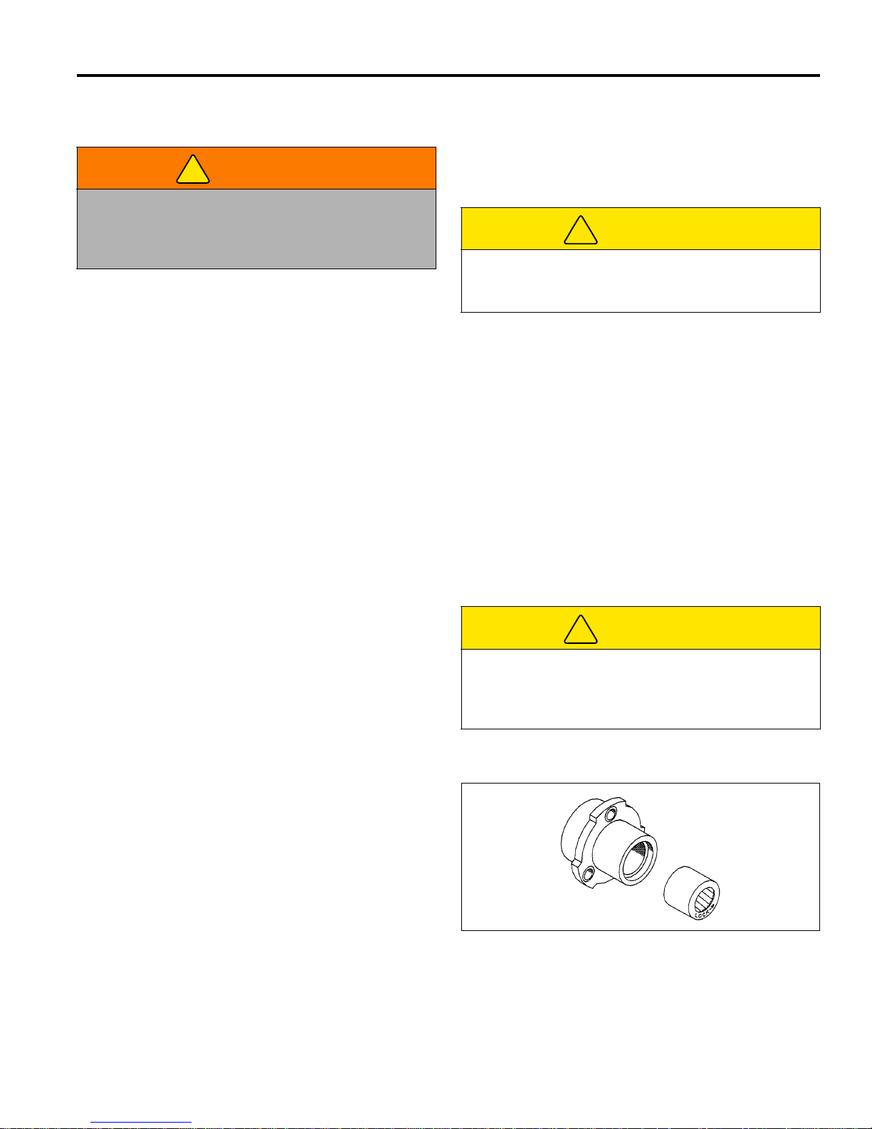
MAINTENANCE 10
!
!
!
10 MAINTENANCE
10.1 GENERAL ________________________________________________________________
e. Keep tires properly inflated (If installed).
WARNING
Before you adjust, clean, or repair this equipment,
always disengage all drives, engage parking brake,
turn power off and disconnect power connector to
prevent ser ious injury.
1. Adjustment and maintenance should always be
performed by a qualified technician. If proper
adjustments cannot be made, contact an Authorized
Jacobsen Dealer.
2. Inspect the equipment on a regular basis, establish a
maintenance schedule and keep detailed records.
a. Keep the equipment clean.
b. Keep all moving parts properly adjusted and lubri-
cated.
c. Replace worn or damaged parts before operating
the machine.
d. Keep shields in place and all hardware securely
fastened.
3. Long hair, jewelry or loose fitting clothing may get
tangled in moving parts.
CAUTION
Be careful to prevent entrapment of the hands and
fingers between m oving and fix ed components of th e
machine.
4. Use the illustrations in the Parts Catalog as reference
for the disassembly and reassembly of components.
5. Recycle or dispose of all hazardous materials
(batteries, lubricants, etc.) according to local, state or
federal regulations.
6. Do not change speed limit settings or overspeed the
drive motors.
7. After servicing reel or traction motor, check to be sure
motor connections are tight. Hand tighten motor
conections only, do not use wrenches to tighten
motor connection.
10.2 TIRES (OPTION)___________________________________________________________
1. Keep tires properly inf lated to prolo ng tire l ife. Che ck
pressure only when the tires are cool.
2. Use an accurate, low pressure tire gauge. 6 - 8 psi
(0.413-0.551 BAR)
Unless you have the proper training, tools and
experience, DO NOT attempt to mount a tire on a rim.
Improper mounting can produce an explosion that
may result in serious injury.
CAUTION
10.3 WHEEL BEARING ___________________ __ __ ___ _____________________ __ __ ___ ___
The bearing has the word LOCK and an arrow stamped
on the face. When replacing the bearing, make
absolutely certain that the bearing is being installed in the
proper direction or rotation.
For the Right wheel, install the bearing with the
“LOCK➨" arrow to the Outside of the bearing housing.
For the Left wheel, install the bearing with the “LOCK➨"
arrow to the Inside of the housing.
Figure 10A
en-47

10 MAINTENANCE
A
F
G
H
E
B
C
D
JACOBSEN
VERSION X.XX
TURN BACKLAP
SWITCH OFF
BACKLAP 5 MIN
< 50% >
Standard start up
screen
Display timer and
adjust backlap
reel speed
Place Reel Switch
in Backlap position.
Select yes or no.
Engage Bail and
release to start
backlapping
Press both orange
buttons during
start screen.
Enter PIN
Exit backlap
mode.
ENTER PIN?
XXXX
BACKLAP?
YES NO
ENGAGE BAIL
AND RELEASE
10.4 BACKLAPPING AND GRINDING _____________________________________________
Check for damage to the bedknife and reel blades.
Refer to (Section 5.2).
1. Determine if backl apping or grinding will resto re the
proper cutting edge.
2. For optimum performance use a bedknife grinder to
touch-up the blade then reas semble and adjust the
bedknife to the reel as described in (Section 5.2).
Disconnect motor connecti ons whenever turning the
reel by means other than the reel motor. When
tightening, hand tighten motor conections only,
do not use wrenches to tighten motor
connection.
3. Start unit in backlap mode.
a. Turn key (D) to start position and r elease. Press
both orange buttons (G and H) when Jacobsen
Version X.XX is on the display (A). Use the
orange buttons (G or H) to select and the black
button (F) to enter the four digits for the
Maintenances mode pin. [Section 3.3]
b. Place reel switch (E) in backlap position.
BACKLAP YES NO screen will display. Select
YES to backlap. If NO is selected, TURN
BACKLAP SWITCH OFF will be displayed.
c. Engage O.P.C. bail (C) an d release. Reel motor
will begin turning, a slo w beeping (1 every three
seconds) alarm will sound and a five minute
timer will start.
d. Adjust reel spe ed between 10% and 100% usin g
the orange buttons (G or H).
e. Apply lapping compound with a long handle
brush along the entire length of the reel, (180 grit
is recommended, Section 2.7).
f. Continue lapping and at the same time make a
fine adjustment on the reel and bedknife until
there is a uniform clearanc e along th e full le ngth
of the cutting edges.
Figure 10B
g. Exit backlap mode by allowing the five minute
timer to end, placing reel switch (E) in the OFF
position, moving the O.P.C. bail (C) or moving
the thumb lever (B).
h. Turn key switch (D) to off position.
4. Carefully and thoroughly remove all lapping
compound from reel and bedknife before running
the reel in forward direction.
en-48
Figure 10C
MAINTENANCE 10
!
!
10.5 STORAGE ________________________________________________________________
General
1. Wash the mower thoroughly and lubricate. Repair
and paint damaged or exposed metal.
2. Inspect the mower, tighten all hardware, replace
worn or damaged components.
3. Clean the tires thoroughly and store the tractor on
the kickstand so the load is off the tires. The front
roller should be resting on a wood board.
4. Keep the machine and all its accessorie s clean, dry
and protected from the elements during storage.
Never store equipment near an open flame.
5. Wash the reel and bedknife thoroughly, then repair
and paint any damaged or exposed metal.
6. Lubricate all fittings and friction points.
7. Backlap the reels t hen back the reel away from th e
bedknife. Apply a l ight coat o f rust prev entative oil t o
the sharpened edges of the reel and bedknife.
CAUTION
To prevent personal injury and damage to the cutting
edges, handle the reel with extreme care.
Battery Power Module:
During periods of storage, the batteries will need
attention to keep them maintained and prevent
discharge.
Battery Power Module After Storage
1. Fully charge the batteries.
2. Make certain that the tires are properly inf lat ed.
3. Remove all oil from the reels and bedknife. Adjust
bedknife and cutting height.
Gen-Set Power Module:
1. While the engine is warm, re move drain plug, drain
the oil from the crankca se . Ins tall drai n pl ug a nd refi ll
with fresh oil. Torque drain plug to 22 ft. lb. (30 Nm).
2. Clean exterior of engine. P aint the exposed metal or
apply a light coat of rust preventative oil.
3. To prevent the build-up of gu m residues and vanish
films, fill the tank with stabilized fuel. Use an antioxidant fuel conditioner, such STA-BIL®. Read and
follow the instructions on the container.
4. Operate the engine for about 5 minutes to dist ribute
the treated fuel. Stop the engine, close the fuel sh utoff valve and let the engine cool. Drain fuel.
5. Remove the spark plug and pour about one ounce
of SAE 30 oil into the cylinder. Crank engine slowly
by hand to distribute oil over the cylinder wall.
Replace the spark plug.
6. Pull the starter rope slowly until resistance is felt.
Continue pulling until the notch on the starter pulley
aligns with the hole on the recoil starter. At this
point, the intake and exhaust valves are closed.
In high temperatures the chemical reaction is faster,
while low temperatures cause the chemical reaction to
slow down. If a fully charged battery is allowed to sit
unused, it will slowly self discharge. When the battery
charge level falls to 8 0% of its full charge, it should be
recharged.
If a battery is allowed to fully discharge and is left in a
discharged state, sulfation takes place on and withi n the
plates. This condition is not reversible and will cause
permanent damage to the battery. In order to prevent
damage, the battery should be recharged.
In winter conditions, the batt ery must be fully c harged to
prevent the possibility of freezing . A fully ch arged battery
will not freeze in the most severe of winter climates.
Although the chemical reaction is slowed in cold
temperatures, the batt ery must be stored fully charged,
and disconnected from any circuit that could discharge
the battery. Disconnect the charging plug from the mower
power connector. The batteries must be cleane d and all
deposits neutralized and r emoved from the battery case
to slow self d ischarge. The batteries s hould be te sted or
recharged at thirty day intervals.
Gen-Set Power Module After Storage
1. Check or service the fuel filter and air cleaner.
2. Check oil level in the engine crankcase.
3. Fill the fuel tank with fresh fuel. Open fuel shut off
valve.
4. Remove all oil from the cutting edges. Readjust
reel-to-bedknife and cutting height.
5. Start the engine and allow enough time for the
engine to become properly warmed and lubricated.
WARNING
Never operate the engine without prope r ventilation;
exhaust fumes can be fatal if inhaled.
en-49

11 TROUBLESHOOTING
11 TROUBLESHOOTING
11.1 GENERAL________________________________________________________________
The troubleshooting cha rt below lists basic problems that may occur during start-up and operation. F or more detailed
information, contact your area Jacobsen Dealer.
Symptoms Possible Causes Action
Unit does not have
power
Engine will not
start.
Engine hard to start
or runs poorly,
looses power or
stalls.
Mower does not
react properly to
O.P.C. Lever
Reel does not cut,
or cuts unevenly
1. Power Connector Disconnected 1. Connect Power Connector
2. Batteries Discharged 2. Fully charge battery pack
3. Engine not running 3. Start engine before attempting to energize unit
4. 50 Amp fuse blown 4. Open battery tray and check fuse. Replace
5. 20 Amp circ uit breaker tripped 5. Reset
6. Defective Battery 6. Perform load test, replace batteries as needed
7. O.P.C. bail engaged 7. Disengage bail and restart
1. Choke in wrong position 1. See Engine Manual
2. Empty fuel tank or dirty fuel 2. Drain and refill fuel tank with fresh, clean fuel
3. Fuel Shut-off valve closed 3. Open fuel shut-off valv e
4. Engine / Spark Plug 4. See Engine Manual
5. Engine switch off 5. Turn en gine switch to On
1. Choke in wrong position 1. See Engine Manual
2. Dirty or incorrect fuel 2. Refill with proper grade, clean fuel
3. Loose Wiring 3. Check spark plug wire
4. Air intake plugged 4. Clean air intake and air cleaner
5. Vent in fuel cap plugged 5. Clean fuel cap
1. Power switch not on 1. Follow proper start-up procedure
2. Parking brake engaged 2. Disengage parking brake
3. Reel switch in off position 3. Turn reel switch on
4. Broken Belt 4. Check and replace belts as needed
5. Bail lever not properly calibrated 5. Calibrate bail lever
6. Traction motor fault 6. Check LCD display, service traction motor
1. Reel to bedknife not adjusted 1. Adjust Reel to Bedknife
2. Reel switch in off position 2. Turn reel switch on
3. Reel motor fault 3. Check LCD display, service reel motor
4. Low battery charge 4. Fully charge battery pack
5. Over Voltage condition 5. Adjust generator output
en-50

MAINTENANCE & LUBRICATION CHARTS 12
!
12 MAINTENANCE & LUBRICATION CHARTS
12.1 GENERAL ________________________________________________________________
The mower was designe d for minimum lubricati on. Over
greasing will produce high loads on the bearings;
thereby reducing the performance of the machine. Over
greasing reel bearings may also damage the electric
motor; voiding the warranty.
All maintenance intervals must be performed more
frequently when operating in extremely dusty conditions.
3. For smooth operation of pivot points and other
friction points, apply several drops of SAE 30 oil
every 50 hours or as required.
4. Do not over grease reel bearing (L2). Damage to
the motor may result. This damage is not covered
under the warranty.
5. To lubricate point (L4), remove L.H. transport wheel
and mounting bracket (E) to gain access to fitting.
WARNING
Turn the traction drum if pulley (F) is blocking the
fitting then insert grease gun through hole and
Before you clean, adjust, or repair this equipment,
disengage all drives, engage parking brake, turn power
off and disconnect power connector to prevent injuries.
carefully apply grease.
6. To lubricate points (L7), remove tran sport wheel, nu t
(A) from end of shaft and pull wheel hub (D) off.
Remove collar (B) and bushing (C) then pack
1. Always clean grease fittings before and after
bearing with lithium grease.
lubrication.
2. Lubricate with grease that meets or exceeds NLGI
Grade 2 LB specifications. Apply grease with a
manual grease gun and fill slowly until grease
begins to seep out. Do not use compressed air.
12.2 MAINTENANCE CHART_______ __ __ _________________________________ __ __ _____
Recommended Service and Lubrication Intervals
● Charge Batteries
Belt Tension
Air Cleaner
▼ Combustion Chamber
▼ Engine Oil
▼ Fuel Line
▼ Fuel Strainer
▼ Spark Plug
▼ Valve Clearance
Grease Locations
L1 - L5
L6-L7
Every
3-4
Hours
AR I C
Every
20
Hours
IC
IR* R II
A - Adjust C - Clean I - Inspect L- Lubricate R - Replace AR - As Required
* Indicates initial service for new machines.
I Manual grease gun with NLGI Grade 2 (Service Class LB).
II Engine Oil - See 9.2
Every
50
Hours
LLI
Every
100
Hours
C
A/R
Every
250
Hours
C
A
Yearly Lubricant
I-A
R - 2yrs
L I
Type
● Battery Power Module
▼ Gen-Set Power Module
en-51

12 MAINTENANCE & LUBRICATION CHARTS
F
C
D
B
A
L
4
L
6
L
6
L
7
E
●
●
●
●
●
L
3
L
L
5
2
L
1
L
L
5
L
5
2
L
2
L
1
L
1
L
1
L
1
L
1
L1 - Reel Roller Bearing
L
2 - Reel Motor Bearing Housing
L
3 - Right Side Traction Drum Bearing Housing
L
4 - Left Side Traction Drum Bearing Housing
L
5 - Reel Bearing Housing
L
6 - Pulley Shaft Bearing
L
7 - Hub
Wheel Hub Assembly
Pulley Shaft Assembly
12.3 LUBRICATION CHART _____________________________________________ __ ____ __
en-52

PARTS CATALOG 13
13 PARTS CATALOG
13.1 HOW TO USE THE PARTS CATALOG _________________________________________
Abbreviations
N/S - Not serviced separately, can only be obtained
by ordering main component or kit.
AR -Variable qua ntity or measurement is require d
to obtain correct adjustment.
Indented Items
Indented items indicate component parts that are
included as part of an assem bly or another component.
These parts can be ordered separate ly or as part of the
main component.
Symbols such as ●, next to the item number,
indicate that a note ex ists which contain additio nal
information important in ordering that part.
Item Part No. Qty Description Serial Numbers/Notes
● 1 123456 1 Mount, Valve Indicates a piece part
2 789012 1 Valve, Lift Includes Items 2 and 3
3 345678 1 • Handle Serviced part included with Item 2
4 N/S 1 • Seal Kit Non serviced part included with Item 2
5 901234 1 Screw, 1/4-20 x 2” Hex Head
13.2 TO ORDER PARTS_________________________________________________________
1. Write your full name and complete address on the
order.
2. Explain where and how to make shipment.
3. Give product number, name and serial number that is
stamped on the name plate or serial plate of your
product.
4. Order by the quantity desired, the part number, and
description of the part as given in the parts list.
Use of other than Jacobsen authorized parts will void the warranty.
5. Send or bring the order to an authorized Jacobsen
Distributor.
6. Inspect all shipments on receipt. If any parts are damaged or missing, file a claim with the carrier before
accepting.
7. Do not return material without a letter of explanation,
listing the parts being returned. Transportation
charges must be prepaid.
13.3 PARTS CATALOG TABLE OF CONTENTS______________________________________
1.1..............................Handle and Controls.................................................................................................................................... 54
2.1..............................Handle Attach............................................................................................................................................... 56
3.1..............................Handle Cover................................................................................................................................................ 57
4.1..............................Power Module Mounting Plate.................................................................................................................... 58
5.1..............................Frame Assembly.......................................................................................................................................... 60
6.1..............................Frame Assembly.......................................................................................................................................... 62
7.1..............................Lower Unit .................................................................................................................................................... 64
8.1..............................Reel ............................................................................................................................................................... 66
9.1..............................Grass Shield and Roller Brackets................................. ..... ...... .................................................................. 68
10.1............................Floating Head Reel Connection.................................................................................................................. 70
11.1............................Outer Reel Assembly................................................................................................................................... 72
12.1............................Inner Reel Assembly.................................................................................................................................... 74
13.1............................Differential and Rollers................................................................................................................................ 76
14.1............................Parking Brake and Wheels.......................................................................................................................... 78
15.1............................Belts and Drive Motors................................................................................................................................ 80
16.1............................Clamps and Wire Harness........................................................................................................................... 82
17.1............................Genset Power Source.............................. ...... ...... ..... ...... ............................................................................. 84
18.1............................Battery Power Source.................................................................................................................................. 86
19.1............................Battery Case................................................................................................................................................. 88
20.1............................Fixed Head Motor Clamp............................................................................................................................. 90
21.1............................Floating Head Motor Clamp........................................................................................................................ 91
22.1............................Electrical Schematic.................................................................................................................................... 92
22.1............................Wiring Diagram ............................................................................................................................................ 94
en-53

11524 WILMAR BLVD,
CHARLOTTE, NC 28273
®
kg kW
1-800-848-1636 (US)
PRODUCT OF U.S.A.
A Textron Company
ÖNSÖZ
Bu kılavuz güvenlik, çalıştırma, bakım, sorun giderme
yönergeleri ve yeni Jac obsen makinen iz iç in pa rça lis tesi
içermektedir.
Seri numara plakas ı kasan ın arka kol demir inde bu lunur.
Jacobsen, kol ay başvuruda bulunmak için aşağıdaki bu
rakamları kaydetmenizi önerir.
Makinenizi çalıştırmadan önce, siz ve görev verdiğiniz
tüm operatörler kılavuzu tamamen dikkatlice okumalıdır.
Güvenlik, çalıştırma ve bakım yönergelerine uyarak
ekipmanınızın ömrün ü uzatır ve en fazla verimi almaya
devam edersiniz.
Ek bilgi gerekli olursa, Jacobsen Satıcınıza başvurun.
Önerilen Saklama Kilavuzu
Ekipmanınızı tam olarak çalışır ve verimli tutmak için Jacobsen en çok kullanılan bakım öğelerinin bir stoğunu
tutmanızı önerir.
Aşağıdaki materyallerden herhangi birini sipariş etmek
için:
1. Sipariş formuna tam adınızı ve eksiksiz adresinizi
yazın.
2. Sevkıyatın nereye ve nasıl yapılacağını açıklayın:
❑ UPS ❑ Normal Posta
3. İstediğiniz miktar, parça numarası ve parçanın
açıklaması ile sipariş verin.
4. Siparişinizi yetkili Jacobsen Satıcınıza gönderin veya
getirin.
❑ Ertesi Gün Teslimat ❑ İki Gün Sonra Teslimat
Servis Parçaları
Miktar Par ça No. Açıklama Miktar Parça No. Açıklama
4102780 50 Amp Sigorta 2811106 Makara Kayışı için Motor
4169341 25 Amp Şalter 2811070 Çekme Tamburu Kayışı için Makara
4131618 Kontak Anahtarı
Servis Destek Malzemesi
Miktar Parça No. Açıklama
4170162 Teknik Kılavuz
4166960 Operatör Eğitim Videosu
Miktar Açıklama
Servis Kılavuzu
2006/42/EC
Bu veriler AMCTRAD SL tarafından teyit edilmiş orijinal
talimatların çevirileridir.
© Telif Hakkı 2011, Jacobsen, A Textron Company. “Bu materyali
veya bölümlerini he r türlü formd a çoğaltma k da dahil olmak üzere tüm
tr-2
hakları saklıdır.”
LITHO IN ABD 4-2011
Teklif 65 Uyarısı
Bu ürün, Kaliforniya Eyaleti tarafindan
kansere ve do
di
ğer doğumsal hasarlara neden olduğu
ğum sorunlarina veya
bilinen kimyasallar içermekte veya
yaymaktadir.

Içindekiler
1GÜVENLIK
1.1 Çalıştırma Güvenliği............................................ 4
1.2 Önemli Güvenlik Notları ......................................5
2 ÖZELLIKLER
2.1 Ürün tanımı ..........................................................6
2.2 Çim Biçme Makinesi ............................................7
2.3 Tambur ve Diferansiyel .......................................7
2.4 Ağırlıklar .............................................................. 7
2.5 Jeneratör Seti Güç Modülü...................................7
2.6 Pil Gücü Modülü ..................................................8
2.7 Aksesuarlar ve Destek Bilgileri ............................9
2.8 Uygunluk Beyanı ................................................10
3 ÇIKARTM ALAR
3.1 Çıkartmalar ........................... .............................13
4 KONTROLLER
4.1 Simgeler ............................................................ 16
4.2 Tutamaç Kontrolleri ...........................................16
4.3 LCD Ekran ......... ...... ....................................... ...17
4.4 Kesim Sıklığı .....................................................20
4.5 Benzinli Güç Modülü Kontrolleri ........................24
4.6 Pil Gücü Modülü Kontrolleri ...............................24
5 ÇALIŞMA
5.1 Günlük İnceleme ...............................................25
5.2 Kilit Sistemi (OPC) .............................................25
5.3 Çalıştırma Yordamları .......................................26
5.4 Başlatma/ Durdurma .........................................27
5.5 Çim Biçme .........................................................28
5.6 Taşıma Tekerlekleri (Seçenek) .........................2 9
5.7 Çim Yakalayıcı ..................................................29
5.8 Günlük Bakım ....................................................30
6 AYARLAR (TÜM ÜNITELER)
6.1 Genel .................................... .............................31
6.2 Fren ............................................. ...................... 31
6.3 Hız Kolu Durakları .............................................31
6.4 Tutamaç ............................................................32
6.5 Döndürme Mekanizması Kayışları ....................32
6.6 Ön Silindir Ağırlığı .............................................33
6.7 Tork Özellikleri ...................... ....... ......................3 4
8 HAREKE TLI KAFALI BOBIN AYARLARI
8.1 Genel .................................... ............. ............. ...37
8.2 Yassı Bıçaktan Silindire ....................................37
8.3 Yassı Bıçak Ayarı ..............................................38
8.4 Kesme Yüksekliği ..............................................39
8.5 Silindir Bağlantısı ..............................................39
8.6 Silindir Takımının Çıkarılması ...........................39
9 PIL GÜCÜ MODÜLÜ
9.1 Güvenlik ............................................................ 40
9.2 Genel .................................... ............. ............. ...40
9.3 Bakım ................................... ............................. 41
9.4 Pilleri Temizleme ............................... ....... .........41
9.5 Pil Şarj Cihazı ....................................................42
9.6 Pili Yerleştirme .................................................. 43
9.7 Pil Paketini Değiştirme ...................................... 44
10 JENERATÖR SETI GÜÇ MODÜLÜ
10.1 Motor ........................................... ...................... 45
10.2 Motor Yağı ............................ ............. ............. ...45
10.3 Motor Hızı ..........................................................46
10.4 Benzin ............................................................... 46
11 BAKIM
11.1 Genel .................................... ............. ............. ...47
11.2 Tekerlekler (Seçenek) .......................................47
11.3 Tekerlek Bağlantısı ...........................................47
11.4 Geri Döndürme ve Bileyleme ............................48
11.5 Depolama .................................... ......................49
12 SORUN GIDERME
12.1 Genel .................................... ............. ............. ...50
13 BAKIM VE YAĞLAMA ÇIZELGELERI
13.1 Genel .................................... ............. ............. ...51
13.2 Bakım Çizelgesi ................................................51
13.3 Bakım Çizelgesi ................................................ 52
14 PARÇA KATALOGU
14.1 Parça Katalogu Nasıl Kullanılır .........................53
14.2 Parçaların Siparişini Vermek İçin ...................... 53
14.3 Yedek Parça Katalogu - İçindekiler....................53
7 SABIT KAFALI BOBIN AYARLARI
7.1 Genel .................................... .............................35
7.2 Silindirden Yassı Bıçağa ...................................35
7.3 Yassı Bıçak Ayarı ..............................................36
7.4 Kesme Yüksekliği .............................................. 36
> Önceki sürüme gö değisiklik
tr-3

1 GÜVENLIK
!
1 GÜVENLIK
1.1 ÇALIŞTIRMA GÜVENLIĞI ___________________________________________________
UYARI
YANLIŞ VEYA EĞİTİMSİZ KİŞİLER TARAFIDAN ÇALIŞTIRILAN EKİPMAN TEHLİKETLİ OLABİLİR.
Tüm kontrollerin yerini ve doğru kullanımını öğrenin. Deneyimli olmayan operatörler, makineyi çalıştırmasına izin
verilmeden önce ekipmanı tanıyan biri tarafından eğitilmelidir.
1. Güvenlik, ekipmanı çalıştıran veya bakımını yapan
kişinin uyanık olmasına, dikkatine ve sağduyusuna
bağlıdır. Küçük çocukların hiçbir ekipmanı
çalıştırmasına izin vermeyin.
2. Bu kılavuzu ve bu ekipmanla ilişkili tüm yayınları
(Motor Kılavuzu, Pil Şarj Cihazı Kılavuzu, aksesuarlar
ve ek parçalar) okumak sizin sorumluluğunuzdur.
Operatör İngilizce bilmiyorsa, bu kılavuzda yer alanları
operatöre açıklamak ekipman sahibinin görevidir.
3. Ekipmanı çalıştırmadan önce makinenin doğru
kulanımını, tüm kontrollerin yerini ve amacını öğrenin.
İyi bilinmeyen ekipmanla çalışmak kazalara neden
olabilir.
4. Doğru eğitim ve yönergeleri almadan veya alkol ya da
uyuşturucu etkisi altındayken hiç kimsenin makineyi
veya ek parçalarını çalıştırmasına veya servis
yapmasına izin vermeyin.
5. Başınızı, gözlerinizi, kulaklarınızı, ellerinizi ve
ayaklarınızı korumak için gerekli tüm koruyucu giysileri
ve kişisel güvenlik araçlarını giyin. Gevşek giysiler, takı
veya uzun saç, hareketli parçalara takılabilir. Makineyi
yalnızca gün ışığında veya iyi aydınlatılmış ortamda
çalıştırın.
6. İşi güvenli ve doğru gerçekleştirmek için gereken
aksesuarları ve ek parçaları belirlemek üzere yüzeyi
inceleyin. Yalnızca Jacobsen'in onayladığı aksesuarları
ve ek parçaları kullanın.
7. Yüzeydeki deliklere ve diğer gizli tehlikelere karşı
uyanık olun.
8. Ekipmanın kullanılacağı alanı inceleyin. Çalıştırmadan
önce bulabileceğiniz tüm dağınıklıkları giderin.
Yüksekteki engellere (alçak ağ
vb) ve yer altındaki engellere (sulama sistemleri,
borular, ağaç kökleri vb) dikkat edin. Yeni alana
dikkatlice girin. Gizli tehlikelere karşı uyanık olun.
9. Yolcu taşımayın. Küçük çocukları ve ev hayvanlarını
güvenli bir mesafede tutun.
10. Hiçbir zaman materyali doğrudan çocuklara karşı
boşaltmayın ve makine çalışırken kimsenin
yaklaşmasına izin vermeyin. Sahip/operatör
kendilerine, küçük çocuklara ve mala gelebilecek
hasarları engelleyebilir ve bunlardan sorumludur.
Bu makine, bu kılavuzda belirtildiği biçimde çalıştırılmalı ve bakımı yapılmalıdır ve profesyonel özel çim saha bakımı
içindir. Düzensiz yüzey veya uzun çimler için değildir.
aç dalları, elektrik telleri
11. Mükemmel durumda olmayan veya çıkartmaları,
koruyucuları, siperlikleri, boşaltma deflektörleri ya da
diğer koruyucu cihazları tam olarak yerine takılmamış
ekipmanı hiçbir zaman çalıştırmayın.
12. Hiç bir düğmenin bağlantısını kesmeyin veya
atlamayın.
13. Üniteyi temiz tutun. Depolamadan önce güç
konektörünün bağlantısını kesin. Üniteyi yanıcı veya
alev alıcı atıkların yanında depolamayın.
14. Üniteyi düz bir yüzeye yerleştirin, tüm sürücüleri çıkarın
ve üniteye güç vermeden el frenini çekin.
15. Yerel düzenlemeler operatörün yaşı üzerinde kısıtlama
getirebilir.
16. Makineyi meyili kesecek biçimde (yatay) çalıştırın,
meyilin yukarısı veya aşağısına doğru (dikey)
çalıştırmayın. Hiçbir zaman ıslak çim üzerinde
çalıştırmayın.
17. Her zaman makinenin tam kontrolünü
sağlayabileceğiniz bir hızda çalıştırın. Adımlarınıza
dikkat edin; tutamacı sıkıca tutun ve yürüyün; hiçbir
zaman koşmayın.
Jeneratör Seti Güç Modülü
18. Egzos dumanındaki karbon monoksitin solunması
ölümcül olabilir. Düzgün havalandırma olmadığında
motoru kesinlikle çalıştırmayın.
19. Benzin çok yanıcıdır, dikkat edin. Bkz. Bölüm 5.8
20. Bu ekipmanı temizlemeden, ayarlamadan veya
onarmadan önce motoru durdurun, buji kablosunun
bağlantısını kesin ve yanlışlıkla çalı
için kabloyu bujiden uzağa yerleştirin. Güç
konektörünün bağlantısını kesin.
21. Motoru temiz tutun. Depolamadan önce motorun
soğumasını bekleyin ve her zaman benzin kesme
vanasını kapatın ve buji kablosunu bujiden çıkarın.
Üniteyi yanıcı veya alev alıcı atıkların yanında
depolamayın.
Pil Gücü Modülü
22. Bu ekipmanı temizlemeden, ayarlamadan veya
onarmadan önce güç konektörünün bağlantısını kesin.
23. Ünite destek çubuğunun üzerinde değilse, pil paketini
çıkarmayın.
şmayı engellemek
tr-4

GÜVENLIK 1
!
!
1.2 ÖNEMLI GÜVENLIK NOTLARI _______________________________________________
Bu güvenlik uyarı simgesi olası tehlikelere karşı sizi uyarmak içindir.
TEHLİKE - Kaçınılmaması durumunda ölüm veya ciddi yaralanmayla SONUÇLANACAK çok yakındaki tehlikeli
durumu belirtir.
UYARI - Kaçınılmaması durumunda ölüm veya ciddi yaralanmayla SONUÇLANABİLECEK olası tehlikeli durumu
belirtir.
İKAZ - Kaçınılmamas ı durumunda küçük veya orta ölçekte yaralanmayla ve mal hasarıyla SONUÇLANABİLECEK
olası tehlikeli durumu belirtir. Güvenli olmayan uygulamaları ikaz etmek için de kullanılabilir.
BİLGİ - Kaçınılmaması durumunda mal hasarıyla SONUÇLANABİLECEK olası tehlikeli durumu belirtir. Güvenli
olmayan uygulamaları ikaz etmek için de kullanılabilir.
Görsel netlik sağlamak için bu kıl avuzdak i bazı çiz imler sip erlerl ikleri, koru yucu ları ve ya plak aları aç ık vey a çıka rılmı ş
olarak gösterebilir. Bu cihazlar yerine tam olarak yerleştirilmeden bu ekipman hiçbir koşul altında çalıştırılmamalıdır.
UYARI
Bu makinedeki Kil it Sistemi, operatör OPC (Operatör M evcudiyet Kontrolü)
halkasını bırakması durumunda silindir ve tambur döndürme mekanizmasını
kapatacaktır.
Operatörü ve diğer kişileri yaralanmaya karşı korumak için Kilit Sistemi
bağlantısı olmadığında veya doğru çalışmadığında ekipmanı hiçbir zaman
çalıştırmayın.
UYARI
1. Operatör herhangi bir nedenle yerini terk etmeden önce:
a. Tüm döndürme mekanizmalarını boşa alın.
b. El frenini çekin.
c. Güç konektörünün bağlantısını kesin.
2. Saçınızı, giysilerinizi ve ayaklarınızı hareketli parçalardan uzak tutun.
Makineyi temizlemeden, ayar lamadan veya bakım yapmadan önce tüm
hareketin durmasını bekleyin.
3. Çalışma alanından tüm küçük çocukları ve ev hayvanlarını uzaklaştırın.
4. Makine eğimli bir yerd e bırakıldıysa , tekerlekleri de stekleyin vey a önüne
engel koyun.
5. Çim biçme ekipmanını hiçbir zaman boşaltma deflektörü tam olarak
yerine bağlanmadan çalıştırmayın.
Bu kılavuzdaki tüm yönergelerine uyarak ekipm anınızın ömrünü uzatır ve en fazla verimi almaya devam edersiniz.
Ayar ve bakım işlemleri her zaman yetkili teknik görevli tarafından gerçekleştirilmelidir.
Ek bilgi veya servis gerekli olursa, bu ekipmanın bakımıyla ilgili en son yöntemler hakkında bilgi sahibi, anında ve etkili
servis sağlayabilecek Yetkili Jacobsen Satıcınıza başvurun. Orijinal veya yetkili Jacobsen parçaları ile
Aksesuarlarından farklı ürünler kullanma, garantiyi geçersiz kılacaktır.
tr-5

2 ÖZELLIKLER
11524 WILMAR BLVD,
CHARLOTTE, NC 28273
®
kg kW
1-800-848-1636 (US)
PRODUCT OF U.S.A.
A Textron Company
92.3 2.6 XXXX
63300001651
2 ÖZELLIKLER
2.1 ÜRÜN TANIMI_____________________________________________________________
63300....................Eclipse® 118, 457 mm 11 silindir bıçaklı
ve InCommand™ kontrol sistemiyle
temel ünite. Jeneratör Seti güç modülü.
®
63313....................Eclipse
118, 457 mm 11 silindir bıçaklı
ve InCommand™ kontrol sistemiyle
temel ünite. Pil Gücü Modülü.
®
63337....................Eclipse
118, 457 mm 15 silindir bıçaklı
ve InCommand™ kontrol sistemiyle
temel ünite. Jeneratör Seti güç modülü.
®
63331....................Eclipse
118, 457 mm 15 silindir bıçaklı
ve InCommand™ kontrol sistemiyle
temel ünite. Pil Gücü Modülü.
®
63301....................Eclipse
118F, 457 mm 11 silindir bıçaklı
ve InCommand™ kontrol sistemiyle
temel ünite. Jeneratör Seti güç modülü.
®
63314....................Eclipse
118F, 457 mm 11 silindir bıçaklı
ve InCommand™ kontrol sistemiyle
temel ünite. Pil Gücü Modülü.
®
63328....................Eclipse
118F, 457 mm 15 silindir bıçaklı
ve InCommand™ kontrol sistemiyle
temel ünite. Jeneratör Seti güç modülü.
®
63332....................Eclipse
118F, 457 mm 15 silindir bıçaklı
ve InCommand™ kontrol sistemiyle
temel ünite. Pil Gücü Modülü.
®
63302....................Eclipse
122, 559 mm 11 silindir bıçaklı
ve InCommand™ kontrol sistemiyle
temel ünite. Jeneratör Seti güç modülü.
®
63311 ....................Eclipse
122, 559 mm 11 silindir bıçaklı
ve InCommand™ kontrol sistemiyle
temel ünite. Pil Gücü Modülü.
®
63325....................Eclipse
122, 559 mm 15 silindir bıçaklı
ve InCommand™ kontrol sistemiyle
temel ünite. Jeneratör Seti güç modülü.
®
63329....................Eclipse
122, 559 mm 15 silindir bıçaklı
ve InCommand™ kontrol sistemiyle
temel ünite. Pil Gücü Modülü.
®
63303....................Eclipse
122F, 559 mm 11 silindir bıçaklı
ve InCommand™ kontrol sistemiyle
temel ünite. Jeneratör Seti güç modülü.
®
63312....................Eclipse
122F, 559 mm 11 silindir bıçaklı
ve InCommand™ kontrol sistemiyle
temel ünite. Pil Gücü Modülü.
®
63326....................Eclipse
122F, 559 mm 15 silindir bıçaklı
ve InCommand™ kontrol sistemiyle
temel ünite. Jeneratör Seti güç modülü.
®
63330....................Eclipse
122F, 559 mm 15 silindir bıçaklı
ve InCommand™ kontrol sistemiyle
temel ünite. Pil Gücü Modülü.
®
63304....................Eclipse
126, 660 mm 7 silindir bıçaklı
ve InCommand™ kontrol sistemiyle
temel ünite. Jeneratör Seti güç modülü.
®
63315....................Eclipse
126, 660 mm 7 silindir bıçaklı
ve InCommand™ kontrol sistemiyle
temel ünite. Pil Gücü Modülü.
Seri Numarası ......Gösterildiği gibi seri numarasını
listeleyen tanımlama plakası arka kol
demirine takılıdır.
Ürün
63300
63301
63302
63303
63304
63311
63312
63313
63314
63315
63325
63326
62237
63328
63329
63330
63331
63332
EEC Ses
Gücü
93 dBA
94 dBA
88 dBA
88 dBa
93 dBA
83 dBA
83 dBA
84 dBA
85 dBA
86 dBA
95 dBA
95 dBA
86 dBA
86 dBA
86 dBA
86 dBA
86 dBA
86 dBA
Titrelim M/S
Kollar
3.344
3.110
3.877
5.061
4.988
0.822
0.481
0.661
0.901
0.882
2.342
3.055
2.184
3.181
1.004
1.066
1.440
0.661
2
tr-6

ÖZELLIKLER 2
2.2 ÇIM BIÇME MAKINESI ______________________________________________________
Silindir..............................7, 9, 11 veya 15 bıçak, yüksek
manganez karbon çelik ile
güçlendirilmiş
Silindir Çapı......................127 mm
Kesme Genişliği...............457, 559 veya 660 mm
Kesme yüksekliği.............1,6 ila 11 mm
Bıçak yatakları .................Sertleştirilmiş karbon çelik
Yüksek Profil..............4 - 11 mm kesim
Düşük Profil ............... 3,2 – 5,6 mm kesim
Tournament................2,4 - 4 mm kesim
Super Tournament.....1,6 – 2,8 mm kesim
Kesim Sıklığı
15 Silindir Bıçaklı.......1,6 – 3,4mm
11 Silindir Bıçaklı .......2,2 – 4,5 mm
9 Silindir Bıçaklı.........2,7 – 5,5 mm
7 Silindir Bıçaklı.........3,4 – 7,1 mm
2.3 TAMBUR VE DIFERANSIYEL_________ ________________________________________
Taşıma Tekerlekleri
(Seçenek).........................11 x 4 havalı çift yönlü.
Silindir Döndürme
Mekanizması....................Bağımsız doğrudan döndürme
mekanizması motoru.
Tambur Döndürme
Mekanizması....................İki senkronize poliüretan kayış
olan bağımsız döndürme
mekanizması motoru
Tambur İndirgeme Oranı..15,15:1
Çim biçme hızı.................5,31 km/s
Diferansiyel......................T am otomativ türü, tambur silindiri
içinde
Arka Döndürme
Mekanizması Silindiri.......Makineyle biçimlendirilmiş
aluminyum karışım 2 Bölüm, 7-3/
4 (O.D.) x 10-31/32
2.4 AĞIRLIKLAR______________________________________________________________
Jeneratör Seti Güç Modülü
Ağırlıklar: Çim Toplayıcı Hariç Lbs. (kg)
63300 – Eclipse 118, 11 Silindir........................ 203 (92.3)
63301 – Eclipse 118F, 11 Silindir...................... 243 (110.4)
63302 – Eclipse 122, 11 Silindir........................ 224 (101,6)
63303 – Eclipse 122F, 11 Silindir...................... 249 (113.0)
63304 – Eclipse 126 ......................................... 233 (105.8)
63325 – Eclipse 118, 15 Silindir........................ 206 (93,4)
63326 – Eclipse 118F, 15 Silindir...................... 246 (111,6)
63327 – Eclipse 122, 15 Silindir........................ 227 (103,0)
63328 – Eclipse 122F, 15 Silindir...................... 252 (114,3)
Pil Gücü Modülü
Ağırlıklar: Çim Toplayıcı Hariç Lbs. (kg )
63311 – Eclipse 122, 11 Silindir.........................241 (109,3)
63312 – Eclipse 122F, 11 Silindir.......................272 (123,5)
63313 – Eclipse 118, 11 Silindir.........................223 (101,3)
63314 – Eclipse 118F, 11 Silindir.......................263 (119,5)
63315 – Eclipse 126..........................................253 (114,9)
63329 – Eclipse 118, 15 Silindir.........................244 (110,7)
63330 – Eclipse 118F, 15 Silindir.......................275 (124,7)
63331 – Eclipse 122, 15 Silindir ........................226 (102,5)
63332 – Eclipse 122F, 15 Silindir.......................266 (120,7)
2.5 JENERATÖR SETI GÜÇ MODÜLÜ ____________________________________________
Motor................................Honda GX-120 K1Q JG2 4-Devir,
2,98 kW 4,000 RPM'de
Hız....................................Motor hızı 59,8 volt üretmek
üzere jeneratör için fabrikada
ayarlanmıştır
Benzin..............................Normal Derece (Kurşunsuz)
Yakıt Tankı........................2,5 litre
En az 85 oktan temiz, yeni, normal kurşunsuz benzin
kullanın Karışık benzin kullanırken benzin önreileri için
motor operatör kılavuzuna bakın.
tr-7
2 ÖZELLIKLER
2.6 PIL GÜCÜ MODÜLÜ ____________ ___________________________________________
Olası en uzun akü ömrünü sağlamak için aküler güç
modülüyle birlikte verilmez ve ayrı olarak sipariş edilmesi
gerekir. En ideal aralık ve performans için listesi verilen
Amp-saat derecesine eşit veya daha yüksek piller kullanın.
Sistem Voltajı..................48 Volt DC
Piller................................(4) 12 volt, valfle düzenlenen,
sızıntı yapmayacak biçimde
kapatılmış uçlu asit piller.
Şarj Cihazı ......................5 Amp, 48 Volt DC, çift giriş voltajı
115/230 Volt AC, 50/60 Hz.
Önerilen Pil:
CSB pil, Eclipse çim biçme makinesinde Jacobsen'in
önerdiği pildir.
Pil Markası Pil Parça Numarası
CSB EVX12200
UzunlukmmGenişlikmmYükseklikmmAğırlıkkgDerece
Amp-Sa
181 76 167 6,7 20 12 4
Volt
Gerekli
Miktar
CBS piller aşağıdaki CBS dağıtıcılarından veya herhangi bir
yerel pil satıcısından sipariş edilebilir.
Electronic Distributing
920 Brookstown Ave
Winston Salem, NC 27101
Telefon Numarası - 800-777-1096
Faks Numarası - 336-723-1098
E-Posta - billedi@bellsouth.net
İlgili Kişi Adı - Bill Turner
URS Electronics
123 N.E. 7th
Portland, OR 97232
Telefon Numarası - 800-955-4877
Faks Numarası - 503-232-3373
E-Posta- mark.twietmeyer@ursele.com
İlgili Kişi Adı - Mark Twietmeyer
Alternatif Piller:
Bu alternatif piller de mevcuttur. Bu piller, aynı boyutlara ve
amp-saat derecelerine sahiptir ancak Jacobsen tarafından
test edilmemişlerdir ve herhangi bir öneride
bulunulmamakta veya ima edilmemektedir. Bu pillerin
sağlanması için yerel pil satıcınıza veya üreticinize
başvurun.
Pil Markası
Yuasa Enersys NPX 80
Panasonic LC-X1220AP
Panasonic LC-X1220P
Discover D12200
Power Sonic PSH-12180
B.B. Battery EB20-12
Pil Parça
Numarası
(YALNIZCA 12 VOLT SLA PİLLER KULLANIN)
tr-8

ÖZELLIKLER 2
!
2.7 AKSESUARLAR VE DESTEK BILGILERI _______________________________________
Aksesuarlar ve ek donanımların eksiksiz listesi için bölgenizdeki Jacobsen Satıcınıza başvurun.
DİKKAT
Jacobsen'den onaylı olmayan parçalarıın ve aksesuarlarının kullanılması kişisel yaralanmalara veya ekipmanda hasara
neden olabilir ve garantiyi geçersiz kılar.
Aksesuarlar
Alıştırma Macunu (180 kumtaşı)............................... 554598
Turuncu Düzeltme Boyası (340 ml sprey)................. 554598
457 mm Sabit Kafalı Çim Yakalayıcı........................... 68122
457 mm Hareketli Kafalı Çim Yakalayıcı................. 4174683
559 mm Sabit Kafalı Çim Yakalayıcı........................... 68123
559 mm Hareketli Kafalı Çim Yakalayıcı..................4114788
660 mm Sabit Kafalı Çim Yakalayıcı........................... 68124
559 mm İtme Fırçası....................................................68611
559 mm Ön Silindir Fırçası (Sabit Kafalı Üniteler) ...... 68610
559 mm Ön Silindir Fırçası
(Hareketli Kafalı Üniteler)............................................ 68536
Işık Kiti ........................................................................ 63307
Pil Şarj Cihazı .............................................................68661
Çıkarılabilir Pil Paketi (Pil içermez)............................. 63316
Çim Biçme Makinesi Kutusu Pil Paketi Montaj Kiti ..... 68660
Taşıma Tekerlekleri..................................................... 62293
Çim Biçme Makinesi Kutusu....................................... 68648
Çim Biçme Makinesi Kutusu 457 mm
Sabit Kafalı Kilit Kiti..................................................... 68649
Çim Biçme Makinesi Kutusu 559 mm
Sabit Kafalı Kilit Kiti..................................................... 68650
Çim Biçme Makinesi Kutusu 660 mm
Sabit Kafalı Kilit Kiti..................................................... 68651
Çim Biçme Makinesi Kutusu 559 mm
Hareketli Kafalı Kilit Kiti............................................... 63310
559 mm Çim Kesici (Turf Groomer)
(122 Üniteleri 67965 gerektirir) ................................... 67966
Çim Kesici Adaptör Kiti (Turf Groomer)....................... 67965
Kalın Silindirler
457 mm Kazıyıcı ile..................................................... 68626
559 mm Kazıyıcı ile..................................................... 68530
660 mm Kazıyıcı ile..................................................... 68627
Oluklu Silindirler
457 mm Makinede Üretilmiş Çelik...............................68616
559 mm Birleştirilmiş Disk............................................68527
559 mm Makinede Üretilmiş Alüminyum .....................68614
559 mm Makinede Üretilmiş Çelik...............................68613
559 mm Segmentli Silindir...........................................68673
660 mm Makinede Üretilmiş Alüminyum .....................68617
660 mm Makinede Üretilmiş Çelik...............................68628
Hareketli Kafalı Silindirler
559 mm 11 Silindir Bıçak .............................................63308
559 mm 15 Silindir Bıçak.............................................63333
457 mm 11 Silindir Bıçak .............................................63309
457 mm 15 Silindir Bıçak.............................................62824
Sağ El Silindir Dönüştürme Kiti................................4172441
Sol El Silindir Dönüştürme Kiti.................................4172458
Ek Güç Modülleri
Jeneratör Seti Güç Modülü..........................................63305
Pil Gücü Modülü ..........................................................63306
Sabit Kafalı Güç Modülü Montajı.............................4165263
Hareketli Kafalı Güç Modülü Montajı.......................4164220
Destek Bilgileri
Teknik Kılavuz..........................................................4170162
Operatör Eğitim Videosu..........................................4166960
Sabit Başlı Tamir Kılavuzu.......................................4181380
Oynar Başlı Tamir Kılavuzu .....................................4181381
tr-9

2 ÖZELLIKLER
DECLARATION OF CONFORMITY ƒ ȾȿɄɅȺɊȺɐɂə ɁȺ ɋɔɈɌȼȿɌɋɌȼɂȿ ƒ PROHLÁŠENÍ O SHODċƒ
OVERENSSTEMMELSESERKLÆRING ƒ CONFORMITEITSVERKLARING ƒ VASTAVUSDEKLARATSIOON ƒ
VAATIMUSTENMUKAISUUSVAKUUTUS ƒ DECLARATION DE CONFORMITE ƒ KONFORMITÄTSERKLÄRUNG ƒ
ǻǾȁȍȈǾ ȈȊȂȂȅȇĭȍȈǾȈ ƒ MEGFELELėSÉGI NYILATKOZAT ƒ DICHIARAZIONE DI CONFORMITÀ ƒ ATBI LSTƮBAS
DEKLARƖCIJA ƒ ATITIKTIES DEKLARACIJA ƒ DIKJARAZZJONI TAL-KONFORMITÀ ƒ DEKLARACJA ZGODNOĝCI ƒ
DECLARAÇÃO DE CONFORMIDADE ƒ DECLARAğIE DE CONFORMITATE ƒ VYHLÁSENIE O ZHODE ƒ IZJAVA O
SKLADNOSTI ƒ DECLARACIÓN DE CONFORMIDAD ƒ DEKLARATION OM ÖVERENSSTÄMMELSE
Business name and full address of the manufacturer ƒ Ɍɴɪɝɨɜɫɤɨ ɢɦɟ ɢ ɩɴɥɟɧ ɚɞɪɟɫ ɧɚ ɩɪɨɢɡɜɨɞɢɬɟɥɹ ƒ Obchodní jméno a plná adresa výrobce ƒ
Producentens firmanavn og fulde adresse ƒ Bedrijfsnaam en volledig adres van de fabrikant ƒ Tootja ärinimi ja täielik aadress ƒ
Valmistajan toiminimi ja täydellinen osoite ƒ Nom commercial et adresse complète du fabricant ƒ Firmenname und vollständige Adresse des Herstellers ƒ
ǼʌȦȞȣȝȓĮ țĮȚ IJĮȤȣįȡȠȝȚțȒ įȚİȪșȣȞıȘ țĮIJĮıțİȣĮıIJȒ ƒ A gyártó üzleti neve és teljes címe ƒ Ragione sociale e indirizzo completo del fabbricante ƒ
UzƼƝmuma nosaukums un pilna ražotƗja adrese ƒ Verslo pavadinimas ir pilnas gamintojo adresas ƒ Isem kummerƛjali u indirizz sƫiƫ tal-fabbrikant ƒ
Nazwa firmy i pełny adres producenta ƒ Nome da empresa e endereço completo do fabricante ƒ Denumirea comercialăúi adresa completă a
producătorului ƒ Obchodný názov a úplná adresa výrobcu ƒ Naziv podjetja in polni naslov proizvajalca ƒ Nombre de la empresa y dirección completa del
fabricante ƒ Tillverkarens företagsnamn och kompletta adress
Jacobsen, A Textron Company
11524 Wilmar Blvd.
Charlotte, NC 28273, USA
Product Code ƒ Ʉɨɞ ɧɚ ɩɪɨɞɭɤɬɚ ƒ Kód výrobku ƒ Produktkode ƒ Productcode ƒ Toote kood ƒ Tuotekoodi ƒ Code produit ƒ Produktcode ƒ ȀȦįȚțȩȢ ʌȡȠȧȩȞIJȠȢ
ƒ Termékkód ƒ Codice prodotto ƒ Produkta kods ƒ Produkto kodas ƒ Kodiƛi tal-Prodott ƒ Kod produktu ƒ Código do Produto ƒ Cod produs ƒ Kód výrobku ƒ
Oznaka proizvoda ƒ Código de producto
ƒ Produktkod
63300
63301
63302
63303
63304
63311
63312
63313
63314
63315
63325
63326
63327
63328
63329
63330
63331
63332
Machine Name ƒ ɇɚɢɦɟɧɨɜɚɧɢɟ ɧɚ ɦɚɲɢɧɚɬɚ ƒ Název stroje ƒ Maskinnavn ƒ Machinenaam ƒ Masina nimi ƒ Laitteen nimi ƒ Nom de la machine ƒ
Maschinenbezeichnung ƒ ȅȞȠȝĮıȓĮ ȝȘȤĮȞȒȝĮIJȠȢ ƒ Gépnév ƒ Denominazione della macchina ƒ IekƗr
tas nosaukums ƒ Mašinos pavadinimas ƒ Isem tal-
Magna ƒ Nazwa urządzenia ƒ Nome da Máquina ƒ Numele echipamentului ƒ Názov stroja ƒ Naziv stroja ƒ Nombre de la máquina ƒ Maskinens namn
Eclipse
®
118 Hybrid 11 Blade
Eclipse
®
118F Hybrid 11 Blade
Eclipse
®
122 Hybrid 11 Blade
Eclipse
®
122F Hybrid 11 Blade
Eclipse
®
126 Hybrid 7 Blade
Eclipse
®
122 Battery 11 Blade
Eclipse
®
122F Battery 11 Blade
Eclipse
®
118 Battery 11 Blade
Eclipse
®
118F Battery 11 Blade
Eclipse
®
126 Battery 7 Blade
Eclipse
®
122 Hybrid 15 Blade
Eclipse
®
122F Hybrid 15 Blade
Eclipse
®
118 Hybrid 15 Blade
Eclipse
®
118F Hybrid 15 Blade
Eclipse
®
122 Battery 15 Blade
Eclipse
®
122F Battery 15 Blade
Eclipse
®
118 Battery 15 Blade
Eclipse
®
118F Battery 15 Blade
Designation ƒ ɉɪɟɞɧɚɡɧɚɱɟɧɢɟ ƒ Oznaþení ƒ Betegnelse ƒ Benaming ƒ Nimetus ƒ Tyyppimerkintä ƒ Pažymơjimas ƒ Bezeichnung ƒ ȋĮȡĮțIJȘȡȚıȝȩȢ ƒ
Megnevezés ƒ Funzione ƒ ApzƯmƝjums ƒ Lithuanian ƒ Denominazzjoni ƒ Oznaczenie ƒ Designação ƒ SpecificaĠie ƒ Oznaþenie ƒ Namen stroja ƒ Descripción
ƒ Beteckning
Lawnmower, Article 12, Item 32
Serial Number ƒ ɋɟɪɢɟɧ ɧɨɦɟɪ ƒ Sériové þíslo ƒ Serienummer ƒ Serienummer ƒ Seerianumber ƒ Valmistusnumero ƒ Numéro de série ƒ Seriennummer ƒ
ȈİȚȡȚĮțȩȢ ĮȡȚșȝȩȢ ƒ Sorozatszám ƒ Numero di serie ƒ SƝrijas num urs ƒ Serijos numeris ƒ Numru Serjali ƒ Numer seryjny ƒ Número de Série ƒ Număr de
serie ƒ Sériové þíslo ƒ Serijska številka ƒ Número de serie ƒ
Serienummer
6330001651-6330004500
6330101651-6330104500
6330201651-6330204500
6330301651-6330304500
6330401651-6330404500
6331101651-6331104500
6331201651-6331204500
6331301651-6331304500
6331401651-6331404500
6331501651-6331504500
6332501651-6332504500
6332601651-6332604500
6332701651-6332704500
6332801651-6332804500
6332901651-6332904500
6333001651-6333004500
6333101651-6333104500
6333201651-6333204500
Engine ƒȾɜɢɝɚɬɟɥƒ Motor ƒ Motor ƒ Motor ƒ Mootor ƒ Moottori ƒ Moteur ƒ Motor ƒȂȘȤĮȞȒƒ Modulnév ƒ Motore ƒ DzinƝjs ƒ Variklis ƒ Saƫƫa Netta Installata ƒ
Silnik ƒ Motor ƒ Motor ƒ Motor ƒ Motor ƒ Motor ƒ Motor
Hybrid Models
Honda GX-120 Gas
Battery Models
Aspen Motor 48V Brushless DC
Net Installed Power ƒ ɇɟɬɧɚ ɢɧɫɬɚɥɢɪɚɧɚ ɦɨɳɧɨɫɬ ƒ
ýi
stý instalovaný výkon ƒ Installeret nettoeffekt ƒ Netto geïnstalleerd vermogen ƒ Installeeritud
netovõimsus ƒ Asennettu nettoteho ƒ Puissance nominale nette ƒ Installierte Nettoleistung ƒ ȀĮșĮȡȒ İȖțĮIJİıIJȘȝȑȞȘ ȚıȤȪȢ ƒ Nettó beépített teljesítmény ƒ
Potenza netta installata ƒ ParedzƝtƗ tƯkla jauda ƒ Grynoji galia ƒ Wisa’ tal-Qtugƫƒ Moc zainstalowana netto ƒ Potência instalada ƒ
Puterea instalată netăƒ
ýistý inštalovaný výkon ƒ Neto vgrajena moþƒ Potencia instalada neta ƒ Nettoeffekt
Hybrid Models
2,98 kW @ 3000 RPM
Battery Models
1,3 kW @ 2200 RPM
2.8 UYGUNLUK BEYANI _______________________________________________________
tr-10

ÖZELLIKLER 2
Cutting Width ƒ ɒɢɪɨɱɢɧɚ ɧɚ ɪɹɡɚɧɟ ƒ ŠíĜka Ĝezu ƒ Skærebredde ƒ Maaibreedte ƒ Lõikelaius ƒ Leikkuuleveys ƒ Largeur de coupe ƒ Schnittbreite ƒ
ȂȒțȠȢ ȝȚıȚȞȑȗĮȢ ƒ Vágási szélesség ƒ Larghezza di taglio ƒ Griešanas platums ƒ Pjovimo plotis ƒ Tikkonforma mad-Direttivi ƒ SzerokoĞü ciĊcia ƒ
Largura de Corte ƒ LăĠimea de tăiere ƒ Šírka záberu ƒ Širina reza ƒ Anchura de corte ƒ Klippbredd
118, 118F - 45,7 cm
122, 122F - 55,9 cm
126 - 66,1 cm
Conforms to Directives ƒ ȼ ɫɴɨɬɜɟɬɫɬɜɢɟ ɫ ɞɢɪɟɤɬɢɜɢɬɟ ƒ SplĖuje podmínky smČrnic ƒ Er i overensstemmelse med direktiver ƒ Voldoet aan de richtlijnen ƒ
Vastab direktiividele ƒ Direktiivien mukainen ƒ Conforme aux directives ƒ Entspricht Richtlinien ƒ ǹțȠȜȠȣșȒıIJİ ʌȚıIJȐ IJȚȢ ȅįȘȖȓİȢ ƒ Megfelel az irányelveknek
ƒ Conforme alle Direttive ƒ Atbilst direktƯvƗm ƒ Atitinka direktyvǐ reikalavimus ƒ Valutazzjoni tal-Konformità ƒ Dyrektywy związane ƒ Cumpre as Directivas ƒ
Respectă Directivele ƒ
Je v súlade so smernicami ƒ Skladnost z direktivami ƒ Cumple con las Directivas ƒ Uppfyller direktiv
2004/108/EC
2006/42/EC
2000/14/EC, 2005/88/EC
2006/66/EC
Conformity Assessment ƒɈɰɟɧɤɚɡɚɫɴɨɬɜɟɬɫɬɜɢɟƒ Hodnocení plnČní podmínek ƒ Overensstemmelsesvurdering ƒ Conformiteitsbeoordeling ƒ
Vastavushindamine ƒ Vaatimustenmukaisuuden arviointi ƒ Evaluation de conformité ƒ Konformitätsbeurteilung ƒ ǻȚĮʌȓıIJȦıȘ ȈȣȝȝȩȡijȦıȘȢ ƒ
MegfelelĘség-értékelés ƒ Valutazione della conformità ƒ AtbilstƯbas novƝrtƝjums ƒ Atitikties Ƴvertinimas ƒ Livell tal-Qawwa tal-ƪoss Imkejjel
ƒ Ocena
zgodnoĞci ƒ Avaliação de Conformidade ƒ Evaluarea conformităĠii ƒ Vyhodnotenie zhodnosti ƒ Ocena skladnosti ƒ Evaluación de conformidad ƒ
Bedömning av överensstämmelse
2006/42/EC Annex VIII
Measured Sound Power Level ƒ ɂɡɦɟɪɟɧɨ ɧɢɜɨ ɧɚ ɡɜɭɤɨɜɚ ɦɨɳɧɨɫɬ ƒ NamČĜený akustický výkon ƒ Målte lydstyrkeniveau ƒ Gemeten geluidsniveau ƒ
Mõõdetud helivõimsuse tase ƒ Mitattu äänitehotaso ƒ Niveau de puissance sonore mesuré ƒ Gemessener Schalldruckpegel ƒ
ȈIJĮșȝȚıȝȑȞȠ İʌȓʌİįȠ ȘȤȘIJȚțȒȢ ȚıȤȪȠȢ ƒ Mért hangteljesítményszint ƒ Livello di potenza sonora misurato ƒ IzmƝrƯtais skaƼas jaudas lƯmenis
ƒ
Išmatuotas garso stiprumo lygis ƒ Livell tal-Qawwa tal-ƪoss Iggarantit ƒ Moc akustyczna mierzona ƒ Nível sonoro medido ƒ Nivelul măsurat al puterii
acustice ƒ Nameraná hladina akustického výkonu ƒ Izmerjena raven zvoþne moþi ƒ Nivel de potencia sonora medido
ƒ Uppmätt ljudeffektsnivå
118, 118F - 94 dB(A) LWA
122, 122F - 93 dB(A) LWA
126 - 93 dB(A) LWA
Guaranteed Sound Power Level ƒ Ƚɚɪɚɧɬɢɪɚɧɨ ɧɢɜɨ ɧɚ ɡɜɭɤɨɜɚ ɦɨɳɧɨɫɬ ƒ Garantovaný akustický výkon ƒ Garanteret lydstyrkeniveau ƒ
Gegarandeerd geluidsniveau ƒ Garanteeritud helivõimsuse tase ƒ Taattu äänitehotaso ƒ Niveau de puissance sonore garanti ƒ Garantierter
Schalldruckpegel ƒ ǼȖȖȣȘȝȑȞȠ İʌȓʌİįȠ ȘȤȘIJȚțȒȢ ȚıȤȪȠȢ ƒ Szavatolt hangteljesítményszint ƒ Livello di potenza sonora garantito ƒ GarantƝtais skaƼas
jaudas lƯmenis ƒ Garantuotas garso stiprumo lygis ƒ Livell tal-Qawwa tal-ƪoss Iggarantit ƒ Moc akustyczna gwarantowana ƒ Nível sonoro farantido ƒ
Nivelul garantat al puterii acustice ƒ Garantovaná hladina akustického výkonu ƒ Zajamþena raven zvoþne moþi ƒ Nivel de potencia sonora garantizado ƒ
Garanterad ljudeffektsnivå
118, 118F - 94 dB(A) LWA
122, 122F - 95 dB(A) LWA
126 - 94 dB(A) LWA
Conformity Assessment Procedure (Noise) ƒ Ɉɰɟɧɤɚ ɡɚ ɫɴɨɬɜɟɬɫɬɜɢɟ ɧɚ ɩɪɨɰɟɞɭɪɚɬɚ (
ɒɭɦ) ƒ Postup hodnocení plnČní podmínek (hluk) ƒ
Procedure for overensstemmelsesvurdering (Støj) ƒ Procedure van de conformiteitsbeoordeling (geluid)
ƒ Vastavushindamismenetlus (müra) ƒ
Vaatimustenmukaisuuden arviointimenettely (Melu) ƒ Procédure d’évaluation de conformité (bruit) ƒ Konformitätsbeurteilungsverfahren (Geräusch) ƒ
ǻȚĮįȚțĮıȓĮ ǹȟȚȠȜȩȖȘıȘȢ ȈȣȝȝȩȡijȦıȘȢ (ĬȩȡȣȕȠȢ) ƒ MegfelelĘség-értékelési eljárás (Zaj) ƒ Procedura di valutazione della conformità (rumore) ƒ
AtbilstƯbas novƝrtƝjuma procednjra (troksnis) ƒ Atitikties Ƴvertinimo procednjra (garsas) ƒ Proƛedura tal-Valutazzjoni tal-Konformità (ƪoss) ƒ
Procedura oceny zgodnoĞci (poziom hałasu) ƒ Processo de avaliação de conformidade (nível sonoro) Procedura de evaluare a conformităĠii (zgomot) ƒ
Postup vyhodnocovania zhodnosti (hluk) ƒ Postopek za ugotavljanje skladnosti (hrup) ƒ Procedimiento de evaluación de conformidad (ruido) ƒ
Procedur för bedömning av överensstämmelse (buller)
2000/14/EC Annex VI, Part 1
UK Notified Body for 2000/14/EC ƒ ɇɨɬɢɮɢɰɢɪɚɧ ɨɪɝɚɧ ɜ Ɉɛɟɞɢɧɟɧɨɬɨ ɤɪɚɥɫɬɜɨ ɡɚ 2000/14/ȿɈ ƒ ÚĜad certifikovaný podle smČrnice þ. 2000/14/EC ƒ
Det britiske bemyndigede organ for 2001/14/EF ƒ Engels adviesorgaan voor 2000/14/EG ƒ Ühendkuningriigi teavitatud asutus direktiivi 2000/14/EÜ
mõistes ƒ Direktiivin 2000/14/EY mukainen ilmoitettu tarkastuslaitos Isossa-Britanniassa ƒ Organisme notifié concernant la directive 2000/14/CE ƒ
Britische benannte Stelle für 2000/14/EG ƒ ȀȠȚȞȠʌȠȚȘȝȑȞȠȢ ȅȡȖĮȞȚıȝȩȢ ǾȞȦȝȑȞȠȣ ǺĮıȚȜİȓȠȣ ȖȚĮ 2000/14/ǼȀ ƒ
2000/14/EK – egyesült királyságbeli bejelentett szervezet ƒ Organismo Notificato in GB per 2000/14/CE ƒ 2000/14/EK AK reƧistrƝtƗ organizƗcija ƒ
JK notifikuotosios Ƴ
staigos 2000/14/EC ƒ Korp Notifikat tar-Renju Unit gƫal 2000/14/KE ƒ Dopuszczona jednostka badawcza w Wielkiej Brytanii wg 2000/
14/WE ƒ Entidade notificada no Reino Unido para 2000/14/CE ƒ Organism notificat în Marea Britanie pentru 2000/14/CE ƒ
Notifikovaný orgán Spojeného kráĐovstva pre smernicu 2000/14/ES ƒ Britanski priglašeni organ za 2000/14/ES ƒ
Cuerpo notificado en el Reino Unido para 2000/14/CE ƒ Anmält organ för 2000/14/EG i Storbritannien
Number: 1088
Sound Research Laboratories Limited
Holbrook House, Little Waldingfield
Sudbury, Suffolk CO10 0TH
Operator Ear Noise Level ƒ Ɉɩɟɪɚɬɨɪ ɧɚ ɧɢɜɨɬɨ ɧɚ ɞɨɥɨɜɢɦ ɨɬ ɭɯɨɬɨ ɲɭɦ ƒ Hladina hluku v oblasti uší operátora ƒ Støjniveau i førers ørehøjde ƒ
Geluidsniveau oor bestuurder ƒ Müratase operaatori kõrvas ƒ Melutaso käyttäjän korvan kohdalla ƒ Niveau de bruit à hauteur des oreilles de l’opérateur ƒ
Schallpegel am Bedienerohr ƒ ǼʌȓʌİįȠ șȠȡȪȕȠȣ ıİ ȜİȚIJȠȣȡȖȓĮ ƒ A kezelĘ fülénél mért zajszint ƒ Livello di potenza sonora all’orecchio dell’operatore ƒ
Trokš Ƽa lƯmenis pie operatora auss ƒ Dirbanþiojo su mašina patiriamo triukšmo lygis ƒ Livell tal-ƪoss fil-Widna tal-Operatur ƒ
Dopuszczalny poziom hałasu dla operatora ƒ Nível sonoro nos ouvidos do operador ƒ Nivelul zgomotului la urechea operatorului ƒ
Hladina hluku pôsobiaca na sluch operátora ƒ Raven hrupa pri ušesu upravljavca ƒ Nivel sonoro en el oído del operador ƒ Ljudnivå vid förarens öra
63300 ~ 63304
79 dB(a) Leq (2006/42/EC)
63311 ~ 63315
70 dB(a) Leq (2006/42/EC)
63325~63328
82 dB(a) Leq (2006/42/EC)
63329~63332
xx dB(a) Leq (2006/42/EC)
Harmonised standards used ƒ ɂɡɩɨɥɡɜɚɧɢ ɯɚɪɦɨɧɢɡɢɪɚɧɢ ɫɬɚɧɞɚɪɬɢ ƒ Použité harmonizované normy ƒ Brugte harmoniserede standarder ƒ
Gebruikte geharmoniseerde standaards ƒ Kasutatud ühtlustatud standardid ƒ Käytetyt yhdenmukaistetut standardit ƒ Normes harmonisées utilisées ƒ
Angewandte harmonisierte Normen ƒ ǼȞĮȡȝȠȞȚıȝȑȞĮ ʌȡȩIJȣʌĮ ʌȠȣ ȤȡȘıȚȝȠʌȠȚȒșȘțĮȞ ƒ Harmonizált szabványok ƒ
Standard armonizzati applicati ƒ
Izmantotie saskaƼotie standarti ƒ Panaudoti suderinti standartai ƒ Standards armonizzati uĪati ƒ Normy spójne powiązane ƒ Normas harmonizadas usadas
ƒ Standardele armonizate utilizate ƒ Použité harmonizované normy ƒ Uporabljeni usklajeni standardi ƒ Estándares armonizados utilizados ƒ
Harmoniserade standarder som används
BS EN ISO 20643
BS EN ISO 5349-1
BS EN ISO 5349-2
BS EN 836
Technical standards and specifications used ƒ ɂɡɩɨɥɡɜɚɧɢ ɬɟɯɧɢɱɟɫɤɢ ɫɬɚɧɞɚɪɬɢ ɢ ɫɩɟɰɢɮɢɤɚɰɢɢ ƒ Použité technické normy a specifikace ƒ
Brugte tekniske standarder og specifikationer ƒ Gebruikte technische standaards en specificaties ƒ Kasutatud tehnilised standardid ja spetsifikatsioonid ƒ
Käytetyt tekniset standardit ja eritelmät ƒ Spécifications et normes techniques utilisées ƒ Angewandte technische Normen und Spezifikationen ƒ
ȉİȤȞȚțȐ ʌȡȩIJȣʌĮ țĮȚ ʌȡȠįȚĮȖȡĮijȑȢ ʌȠȣ ȤȡȘıȚȝȠʌȠȚȒșȘțĮȞ ƒ MĦszaki szabványok és specifikációk ƒ Standard tecnici e specifiche applicati ƒ
Izmantotie tehniskie standarti un specifikƗcijas ƒ Panaudoti techniniai standartai ir techninơ informacija ƒ Standards u speƛifikazzjonijiet tekniƛi uĪati ƒ
Normy i specyfikacje techniczne powiązane ƒ Normas técnicas e especificações usadas ƒ Standardele tehnice úi specificaĠiile utilizate ƒ
Použité technické normy a špecifikácie ƒ Uporabljeni tehniþni standardi in specifikacije ƒ Estándares y especificaciones técnicas utilizadas ƒ
Tekniska standarder och specifikationer som används
B71.4
ISO 2631-1
The place and date of the declaration ƒ Ɇɹɫɬɨ ɢ ɞɚɬɚ ɧɚ ɞɟɤɥɚɪɚɰɢɹɬɚ ƒ Místo a datum prohlášení ƒ Sted og dato for erklæringen ƒ
Plaats en datum van de verklaring ƒ
Deklaratsiooni väljastamise koht ja kuupäev ƒ Vakuutuksen paikka ja päivämäärä ƒ Lieu et date de la déclaration ƒ
Ort und Datum der Erklärung ƒ ȉȩʌȠȢ țĮȚ ȘȝİȡȠȝȘȞȓĮ įȒȜȦıȘȢ ƒ A nyilatkozat kelte (hely és idĘ) ƒ Luogo e data della dichiarazione ƒ
DeklarƗcijas vieta un datums ƒ Deklaracijos vieta ir data ƒ Il-post u d-data tad-dikjarazzjoni ƒ Miejsce i data wystawienia deklaracji ƒ Local e data da
declaração ƒ Locul úi data declaraĠiei ƒ Miesto a dátum vyhlásenia ƒ Kraj in datum izjave ƒ Lugar y fecha de la declaración ƒ Plats och datum för
deklarationen
Jacobsen, A Textron Company
11524 Wilmar Blvd.
Charlotte, NC 28273, USA
April 15, 2011
tr-11

2 ÖZELLIKLER
Signature of the person empowered to draw up the declaration on behalf of the manufacturer, holds the technical documentation and is authorised to
compile the technical file, and who is established in the Community.
ɉɨɞɩɢɫ ɧɚ ɱɨɜɟɤɚ, ɭɩɴɥɧɨɦɨɳɟɧ ɞɚ ɫɴɫɬɚɜɢ ɞɟɤɥɚɪɚɰɢɹɬɚ ɨɬ ɢɦɟɬɨ ɧɚ ɩɪɨɢɡɜɨɞɢɬɟɥɹ, ɤɨɣɬɨ ɩɨɞɞɴɪɠɚɳ ɬɟɯɧɢɱɟɫɤɚɬɚ ɞɨɤɭɦɟɧɬɚɰɢɹ ɢ ɟ
ɨɬɨɪɢɡɢɪɚɧ ɞɚ ɢɡɝɨɬɜɢ ɬɟɯɧɢɱɟɫɤɢɹ ɮɚɣɥ ɢ ɟ ɪɟɝɢɫɬɪɢɪɚɧ ɜ ɨɛɳɧɨɫɬɬɚ.
Podpis osoby oprávnČné sestavit prohlášení jménem výrobce, držet technickou dokumentaci a osoby oprávnČné sestavit technické soubory a založené v
rámci Evropského spoleþenství.
Underskrift af personen, der har fuldmagt til at udarbejde erklæringen på vegne af producenten, der er indehaver af dokumentationen og er bemyndiget til
at udarbejde den tekniske journal, og som er baseret i nærområdet.
Handtekening van de persoon die bevoegd is de verklaring namens de fabrikant te tekenen, de technische documentatie bewaart en bevoegd is om het
technische bestand samen te stellen, en die is gevestigd in het Woongebied.
Ühenduse registrisse kantud isiku allkiri, kes on volitatud tootja nimel deklaratsiooni koostama, kes omab tehnilist dokumentatsiooni ja kellel on õigus
koostada tehniline toimik.
Sen henkilön allekirjoitus, jolla on valmistajan valtuutus vakuutuksen laadintaan, jolla on hallussaan tekniset asiakirjat, joka on valtuutettu laatimaan
tekniset asiakirjat ja joka on sijoittautunut yhteisöön.
Signature de la personne habilitée à rédiger la déclaration au nom du fabricant, à détenir la documentation technique, à compiler les fichiers techniques et
qui est implantée dans la Communauté.
Unterschrift der Person, die berechtigt ist, die Erklärung im Namen des Herstellers abzugeben, die die technischen Unterlagen aufbewahrt und berechtigt
ist, die technischen Unterlagen zusammenzustellen, und die in der Gemeinschaft niedergelassen ist.
ȊʌȠȖȡĮijȒ ĮIJȩȝȠȣ İȟȠȣıȚȠįȠIJȘȝȑȞȠȣ ȖȚĮ IJȘȞ ıȪȞIJĮȟȘ IJȘȢ įȒȜȦıȘȢ İț ȝȑȡȠȣȢ IJȠ
ȣ țĮIJĮıțİȣĮıIJȒ, Ƞ ȠʌȠȓȠȢ țĮIJȑȤİȚ IJȘȞ IJİȤȞȚțȒ ȑțșİıȘ țĮȚ ȑȤİȚ IJȘȞ
İȟȠȣıȚȠįȩIJȘıȘ ȞĮ IJĮȟȚȞȠȝȒıİȚ IJȠȞ IJİȤȞȚțȩ ijȐțİȜȠ țĮȚ Ƞ ȠʌȠȓȠȢ İȓȞĮȚ įȚȠȡȚıȝȑȞȠȢ ıIJȘȞ ȀȠȚȞȩIJȘIJĮ.
A gyártó nevében meghatalmazott személy, akinek jogában áll módosítania a nyilatkozatot, a mĦszaki dokumentációt Ęrzi, engedéllyel rendelkezik a
mĦszaki fájl összeállításához, és aki a közösségben letelepedett személy.
Firma della persona autorizzata a redigere la dichiarazione a nome del fabbricante, in possesso Della documentazione tecnica ed autorizzata a costituire
il fascicolo tecnico, che deve essere stabilita nella Comunità.
TƗs personas paraksts, kura ir pilnvarota deklarƗcijas sastƗdƯšanai ražotƗja vƗrdƗ, kurai ir tehniskƗ dokumentƗcija, kura ir pilnvarota sagatavot tehnisko
reƧistru un kura ir apstiprinƗta KopienƗ.
Asmuo, kuris yra gana žinomas, kuriam gamintojas suteikơƳgaliojimus sudaryti šią deklaraciją, ir kuris ją pasirašơ, turi visą techninĊ i
nformaciją ir yra
Ƴgaliotas sudaryti techninơs informacijos dokumentą
.
Il-firma tal-persuna awtorizzata li tfassal id-dikjarazzjoni f’isem il-fabbrikant, gƫandha d-dokumentazzjoni teknika u hija awtorizzata li tikkompila l-fajl
tekniku u li hija stabbilita fil-Komunità.
Podpis osoby upowaĪnionej do sporządzenia deklaracji w imieniu producenta, przechowującej dokumentacjĊ techniczną, upowaĪnioną do stworzenia
dokumentacji technicznej oraz wyznaczonej ds. wspólnotowych.
Assinatura da pessoa com poderes para emitir a declaração em nome do fabricante, que possui a documentação técnica, que está autorizada a compilar
o processo técnico e que está estabelecida na Comunidade.
Semnătura persoanei împuternicite să elaboreze declaraĠia în numele producătorului, care deĠine documentaĠia tehnică, este autorizată să compileze
dosarul tehnic úi este stabilită în Comunitate.
Podpis osoby poverenej vystavením vyhlásenia v mene výrobcu, ktorá má technickú dokumentáciu a je oprávnená spracovaĢ technické podklady a ktorá
je umiestnená v Spoloþenstve.
Podpis osebe, pooblašþene za izdelavo izjave v imenu proizvajalca, ki ima tehniþno dokumentacijo in lahko sestavlja spis tehniþne dokumentacije, ter ima
sedež v Skupnosti.
Firma de la persona responsable de la declaración en nombre del fabricante, que posee la documentación técnica y está autorizada para recopilar el
archivo técnico y que está establecido en la Comunidad.
Undertecknas av den som bemyndigad att upprätta deklarationen å tillverkarens vägnar, innehar den tekniska dokumentationen och är bemyndigad att
sammanställa den tekniska informationen och som är etablerad i gemenskapen.
2006/42/EC Annex II 1.A.2
Tim Lansdell
Technical Director
Ransomes Jacobsen Limited
West Road, Ransomes Europark,
Ipswich, IP3 9TT, England
2006/42/EC Annex II 1.A.10
Vasant Godhalekar
VP of Engineering
Jacobsen, A Textron Company
11524 Wilmar Blvd,
Charlotte, NC 28273, USA
Certificate Number ƒ ɇɨɦɟɪ ɧɚ ɫɟɪɬɢɮɢɤɚɬ ƒ ýíslo osvČdþení
ƒ Certifikatnummer ƒ Certificaatnummer ƒ Sertifikaadi number ƒ Hyväksyntänumero ƒ
Numéro de certificat ƒ Bescheinigungsnummer ƒ ǹȡȚșȝȩȢ ȆȚıIJȠʌȠȚȘIJȚțȠȪ ƒ Hitelesítési szám
ƒ Numero del certificato ƒ SertifikƗta numurs ƒ
Sertifikato numeris ƒ Numru taƛ-ƚertifikat ƒ Numer certyfikatu ƒ Número do Certificado ƒ Număr certificat ƒýíslo osvedþenia ƒ Številka certifikata ƒ
Número de certificado ƒ Certifikatsnummer
4170162 Rev G
tr-12

ÇIKARTMALAR 3
TEHLİKE
Yaralanmayı önlemek için makine
üzerinde çalışmadan veya çim
toplayıcısını boşaltmadan önce
tüm döndürme mekanizmalarını
boşa alın, el frenini çekin, kontağı
kapatın ve güç konektörünün
bağlantısını kesin.
TEHLİKE
Ciddi yaralanm ayı
engellemek için ellerinizi
ve ayaklarınızı kesme
ünitesinden uzakta
tutun.
TEHLİKE
1. Makineden güvenli bir uzaklıkta durun. Küçük
çocukları uzak tutun.
2. Bu makinenin bileşenleri doğru biçimde elden
çıkarın. Atık ve yeniden dönüşüm için yerel
yönergelere başvurun.
3. Bakım ve servis yordamları için kılavuza
başvurun.
4. Elektrik konektörlerin e, motorlara ve kontrollere
su sıçratmayın. Basınçlı suyla üniteyi yıkamadan
önce pil paketini çıkarın.
Motor kısma kolunu
ayarlamadan önce kılavuzu
okuyun.
4170001
STOP
4169840
4170321
3 ÇIKARTMALAR
3.1 ÇIKARTMALAR ___________________________________________________________
Çıkartmaları öğrenin, çim biçme makinesinin güvenli çalışması açısından önemlidirler.
HASAR GÖRMÜŞ ÇIKARTMALARI HEMEN DEĞİŞTİRİN.
4127335
tr-13

3 ÇIKARTMALAR
4165241
4104282
Üst silindir ağırlığını ayarlamadan
önce kılavuzu okuyun.
Çekili Değil
El Freni
Çekili
Silindir Anahtarı
Ön Dönüş Konumu
OFF (KAPALI)
Arka Kavuşma Konumu
Kontak Anahtarı
Kapalı Konumu
Çalışma Konumu
Üniteye Enerji Verilmiş
Çıkartmaları öğrenin, çim biçme makinesinin güvenli çalışması açısından önemlidirler.
HASAR GÖRMÜŞ ÇIKARTMALARI HEMEN DEĞİŞTİRİN.
4172240
3002753
tr-14

ÇIKARTMALAR 3
Çim Biçme Makinesi Ağırlığı
Tamburu Devreye Sokmak için:
1. Halka kolunu sola kaydırın.
2. Halkayı tutamaca tutturun.
63302 = 101.6 Kg
63303 = 109.3 Kg
63311 = 113.0 Kg
63312 = 123.5 Kg
101,6 kg
109,3 kg
113,0 kg
123,5 kg
tr-15

4 KONTROLLER
Çekili Çekili Değil
OPC Tambur Döndürme Mekanizması
Halkayı tutamaça tutturun
Güç Açık
Hızlı Yavaş
Güç Artırma
Halkayı Sola Kaydırın
Güç Kapalı
El Freni
Gaz
!
!
A
B
C
D
E
F
G
H
!
4 KONTROLLER
4.1 SIMGELER _____________________ __ ________________________________________
UYARI
Güvenlik ve Çalıştırma Kılavuzu, Parçalar ve Bakım Kılavuzunu okumadan ve tüm
kontrolleri do ğru olarak nas ıl çalıştıracağınızı öğrenmeden maki neyi kesinlikle çalıştırmayı
denemeyin.
Yukarıda gösterilen simgeleri ve temsil ettiklerini öğrenin. Bu çim biçme makinesini
çalıştırmadan önce tüm kontrollerin yerini ve amaçlarını öğrenin.
4.2 TUTAMAÇ KONTROLLERI __________________________________________________
A. El Freni - Çim biçme makinesi gözetimsiz olarak
bırakılacağı veya taşıma sırasında fren olarak
kullanılır. Tepelerden yukarı ve aşağı taşırken her
zaman taşıma tekerleklerini kullanın.
UYARI
Yaralanmaları engellemek için üniteyi tepelerden
yukarı ve aşağı taşırken her zaman taşıma
tekerleklerini kullanın.
B. Hız Kolu - OPC Halkası kullanımdayken tambur
döndürme mekanizmasının maksimum hızını
ayarlar. Hızı artırmak için kolun (+) ta rafını itin. Hızı
azaltmak için kolun (-) tarafını itin.
C. OPC Halkası - Tambur motorunu döndürmek için
halkayı hafifçe sola kaydırın ve halkayı yerine
yerleştirin. Tambur motoru hızı, halka tutamaça
doğru hareket ettikçe artar. Üniteyi durdurmak için
halkayı bırakın.
D. Kontak - Gücü açıp kapatan güç anahtarı. OFF,
RUN ve START (KAPALI; ÇALIŞMA ve BAŞLAT)
olmak üzere üç konum vardır. Jeneratör Seti güç
modülü olan ünitelerin başlatılması için kontak
anahtarı ÇALIŞMA konumunda olmalıdır.
E. Silindir Anahtarı - Silindir anahtarı, silindiri
başlatmak ve durdurmak ile arka kavuşmayı
etkinleştirmek için kullanılır.
F. Şalter - Kontrolleri korumak için kullanılır. Sorun
olduğunda düğmeyi itin.
G. LCD Ekran - Çalışma koşulla rını görüntülemek için
kullanılır.
H. LCD Kontrolleri - Menüler arasında gezinmek için
kullanılır.
Sekil 4A
Ciddi yaralanmayı engellemek için ellerinizi ve
ayaklarınızı kesme ünitesinden uzakta tutun.
TEHLİKE
tr-16

KONTROLLER 4
G
J
K
L
REEL
MOTOR FAULT
LOW BATTERY
42.0 VDC
OVERVOLTAGE
CHECK VOLTAGE
TRACTION
MOTOR FAULT
Uyarı Ekranları
!
4.3 LCD EKRAN __ ____ ________________________________________________________
LCD, Eclipse çim biçme makinesinin çalışmasıyla ilgili
işlevsel değerleri ve üç sesli uyarı türünden birini görüntüler.
LCD, Operatör Modu (Varsayılan) ve Yetkili Modu olmak
üzere iki moddan birinde çalışır. Yetkili modunu kullanmak
için dört haneli pin numarası girilmelidir.
Ekranı veya değerleri değiştirmek için turuncu düğmelerden
(K veya L) birine basın. Ekrandaki listede ilerlemek veya
ayarın değerini artırmak için sağ turuncu düğmeye (K) ;
ekrandaki listede geriye gitmek veya ayar değerini azaltmak
için sol turuncu düğmeye (L) basın. Siyah düğme (J)
değerleri seçmek, sıfırlamak veya değiştirmek için kullanılır.
Sekil 4B
Sesli Uyarılar, LCD Ekran tarafından algılanan üç
durumdan birini belirtir ve ilgili mesaj ekranda görüntülenir.
Kesintisiz ton, düşük sistem voltajını belirtir. Hızlı bip sesi
(saniyede 2 bip) uyarısı aşırı voltaj durumunu belirtir. Yavaş
bip sesi (3 saniyede 1 bip) uyarısı çim biçme makinesinin
geri modunda olduğunu belirtir.
Uyarı Ekranları: Her moodun standart ekranlarının yanı sıra
giderilmesi gereken bir sorun olduğuna dair operatörü/
teknisyeni uyarmak için dört ekran daha vardır.
REEL MOTOR FAULT (Silindir Motoru Hatası) ekranı,
silindir motoru kısa devresi algılandığında veya silindir
motoru akımı bir saniye boyunca 30 Amperi aştığında
görüntülenir. Sorun giderilene kadar silindir motoru
çalışmayacaktır. Çim biçme makinesini onarım için
bakım alanına getirin.
UYARI
Silindir düğmesini kapatın, halkayı serbest bırakın,
anahtarı kapalı konumuna getirin ve silindirdeki engelleri
denetlemeden önce pil konektörünün bağlantısını kesin.
TRACTION MOTOR FAULT (Tambur Motoru Hatası)
ekranı, tambur motoru kısa devresi algılandığında veya
tambur motoru akımı bir saniye boyunca 30 Amperi
aştığında görüntülenir. Sorun giderilene kadar tambur
motoru çalışmayacaktır. Çim biçme makinesini onarım
için bakım alanına getirin.
Operatör Modu, sistem voltaj bilgileri, hareket hızı, FOC
ayarı ve silindir hızı için operatör tarafından kullanılır. Farklı
ekranlar arasında geçiş yapmak için ön tutamaç
kapağındaki turuncu düğmelere (K ve L) basın. Operatör
Modu yalnızca görüntüleme içindir, sistem ayarları
değiştirilemez.
Operatör modundayken silindir düğmesi geri konumuna
getirilmişse, silindir motoru hemen durur ve ekranda “Turn
Backlap Switch Off” (Geri Düğmesini Kapatın) görüntülenir.
Geri modu yalnızca Yetkili Modu'nda kullanılabilir.
LOW BATTERY (Düşük Voltaj) ekranı, sistem voltajı
30 saniye boyunca 42 Voltun altına düştüğünde
görüntülenir ve kesintisiz tonlu uyarı duyulur. Uyarıyı
durdurmak siyah düğmeye (J) basın. Çim biçme
makinesini depolama alanına getirin ve tam olarak şarj
edilmiş pil paketini takın. Ekranda düşük voltaj
görüntülenirken, silindir çalışmayacaktır.
OVERVOLTAGE/CHECK VOLTAGE (Yüksek Voltaj/
V oltajı Denetle)
ekranı, sistem voltajı 60 Voltun üstünde
olduğunda görüntülenir ve hızlı (saniyede 2 bip) bip sesi
uyarısı duyulur. Düzeltilmezse, denetleyici 60 saniye
sonunda kapanır. Sistemi yeniden başlatmadan önce
jeneratör çıkışını kontrol edin. [Bkz. Bölüm 10.3]
Sekil 4C
JACOBSEN VERSION X.XX
(
JACOBSEN SÜRÜM X.XX
Standart başlangıç ekranı.
SYSTEM VOLTS - 48.0 VDC
(SİSTEM VOLTU - 48,0 VDC)
Sistem voltajını görüntüler.
TRAVEL SPEED - 3.4 MPH
(HAREKET HIZI - 5,47 KM/S)
Çim biçme makinesinin hareket
hızını görüntüler.
FOC = 0.146
(FOC = 0,146)
Sabit FOC ayarını görüntüler.
REEL SPEED - 2200 RPM
(
SİLİNDİR HIZI 2,200 RPM
Silindir dönüş hızını görüntüler.
TURN BACKLAP SWITCH OFF
(GERİ DÜĞMESİNİ KAPATIN)
Silindir Düğmesinin geri konumda
olup olmadığını görüntüler.
)
)
JACOBSEN
VERSION X.XX
SYSTEM VOLTS
48.0 VDC
TRAVEL SPEED
3.4 MPH
FOC = 0.146
REEL SPEED
2200 RPM
TURN BACKLAP
SWITCH OFF
Sekil 4D
tr-17

4 KONTROLLER
BU MOTOR
TÜRÜNÜ SEÇMEYIN
Yetkili Modu, Eclipse Çim Biçme Makinesi için tüm işlevsel
değerleri beli rlemek ve a yarlamak iç in yetkili k işi tarafından
kullanılır. Yetkili Modundaki LCD ekranlar şunlardır: fabrika
ayarlarına sıfırlama, sistem voltajı, hareket hızı, silindir hızı,
makinede geçen toplam saat, tambur motor akımı, silindir
motoru akımı, toplam motor akımı, çim biçme makinesi hızı
ayarlama, bakım saati, silindir hızı ayarlama, ekran
birimlerini ayarlama, hız kolunu kalibre etme, halka kolunu
kalibre etme.
Yetkili Moduna girmek için ekranda Jacobsen Version X.XX
(Jacobsen Sürüm X.XX) görüntülenirken iki turuncu
düğmeye (K ve L) basın. Seçim yapmak için turuncu
düğmeleri (K veya L), Teknisyen Modu pin numarasının
rakamlarını girmek için siyah düğmeyi (J) kullanın.
Not: Yetkili Modu için PIN numarası 6789'dur.
Geri ekranları için bkz. Bölüm 11.4.
Fabrika Ayarlarına Sıfırlama: Denetleyiciyi fabrika
varsayılan ayarlarına sıfırlamak için LCD'de Factory Reset
(Fabrika Ayarlarına Sıfırlama) ekranı görüntülenene kadar
ön kapaktaki turuncu düğmelerden birine (K veya L) basın.
Değerleri, fabrika varsayılan ayarlarına sıfırlamak için siyah
düğmeye (J) basın.
Maksimum Çim Biçme Makinesi Hızı .........5,5 km/s
Silindir Hızı..................................................2,200 rpm
Sabit FOC Ayarı..........................................0,146
Ekran birimleri.............................................İngilizce
Sabit silindir hızı 1,800 ila 2,200 rpm arasında
ayarlanmalıdır.
Maksimum Çim Biçme Makinesi Hızı ve Sabit Silindir Hızı,
FOC'u (Kesim Sıklığı) belirlemek iin kullanılır. Bkz. Bölüm
4.4.
Bakım Saati: Bakım saatini sıfırlamak için LCD'de bakım
saati ekranı görüntülenene kadar ön kapaktaki turuncu
düğmelerden birine (K veya L) basın. Bakım saatini sıfır
olarak ayarlamak için siyah düğmeye (J) basın. Sistem en
fazla 999.9 saati izleyebilir.
Motor Türü Seçimi: Ekipmanınızda kullanılan silindir ve
tambur motorlarının parça numaralarını seçin. Iki motorun
RPM özellikleri elde etmesi için farklı kontrol voltajları vardır.
Eclipse çim biçme makinesi yalnızca motor parça no.
4160533'ü kullanır.
Parça Numarası
4153940
Parça Numarası
4160533
Parça Numarası
4205222
Sabit FOC Ayarı: Sabit FOC değerini ayarlamak için
LCD'de FOC x.xxx CHANGE? (FOC x.xxx
DEĞIŞTIRILSIN?) ekranı görüntülenene kadar ön kapaktaki
turuncu düğmelerden birine (K veya L) basın. Ayar moduna
girmek için siyah düğmeye (J) basın. FOC değerinin istenen
ayara yükseltmek için (K) veya azaltmak için (L) turuncu
düğmelerine basın. Hızı ayarlamak için siyah düğmeye
basın.
Sabit FOC ayarı 0 ila 2,2 arasında ve 4,5 mm arasından
olmalıdır. Bk. Bölüm 4.4
Maksimum Çim Biçme Makinesi Hızı: Maksimum çim
biçme makinesi hızını ayarlamak için LCD'de max çim
biçme makinesi hızı ekranı görüntülenene kadar ön
kapaktaki turuncu düğmelerden birine
Ayar moduna girmek için siyah düğmeye (J) basın.
Maksimum çim biçme makinesi hızını artırmak için (K) veya
azaltmak için (L) turuncu düğmelerine basın. Hızı ayarlamak
için siyah düğmeye basın.
Maksimum çim biçme makinesi hızı 3,2 ila 5,5 km/s
arasında olmalıdır.
Sabit Silindir Hızı: Sabit silindir hızını ayarlamak için FOC
ayarı 0 olarak ayarlanmalıdır, ardından LCD'de silindir hızı
ayarı ekranı görüntülenene kadar ön kapaktaki turuncu
düğmelerden birine (K veya L) basın. Ayar moduna girmek
için siyah düğmeye (J) basın. Silindir hızını istenen ayara
yükseltmek için (K) veya azaltmak için (L) turuncu
düğmelerine basın.
(K veya L) basın.
Sekil 4E
Ekran Üniteleri: Ekran birimlerini ayarlamak için LCD'de
birimler ekranı görüntülenene kadar ön kapaktaki turuncu
düğmelerden birine (K veya L) basın. Ayar moduna girmek
için siyah düğmeye (J) basın. Istenen ayarı seçmek için
turuncu düğmeleri kullanın.
Üniteler İngiliz veya metrik olarak ayarlanmalıdır.
Hız Kolunu Kalibre Etme: Hız kolunu kalibre etmeden önce
kol durma noktalarının doğru ayarlanıp ayarlanmadığını
kontrol edin [Bkz. Bölüm 6.3]. Kolu kalibre etmek için
LCD'de tambur kolu ekranı görüntülenene kadar ön
kapaktaki turuncu düğmelerden birine (K veya L)
Ayar moduna girmek için siyah düğmeye (J) basın.
Minimum ve maksimum değerleri belirlemek için gaz kolunu
tüm hareket yönü boyunca ilerletin.
Kontroller hareket ettirildikçe görüntülenen değerler
değişecektir.
Halka Kolunu Kalibre Etme: Halka kolunu kalibre etmek
için LCD'de halka kolu ekranı görüntülenene kadar ön
kapaktaki turuncu düğmelerden birine (K veya L) basın.
Ayar moduna girmek için siyah düğmeye (J) basın.
Minimum ve maksimum değerleri belirlemek için halka
kolunu tamamen çekin veya boşa alın.
Kontroller hareket ettirildikçe görüntülenen değerler
değişecektir.
basın.
tr-18

KONTROLLER 4
JACOBSEN
VERSION 1.27
TRAVEL SPEED
3.4 MPH
SYSTEM VOLTS
48.0 VDC
REEL SPEED
2200 RPM
MNT 100.9 HR
RESET?
MAX MOW
< 3.4 MPH >
HOURS
250 HR
FOC = 0.146
CHANGE?
FOC = 0.146
< OK >
TRAVEL MOTOR
08.5 A
REEL MOTOR
08.5 A
MOTOR TOTAL
17.0 A
SET MAX
MOW SPEED
4160533/4153940
< OK >
UNITS
< ENGLISH >
THUMB LEVER
000 DONE 120
BAIL LEVER
040 DONE 096
ENTER PIN?
6789
FACTORY
RESET?
RESET?
NO YES
MOTOR TYPE
SELECT
GENSET POWER
< OK >
POWER SOURCE
CHANGE?
SELECT
UNITS?
THUMB LEVER
CALIBRATE?
BAIL LEVER
CALIBRATE?
REEL SPEED
< 2200 RPM >
REEL SPEED
2200 RPM
11 BLADES
CHANGE ?
09 BLADES
< DONE >
JACOBSEN VERSION X.XX
(JACOBSEN SÜRÜM X.XX)
Standart ba langıç ekranı.
SYSTEM VOLTS - 48.0 VDC
(
S STEM VOLTU
- 48,0 VDC)
Sistem voltajını görüntüler.
FACTORY RESET?
(FABR KA AYARLARINA
SIFIRLANSIN?)
Fabrika ayarlarına sıfırlamak
için seçin.
RESET? - NO/YES
(SIFIRLA? - HAYIR/EVET)
Sıfırlamayı onaylayın.
ENTER PIN? - 6789
(PIN G R LS N? - 6789)
Ba langıç ekranı sırasında
her iki turuncu dü meye de
basın. PIN'i girin.
TRAVEL SPEED - 3.4 MPH
(HAREKET HIZI 5,47 KM/S)
Çim biçme makinesinin
hareket hızını görüntüler.
REEL SPEED - 2200 RPM
(S L ND R HIZI 2,200 RPM)
Silindir dönü hızını
görüntüler.
RUN TIME - 250 HR
(ÇALI MA SAAT 250 SAAT)
Ünitenin toplam saatini
görüntüler.
TRAVEL MOTOR - 08.5 A
(HAREKET MOTORU 08,5 A)
Tambur motor akımını
görüntüler.
REEL MOTOR - 08.5 A
(S L ND R MOTORU 08,5 A)
Silindir motor akımını
görüntüler.
MOTOR TOTAL - 17.0 A
(MOTOR TOPLAMI 17,0 A)
Toplam motor akımını
görüntüler.
SET MAX MOW SPEED
(MAKS MUM Ç M B ÇME
MAK NES HIZINI AYARLA)
Maksimum Çim Biçme
Makinesi Hızını De i tirin.
MAX MOW - < 3.4 MPH >
(MAKS Ç M B ÇME
< 5,47 KM/S >)
Çim biçme hızı Ayar.
FOC = 0.146 - CHANGE?
(FOC = 0,146
DE T R?)
Sabit FOC Ayarıç.
FOC = 0.146 - < OK >
FOC = 0,146 - < OK >
FOC Ayarını De i tirin.
MNT 100.9 HR RESET?
(BAKIM 100.9 SAAT
SIFIRLANSIN?)
Bakım saatini görüntüler.
Güç kaynağını seçin.
Güç Kaynağı Seçim.
Kasnak bıçak bölüm
sayısı.
Kasnak bıçakları
sayısını değiştirin.
MOTOR TYPE SELECT
(MOTOR TÜRÜ SEÇ)
Kullanılan motoru seçin.
4160533/4153940 < OK >
Motor Seçimi.
THUMB LEVER
CALIBRATE? (TAMBUR
KOLU KAL BRE ED LS N?)
Hız Kolunu Kalibre Edin.
SELECT UNITS?
(B R MLER SEÇ?)
Ekran Üniteleri.
UNITS < ENGLISH >
(BRMLER < NGLZCE >)
Ekran Ünitelerini De i tirin.
THUMB LEVER 000 DONE 120
(TAMBUR KOLU 000 YAPILDI
120)
Gaz Kolu Ayarı.
BAIL LEVER CALIBRATE?
(HALKA KOLU KAL BRE
ED LS N?)
Halka Kolunu Kalibre Edin.
BAIL LEVER 040 DONE 096
(HALKA KOLU 040 YAPILDI
096)
Halka Kolu Ayarı.
REEL SPEED 2200 RPM
(S L ND R HIZI 2,200 RPM)
Sabit Silindir Hızı.
REEL SPEED < 2200 RPM >
(S L ND R HIZI < 2,200 RPM >)
Sabit Silindir Hızı ayarı.
Sekil 4F
tr-19

4 KONTROLLER
4.4 KESIM SIKLIĞI____________________________________________________________
FOC (Kesim sıklığı), inç (mm) cinsinden, makinenin yatay
bıçakla temas eden silindir bıçaklar arasında hareket ettiği
mesafedir. FOC, LCD ekranda Sabit FOC ayarı
değiştirilerek veya maksimum çim kesme hızı ve sabit
silindir hızı değiştirilerek ayarlanabilir.
Sabit FOC ayarıyla FOC'u ayarlama
FOC ayarını 0 haricindeki bir değere değiştirmek, sabit FOC
ayarını etkinleştirecek ve silindir hızı ayarını devre dışı
bırakacaktır. Çim biçme makinesi hızı arttıkça veya
azaldıkça, silindir hızı otomatik olarak gerekli FOC ayarını
korumak üzere ayarlanacaktır.
9 Bıçak Dönüştürme..0,81818 (9/11)
7 Bıçak Dönüştürme..0,63636 (7/11)
Silindir Hızı Ayarıyla FOC'u ayarlama
1. FOC çizelgelerini kullanarak, istenen FOC için
maksimum çim biçme hızını ve sabit silindir hızını
belirleyin.
2. Üniteyi Yetkili modunda başlatın. [Bölüm 4.3]
3. Sabit FOC ayarını 0 olarak ayarlayın.
4. İstenen Maksimum Çim Biçme Makinesi Hızını
ayarlayın.
5. İstenen Sabit Silindir Hızını ayarlayın.
Not: Çim biçme hızı mph (km/s) cinsinden, FOC inç
(milimetre) cinsinden ölçülür.
15 Silindir Bıçaklı FOC Tablosu Ürün No. 63325, 63326, 63327, 63328, 63329, 63330, 63331, 63332 (Standart
Çim
Silindir)
Silindir RPM
,
biçme
hızı
2.00 0.078 0.076 0.074 0.072 0.070 0.069 0.067 0.065 0.064
(3.22) (1.987) (1.933) (1.882) (1.834) (1.788) (1.745) (1.703) (1.663) (1.626)
2.10 0.082 0.080 0.078 0.076 0.074 0.072 0.070 0.069 0.067
(3.38) (2.086) (2.030) (1.976) (1.926) (1.878) (1.832) (1.788) (1.747) (1.707)
2.20 0.086 0.084 0.082 0.079 0.077 0.076 0.074 0.072 0.070
(3.54) (2.186) (2.126) (2.071) (2.017) (1.967) (1.919) (1.873) (1.830) (1.788)
2.30 0.090 0.088 0.085 0.083 0.081 0.079 0.077 0.075 0.074
(3.70) (2.285) (2.223) (2.165) (2.109) (2.056) (2.006) (1.958) (1.913) (1.869)
2.40 0.094 0.091 0.089 0.087 0.084 0.082 0.080 0.079 0.077
(3.86) (2.384) (2.320) (2.259) (2.201) (2.146) (2.093) (2.044) (1.996) (1.951)
2.50 0.098 0.095 0.093 0.090 0.088 0.086 0.084 0.082 0.080
(4.02) (2.484) (2.416) (2.353) (2.293) (2.235) (2.181) (2.129) (2.079) (2.032)
2.60 0.102 0.099 0.096 0.094 0.092 0.089 0.087 0.085 0.083
(4.18) (2.583) (2.513) (2.447) (2.384) (2.325) (2.268) (2.214) (2.162) (2.113)
2.70 0.106 0.103 0.100 0.097 0.095 0.093 0.091 0.088 0.086
(4.35) (2.682) (2.610) (2.541) (2.476) (2.414) (2.355) (2.299) (2.246) (2.195)
2.80 0.110 0.107 0.104 0.101 0.099 0.096 0.094 0.092 0.090
(4.51) (2.782) (2.706) (2.635) (2.568) (2.503) (2.442) (2.384) (2.329) (2.276)
2.90 0.113 0.110 0.107 0.105 0.102 0.100 0 .097 0.095 0.093
(4.67) (2.881) (2.803) (2.729) (2.659) (2.593) (2.530) (2.469) (2.412) (2.357)
3.00 0.117 0.114 0.111 0.108 0.106 0.103 0.101 0.098 0.096
(4.83) (2.980) (2.900) (2.823) (2.751) (2.682) (2.617) (2.555) (2.495) (2.438)
3.10 0.121 0.118 0.115 0.112 0.109 0.106 0.104 0.102 0.099
(4.99) (3.080) (2.996) (2.918) (2.843) (2.772) (2.704) (2.640) (2.578) (2.520)
3.20 0.125 0.122 0.119 0.116 0.113 0.110 0.107 0.105 0.102
(5.15) (3.179) (3.093) (3.012) (2.934) (2.861) (2.791) (2.725) (2.661) (2.601)
3.30 0.129 0.126 0.122 0.119 0.116 0.113 0.111 0.108 0.106
(5.31) (3.278) (3.190) (3.106) (3.026) (2.950) (2.879) (2.810) (2.745) (2.682)
3.40 0.133 0.129 0.126 0.123 0.120 0.117 0.114 0.1 11 0.109
(5.47) (3.378) (3.286) (3.200) (3.118) (3.040) (2.966) (2.895) (2.828) (2.764)
1800 1850 1900 1950 2000
tr-20

KONTROLLER 4
11 Silindir Bıçaklı FOC Tablosu Ürün No. 63300, 63301, 63302, 63303, 63311, 63312, 63313, 63314 (Standart
Silindir)
Çim
biçme
hızı
2,0
(3,22)
2,1
(3,38)
2,2
(3,54)
2,3
(3,7)
2,4
(3,86)
2,5
(4,02)
2,6
(4,18)
2,7
(4,35)
2,8
(4,51)
2,9
(4,67)
3,0
(4,83)
3,1
(4,99)
3,2
(5,15)
3,3
(5,31)
3,4
(5,47)
Silindir RPM
1800 1850 1900 1950 2000 2050 2100 2150 2200
0,107
(2,709)
0,112
(2,845)
0,117
(2,98)
0,123
(3,116)
0,128
(3,251)
0,133
(3,387)
0,139
(3,522)
0,144
(3,658)
0,149
(3,793)
0,155
(3,929)
0,160
(4,064)
0,165
(4,199)
0,171
(4,335)
0,176
(4,47)
0,181
(4,606)
0,104
(2,636)
0,109
(2,768)
0,114
(2,9)
0,119
(3,032)
0,125
(3,163)
0,130
(3,295)
0,135
(3,427)
0,140
(3,559)
0,145
(3,691)
0,150
(3,822)
0,156
(3,954)
0,161
(4,086)
0,166
(4,218)
0,171
(4,35)
0,176
(4,481)
0,101
(2,567)
0,106
(2,695)
0,111
(2,823)
0,116
(2,952)
0,121
(3,08)
0,126
(3,208)
0,131
(3,337)
0,136
(3,465)
0,141
(3,593)
0,147
(3,722)
0,152
(3,85)
0,157
(3,978)
0,162
(4,107)
0,167
(4,235)
0,172
(4,363)
0,098
(2,501)
0,103
(2,626)
0,108
(2,751)
0,113
(2,876)
0,118
(3,001)
0,123
(3,126)
0,128
(3,251)
0,133
(3,376)
0,138
(3,501)
0,143
(3,626)
0,148
(3,751)
0,153
(3,876)
0,158
(4,001)
0,162
(4,127)
0,167
(4,252)
0,096
(2,438)
0,101
(2,56)
0,106
(2,682)
0,110
(2,804)
0,115
(2,926)
0,120
(3,048)
0,125
(3,17)
0,130
(3,292)
0,134
(3,414)
0,139
(3,536)
0,144
(3,658)
0,149
(3,78)
0,154
(3,901)
0,158
(4,023)
0,163
(4,145)
0,094
(2,379)
0,098
(2,498)
0,103
(2,617)
0,108
(2,736)
0,112
(2,855)
0,117
(2,974)
0,122
(3,093)
0,126
(3,212)
0,131
(3,33)
0,136
(3,449)
0,140
(3,568)
0,145
(3,687)
0,150
(3,806)
0,155
(3,925)
0,159
(4,044)
0,091
(2,322)
0,096
(2,438)
0,101
(2,555)
0,105
(2,671)
0,110
(2,787)
0,114
(2,903)
0,119
(3,019)
0,123
(3,135)
0,128
(3,251)
0,133
(3,367)
0,137
(3,483)
0,142
(3,6)
0,146
(3,716)
0,151
(3,832)
0,155
(3,948)
0,089
(2,268)
0,094
(2,382)
0,098
(2,495)
0,103
(2,609)
0,107
(2,722)
0,112
(2,835)
0,116
(2,949)
0,121
(3,062)
0,125
(3,176)
0,129
(3,289)
0,134
(3,402)
0,138
(3,516)
0,143
(3,629)
0,147
(3,743)
0,152
(3,856)
0,087
(2,217)
0,092
(2,328)
0,096
(2,438)
0,100
(2,549)
0,105
(2,66)
0,109
(2,771)
0,113
(2,882)
0,118
(2,993)
0,122
(3,103)
0,127
(3,214)
0,131
(3,325)
0,135
(3,436)
0,140
(3,547)
0,144
(3,658)
0,148
(3,768)
tr-21

4 KONTROLLER
9 Silindir Bıçaklı FOC Tablosu Ürün No. 63303, 63312 (İsteğe Bağlı Silindir)
Çim
Silindir RPM
biçme
hızı
2,0 0,130 0,127 0,124 0,120 0,117 0,114 0,112 0,109 0,107
(3,22) (3,311) (3,222) (3,137) (3,057) (2,98) (2,908) (2,838) (2,772) (2,709)
2,1 0,137 0,133 0,130 0,126 0,123 0,120 0,117 0,115 0,112
(3,38) (3,477) (3,383) (3,294) (3,21) (3,129) (3,053) (2,98) (2,911)
2,2 0,143 0,140 0,136 0,132 0,129 0,126 0,123 0,120 0,117
(3,54) (3,643) (3,544) (3,451) (3,362) (3,278) (3,198) (3,122) (3,05) (2,98)
2,3 0,150 0,146 0,142 0,138 0,135 0,132 0,129 0,126 0,123
(3,7) (3,808) (3,705) (3,608) (3,515) (3,427) (3,344) (3,264) (3,188) (3,116)
2,4 0,156 0,152 0,148 0,144 0,141 0,137 0,134 0,131 0,128
(3,86) (3,974) (3,866) (3,765) (3,668) (3,576) (3,489) (3,406) (3,327) (3,251)
2,5 0,163 0,159 0,154 0,150 0,147 0,143 0,140 0,136 0,133
(4,02) (4,139) (4,027) (3,921) (3,821) (3,725) (3,634) (3,548) (3,465) (3,387)
2,6 0,169 0,165 0,161 0,156 0,153 0,149 0,145 0,142 0,139
(4,18) (4,305) (4,188) (4,078) (3,974) (3,874) (3,78) (3,69) (3,604) (3,522)
2,7 0,176 0,171 0,167 0,162 0,158 0,155 0,151 0,147 0,144
(4,35) (4,47) (4,35) (4,235) (4,127) (4,023) (3,925) (3,832) (3,743) (3,658)
2,8 0,183 0,178 0,173 0,168 0,164 0,160 0,156 0,153 0,149
(4,51) (4,636) (4,511) (4,392) (4,279) (4,172) (4,071) (3,974) (3,881) (3,793)
2,9 0,189 0,184 0,179 0,174 0,170 0,166 0,162 0,158 0,155
(4,67) (4,802) (4,672) (4,549) (4,432) (4,321) (4,216) (4,116) (4,02) (3,929)
3,0 0,196 0,190 0,185 0,181 0,176 0,172 0,168 0,164 0,160
(4,83) (4,967) (4,833) (4,706) (4,585) (4,47) (4,361) (4,258) (4,159) (4,064)
3,1 0,202 0,197 0,191 0,187 0,182 0,177 0,173 0,169 0,165
(4,99) (5,133) (4,994) (4,863) (4,738) (4,619) (4,507) (4,399) (4,297) (4,199)
3,2 0,209 0,203 0,198 0,193 0,188 0,183 0,179 0,175 0,171
(5,15) (5,298) (5,155) (5,019) (4,891) (4,768) (4,652) (4,541) (4,436) (4,335)
3,3 0,215 0,209 0,204 0,199 0,194 0,189 0,184 0,180 0,176
(5,31) (5,464) (5,316) (5,176) (5,044) (4,917) (4,798) (4,683) (4,574) (4,47)
3,4 0,222 0,216 0,210 0,205 0,199 0,195 0,190 0,186 0,181
(5,47) (5,629) (5,477) (5,333) (5,196) (5,066) (4,943) (4,825) (4,713) (4,606)
1800 1850 1900 1950 2000 2050 2100 2150 2200
(2,845)
tr-22

KONTROLLER 4
7 Silindir Bıçaklı FOC Tablosu Ürün No. 63304, 63315 (Standart Silindir) ve 63303, 63312 (İsteğe Bağlı Silindir)
Çim
Silindir RPM
biçme
hızı
2,0 0,168 0,163 0,159 0,155 0,151 0,147 0,144 0,140 0,137
(3,22) (4,258) (4,142) (4,033) (3,93) (3,832) (3,738) (3,649) (3,564) (3,483)
2,1 0,176 0,171 0,167 0,162 0,158 0,155 0,151 0,147 0,144
(3,38) (4,47) (4,35) (4,235) (4,127) (4,023) (3,925) (3,832) (3,743) (3,658)
2,2 0,184 0,179 0,175 0,170 0,166 0,162 0,158 0,154 0,151
(3,54) (4,683) (4,557) (4,437) (4,323) (4,215) (4,112) (4,014) (3,921) (3,832)
2,3 0,193 0,188 0,183 0,178 0,173 0,169 0,165 0,161 0,158
(3,7) (4,896) (4,764) (4,638) (4,52) (4,407) (4,299) (4,197) (4,099) (4,006)
2,4 0,201 0,196 0,191 0,186 0,181 0,177 0,172 0,168 0,165
(3,86) (5,109) (4,971) (4,84) (4,716) (4,598) (4,486) (4,379) (4,277) (4,18)
2,5 0,210 0,204 0,198 0,193 0,189 0,184 0,180 0,175 0,171
(4,02) (5,322) (5,178) (5,042) (4,913) (4,79) (4,673) (4,562) (4,456) (4,354)
2,6 0,218 0,212 0,206 0,201 0,196 0,191 0,187 0,182 0,178
(4,18) (5,535) (5,385) (5,243) (5,109) (4,981) (4,86) (4,744) (4,634) (4,528)
2,7 0,226 0,220 0,214 0,209 0,204 0,199 0,194 0,189 0,185
(4,35) (5,748) (5,592) (5,445) (5,306) (5,173) (5,047) (4,927) (4,812) (4,703)
2,8 0,235 0,228 0,222 0,217 0,211 0,206 0,201 0,196 0,192
(4,51) (5,961) (5,799) (5,647) (5,502) (5,364) (5,234) (5,109) (4,99) (4,877)
2,9 0,243 0,236 0,230 0,224 0,219 0,213 0,208 0,203 0,199
(4,67) (6,173) (6,007) (5,848) (5,699) (5,556) (5,421) (5,291) (5,168) (5,051)
3,0 0,251 0,245 0,238 0,232 0,226 0,221 0,216 0,210 0,206
(4,83) (6,386) (6,214) (6,05) (5,895) (5,748) (5,607) (5,474) (5,347) (5,225)
3,1 0,260 0,253 0,246 0,240 0,234 0,228 0,223 0,218 0,213
(4,99) (6,599) (6,421) (6,252) (6,092) (5,939) (5,794) (5,656) (5,525) (5,399)
3,2 0,268 0,261 0,254 0,248 0,241 0,235 0,230 0,225 0,219
(5,15) (6,812) (6,628) (6,454) (6,288) (6,131) (5,981) (5,839) (5,703) (5,573)
3,3 0,277 0,269 0,262 0,255 0,249 0,243 0,237 0,232 0,226
(5,31) (7,025) (6,835) (6,655) (6,485) (6,322) (6,168) (6,021) (5,881) (5,748)
3,4 0,285 0,277 0,270 0,263 0,256 0,250 0,244 0,239 0,233
(5,47) (7,238) (7,042) (6,857) (6,681) (6,514) (6,355) (6,204) (6,06) (5,922)
1800 1850 1900 1950 2000 2050 2100 2150 2200
tr-23

4 KONTROLLER
OFF
ON
M
ON
OFF
N
P
R
4.5 BENZINLI GÜÇ MODÜLÜ KONTR OLLER I____________________________ __________
M. Motor Düğmesi - Motor düğmesi, motor ateşleme
sistemini etkinleştirir veya devre dışı bırakır.
Motorun çalışması için motor düğmesi ON (Açık)
konumunda olmalıdır. Motor düğmesini OFF
(Kapalı) konumuna getirme, moto ru durdur ur.
N. Jikle Kolu - Jikle kolu karbüratör içindeki jikle
vanasını açar ve kapatır. CLOSED (Kapa lı) konumu ,
soğuk motoru başlatmak için benzin karışımını
zenginleştirir. OPEN (Açık) konumu, başlatmanın
ardından veya sıcak motoru yeniden başlatırken
çalışması için doğru benzin karışımını sağlar.
P. Benzin Vanası Kolu - Benzin vanası, benzin
deposuyla karbüratör arasındaki bağlantıyı açar
veya kapatır. Motorun çalışması için benzin vanası
kolu ON (Açık) konumunda olmalıdır. Motor
kullanılmadığı zaman benzin vanası konumunu,
karbüratörün taşmasını engellemek ve benzin
sızıntısı olasılığını azaltmak için OFF (Kapalı)
konumuna getirin.
Sekil 4G
BİLGİ
Ayarlar için çim biçme makinesini geri yatırırken,
benzinin motor karterine sızmasını engellemek için
benzin kolu OFF (Kapalı) konumuna getirilmelidir.
4.6 PIL GÜCÜ MODÜLÜ KONTROLLERI __________________________________________
R. Pil Monitörü - Çıkarılabilir pil paketinin üzerine
yerleştirilen monitör, pil şarj düzeyini görüntüler.
Sekil 4H
Sekil 4I
tr-24

ÇALIŞMA 5
!
!
5 ÇALIŞMA
5.1 GÜNLÜK İNCELEME _______________________________________________________
2. Çim biçme makinesinin gerekli kesme yüksekliğine
DİKKAT
Günlük inceleme yalnızca el freni çekiliyken ve güç
konektörü bağlantısı kesiliyken gerçekleştirilmelidir.
1. Ünitenin tamamını görsel olarak inceleyin, yırtılma,
gevşek donanım, eksik veya hasarlı bileşenler
arayın.
ayarlandığından emin olun.
3. Makinenin yağlandığından ve taşıma tekerleklerinin
doğru olarak şişirildiğinden emin olun.
4. OPC sistemini kontrol edin.
5.2 KILIT SISTEMI (OPC) ______________ ___ __ __ ___ _______________________ __ ______
1. Kilit Sistemi'nin amacı, operatör OPC (Operatör
Mevcudiyet Kontrolü) halkasını bıraktığı anda silindiri
ve döndürme mekanizmasını durdurarak operatörü
ve diğer kişileri ya ra lan mak tan korumaktır.
UYARI
Kilit Sistemi bağlı değilken veya bozukken ekipmanı
kesinlikle çalıştırmayın. Hiç bir düğmenin bağlantısını
kesmeyin veya atlamayın.
2. Sistemi t est etmek için:
a. Çim biçme makinesini destek çubuğuna
yerleştirin.
b. Silindir düğmesinin kapalı olduğundan emin olun.
3. Jeneratör Seti Güç Modülü: Motoru çalıştırın.
4. Üniteye güç verin.
a. Halkayı sola ka ydırın ve OPC Ha lkasını devrey e
alın.
b. Döndürme mekanizması motoru ve tekerlekler
dönmeye başlayacaktır.
c. OPC halkasını bırakın. Halka devre dışı olmalı
ve döndürme mekanizması motoru durmalıdır.
5. Döndürme mekanizması motoru, OPC halkası
devreye girmeden önce devreye girerse veya
döndürme mekanizması motoru OPC halkası
bırakıldıktan sonra dönme ye devam ederse, hemen
üniteyi durdurun ve sistemin onarılmasını sağlayın.
tr-25

5 ÇALIŞMA
!
!
!
5.3 ÇALIŞTIRMA YORDAMLARI_______________________________ __________________
DİKKAT
Yaralanmayı engellemeye yardımcı olmak için her zaman güvenlik eldivenleri, deri çalışma ayakkabıları veya
botları, kask ve kulak koruyucu giyin.
1. Operatör veya izleyiciler silindirin önünde dururken
ünite hiçbir koşulda çalıştırılmamalıdır.
2. Motoru kapalı alanda kesinlikle çalıştırmayın.
3. Saçınızı, giysilerinizi ve ayaklarınızı hareketli
parçalardan ve keskin parçalardan uzak tutun.
Mümkünse, motor çalışırken ayar yapmayın.
4. Gevşek, hasarlı veya eksik bileşenlerle çim biçme
makinesini veya eklentilerini çalıştırmayın. Mümkün
olduğunda çim kuruyken biç in.
5. Çim biçme makinesinin ve kontrol kollarının
çalışmasına tamamen alışmak için önce bir test
alanında çim biçin.
BİLGİ
Silindire ve yatay bıçaklara zarar gelmesini
engellemek için çim biçmediği zaman silindirleri
kesinlikle çalıştırmayın. Yatay bıçak ile silindir
arasında aşırı sürtünme ve ısı oluşur ve kesici
kenarlara zarar verir.
6. En iyi ve güvenl i çalışt ırma yordam ını belirle mek için
alanı inceleyin. Çimin yüksekliğini, arazi türünü ve
yüzey koşulunu dikkate alın. Her koşul, belirli
ayarlar veya önlemler gerektirir. Yalnızca
Jacobsen'in onayladığı aksesuarları ve ek parçaları
kullanın.
7. Çim biçme makine sini n boşaltma yönüne dikka t edi n
ve materyalleri izleyicilere doğru kesinlikle
boşaltmayın. Çalıştığı sırada makinenin yanına hiç
kimsenin yaklaşmasına izin vermeyin. Sahip/
operatör kendilerine, izleyicilere ve/veya mallarına
gelebilecek hasarla rd an sor um lu dur.
8. Çakıllı alanlara yakın (yol, park alanları, el arabası
yolu vb.) çim biçerken ihtiyatlı olun. Çim biçme
makinesinden boşaltılan taşlar izleyicilerde ciddi
yaralanmalara ve/veya ekipmanda hasara neden
olabilir.
9. Çim biçmediğinizde bıçakları durdurmak için silindir
düğmesini devre dışı bırakın.
10. Patikaları veya yolları geçerken silindir düğmesini
devre dışı bırakın. Trafiğe dikkat edin.
11. Bir engele çarptıktan sonra veya makine anormal
biçimde titremeye başlarsa hemen ekipmanı
durdurun ve hasar olup olmadığını kontrol edin.
Çalışmaya devam etmeden önce ekipmanı onarın.
UYARI
Bu ekipmanı temizlemeden, ayarlamadan veya
onarmadan önce yaralanmaları engellemek için her
zaman tüm döndürme mekanizmalarını devre dışı
bırakın, el frenini çekin, çim anahtarını kapatın ve güç
konektörünün bağlantısını kesin.
12. Tepelerde yavaşlayın v e daha fazla dikkat edin. Dik
iniş
lerin yakınında çalışırken dikkatli olun.
13. Yolun boş olduğunda n emin olma k için geri giderken
arkanıza ve aşağıya bakın. Kör noktalara, çalılara,
ağaçlara veya görüşü engelleyebilecek diğer
nesnelere yaklaşırken dikkatli olun.
14. Kesme ünitelerini temizlerken kesinlikle ellerinizi
kullanmayın. Bıçaklardan çim kalıntılarını gidermek
için fırça kullanın. Bıçaklar çok keskindir ve ciddi
yaralanmalara neden olabilir.
DİKKAT
Çim biçmeden önce makinenin atabileceği kaya,
oyuncak ve kablo gibi tüm dök ünt üle ri topla yı n. Yeni
bir alana dikkatli girin. Her zaman çim biçme
makinesinin tam kontrolünü sağlayabileceğiniz bir
hızda çalıştırın.
tr-26

ÇALIŞMA 5
A
B
C
D
E
F
G
H
OFF
ON
M
ON
OFF
N
P
5.4 BAŞLATMA/ DURDURMA ___________________________________________________
1. Üniteye güç vermek için güç modülünü hazırlayın.
Pil Gücü Modülü: Pİl şarj cihazını çıkarın ve güç
konektörünü bağlayın.
Jeneratör Seti Güç Modülü:
a. Yağ düzeyini ve benzini kont rol edin ve ar dında n
benzin vanası kolunu (P) açın.
b. Jikle kolunu (N) CLOSED (Kapalı) konumuna
getirin.
c. Motor düğmesini (M) ON (Açık) konumuna ve
güç düğmesini (D) çalıştırma konumuna getirin.
d. Motoru çalıştırın.
e. Motor çalıştıktan sonra jikle kolunu (N) OPEN
(Açık) konumuna getirin.
2. OPC halkasının (C) devre dışı, silindir düğmesinin
(E) kapalı ve el fren inin (A) çekili olduğundan emin
olun.
3. Güç düğmesini (D) başlatma konumuna getirin ve
bırakın. LCD ekranda (G) başlatma ekranı 5 saniye
boyunca görüntülenmeli ve ardından sistem
voltajına geçmelidir.
Sistem başlamazsa, güç konektörünün doğru
takıldığından veya şalterin (F) itili olu p olmadığından
emin olmak için kontrol edin. Gerekiyorsa şalteri
sıfırlayın.
4. LCD ekranda (G) sistem voltajını kontrol edin.
Ekranda sistem voltajı yoksa, ekranı doğru
görüntüye ilerletmek için turuncu düğmelerden (H)
birine basın. Sistem voltajı düşükse, pilleri yeniden
ş
arj edin veya çalışmaya başlamadan önce
jeneratör çıkışını kontrol edin.
5. Çim biçmek veya ü niteyi taşımak için OPC halkasını
(C) sola doğru itin ve devreye alın.
6. Üniteyi durdurmak için OPC halkasını bırakın, el
frenini çekin ve güç düğmesini OFF (Kapalı)
konumuna getirin.
Sekil 5A
Sekil 5B
7. Pil Gücü Modülü: Güç konektörünü çıkarın ve pil
paketini şarj cihazına bağlayın.
Jeneratör Seti Güç Modülü: Motor düğmesini (M)
kapalı konumuna ve benzin vanasını (P) kapatın.
tr-27

5 ÇALIŞMA
!
1
2
3
4
5
İlk
Biçme
İkinci
Biçme
Üçüncü
Biçme
Dördüncü
Biçme
5.5 ÇIM BIÇME_______________________________________________________________
4. Tam ve düzgün kesim sağlamak için, bir kerede kesilen
UYARI
Ciddi yaralanmalara engel olmak için ellerinizi,
ayaklarınızı ve giysilerinizi bıçaklar hareket ederken
kesme ünitesinden uzak tutun
Kesme ünitelerini temizlerken KESINLIKLE ellerinizi
kullanmayın. Bıçaklardan çim kalıntılarını gidermek için
fırça kullanın. Bıçaklar keskin olabilir ve ciddi
yaralanmalara neden olabilir.
Kesme ünitesindeki engelleri temizlemek için OPC
halkasını devre dışı bırakın, el frenini çekin, güç
düğmesini kapatın ve güç konektörünün bağlantısını
kesin, ardından engeli temizleyin.
1. Gücü kapatın. Çim biçme makinesini destek çubuğuna
yerleştirin ve taşıma tekerleklerini (takılıysa) çıkarın.
2. Silindir düğmesini devreye alın. Çim biçme makinesini
destek çubuğundan ileriye doğru itin. Üniteyi başlatın.
3. Çim biçme makinesini yeşil alanın biraz dışına
yerleştirin.
a. Güvenli, rahat yürüme hızını elde etmek için tambur
hızı kolunu (B) ayarlayın.
b. Çim biçme makinesini çimin üzerine kaldırmak için
tutamacı aşağı doğru itin ve OPC halkasını (C)
devreye alın.
c. Çim biçme makinesi yeşil alanın kenarını geçerken,
çim biçme makinesinin kafasını aşağı indirin ve
yeşil alan üzerinde düz bir çizgide ilerleyin.
alanı 25 ila 50 mm kadar üst üste bindirin ve ardından
düzensiz kenarları temizlemek ve oyun sahasının yeşil
yüzeyini aprondan ayırmak için yeşil alanın çevresi
boyunca bir veya daha fazla geçiş yapın.
5. Daha düzgün oyun sahası yüzeyi ve daha net
görünüm için yeşil alanın çimi her kesildiğinde çim
biçme dokusunu değiştirin. Gösterilen dokular yalnızca
Sekil 5D öneri niteliğindedir, operatör veya alan
yetkilisi yeşil alanlara uygun dokular belirleyebilir.
6. Tepelerde ve dik inişlerin yakınında çalışırken dikkatli
olun.
Tutamaçın, tutama durdurma noktalarındaki
yuvaların merkezinde tutmak için çim biçerken
gerektiği kadar yukarı kaldırın. Çim biçerken
tutamacı aşağıya bastırmayın aksi halde, çim
biçme makinesi çimin üstüne çıkabilir.
d. Yeşil alanın diğer tarafına erişildiğinde, OPC
halkasını devre dışı bırakmadan çim biçme
makinesinin kafasını kaldırmak için tutamacı aşağı
itin ve dönmek için yeşil alanın dışına çıkın veya
OPC halkasını bırakın ve dönün.
e. Sağa dönmek için çim biçme makinesini hafifçe
tr-28
sola döndürerek başlayın (2). Çim biçme makinesi,
genişliğinin yarısı kadar sola döndüğünde, sağ
elinizle çim biçme makinesini yönlendirerek hızlıca
sağa döndürün (3 ve 4). Bu yöntem, birkaç adımda
hızlıca dönmeyi sağlayacaktır. [Sekil 5C]
BİLGİ
Silindire ve yatay bıçaklara zarar gelmesini engellemek
için çim biçmediği zaman silindirleri kesinlikle
çalıştırmayın. Yatay bıçak ile silindir arasında aşırı
sürtünme ve ısı oluşur ve kesici kenarlara zarar verir.
Sekil 5C
Sekil 5D

ÇALIŞMA 5
!
T
U
S
!
5.6 TAŞIMA TEKERLEKLERI (SEÇENEK) _________________________________________
4. Her zaman çim biçme makinesini 1-2 metreden
UYARI
Taşıma tekerleklerini takmadan önce her zaman el
frenini çekin ve güç konektörünün bağlantısını kesin.
Taşıma tekerlekleri, Jacobsen Satıcınızdan temin
edebileceğiniz isteğe bağlı aksesuardır. Çim biçme
makinesini yeşi l a lan la r ar asında taşımak için Çim B içm e
Makinesi Kutusu kullanılmadığında tambur tekerlekleri
önerilir.
1. Destek çubuğunu yere doğru itin ve sabitleyin,
ardından çim biçme makinesi stand üz erine oturana
kadar çim biçme makinesinin tutamacını çekme
noktasından geriye doğru çekin (S).
2. Tekerlekleri çıkarmak için tutma klibine (T) tekerlek
göbeğinden dışarı doğru bastırın ve tekerleği
göbekten çekin.
daha fazla taşıyacağınız zaman, önce silindir
düğmesini devre dışı bırakın.
5. Çim biçme makinesini destek çubuğundan ileri
doğru itin, üniteyi başlatın ve OPC halkasını
devreye alın.
6. Çim biçme makinesini taşımak için bir araç
kullanırken, el frenini çekin, gücü kapatın ve güç
konektörünün bağlantısını kesin.
3. Tekerlekleri takmak için tutma klibine (T) bastırın,
tekerleği göbeğe yerleştirin ve tekerleğin
arkasındaki pimler göbekteki deliklerle (U)
hizalanana kadar tekerleği geriye doğru döndürün.
Tekerleğe bastırın ve klipi bırakın.
Sekil 5E
5.7 ÇIM YAKALAYICI __________________________________________________________
1. Sepet çim kalıntılarıyla üçte iki (2/3) oranında dolu
olduğunda, çim biçme ma kinesini yeşil alanın dışına
getirin.
2. Düz bir yüzeyde durun, OPC halkasını devre dışı
bırakın, el frenini çekin ve güç konektörünün
bağlantısını kesin.
3. Sepeti çıka rın ve çim kalıntılarını boşaltın.
UYARI
Ciddi yaralanmayı engellemek için çim yakalayıcıyı
boşaltmadan önce her zaman OPC halkasını devre
dışı bırakın ve güç konektörünün bağlantısını kesin.
tr-29

5 ÇALIŞMA
!
5.8 GÜNLÜK BAKIM __________________________________________________________
1. Cihazı düz ve düzgün bir yüzeye yerleştirin. El frenini
çekin ve kontak anahtarını kapalı konumuna getirin.
2. Gerekiyorsa tüm noktaları yağlayın.
BİLGİ
Silindir motoruna zarar vermemek için silindir
bağlantılarını fazla yağlamayın. Bu türden bir hasar
fabrika garantisi kapsamında değildir.
3. Yangını enge llemek için her kullanımın ardın dan çim
biçme makinesini yıkayın.
BİLGİ
Pil Gücü Modülleri: Pil konektörünün bağlantısını
kesin ve yıkamadan önce pil paketini çim biçme
makinesinden çıkarın.
a. Ekipmanınız ı temizlemek için her zam an taze su
kullanın.
BİLGİ
Tuzlu su veya ırmak suyu kullanmak, metal parçalar
üzerinde bek lenenden önce pas v e korozyona ya d a
bozulmaya neden olur. Bu türden bir hasar fabrika
garantisi kapsamında değildir.
b. Yüsek basınçlı su kullanmayın.
c. Elektrik konektörlerine, motorlara ve kontrollere
doğrudan su sıçratmayın.
d. Soğutma paletlerine veya motor havalandırma
deliklerine su sıçratmayın.
Jeneratör Seti Güç Modülü:
5. Her çalışma gününün sonunda benzin deposunu
doldurun. Benzin süzgeç sınırının üzerinde
doldurmayın. Ünite kullanılmadığında benzin
vanasını kapatın.
En az 86 oktan temiz, yeni, kurşusuz benzin kullanın.
Karışık benzin kullanırken benzin önr eileri için mo tor
operatör kılavuzuna bakın.
Benzinle çalışırken dikkatli olun - çok yanıcıdır.
Onaylı kap kullanın, oluk ağzı benzin doldurma boğazının
içine oturmalıdır. Benzin aktarmak i çin teneke kutular ve
huni kullanmaktan kaçının.
UYARI
Benzin kapağını benzin deposundan kesinlikle
çıkarmayın veya motor çalışırken ya da motor
sıcakken kesinlikle benzin doldurmayın.
Benzinle çalışırken sigara içmeyin. Kapalı alanda
kesinlikle benzin doldurmayın veya depoyu
boşaltmayın.
Benzini sıçratmayın ve sıçrayan benzini hemen
temizleyin.
Benzin kapları nı hiçbir zaman açık ateş veya kıvıl cım
çıkarabilecek ve benzin veya benzin buharını
ateşleyebilecek araçlar yanında kesinlikle kullanmayın
veya saklamayın.
Benzin kapağın ı yeniden takıp sıkıştırdığınızdan emin
olun.
BİLGİ
Sıcak veya çalışan motoru yıkamayın. Motoru
temizlemek için basınçlı hava kullanın.
Pil Gücü Modülü:
4. Güç konektörünü çıkar ın ve p il pake tini şarj cihazın a
bağlayın.
tr-30
6. Benzini, yerel veya ülke uygulamalarına ve
yönetmeliklerine ve benzin satıcınızın önerilerine
uygun olarak saklayın.
7. Her günün başlangıcında ve sonunda, motoru
çalıştırmadan önce motor yağını kontrol edin. Yağ
düzeyi düşükse, yap doldurma kapağını çıkarın ve
gereken miktarda yağ ekleyin. Fazla doldurmayın.
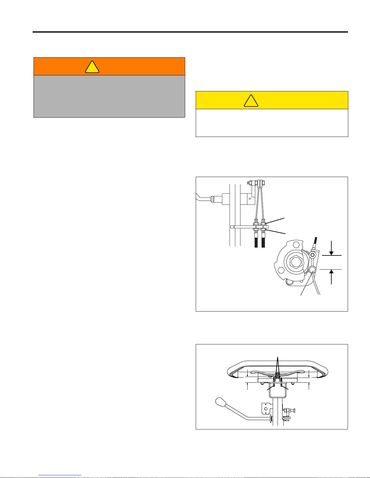
AYARLAR (TÜM ÜNITELER) 6
!
!
TUTAMAÇ
A
B
C
38 mm
FREN BANDI
27 mm 22 mm
X
Y
Z
6 AYARLAR (TÜM ÜNITELER)
6.1 GENEL____________ __________________________________________ ___ __ __ ______
2. Yıpranmış veya hasarlı bileşenleri değiştirin,
UYARI
Bu ekipmanı temizlemeden, ayarlamadan veya
onarmadan önce ciddi yaralanm aları engell emek için
her zaman tüm döndürme mekanizmalarını devre dışı
bırakın, el frenini çekin, çim anahtarını kapatın ve güç
konektörünün bağlantısını kesin.
1. Ayar ve bakım işlemleri her zaman yetkili teknik
görevli tarafından gerçekleştirilmelidir. Ayar doğru
olarak yapılamıyorsa, yetkili Jacobsen Satıcınıza
başvurun.
6.2 FREN____________________________________________________________________
Doğru ayarlanmış fren, çekilebilmesi için fren kolunun
üstünde 4,5 kg çekme gücü gerektirir ve boşa alındığında
ortaya getirilmesi için 38 mm merkez gerektirir.
ayarlamayın.
3. Gevşek giysiler, takı veya uzun saç, hareketli
parçalara takılabilir.
DİKKAT
Makinenin hareketli ve sabi bileşenleri arasına
ellerinizi ve parmaklarınızı kaptırmamak için dikkatli
olun.
4. Hız sınırı ayarlarını değiştirmeyin veya döndürme
mekanizması motorlarını fazla hızlandırmayın.
1. Küçük ayarlar tutamaçta gerçekleştirilir. Somunu (A)
gevşetin, fren kablosunu ayarlamak için somunu
çevirin (B) ve ardından somunu sıkın (A).
2. Ayarlar tutamaçta yapılamıyorsa, taşıma tekerleğini
çıkarın ve ayarı fren bantında gerçekleştirin.
3. Vidayı gevşetin (C) v e istenilen fren gerginliğini elde
etmek için kabloyu çekin. Vidayı sıkın (C). (A) ve
(B)'yi yeniden ayarlayın.
Sekil 6A
6.3 HIZ KOLU DURAKLARI _______ ______________________________________________
1. Her iki somunu da (X) gevşetin.
2. Pozitif kol durağını (Y) 22 mm olarak ayarlayın.
3. Negatif kol durağını (Z) 27 mm olarak ayarlayın.
4. Ayarı sabitlemek için somunları (X) sıkın.
Kol duraklarını ayarladıktan sonra, kontrollerin hız kolu
kalibrasyonu sıfırlanmalıdır. [Bkz. Bölüm 4.3]
Sekil 6B
tr-31

6 AYARLAR (TÜM ÜNITELER)
F
E
D
!
6.4 TUTAMAÇ________________________________________________________________
1. Tutamaç çubuğunun (F) açısını ayarlamak için çim
biçme makinesinin her iki tarafındaki vidayı (D)
gevşetin ve tutamaç çubuğunu istediğiniz konuma
ayarlayın.
2. Tutamaç çubuğunu ayarladıktan sonra, tutamaç
çubuğunun dirsekteki yuvanın alt kısmında
oturmasını sağlamak için dirseği (E) ayarlayın.
Vidayı sıkın (D).
Sekil 6C
6.5 DÖNDÜRME MEKANIZMASI KAYIŞLARI ______________________________________
.
DİKKAT
Kayışta kalıcı hasarı engellemek için, kayışı
bükmeyin, katlamayın, kıvırmayın veya fazla
sıkmayın.
1. Kayışı (G) ayarla mak için 5/ 16-18 x 1” onal tılık kafal ı
vidayı (K) ve 5/16-18 onalt ılık somunu (L) bağlama
dirseğinin (H) altına takın. Somunları (J) gev şetin.
2. Yassı bıçak ayar çubuğunu (M) silindirin üstün ve
vidanın altına (K) yerleştirin. Kayış (G), orta kirişe
0,45 ~ 0,91 kg yük uygulanmış biçimde 2,5 mm
dönene kadar vidayı (K) sıkın.
3. Somunları (J) sıkın ve 5/16-18 x 1” vidayı (K)
çıkarın ve somunu (L) indirin.
4. Daha sonra ayarlamak üzere donanımı (K ve L)
güvenli bir yere yerleştirin.
5. Kayışı ayarlamak (N) için mil donanımını (P) ve mil
motoru yuvasını, kayış orta kir işe 0,45 ~ 0,9 1 kg yük
uygulanmış biçimde 2,5 mm dönene kadar çim
biçme makinesinin ö nüne doğru gevşetin. Donanımı
sıkın (P).
L
M
J
P
P
J
H
K
N
J
G
J
P
tr-32
Sabit Kafalı Çim Biçme Makinesi Ayarları
Hareketli Kafalı Çim Biçme Makinesi Ayarları
Sekil 6D

AYARLAR (TÜM ÜNITELER) 6
!
U
R
V
S
W
Pil Gücü Modülü
Jeneratör Seti Güç Modülü
T
6.6 ÖN SILINDIR AĞIRLIĞI _____________________________________________________
Ön silindirin ağırlığı ayarlanabilir. Çim gereksinimlerine
uygun olarak ön silindir ağırlığını ayarlayın.
DİKKAT
Yaralanmayı veya mala zarar gelmesini engellemek
için pil paketini çıkarmadan önce çim biçme
makinesini destek çubuğunun üzerine yerleştirin.
Eksiksiz pil paketlerinin ağırlığı yaklaşık 25 kg'dir.
Bunları taşırken uygun kaldırma teknikleri kullanın.
1. Pil Gücü Modülü: Ön silindir ağırlığını ayarlamak
için güç konektörünün (R) bağlantısını kesin ve pil
paketini (S) çıkarın. Donanımı (T) gevşetin, pil
paketini çim biçme makinesine tekrar yerleştirin, çim
biçme makinesini destek çubuğundan indirin ve pil
montaj tablasını (U) gerektiği kadar kaydırın.
Jeneratör Seti Güç Modülü: Motor montaj
donanımını (V) gevşetin ve motoro gerektiği (W)
kadar kaydırın.
2. Ön silindir ağırlığını ayarlamak için:
a. Ön silindir ağırlığını artırmak için pil tabl asını (U)
veya motoru (W) çim biçme mak inesinin önüne
doğru kaydırın.
b. Ön silindir ağırlığını azaltmak için pil tablasını (U)
veya motoru (W) çim biçme makinesinin
arkasına doğru kaydırın.
c. Ön silindir ağırlığını ayarlamak için güç modülü
çerçevesinin üzerindeki yapıştırmayı kılavuz
olarak kullanın. Yağ oluğunu (Jeneratör Seti)
veya pil tablasındaki (Pil Tablası) V çentiğini
çıkartma üzerindeki istenen çizgiyle hizalama,
uygun ön silindir ağırlığı ayarına olanak sa
3. Pil Gücü Modülü: Istenen ağırlık sağlandığında,
güç modülü çerçevesinin kenarı ile tabla (U)
arasındaki mesafeyi ölçün. Pil paketini (S) çıkarın.
Ölçülen boyutları yeniden denetleyin ve donanımı
(R) sıkın.
Jeneratör Seti Güç Modülü: Motor montaj
donanımını sıkın (V).
ğlar.
Sekil 6E
tr-33

6 AYARLAR (TÜM ÜNITELER)
4.6
8.8
10.9
12.9
6.7 TORK ÖZELLIKLERI _________________ ___ __ _______________________ __________
BİLGİ
Bu çizelgelerdeki tüm tork değerleri ya klaşık değerlerd ir ve sadece başv urur içindr. Bu tork değerlerini ku llanmak
sadece sizin riskinizdir. Jacobsen bu çizelgelerin kullanılmasından kaynaklanan herhangi bir kayıp, hak veya
hasardan sorumlu değildir. Herhangi bir tork değerini kullanırken her zaman çok dikkat edilmelidir.
Jacobsen aksi belirtilmedikçe standart olarak Derece 5 Kaplamalı somunlar kullanmaktadır. Kaplamalı somunları
sıkıştırırken yağlanmış için verilen değeri kullanın.
AMERİKAN ULUSAL STANDART PERÇİNLER
BİRİM-
BOYUT
#6-32 in-lb (Nm) – 20 (2.3) – – 7/16-14 ft-lb (Nm) 37 (50.1) 50 (67.8) 53 (71.8) 70 (94.9)
#8-32 in-lb (Nm) – 24 (2.7) – 30 (3.4) 7/16-20 ft-lb (Nm) 42 (56.9) 55 (74.6) 59 (80.0) 78 (105)
#10-24 in-lb (Nm) – 35 (4.0) – 45 (5.1) 1/2-13 ft-lb (Nm) 57 (77.2) 75 (101) 80 (108) 107 (145)
#10-32 in-lb (Nm) – 40 (4.5) – 50 (5.7) 1/2-20 ft-lb (Nm) 64 (86.7) 85 (115) 90 (122) 120 (162)
#12-24 in-lb (Nm) – 50 (5.7) – 65 (7.3) 9/16-12 ft-lb (Nm) 82 (111) 109 (148) 115 (156) 154 (209)
1/4-20 in-lb (Nm) 75 (8.4) 100 (11.3) 107 (12.1) 143 (16.1) 9/16-18 ft-lb (Nm) 92 (124) 122 (165) 129 (174) 172 (233)
1/4-28 in-lb (Nm) 85 (9.6) 115 (13.0) 120 (13.5) 163 (18.4) 5/8-11 ft-lb (Nm) 113 (153) 151 (204) 159 (215) 211 (286)
5/16-18 in-lb (Nm) 157 (17.7) 210 (23.7) 220 (24.8) 305 (34.4) 5/8-18 ft-lb (Nm) 128 (173) 170 (230) 180 (244) 240 (325)
5/16-24 in-lb (Nm) 173 (19.5) 230 (26.0) 245 (27.6) 325 (36.7) 3/4-10 ft-lb (Nm) 200 (271) 266 (360) 282 (382) 376 (509)
3/8-16 ft-lb (Nm) 23 (31.1) 31 (42.0) 32 (43.3) 44 (59.6) 3/4-16 ft-lb (Nm) 223 (302) 298 404 315 (427) 420 (569)
3/8-24 ft-lb (Nm) 26 (35.2) 35 (47.4) 37 (50.1) 50 (67.8) 7/8-14 ft-lb (Nm) 355 (481) 473 (641) 500 (678) 668 (905)
LER
DERECE 5 DERECE 8 BOYUT
Yağlanmış Kuru Yağlanmış Kuru Yağlanmış Kuru Yağlanmış Kuru
BİRİM-
LER
DERECE 5 DERECE 8
METRİK PERÇİNLER
Aliminyuma
Yapılan
Önemli
BOYUT
BİRİM-
LER
Yağlanmış Kuru Yağlanmış Kuru Yağlanmış Kuru Yağlanmış Kuru
Olmayan
Perçinler
M4 Nm (in-lb) – – – – – – 3.83 (34) 5.11 (45) 2.0 (18)
M5 Nm (in-lb) 1.80 (16) 2.40 (21) 4.63 (41) 6.18 (54) 6.63 (59) 8.84 (78) 7.75 (68) 10.3 (910 4.0 (35)
M6 Nm (in-lb) 3.05 (27) 4.07 (36) 7.87 (69) 10.5 (93) 11.3 (102) 15.0 (133) 13.2 (117) 17.6 (156) 6.8 (60)
M8 Nm (in-lb) 7.41 (65) 9.98 (88) 19.1 (69) 25.5 (226) 27.3 (241) 36.5 (323) 32.0 (283) 42.6 (377) 17.0 (150)
M10 Nm (ft-lb) 14.7 (11) 19.6 (14) 37.8 (29) 50.5 (37) 54.1 (40) 72.2 (53) 63.3 (46) 84.4 (62) 33.9 (25)
M12 Nm (ft-lb) 25.6 (19) 34.1 (25) 66.0 (48) 88.0 (65) 94.5 (70) 125 (92) 110 (81) 147 (108) 61.0 (45)
M14 Nm (ft-lb) 40.8 (30) 54.3 (40) 105 (77) 140 (103) 150 (110) 200 (147) 175 (129) 234 (172) 94.9 (70)
tr-34

SABIT KAFALI BOBIN AYARLARI 7
!
!
!
°
°
0,8 mm
7 SABIT KAFALI BOBIN AYARLARI
7.1 GENEL____________ __________________________________________ ___ __ __ ______
2. Yıpranmış veya hasarlı bileşenleri değiştirin,
UYARI
Bu ekipmanı temizlemeden, ayarlamadan veya
onarmadan önce ciddi yaralanm aları engell emek için
her zaman tüm döndürme mekanizmalarını devre dışı
bırakın, el frenini çekin, çim anahtarını kapatın ve güç
konektörünün bağlantısını kesin.
1. Ayar ve bakım işlemleri her zaman yetkili teknik
görevli tarafından gerçekleştirilmelidir. Ayar doğru
olarak yapılamıyorsa, yetkili Jacobsen Satıcınıza
başvurun.
ayarlamayın.
3. Gevşek giysiler, takı veya uzun saç, hareketli
parçalara takılabilir.
DİKKAT
Makinenin hareketli ve sabi bileşenleri arasına
ellerinizi ve parmaklarınızı kaptırmamak için dikkatli
olun.
4. Hız sınırı ayarlarını değiştirmeyin veya döndürme
mekanizması motorlarını fazla hızlandırmayın.
7.2 SILINDIRDEN YASSI BIÇAĞA________________________________________________
(Ön Ayar Kontrolü)
1. Uçtaki oynama veya radyal oynama için silindir
bağlantılarını kontrol edin. Silindirde yukarıdan
aşağıya veya iki taraf ar asında herhangi bir anormal
hareket varsa, gereken bileşenleri ayarlayın veya
değiştirin.
6. Çim koşulları da ayarı ekleyecektir.
a. Kuru ve aralıklı k oşullar, ısı oluşmasını ve silindir
ile yassı bıçağa zara r gelmesini engelleme k için
daha geniş aralık gerektir ecek ti r.
b. İyi bir neme sahip yüksek kaliteli çim daha yakın
aralık (sıfıra yakın) gerektirir.
DİKKAT
Kişisel yaralanmaları veya keskin kenarlara zarar
vermeyi engellemek için silindiri çok dikkatle tutun.
2. Kıvrılma veya çentiklenmenin olmadığı iyi
durumdaki keskin kenarların bulunduğundan emin
olmak için silindir bıçaklarını ve yassı bıçağı
inceleyin.
a. Silindir bıçakların ve yassı bıçağın keskin
kenarlarının keskin, çapaksız olması ve
yassılaşmamış olduğundan emin olun.
b. Yassı bıçak ve yassı bıçak arkası tam olarak
sıkılaştırılmış olmalıdır. Yassı bıçak düz ve
keskin olmalıdır.
c. Yassı bıçağın ön yüzünde en az 0,8 mm düz
yüzey korunmalıdır. Yassı bıçak kılıfı için
standart düz kılıf kullanın.
3. Silindir veya yassı bıçak döndürerek cilalama
işlemiyle düzeltilemeyecek kadar yıpranmış veya
hasar görmüşse, yeniden bileylenmelidir.
4. Doğru silindirden yassı bıçağa ayarı önemlidir.
Silindir ile yassı bıçak boyunca 0,0 25 ila 0,076 mm
arasında bir boşluk ko runmalıdır.
5. Silindir yassı bıçağa paralel olmalıdır. Doğru
ayarlanmamış silindir, zamanından önce keskin
kenarlarını kaybedecek ve silindir ile yassı bıçakta
ciddi hasarla sonuçlanabilecektir.
Sekil 7A
tr-35

7 SABIT KAFALI BOBIN AYARLARI
!
Dönüş
Ön Kenar
A
B
C
D
E
F
G
H
7.3 YASSI BIÇAK AYARI _______________________________________________________
1. Yassı bıçak üzerindeki yaylanma yükünü artırmak
veya azaltmak için ayarlayıcı (A) kullanılır. Yassı
bıçağı silindire doğru veya silindirden uzağa
ilerletmek için ayarlayıcı (B) kullanılır.
2. Bİrçok ayarın ardından yay tam olarak
toplandığında, yassı bıçak hareket etmemelidir.
(A)'yi ayarlamadan önce (B)'yı geri çekin.
3. Birçok uygulama için yayı 25 mm sıkıştırın.
4. Ayara, silindiri ön ucundan ayarlamaya başlayın ve
arka uca ilerleyin. Silindir bıçağının ön ucu, normal
dönüş sırasında yassı bıçağın üzerinden geçen
uçtur.
DİKKAT
Kişisel yaralanmaları veya keskin kenarlara zarar
vermeyi engellemek için silindiri çok dikkatle tutun.
5. Yassı bıçağı silindire doğru yaklaştırmak için
ayarlayıcıyı (B) saat yönünde, silindirden uzağa
ilerletmek için saat yönünün tersine döndürün.
a. Boşluk ölçeğini veya şim malzemesini silindir
bıçağıyla yassı bıçak arasında 0,025 –
0,075 mm kaydırın. Silindiri döndürmeyin.
b. Silindirin arka ucunu da aynı biçimde ayarlayın
ve ardından arka uçtaki ayarı tekrar kontrol edin.
c. Silindir ve yassı bıçak doğru olarak
ayarlandığında, silindir serbestçe dönecek ve
gazete yassı bıçağa 90? açıyla tutulduğunda,
silindirin tam uzunluğu kadar gazeteyi kesecektir.
Sekil 7B
Sekil 7C
7.4 KESME YÜKSEKLIĞI_______________________________________________________
Not: Kesme yüksekliğini ayarlamadan önce yassı
bıçağın doğru ayarlandığından emin olun. (Bkzç Bölüm
7.3)
1. Destek çubuğunu aşağı doğru itin ve çim biçme
makinesini tutamacından geriye doğru eğin.
5. Vida kafasını yassı bıçağın (H) üzerine kaydırın ve
silindirler ayar çubuğuna hafifçe temas edecek
biçimde topuzu (C) ayarlayın. Somunu sıkın (D).
6. Silindirin diğer ucunda Adım 4 ve 5'i yineleyin,
ardından somunları (D) sıkın. Gerekiyorsa, kesim
yüksekliğini yeniden denetleyin ve ayarlayın.
BİLGİ
Jeneratör Seti Güç Modülleri: Çim biçme makinesini
uzun süre geriye yatmış biçimde bırakmayın, aksi
halde yağ yanma odasına sızabilir.
2. Her iki taraftaki somunla rı (D), topuz (C) ön silindirin
kalkmasına izin verecek kadar gevşetin. Her iki
tarafı da eşit oranda kaldırın.
3. Ayar vidasını (G) istenilen kesme yüksekliğine (F)
ayarlayın. Ayar çu buğu (E) ile vida kafasının (G) alt
tarafı arasındaki mesafeyi ölçün, ardından ayarı
sabitlemek için kanatlı somunu sıkın.
4. Ayar çubuğunu ön silindir ile dönme mekanizması
arasına, silindirlerin dış ucuna yakın biçimde
yerleştirin.
Sekil 7D
tr-36

HAREKETLI KAFALI BOBIN AYARLARI 8
!
!
!
°
°
0,8 mm
Ön Kenar
LF025
8 HAREKETLI KAFALI BOBIN AYARLARI
8.1 GENEL____________ __________________________________________ ___ __ __ ______
2. Yıpranmış veya hasarlı bileşenleri değiştirin,
UYARI
Bu ekipmanı temizlemeden, ayarlamadan veya
onarmadan önce ciddi yaralanm aları engell emek için
her zaman tüm döndürme mekanizmalarını devre dışı
bırakın, el frenini çekin, çim anahtarını kapatın ve güç
konektörünün bağlantısını kesin.
1. Ayar ve bakım işlemleri her zaman yetkili teknik
görevli tarafından gerçekleştirilmelidir. Ayar doğru
olarak yapılamıyorsa, yetkili Jacobsen Satıcınıza
başvurun.
8.2 YASSI BIÇAKTAN SILINDIRE ________________________________________________
(Ön Ayar Kontrolü)
ayarlamayın.
3. Gevşek giysiler, takı veya uzun saç, hareketli
parçalara takılabilir.
DİKKAT
Makinenin hareketli ve sabi bileşenleri arasına
ellerinizi ve parmaklarınızı kaptırmamak için dikkatli
olun.
4. Hız sınırı ayarlarını değiştirmeyin veya döndürme
mekanizması motorlarını fazla hızlandırmayın.
1. Uçtaki oynama veya radyal oynama için silindir
bağlantılarını kontrol ed in. Uçta oynama v eya radyal
oynama olmamalıdır. Bkz. Bölüm 8.5
DİKKAT
Kişisel yaralanmaları veya keskin kenarlara zarar
vermeyi engellemek için eldiven giyin ve silindir ile
yassı bıçağı çok dikkatle tutun.
2. Kıvrılma veya çentiklenmenin olmadığı iyi
durumdaki keskin kenarların bulunduğundan emin
olmak için silindir bıçaklarını ve yassı bıçağı
inceleyin.
a. Silindir b ıçakların ve yassı bıçağın ön kenarının
keskin, çapaksız olması ve yassılaşmamış
olduğundan emin olun.
b. Yassı bıçak ve yassı bıçak arkası tam olarak
sıkılaştırılmış olmalıdır. Yassı bıçak düz ve
keskin olmalıdır.
c. Yassı bıçağın ön yüzünde en az 0,8 mm düz
yüzey korunmalıdır. Yassı bıçak kılıfı için
standart düz kılıf kullanın.
kenarlarını kaybedecek ve silindir ile yassı bıçakta
ciddi hasarla sonuçlanabilecektir.
6. Çim koşulları da ayarı ekleyecektir.
a. Kuru ve aralıklı k oşullar, ısı oluşmasını ve silindir
ile yassı bıçağa zara r gelmesini engelleme k için
daha geniş aralık gerektir ecek ti r.
b. İyi bir neme sahip yüksek kaliteli çim daha yakın
aralık (sıfıra yakın) gerektirir.
Sekil 8A
3. Silindir veya yassı bıçak döndürerek cilalama
işlemiyle düzeltilemeyecek kadar yıpranmış veya
hasar görmüşse, yeniden bileylenmelidir.
4. Doğru silindirden yassı bıçağa ayarı önemlidir.
Silindir ile yassı bıçak boyunca 0,0 25 ila 0,076 mm
arasında bir boşluk ko runmalıdır.
5. Silindir yassı bıçağa paralel olmalıdır. Doğru
ayarlanmamış silindir, zamanından önce keskin
Sekil 8B
tr-37
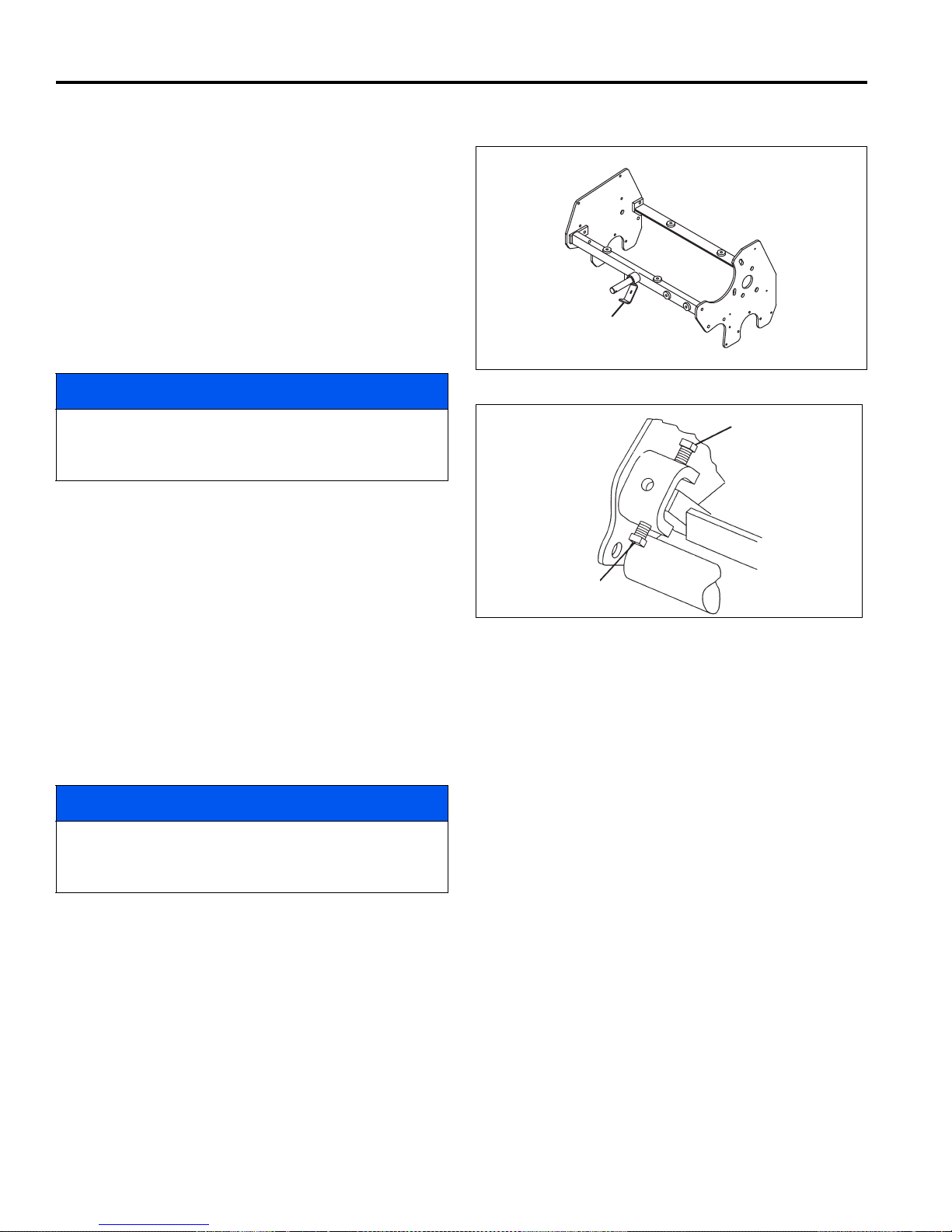
8 HAREKETLI KAFALI BOBIN AYARLARI
GKV-1
B
C
8.3 YASSI BIÇAK AYARI _______________________________________________________
1. Ayarı yapmadan önce Bölüm 8.2'yi okuyun.
2. Ayara, silindiri ön ucundan ayarlamaya başlayın ve
arka uca ilerleyin. Silindir bıçaklarının ön ucu,
silindirin normal dönüşü sırasında yassı bıçağın
üzerinden geçen uçtur.
3. Yassı bıçak ayarlama donanımına (B ve C) daha
fazla erişim, çim biçm e makinesi tutamacından geri
yatırılmışken sınır dirseğini (A) silindirden uzağa
doğru bastırarak elde edilebilir. Bu, silindirin arka
tarafının aşağı inmesine ve çerçeveden
uzaklaşmasına olanak sağlar.
A
BİLGİ
Jeneratör Seti Güç Modülleri: Çim biçme makinesini
uzun süre geriye yatmış biçimde bırakmayın, aksi
halde yağ yanma odasına sızabilir.
4. Aralığı ayarlamak için ayarlayıcıları (B ve C)
kullanın. Alt ayarlayıcıyı (C) gevşetin ve aralığı
kapatmak için üst ayar layıcıyı (B) aşağı doğru (saat
yönünde) döndürün.
a. Boşluk ölçeğini veya şim malzemesini silindir
bıçağıyla yassı bıçak arasında 0,025 – 0,075 mm
kaydırın. Silindiri döndürmeyin.
b. Silindirin arka ucunu da aynı biçimde ayarlayın
ve ardından arka uçtaki ayarı tekrar kontrol
edin.
c. Silindir yassı bıçakla doğru olarak
ayarlandığında, silindir serbestçe dönecek ve
gazete yassı bıçağa 90? açıyla tutulduğunda,
silindirin tam uzunluğu kadar gazeteyi
kesebileceksiniz.
BİLGİ
Sekil 8C
Sekil 8D
Fazla sıkılaştırmadan kaçının aksi halde yassı bıçakta
ve silindir bıçaklarında hasar oluşabilir. Silindirler
serbestçe dönmelidir.
4. Çim biçme makinesini yukarı konumuna döndürün.
Sınır dirseği (A) yaylıdır ve silindir üzerindeki
dirseğe mandallanmalıdır.
tr-38

HAREKETLI KAFALI BOBIN AYARLARI 8
F
K
G
E
H
J
P
P
45 mm
8.4 KESME YÜKSEKLIĞI_______________________________________________________
Not: Kesme yüksekliğini ayarlamadan önce her zaman
silindirden yassı bıçağa olan ayarı yapın. (Bölümler 8.2 ve
8.3).
1. Destek çubuğunu aşağı doğru itin ve çim biçme
makinesini tutamacından geriye doğru eğin.
BİLGİ
Jeneratör Seti Güç Modülleri: Çim biçme makinesini
uzun süre geriye yatmış biçimde bırakmayın, aksi halde
yağ yanma odasına sızabilir.
1. Ayar çubuğunda (E) istenilen kesme yüksekliğini
ayarlayın.
a. Vida kafasının alt tarafı ile ayar bloğu yüzeyi (F)
arasındaki mesafeyi ölçün.
b. İstenilen yüksekliği elde etmek için vidayı (H)
ayarlayın ve ardından kanatlı somunu sıkın.
2. Ön silindir dirsekleri (G) üzerindeki somunları, ayar
topuzu (K) ön silindiri kaldıracak veya indirecek kadar
gevşetin.
3. Ayar kolunu (E) bir silindir ucunun yakınına, önveya
arka silindirlerin altına yerleştirin.
4. Ayar vidasını (H) yassı bıçağın (L) üzerine kaydırın ve
vida kafasıyla yassı bıçak arasındaki aralığı kapatmak
için topu zu (K) ayarlayın. Ardından emniyet somununu
(G) sıkın.
5. Diğer uçta Adım 4 ve 5'i yineleyin Diğer ucu
ayarlamadan önce bir uçtaki ayarı tamamlayın.
6. Somunları (G) sıkın ve her ucu yeniden kontrol edin.
Sekil 8E
8.5 SILINDIR BAĞLANTISI______________________________________________________
Uçta oynama veya radyal oynama, kötü bağlantıları, zayıf
gerilimli yayı veya geriye çekilmiş somunu belirtir.
1. Bağlama yuvası montaj donanımını kontrol edin.
Bileşenleri gerektiği gibi sıkılaştırın veya değiştirin. Yağ
gidericiyle telleri dikkatle temizleyin.
2. Somuna (P) orta güçte Loctite uygulayın, ardından
somun, silindir şaftının ucundan 46 mm uzak olana
kadar somunu silindir şaftına geçirin.
3. Yayı ayarladıktan sonra NLGI - Grade O yağ ile silindir
bağlantısı yuvalarını doldurun.
8.6 SILINDIR TAKIMININ ÇIKARILMASI ___________________________________________
Silindir takımı, bakım veya farklı bir silindirde kullanılmak
üzere çıkarılabilir.
1. İnce mili ve rondelayı çıkarın ve kaldırma çengellerini
millerden kaydırın.
2. Motor elektrikli konektörlerinin ve silindir topraklama
kablosunun bağlantısını kesin. Kasnak motorları
mekanizmadan söküldüğü zaman motorun içine pislik
girmemesi için motor üzerindeki bağlantıları örterek
koruyun.
3. İnce mili ve düz rondelayı çıkarın ve panhart çubuğunu
silindir sürgüsünden kaldırın.
Jeneratör Seti Güç Modülleri: Çim biçme makinesini
uzun süre geriye yatmış biçimde bırakmayın, aksi halde
yağ yanma odasına sızabilir.
4. Üniteyi tutamacın üstüne arkaya doğru yatırın ve
silindiri çim biçme makinesinden uzağa doğru kaydırın.
5. Kasnak montajı söküm işleminin tersidir. Motor
bağlantılarını sadece elle sıkın, motor bağlantılarını
sıkmak için anahtar kullanmayın.
BİLGİ
Sekil 8F
tr-39

9 PIL GÜCÜ MODÜLÜ
!
TR016
!
TR017
9 PIL GÜCÜ MODÜLÜ
9.1 GÜVENLIK _______________________________________ ___ __ __ ___ ______________
Piller, ciddi yanıklarla sonuçlanabile ce k sey r eltil miş sülfürik asit içerir.
Şarj olma döngüsü sırasında pil içinde hidrojen gazı oluşur. %4 veya daha yüksek hidrojen konsantrasyonu patlayıcıdır
ve çıplak alev veya elektrik kıvılcımıyla tutuşabilir. Pil patlaması, sülfürik aside neden olur ve pil parçaları kuvvetli
biçimde etrafa fırlayabilir.
Pillerle çalışırken veya pillerin yakınındayken her zaman aşağıdaki uyarılara dikkat edin:
UYARI
Pil içindeki elektrolit seyreltilmiş
asittir ve deri ile gözlerde ciddi
yanıklara neden ol abilir. Vücuda ve
gözlere gelen elektrolit serpintilerini
bol miktarda t emiz su ile temizleyin.
Hemen bir doktora başvurun. Pilleri
şarj ederken her zaman güvenlik
siperi veya onaylı güvenlik gözlükleri takı n.
%4'ten düşük konsantrasyonlu hidrojen patlayıcıdır ve
elektrikli çim biçme makinelerinin şarj döngüsü
sırasında oluşurlar. Havadan hafif olduklarından
binaların tavanlarında toplanır, bu da iyi
havalandırmayı g erektir ir. Saatte 5 kez hava değişimi,
minimum gereklilik olarak kabul edilir.
Pillerin çevresinde sigara içmeyin.
Çıplak alev veya el ektrik arkı ol uşturabile cek elektrik li
ekipman yanında pilleri şarj etmeyin.
Araç üzerinde çalışmadan önce kontak anahtarının
kapaıl olduğundan, tüm elektrikli aksesuarl arın kapalı
ve güç konektörün ün b a ğlantı sın ın kes ildiğinden emin
olun.
UYARI
Patlama veya ciddi ki şisel yaralanmayla
sonuçlanabilecek, düşen anahtar
takımının pillerin kısa devre yapması
olasılığını engellemek için anahtar
takımlarını vinil bantla sarın.
Elektrolit serpintileri, 5,7 litre suda
çözülmüş 59,1 ml karbonat ile nötraliz e
edilmeli ve suyla yıkanmalıdır.
Pil terminalinde yük varken kesinlikle devreyi
kesmeyin.
Piillerle çalışırken uygun koruyucu giysiler giyin.
Elektrolit gözlerde, d e ride ve giy si le rde c idd i y anı kl ar a
neden olabilir.
Eksiksiz pil paketlerinin ağırlığı yakla
Bunları taşırken uygun kaldırma teknikleri kullanın.
Piller, pil uçları, terminaller ve il gili aksesu arlar kur şun
içerir ve kurşun ve kurşun bileşenleri Kaliforniya
Eyaletinde kanser ile üreme sağlığı hasarlarına neden
olarak kabul edilir. Işlemden sonra ellerinizi yıkayın
şık 25 kg'dir.
.
Tüm takıları çıkarın (saatler, yüzük vs).
9.2 GENEL __________________________________________________________________
Bu çim biçme m aki ne si nde k ull anı lan pi ll er, kolay bak ıml ı
mühürlü kurşun asit (SLA) türüdür.
Pil üzerinde testler uygularken ısı önemlidir ve test
sonuçları sıcaklık farklarını telafi etmek üzere
düzeltilmelidir.
Pil yaşlandıkça, kapasitesi düşmesine rağmen yeterli
performansa sahip olmaya devam eder. Kapasite, tam
şarj edilmiş durumdayken üretildiği amperi sağlamaya
devam edebileceği süreyi tanımlar.
tr-40
Yeni bir pil, maksimum kapasitesine er işmeden önce iyi
tasarlanmalıdır. Pilin maksimum ömrü var dır bu nedenle ,
mevcut ömrü en fazla seviyeye getirmek ve plin ömrünü
kısaltabilecek faktörleri azaltmak için iyibir bakım
yapılmalıdır.

PIL GÜCÜ MODÜLÜ 9
5,7 LİTRE
TEMİZ SU
59,1 ML SODYUM
BİKARBONAT
(KARBONAT)
7,6 LİTRE BAHÇE
PÜSKÜRTECİ 5,7 LİTRE SU
METAL OLMAYAN
ÇUBUK
TR008
9.3 BAKIM ___________________________________________________________________
Araç Listesi
Yalıtılmış anahtar, 3/8”
Yalıtılmış anahtar, 11/32”
Standart Tornavida
Pilleri şarj etmeden önce
Pil şarj cihasının konektör yuvalarını ve pil paketini kir
veya atık olup olmadığını görmek için inceleyin.
Korozyonu engellemek için her iki terminale de beyaz
lityum yap uygulamak önerilir.
Kullanımın ardından pilleri günlük olarak şarj edin.
9.4 PILLERI TEMIZLEME _______________________________________________________
Pilleri temizlerken, asit kalıntılarını nötralize etmek için
karbonat çözeltisi ve su püskürtmeden su hortumu
kullanmayın.
Asiti nötralize et med en su hor tum u kul la nma , asi ti pil leri n
üstünden, metal yapılara veya çimento/asfalt tabana
yapışabileceği çim biçme makinesinin veya depolama
alanının diğer alanlarına taşıyacaktır. Pilleri hortumla
temizledikten sonra, iletken olan ve pillerin
boşaltılmasına katkıda bulunan kalıntı piller üzerinde
kalacaktır.
Doğru temizleme tekniği, karbonat ve su solüsyonuyla
pillerin üstünü ve yanlarını spreylemektir. Bu solüsyon,
metalik sprey çubuğu olmayan bahçe türü spreyle en
iyi uygulanır. Solüsyon, 5,7 litre temiz suda çözülmüş
59,1 ml karbonattan oluşmalıdır. Pillere ek olarak,
karbonatlı solüs yonla spreylenebilecek pillerin yanındaki
metal bileşenlere de dikkat edilmelidir.
Solüsyonun en az 3 dak ika boyunca n üfuz etmesine iz in
verin; pillerin kendiliğinden boşalmasına neden
olabilecek kalıntıları gidermek üzere pillerin üzerini
süpürmek için k alın ve yumuşak fırç a veya bez kullanın.
Düşük basınçlı temiz suyla tüm alanı temizleyin.
Temizleme yılda bir kez veya aşırı koşullarda daha sık
olarak yapılmalıdır.
Sekil 9A
tr-41

9 PIL GÜCÜ MODÜLÜ
!
!
WARNING - For continued protection
against fire, replace only with same
size and type fuse.
INTERACTER INCORPORATED
MODEL:
BATCH: SERIAL NO:
INPUT:
1. Connect and disconnect battery leads only when
supply cord is disconnected or arcing and burning
may result.
2. BATTERY LEAD CONNECTIONS - For a battery
installed in a vehicle, first connect charger output
lead to ungrounded battery post - not connected to
automobile chassis - in accordance with polarity
indication, and then opposite polarity lead to
chassis away from battery; do not connect to
carburetor or fuel lines. Disconnect chassis lead
first. For battery not installed in a vehicle, refer to
instruction manual.
3. Do not over-charge battery - see instruction
manual
4. Do not smoke, strike a match, or cause a spark in
vicinity of battery during charging.
5. Use only in a well ventilated area.
This equipment employs parts, such as switches and
relays, that tend to produce arcs and sparks and
therefore, if used in a garage, locate in a room or
enclosure provided for the purpose or not less than 18
inches from the floor.
CAUTION
- DO NOT EXPOSE TO RAIN:
replace defective cords or wires immediately.
CAUTION: NE PAS EXPOSER A LA PLUIE.
ADVERTISSEMENT: RISQUE DE MELANGE GAZEAUX
EXPLOSIF. LIRE LA NOTICE AVANT D'UTILISER LE
CHARGEUR.
WARNING - RISK OF EXPLOSIVE GAS MIXTURE
115V
230V
Giri Voltajı Seçici
Konum
1
Konum
2
Yedek Sigorta
Sigorta Tutucu
Sigorta
9.5 PIL ŞARJ CIHAZI ______________________________ __ __ ___ _____________________
Pil şarj cihazı pil paketini tam olarak şarj etmek için
tasarlanmıştır. Doğru çalıştırma yordamı için şarj
cihazıyla birlikte verilen yönerge kılavuzunu okuyun.
Şarj etmeden önce, aşağıdak i lere dik k at edil me li dir :
UYARI
Taşınabilir şarj cihazları toprak üzerindeki platforma
veya şarj ciha zının altında ve çevresinde mak simum
hava akımına izin verecek biçimde platform üzerine
monte edilmelidir. Şarj cihazının yeterli hava akışı
yoksa, şarj ciha zında oluşan ciddi hasar, aşırı ısınma
veya yangın olasılığı ile sonuçlanabilir.
Şarj cihazı, iyi havalandırılmış ve şarj işlemi sırasında
oluşan hidrojen gazını yok edebilecek bir alanda yer
almalıdır. Saatte en az 5 hava değişi mi önerilir.
Şarj konektörü bileşenleri iyi durumda olmalı ve
üzerlerinde kir ile kalıntı bulunmamalıdır. Korozyonu
engellemek için her iki terminale de beyaz lityum yap
uygulamak önerilir.
Şarj cihazı konektörü pil paketi duyuna tam olarak
oturmalıdır.
Şarj cihazı konektörü/kablosu kümesi hasara karşı
korunmuştur ve insanların kablo kümesinin üzerinde
yürümesinden veya takılmasından kaynaklanabilecek
yaralanmaları engelleyecek bir alana yerleştirilmiştir.
Tüm şarj cihazlarını üreticinin yönergelerine uygun
olarak takın.
Şarj cihazı açık alanda çalıştırılıyorsa, yağmura ve
güneşe karşı koruma sağlanmalıdır.
AC Voltajı
Ş
arj cihazının arkasında, giriş voltajı seçme anahtarı
vardır. Bölgenizde kullanılan giriş voltajını belirleyin ve
AC elektrik kabl osunu bağlamadan ö nce anahtarı uygu n
biçimde ayarlayın. Bu şarj cihazı aşağıdaki AC giriş
voltajlarıyla ku lla nıl abi li r :
100 - 130 V (Voltaj seçicisini 115 V (Konum 1) olarak
ayarlar)
200 - 240 V (Voltaj seçicisini 23 0 V (Konum 2) ol arak
ayarlar)
Not: Şarj cihazı 50 veya 60 Hz giriş voltajıyla
çalışacaktır.
AC elektrik kablosunda bö lgenizde kullanılana uygun fiş
olduğundan emin olun. Şarj cihazı topraklama fişine
sahiptir, işlevini iptal etmeyi denemeyin.
UYARI
Topraklanmamış elektrikli cihaz, elektrik şoku veya
elektrik çarpmasıyla sonuçlanabilecek fiziksel tehlike
yaratabilir.
Not: Pil şarj cihazıy la birlikte verilen AC elektrik kablosu
yalnızca 115 V - 60 Hz (Kuzey Amerika) giriş voltajıyla
kullanılır. 115 V - 60 Hz giriş voltajının kullanılmadığı bir
bölgede yaşıyorsanız, yeni AC elektrik kablosunu
bölgenizden satın almanız gerekebilri.
Pil şarj cihazı, 115V AC girişvoltajıyla pil paketini
yaklaşık 5 saa tte tam olar ak şarj etmeli dir. Pil şarj cihazı
süreleri, 100V AC giriş voltajının kullanıldığı bölgelerde
8 saati aşabilir.
Pil şarj cihazını pil paketine bağlamadan veya
çıkarmadan önce AC elektrik kablosunu prizden çıkarın.
Şarj etme (DC) kablosu, pil paketindeki karşılık gelen
duya oturan polarize konektöre sahiptir.
Şarj cihazı doğru çalışmıyorsa, şarj cihazını AC
prizinden ve pil paketinden çıkarın ve sigortayı kontrol
edin. Yeni sigorta gerekiyorsa, Jacobsen Satıcınızdan
4102780 parça numarasıyla sipariş edin. Sigorta
tutucuda yedek bir sigorta vardır.
tr-42
Sekil 9B

PIL GÜCÜ MODÜLÜ 9
!
PN
KEY
Kırmızı Kablo
Siyah Kablo
D
E
E
F
F
Turuncu/Yeşil Kablo
J
K
L
G
F
H
9.6 PILI YERLEŞTIRME ________________________________________________________
Piller temizlendi ve pil tablası alanındaki acid nötralize
edildiyse, çevre bölgelerde korozyon olmamalıdır.
Görülen korozyon h emen mav un spatulas ı ve tel f ırçayla
giderilmelidir. Alan, karbonat ve su solüsyonuyla
yıkanmalı ve astar boya ve korozyana karşı koruyucu
boya uygulamadan önce tamamen kurutulmalıdır.
Piller, Sekil 9C'de gösterildiği biçimde pil tablasına
yerleştirilmelidir. Doğru fiziksel boyuta sahip pilleri
kullanma, hareket etmesini önleyecektir ancak pil
kasasının bozulmasına neden olmayacak kadar sıkı
olmayacaktır.
Tüm kablo ve terminalleri inceleyin. Karbonat ve su
solüsyonu ile pil terminaller i veya kablo t erminallerinden
korozyonu temizleyin ve gerekiyorsa fırçayla temizleyin.
Pil kablolarını bağlam ak için Sekil 9D'de gösteri ldiği gibi
bağlamak için dikkat edin ve pil arkasındaki donanımı
tam olarak sıkılaştırın. Pil terminallerini ve pil kablosu
terminallerini ticari olarak satılan koruyucu kaplamayla
koruyun.
Pil Paketini Değiştirme:
1. Piller i pil tablasına yerleştirin.
2. Vidalar, yaylı rondelalar ve somunlarla sigorta
3. İki kablo bağlama telini (E) ilgili konumlarına
4. Ana kabloyu (F) pil kasası kapağının (G) yanındaki
5. Ana kabloyu (F) pillere ve pil monitörüne (M)
Not: Eclipse çim biçme makinelerinde kullanılmayan
yalıtılmış 15 mm terminalli Turuncu/Yeşil kablo olacaktır.
Kısa devreyi önlemek için kablonun ucunu kapatın.
6. Pil kasasının iki yarısını (G) ve (H) vidalar (J), düz
Pil özellikleri için Bölüm 2.6'e başvurun.
Pil terminali koruyucusu aerosol kapları kullanırken
çok dikkatli olun. Metal kutunun, pil terminalleriyle
temas etmesini (patlamayla sonuçlanabilir)
engellemek için metal kabı yalıtın.
kablosu takımını (D) pil paketine sabitleyin.
sabitleyin.
delikten geçirin.
bağlayın.
rondelalar (K) ve pil kasası şeritleriyle (L) monte
edin.
UYARI
Sekil 9C
Sekil 9D
Sekil 9E
tr-43

9 PIL GÜCÜ MODÜLÜ
!
A
B
C
9.7 PIL PAKETINI DEĞIŞTIRME _________________________________________________
Pil paketi (A) kolayca çıkarılmak ve değiştirilmek üzere
tasarlanmıştır. Bu, piller boşalırsa veya bozulursa, çim
biçme makinesinin hızlıca servise getirilmesine olanak
sağlayacaktır. Ek pil paketleri, aksesuar olarak
bulunabilir. Bkz. Bölüm 2.7
DİKKAT
Yaralanmayı veya mala zarar gelmesini engellemek
için pil paketini çıkarmadan önce çim biçme
makinesini destek çubuğunun üzerine yerleştirin.
Eksiksiz pil paketlerinin ağırlığı yakla
Bunları taşırken uygun kaldırma teknikleri kullanın.
Pil tablasını çıkarmak için:
1. Traktörü düz ve düzgün bir yüzeye park edin.
2. El frenini çekin ve anahtarı kontaktan çıkarın.
3. Pil konektörünün (B) bağlantısını kesin ve çim
biçme makinesini destek çubuğuna yerleştirin.
4. Pil bırakma manda lına (C) bastırın ve aşağıda t utun,
pil paketini (A) çim biçme makinesinden yukarı
kaldırın.
5. Paketi yerle ştirmek için tersine yordam. Pa ketin tam
olarak çerçeveye o turduğundan ve sab it olduğundan
emin olun.
şık 25 kg'dir.
Sekil 9F
tr-44

JENERATÖR SETI GÜÇ MODÜLÜ 10
Üst Yağ Düzeyi
Yağ Dolum Kapağı
10 Jeneratör Seti Güç Modülü
10.1 MOTOR __________________________________________________________________
ÖNEMLİ: Motor üreticisi tarafından hazırlanan Motor
Kılavuzu güç modülüyle birlikte verilmiştir. Motorun
çalışmasını ve bakımını tam olarak öğrenene kadar
motor kılavuzunu dikkatle okuyun. Motor üreticisinin
yönergelerine tam olarak uyma, motorun maksimum
servis ömrünü garantileyecektir. Yedek motor
kılavuzları sipariş vermek için motor üreticisine
başvurun.
Çim biçme makinesi, üreticinin önceden belirlenmiş
ayarlarında en verimli olarak çalışacak ve kesecek
biçimde tasarlanmıştır. Motor üretici ayarlarını
değiştirmeyin veya motoru fazla hızlandırmayın.
Çalıştırma döneminde Jacobsen aşağıdakileri önerilir:
BİLGİ
Yeni motorun doğru açılması, motorun performansıyla
ömrü üzerinde önemli bir fark oluşturacaktır.
1. İlk 25 saat boyunca makineyi fazla zorlamadan
kullanın.
2. Tam yükle çalışmaya başlamadan önce motorun
çalışma ısısına erişmesine izin verin.
3. İlk 20 saat çalışmanın ardından motor yağını
değiştirin.
4. Özel bakım aralıkları için Bölüm 13'ye ve Motor
Kılavuzuna başvurun.
10.2 MOTOR YAĞI _____________________________________________________________
Her günün başlangıcında, motoru çalıştırmadan önce
motor yağını kontrol edin. Yağ düzeyi düşükse, yap
doldurma kapağını çıkarın ve gereken miktarda yağ
ekleyin.
İlk 20 saat çalışm anın ardından ilk motor yağı değişimini
gerçekleştirin. Bunun ardından her 100 saatte bir, yağı
değiştirin.
Ayrıntılı servis bilgileri için motor üreticisinin Sahip
Kılavuzuna bakın.
Yağ ekledikten v eya değişt irdikten sonra motoru ba şlatın
ve 30 saniye boyunca tüm döndürme mekanizmaları
devre dışı durumda, boşta çalıştırın. Motoru durdurun. 30
saniye bekleyin ve yağ düzeyini kontrol edin. Yağ
çubuğunda FULL (Tam) işaretine kadar yağ ekleyin.
Yalnızca API sınıf landırma SG.SF/CC.CD'ye sahip SAE
10W30 motor yağları kullanın.
Sekil 10A
tr-45

10 JENERATÖR SETI GÜÇ MODÜLÜ
!
10.3 MOTOR HIZI ______________________________________________________________
Doğru jeneratör çıktısı için motor hızı fabrikada
ayarlanmıştır. Bununla birlikte motor hızı düzenli olarak
kontrol edilmeli ve 59 volta ayarlanmalıdır. 60 volttan
daha yüksek çıkış voltajı bir alarm sesinin duyulmasın a
neden olacaktır ve siste mde hasarla sonu çlanabili r. Aşırı
voltaj durumu düzeltilmediyse, 60 saniye sonunda
denetleyici makineyi kapatacaktır.
Ayarlar, volt metre kullanılarak motor çalışma
sıcaklığında yapılmalıdır.
1. Motoru durdurun ve jeneratör güç konektörünün
bağlantısını kesin.
2. Kısma kolu kapağını çıkarın.
3. Motoru başlatın ve jeneratör güç konektöründe 59
voltluk çıkış voltajı elde edilene kadar motor kısma
konumunu ayarlayın.
4. Motoru durdurun ve kısma kolu kapağını takın.
5. Güç konektörünü bağlayın.
10.4 BENZIN__________________________________________________________________
Benzinle çalışırken dikkatli olun - çok yanıcıdır.
Onaylı kap kullanın, oluk ağzı benzin doldurma boğazının
içine oturmalıdır. Benzin aktarmak için te neke kutular ve
huni kullanmaktan kaçının.
UYARI
Benzin kapağını benzin deposundan kesinlikle
çıkarmayın veya motor çalışırken ya da motor
sıcakken kesinlikle benzin doldurmayın.
Benzinle çalışırken sigara içmeyin. Kapalı alanda
kesinlikle benzin doldurmayın veya depoyu
boşaltmayın.
Benzini sıçratmayın ve sıçrayan benzini hemen
temizleyin.
Benzin kaplarını hiçbir zaman açık ateş veya kıvılcım
çıkarabilecek ve benzin veya benzin buharını
ateşleyebilecek araçlar yanında kesinlikle kullanmayın
veya saklamayın.
Benzin kapağını y eniden t akıp sıkıştırdığınızdan emin
olun.
• Benzini, yerel veya ülke uygulamalarına ve
yönetmeliklerine ve benzin satıcınızın önerilerine
uygun olarak saklayın.
• Hiçbir zaman depoyu aşırı doldurmayın veya
boşalmasına izin vermey in.
• En az 86 oktan temiz, yeni, normal kurşunsuz benzin
kullanın
• Oksijenle karıştırılmış (karışık) benzin kullanmadan
önce motor kılavuzuna bakın.
• Benzin doldurma boynunun üzerinde doldurmayın.
tr-46

BAKIM 11
!
!
!
11 BAKIM
11.1 GENEL___________________________________________________________________
3. Gevşek giysiler, takı veya uzun saç, hareketli
UYARI
parçalara takılabilir.
Bu ekipmanı temizlemeden, ayarlamadan veya
onarmadan önce ciddi yaralanmaları engellemek için
her zaman tüm döndürme me kani zmala rını dev re dışı
bırakın, el frenini ç ekin, çi m anahta rını ka patın v e güç
konektörünün bağlantısını kesin.
1. Ayar ve bakım işlemleri her zaman yetkili teknik
görevli tarafından gerçek leştirilmelidir. Ayarlar doğru
olarak yapılamıyorsa, Yetkili Jacobsen Satıcınıza
başvurun.
2. Ekipmanı düzenli olarak inceleyin, bakım çizelgesi
oluşturun ve ayrıntılı kayıt tutun.
a. Ekipmanı temiz tutun.
b. Tüm hareketli parçaları düzgün olarak
ayarlanmış ve yağlanmış olarak tutun.
c. Yıpranmış veya hasarlı parçaları makineyi
çalıştırmadan önce değiştirin.
d. Siperleri yerle rinde ve tüm donanımı tam olarak
sabitlenmiş olarak tutun.
e. Tekerlekleri (takılıysa) tam olarak şişirilmiş olarak
tutun.
DİKKAT
Makinenin hareketli ve sabi bileşenleri arasına
ellerinizi ve parmaklarınızı kaptırmamak için dikkatli
olun.
4. Bileşenleri demonte etmek veya yeniden monte
etmek için Parça Kataloğundaki çizimleri referans
olarak kullanın.
5. Zararlı tüm materyali (piller, yağlar vb) yerel ve ülke
yönergelerine uygun olarak geri dönüştürün veya
atın.
6. Hız sınırı ayarlarını değiştirmeyin veya döndürme
mekanizması motorlarını fazla hızlandırmayın.
7. Kasnak ve çekme motoruna bakım ve tamir
yaptıktan sonra motor bağlantılarının sıkıldığını
kontrol edin. Motor bağlantılarını sadece elle
sıkın, motor bağlantılarını sıkmak için anahtar
kullanmayın.
11.2 TEKERLEKLER (SEÇENEK) _________________________________________________
1. Tekerlek ömrünü uzat mak için teker lekler i tam ol arak
şişirilmiş olarak tutun. Basıncı yalnızca tekerlekler
soğukken kontrol edin.
2. Uygun, düşük basınçlı lastik hava basıncı ölçeği
kullanın. 41,3-55,1 kPa.
Doğru eğitiminiz, araçlarınız ve deneyiminiz
olmadıkça, jant üzerindeki tekerleği takmayı
DENEMEYİN. Tekerleği yanlış takmak ciddi
yaralanmayla sonuçlanabilecek patlama oluşturabilir.
DİKKAT
11.3 TEKERLEK BAĞLANTISI____________________________________________________
Bağlantı üzerinde LOCK kel imesi vardır ve yüzeyi ne ok
işareti bulunur. Baplantıyı değiştirirken, bağlantının doğru
yönde ve dönüşte takılı olduğundan kesinlikle emin olun.
Sağ tekerlek için bağlantıyı “LOCK” kilidi, bağlantı
yuvasının Dış tarafında olacak biçimde takın.
Sol tekerlek için bağlantıyı “LOCK” kilidi, bağlantı
yuvasının İç tarafında olacak biçimde takın.
Sekil 11A
tr-47

11 BAKIM
A
F
G
H
E
B
C
D
JACOBSEN
VERSION X.XX
TURN BACKLAP
SWITCH OFF
BACKLAP 5 MIN
< 50% >
ENTER PIN?
XXXX
BACKLAP?
YES NO
ENGAGE BAIL
AND RELEASE
JACOBSEN VERSION X.XX
(JACOBSEN SÜRÜM X.XX
)
Standart başlangıç ekranı.
BACKLAP - 5 MIN < 50% >
(
GERİ, 5 DK. < 50% >
)
Zamanlayıcıyı görüntüleyin ve
silindir geri hızını ayarlayın.
BACKLAP? - YES/NO
(
GERİ
? -
EVET/HAYIR
)
Silindir Düğmesini Backlap (Geri)
konumuna getirin.
Yes (Evet) veya No'yu (Hayır)
seçin.
ENGAGE BAIL AND RELEASE
(
HALKA KOLUNU ÇEKİP BIRAKIN
)
Halka kolunu çekip bırakarak
geriye gidişi başlatın.
ENTER PIN? - XXXX
(
PIN GİRİLSİN? XXXX)
Başlangıç ekranı sırasında her iki
turuncu düğmeye de basın.
PIN'i girin.
TURN BACKLAP SWITCH OFF
(GERİ DÜĞMESİNİ KAPATIN)
Geri modundan çıkın.
11.4 GERI DÖNDÜRME VE BILEYLEME ___________________________________________
Yassı bıçakta ve silindir bıçaklarında hasar olup
olmadığını kontrol edin. Bkz. Bölüm 6.2.
1. Geri dönüşün veya bileylemenin keskin kenarı
düzeltip düzeltmeyeceğini belirle yi n.
2. En iyi performans için bıçağı rötuşlamak için yassı
yatak bileyini kullanın ve ardından (Bölüm 6.2)'de
açıklandığı gibi yassı bıçakları yeniden monte edin
ve silindire göre ayarlayın.
Motor bağlantılarını, kasnak motorunu kullanmadan
kasnağı çevirirken sökün. Sıkarken, sadece motor
bağlantılarını elle sıkın, motor bağlantısını
sıkmak için anahtar kullanmayın.
3. Üniteyi geri dönüş modunda başlatın.
a. Anahtarı (D) başlatma konumuna getirin ve
bırakın. Ekranda (A) Jacobsen Version X.XX
(Jacobsen Sürüm X.XX) görüntülenirken iki
turuncu d ü ğmeye (G ve H) basın. Seçim yapmak
için turuncu düğmeleri (G ve H), Yetkili Modu pin
numarasının rakamlarını girmek için siyah
düğmeyi (F) kullanın. [Bölüm 4.3]
Sekil 11B
b. Silindir düğmesini geri (E) konumuna getirin.
BACKLAP YES NO (GERİ EVET HAYIR) ekranı
görüntülenir. Geri dönüş için YES (Evet)'i seçin.
NO (Hayır) seçilirse, TURN BACKLAP SWITCH
OFF (Geri dönüş düğmesini ka pat) gör üntü len ir.
c. OPC halkasını (C) çekin ve bırakın. Silindir
motoru dönmeye başlar, yavaş bir bip sesi (üç
saniyede bir bip sesi) duyulur ve beş dakikalık
zamanlayıcı başlar.
d. Turuncu düğmeleri kullanarak (G ve H) silindir
hızını %10 ila %100 arasında ayarlayın.
e. Tüm silindir uzunluğu boyunca uzun saplı
fırçayla cilalama bile
kumtaşı önerilir Bölüm 2.7).
f. Cilalamaya devam edin ve keskin kenarların
şenini uygulayın (180
tamamında düzgün bi r netlik elde edilene kadar
silindir ve yassı bıçak üzerinde aynı anda ince
ayar yapın.
g. Zamanlayıcının beş dakikalık süreyi
tamamlamasına izin v erip, silindir düğmesini (E)
OFF (Kapalı) konumuna getirip, OPC halkasını
(C) hareket ettirerek veya tambur kolunu (B)
hareket ettirerek geri dönüş modundan çıkın.
h. Kontağı (D) kapalı konumuna getirin.
4. Silindiri ileri yönde çalıştırmadan önce silindirin ve
yassı bıçağından tüm cila bileşenleri ni dikkatlice ve
tamamen temizleyin.
tr-48
Sekil 11C
 Loading...