


Super LF 1880™ Fairway Mower
67923 – Kubota D1105-E, 2WD
67924 – Kubota D1105-E, 4WD
67938 – Kubota D1105-TE, 4WD
4102144-SE rev A
Safety & Operation Manual
Handbok för säkerhet och drift

GB-2
CONTENTS
1 CONTENTS
1 Contents
2 Safety
2.1 Operating Safety.................................................. 3
2.2 Important Safety Notes ........................................ 4
3 Decals
3.1 Decals................. ...... ...... ....... ...... ....... ...... ....... .... 5
4 Controls
4.1 Icons ......................................................... ....... .... 6
4.2 Controls ............................................................... 8
4.3 Opening The Hood .............................................. 9
4.4 Steering Console Cover ....................................... 9
5 Operation
5.1 Daily Inspection ................................................. 10
5.2 Interlock System ................................................ 10
5.3 Operating Procedures ....................................... 11
5.4 Starting .............................................................. 12
5.5 Stopping / Parking ............................................. 12
5.6 To Drive / Transport ........................................... 13
5.7 Hillside Operation .............................................. 13
5.8 Mowing .............................................................. 14
5.9 Towing / Trailering ............................................. 14
5.10 Daily maintenance ............................................. 15
Proposition 65 Warning
Engine exhaust from this product
contains chemicals kno wn to the State
of California to cause cancer, birth
defects, and other reproductive harm
© COPYRIGHT 2002, TEXTRON INC.
“All rights reserved, including the right to reproduce this book or portions thereof in any form”.
A
ll information in this publication is based on information available at time of approval for printing. Textron Golf, Turf &
S
pecialty Products reserves the right to make changes at any time without notice and without incurring any obligation
.
LITHO IN U.S.A. 2-2003

SAFETY 2
GB-3
2 SAFETY
2.1 OPERATING SAFETY _____________ ___ __ __ ___ _________________________ ___ __ _
1. Safety is dependent upon the awareness, concern
and prudence of those who operate or service the
equipment. Never allow minors to operate any
equipment.
2. It is your responsibility to read this manual and all
publications associated with this equipment (Parts
and Maintenance Manual, Engine Manual,
accessories and attachments). If the operator can
not read English it is the owner’s responsibility to
explain the material contained in this manual to
them.
3. Learn the proper use of the machine, the location
and purpose of all the controls and gauges before
you operate the equipm ent. Working with unfamiliar
equipment can lead to accidents.
4. Never allow anyone to operate or service the
machine or its attachments without proper training
and instructions; or while under the influence of
alcohol or drugs.
5. Wear all the necessary protective clothing and
personal safety devi ces to protect your head, eyes,
ears, hands and feet. Operate the machine only in
daylight or in good artificial light.
6. Inspect the area where the eq uipment will be used.
Locate and remove all debris in the operating area
before using equipment. Beware of overhead
obstructions (low tree limbs, electrical wires, etc.)
and also underground obstacles (sprinklers, pipes,
tree roots, etc.) Enter a new area cautiously. Stay
alert for hidden hazards.
7. Never direct discharge of material toward
bystanders, nor allow anyone near the machine
while in operation. The owner/operator can prevent
and is responsible for injuries inflicted to
themselves, to bystanders and damage to property.
8. Never operate equipment that has been modified,
does not meet factory specifications, or is without
decals, guards, shields, discharge deflectors or
other protective devices securely fastened in place.
9. Never disconnect or bypass any switch or interlock.
10. Carbon monoxide in t he exhaust fumes c an be fatal
when inhaled. Never operate the engine without
proper ventilation.
11. Fuel is highly flammable, handle with care.
12. Keep the engine clean. Allow the engine to cool
before storing and always remove the ignition key.
13. Disengage all drives and engage parking brake
before starting the engine (motor). Start the engine
only when sitting in operator’s seat, never while
standing beside the unit.
14. Equipment must comply with the latest federal,
state, and local requirements when driven or
transported on public roads.
15. Never use your hands to search for oil leaks.
Hydraulic fluid under pressure can penetrate the
skin and cause serious injury.
16. Operate the machine up and down the face of the
slopes (vertically), not across the face (horizontally).
17. To prevent tipping o r loss of control, do not start or
stop suddenly; reduce speed when making sharp
turns. Use caution when changing direction on
slopes.
18. Keep legs, arms and body inside the seating
compartment while the vehicle is in motion.
This machine is to be operated and maintained as specified in this manual and is intended for the pr ofession al
maintenance of specialized turf grasses. It is not intended for use on rough terrain or long grasses.
WARNING
EQUIPMENT OPERATED IMPROPERLY OR BY UNTRAINED PERSONNEL CAN BE DANGEROUS.
Familiarize yourself with the location and proper use of all controls. Inexperienced operator’s should receive
instruction from someone familiar with the equipment before being allowed to operate the machine.
!

2 SAFETY
GB-4
2.2 IMPORTANT SAFETY NOTES________________________________________________
This safety alert symbol is used to alert you to potential hazards.
DANGER - Indicates an imminently hazardous situation which, if not avoided, WILL result in death or serious injury.
WARNING - Indicates a potentially hazardous situation which, if not avoided, COULD result in death or serious
injury.
CAUTION - Indicates a potenti ally haz ardous situa tion whi ch, i f not av oided, MAY result in minor or moderat e inju ry
and property damage. It may also be used to alert against unsafe practices.
For pictoral clar ity, some illustrations in this manua l may show shield s, guards or plat es open or removed. U nder no
circumstances should this equipment be operated without these devices securely fastened in place
By following all instructions in this manual, you will prolong the life of your machine and maintain its maximum
efficiency. Adjustments and maintenance should always be performed by a qualified technician. If additional
information or service is needed, contact your Authorize d Textron Golf, Turf & Specialty Products Dealer who is kept
informed of the latest methods to service this equipment and can provide prompt and efficient service.
Use of other than original or Authorized Textron Golf, Turf & Specialty Products Accessories will void the
warranty.
WARNING
The Interlock System on this tractor pre vents the tractor from starting un less
the brake lever is engaged, mower switch is off and traction pedal is in
neutral. The system will stop the engine if the operator leaves the seat
without engaging the parking brake or setting the mower switch off.
NEVER operate tractor unless the Interlock System is working.
!
!
WARNING
1. Before leaving the operator’s position for any reason:
a. Return traction pedal to neutral.
b. Disengage all drives.
c. Lower all implements to the ground.
d. Engage parking brake.
e. Stop engine and remove the ignition key.
2. Keep hands, feet, hai r and clothin g away from mov ing parts. Wait for all
movement to stop before you clean, adjust or service the machine.
3. Keep the area of operation clear of all bystanders and pets.
4. Never carry passengers, unless a seat is provided for them.
5. Never operate mowing equipment without the discharge deflector
securely fastened in place.
!

DECALS 3
GB-5
3 DECALS
3.1 DECALS _ __ ___ __ _________________________________________________________
Familiarize yourself with the decals they are critical to the safe operation of the machine.
REPLACE DAMAGED DECALS IMMEDIATELY.
1. Leer el manual del operador. No permitir que personas
no capacitadas para ello usen la maquina.
2. Mantener los escudos en su lugar y la tornilleria
debidamente fijada.
3. Antes de limpiar, ajustar o reparar este equipo,
desengranar todas los mandos, aplicar el freno de
estacionamiento y apagar el motor.
4. Mantener las manos, los pies y la ropa alejados de las
piezas en movimiento.
5. No viajar como pasajero ni llevar pasajeros en
maquinas sin asiento para ello.
6. Mantener a las demas personas alejadas.
7. Si no sabe leer ingles, solictarle a otra persona que le
lea y explique el contenido de las etiquetas y del
manual de le maquina.
! ADVERTENCIA
340623
To avoid injury when working with battery:
1. Always connect the black ground (-) cable last and
remove it first.
2. Keep sparks and flames away, and avoid contact
with acid.
To avoid injury when jumping battery:
1. Connect positive (+) terminal to positive (+)
terminal.
2. Connect negative (-) terminal on good battery to
frame of vehicle that has dead battery.
! DANGER
3001435
To prevent injury, disengage
all drives, engage parking
brake and stop engine before
working on machine or
emptying grass catcher s.
! DANGER
361877
RADIATOR IS UNDER PRESSURE. REMOVE
CAP SLOWLY TO AVOID BODILY INJURY.
! WARNING
365956
To prevent cuts use
socket wrench or Turf
Groomer® knob to
turn reel.
1000997
! WARNING
• Read operator’s manual. Do not allow
untrained operators to use machine.
• Keep shields in place and hardware
securely fastened.
• Before you clean, adjust or repair this
equipment, disengag e all driv es, engag e
parking brake and stop engine.
• Keep hands, feet and clothing away from
moving parts.
• Never carry passengers.
• Keep bystanders away.
• Do not use on slopes greater than 20°.
Model - Engine power - Vehicle Mass with Reels
– – – – – – – – – – – – – – – – – – – – – – – –
LF 1880 - 26.5 hp (19.7 kW) - 2115 lbs (959 kg)
LF 1880 - 35 hp (26 kW) - 2200 lbs. (998 kg)
! WARNING
4102682

4 CONTROLS
GB-6
4 CONTROLS
4.1 ICONS______________________________________________________________ _____
WARNING
Never attempt to drive the trac tor unless you have read the Safe ty and Operation Manua l
and know how to operate all controls correctly.
Familiarize yourself with the icons shown above and what they represent. Learn the
location and purpose of all the controls and gauges before operating this tractor.
Coolant
Temperatur
D
Read Manual Engine Throttle
High Low
Hour Meter
Trac tion Pedal
Forward Reverse
Fuel
Diesel
Cutting Units
Forward Off Reverse
(Cut) (Backlap)
Horn
Engine
Off Run Glow Plug Start
Engine Oil
Pressure
Parking Brake
Engaged Disengaged
LightsMowers
Lower Raise
Hydraulic
Oil Level
!
CONTROLS 4
GB-7
10
12
14
16
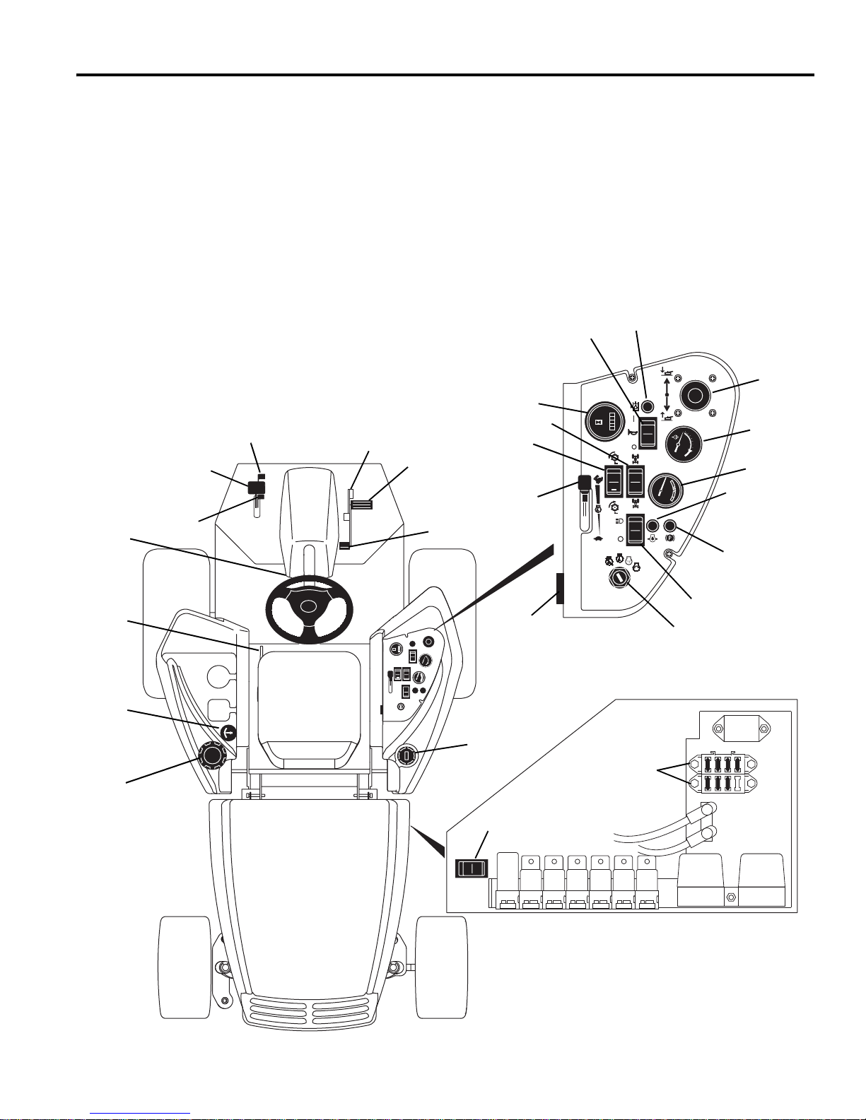
A Tilt Steering Lever
B1 Parking Brake Lock
B2 Parking Brake Release
C Parking Brake Pedal
D Mow Speed Stop
E Traction Pedal - Forward
F Traction Pedal - Reverse
G Seat Adjus tme nt
H Hydraulic Oil Cap
I Hydraulic Oil Light
J Fuel Cap
K Fuel Level Gauge
L Backlap Switch
M Hour Meter
N Water Temperature Gauge
O Volt Meter
P Engine Oil Light
Q Horn
R 2WD / 4WD Switch
S Raise / Lower Joystick
T Reel Switch
U Light Switch
V Ignition Switch
W Throttle
X Parking Brake Light
Y Fuse Blocks
Z Horn Switch
A
B
1
C
D
E
F
G
H
J
K
L
M
N
O
P
Q
R
S
T
U
V
W
X
Y
B
2
I
Z

4 CONTROLS
GB-8
4.2 CONTROL DESCRIPTIONS__________________________________________________
A. Steering Tilt Control
Pull lever up to release steering column. Tilt column
up or down to positi on des ired. Re lease lev er to lock
steering column in place.
B. Parking Brake Lock / Release
To lock parking brake, hold brake pedal (C) down and
press lock (B
1
) until it enga ges. To disengage, press
brake pedal release (B
2
).
C. Parking Brake
To engage parking brake press pedal down.
D. Mow Speed Stop
Limits forward speed while mowing. To operate at
lower travel speed while mowing, rotate lever so it
contacts stop screw (D1) on floor board when
forward travel pedal is pressed. To travel at full
speed, set lever in p osition shown (D3). Stop screw
(D2) can be adjusted to set specific mow speeds.
See the Parts & Maintenance manual.
Figure 4A
E. Forward Travel (Traction Pedal)
Press front of pedal down for forward travel. Release
pedal to slow tractor and stop. Do not press traction
pedal when parking brake is set and parking brake light
(W) is lit.
F. Reverse Travel (Traction Pedal)
Press rear of pedal down for reverse travel. Release
pedal to slow tractor and stop. Allow tractor to come to a
complete stop before reversing directions. Do not press
traction pedal when parking brake is set and parking
brake light (W) is lit.
G. Seat Adjustment
Pull left side lever out to adjust seat forward or
backward. To adjust spring tension under seat, turn
adjusting knob on front of seat.
H. Hydraulic Oil Cap
Fill to “green” area on gauge using clean hydraulic fluid
while machine is cool. Do not overfill
I. Hydraulic Oil Light
Alerts the operator of a low fluid level in
hydraulic tank. This light operates in
combination with the alarm. See Section 4.3.
J. Fuel Cap
Fill fuel tank with No. 2 diesel fuel, minimum cetane
rating of 45. Section 5.10
K. Fuel Level Gauge
Indicates current fuel level. Check fuel gauge daily
before starting machine.
Fill only to “‘green’ area on
gauge, do not top off tank.
Do not allow machine to run
out of fuel.
L. Backlap Switch
The backlap switch allows the mowers to rotate in
reverse for backlapping.
Forward - For normal operation (mowing) the
switch must be set to the FORWARD (cut)
position.
Reverse - When backlapping the mower must be
operated in the reverse direction. Set switch to
the REVERSE (backlap) position.
When backlapping the parking brake must be set and
both the reel switch (S) and backlap switch (L) must be
set to reverse. See Parts & Maintenance Manual
M. Hour Meter
Records engine operating hours. Use hour meter to
schedule periodic maintenance.
N. Temperature Gauge
Indicates engine coolant temperature. Normal operating
temperature should be between 160° - 230°F (71°110°C). If temperature rises above 230° (110°F), alarm
will sound. See Section 4.3.
O. Voltmeter
Indicates battery condition. During normal operation
meter should never be in the red area.
P. Engine Oil Pressure Light
The indicator will light if engine oil pressure drops
below 7 PSI (48 kPa). Stop engine immediately,
determine the cause, and co rrect the problem bef ore
resuming operation.
CAUTION
Never adjust steering while tractor is moving. Stop
unit and set parking brake before adjusting.
!
Full Speed Reduced Speed
D
1
D
2
D
3
E
F

CONTROLS 4
GB-9
Q. Horn
The alarm sounds to alert the operator to conditions
requiring immediate attention. See Section 4.3.
R. 2 WD / 4 WD Switch
Sets tractor into two or four wheel drive.
S. Raise / Lower Joystick
The joystick raises and lowers the mowers. Push
forward to lower mowers, pull back to raise mowers.
T. Reel Switch
The reel switch is a 3-position rocker type switch with a
neutral locking tab. It sets the mowers for either forward
or reverse rotation. Set mower switch in its OF F (center)
position when starting the tractor.
Forward - To mow, press switch to the
FORWARD (cut) position. With the switch in this
position, mowers will start automatically when
they are lowered and stop when they are raised. Return
switch to its center position to disable mowers.
Reverse - The mower can be operated in the
reverse direction for backlapping, running
vertical mowers, removing grass build-up in
mowers or dislodging objects binding mowers. To
reverse blade rotation, press switch to the REVERSE
position.
When backlapping, the parking brake must be set,
traction pedal in neutral and both the reel switch (Q) and
backlap switch (K) must be set to REVERSE. See Parts
& Maintenance Manual.
U. Light Switch
Controls operation of work lights.
V. Ignition Switch
The ignition switch has four positions. OFF - RUN GLOW PLUG - START. See Section 5.4.
W. Throttle
Controls engine speed. Run machine at full throttle
during normal machine operation.
X. Parking Brake Light
Indicates that the parkin g brake i s engaged. Par king
brake must be disengaged before depressing
traction pedal.
Y. Fuse Blocks
Used to provide circuit protection for electrical
systems. See Parts & Maintenance Manual.
Z. Horn Switch
This switch is used to test the alarm system or disable
the alarm after a low oil level has been detected. Keep
switch in its ON position when starting and operating
tractor. To test alarm, set switch to OFF and turn ignition
key to RUN. See
Section 4.3.

4 CONTROLS
GB-10
4.3 OPERATOR ALERTS_______________________________________________________
The machine monitors vital machine systems. It uses an
audible alarm and warning lights to alert the operator of
conditions requiring immediate action. When an alert
occurs, follow the general guidelines listed in the chart
below, and any specific actions outlined by the grounds
superintendent or service manager.
To test alarm system:
Turn ignition switch to RUN. Engine oil light will come on for
one second or more.
This system monitors:
1. Engine oil pressure
2. Engine coolant temperature
3. Hydraulic oil level
Alert Action
1. Engine Oil Pressure - Oil pressure
light comes on. Oil pressure low.
Stop tractor immediately, lower implements and shut off engine! Inspect oil
level in engine. If oil light remains on with oil at proper level, shut off engine and
tow or trailer tractor back to a service area. NEVER operate engine with oil light
on, severe damage to the engine can occur.
2. Engine Coolant Temperature
Alarm sounds. Engine coolant
temperature high.
Stop tractor immediately, lower implements and shu t off engine! Remove
debris such as leaves and grass clippings that may be restricting air flow through
front screen and area between radiator and oil cooler. If engine continues to run
hot, return tractor to a service area.
CAUTION: Engine coolant is under pressure. Turn engine off and allow
fluid to cool before checking fluid level or adding coolant to radiator.
3. Hydraulic fluid level - alarm
sounds and hydraulic fluid
warning light comes on.
Hydraulic fluid is below
recommended level.
Stop tractor immediately, lower implements and shut off engine! Visually
inspect tractor for obvious signs of leaks around connections, hoses and
hydraulic components. Return tractor to service area for maintenance.
CAUTION: Hydraulic fluid is under pressure. Turn engine off and allow
fluid to cool before checking fluid level or adding oil to hydraulic tank.
!
!

OPERATION 5
GB-11
5 OPERATION
5.1 DAILY INSPECTION______________________ ___ __ __________________________ __ _
1. Perform a visual i nspec tio n o f the entire unit, loo k for
signs of wear, loose hardware, and missing or
damaged components. Chec k for fuel or oil leaks to
ensure connections are tight and hoses and tubes
are in good condition.
2. Check the fuel supply, radiator coolant level,
crankcase oil and air cleaner indicator. All fluids
must be at the full level mark with engine cold.
3. Make sure all mowers are adjusted to the same
cutting height.
4. Check tires for proper inflation.
5. Test the Interlock System.
Note: For more detailed maintenance information,
adjustments and maintenance/lube charts, see the
Parts & Maintenance manual.
5.2 Interlock System_________________________________________________________________________
1. The Interlock System prevents the engine from
starting unless the parking brake is engaged, the
traction pedal is in neutral and the reel switch is OFF.
The system also stops the engine if the operator
leaves the seat with the reel switch ON, traction
pedal out of NEUTRAL, or parking brake
DISENGAGED.
2. Perform each of the following tests to insure the
Interlock System is functioning properly. Stop the
test and have the s ystem inspected and repaired if
any of the tests fail as listed below:
● the engine does not start in test 1;
● the engine does start during tests 2,3 or 4;
● the engine continues to run during tests 5 or 6.
3. Refer to the cha rt below for each t est and f ollow the
check (✔) marks across the chart. Shut engine off
between each test.
Test 1: Represents normal starting procedure. The
operator is seated, parking brake is engaged, the
traction pedal is in neutral, and the reel switch is
OFF. The engine should start.
Test 2: The engine must not start if the reel switch is
ON.
Test 3: The engine must not start if the parking brake
is DISENGAGED.
Test 4: The engine must not start if traction p edal is
not in neutral.
Test 5: Start the engine in the normal ma nner then
turn reel switch ON and lift your weight off the seat. ★
Test 6: Start the engine in the normal ma nner then
disengage parking brake an d lift your weight off the
seat. ★
★ Lift your weight off seat. The engine will shut down.
CAUTION
The daily inspection should be performed only when
the engine is off and all fluids are cold. Lower mowers
to the ground, engage the parking brake, Stop engine
and remove ignition key.
!
WARNING
Never operate equipment with the Interlock System
disconnected or malfunctioning. Do not disconnect or
bypass any switch.
!
Interlock System Check
Test Operator
Seated
Parking
Brake
Traction Pedal
in Neutral
Reel
Switch
Engine
Starts
Yes No Engaged Disengaged Yes No On Off Yes No
1 ✔✔ ✔ ✔✔
2 ✔✔ ✔✔ ✔
3 ✔✔✔✔✔
4 ✔ ✔ ✔✔✔
5 ✔
★
✔✔✔
★
6 ✔
★
✔✔ ✔
★
 Loading...