

Page 1

Safety, Operation & Maintenance Manual
WARNING: If incorrectly used this machine can cause
severe injury. Those who use and maintain this machine
should be trained in its proper use, warned of its dangers and
should read the entire manual before atte mpting to set up,
operate, adjust or service the machine.
GB
United
Kingdom
RJL 100 February 2010
Series: EK
Product code: AR30001
Series: FZ
Product code: AR30002
Series: GX
Product code: AR30003
Jacobsen AR3
24715G-GB (rev.4)
Page 2

© 2010, Ransomes Jacobsen Limited. All Rights Reserved
Page 3

en-3
JACOBSEN AR3
SAFETY, OPERATORS & MAINTENANCE MANUAL
1CONTENTS
2 INTRODUCTION
2.1 IMPORTANT................................................................4
2.2 PRODUCT IDENTIFICATION......................................4
2.3 GUIDELINES FOR THE DISPOSAL PRODUCTS .....4
3 SAFETY INSTRUCTIONS
3.1 OPERATING INSTRUCTIONS....................................6
3.2 SAFETY SIGNS...........................................................6
3.3 STARTING THE ENGINE............................................6
3.4 DRIVING THE MACHINE ............................................6
3.5 TRANSPORTING........................................................6
3.6 LEAVING THE DRIVING POSITION...........................7
3.7 SLOPES.......................................................................7
3.8 BLOCKED CUTTING CYLINDERS.............................7
3.9 ADJUSTMENTS, LUBRICATION AND
MAINTENANCE...........................................................7
4 SPECIFICATIONS
4.1 ENGINE SPECIFICATION........................................... 9
4.2 MACHINE SPECIFICATION........................................9
4.3 DIMENSIONS .............................................................. 9
4.4 VIBRATION LEVEL....................................................10
4.5 SLOPES......................................................................10
4.6 CUTTING UNIT SPECI F ICATION..............................11
4.7 RECOMMENDED LUBRICANTS...............................11
4.8 CUTTING PERFORM A NCE (AR EA) ............ .............11
4.9 CONFORMITY CERTIFICATES.................................12
5 DECALS .....................................................................14
5.2 INSTRUCTION DECA LS EC......................................14
5.1 SAFETY DECALS EC ................................................14
5.3 SAFETY DECALS USA.............................................. 15
5.4 INSTRUCTION DECA LS USA ..... ..............................15
6CONTROLS
6.1 INSTRUMENT PANEL ...............................................16
6.1A STARTER KEY SWITCH ...........................................17
6.1B WORKING LIGHT SWITCH .......................................17
6.1C PARKING BRAKES ...................................................17
6.1D CUTTING UNIT SWITCH.......... ......................... .........17
6.1E WEIGHT TRANSFER SWITCH..................................18
6.1F BLOCKED HYDRAULIC FILTER INDICATOR
LAMP..........................................................................18
6.1G CHARGE WARNING LAMP.......................................18
6.1H ENGINE COOLANT TEMPERATURE
WARNING LAMP .......................................................18
6.1J ENGINE OIL PRESSURE WARNING LAMP .............18
6.1K CONTROL MODULE FAULT WARNING LAMP .......19
6.1L ENGINE PREHEAT INDICATOR LAMP....................19
6.1M THROTTLE CONTROL LEVE R ............... .................19
6.1N JOYSTICK UNIT LIFT/LOWER CONTROL ...............19
6.1P MULTI-FUNCTION GAUGE .......................................20
6.2 TRACTION FOOT PEDAL ........................................21
6.3 STEERING TILT CONTROL ......................................21
6.4 POWER OUTLET....................................................... 21
6.5 PARKING BRAKE RELEASE VALVE.......................22
6.6 TRANSPORT LATCHES............................................22
7 OPERATION
7.1 DAILY INSPECTION ..................................................23
7.2 OPERATOR PRESENCE AND SAFETY
INTERLOCK.............................................................. 24
7.3 OPERATING PROCEDURE.......................................25
7.4 FITTING THE CUTTING UNITS
TO THE MACHINE .... .................................................26
7.5 STARTING THE ENGINE ..........................................27
7.6 DRIVING ....................................................................27
7.7 MOWING.....................................................................27
7.8 TO STOP THE ENGINE.............................................27
7.9 MOWING ON SLOPES...............................................28
CONTENTS PAGE
8 MAINTENANCE & LUBRICATION
8.1 MAINTENANCE & LUBRICATION CHART...............32
8.2 ENGINE LUBRICATION.............................................34
8.3 ENGINE: FAN BELT........... ........................................34
8.4 ENGINE COOLANT....................................................35
8.5 HYDRAULIC SYSTEM...............................................36
8.6 HYDRAULIC TEST PORTS........................................36
8.7 FUEL SYSTEM................................................. ..........38
8.8 AIR CLEANER.................... ........................................39
8.9 BATTERY ...................................................................39
8.10 MACHINE MAINTENANCE..................... ...................40
8.11 FREEWHEEL CONTROL...........................................40
9 ADJUSTMENTS
9.1 TRACTION CONTROL PEDAL..................................41
9.2 WEIGHT TRANSFER ADJUSTMENT........................41
9.3 HEIGHT OF CUT .......................................................42
9.4 BLADE CHANGE .......................................................44
9.5 BLADE SHARPENING...............................................44
9.6 SPEED LIMITER............... ............. .............................45
9.7 SEAT (MILSCO CE200).................... .........................45
9.8 SEAT (MICHIGAN).......................... ...........................46
9.9 GENERAL INSTRUCTIONS FOR
GRAMMER EATS.......................................................47
9.10 SEAT (GRAMMER MSG85).......................................49
9.11 AIR SUSPENSION SEAT (MSG75 -521) ...................50
9.11.1 WEIGHT ADJUSTMENT ............................................50
9.11.2 FORE/AFT ADJUSTMENT.........................................50
9.11.3 BACKREST EXTENSION...........................................51
9.11.4 SEAT HEATER................... ............. ...........................51
9.11.5 LUMBAR SUPPOR T..................................................51
9.11.6 ARMRESTS................................................................52
9.11.7 ARMREST ADJUSTMENT.........................................52
9.11.8 BACKREST ADJUSTMENT.......................................52
9.11.9 MAINTENANCE..........................................................53
10 ACCESSORIES
10.1 OPS FRAME (LMAC164)..........................................54
10.2 TRANSPORT LATCH KIT (LMAC174) .....................54
10.3 WORKING LAMP KIT (LMAC163)............................54
11 TROUBLESHOOTING
11.1 GENERAL...................................................................55
11.2 QUALITY OF CUT TROUBLESHOOTING.................66
12 SCHEMATICS
12.1 HYDRAULIC CIRCUIT................................................64
12.2 ELECTRICAL CIRCUIT INSTRUMENT......................66
12.3 ELECTRICAL CIRCUIT MAIN....................................68
12.4 ELECTRICAL CIRCUIT FUSES AND RELAYS.........70
13 TORQUES
13.1 TORQUES...................................................................72
14 GUARANTEE
14 GUARANTEE / SALES & SERVICE ..........................73
CONTENTS PAGE
Page 4
en-4
JACOBSEN AR3
SAFETY, OPERATORS & MAINTENANCE MANUAL
2 INTRODUCTION
2.1 IMPORTANT
IMPORTANT: This is a precision machine and the service obtained from it depends on the way it is operated
and maintained.
This SAFETY AND OPERATORS MANUAL should be regarded as part of the machine. Suppliers of both new
and second-hand machines are advised to retain documentary evidence that this manual was provided with the
machine.
This machine is designed solely for use in customary grass cutting operations. Use in any other way is considered
as contrary to the intended use. Compliance with and strict adherence to the conditions of operation, service
and repair as specified by the manufacturer, also constitute essential elements of the intended use.
Before attempting to operate this machine, ALL operators MUST read through this manual and make themselves
thoroughly conversant with Safety Instructions, controls, lubrication and maintenance.
Accident prevention regulations, all other generally recognized regulations on safety and occupational medicine,
and all road traffic regulations shall be observed at all times.
Any arbitrary modifica tions carried out on this machin e may relieve the ma nufact urer of liabilit y for any resulting da mage or
injury.
2006/42/EC
These are the Original instructions verified by Ransomes Jacobsen Limited.
2.2 PRODUCT IDENTIFICATION
A Maximum front axle load in Kg (for machines
being driven on the highway)
B Gross weight (mass) in Kg
C Maximum rear axle load in Kg (for machines
being driven on the highway)
D Power in Kw
E Date code
F Machine type (Designation)
G Product code
H Product name
J Serial number
Serial Plate Location
The serial plate A is located on the chassis under the
operators seating position.
KgKwKg
Kg
West Road
Ransomes Europark
Ipswich IP3 9TT
England
A
B
CD
E
F
G
H
J
A
Page 5

en-5
JACOBSEN AR3
SAFETY, OPERATORS & MAINTENANCE MANUAL
2 INTRODUCTION
2.3 GUIDELINES FOR THE DISPOSAL OF
SCRAP PRODUCTS
2.3.1 DURING SERVICE LIFE
Used oil, oil filters and engine coolant are hazardous
materials and should be handled in a safe and
environmentally responsible way.
In the event of a fluid leak, contain the spill to prevent
it entering the ground or drainage system. Local
legislation will dictate how such spills are to treated.
Following the maintenance procedures laid out in this
manual will ensure that the impact the machine has
on the local environment is controlled.
When it has been identified that a turf care product
has no further functional value and requires disposal,
the following actions should be taken.
2.3.2 EN D OF SERVICE LIFE
These guidelines should be used in conjunction with
applicable Health, Safety and Envi r onm enta l
legislation and use of approved local facilities for
waste disposal and recycling.
• Position the machine in a suitable location
for any necessary lifting equipment to be
used.
• Use appropriate tools and Personal
Protective Equipment (PPE) and take
guidance from the technical manuals
applicable to the machine.
• Remove and store appropriately:
1. Batteries
2. Fuel residue
3. Engine coolant
4. Oils
• Disassemble the structure of the machine
referring to the technical manuals where
appropriate. Special attention should be
made for dealing with ‘stored energy’ within
pressurised elements of the machine or
tensioned springs.
• Any items that still have a useful service life
as second hand components or can be reserviced should be separated and returned
to the relevant centre.
• Other worn out items should be separat ed
into material groups for recycling and
disposal consistent with available facilities.
More common separation types are as
follows:
•Steel
• Non ferrous metals
•Aluminium
•Brass
• Copper
•Plastics
• Identifiable
• Recyclable
• Non recyclable
• Not identified
• Rubber
• Electrical & El ectronic
Components
• Items that cannot be separated
economically into different material groups
should be added to the ‘General waste’
area.
• Do not incinerate waste.
Finally update machinery records to indicate that the
machine has been taken out of service and scrapped.
Provide this serial number to Jacobsen Warranty
department to close off relevant records.
Page 6

en-6
JACOBSEN AR3
SAFETY, OPERATORS & MAINTENANCE MANUAL
3 SAFETY INSTRUCTIONS
This safety symbol indicates important safety
messages in this manual. When you see this symbol,
be alert to the possibility of injury, carefully read the
message that follows, and inform other operators.
3.1 OPERATING INSTRUCTIONS
• Ensure that the instructions in this book are
read and fully understood.
• No person should be allowed to operate
this machine unless they are fully
acquainted with all the controls and the
safety procedures.
• Never allow children or people unfamiliar
with these instructions to use this machine.
Local regulations may restrict the age of the
operator.
3.2 SAFETY SIGNS
• It is essential all safety labels are kept
legible, if they are missing or illegible they
must be replaced. If any part of the machine
is replaced and it originally carried a safety
label, a new label must be affixed to the
replacement part. New safety labels are
obtainable from Ransomes dealers.
3.3 STARTING THE ENGINE
• Before starting the e ngine check that the
brakes are applied, drives are in neutral,
guards are in position and intact, and
bystanders are clear of the machine.
• Do not run the engine in a building without
adequate ventilation.
3.4 DRIVING THE MACHINE
• Before moving the machine, check to
ensure that all parts are in good working
order, paying particular attention to brakes,
tyres, steering and the security of cutting
blades.
• Replace faulty silencers, mow only in
daylight or good artificial light
• Always observe the Highway Code both on
and off th e road s. Ke ep al ert an d aw are at
all times. Watch out for traffic when
crossing or near roadways.
• Stop the blades rotating before crossing
surfaces other than grass.
• Remember that some people are deaf or
blind and that children and animals can
be unpredictable.
• Keep travelling speeds low enough for an
emergency stop to be effective and safe
at all times, in any conditions.
• Remove or avoid obstructions in the area
to be cut, thus reducing the possibility of
injury to yourself and/or bystanders.
• When reversing, take special care to
ensure that the area behind is clear of
obstructions and/or bystanders. DO NOT
carry passengers.
• Keep in mind that the operator or user is
responsible for accidents or hazards
occurring to other people or their
property.
• When the machine is to be parked, stored
or left unattended, lower the cutting
means unless the transport locks are
being used.
• While mowing, always w ear substantial
footwear and long trousers. Do not
operate the equipment when barefoot or
wearing open sandals.
• Check the grass catcher frequently for
wear or deterioration. After striking a
foreign object Inspect the lawnmower for
damage and make repairs before
restarting and operating the equipment.
• If the machine starts to vibrate
abnormally, check immediately.
3.5 TRANSPORTING
• Drive the machine with due consideration
of road and surface conditions, inclines
and local undulations.
• Sudden decelerating or braking can
cause the rear wheels to lift.
• Remember that the stability of the rear of
the machine is reduced as the fuel is
used.
Page 7

en-7
JACOBSEN AR3
SAFETY, OPERATORS & MAINTENANCE MANUAL
3 SAFETY INSTRUCTIONS
3.6 LEAVING THE DRIVIN G PO SI T ION
• Park the machine on level ground.
• Before leaving the driving position, stop the
engine and make sure all moving parts are
stationary. Apply brakes and disengage all
drives. Remove the starter key.
3.7 SLOPES
TAKE EXTRA CARE WHEN WORKING ON
SLOPES
• Local undulations and sinkage will change
the general slope. Avoid ground conditions
which can cause the machine to slide.
• Keep machine speeds low on slopes and
during tight turns.
• Sudden decelerating or braking can cause
the rear wheels to lift. Remember there is
no such thing as a “safe” slope.
• Travel on grass slopes requires particular
care.
• To minimize the possibility of overturning,
the safest method for operating on hills and
terraces is to travel up and down the face
of the slope (vertically), not across the face
(horizontally). Avoid unnecessary turns,
travel at reduced speeds, and stay alert for
hidden hazards.
DO NOT USE ON SLOPES GREATER THAN 15°
IMPORTANT: When working on any slope select
weight transfer, Adjust to provide adequate traction.
3.8 BLOCKED CUTTING UNITS
• Stop the engine and make sure all moving
parts are stationary.
• Apply brakes and disengage all drives.
• Release blockages with care. Keep all parts of
the body away from the cutting edge. Beware
of energy in the drive which can cause rotation
when the blockage is released.
• Keep other people away from the cutting units
as rotation of one can cause the others to
rotate.
3.9 ADJUSTMENTS, LUBRICATION AND
MAINTENANCE
• Stop the engine and make sure all moving
parts are stationary.
• Apply brakes and disengage all drives.
• Read all the appropriate servicing instructions.
• Use only the replacement parts supplied by
the original manufacturer.
• When adjusting the cutting cylinders take care
not to get hands and feet trapped when rotating
cylinders.
• Make sure that other people are not touching
any cutting units, as rotation of one cylinder
can cause the others to rotate.
• To reduce the fire hazard, keep the engine,
silencer and battery compartments free of
grass, leaves or excessive grease.
• Replace worn or damaged parts for safety.
• When working underneath lifted parts or
machines, make sure adequate support Is
provided.
• Do not dismantle the machine without
releasing or restraining forces which can
cause parts to move suddenly.
• Do not alter engine speed above maximum
quoted in Engine Specification. Do not change
the engine governor settings or overspeed the
engine. Operating the engine at excessive
speed may increase the hazard of personal
injury.
• When refuelling, STOP THE ENGINE, DO
NOT SMOKE. Add fuel before starting the
engine, never add fuel while the engine is
running.
• Use a funnel when pouring fuel from a can into
the tank.
• Do not fill the fuel tank beyond the bottom of
the filler neck.
• Replace all fuel tank and container caps
securely.
• Store fuel in containers specifically designed
for this purpose.
• Refuel outdoors only and do not smoke while
refuelling.
• If fuel is spilled, do not attempt to start the
engine but move the machine away from the
area of spillage and avoid creating any source
of ignition until fuel vapours have dissipated.
• Allow the engine to cool before storing in any
enclosure.
• Never store the equipment with fuel in the tank
inside a building where fumes may reach an
open flame or spark.
• If the fuel tank has to be drained, this should
be done outdoors.
• Do not spill fuel onto hot components.
• When servicing batteries, DO NOT SMOKE,
and keep naked lights away.
• Do not place any metal objects across the
terminals.
Page 8
en-8
JACOBSEN AR3
SAFETY, OPERATORS & MAINTENANCE MANUAL
3 SAFETY INSTRUCTIONS
• When Pressu re Washing the Mower. Turn the
engine off and remove the starter key.
If the engine has been running, it should be
allowed to cool sufficient ly to prevent dama ge
to the block and exhaust manifold. Never force
water into any electrical components, the air
cleaner or exhaust muffler as water could enter
the engine cylinder and cause damage.
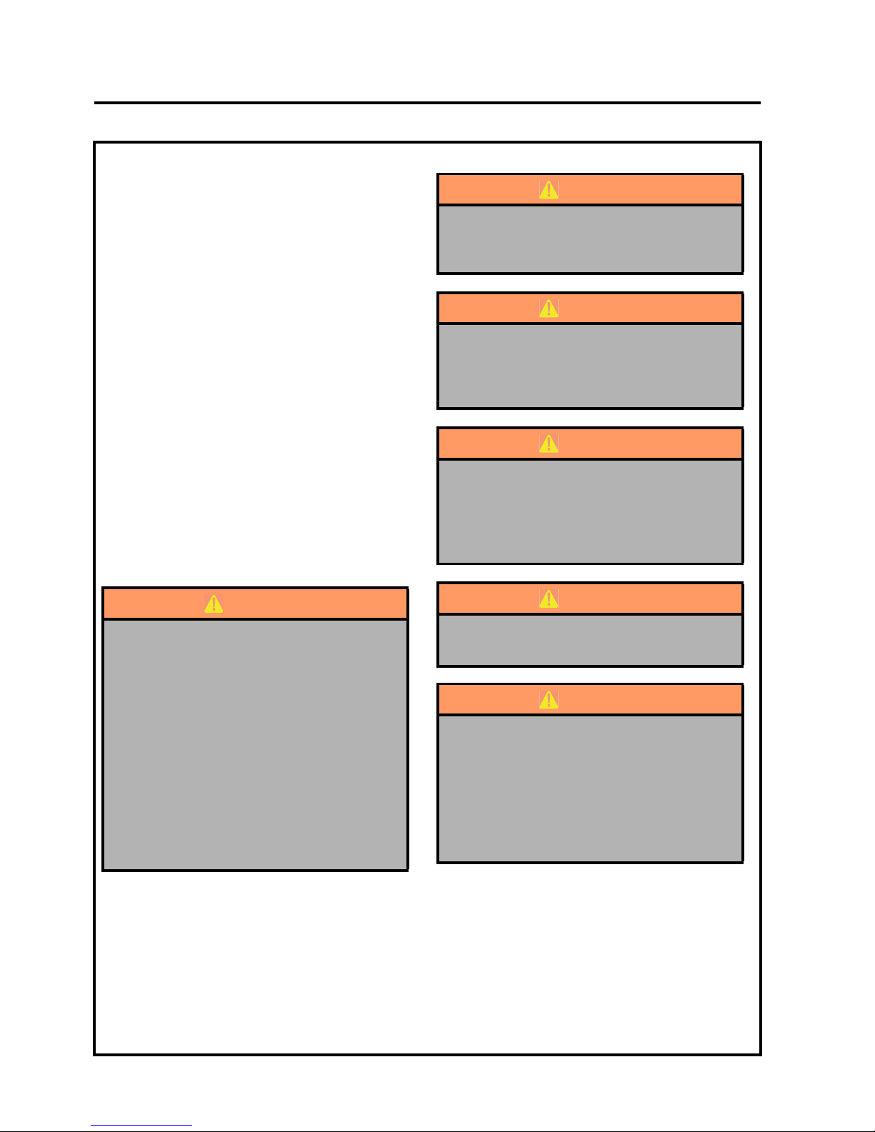
DANGER - Indicates an imminently hazardous
situation which, if not avoided, WILL result in death
or serious injury.
WARNING - Indicates a potentially hazardous
situation which, if not avoided, COULD result in death
or serious injury.
CAUTION - Indicates a potentially hazardous
situation which, if not avoided, MAY result in minor
or moderate injury and property damage. It may also
be used to alert against unsafe practices.
IMPORTANT: Transport speed is for highway use
only. Never select transport speed on grass
areas or uneven or unsurfaced roads or tracks.
WARNING
Before releasing transport latches it is
important that all cutting units are fully raised.
1. Park the machine on level ground.
2. With the engine running at operating speed
raise the cutting units to their maximum
position by operating lift levers whilst seated
in the driving position.
3. Disengage drives, stop the engine and make
sure all moving parts are stationary. Apply
brakes and remove the starter key.
4.transport latches can now be released.
WARNING
Ear Protection Should be Worn When
Operating Machines with Operator Ear
Noise Levels above 85dB(A)Leq.
WARNING
Batteries produce explosive gases and
contain corrosive acid and supply levels of
electrical current high enough to cause
burns.
WARNING
California Proposition 65
Engine Exhaust, some of its constituents,
and certain vehicle components contain or
emit chemicals known to the state of
California to cause cancer and birth defects
or other reproductive harm.
WARNING
DO NOT USE ON SLOPES GREATER THAN
15°
WARNING
To prevent serious injury from hot, high pressure
oil, never use your hands to check for oil leaks,
use paper or cardboard.
Hydraulic fluid escaping under pressure can
have sufficient force to penetrate skin. If fluid is
injected into the skin it must be surgically
removed within a few hours by a doctor familiar
with this form of injury or gangrene may result.
Page 9
en-9
JACOBSEN AR3
SAFETY, OPERATORS & MAINTENANCE MANUAL
4 SPECIFICATIONS
4.1 ENGINE SPECIFICATION
TYPE: Kubota 24.5KW (32.8HP) @
3000 RPM, 3 cylinder (in line)
Turbo charged Diesel engine, 4
stroke, water cooled, 1123cc
(68.53 cu.in) with 12V 1KW
electric start, 12V 30Amp
Alternator
Model: D1105-T-E3B-RNUK-3
Maximum Speed: 3150 ± 50 RPM (No load)
Idle Speed: 1650 ± 25 RPM
Oil Sump Capacity: 5.1 litres (1.35 US gals)
Fuel: No. 2-D Diesel fuel (ASTM D975)
4.2 MACHINE SPECIFICATION
Frame construction: Heavy duty formed steel
chassis with box section frame
rails.
Cutting unit drive: Fixed displacement hydraulic
motors.
Transmission: 3-wheel drive. Direct coupled
variable displacement pump to
direct coupled 200cc/rev fr ont,
400cc/rev rear wheel motor.
Speeds:
Cutting: 0 - 9.5 km/h (0 - 5.9 mph)
FORWARD
Transport: 0 - 14 km/h (0 - 8.5 mph)
FORWARD
Reverse: 0 - 6 km/h (0 -3.7 mph)
Steering: Hydrostatic power steering, with
adjustable tilt steering wheel.
Ground pressure: 1 kg/cm
2
(14p.s.i.)
Brakes: Hydrostat ic braki ng w ith hydr aul ic
parking brakes on front wheels.
Fuel Tank
Capacity: 45.4 litres (12 US galls)
Hydraulic Tank
Capacity: 25 litres (6.6 US galls)
Battery: Exide 093 (SAE 500)
4.3 DIMENSIONS
A Width of cut 183 cm 72 inches
B Transport width 200 cm 79 inches
C Overall height without ROPS 134 cm 52.7 inches
D Overall height with ROPS, add 48 cm 19 inches
E Overall Length 312 cm 123 inches
F Wheel Track 132 cm 52 inches
G Wheel Base 151 cm 59.75 inches
H Weight of Machine - Diesel 860 kg 1896 lb
J Weight of Cutt ing Unit (each) 91 kg 201 lb
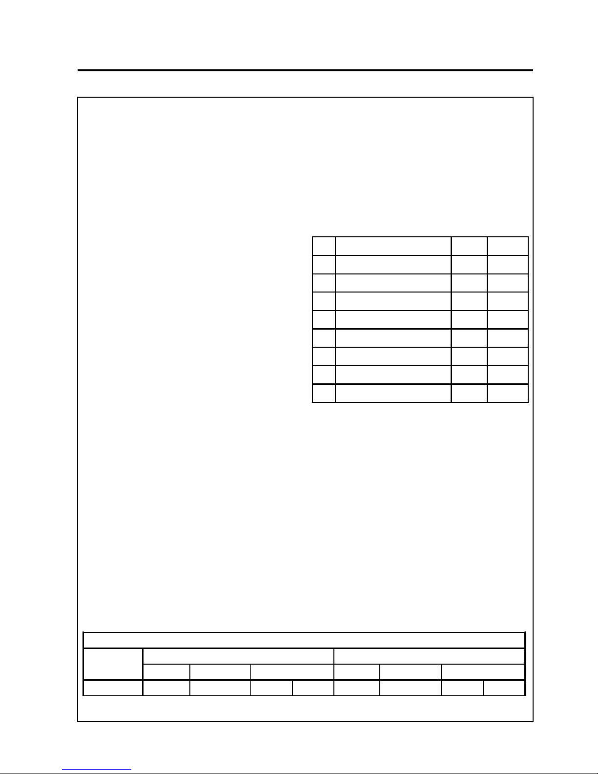
TYRE PRESSURES
Product
Front Wheel Rear Wheel
Tyre Size Tyre Type Tyre Pressure Tyre Size Tyre Type Tyre Pressure
AR3 20 x 12.00 - 10
Turf Trac 4pr 14 - 20 psi 1.00 - 1.37 bar
20 x 10.00 - 8
Turf Trac 4pr 14 - 22 psi 1.00 - 1.51 bar
Page 10
en-10
JACOBSEN AR3
SAFETY, OPERATORS & MAINTENANCE MANUAL
4 SPECIFICATIONS
4.4 VIBRATION LEVEL
When the machine was tested for hand/arm vibration
levels. The operator was seated in the normal
operating position with both hands on the steering
mechanism. The engine was running and the cutting
device was rotating with the machine stationary.
The Machinery Safety Directive 98/37/EC
By compliance to:
The Lawnmower Standard EN836:1997
Referenced to hand/Arm: EN1033:1996
Information Supplied for Physical Agents
Directive 2002/44/EC
By reference to:
Hand/Arm Standards: BS EN ISO 5349-1 (2001)
BS EN ISO 5349-2 (2001)
When the machine was tested for Whole Body
vibration levels. The operator was seated in the
normal operating position with both hands on the
steering mechanism. The cutting device was rotating
with the machine driven in a straight line at 6 Km/hr
on a level fre s hly cut lawn.
The Machinery Safety Directive 98/37/EC
By compliance to:
Whole Body EN1032:2003
Information Supplied for Physical Agents
Directive 2002/44/EC
By reference to:
Whole Body Standards BS EN ISO 2631-1 (1 997 )
4.5 SLOPES
DO NOT USE ON SLOPES GREATER THAN 15°
The slope 15° was calculated using static stability
measurements according to the requirements of
EN 836:1997
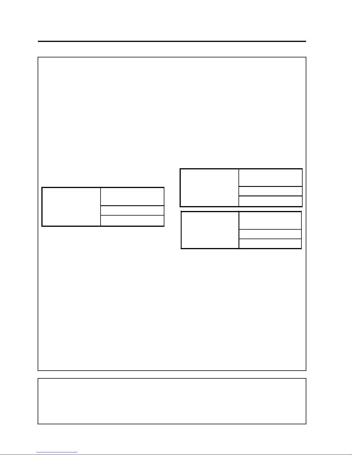
Jacobsen AR3
Series:EK, FZ & GX
Hand / Arm Acceleration
level
Max LH or RH
Accelerations m/s
2
Mean Value of X, Y, Z Aeq
1.69
Jacobsen AR3
Series:EK, FZ & GX
Whole Body Acceleration
level
Max LH or RH Foot
Accelerations m/s
2
Mean Value of X, Y, Z Aeq
0.88
Jacobsen AR3
Series:EK, FZ & GX
Whole B o dy Acceleration
level
Seat Location
Accelerations m/s
2
Mean Value of X, Y, Z Aeq
0.59
Page 11
en-11
JACOBSEN AR3
SAFETY, OPERATORS & MAINTENANCE MANUAL
4.6 CUTTING UNIT SPECIFICATION
General: Three 686mm (27in) rotary mulching/rear
discharge decks.
Drive: Fixed displacement hydraulic motors
directly coupled to cutting unit.
Control: Cutting unit lift lever with automatic shut off
and safety interlock restart.
Construction:
Heavy duty, welded pressed steel.
Cutting Blades:
Rear Discharge
Low Lift Blade
Height of cut:
Adjustable in 6 mm (0.25 in) incremen ts
19 mm(0.75 in) to 90mm (3.5 in)
Rear roller:
Series EK 76mm (3in) diameter smooth roller.
Series FZ 90mm (3.5in) diameter smooth roller
4.7 RECOMMENDED LUBRICANTS
Engine oil: Should be to MIL-L-2104C or to
A.P.I. Classification CD grades.
[10W-30]
Hydraulic Oil: GreensCare 46 (ISO 46) Bio
Degradable Oil
4 SPECIFICATIONS
Grease: K NATE (RJL No. 4213860), or
equivalent to MIL-G-23549C,
MIL-G-2345C, DIN 51 825,
DIN 51 818.
4.8 CUTTING PERFORMANCE (AREA)
1.0 hectares/hr. at 9.5 km/hr. ( 2.6 acres/hr at 5.9
mph)
10% allowance is included for normal overlaps and
turning at the end of each cut.
TEMPERATURE VISCOSITY
ABOVE 25°C (77°F) SAE30 or
SAE10W-30
SAE10W-40
0°C to 25°C (32°F to 77°F) SAE20 or
SAE10W-30
SAE10W-40
BELOW 0°C (32°F) SAE 10W or
SAE10W-30
SAE10W-40
Page 12

en-12
JACOBSEN AR3
SAFETY, OPERATORS & MAINTENANCE MANUAL
4 SPECIFICATIONS
4.9 CONFORMITY CERTIFICATES
Business name and full address of the manufacturer ƒ Ɍɴɪɝɨɜɫɤɨ ɢɦɟ ɢ ɩɴɥɟɧ ɚɞɪɟɫ ɧɚ ɩɪɨɢɡɜɨɞɢɬɟɥɹ ƒ
Obchodní jméno a plná adresa výrobce ƒ Producentens firmanav n og fulde adresse ƒ Bedrijfsnaam en volledig adres van de fabrikant ƒ Tootja ärinimi ja täielik aadress ƒ
Valmistajan toiminimi ja täydellinen osoite ƒ Nom commercial et adresse c omplète du fabricant ƒ Firmenname und vollständige Adresse des Herstellers ƒ ǼʌȦȞȣȝȓĮ țĮȚ
IJĮȤȣįȡȠȝȚțȒ įȚİȪșȣȞıȘ țĮIJĮıțİȣĮıIJȒ ƒ A gyártó üzleti neve és teljes címe ƒ Ragione sociale e indirizzo completo del fabbricante ƒ UzƼƝmuma nosaukums un pilna ražotƗja
adrese ƒ Verslo pavadinimas ir pilnas gamintojo adresas ƒ Isem kummerƛjali u indirizz sƫiƫ tal-fabbrikant ƒ Nazwa fir my i peãny adres producenta ƒ Nome da empresa e endereço
completo do fabricante ƒ Denumirea comercială úi adresa com pletă a producătorului ƒ Obchodný názov a úplná adresa výrobcu ƒ Naziv podjetja in polni naslov proizvajalca ƒ
Nombre de la empresa y dirección completa del fabricante ƒ Tillverkarens företagsnam n och kompletta adress ƒ Fyrirtækisheiti og fullt heimilisfang framleiðanda ƒ Firmanavn og
full adresse for produsenten
Ransomes Jacobsen Limited
West Road, Ransomes Europark,
Ipswich, England, IP3 9TT
Product Code ƒ Ʉɨɞ ɧɚ ɩɪɨɞɭɤɬɚ ƒ Kód výrobku ƒ Produktkode ƒ Productcode ƒ Toote kood ƒ Tuotekoodi ƒ Code produit ƒ Produktcode ƒ ȀȦįȚțȩȢ ʌȡȠȧȩȞIJȠȢ ƒ Termékkód ƒ
Codice prodotto ƒ Produkta kods ƒ Produkto kodas ƒ Kodiƛi tal-Prodott ƒ Kod produktu ƒ Código do Produto ƒ Cod produs ƒ Kód výrobku ƒ Oznaka proizvoda ƒ Código de producto
ƒ Produktkod ƒ Vörunúmer ƒ Produktkode
AR 30001
AR30002
AR30003
Machine Name ƒ ɇɚɢɦɟɧɨɜɚɧɢɟ ɧɚ ɦɚɲɢɧɚɬɚ ƒ
Název stroje ƒ Maskinnavn ƒ Machinenaam ƒ Masina nimi ƒ Laitteen nimi ƒ Nom de la machine ƒ Maschinenbezeichnung ƒ
ȅȞȠȝĮıȓĮ ȝȘȤĮȞȒȝĮIJȠȢ ƒ Gépnév ƒ Denominazione della macchina ƒ IekƗrtas nos aukums ƒ Mašinos pavadinimas ƒ Isem tal-Magna ƒ Nazwa urządzenia ƒ Nome da Máquina ƒ
Numele echipamentului ƒ Názov stroja ƒ Naziv stroja ƒ Nombre de la máquina ƒ Maskinens namn ƒ Heiti tækis ƒ Maskinnavn
Jacobsen AR3
Designation ƒ ɉɪɟɞɧɚɡɧɚɱɟɧɢɟ ƒ Oznaþení ƒ Betegnelse ƒ Benaming ƒ Nimetus ƒ Tyyppimerkintä ƒ Pažymơjimas ƒ
Bezeichnung ƒ ȋĮȡĮțIJȘȡȚıȝȩȢ ƒ Megnevezés ƒ Funzione ƒ ApzƯmƝjums ƒ Lithuanian ƒ Denominazzjoni ƒ Oznaczenie ƒ
Designação ƒ
SpecificaĠie ƒ Oznaþenie ƒ Namen stroja ƒ Descripción ƒ Beteckning ƒ Merking ƒ Konstruksjon
Ride on Rotary Mower
Serial Number ƒ ɋɟɪɢɟɧ ɧɨɦɟɪ ƒ Sériové þíslo ƒ Serienummer ƒ Serienummer ƒ Seerianumber ƒ Valmistus numero ƒ Numéro de série ƒ Seriennummer ƒ ȈİȚȡȚĮțȩȢ ĮȡȚșȝȩȢ ƒ
Sorozatszám ƒ Numero di serie ƒ SƝrijas numurs ƒ Serijos numeris ƒ Numru Serjali ƒ Numer seryjny ƒ Número de Série ƒ Număr de serie ƒ Sériové þíslo ƒ Serijska številka ƒ
Número de serie ƒ Serienummer ƒ Raðnúmer ƒ Serienummer
EK000301 - EK999999
FZ000301 - FZ999999
GX000301 - GX999999
Engine ƒ Ⱦɜɢɝɚɬɟɥ ƒ Motor ƒ Motor ƒ Motor ƒ Mootor ƒ Moottori
ƒ Moteur ƒ Motor ƒ ȂȘȤĮȞȒ ƒ Modulnév ƒ Motore ƒ DzinƝjs ƒ Variklis ƒ Saƫƫa Netta Installata ƒ Silnik ƒ Motor ƒ Motor
ƒ Motor ƒ Motor ƒ Motor ƒ Motor ƒ Vél ƒ Motor
Kubota D1105-T-E3B-RANUK-1
Net Installed Power ƒ ɇɟɬɧɚ ɢɧɫɬɚɥɢɪɚɧɚ ɦɨɳɧɨɫɬ ƒ ýistý instalovaný výkon ƒ Installeret nettoeffekt ƒ Netto geïnstalleerd vermogen ƒ Installeeritud netovõimsus ƒ Asennettu
nettoteho ƒ Puissance nominale nette ƒ Installierte Nettoleis tung ƒ ȀĮșĮȡȒ İȖțĮIJİıIJȘȝȑȞȘ ȚıȤȪȢ ƒ Nettó beépített teljesítmény ƒ Potenza netta installata ƒ ParedzƝtƗ tƯkla jauda ƒ
Grynoji galia ƒ Wisa’ tal-Qtugƫ ƒ Moc zainstalowana netto ƒ Potência instalada ƒ Puterea instalat
ă netă ƒ ýistý inštalovaný výkon ƒ Neto vgrajena moþ ƒ Potencia instalada neta ƒ
Nettoeffekt ƒ Nettóafl vélar ƒ Netto installert kraft
24.5 kW @ 3000 RPM
Cutting Width ƒ ɒɢɪɨɱɢɧɚ ɧɚ ɪɹɡɚɧɟ ƒ ŠíĜka Ĝezu ƒ Skærebredde ƒ Maaibreedte ƒ Lõikelaius ƒ Leikkuuleveys ƒ Largeur de coupe ƒ Schnitt breite ƒ ȂȒțȠȢ ȝȚıȚȞȑȗĮȢ ƒ Vágási
szélesség ƒ Larghezza di taglio ƒ Griešanas platums ƒ Pjovimo plotis ƒ Tikkonforma m ad-Direttivi ƒ SzerokoĞü ciĊcia ƒ Largura de Corte ƒ Lă
Ġ
imea de tăiere ƒ Šírka záberu ƒ Širina
reza ƒ Anchura de corte ƒ Klippbredd ƒ Skurðbreidd ƒ Klippebredde
173cm to 183cm
Conforms to Directives ƒ ȼ ɫɴɨɬɜɟɬɫɬɜɢɟ ɫ ɞɢɪɟɤɬɢɜɢɬɟ ƒ SplĖuje podmínky smČrnic ƒ Er i overensstemmelse med direktiver ƒ Voldoet aan de richtlijnen ƒ Vastab direktiividele ƒ
Direktiivien mukainen ƒ Conforme aux directives ƒ Entspricht Richtlinien ƒ ǹțȠȜȠȣșȒıIJİ ʌȚıIJȐ IJȚȢ ȅįȘȖȓİȢ ƒ Megfelel az irányelveknek ƒ Conforme alle Direttive ƒ Atbilst
direktƯvƗm ƒ Atitinka direktyvǐ reikalavimus ƒ Valutazzjoni tal-Konformità ƒ Dyrektywy związane ƒ Cumpre as Directivas ƒ Respectă Directivele ƒ Je v súlade so smernicami ƒ
Skladnost z direktivami ƒ Cumple con las Directivas ƒ Uppfyller direktiv ƒ Samræmist tilskipunum ƒ I samsvar med direktiv
2006/42/EC
2004/108/EC
2000/14/EC
Conformity Assessment ƒ Ɉɰɟɧɤɚ ɡɚ ɫɴɨɬɜɟɬɫɬɜɢɟ ƒ Hodnocení plnČní podmínek ƒ Overensstemmelsesvurdering ƒ
Conformiteitsbeoordeling ƒ Vastavushindamine ƒ Vaatimus tenmukaisuuden arviointi ƒ Evaluation de conformité ƒ
Konformitätsbeurteilung ƒ ǻȚĮʌȓıIJȦıȘ ȈȣȝȝȩȡijȦıȘȢ ƒ MegfelelĘség-értékelés ƒ Valutazione della conformità ƒ
AtbilstƯ
bas novƝrtƝjums ƒ Atitikties Ƴvertinimas ƒ Livell tal-Qawwa tal-ƪoss Imkejjel ƒ Ocena zgodnoĞci ƒ
Avaliação de Conformidade ƒ Evaluarea conformităĠii ƒ Vyhodnotenie zhodnosti ƒ Ocena skladnosti ƒ
Evaluación de conformidad ƒ Bedömning av överensstämmelse ƒ Samræmismat ƒ Konformitetsvurdering
2006/42/EC Annex VIII
Measured Sound Power Level ƒ ɂɡɦɟɪɟɧɨ ɧɢɜɨ ɧɚ ɡɜɭɤɨɜɚ ɦɨɳɧɨɫɬ ƒ NamČĜený akustický výkon ƒ Målte lydstyrkeniveau ƒ Gemeten geluidsniveau ƒ Mõõdetud helivõimsuse
tase ƒ Mitattu äänitehotaso ƒ Niveau de puissance sonore mesuré ƒ Gemessener Sc halldruckpegel ƒ ȈIJĮșȝȚıȝȑȞȠ İʌȓʌİįȠ ȘȤȘIJȚțȒȢ ȚıȤȪȠȢ ƒ Mért hangteljesítményszint ƒ Livello
di potenza sonora misurato ƒ IzmƝrƯtais skaƼas jaudas lƯmenis ƒ Išmatuotas garso stiprumo lygis ƒ Livell tal-Qawwa tal-ƪoss Iggarantit
ƒ Moc akustyczna mierzona ƒ Nível sonoro
medido ƒ Nivelul măsurat al puterii acustice ƒ Nameraná hladina akustického vý konu ƒ Izmerjena raven zvoþne moþi ƒ Nivel de potencia sonora medido ƒ Uppmätt ljudeffektsnivå
ƒ Mælt hljóðaflsstig ƒ Målt lydeffektnivå
104 dB(A) LWA (Rear Discharge)
105 dB(A) LWA (Mulching)
Guaranteed Sound Power Level ƒ Ƚɚɪɚɧɬɢɪɚɧɨ ɧɢɜɨ ɧɚ ɡɜɭɤɨɜɚ ɦɨɳɧɨɫɬ ƒ Garantovaný akust ický výkon ƒ Garanteret lydstyrkeniveau ƒ Gegarandeerd geluidsniveau ƒ
Garanteeritud helivõimsuse tase ƒ Taattu äänitehotas o ƒ Niveau de puissance sonore garanti ƒ Garantierter Schalldruckpegel ƒ ǼȖȖȣȘȝȑȞȠ İʌȓʌİįȠ ȘȤȘIJȚțȒȢ ȚıȤȪȠȢ ƒ Szavatolt
hangteljesítményszint ƒ Livello di potenza sonora garantito ƒ GarantƝtais skaƼas jaudas lƯmenis ƒ Garantuotas garso stiprumo lygis ƒ Livell tal-Qawwa tal-ƪoss Iggarantit ƒ Moc
akustyczna gwarantowana ƒ Nível sonoro farantido ƒ Nivelul garantat al puterii acustice ƒ Garant ovaná hladina akustického výkonu ƒ Zajamþena raven zvoþne moþi ƒ Nivel de
potencia sonora garantizado ƒ Garanterad ljudeffektsnivå ƒ Hljóðaflsstig sem ábyrgð er tekin á ƒ Garanter lydeffektnivå
105 dB(A) LWA
Conformity Assessment Procedure (Noise) ƒ Ɉɰɟɧɤɚ ɡɚ ɫɴɨɬɜɟɬɫɬɜɢɟ ɧɚ ɩɪɨɰɟɞɭɪɚɬɚ (ɒɭɦ) ƒ
Postup hodnocení plnČní podmínek (hluk) ƒ Procedure for overensstemmelsesvurdering (Støj) ƒ
Procedure van de conformiteitsbeoordeling (geluid) ƒ Vastavushindamis menetlus (müra) ƒ
Vaatimustenmukaisuuden arviointimenettely (Melu) ƒ Procédure d’évaluation de conformité (bruit ) ƒ
Konformitätsbeurteilungsverfahren (Geräusch) ƒ ǻȚĮįȚțĮıȓĮ ǹȟȚȠȜȩȖȘıȘȢ ȈȣȝȝȩȡijȦıȘȢ (ĬȩȡȣȕȠȢ) ƒ
MegfelelĘség-értékelési eljárás (Zaj) ƒ Procedura di valutazione della conformità (rumore) ƒ
AtbilstƯbas novƝrtƝjuma procednjra (troksnis) ƒ Atitikties Ƴvert inimo procednjra (garsas) ƒ
Proƛedura tal-Valutazzjoni tal-Konformità (ƪoss) ƒ Procedura oceny zgodnoĞci (poziom haãasu) ƒ
Processo de avaliação de conformidade (nível sonoro) Procedura de evaluare a c onformităĠii (zgomot) ƒ
Postup vyhodnocovania zhodnosti (hluk) ƒ
Postopek za ugotavljanje skladnosti (hrup) ƒ
Procedimiento de evaluación de conformidad (ruido) ƒ Procedur för bedömning av öv erensstämmelse (buller)
ƒ Samræmismatsaðferð (hávaði) ƒ Prosedyre for konformitetsvurdering (støy)
2000/14/EC Annex VI Part 1
UK Notified Body for 2000/14/EC ƒ ɇɨɬɢɮɢɰɢɪɚɧ ɨɪɝɚɧ ɜ Ɉɛɟɞɢɧɟɧɨɬɨ ɤɪɚɥɫɬɜɨ ɡɚ 2000/14/ȿɈ ƒ ÚĜad certif ikovaný podle smČrnice þ. 2000/14/EC ƒ Det britiske
bemyndigede organ for 2001/14/EF ƒ Engels adviesorgaan voor 2000/14/EG ƒ Ühendkuningriigi teavitatud asutus direktiivi 2000/ 14/EÜ mõistes ƒ Direktiivin 2000/14/EY
mukainen ilmoitettu tarkastuslaitos Isossa-Britanniass a ƒ Organisme notifié concernant la directive 2000/14/CE ƒ Britische benannte Stelle für 2000/14/EG ƒ ȀȠȚȞȠʌȠȚȘȝȑȞȠȢ
ȅȡȖĮȞȚıȝȩȢ ǾȞȦȝȑȞȠȣ ǺĮıȚȜİȓȠȣ ȖȚĮ 2000/ 14/ǼȀ ƒ 2000/14/EK – egyesült királyságbeli bejelentett szervezet ƒ Organismo Notificato in GB per 2000/14/CE ƒ 2000/14/EK AK
reƧistrƝtƗ organizƗcija ƒ JK notifikuotosios Ƴstaigos 2000/14/EC ƒ Korp Notifikat tar-Renju Unit gƫal 2000/14/KE ƒ Dopuszczona jednostka badawcza w Wielkiej Brytanii wg
2000/14/WE ƒ Entidade notificada no Reino Unido para 2000/14/CE ƒ Organism notif icat în Marea Britanie pentru 2000/14/CE ƒ Notifikovaný orgán Spojeného kráĐovstva pre
smernicu 2000/14/ES ƒ
Britanski priglašeni organ za 2000/14/ES ƒ Cuerpo notificado en el Reino Unido para 2000/14/CE ƒ Anmält organ för 2000/14/EG i Storbritannien ƒ
Tilkynntur aðili í Bretlandi fyrir 2000/14/EC ƒ Britisk teknisk for 2000/14/EF
Number: 1088
Sound Research Laboratories Limited
Holbrook House, Little Waldingfield
Sudbury, Suffolk CO10 0TH
DECLARATION OF CONFORMITY ƒ ȾȿɄɅȺɊȺɐɂə ɁȺ ɋɔɈɌȼȿɌɋɌȼɂȿ ƒ PROHLÁŠENÍ O SHODċ ƒ
OVERENSSTEMMELSESERKLÆRING ƒ CONFORMITEITSVERKLARING ƒ VASTAVUSDEKLARATSIOON ƒ
VAATIMUSTENMUKAISUUSVAKUUTUS ƒ DECLARATION DE CONFORMITE ƒ KONFORMITÄTSERKLÄRUNG ƒ ǻǾȁȍȈǾ
ȈȊȂȂȅȇĭȍȈǾȈ ƒ MEGFELELėSÉGI NYILATKOZAT ƒ DICHIARAZIONE DI CONFORMITÀ ƒ ATBILSTƮBAS DEKLARƖCIJA ƒ
ATITIKTIES DEKLARACIJA ƒ DIKJARAZZJONI TAL-KONFORMITÀ ƒ DEKLARACJA ZGODNOĝCI ƒ DECLARAÇÃO DE
CONFORMIDADE ƒ DECLARAğIE DE CONFORMITATE ƒ VYHLÁSENIE O ZHODE ƒ IZJAVA O SKLADNOSTI ƒ DECLARACIÓN DE
CONFORMIDAD ƒ DEKLARATION OM ÖVERENSSTÄMMELSE ƒ SAMRÆMISYFIRLÝSING ƒ KONFORMITETSERKLÆRING
Page 13
en-13
JACOBSEN AR3
SAFETY, OPERATORS & MAINTENANCE MANUAL
Operator Ear Noise Level ƒ Ɉɩɟɪɚɬɨɪ ɧɚ ɧɢɜɨɬɨ ɧɚ ɞɨɥɨɜɢɦ ɨɬ ɭɯɨɬɨ ɲɭɦ ƒ
Hladina hluku v oblasti uší operátora ƒ Støjniveau i førers ørehøjde ƒ
Geluidsniveau oor bestuurder ƒ Müratase operaatori kõrvas ƒ
Melutaso käyttäjän korvan kohdalla ƒ Niveau de bruit à hauteur des oreilles de l’opérateur ƒ
Schallpegel am Bedienerohr ƒ ǼʌȓʌİįȠ șȠȡȪȕȠȣ ıİ ȜİȚIJȠȣȡȖȓĮ ƒ
A kezelĘ fülénél mért zajszint ƒ Livello di potenza sonora all’orecchio dell’operatore ƒ
TrokšƼa lƯmenis pie operatora auss ƒ Dirbanþiojo su mašina patiriamo triukšmo lygis ƒ
Livell tal-ƪoss fil-Widna tal-Operatur ƒ Dopuszczalny poziom haãasu dla operatora ƒ
Nível sonoro nos ouvidos do operador ƒ Nivelul zgomotului la urechea operatorului ƒ
Hladina hluku pôsobiaca na sluch operátora ƒ Raven hrupa pri ušesu upravljavca ƒ
Nivel sonoro en el oído del operador ƒ Ljudnivå vid förarens öra ƒ Hávaðastig fyrir stjórnanda ƒ Støynivå ved operatørens øre
89 dB(A) Leq (2006/42/EC)
Harmonised standards used ƒ ɂɡɩɨɥɡɜɚɧɢ ɯɚɪɦɨɧɢɡɢɪɚɧɢ
ɫɬɚɧɞɚɪɬɢ ƒ Použité harmonizované normy ƒ Brugte harmoniserede standarder ƒ Gebruikte geharmoniseerde
standaards ƒ Kasutatud ühtlustatud st andardid ƒ Käytetyt yhdenmukaistetut standardit ƒ Normes harmonisées utilisées ƒ Angewandt e harmonisierte Normen ƒ ǼȞĮȡȝȠȞȚıȝȑȞĮ
ʌȡȩIJȣʌĮ ʌȠȣ ȤȡȘıȚȝȠʌȠȚȒșȘțĮȞ ƒ Harmonizált szabványok ƒ Standard armonizzati applicati ƒ Izmantotie sas kaƼotie standarti ƒ Panaudoti suderinti standartai ƒ Standards
armonizzati uĪati ƒ Normy spójne powiązane ƒ Normas harmonizadas usadas ƒ Standardele armonizate utilizate ƒ Použité harmonizované normy ƒ Uporabljeni usklajeni standardi
ƒ Estándares armonizados utilizados ƒ Harmoniserade standarder som används
EN 61000-6-2:2005
EN 61000-6-4:2007
EN 50081-1:1992
EN 50082-2:1995
EN ISO 3744:1995
EN ISO 3746:1995
ISO 5349:1986
ISO 2631-1:1985
EN 836:1987
EN ISO 14982:1998
Technical standards and specifications used ƒ ɂɡɩɨɥɡɜɚɧɢ ɬɟɯɧɢɱɟɫɤɢ ɫɬɚɧɞɚɪɬɢ ɢ ɫɩɟɰɢɮɢɤɚɰɢɢ ƒ
Použité technické normy a specifikace ƒ Brugte tekniske standarder og specifikationer ƒ
Gebruikte technische standaards en specificaties ƒ Kasutatud tehnilised standardid ja spetsifikatsioonid ƒ
Käytetyt tekniset standardit ja eritelmät ƒ Spécifications et normes techniques utilisées ƒ
Angewandte technische Normen und Spezifikationen ƒ ȉİȤȞȚțȐ ʌȡȩIJȣʌĮ țĮȚ ʌȡȠįȚĮȖȡĮijȑȢ ʌȠȣ ȤȡȘıȚȝȠʌȠȚȒșȘțĮȞ ƒ MĦszaki szabványok és specifikációk ƒ Standard tecnici e
specifiche applicati ƒ
Izmantotie tehniskie standarti un specifikƗcijas ƒ Panaudoti tec hniniai standartai ir techninơ informacija ƒ
Standards u speƛifikazzjonijiet tekniƛi uĪati ƒ Normy i specyfikacje techniczne powiązane ƒ
Normas técnicas e especificações usadas ƒ Standardele tehnice úi specificaĠiile utilizate ƒ
Použité technické normy a špecifikácie ƒ Uporabljeni tehniþ
ni standardi in specifikacije ƒ
Estándares y especificaciones técnicas utilizadas ƒ Tekniska st andarder och specifikationer som används ƒ Samræmdir staðlar sem notaðir eru ƒ Benyttede harmoniserte
standarder
ISO 21299
BS EN 1033:1996
BS EN 1032:2003
The place and date of the declaration ƒ Ɇɹɫɬɨ ɢ ɞɚɬɚ ɧɚ ɞɟɤɥɚɪɚɰɢɹɬɚ ƒ Místo a datum prohlášení ƒ Sted og dato for erklæringen ƒ Plaats en datum van de verklaring ƒ
Deklaratsiooni väljastamise koht ja kuupäev ƒ Vakuutuksen paikka ja päivämäärä ƒ Lieu et date de la déclaration ƒ Ort und Datum der Erklärung ƒ ȉȩʌȠȢ țĮȚ ȘȝİȡȠȝȘȞȓĮ
įȒȜȦıȘȢ ƒ A nyilatkozat kelte (hely és idĘ) ƒ Luogo e data della dichiarazione ƒ DeklarƗcijas vieta un datums ƒ Deklaracijos v ieta ir data ƒ Il-post u d-data tad-dikjarazzjoni ƒ
Miejsce i data wystawienia deklaracji ƒ Local e data da declaração ƒ Locul úi data declaraĠiei ƒ Miest o a dátum vyhlásenia ƒ Kraj in datum izjave ƒ Lugar y fecha de la declaración
ƒ Plats och datum för deklarationen ƒ Tæknistaðlar og tæknilýsingar sem not aðar eru ƒ Benyttede tekniske standarder og spesifikasjoner ƒ Staður og dagsetning yfirlýsingar ƒ
Sted og dato for erklæringen
Ransomes Jacobsen Limited
West Road, Ransomes Europark,
Ipswich, England, IP3 9TT
4th January 2010
Signature of the person empowered to draw up the declaration on behalf of the manufacturer, holds the technical documentation and is authorised to compile the technical file, and who is
established in the Community.
ɉɨɞɩɢɫ ɧɚ ɱɨɜɟɤɚ, ɭɩɴɥɧɨɦɨɳɟɧ ɞɚ ɫɴɫɬɚɜɢ ɞɟɤɥɚɪɚɰɢɹɬɚ ɨɬ ɢɦɟɬɨ ɧɚ ɩɪɨɢɡɜɨɞɢɬɟɥɹ, ɤɨɣɬɨ ɩɨɞɞɴɪɠɚɳ
ɬɟɯɧɢɱɟɫɤɚɬɚ ɞɨɤɭɦɟɧɬɚɰɢɹ ɢ ɟ ɨɬɨɪɢɡɢɪɚɧ ɞɚ ɢɡɝɨɬɜɢ ɬɟɯɧɢɱɟɫɤɢɹ ɮɚɣɥ ɢ ɟ ɪɟɝɢɫɬɪɢɪɚɧ ɜ ɨɛɳɧɨɫɬɬɚ.
Podpis osoby oprávnČné sestavit prohlášení jménem výrobce, držet technickou dokumentaci a osoby oprávnČné
sestavit technické soubory a založené v rámci Evropského spoleþenství.
Underskrift af personen, der har fuldmagt til at udarbejde erklæringen på vegne af producenten, der er indehaver
af dokumentationen og er bemyndiget til at udarbejde den tekniske journal, og som er baseret i nærområdet.
Handtekening van de persoon die bevoegd is de verklaring namens de fabrikant te tekenen, de technische
documentatie bewaart en bevoegd is om het technische bestand samen te stellen, en die is gevestigd in het Woongebied.
Ühenduse registrisse kantud isiku allkiri, kes on volitatud tootja nimel deklaratsiooni koostama, kes omab tehnilist
dokumentatsiooni ja kellel on õigus koostada tehniline toimik.
Sen henkilön allekirjoitus, jolla on valmistajan valtuutus vakuutuksen laadintaan, jolla on hallussaan tekniset
asiakirjat, joka on valtuutettu laatimaan tekniset asiakirjat ja joka on sijoittautunut yhteisöön.
Signature de la personne habilitée à rédiger la déclaration au nom du fabricant, à détenir la documentation
technique, à compiler les fichiers techniques et qui est implantée dans la Communauté.
Unterschrift der Person, die berechtigt ist, die Erklärung im Namen des Herstellers abzugeben, die die
technischen Unterlagen aufbewahrt und berechtigt ist, die technischen Unterlagen zusammenzustellen,
und die in der Gemeinschaft niedergelassen ist.
ȊʌȠȖȡĮijȒ ĮIJȩȝȠȣ İȟȠȣıȚȠįȠIJȘȝȑȞȠȣ ȖȚĮ IJȘȞ ıȪȞIJĮȟȘ IJȘȢ įȒȜȦıȘȢ İț ȝȑȡȠȣȢ IJȠȣ țĮIJĮıțİȣĮıIJȒ, Ƞ ȠʌȠȓȠȢ
țĮIJȑȤİȚ IJȘȞ IJİȤȞȚțȒ ȑțșİıȘ țĮȚ
ȑȤİȚ
IJȘȞ İȟȠȣıȚȠįȩIJȘıȘ ȞĮ IJĮȟȚȞȠȝȒıİȚ IJȠȞ IJİȤȞȚțȩ ijȐțİȜȠ țĮȚ Ƞ ȠʌȠȓȠȢ İȓȞĮȚ įȚȠȡȚıȝȑȞȠȢ ıIJȘȞ ȀȠȚȞȩIJȘIJĮ.
A gyártó nevében meghatalmazott személy, akinek jogában áll módosítania a nyilatkozatot, a mĦszaki
dokumentációt Ęrzi, engedéllyel rendelkezik a mĦszaki fájl összeállításához, és aki a közösségben letelepedett személy.
Firma della persona autorizzata a redigere la dichiarazione a nome del fabbricante, in possesso Della
documentazione tecnica ed autorizzata a costituire il fascicolo tecnico, che deve essere stabilita nella Comunità.
TƗs personas paraksts, kura ir pilnvarota deklarƗcijas sastƗdƯšanai ražotƗja vƗrdƗ, kurai ir tehniskƗ
dokumentƗcija, kura ir pilnvarota sagatavot tehnisko reƧistru un kura ir apstiprinƗta KopienƗ.
Asmuo, kuris yra gana žinomas, kuriam gamintojas suteikơ Ƴgaliojimus sudaryti šią deklaraciją, ir kuris ją
pasirašơ, turi visą techninĊ inform aciją ir yra Ƴgaliotas sudaryti techninơs informacijos dokumentą.
Il-firma tal-persuna awtorizzata li tfassal id-dikjarazzjoni f’isem il-fabbrikant, gƫandha d-dokumentazzjoni
teknika u hija awtoriz zata li tikkompila l-f ajl tekniku u li hija stabb ilita fil-Komunità.
Podpis osoby upowaĪnionej do sporządzenia deklaracji w imieniu producenta, przechowującej dokumentacjĊ
techniczn
ą, upowa
Īnioną do stworzenia dokumentacji technicznej oraz wyznaczonej ds. wspólnotowych.
Assinatura da pessoa com poderes para emitir a declaração em nome do fabricante, que possui a documentação
técnica, que está autorizada a compilar o processo técnico e que está estabelecida na Comunidade.
Semnătura persoanei împuternicite să elaboreze declaraĠia în numele p roducătorului, care deĠine documentaĠia
tehnică, este autorizată să compileze dosarul tehnic úi este stabilită în Comunitate.
Podpis osoby poverenej vystavením vyhlásenia v mene výrobcu, ktorá má technickú dokumentáciu a je
oprávnená spracovaĢ technické podklady a ktorá je umiestnená v Spoloþenstve.
Podpis osebe, pooblašþene za izdelavo izjave v imenu proizvajalca, ki ima tehniþno dokumentacijo in lahko
sestavlja spis tehniþne dokumentacije, ter ima sedež v Skupnosti.
Firma de la persona responsable de la declaración en nombre del fabricante, que posee la documentación técnica
y está autorizada para recopilar el archivo técnico y que está establecido en la Comunidad.
Undertecknas av den som bemyndigad att upprätta deklarationen å tillverkarens vägnar, innehar den tekniska
dokumentationen och är bemyndigad att sammanställa den tekniska informationen och som är etablerad i
gemenskapen. Undirskrift aðilans sem hefur umboð til að gera yfirlýsinguna fyrir hönd framleiðandans, hefur undir höndum
tæknigögnin og hefur leyfi til að taka saman tækniskýrsluna, og er viðurkenndur innan evrópska efnahagssvæðisins.
Signaturen til personen som har fullmakt til å utferdige erklæringen på vegne av produsenten, er i besittelse av den
tekniske dokumentasjonen, har autorisasjon til å utarbeide den tekniske filen og som har tilhold i EU.
Tim Lansdell
Technical Director
4th January 2010
Ransomes Jacobsen Limited
West Road, Ransomes Europark,
Ipswich, England, IP3 9TT
Certificate Number ƒ ɇɨɦɟɪ ɧɚ ɫɟɪɬɢɮɢɤɚɬ ƒ ýíslo osvČdþení ƒ Certif ikatnummer ƒ Certificaatnummer ƒ Sertifikaadi number ƒ Hyväksyntänumero ƒ Numéro de certificat ƒ
Bescheinigungsnummer ƒ ǹȡȚșȝȩȢ ȆȚıIJȠʌȠȚȘIJȚțȠȪ ƒ Hitelesítési szám ƒ Numero del certificato ƒ SertifikƗta numurs ƒ Sertifikato numeris ƒ Numru taƛ-ƚertifikat ƒ Numer
certyfikatu ƒ Número do Certificado ƒ Număr certificat ƒ ý íslo osvedþenia ƒ Številka certifikata ƒ Número de certificado ƒ Certifikatsnummer ƒ Númer skírteinis ƒ Sertifikatnummer
4136208 (Rev.4)
4 SPECIFICATIONS
Page 14
en-14
JACOBSEN AR3
SAFETY, OPERATORS & MAINTENANCE MANUAL
5 DECALS
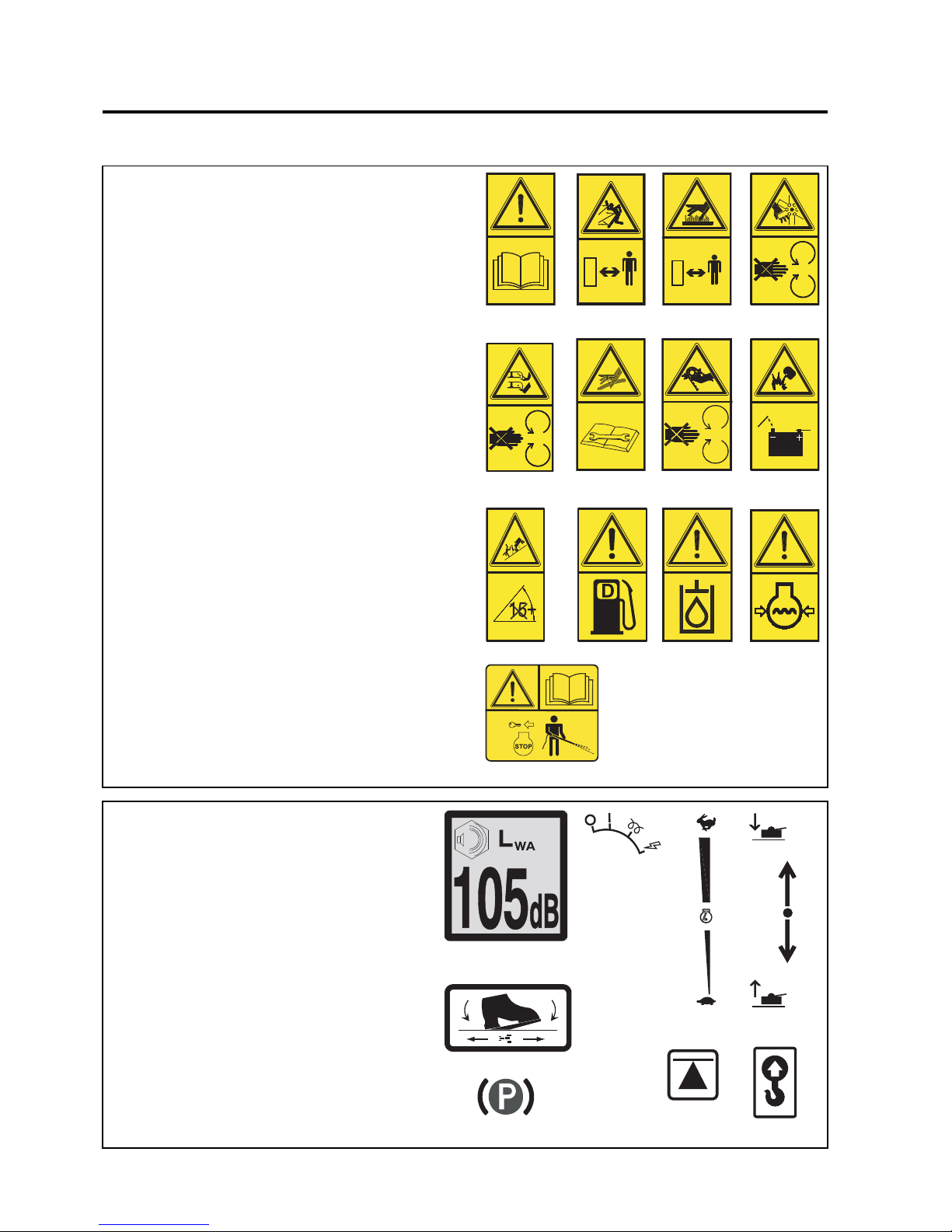
5.2 INSTRUCTION DECALS EC
Description
A. Maximum Sound Power Level
B. Ignition Switch
C. Throttle Control
D. Cutting Unit Lift
E. Fwd/Rev Traction Pedal
F. Weight Transfer
G. Parking Brake
H. Jacking Point
J. Slinging Point
ABCD
E
FG H
J
KLM
A
E
B
G
F
TC
C
D
H
J
5.1 SAFETY DECALS EC
A. 009034910 Read Operator's Manual.
B. 009034890 Keep a Safe Distance from the
Machine.
C. 009034920 Stay Clear of Hot Surfaces.
D. 009034880 Do Not Open or Remove Safety
Shields While the Engine is
Running.
E. 009034940 Caution Rotating Blades.
F. 009034930 Avoid Fluid Escaping Under
Pressure. Consult Technical
Manual for Service Procedures.
G. 009034900 Do Not Remove Safety Shields
While Engine is Running.
H. 009114100 Danger of Explosion if the
Battery Terminals are Short
Circuited.
J. 009114160 Maximum permissible working
slope.
K. 4133706 Caution Diesel Fuel
L. 4133705 Caution Hydraulic Oil
M. 4118415 Caution Engine Coolant under
Pressure
N. 4153197 Caution, Stop Engine & Remove
the Starter Key Before Pressure
Washing
4153197
N
Page 15
en-15
JACOBSEN AR3
SAFETY, OPERATORS & MAINTENANCE MANUAL
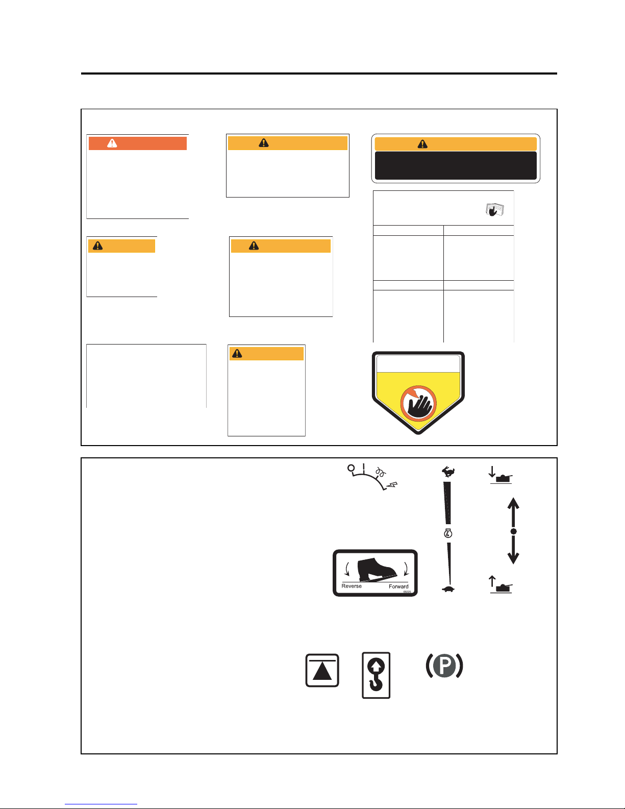
5.3 SAFETY DECALS USA
5.4 INSTRUCTION DECALS USA
A. Ignition Switch
B. Throttle Control
C. Cutting Unit Lift
D. Fwd/Rev Traction Pedal
E. Weight Transfer
F. Parking Brake
G. Jacking Point
H. Slinging Point
Description
D
B
C
5 DECALS
A
E
TC
F
G
H
ADVERTENCIA
Leer el manual del operador. No permitir que
personas no capacitadas para ello usen la
maquina.
Mantener los protectores en su lugar y sus
tornillos debidamente fijados.
Antes de limpiar, ajustar o reparar este
equipo, desengranar todas los mandos, aplicar
el freno de estacionamiento y apagar el motor.
Mantener las manos, los pies y la ropa
alejados de las piezas en movimiento.
No conducir como pasajero ni llevar pasajeros
en máquinas sin asiento para ello.
Mantener a las demás personas alejadas
durante el funcionamiento de la máquina.
Si no sabe leer inglés, solictarle a otra persona
que le lea y explique el contenido de las
etiquetas y del manual de le maquina.
1.
2.
3.
4.
5.
6.
7.
340830
WARNING
Read operator’s manual. Do not allow
untrained operators to use machine.
Keep shields in place and hardware
securely fastened.
Before you clean, adjust or repair this
equipment, disengage all drives, engage
parking brake and stop engine.
Keep hands, feet and clothing away
from moving parts.
Never carry passengers.
Keep bystanders away.
1.
2.
3.
4.
5.
6.
361854
WARNING
To prevent serious injury
never disconnect or tamper
with the seat switch.
Read manual for more information.
365339
WARNING
TO PREVENT POSSIBLE INJURY TO YOU OR OTHERS,
DO NOT OPERATE THIS UNIT WITH GUARD REMOVED
521720
DANGER
Always connect the black ground (-)
cable last and remove it first.
Keep sparks and flames away, and
avoid contact with acid.
Connect positive (+) terminal to
positive (+) terminal.
Connect negative (-) terminal on good
battery to frame of vehicle that
has dead battery.
To avoid injury when working with battery
1.
2.
To avoid injury when jumping battery
1.
2.
3001435
IMPORTANT
This machine uses GreensCare 68,
a biodegradable hydraulic fluid.
(Order 5003103 for 5 gal. pail)
Use of 10W30 is an approved
alternate fluid.
Use will compromise all
biodegradable properties of
GreensCare 68 hydraulic fluid.
4108880
1.
2.
3.
4.
5.
6.
7.
Parking Brake..............On
Traction Pedal......Neutral
Mower Switch..............Off
Throttle.......................Half
Ignition.........................On
Glow Plug Light..........Off
Ignition.....................Start
1.
2.
3.
4.
5.
6.
Traction Pedal......Neutral
Mower Switch..............Off
Parking Brake..............On
Throttle.....................Slow
Ignition........................Off
Remove Key
1.
2.
3.
4.
5.
6.
Follow “To Start”
instructions
Mower Switch..............Off
Cutting Units...........Raise
Parking Brake.............Off
Throttle......................Fast
Slowly depress
traction pedal
1.
2.
3.
4.
5.
6.
Follow “To Start”
instructions
Throttle......................Fast
Mower Switch...........Mow
Parking Brake.............Off
Cutting Units.........Lower
Slowly depress
traction pedal
4124445
To Drive / Transport
To Start
To M ow
To Stop / Park
READ MANUAL BEFORE OPERATING
REPLACEMENT MANUAL AVAILABLE FROM:
JACOBSEN TEXTRON - CHARLOTTE, NC
OPERATION
WARNING
Fit roll over protective
structure before using
this machine on slopes
greater than 10°.
Do not use on slopes
greater than 15°.
Keep bystanders away
•
•
•
4139680
KEEP HANDS AND FEET AWAY
DANGER
DANGER
835892
Page 16
en-16
JACOBSEN AR3
SAFETY, OPERATORS & MAINTENANCE MANUAL
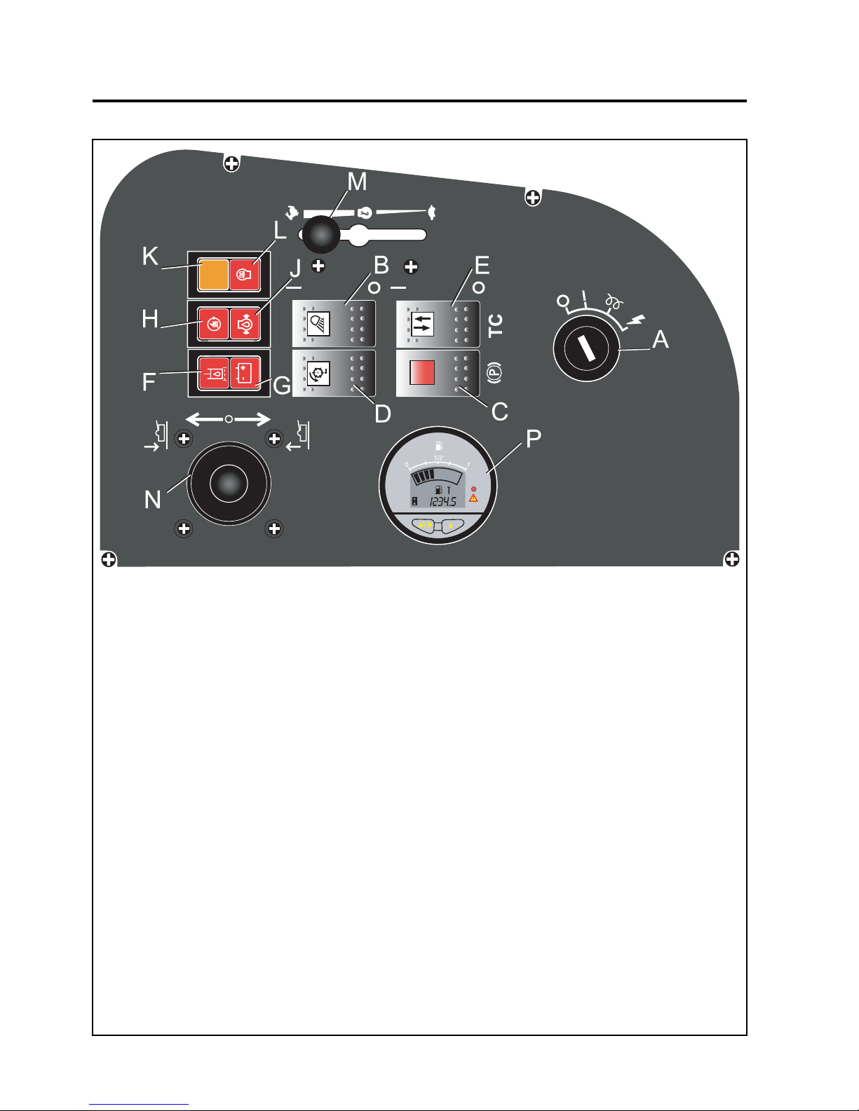
6.1 INSTRUMENT PANEL
A: Starter Key Switch
B: Workin g Light Switch
C: Parking Brake Switch
D: Cutter Switch
E: Weight Transfer Switch
F: Blocked Hydraulic Filter Warning Lamp
G: Charge Warning Lamp
H: Engine Coolant Temperature Warning Lamp
J: Engine Oil Pressure Warning Lamp
K: Control Module Fault Warning Lamp
L: Engine Preheat Indicator Lamp
M: Throttle Control Lever
6CONTROLS
N: Joystick Unit Lift/Lower Control
P: Multi-Function Gauge
Page 17
en-17
JACOBSEN AR3
SAFETY, OPERATORS & MAINTENANCE MANUAL
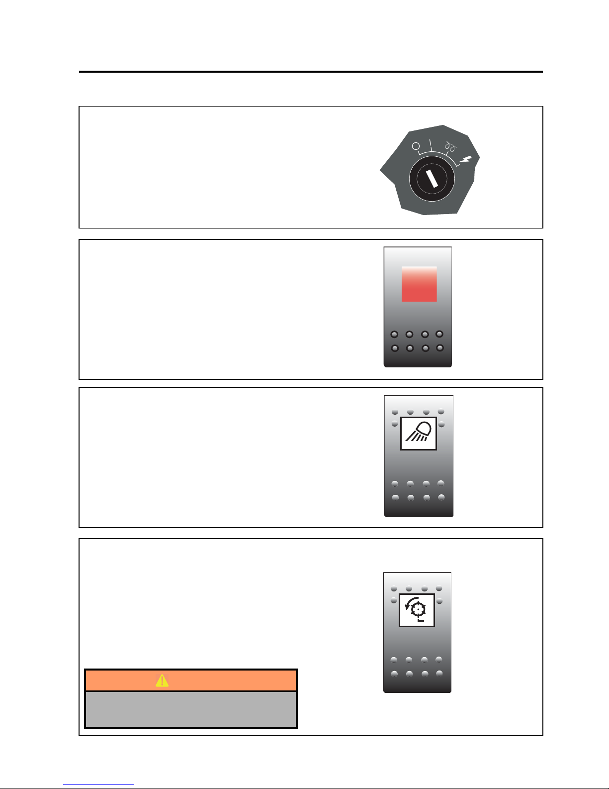
6.1A STARTER KEY SWITCH
The starter key (A) should be turned clockwise to the
'pre-heat' (No. 2) position to heat the glowplugs when
the green warning lamp goes out, on warning lamp
display module, turn the starter key clockwise to the
'start' (No. 3) position to start the engine. After
starting, the key should be released and allowed to
return automatically to the 'on' (No. 1) position for
normal running.
6.1D CUTTING UNIT SWITCH
To commence cutting ensure speed limiter is in mow
position and the units have been lowered.
Push bottom of the rocker switch and move joystick
towards the lower position.
To stop cutter unit rotation push top of rocker switch.
(Cutting units stop rotating automatically when
raised.)
WARNING
If units are lowered with the cutting switch
engaged they will start immediately.
6 CONTROLS
6.1B PARKING BRAKES
When the engine is running the Parking brake is
applied by sliding back the orange button on the
rocker and depressing the switch on the control
panel.
When the engine is switch off the parking brake is
automatically applied.
To release the parking brake depress the opposite
end of the rocker switch.
DO NOT apply the brake when the machine is
moving.
6.1C WORKING LIGHT SWITCH
Push bottom of the rocker switch to turn light on.
When the working light is on the switch is illuminated.
Push top of rocker switch to turn working light off.
Page 18
en-18
JACOBSEN AR3
SAFETY, OPERATORS & MAINTENANCE MANUAL
6CONTROLS
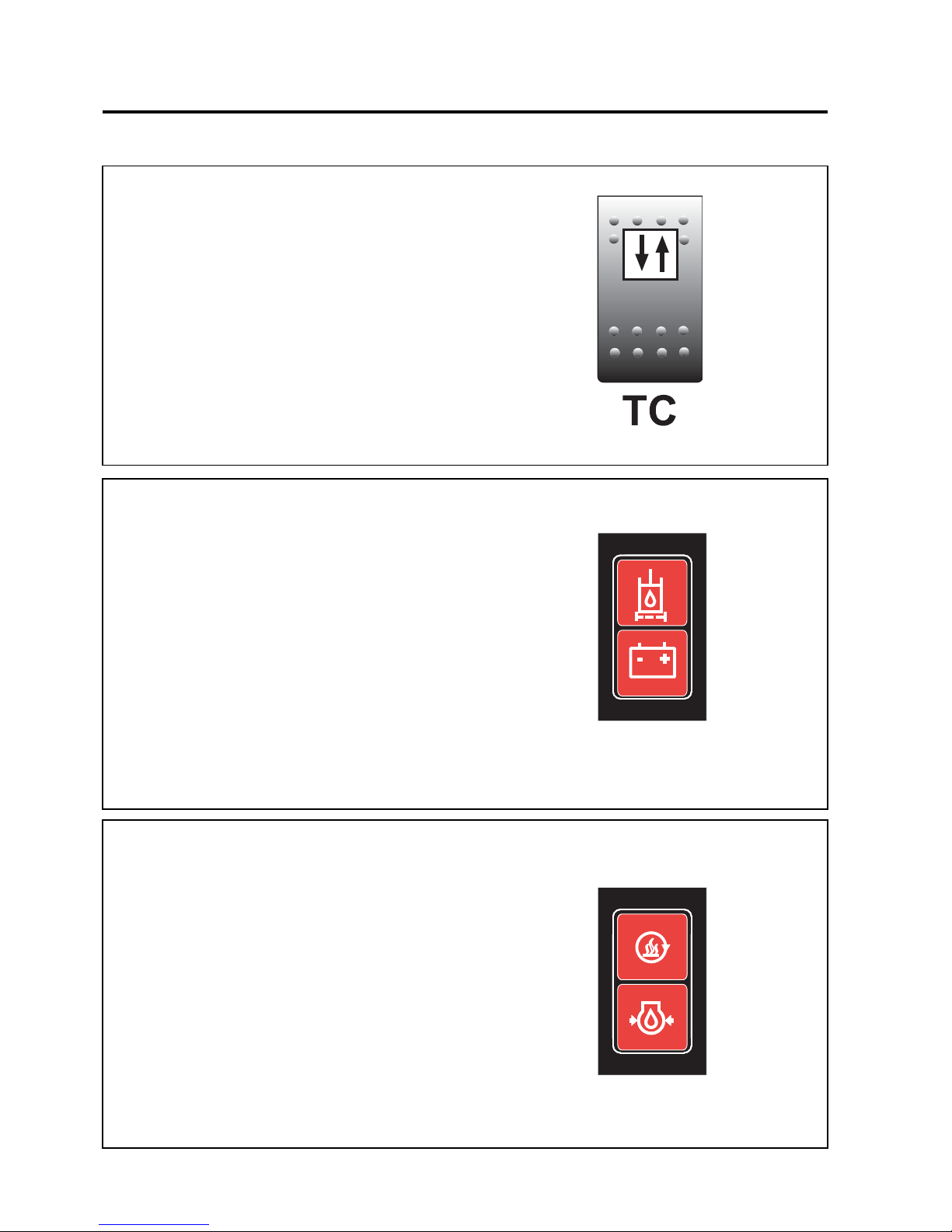
6.1E WEIGHT TRANSFER SWITCH
This switch allows the operator to transfer weight off
the cutting units onto the machine. this gives the
machine better traction.
Depress the rocker switch to transfer weight off the
cutting units, the warning lamp will illuminate.
When the switch is in the off position weight is
transferred back onto the units, the warning lamp will
go out.
Note: The weight transfer comes factory set. If
adjustment is required this can be done by using an
allen key to adjust the valve under the left hand side
of the foot plate. See section 9.2
6.1J. ENGINE OIL PRESSURE WARNING LAMP
Colour red, on when the ignition is switched on, and
will go out once the engine has started. If the light
comes on while the engine is running - STOP
IMMEDIATELY as this indicates that the engine oil
pressure is too low. Check the level of oil in the sump
and top up as necessary. Check the oil pressure
sender switch. Continued operation may cause
extensive damage to the engine.
6.1G. CHARGING WARNING LAMP
Colour red, on when ignition is switched on and will
go out when the engine is started. If the light comes
on while the engine is running, the fan belt may be
slipping or broken or a fault in the electrical system
is indicated and should be investigated. STOP
IMMEDIATELY.
6.1F BLOCKED HYDRAULIC FILTER
INDICATOR LAMP.
Monitors Hydraulic filter condition. Coloured red,
Illuminates prior to filter bypass valve operating, when
illuminated filter r equires ch anging. T he lamp shou ld
illuminate while the engine is preheating as a test. It
is not unusual for the lamp to stay light for up to 3
minutes after a very cold start. But should not stay on
for longer than 5 minutes during operation.
6.1H ENGINE COOLANT TEMPERATURE
WARNING LAMP
Colour red, on when the engine coolant temperature
reaches a preset level (Note: an audable alarm is
also activated). If the lamp comes on and alarm
sounds bring the machine to a stop, disengage the
cutting units, apply the parking brake and stop the
engine.
Page 19
en-19
JACOBSEN AR3
SAFETY, OPERATORS & MAINTENANCE MANUAL
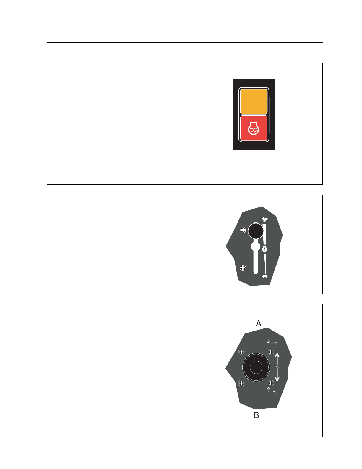
6.1M THROTTLE CONTROL LEVER
The lever should be moved away from the operator
to increase the engine speed and towards the
operator to decrease the engine speed.
NOTE: Engine should be used at full speed.
6.1N JOYSTICK UNIT LIFT/LOWER CONTROL
The joystick can be operated in 2 directions (single
Axis) A, B.
A One touch lower. Lower all cutting units.
B Raise all cutt ing units.
(Needs to be held at position B for lifting
units into transport position)
6 CONTROLS
6.1L ENGINE PREHEAT INDICATOR LAMP
Colour red, on when the ignition switch is turned
clockwise to the pre-heat position. Once the lamp
goes out the engine can be started.
6.1K SAFETY MO DULE MALFUNCTION
Colour orange, on when the safety module
malfunctions. Stop machine and turn off ignition
leave for a few seconds and switch ignition back on.
If the indicator lamp is still on, contact your Dealer.
Page 20
en-20
JACOBSEN AR3
SAFETY, OPERATORS & MAINTENANCE MANUAL
6CONTROLS
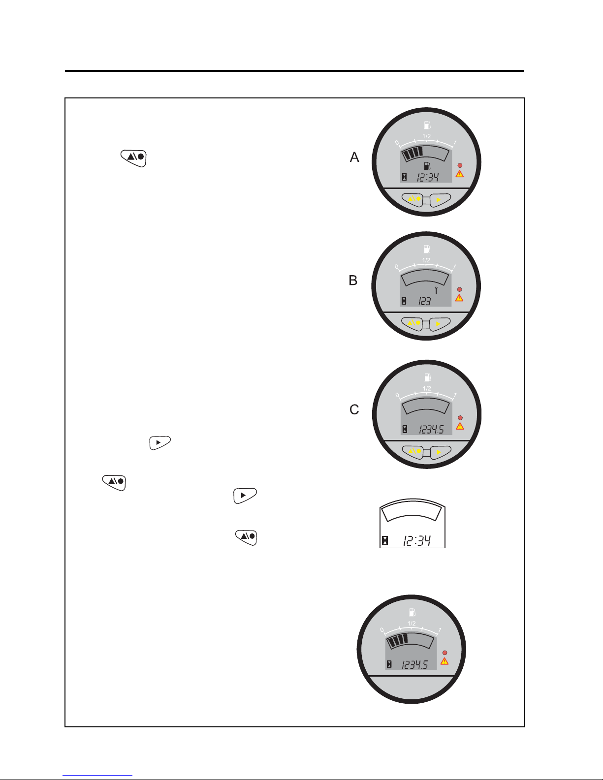
6.1P MULTI-FUNCTION GAUGE(Prior to s/n
GX000396)
The various functions can be selected using the left
hand button
The fuel level is displayed on a digital bargraph in the
upper segment of the display. The clock, time to service
and hourmeter is displayed in the lower segment of the
display in numeric format.
Low fuel level
The bargraph, black fuel pump symbol and red LED
above warning triangle will flash
Service Required
The black spanner symbol and red LED above warning
triangle will flash
A. Clock Function / Fuel Gauge
Function
B. Time To Service Function
C. Total Hours Function
Setting the Time-Of-Day Clock
The display will flash the two “HOURS” digits. Press
the right button to increment by one hour, or
hold the button to increment continuosly. When the
desired number of hours is reached, press the left
button once. The display will flash the two
“minutes” digits. Press the right button to
increment by onr minute or hold the button to
increment continusly. When the desired number of
minutes is reached, press the left button once.
MULTI-FUNCTION GAUGE(From s/n GX000396)
The gauge has no adjusting or setting buttons and
displays fuel level and total hours
Page 21
en-21
JACOBSEN AR3
SAFETY, OPERATORS & MAINTENANCE MANUAL
6 CONTROLS
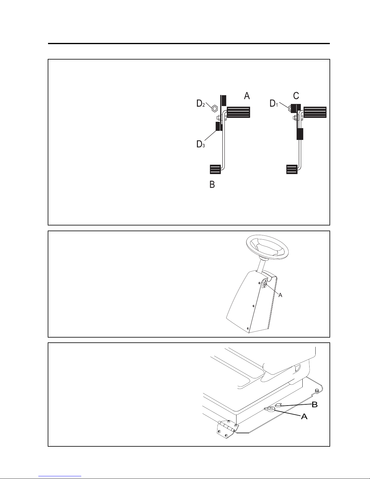
6.2 TRACTION FOOT PEDAL
A. Forward Travel (Traction Pedal)
Press front of pedal down for forward travel. Release
pedal to slow tractor and stop. Do not press traction
pedal when parking brake is set and parking brake
light (W) is lit.
B. Reverse Travel (Traction Pedal)
Press rear of pedal down for reverse travel. Release
pedal to slow tractor and stop. Allow tractor to come
to a complete stop before reversing direction. Do not
press traction pedal when parking brake is set and
parking brake light (W) is lit.
C. Mow Speed Stop
Limits forward speed while mowing. To operate at
lower travel speed while mowing, rotate lever so it
contacts stop screw (D1) on floor board when forward
travel pedal is pressed. To travel at full speed, set
lever in position shown (D3). Stop screw (D2) can be
adjusted to set specific mow speeds.
6.3 STEERING TILT CONTROL
Pull lever A up to release steering column. Tilt column
up or down to position desired. Release lever A to
lock steering column in place
6.4 Power Outlet
The Auxiliary Power Outlets are situated on the left
hand side of the seat on the seat plate
A Automotive 12V Power Outlet (Cigar Lighter)
B Accessory 12V Power Outlet
Page 22
en-22
JACOBSEN AR3
SAFETY, OPERATORS & MAINTENANCE MANUAL
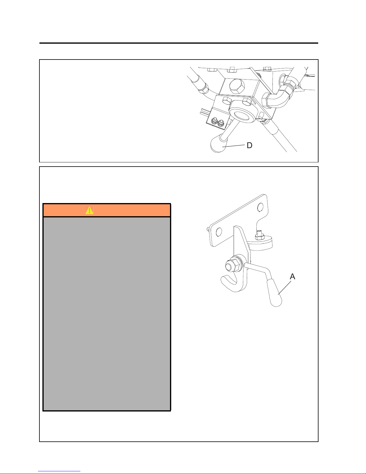
6.5 PARKING BRAKE RELEASE VALVE
The Parking Brake Release Valve is situated under
the Operators Platform, close to the front axle. It is
used to release the parking brake when the engine
is not running
The Parking brake can be released by rotating the
lever D to the right ( when viewed from the front of
the machine) and turning the steering wheel
clockwise until resistance is felt
6CONTROLS
6.6 TRANSPORT LATCHES (Optional)
Transport latches A are fitted for the front cutting
units.
WARNING
Cutting Unit Transport Latches are a
Secondary Safety Devise.
When Transporting the machine the Cutting
units should be held in the Transport position
on the Hydraulics with the Transport Latches
Engaged.
1. Park the machine on level ground.
2. Whilst seated in the driving position with the
engine at operating speed raise the cutting
units fully by operating lift joystick, return the
joystick to the neutral position.
DO NOT move the joystick into the lower
position.
3. Disengage drives, stop the engine and make
sure all moving parts are stationary. Apply
brakes and remove the starter key.
4. Transport latches can now be engaged or
released.
Before releasing transport latches it is
important that all cutting units are fully
raised.
Page 23

en-23
JACOBSEN AR3
SAFETY, OPERATORS & MAINTENANCE MANUAL
7 OPERATION
7.1 DAILY INSPECTION
1. Perform a visual inspection of the entire unit, look for signs of wear, loose hardware and missing or
damaged components. Check for fuel and oil leaks to ensure connections are tight and hoses and
tubes are in good condition.
2. Check the fuel supply, radiator coolant level, crankcase oil level and air cleaner is clean. All fluids
must be at the full mark with the engine cold.
3. Make sure all cutting units are adjusted to the same height of cut.
4. Check all tyres for proper inflation.
5. Test the operator presence and safety interlock system.
CAUTION
The daily inspection should be performed only
when the engine is off and all fluids are cold.
Lower implements to the ground, engage
parking brake, stop engine and remove ignition
key.
Page 24
en-24
JACOBSEN AR3
SAFETY, OPERATORS & MAINTENANCE MANUAL
7OPERATION
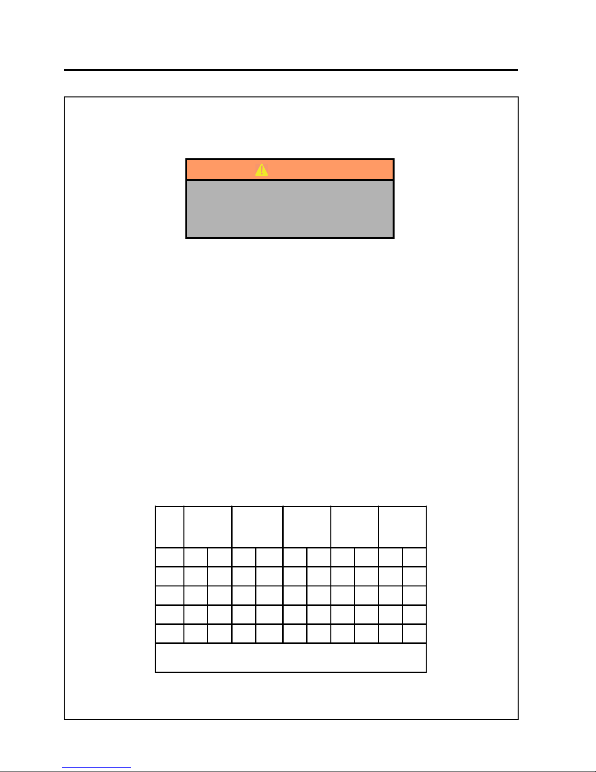
7.2 OPERATOR PRESENCE AND SAFETY INTERLOCK SYSTEM
1. The operator presence & safety interlock system prevents the engine from starting unless the parking
brake is on, and the mowing device is switched off. The system also stops the engine if the operator
leaves the seat with the mowing device engaged or the neutral latch depressed.
2. Perform each of the following tests to ensure the operator presence & safety interlock system is
functioning properly. Stop the test and have the system inspected and repaired if any of the tests fail
as listed below:
• The engine does not start in test 1;
• The engine does start during tests 2 or 3.
• The engine continues to run during test 4.
3. Refer t o t h e char t be l ow fo r ea ch t est an d f o ll ow t h e ch e ck () marks across the chart. Shut engine
off between each test.
Test 1: Represents normal starting procedure. The operator is seated, parking brake is on, the
operators feet are off the pedals and the mower engagement device is off. The engine should start.
Test 2: The engine must not start if the mower engage device is on.
Test 3: The engine must not start if the Traction Pedal is depressed.
Test 4: Start the engine in the normal manner, then turn mower engage device on and lift your weight
off the seat.
WARNING
Never operate the equipment with the
operator presence & safety interlock
system disengaged or malfunctioning. Do
not disconnect or bypass any switch.
Test
Operator
Seated
Parking
Brake
Switch
Mower
Switch
Traction
Pedal in
Neutal
Engine
Starts
Y es No Y es No On Off Yes No Yes No
1
2
3
4
Li ft your weight off seat. The cutting units must stop rotating
within se ven (7) se c onds
Page 25
en-25
JACOBSEN AR3
SAFETY, OPERATORS & MAINTENANCE MANUAL
7 OPERATION
7.3 OPERATING PROCEDURE
1. Under no circumstances should the engine be started without the operator seated on the tractor.
2. Do not operate tractor or attachments with loose, damaged or missing components. Whenever possible
mow when grass is dry
3. First mow in a test area to become thoroughly familiar with the operation of the tractor and control levers.
4. Study the area to determine the best and safest operating procedure. Consider the height of the grass,
type of terrain, and condition of the surface. Each condition will require certain adjustments or
precautions.
5. Never direct discharge of material toward bystanders, nor allow anyone near the machine while in
operation. The owner/operator is responsible for injuries inflicted to bystanders and/or damage to their
property.
6. Use discretion when mowing near gravel areas (roadway, parking areas, cart paths, etc.). Stones
discharged from the implement may cause serious injuries to bystanders and/or damage the
equipment.
7. Disengage the drive motors and raise the implements when crossing paths or roads. Look out for traffic.
8. Stop and inspect the equipment for damage immediately after striking an obstruction or if the machine
begins to vibrate abnormally. Have the equipment repaired before resuming operation.
CAUTION
To help prevent injury, always wear safety
glasses, leather work shoes or boots, a hard
hat and ear protection.
CAUTION
Pick up all debris you can find before mowing.
Enter a new area cautiously Always operate at
speeds that allow you to have complete control
of the tractor
WARNING
Before you clean, adjust, or repair this
equipment, always disengage all drives,
lower implements to the ground, engage
parking brake, stop engine and remove key
from ignition switch to prevent injuries.
Page 26
en-26
JACOBSEN AR3
SAFETY, OPERATORS & MAINTENANCE MANUAL
9. Slow down and use extra care on hillsides. Read Section 3.7. Use caution when operating near drop
off points.
10. Never use your hands to clean cutting units. Use a brush to remove grass clippings from blades.
Blades are extremely sharp and can cause serious injuries
WARNING
DO NOT USE ON SLOPES GREATER THAN
15°
7OPERATION
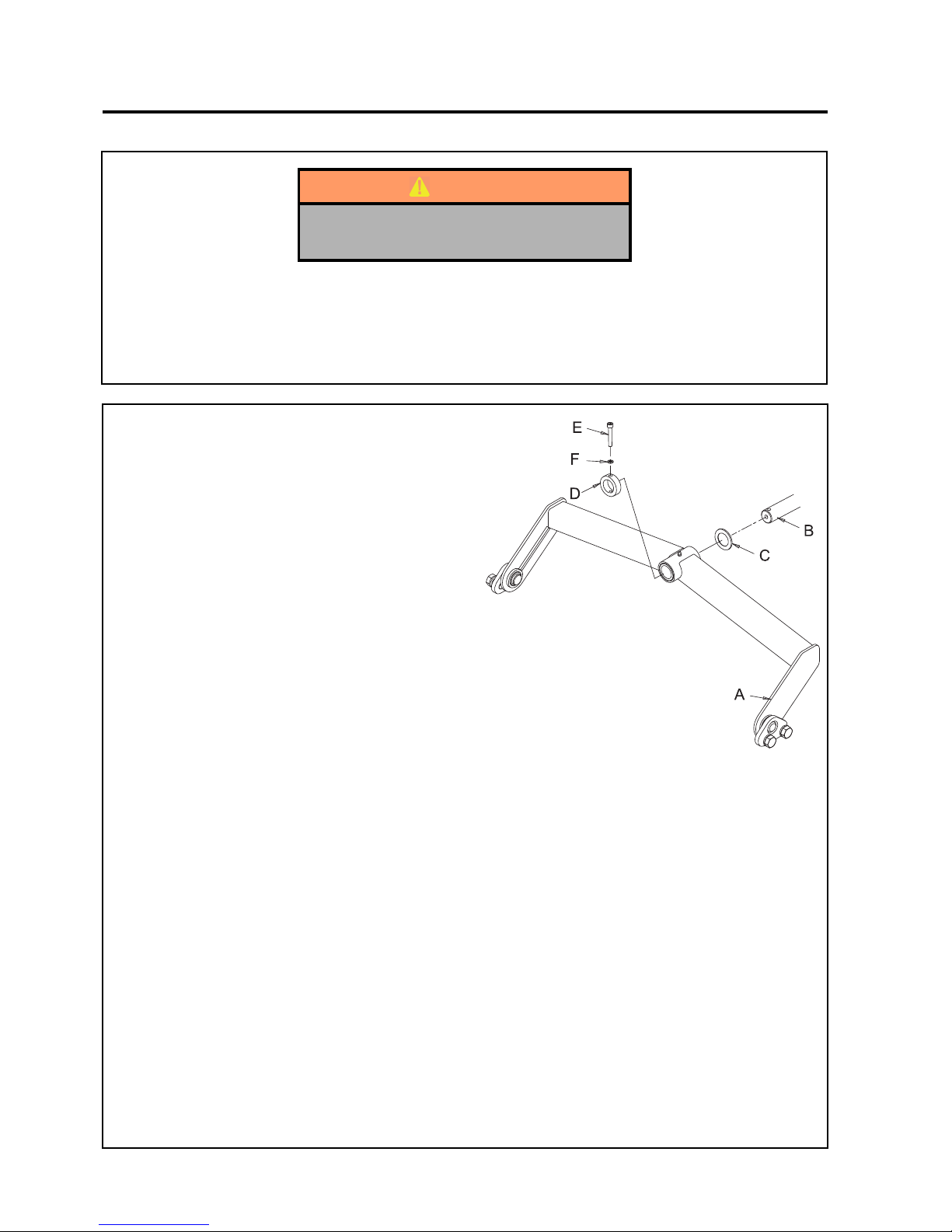
7.4 FITTING THE CUTTING UNITS TO THE
MACHINE
1. With the lift arms in the lowered position
slide the cutting unit pivot yoke (A) up to the
mounting shaft (B).
2. Fit Washer (C) to shaft (B).
3. Smear bushes with grease.
4. Align the shaft (B) with the cutting unit pivot
yoke (A).
5. Slide pivot yoke (A) on to the mounting shaft
(B).
6. Fit Collar (D) to mounting shaft (B).
7. Secure with cap screw (E) and lockwasher
(F).
Page 27

en-27
JACOBSEN AR3
SAFETY, OPERATORS & MAINTENANCE MANUAL
7 OPERATION
OPERATION OF THE MACHINE
Read the Safety Instructions.
BEFORE OPERATING FOR THE FIRST TIME
• Check and adjust tyre pressure, if
necessary, section 4 Specification.
• Add diesel fuel to tank if neccesary.
• Check engine oil and top-up, if necessary.
• Check radiator coolant and top-up, if
necessary (50% antifreeze solution).
• Make sure you understand the information
contained in the previous sections.
7.5 STARTING THE ENGINE
The following procedure is for starting cold engines.
1. Ensure the FWD/REV pedal is in the neutral
position, the mow switch is off, the throttle
setting is in a mid position and the parking
brake is applied.
2. Turn the ignition switch to position No.2 and
hold until the glow plug light goes off (5-10
sec.)
3. Turn ignition key fully clockwise to the start
position and operate the starter motor until
the engine starts (This should only take a
few seconds)
4. When the engine starts, release the key
immediately and it will return to the RUN
position.
5. If the engine does not start, preheat the
glow plugs and try again.
NOTES:
• Warm engine - When the engine is warm
because of surrounding temperature or
recent operation, step No.2 of the cold
engine starting procedure may be omitted
(no need to preheat glow plugs).
• If the engine fails to start after two attempts
(with preheat if necessary), wait 20
seconds and try again.
• The starter motor should never be run
continuously for longer than 30 seconds or
it may fail.
7.6 DRIVING
• Release brake - Make sure the parking
brake is released before attempting to go
forward or reverse.
• Forward - Gently depress the top of the
FWD/REV foot pedal to reach desired
ground speed.
• Reverse - Gently depress the bottom of the
FWD/REV foot pedal to reach desired
ground speed.
• To stop - Gently return the FWD/REV foot
pedal to the neutral position.
• To hold the vehicle stationary on a slope it
may be necessary to apply a certain
amount of reverse traction.
NOTES:
• Use complete foot to operate both forward
and reverse.
NOTES:
• Use complete foot to operate both forward
and reverse.
• Do not move pedal suddenly–always
operate slowly and smoothly. Never move
pedal violently from forward to reverse or
vice versa.
• Always keep foot firmly on the foot pedal–
a too relaxed foot control may result in a
jerky motion.
7.7 MOWING
1. Lower the units with the cutting unit lift/
lower control.
2. Ensure speed limiter is in mow position.
3. Engage the cutting mechanism by pushing
on the lower half of cutting unit switch.
4. Release the parking brake and begin
driving forward.
NOTE: Always set the throttle to full engine revs.
for mowing, even when the grass is heavy.
When the engine is labouring, reduce
forward speed by easing back on the FWD/
REV foot pedal.
7.8 TO STOP THE ENGINE
1. Disengage drive to the cutting units with the
cutting unit switch.
2. Remove foot from the FWD/REV pedal.
3. Set the parking brake.
3. Move the throttle control lever to the SLOW
position.
4. Turn the ignition key to OFF.
Page 28
en-28
JACOBSEN AR3
SAFETY, OPERATORS & MAINTENANCE MANUAL
7OPERATION
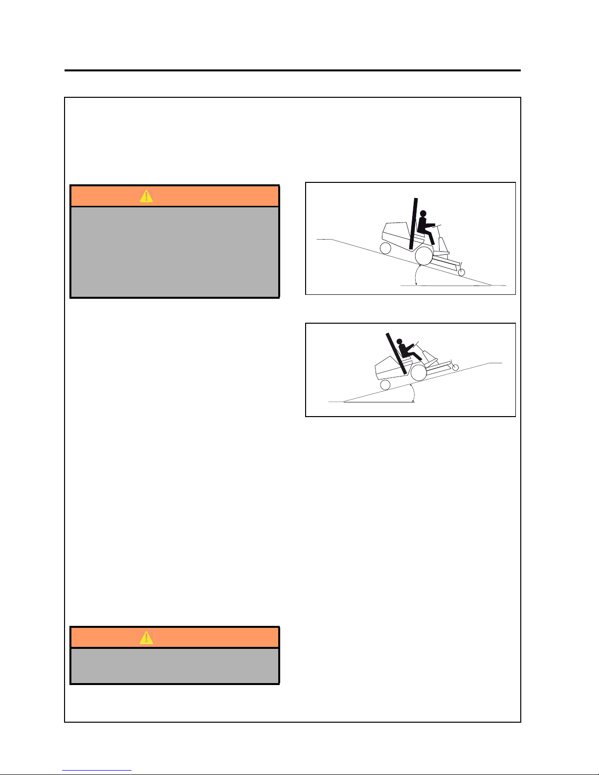
15° Maximum
15° Maximum
7.9 MOWING ON SLOPES
The mower has been designed for good traction and stability under normal mowing conditions. Use caution
when operating on slopes, especially when the grass is wet. Wet grass reduces traction and steering
control.WARNING
A = Maximum Allowable Slope
.
A = Maximum Allowable Slope
.
Degrees are shown to the nearest 1/4”.
General slope of roadway embankment - 45°
Steepest grass area - 31°
Slope of average roof - 19-1/4°
2nd class highway maximum grade 4-1/2°
Toll road or freeway - 1-3/4°
1. Always mow with the engine at full throttle,
control forward speed using traction foot pedal
to maintain proper cutting.
2. Use weight transfer control as required to
improve weig ht distribution between decks
and mower.
3. If the mower tends to slide or the tyres begin
to mark the turf, angle mower into a less steep
slope until traction is regained or tyre marking
stops.
4. If mower continues to slide or mark the turf,
the slope is too steep for safe operation. Do
not make another attempt to climb, and back
down slowly.
5. When descending a steep slope, always lower
implements to the ground to reduce the risk of
mower overturning.
Correct tyre pressure is essential for maximum
traction.
See Specification
WARNING
To m inimize the possibility of overturning,
the safest method for operating on hills
and terraces is to travel up and down the
face of the slope (vertically), not across the
face (horizontally). Avoid unnecessary
turns, travel at reduced speeds, and stay
alert for hidden hazards.°
WARNING
DO NOT USE ON SLOPES GREATER THAN
15°
Page 29
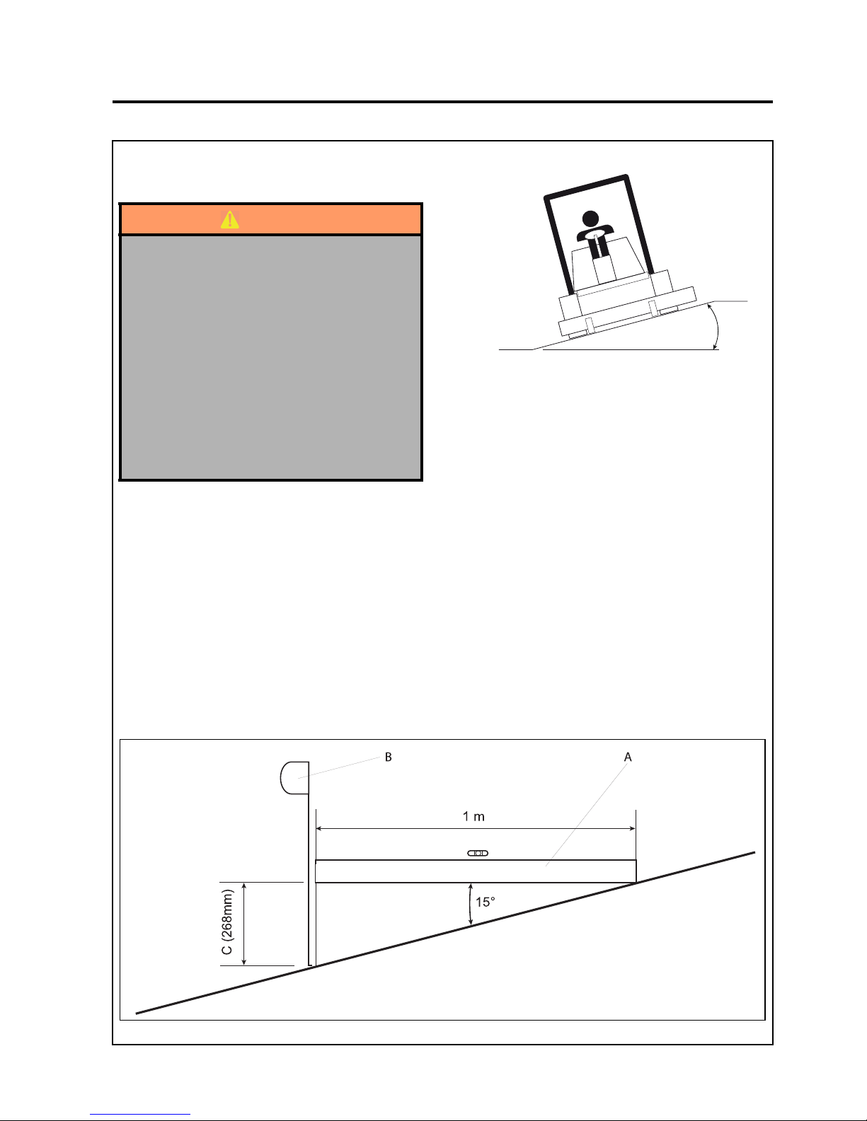
en-29
JACOBSEN AR3
SAFETY, OPERATORS & MAINTENANCE MANUAL
7 OPERATION
15° Maximum
A = Maximum Allowable Slope
.
How to calculate a slope
Tools:
Spirt level 1 metre long.
Tape measure.
With the spirt level (A) positioned horizontally measure the distance (C) with tape measure (B) Use the chart to
calculate either the slope angle or the% grade D of the slope.
If it is necessary to mow across a short slope, ensure
the right hand cutting unit is the lowest.
WARNING
When the machine is being used, whether
cutting grass or not, on slopes, the ROPS
frame should be deployed and the seat belt
used.
This rationale is based on the fact that a seat
belt must be worn with a ROPS to comply with
the Machiney Directive 2006/4 2/EC sections
3.2.2, Seating & 3.4.3, Rollover
Ransomes Jacobsen Limited recommends
that a local risk assess ment is completed by
the owner/user of the machine to determine
the risks associated with working on slopes.
Page 30
en-30
JACOBSEN AR3
SAFETY, OPERATORS & MAINTENANCE MANUAL
7OPERATION
Use Eit her of t hese columns but not both The res ult of what you are measuring
Height C in inches
measured with a 1 yard
horizontal edge A
Height C in millimete r s
measured with a 1
metre horizontal edge
A
Slope Angle D
measured in Degrees
Slope Angle D
measured in G rade%
34.88.3
100 5.7 10.0
150 8.5 15.0
6 9.5 16.7
200 11.3 20.0
7.5 11.8 20.8
225 12.7 22.5
9 250 14.0 25.0
275 15.4 27.5
10 15.5 27.8
300 16.7 30.0
11 17.0 30.6
325 18.0 32.5
12 18.4 33.3
350 19.3 35.0
13 19.9 36.1
375 20.6 37.5
14 21.3 38.9
400 21.8 40.0
15 22.6 41.7
425 23.0 42.5
16 24.0 44.4
475 25.4 47.5
18 500 26.6 50.0
20 29.1 55.6
600 31.0 60.0
25 34.8 69.4
800 38.7 80.0
30 39.8 83.3
900 42.0 90.0
36 1000 45.0 100.0
Page 31
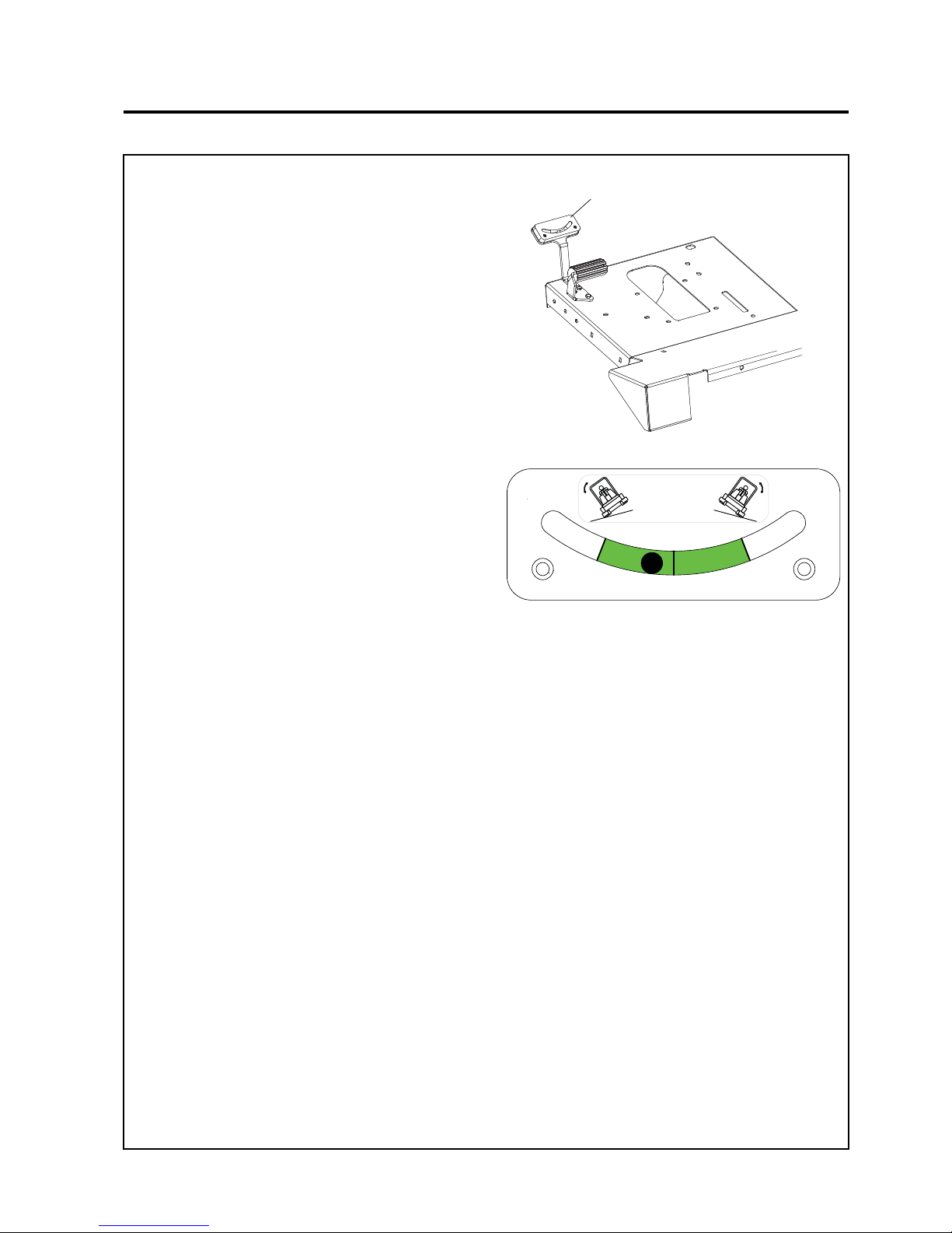
en-31
JACOBSEN AR3
SAFETY, OPERATORS & MAINTENANCE MANUAL
7 OPERATION
A
Use of Inclinometer when fitted.
The Inclinometer (A) is located on the left hand side
of the footplate forward of the foot rest.
When working on slopes the device indicates when
the machine is working within stability limits (the ball
is within the green area).
When the ball is outside the green area this indicates
the machine is at risk of roll over.
NOTE
The Inclinometer only works on side slopes
Gauge to be
mounted leaning
backwards at 45°
Page 32

en-32
JACOBSEN AR3
SAFETY, OPERATORS & MAINTENANCE MANUAL
8 MAINTENANCE & LUBRICATION
8.1 Maintenance & Lubrication Chart
MAINTENANCE AND LUBRICATION CHART
Interval Item Section
First 50 hours
Change Engine Oil
Check Fan Belt Tension
Change Hydraulic Filter
82
8.3
8.5
Daily
10 hours
Check Engine Oil Level
Check Safety Interlock System.
Check Coolant Level
Check Hydraulic Fluid Level
Check Ty re Pr ess ur e
Check Engine Bay for Debris
8.2
7.2
8.4
8.5
4.2
8.10
Weekly
Every 50 hours
Check for Loose Components.
Check for Hydraulic Leaks.
Check Fan Belt Tension
Check Air Filter Tell Tail Indicator *
8.10
8.10
8.3
8.8
Every 250 hours
Change Engine Oil and Oil Filter
8.2
End of season
Every 1000 hours
Check Battery Condition.
Change Hydraulic Oil & Filter
Change Air Filter Element *
Replace Fuel Filters
Change Hydraulic Oil and Filter
Drain and Clean Fuel Tank
Drain and Replace Engine Coolant
8.9
8.2
8.8
8.7
8.5
8.7
8.4
Lubricate all Grease fittings weekly (see diagram)
* Check more offten in dusty conditions
IMPORTANT
Refer to Engine Manufacturers Manual for Additinal Engine Maintenance Procedures
FLUID REQUIREMENTS
Quantity Type
A Engine Oil (with filter) 5.1 litres (1.35 US gals) 10W 30
B Hydraulic Oil (with filter) 37.9 litres (10 US gals) Greenscare 46 (ISO VG 46) Bio
Degradable Oil
C Radiator Coolant 5.2 litres (1.37 US gals) 50% Anti-Freeze
D Fuel 45.4 litres (12 US gals) No 2-D (ASTM D975) Diesel
Page 33
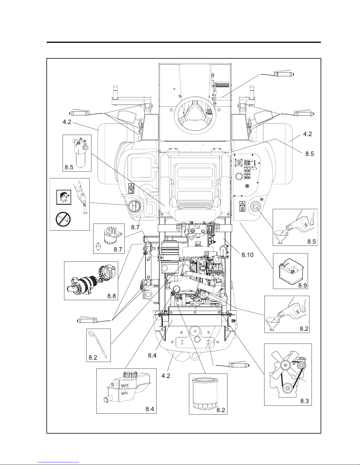
en-33
JACOBSEN AR3
SAFETY, OPERATORS & MAINTENANCE MANUAL
8 MAINTENANCE & LUBRICATION
Page 34
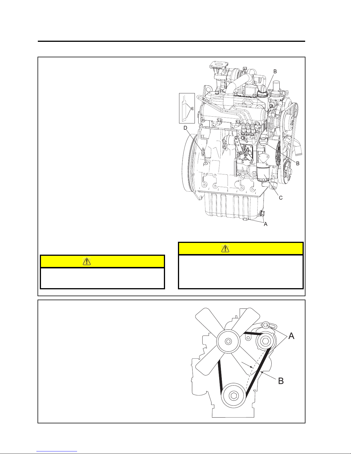
en-34
JACOBSEN AR3
SAFETY, OPERATORS & MAINTENANCE MANUAL
8.2 ENGINE LUBRICATION
Check Engine Oil Level
Check the engine oil level before starting or more
than five minutes after stopping the engine.
(a) With the machine on level ground, remove
the dipstick, wipe it clean and replace.
(b) Take the dipstick out again, and check the
oil level. It should be between level marks
(E) on dipstick.
Change Engine Oil.
(a) Warm up the engine first and then shut it
off. Remove oil drain plug (A) from the
bottom of the crankcase and wipe it off.
(b) Drain engine oil in to a suitable container.
(c) Replace the drain plug (A) and fill engine
with the correct quantity & grade of oil
through one of the fillers (B).
Change Engine Oil Filter
(a) Remove single-unit cartridge (C)
(b) Collect engine oil in a suitable container.
(c) Clean area on crankcase.
(d) Apply thin coat of oil to cartridge gasket
before installing.
(e) Tighten filter by hand only.
(f) Check for oil leaks around the cartridge
gasket after engine is started.
CAUTION
Dispose of used engine oil in accordance with
local regulations.
8 MAINTENANCE & LUBRICATION
8.3 ENGINE: FAN BELT
Check & Adjust Fan Belt.
The fan belt is adjusted so that it has sufficient tension
to avoid undue stress on alternator bearings but does
not slip on the alternator pulley. Use the following
procedure to check the belt tension at the mid-point
of the belt between crank shaft and alternator pulleys.
1. Loosen alternator bolt (A ) and pivot bolt on the
underside of the Alternator.
2. Move the alternator to tighten or loosen the belt
so that a deflection of 7 to 9 mm is achieved at
the mid-span (B) with a load 10Kgf (98N/22lbs)
for a new belt, and 8 to 10mm for a used belt.
3. Re-tighten bolts .
CAUTION
Contact with engine oil can damage your skin.
Use gloves when working with engine oil. If
you come in contact with engine oil, wash it
off immediately.
Page 35
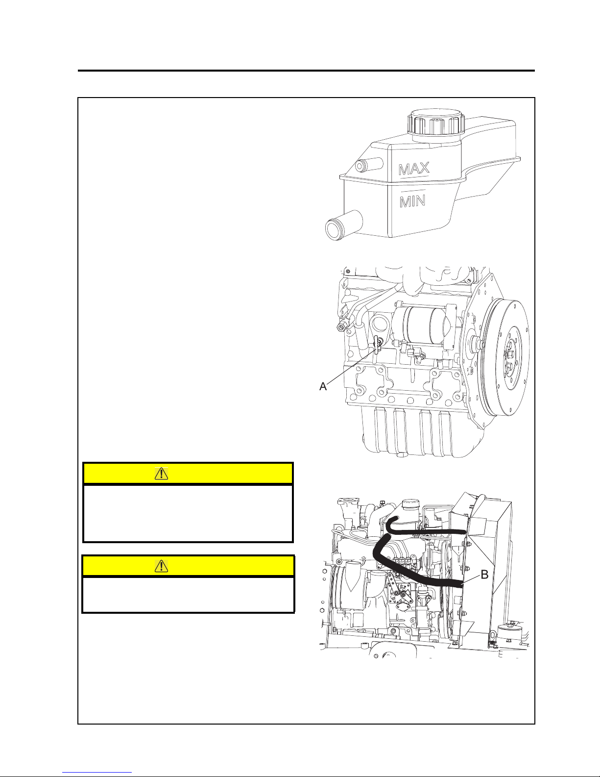
en-35
JACOBSEN AR3
SAFETY, OPERATORS & MAINTENANCE MANUAL
8.4 ENGINE COOLANT
Check Engine Coolant Level
(a) The level of coolant in the expansion tank
should be between the MAX and MIN level
indicators when cold.
(b) If t opping up is required, remo ve the plastic
cap and top up using the correct anti-freeze
mixture, see section 9.1.
(c) Replace the plastic cap when finished.
Changing Coolant
(a) To drain coolant, open cock on engine
block (A) and remove hose from radiator
(B).
(b) Close drain cock on engine block (A) and
replace hose back on to radiator. Ensure
all hose clips are tight.
(c) Refill the cooling system with the correct
anti-freeze mixture, see section 9.1. Fill
system through expansion tank.
(d) The level of coolant in the expansion tank
should be between the MAX and MIN level
indicators when cold.
(e) Run the engine for approximately 5 minutes
or until the thermostat opens.
(f) Check level of coolant in expansion tank
and top up if necessary
CAUTION
Contact with anti-freeze can damage your
skin. Use gloves when working with antifreeze. If you come in contact with antifreeze, wash it off immediately.
CAUTION
Dispose of used anti-freeze in accordance
with local regulations.
8 MAINTENANCE & LUBRICATION
Page 36
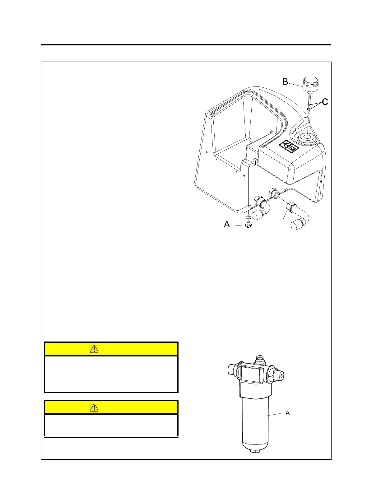
en-36
JACOBSEN AR3
SAFETY, OPERATORS & MAINTENANCE MANUAL
8 MAINTENANCE & LUBRICATION
Change Hydraulic Oil Filter
(a) Wipe filter canister (A) and housing to
remove any dirt present.
(b) Place a suitable drip tray under the filter.
(c) Unscrew filter and dispose of safely.
(d) Replace with new filter canister (A).
(e) Coat the top outside lip of the filter canister
with a thin film of oil, fill filter with clean
hydraulic fluid and refit the filter canister.
(f) Filter should be replaced before refilling
hydraulic tank.
CAUTION
Contact with hydraulic oil can damage your
skin. Use gloves when working with hydraulic
oil. If you come in contact with hydraulic oil,
wash it off immediately.
CAUTION
Dispose of used hydraulic oil in accordance
with local regulations.
8.5 HYDRAULIC SYSTEM
Check Hydraulic Oil Level
Check hydraulic oil level using dipstick
attached to the filler cap (B). The correct
level is between the two markers (C).
Change Hydraulic Oil
(a) Remove drain plug (A) if fitted from bottom
of hydraulic tank and wipe off plug. Or
remove pump suction hose (D)
(b) Allow tank to drain and replace plug or
pump suction hose.
(c) Refill tank with the correct quantity and
grade of Hydraulic Oil through the filler cap.
(B).
IMPORTANT-Whenever the closed loop
transmission circuit has been broken into,
it is essential that the circuit is flushed prior
to use. Absolute cleanliness must be
observed when filling the hydraulic tank.
Oil must be filtered through a 25 micron
filter before entering the hydraulic tank.
D
Page 37
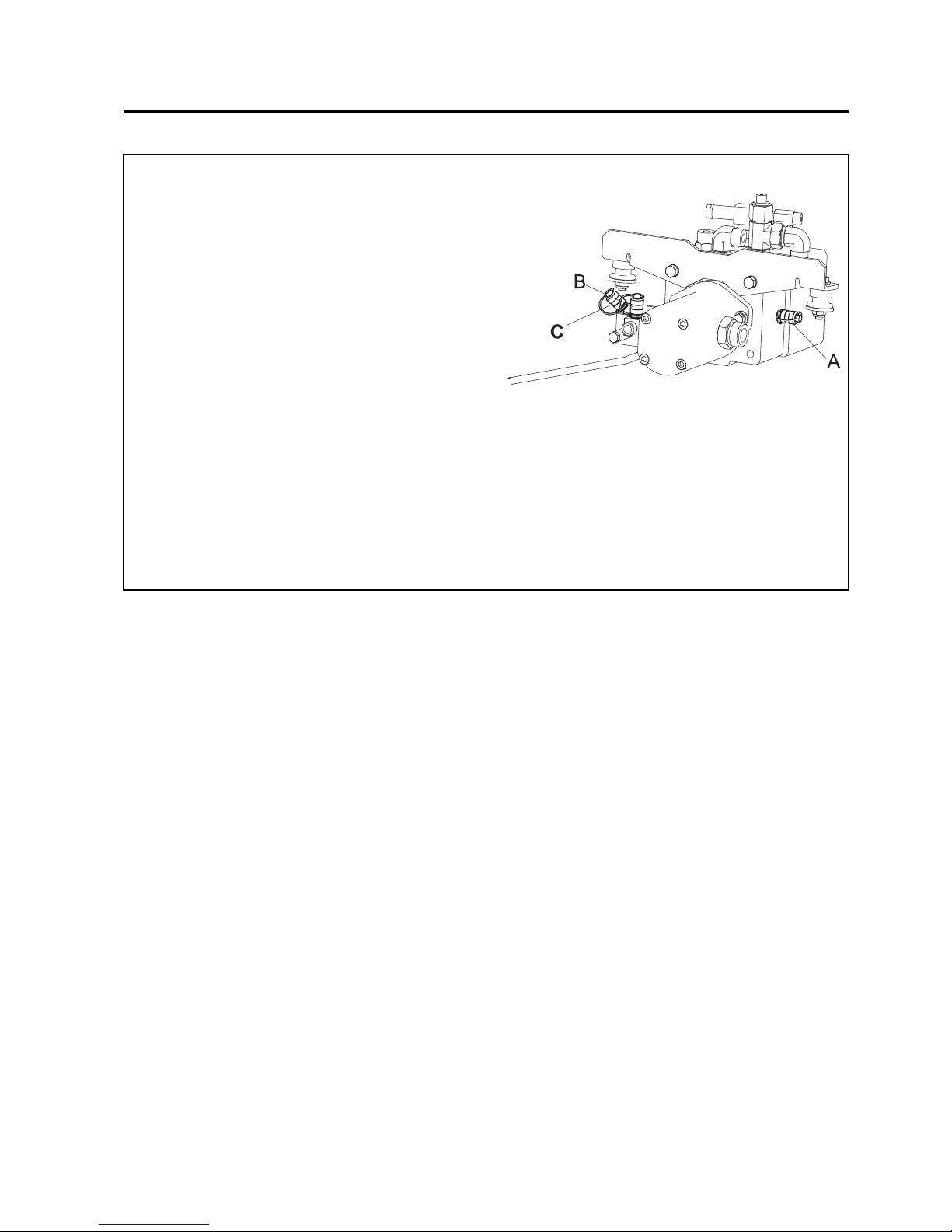
en-37
JACOBSEN AR3
SAFETY, OPERATORS & MAINTENANCE MANUAL
8.6 HYDRAULIC TEST PORTS
If any problems are experienced with the hydraulic
system service ports are provided to enable
pressures to be checked.
All tests, unless stated otherwise, should be carried
out with the hydraulic oil at normal working
temperature.
TEST PORTS
A. Transmission pressure: 210 bar (3045 psi).
B. Deck drive pressure: 210 bar (3045 psi).
C. Steering and lift pressure 110 bar (1595 psi).
NOTE: Any servicing of the hydraulic system must
be carried out by trained service personnel.
8 MAINTENANCE & LUBRICATION
Page 38
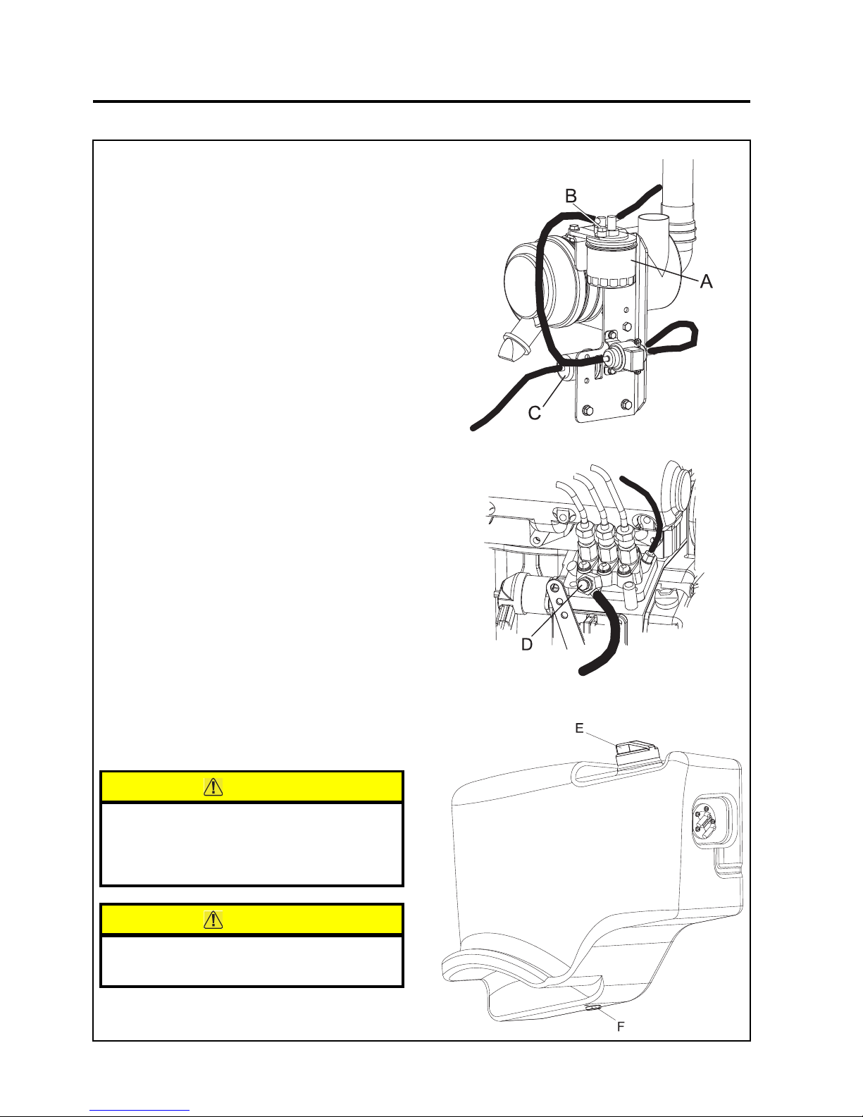
en-38
JACOBSEN AR3
SAFETY, OPERATORS & MAINTENANCE MANUAL
8.7 FUEL SYSTEM
Use Diesel fuel No.2-D (ASTM D975)
See engine manufacturer's manual for additional
information.
Bleeding air from fuel system
(a) Turn the ignition switch to the ON position
(don't start engine).
(b) Open air vent (B) on Fuel filter housing to
allow air to escape.
(c) Retighten air vent.
(d) Open air vent (D) on side of injection pump
to allow air to escape.
(e) Retighten air vent.
(f) Turn ignition to OFF.
Changing fuel filter
(a) Unscrew filter (A) from filter head.
(b) Remove filter and discard.
(c) Fit new filter to head.
(d) Bleed air from system as described above.
Replace In-line fuel (C)
Draining Fuel Tank
(a) Remov e filler cap (E).
(b) Remove drain plug (F).
(c) Drain diesel fuel in to a suitable container.
(d) Replace drain plug (F) and filler cap (E).
NOTE: If refilling fuel tank, bleed the system as
described above.
CAUTION
Contact with diesel fuel can damage your
skin. Use gloves when working with diesel
fuel. If you come in contact with diesel fuel,
wash it off immediately.
CAUTION
Dispose of used diesel fuel in accordance
with local regulations.
8 MAINTENANCE & LUBRICATION
Page 39
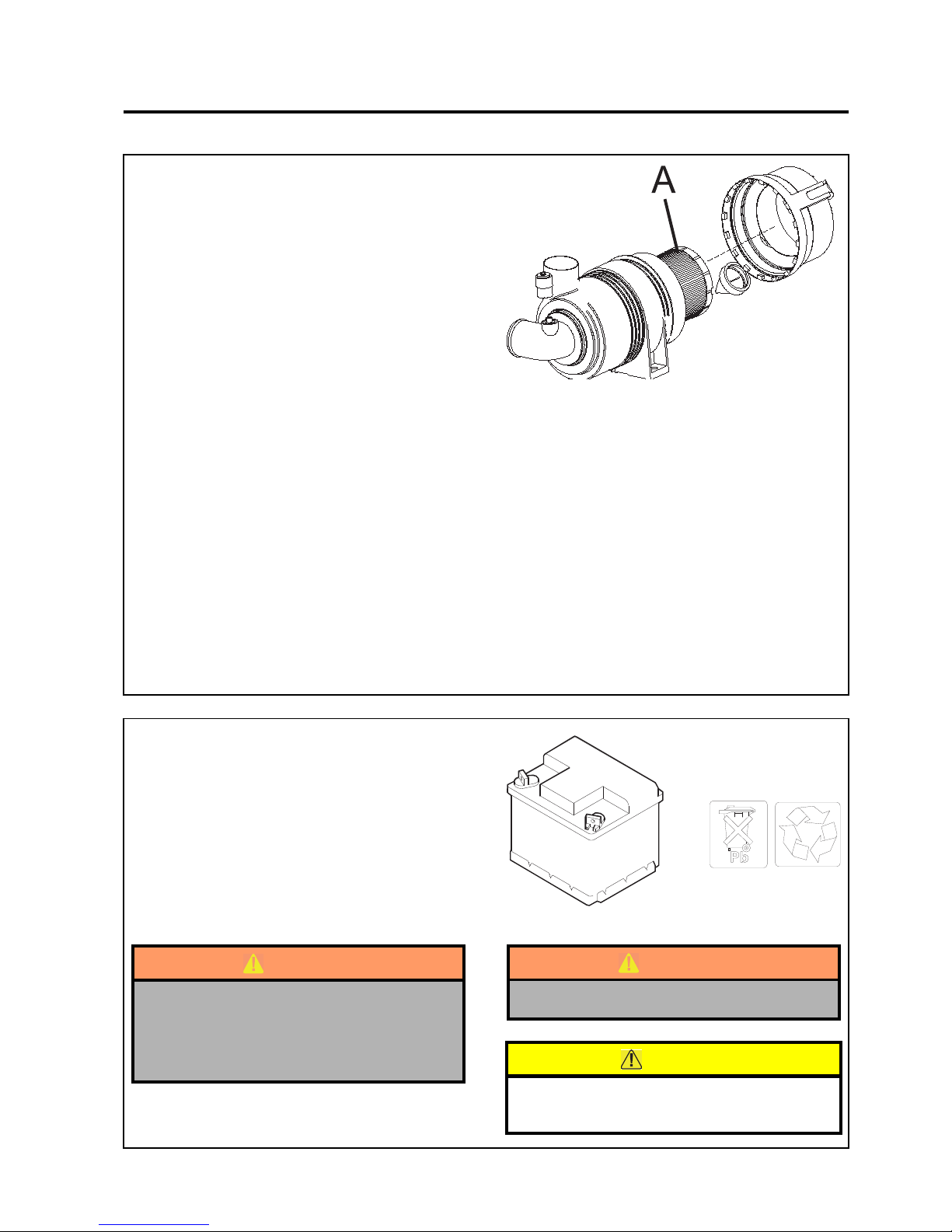
en-39
JACOBSEN AR3
SAFETY, OPERATORS & MAINTENANCE MANUAL
8.8 AIR CLEANER
Cleaning the air filter
NOTE: After 6 cleanings replace the filter element.
(a) Raise engine cover.
(b) Remove end cap of air filter cartridge.
(c) Remove loose dirt from element with
compressed air working from the clean to
dirty side, using compressed air max 6 bar
, with nozzle 5cm from element.
(d) reinstall filter element (press firmly against
rear shoulder)
(e) Replace end cap and fasten with clips
Change air filter
(a) Raise engine cover.
(b) Remove end cap of air filter cartridge.
(c) Remove accumulated dust or dirt.
(d) Remove filter element (A) (pull straight out
firmly)
(e) install new filter element (press firmly
against rear shoulder)
(f) Replace end cap and fasten with clips
NOTE: Extensive damage to engine can result
from an inadequate air supply.
8.9 BATTERY
(a) Keep fluid levels above battery plates.
(b) Keep battery post corrosion free
WARNING
Battery posts, terminals and related
accessories contain lead and lead
compounds.
WASH HANDS AFTER HANDLING
8 MAINTENANCE & LUBRICATION
WARNING
Wear eye protection when servicing battery.
CAUTION
Dispose of used batteries in accordance with
local regulations.
Page 40
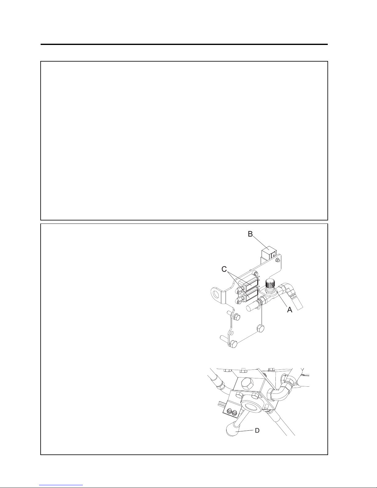
en-40
JACOBSEN AR3
SAFETY, OPERATORS & MAINTENANCE MANUAL
Storage
• Store petrol or diesel fuel in an approved
container in a cool dry place.
• Keep the machine and fuel containers in a
locked storage place to prevent tampering
and to keep children from playing with
them.
• Do not store fuel or petrol/diesel fuel
powered equipment in any closed area
where heating appliances, pilot lights or any
sort of open flame is present.
• Before storing, allow the engine to cool, and
drain fuel completely from fuel tanks and
containers.
• Maximum safety and best mowing results
can only be expected if the mower is
maintained and operated properly.
8.10 MACHINE MAINTENANCE
Other Regular Service.
• Verify proper operation of safety interlock
switches (Neutra l switch, S eat switch, et c.)
• Ensure nuts and bolts remain tight.
• visually inspect for hydraulic leaks.
• Keep engine bay clear of debris.
• Keep tyre pressure at correct level. See
section 4
• Follow the engine manufacturer’s
maintenance recommendations.
• If a label becomes worn or removed, see
the LABELS section of this manual or the
tractor Parts Manual for replacement
information.
NOTE: When washing machine with pressure spray
washers or steam cleaners, avoid washing bearing
areas because cleaning solutions might penetrate
bearing seals and cause premature bearing failure.
8 MAINTENANCE & LUBRICATION
8.11 FREEWHEEL CONTROL
The free wheel control is provided to allow the
machine to be moved when the engine is stationary.
Before the m achine can be m oved the Parkin g Brake
must be released. The brake release valve is situated
under the Operators Platform close to the front axle.
Move the Parking brake release lever D to the right
when viewed from the front of the machine. Rotate
the steering wheel clockwise to release the parking
brake.
The freewheel control is situated in the engine
compartment between the engine and the seat. To
gain access lift the engine cover. Rotate the control
knob A fully anticlockwise to obtain the transmission
free wheel function.
Rotate the freewheel control knob A fully clockwise
to return the transmission system to normal
operation.
DO NOT Do not tow the machine for more than a few
meters, or
allow the machine to free wheel down slopes even
when unloading down ramps.
Page 41
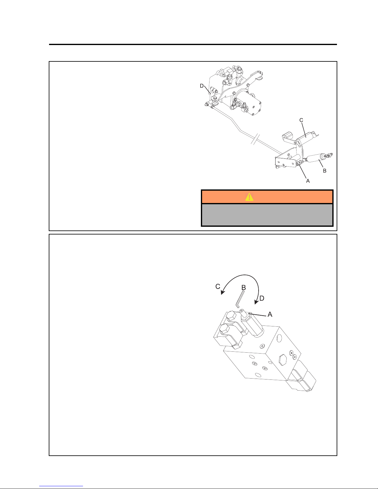
en-41
JACOBSEN AR3
SAFETY, OPERATORS & MAINTENANCE MANUAL
9.1 TRACTION CONTROL PEDAL
Adjustment to eliminate wheel creep.
1. Lift and support both front and rear wheels.
2. Remove ball joint A from foot pedal C to
allow damper B to set pedal neutral
position.
3. Start engine, manually move the pump
control lever D until wheels stop rotating.
4. Adjust ball joint A until holes in foot pedal
and ball joint align.
5. Reattach ball joint to foot pedal.
6. Move the foot pedal in forward & reverse
directions to ensure there is no creep in
neutral position.
9.2 WEIGHT TRANSFER ADJUSTMENT
The weight transfer bias can be adjusted on the lift
valve. The valve is accessible from the front of the
machine and is situated under the right hand side of
the footplate when facing the machine (left hand side
when viewed from the operating position).
To adjust:
1. Loosen the locknut A whilst holding the
threaded shaft still with the Allen Key B.
2. Using an Allen key B rotate the threaded
shaft clockwise in direction D to increase
weight onto the drive wheels when the
traction control switch is operated on the
control panel. This improves slope climbing
performance. To reduce weight on the
drive wheels when the traction control
switch is operated on the control panel,
rotate the threaded shaft counter clockwise
in direction C. This increases the ground
weight of the cutting unit and will reduce the
possibility of cutting unit “bounce” when
working at high speed on undulating
ground. It is recommended that the Allen
key is turned a 1/4 turn at a time and the
weight transfer tested.
3. Tighten locknut A. whilst holding the
threaded shaft still with the Allen Key B.
9 ADJUSTMENTS
WARNING
Properly support raised machinery with
jack stands.
Page 42
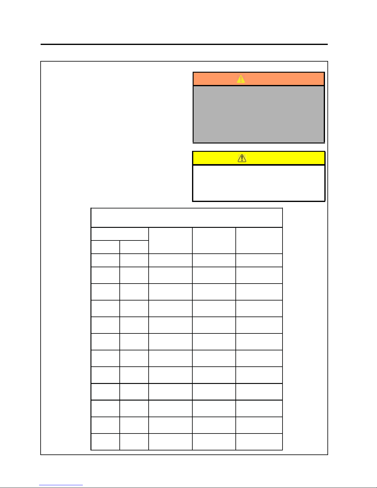
en-42
JACOBSEN AR3
SAFETY, OPERATORS & MAINTENANCE MANUAL
9 ADJUSTMENTS
9.3 HEIGHT OF CU T
Cutting height for decks can be adjusted from 3/4 to
4 in. (19-101.6 mm) in 1/2 in. (13 mm) increments.
Actual cutting height may vary somewhat from the
heights given depending on turf conditions and other
factors.
Note: When cutting undulating areas, lower cutting
heights may cause scalping. Adjust height
accordingly to prevent turf damage.
To Change the Height of Cut
1. Park the tractor on a flat, level surface. Fully lower
cutting units. Placed blocks under deck housing
so they are supported on all sides.
2. Refer to the chart provided for desired cutting
height.
Range of Cut
Height of Cut
13mm (1/2")
Spacers Below
Deck Housing
13mm (1/2")
Spacers Above
Deck Housing
6mm (1/4")
Spacer Location
mm inch
19 3/4 0 9 Above Housing
25 1 0 9 Below Housing
32 1-1/4 1 8 Above Housing
38 1-1/2 1 8 Below Housing
44 1-3/4 2 7 Above Housing
50 2 2 7 Below Housing
57 2-1/4 3 6 Above Housing
64 2-1/2 3 6 Below Housing
70 2-3/4 4 5 Above Housing
76 3 4 5 Below Housing
83 3-1/4 5 4 Above Housing
90 3-1/2 5 4 Below Housing
WARNING
To prevent serious injury, lower deck until
it is resting completely on the supports.
This will prevent it from accidentally
lowering while making adjustments.
Disengage all drives, engage parking
brake, stop engine and remove ignition
key.
CAUTION
Use proper lifting techniques when lifting or
lowering deck housing. The deck housing
assemblies weight approximately 25kg
(55Lbs)
Page 43
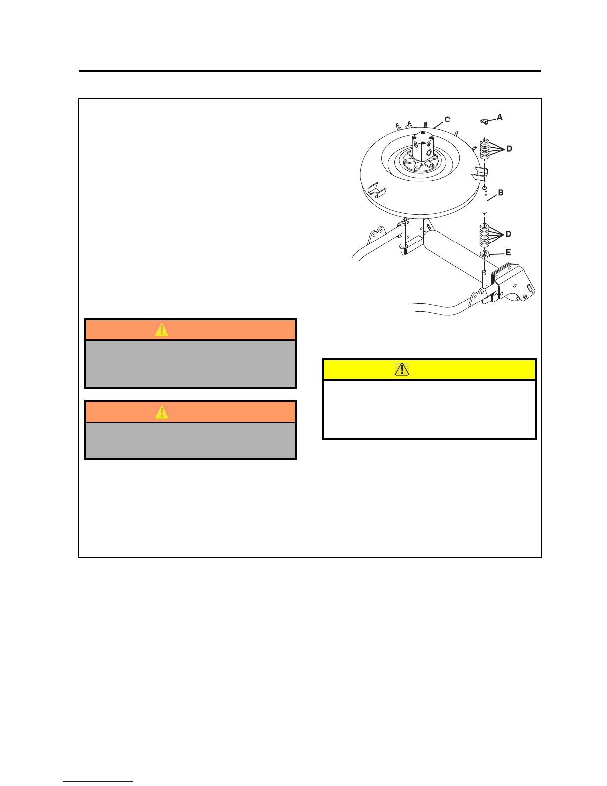
en-43
JACOBSEN AR3
SAFETY, OPERATORS & MAINTENANCE MANUAL
3. To lower height of cut, remove all three snap
lock pins (A). Lift outer spindle shaft (B) slightly
and remove 13mm (1/2") spacers (D) and / or 6mm
(1/4") spacer (E) from bottom one at a time until
desired height is obtained. Carefully remove
blocks and lower deck housing (C). Place
remaining spacers on top of spindle and insert
snap lock pins.
4. To raise height of cut, remove all three snap lock
pins (A). Carefully lift deck housing (C) above
desired cutting height and support with blocks.
Add 13mm (1/2" ) spacers (D) and / or 6mm (1/4")
spacer (E) as required until desired height of cut
is obtained. Lower deck housing. Place
remaining spacers on top of spindle and insert
snap lock pins. Washer is always on top, under
snap lock pin.
WARNING
Never use the machine without the decks
being fitted with either the rear discharge
chute or the blanking plate.
WARNING
The decks should only be mounted with the
discharge aperture to the rear.
9 ADJUSTMENTS
CAUTION
For best quality of cut, always place same
number of spacers under each housing on all
three spindles. Adjust all decks to the same
cutting height.
Page 44
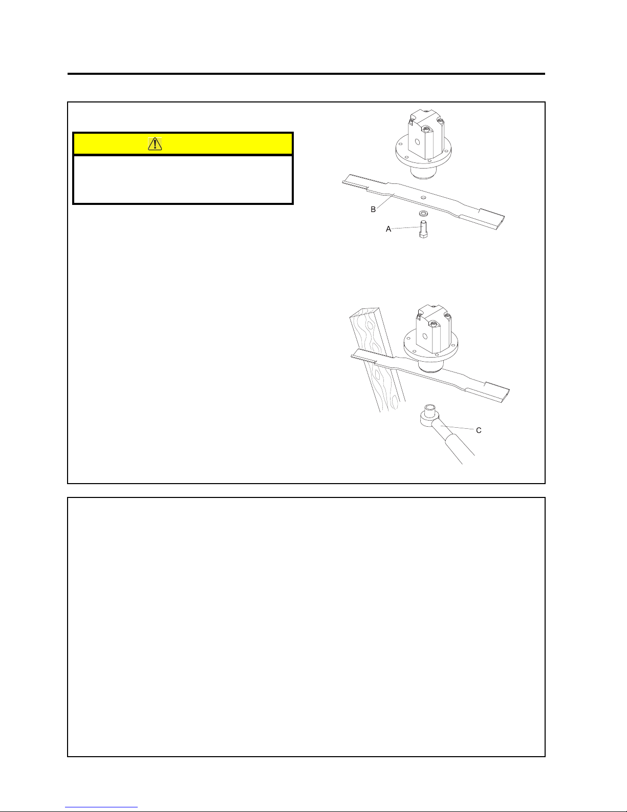
en-44
JACOBSEN AR3
SAFETY, OPERATORS & MAINTENANCE MANUAL
9 ADJUSTMENTS
9.5 BLADE SHARPENING
Blades may be sharpened by filing or grinding. When
sharpening, maintain blade balance within 19.4 g/cm
(5/8 oz/in). Failure to keep the blade balanced causes
excess vibration, blade wear and shortened blade
life, and may harm other mechanical components of
the machin e as well.
To check blade balance
1. Determine if there is a lighter end.
2. Attach a 3.9g (1/8 oz) weight to the lighter
end 127mm (5in) from the centre of the
blade.
3. If the blade is adequately balanced, the
weight should convert the light end into the
heaviest end. If correction is required, file
or grind the heavy end to obtain balance.
9.4 BLADE CHANGE
1. Remove blade bolt (A).
2. Remove blade (B) from deck .
3. Fit new blade.
3. Replace blade assembly to hydraulic motor
spindle.
4. Tighten blade bolt with torque wrench (C)
set to 95N-m (70 ft-lb) torque.
CAUTION
Blades are extremely sharp and can cause
severe cuts. For your protection, hold blade
with thick leather work glove only.
NOTES:
• Do not overheat or weaken blades when
sharpening.
• Do not straighten bent blades.
* If the lift portion of the blade is worn thin,
replace with a new blade.
• Replace cracked or bent blades.
• For greatest safety always use genuine
replacement blades .
Page 45
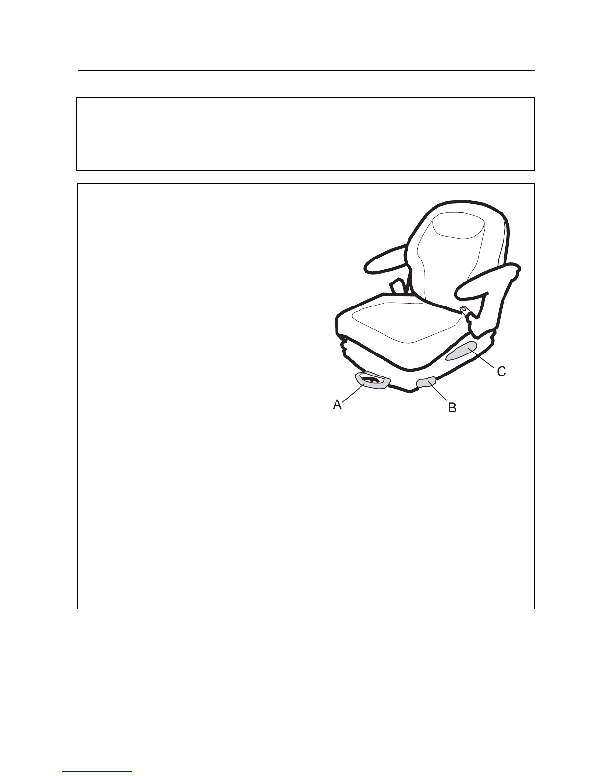
en-45
JACOBSEN AR3
SAFETY, OPERATORS & MAINTENANCE MANUAL
9 ADJUSTMENTS
9.7 SEAT (Milsco CE-200)
The seat can be adjusted for operator's weight and
leg reach to provide a comfortable position for
operating the machine.
A. ADJUSTMENT FOR OPERATOR WEIGHT
To Adjust:
Whilst sitting on the seat push knob A downwards
and allow it to slid back upwards until a comfortable
amount of suspension is found.
B. FORE AND AFT ADJUSTMENT
To Adjust:
The position of the adjusting lever is on the left hand
side of the seat below the seat cushion (B). By moving
the lever upwards, the seat can be slid backwards
and forwards. When in the desired position release
the lever to locate in one of the pre set positions.
C. BACK REST ADJUSTMENT
The back rest has three preset positions
To Adjust:
Move the lever upwards and slid the seat cushion
backwards and forwards to obtain a comfortable back
rest position.
NOTE: The seat is fitted with a microswitch to sense
operator presence. When the machine is fitted with
a ROPS frame or cab a lap belt is fitted and should
be worn at all times
9.6 SPEED LIMITER
The transport and mow speeds are factory set and
should not need altering.
NOTE: Textron Turf Care cannot be held responsible
for loss of performance or machine damage if these
speeds are adjusted outside the speeds shown in the
machine specification.
ADJUSTMENTS
Page 46
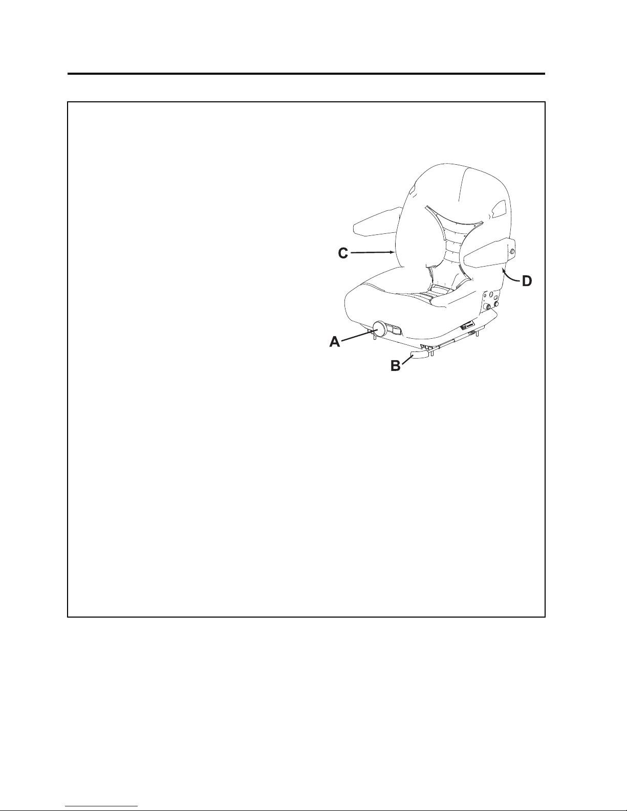
en-46
JACOBSEN AR3
SAFETY, OPERATORS & MAINTENANCE MANUAL
9.8 SEAT (Michigan V5300)
The seat can be adjusted for operator's weight and
leg reach to provide a comfortable position for
operating the machine.
A. ADJUSTMENT FOR OPERATOR WEIGHT
To Adjust:
Whilst standing in front of the machine, rotate knob
(A) clockwise or anticlockwise to move the red
indicator to the approximate operator weight.
B. FORE AND AFT ADJUSTMENT
To Adjust:
The position of the adjusting lever is on the left hand
side of the seat below the seat cushion (B). By moving
the lever upwards, the seat can be slid backwards
and forwards. When in the desired position release
the lever to locate in one of the pre set positions.
C. BACK REST ADJUSTMENT
To Adjust:
Rotate the adjuster (C) clockwise or anticlockwise
until a comfortable position is achieved.
D. ARM REST ADJUSTMENT
To Adjust:
Raise the arm rest to the vertical position and rotate
the adjustable stop to achieve a comfortable position.
NOTE: The seat is fitted with a microswitch to sense
operator presence.
When the machine is fitted with a OPS frame or cab
a lap belt is fitted and should be worn at all times
9 ADJUSTMENTS
Page 47
en-47
JACOBSEN AR3
SAFETY, OPERATORS & MAINTENANCE MANUAL
9.9 GENERAL INSTRUCTIONS FOR
GRAMMER SEATS
• The operating instructions must be read in
full before use.
• The operating instructions must be kept in
the vehicle and always be at hand.
• The driver’s seat may only be fitted,
serviced and repaired by specialist
personnel,
• In accordance with national regulations and
the vehicle manufacturer’s fitting
instructions.
• The national fitting regulations can be
obtained from GRAMMER or from
agencies of the company, or from the
vehicle manufacturer.
• A correctly functioning and individually
adjusted driver’s seat is essential to your
health.
• Take adequate care of your seat and have
it serviced regularly to ensure that it
functions correctly.
• The functional checks are to be carried out
at least as regularly as vehicle services
(see maintenance plan for vehicle).
• These operating instructions should always
be kept with the driver’s seat. If the seat is
passed on to a third party, it must be
accompanied by the relevant operating
instructions.
Safety instructions
• If you need to connect cables to the vehicle
supply network, strictly obs erv e the
following instructions:
• Before you connect a seat switch, seat
heater or compressor, you must obtain the
relevant electrical data for the respective
vehicle with reference to voltage, protection
and the kind of connections from the
manufacturer, from GRAMMER or the
company’s agencies.
• For safety reasons, the installation and
connection to the vehicle supply network
must be carried out by authorized specialist
personnel only.
• The seat connections must be protected
independently of other vehicle
components.
Notes Concerning Seat Switch:
Minimum and maximum current carrying capacity for
purely resistive load.
In case of inductive or capacitive load, the
manufacturer must install a protective circuit
breaker for the consumers in the vehicle. If there are
any uncertainties, please ask the vehicle
manufacturer before making connections.
Driver’s seats that have been adjusted incorrectly
have a smaller moving area. To prevent damage to
the driver’s back and to the seat, the seat must be
adjusted for the driver’s weight before use and
before every change of driver.
To prevent injury, no objects should be placed
within the moving area of the driver’s seat.
Before commissioning of the driver’s seat, possible
packaging material has to be
removed from the seat cushion and the backrest
upholstery.
To eliminate any risk of accident, the settings must
be checked to ensure they are correctly engaged
before the vehicle is driven.
Adjustments must not be made while driving.
After removal of the backrest upholstery, the
backrest frame must be supported, for example held
in place, before the backrest adjuster is operated. If
you fail to do so, there is a danger that the backrest
frame may jerk forward and cause injury.
Any changes to the series standard of the seat
(for example fitting parts which are not original
GRAMMER parts) may impair the safety standard to
which it has been tested.
Functions my be impaired, threatening your safety
For this reason, any changes in design of the seat
must be approved by GRAMMER.
During the removal and installation of the driver’s
seat, the corresponding instr uc tio ns by
the specific vehicle manufacturer must be strictly
observed!
9 ADJUSTMENTS
Seat Switch - Current Carrying Capacity
12V DC 10mA (min.)
250V DC 5A (max.)
DC Compressor
Seat Heat /
Compressor
12V 10A 20A
24V 10A 15A
48V 10A 10A
Page 48

en-48
JACOBSEN AR3
SAFETY, OPERATORS & MAINTENANCE MANUAL
9 ADJUSTMENTS
Do not hold onto the covers for lifting the driver’s
seats. If you do so anyway, there is an increased
risk of injury due to loosening or breaking covers.
Before you remove the driver’s seat, disconnect all
plug-in connections between the seat and the vehicle
supply network. When you replace the plug-in
connectors, make sure they are tight (dust, water).
Seatbelts can be retrofitted to the driver’s seat.
Seatbelts may only be fitted on the approval of
the vehicle manufacturer, as they increase the load
in the seat mounting area.
Seatbelts must be fitted in accordance with specific
national regulations and guidelines, and must be
approved by GRAMMER.
Retrofitted seatbelts must be fastened before
driving.
The seat belt must be replaced after an accident.
Where seatbelts are fitted to the driver’s seat, the
seat and seat mounting must be checked
additionally by specialist personnel after an accident
has occurred.
Fasteners must be, che cked regularly for tight
seat. If the seat wobbles there may be
loose bolts or other faults.
If you notice that the seat does not function correctly
(for example a defective seat suspension; improper
curvature of the lumbar support or damaged bellows),
contact a specialist workshop immediately to
arrange for repairs to be carried out.
If you fail to do so, your health may be affected and
the risk of accident increased.
Before the vehicle is used, switches that might be in
the seat (for shutting down mechanical equipment
when the driver leaves his/her seat) must be checked
for proper function
If malfunctions are detected, the vehicle must not be
driven.
– INCREASED RISK OF ACCIDENT –
Loads must not be placed on seats with a built in
switch, except for the driver’s weight during normal
use, as the vehicle may otherwise start to move by
itself.
– INCREASED RISK OF ACCIDENT –
If you take off t he wei ght from t he sea t wh ile dr iving,
this will cause the vehicle to stop.
Do not indent the bellows while there is load on the
driver’s seat.
– RISK OF CRUSHING –
Make sure that the interior of drivers seat remain s
free of foreign particles or liquids.
The driver’s seat is not watertight and must be
protected against splashes of water!
Any conversion or refitting work on a GRAMMER
driver’s seat must be performed exclusively in
authorised workshops by trained or suitably
qualified personnel and in adherence with the
applicable operating, mai nten anc e and ins ta ll atio n
instructions and in compliance with all relevant
national regulations.
Improper installation and assembly bear the risk of
personal injury or property damage and the proper
function of the driver’s seat or mounted parts can no
longer be guaranteed.
Guarantee
GRAMMER can provide no guarantee for damage
resulting from incorrect assembly, use
or repair of the driver’s seats.
Further details on the guarantee granted by
GRAMMER are stated on the invoice or the
delivery note. Warranty claims against GRAMMER
beyond the guarantee obligations described there
are excluded.
Page 49
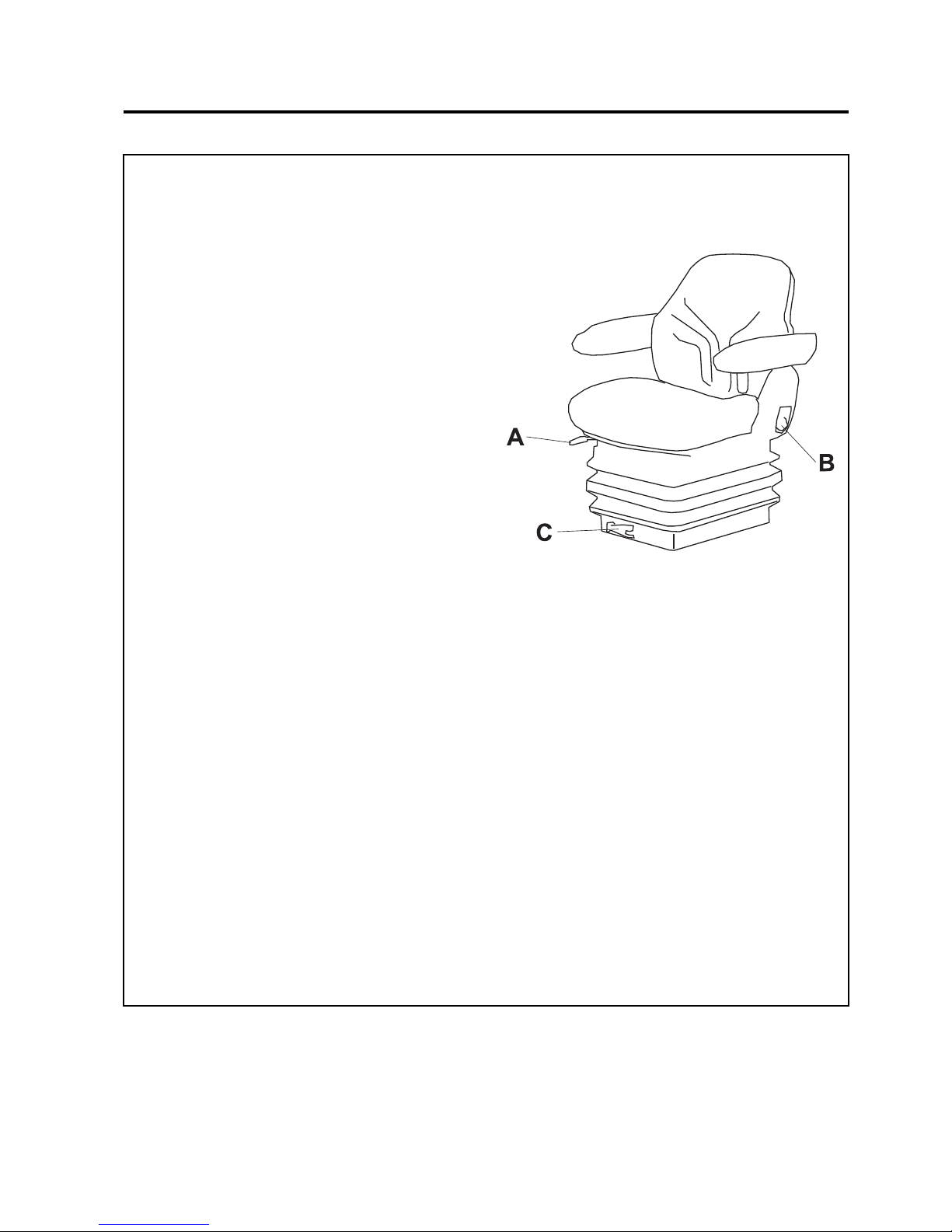
en-49
JACOBSEN AR3
SAFETY, OPERATORS & MAINTENANCE MANUAL
9.10 SEAT (Grammer MSG85)
The seat can be adjusted for leg reach, back rest
angle and operator weight to provide a comfortable
position for operating the machine.
A. FORE AND AFT ADJUSTMENT
To Adjust:
The position of the adjusting lever (B) is on the right
hand side of the seat below the seat cushion . By
pulling the lever up, the seat can be slid backwards
and forwards, when in the desired position release
the lever to locate in one of the pre set positions.
B. BACK REST ADJUSTMENT
To Adjust:
The position of the release lever (B) is on the left
hand side of the seat. While sitting on the seat pull
the release lever upwards to release the back rest.
(The back rest is spring loaded to fold onto the seat
cushion.) Lean back to obtain the desired position
for the back rest and release the lever to locate in
one of the pre set positions.
C. WEIGHT ADJUSTMENT
To Adjust:
The position of the operator weight adjust lever (C)
is on the front of the seat. To Change the operator
weight sitting pull the lever out and rotate the lever
while sitting on the seat.
D. HEIGHT ADJUSTMENT
To adjust:
When sitting on the seat the height can be adjusted
by holding the edge of the seat cushon, pushing your
weight down and lifting as the cushon as the
suspension returns t o its norm al posit ion. Th ere are
three pr-set positions, once the heighest has been
achived the seat returns to its lowest position.
NOTE:The seat is fitted with a microswitch to sense
operator presence.
When the machine is fitted with an OPS frame a lap
belt is fitted and should be worn at all times
9 ADJUSTMENTS
Page 50
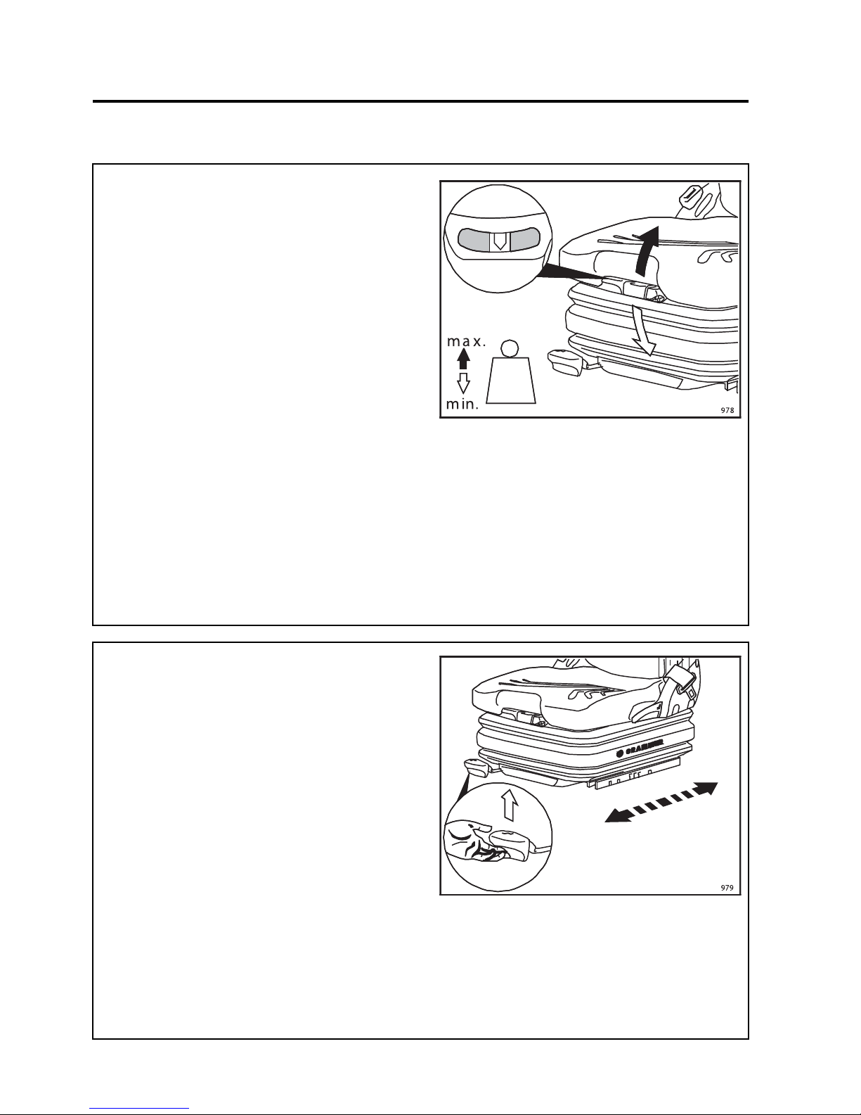
en-50
JACOBSEN AR3
SAFETY, OPERATORS & MAINTENANCE MANUAL
9.11.1 WEIGHT ADJUSTMENT
The seat is adjusted for the driver’s weight by pulling
or pressing the lever for seat weight adjustment and
with the driver sitting on the seat.
The driver’s weight is adjusted correctly when the
arrow is in the middle clear area of the viewing
window.
Within this viewing area, the individual height can be
adjusted to a minimum spring movement.
When the minimum/maximum weight adjustment has
been reached, you can hear it reaching the upper or
lower end stop.
To prevent damage to the health and material, the
setting for the driver’s weight must be checked and
adjusted individually before the vehicle is driven.
In order to avoid compressor damage during weight
adjustment, the compressor must be operated no
longer than 1 minute.
9.11.2 FORE/AFT ADJUSTMENT
The fore/aft adjustment is released by lifting the
locking lever.
WARNING! Risk of accident!
Do not operate the locking lever while driving.
WARNING! Risk of crushing!
Only touch the lever at the indented grip, do not
reach back under the lever.
After the adjustment, the locking lever must latch into
the desired position with an audible click. It should
not be possible to move the driver’s seat into another
position when it is locked.
Do not lift the locking lever with your leg or calf.
9.11 AIR SUSPENSION SEAT (Grammer MSG75 -521)
9 ADJUSTMENTS
Page 51
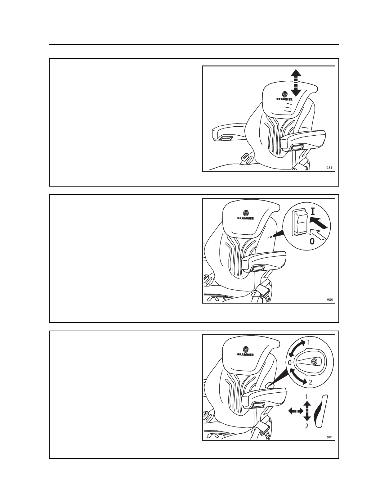
en-51
JACOBSEN AR3
SAFETY, OPERATORS & MAINTENANCE MANUAL
A
9.11.3 BACKREST EXTENSION * **
The backrest extension can be individually adjusted
by pulling it upwards or pushing it downwards over
the various locking increments up the end stop.
To remove the backrest extension, pull it upwards
over the end stop.
9.11.4 SEAT HEATER * **
The seat heater can be turned on/off by pressing the
switch.
1 = seat heater OFF
2 = seat heater ON
9.11.5LUMBAR SUPPORT
The lumbar support increases both the seating
comfort and the performance of the driver.
By turning the adjustment knob upwards, the
curvature in the upper part of the backrest cushion
can be adjusted. By turning the knob downwards, the
curvature in the lower part of the backrest cushion
can be adjusted.
0 = No curvature
1 = Max. curvature at the top
2 = Max. curvature at the bottom
* If Fitted
** Optional Extra
* If Fitted
** Optional Extra
9 ADJUSTMENTS
Page 52
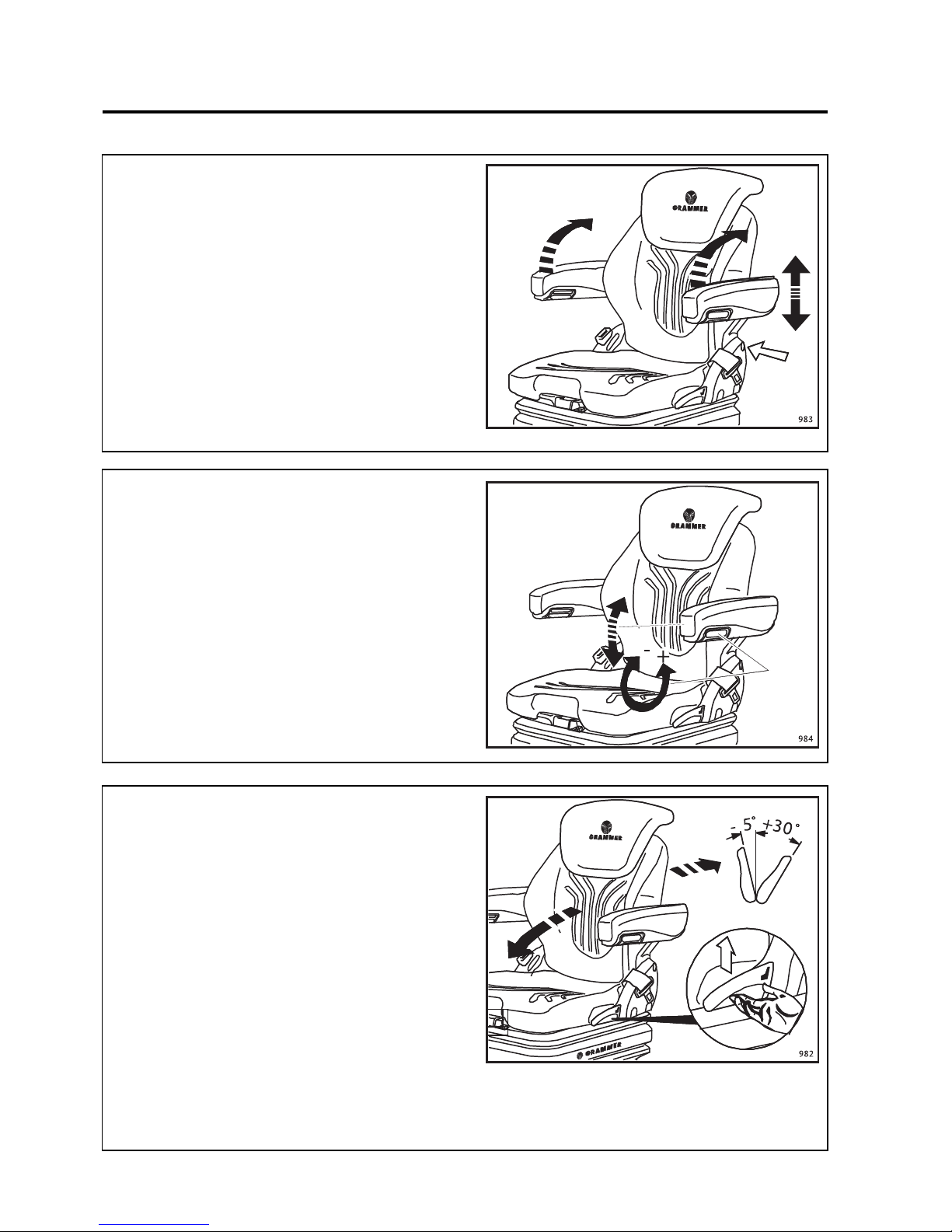
en-52
JACOBSEN AR3
SAFETY, OPERATORS & MAINTENANCE MANUAL
9 ADJUSTMENTS
9.11.6ARMRESTS * **
The armrests can be folded up if required and the
height individually adjusted.
To adjust the armrests for height, separate the round
cap (see arrow) from the cover, loosen the hexagon
nut (size 13 mm) behind it and adjust the armrests to
the desired position (5-steps) and tighten the nut
again.
Replace the cap onto the nut.
9.11.7ARMRE S T ADJUSTMENT *
The inclination of the armrests can be modified by
turning the adjustment knob.
When turning the knob to the outside (+) the front part
of the armrest will be lifted, when turning the knob to
inside (-) it will be lowered.
9.11.8BACKREST ADJUSTMENT
Moving the locking lever upwards loosens the
notching of the backrest adjustment.
After the adjustment, the locking lever must latch into
the desired position. It should not be possible to move
the backrest into another position when it is locked.
For an ergonomic use the backrest can be adjusted
in a range of –5 to +30 degrees (15 steps of 2.5
degrees each).
* If Fitted
** Optional Extra
* If Fitted
** Optional Extra
Page 53
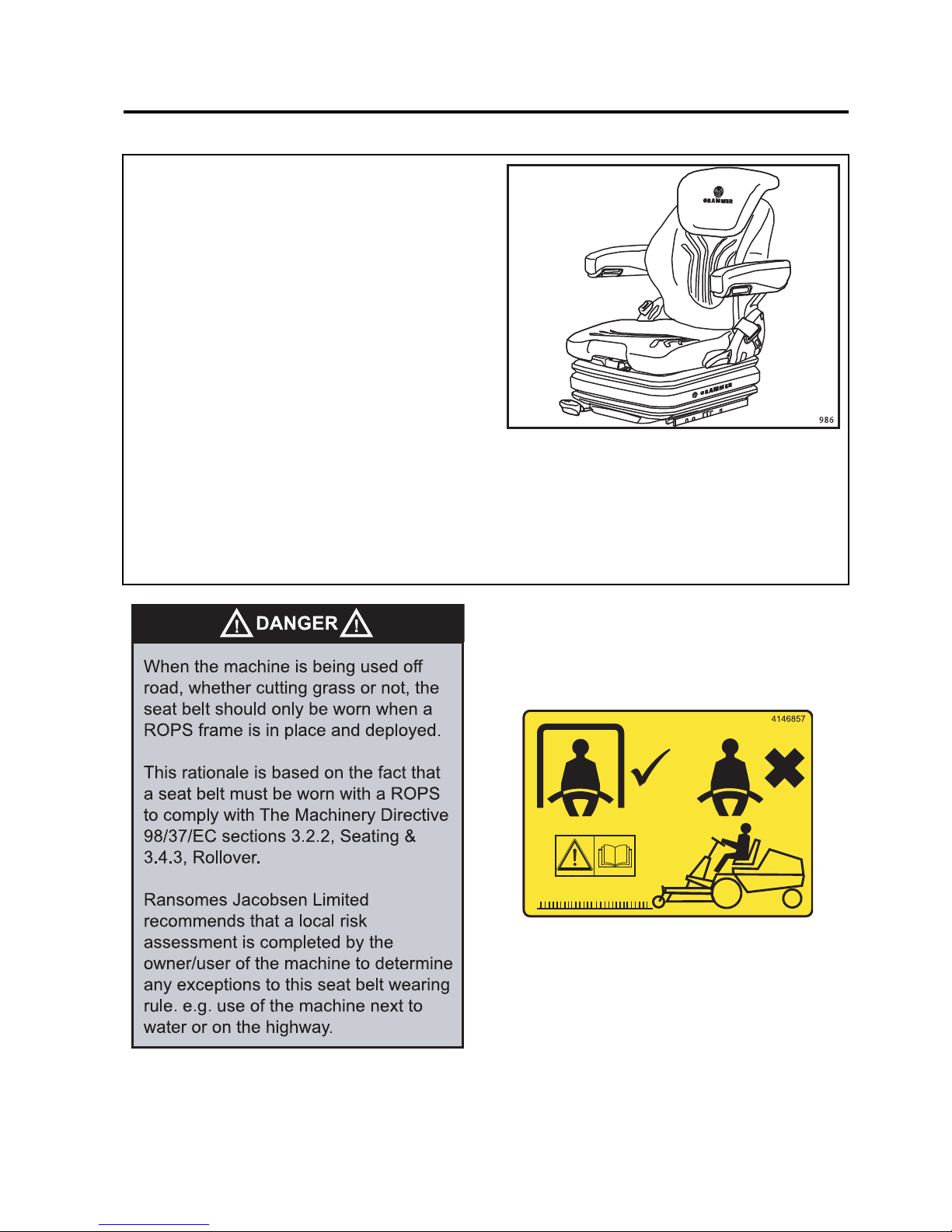
en-53
JACOBSEN AR3
SAFETY, OPERATORS & MAINTENANCE MANUAL
9.11.9MAINTENANCE
Dirt can impair the function of the seat,
so make sure you keep your seat clean!
Upholstery does not need to be removed from
the seat frame for cleaning.
Caution: Take care with the backrest - it may jerk
forward and cause injury!
When cleaning the backrest cushion the backrest
must be held in place when operating the
backrest l ever.
Attention: Do not clean the seat with a
pressure washer!
During cleaning the upholstery should not be
soaked through.
Use a standard commercially available
upholstery or plastic cleaning agent. Test first
for compatibility on a small, concealed
area.
9 ADJUSTMENTS
Page 54
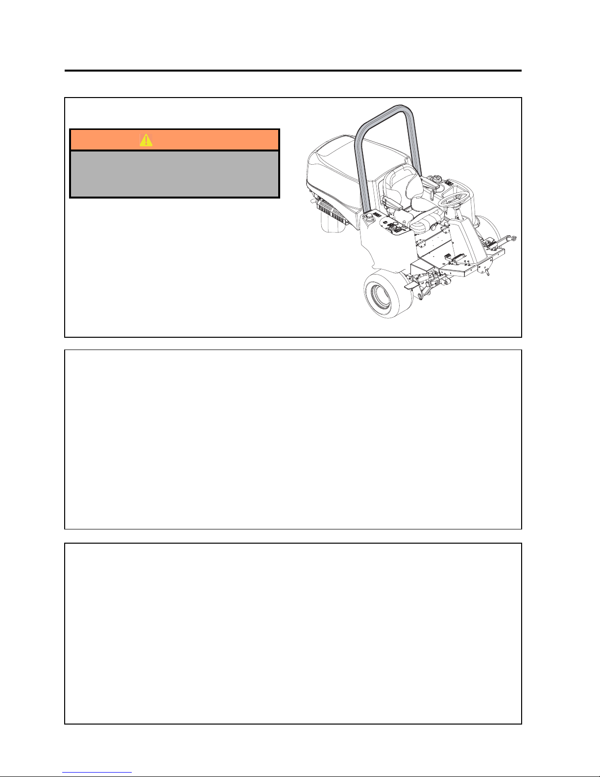
en-54
JACOBSEN AR3
SAFETY, OPERATORS & MAINTENANCE MANUAL
10 ACCESSORIES
10.1 OPS FRAME (LMAC164)
WARNING
When an OPS frame is fitted to a machine,
a seat belt must be fitted and worn by the
operator.
10.2 TRANSPORT LATCH KIT (LMAC174)
A transport latch kit is available for the front lift arms
10.3 WORKING LAMP KIT (LMAC163)
A Working lamp kit is available to fit two lamps to the
front of the operator plateform.
Page 55

en-55
JACOBSEN AR3
SAFETY, OPERATORS & MAINTENANCE MANUAL
11.1 GENERAL
The troubleshooting chart below lists basic problems that may occur during start-up and operation. For more
detailed information regarding the hydraulic and electrical systems contact your area Jacobsen Distributor.
11 TROUBLESHOOTING
Symptoms Possible Causes Action
Engi ne will not start.
1. Glow Plug has not time d out.
1. Reset ignition switch and allow glow plug to
time out b efore cranking engine.
2. Battery low on charge or
defective .
2. Inspect condition o f battery and battery
connections.
3. Fuel tank empty o r fuel
contaminated.
3. Fill tank with fresh fuel. Change filter, Bleed air
from lines .
4. Blown Fuse. 4. Replace Fuse.
5. Defective Starter Relay. 5. Test and replace relay if neccesary.
6. Brake switch is not on. 6. Ensure brake switch is on.
7. Mow switch set to cut. 7. Set mo w s witch to off.
8. Transport pedal not in neutral
8. Remove foot from pedal, cheek pedal returns
to the neutral po s ition.
Engine hard to start
or runs poorly.
1. Fuel tank empty or fuel
contaminated.
1. Fi ll ta nk wi th fres h fuel. C hange filter, Bleed a ir
from lines .
2. Air Cleaner blocked or dirty. 2. Check air cleaner, replace as neccesary.
3. Injectors, fuel pump. 3. Consult engine manual.
4. Other Engine Problem 4. Consult engine troub leshooting guide .
Engine Stops.
1. Fuel tank empty 1. Fill with fresh fuel and bleed li nes
2. Interlocks not s e t b e fo re le aving
operators seat
2. Ensure Parking Brake is on & Mow switch is
in the off position.
Engine Overheating.
1. Coolant level low
1. Inspect and add 50/50antifreeze solution if
required.
2. Radiator air intake restricted 2. Clean wire mesh guard at radiator.
3. Wa terpump/alternator belt or fan
belt loose or broken.
3. Inspect waterp ump/alternator belt and fan belt.
Ti ghten if neccesary.
Battery not holding
charge . Battery light
on.
1. Loose or corroded battery
terminals.
1. Inspect terminals, clean and tighten as
required.
2. Low electrolyte level in battery. 2. Refill battery with distelled water
3. Alternator belt loose or broken.
3. Inspectwaterp ump/alternator belt. Tighten if
neccesary.
4. Alternator defective. 4. See engine manual.
Decks cut unevenly.
Poor quality of cut.
1. Cutting blades are worn. 1. Replace blades.
2. Engine speed too low. 2. Check engine speed, run engine at full throttle.
3. Cutter m o to rs wo rn.
3. Check case drain leakage & flow check
cutti ng circuit.
4. Ground speed to high 4. Set work speed stop.
5. Ground weight incorrectly
adjus ted
5. Adj ust g r ound wei ght c ontrol va l ve unti l cor r ect
gr ound w ei ght is a chi eved.
Page 56
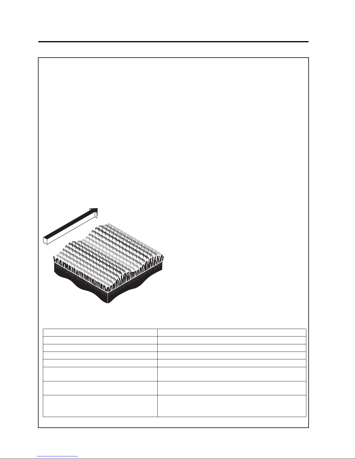
en-56
JACOBSEN AR3
SAFETY, OPERATORS & MAINTENANCE MANUAL
11 TROUBLESHOOTING
11.2 Quality of Cut Troubleshooting
It is recommended that a “test cut” be performed to evaluate the mower’s performance before beginning repairs.
An area should be available where “test cuts” can be made. This area should provide known and consistent turf
conditions to allow accurate evaluation of the mower’s performance.
Another “test cut” should be performed after the completion of the repairs and/or adjustments to verify the
mower’s performance.
Before performing a “test cut” to diagnose cut appearance and mower performance, the following items should
be verified to ensure an accurate “test cut.”
1. Mowing (Ground) Speed
2. Blade Sharpness
3. Height-of-Cut (HOC)
4. Roller and Roller Bearing Condition
5. Blade Speed
11.2.1Washboarding
Washboarding is a cyclical pattern of varying cutting
heights, resulting in a wave-like cut appearance. In
most cases, the wave tip-to-tip distance is
approximately 6—8 in. (15—20 cm). Color variation
(light-to-dark) may also be noticed.This condition is
usually caused by a rocking motion in the cutting
unit(s). This condition is found mostly on mowers
with multiple (suspended) cutting
units.Washboarding may also be caused by
variations in the turf.
NOTE: Arrow indicates direction of travel.
Probable Cause Remedy
Mowing (ground) speed is too fast. Reduce mowing (ground) speed.
Grass build-up on roller. Clean the roller and scraper.
Roller is out of round. Replace roller.
Mowing in the same direction. Change mowing direction regularly.
Cutting units have too much or too little weight
on them.
Use weight transfer switch to transfer weight on or off cutting
units. (Refer to Parts & Maintenance Manual.)
Insufficient engine speed, not set to specification.
Check/adjust engine speed. (Refer to Parts & Maintenance
Manual.)
Hydraulic system and/or rotary drive motor
performance is reduced.
Check hydraulic system performance (pump output, motor
operation, valve operation, relief valve settings, etc.).
Page 57

en-57
JACOBSEN AR3
SAFETY, OPERATORS & MAINTENANCE MANUAL
11 TROUBLESHOOTING
11.2.2Step Cutting
NOTE: Arrow indicates direction of travel.
Step cutting occurs when grass is cut taller on one
side of a cutting unit than the other or on one side of
mower to the other. This is usually caused by
mechanical wear or an incorrect roller or deck caster
adjustment.
Probable Cause Remedy
HOC (height-of-cut) settings are different from
one side of a cutting unit to the other or from one
cutting unit to another.
Check HOC adjustment of cutting units. (Refer to Parts &
Maintenance Manual.)
Worn roller bearings or deck caster wheels. Check/replace roller bearings and/or deck caster wheels.
Cutting unit movement is restricted. Check/remove cutting unit movement restriction.
Variations in turf density Change mowing direction.
Machine ride height is uneven side to side.
Check/adjust proper tire inflation pressure. (Refer to Parts
& Maintenance Manual.)
Cutting unit height is uneven side to side. Check/adjust for even mower weight distribution.
Page 58
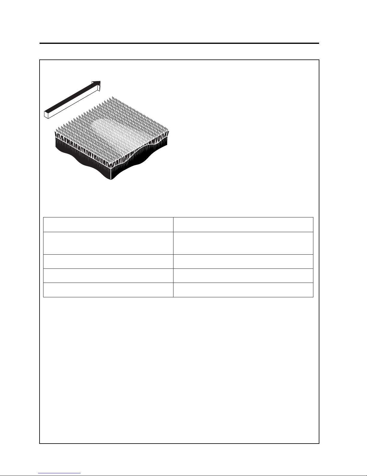
en-58
JACOBSEN AR3
SAFETY, OPERATORS & MAINTENANCE MANUAL
11 TROUBLESHOOTING
11.2.3Scalping
NOTE: Arrow indicates direction of travel.
Scalping is a condition in which areas of grass are
cut noticeably shorter than the surrounding areas,
resulting in a light green or even brown patch. This
is usually caused by an excessively low height-ofcut setting and/or uneven turf.
Probable Cause Remedy
HOC (height-of-cut) settings are lower than normal.
Check and adjust the HOC settings. (Refer to Parts &
Maintenance Manual.)
Turf too uneven for the mower to follow. Change mowing direction.
Cutting too much grass at one time. Mow more often.
Mowing (ground) speed is too fast. Reduce mowing (ground) speed.
Page 59
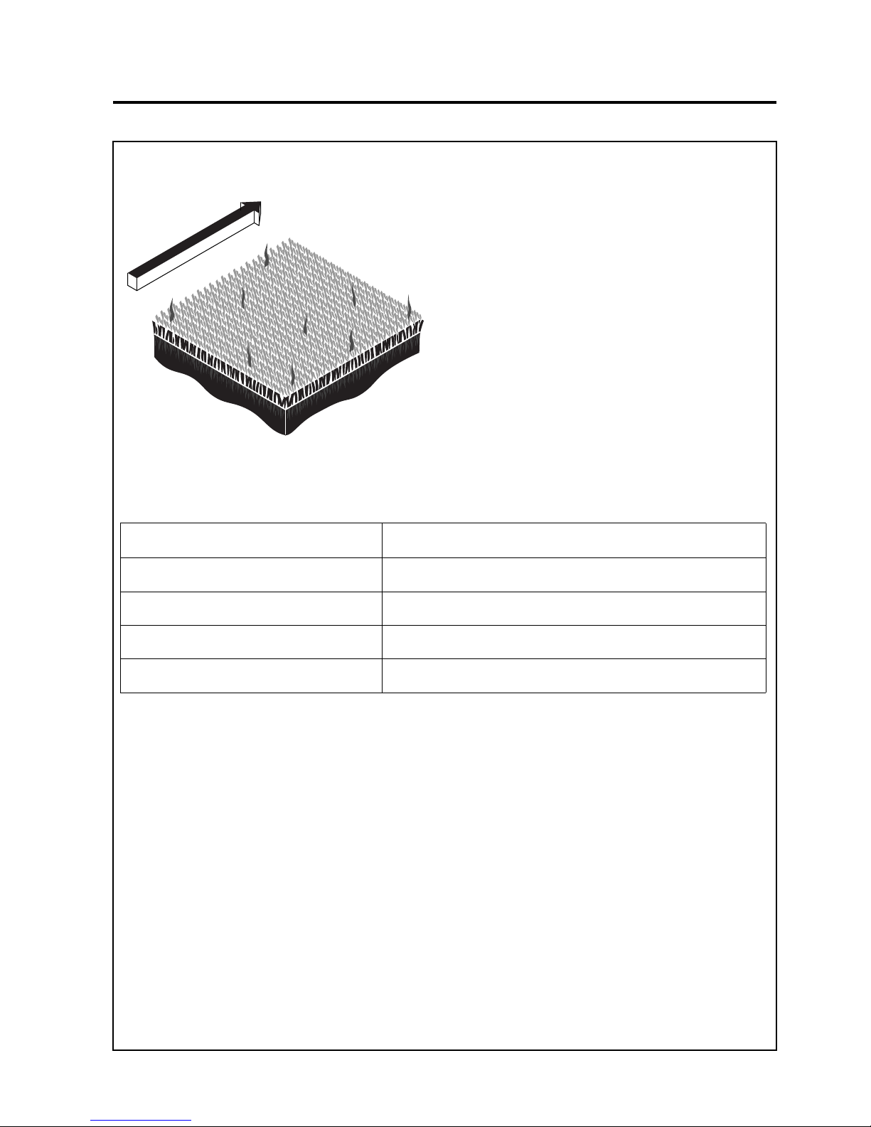
en-59
JACOBSEN AR3
SAFETY, OPERATORS & MAINTENANCE MANUAL
11 TROUBLESHOOTING
11.2.4Stragglers
NOTE: Arrow indicates direction of travel.
Stragglers are scattered blades of uncut or poorly
cut grass.
Probable Cause Remedy
Dull cutting blade(s). Sharpen blade(s). (Refer to Parts & Maintenance Manual.)
Mowing (ground) speed is too fast. Reduce mowing (ground) speed.
Grass is too tall. Mow more often.
Mowing in the same direction. Change mowing direction regularly.
Page 60
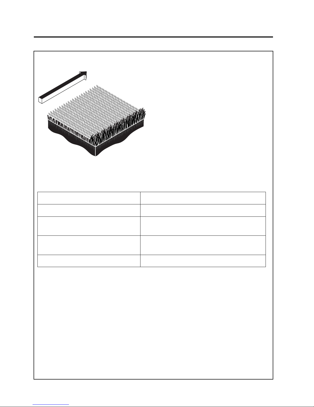
en-60
JACOBSEN AR3
SAFETY, OPERATORS & MAINTENANCE MANUAL
11 TROUBLESHOOTING
Probable Cause R emed y
Damaged blade(s). Replace blade(s).
Turning too aggressively. Cutting units don’t
overlap during turns or on side hills.
Turn less aggressively to allow cutting units to overlap.
Change mowing direction or pattern on side hills.
Tire mats down grass before it is cut.
Check/adjust tire inflation pressure. (Refer to Parts &
Maintenance Manual.)
Wet grass is matted down before it is cut. Cut when grass is dry.
11.2.5Streaks
NOTE: Arrow indicates direction of travel.
A streak is a line of uncut grass. This is usually caused
by a damaged blade.
Page 61
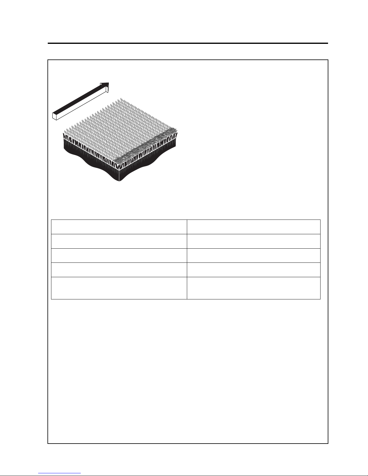
en-61
JACOBSEN AR3
SAFETY, OPERATORS & MAINTENANCE MANUAL
11 TROUBLESHOOTING
11.2.6Windrowing
NOTE: Arrow indicates direction of travel.
Windrowing is the deposit of clippings concentrated
at one end of cutting unit(s) or between cutting units,
forming line(s) in the direction of travel.
Probable Cause Remedy
Grass is too tall. Mow more often.
Mowing while grass is wet. Mow when grass is dry.
Grass built up on roller. Clean rollers and scrapers.
Grass collecting on mower or cutting unit frame. Clear cutting unit(s) discharge deflector.
Page 62
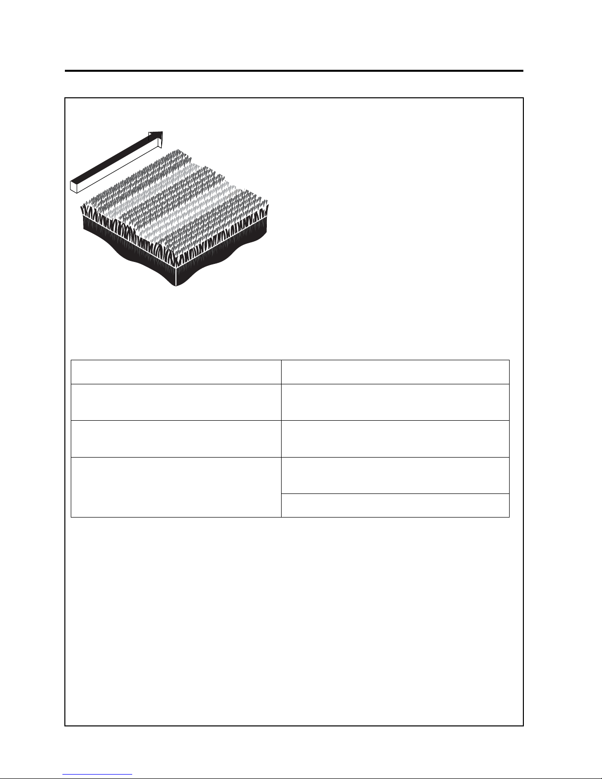
en-62
JACOBSEN AR3
SAFETY, OPERATORS & MAINTENANCE MANUAL
11 TROUBLESHOOTING
11.2.7Mismatched Cutting Units
NOTE: Arrow indicates direction of travel.
Mismatched cutting units is a pattern of varying
cutting heights, resulting in a stepped cut
appearance, usually due to mismatched HOC
(height-of-cut) adjustment from one cutting unit to
another.
Probable Cause Remedy
HOC inconsistent from one cutting unit to another.
Check/adjust HOC on cutting units to same height.
(Refer to Parts & Maintenance Manual.)
Difference in rotary cutting unit speeds.
Check operation of rotary cutting motor(s) and repair/
replace as necessary.
Difference in mower ride height side to side.
Check/adjust tire inflation pressure. (Refer to Parts &
Maintenance Manual.)
Check/adjust for even mower weight distribution.
Page 63

en-63
JACOBSEN AR3
SAFETY, OPERATORS & MAINTENANCE MANUAL
11 TROUBLESHOOTING
Page 64
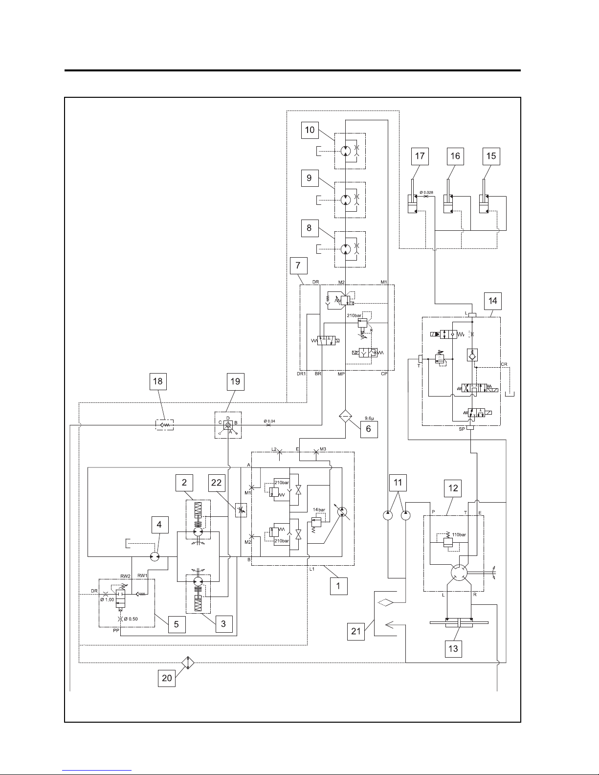
en-64
JACOBSEN AR3
SAFETY, OPERATORS & MAINTENANCE MANUAL
12.1 HYDRAULIC CIRCUIT
12 SCHEMATICS
Page 65

en-65
JACOBSEN AR3
SAFETY, OPERATORS & MAINTENANCE MANUAL
KEY TO HYDRAULIC DIAGRAM
1 Transmission Pump
2 Hydraulic Wheel Motor Front
3 Hydraulic Wheel Motor Front
4 Hydraulic Wheel Motor Rear
5 Hydraulic Flushing Valve
6 Hydraulic Filter
7 Hydraulic Cutter & Brake Valve
8 Hydraulic Deck Motor
9 Hydraulic Deck Motor
10 Hydraulic Deck Motor
11 Cutter & Steering Pump
12 Hydraulic Steering Unit
13 Hydraulic Steering Cylinder
14 Hydraulic Lift Valve
15 Hydraulic Lift Cylinder
16 Hydraulic Lift Cylinder
17 Hydraulic Lift Cylinder
18 Hydraulic Check Valve
19 Hydraulic Brake Valve
20 Hydraulic Oil Cooler
21 Hydraulic Tank
22 Freewheel Valve
12 SCHEMATICS
Page 66
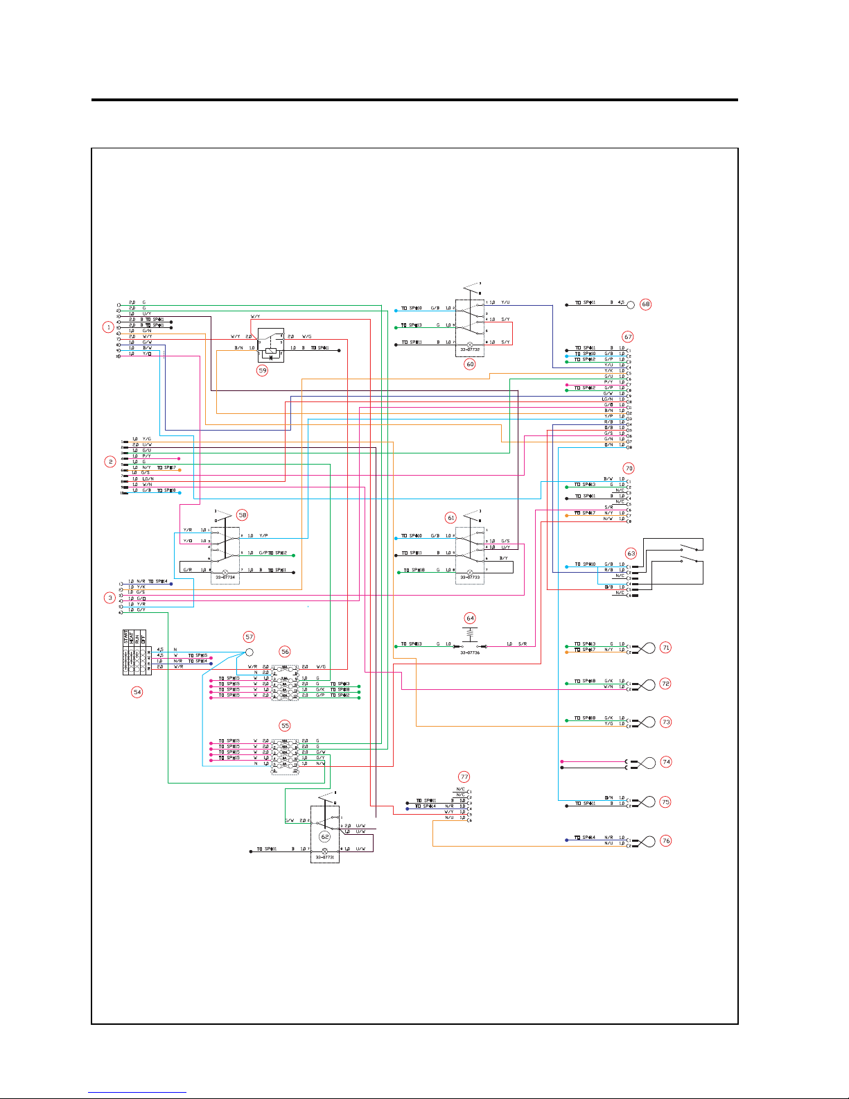
en-66
JACOBSEN AR3
SAFETY, OPERATORS & MAINTENANCE MANUAL
12.2 ELECTRICAL CIRCUIT INSTRUMENT
12 SCHEMATICS
TO SP#19
TO SP#19
2
TO SP#19BP/Y 1.0
1.0
1
TO SP#11
Page 67
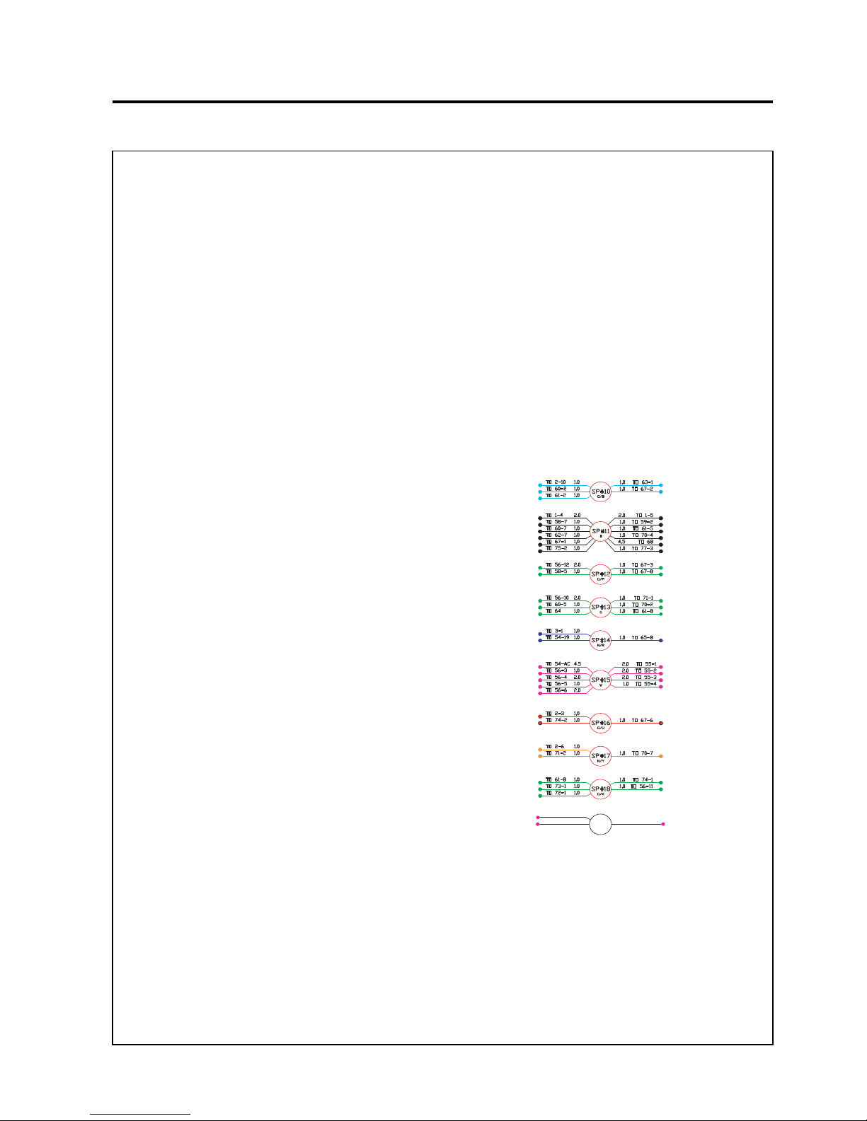
en-67
JACOBSEN AR3
SAFETY, OPERATORS & MAINTENANCE MANUAL
KEY TO WIRING DIAGRAM
1 Split to Main Harnes s
2 Split to Main Harnes s
3 Split to Main Harnes s
54 Key switch
55 Fuse Box 1
56 Fuse Box 2
57 Battery, Positive
58 Weight Transfer Switch
59 Start Relay
60 Mow Switch
61 Parking Brake Switch
62 Working Lamp Switch
63 Joystick
64 Setup Switch (Multi Function Gauge)
67 Module (Control)
68 Battery, Negative
70 Multi Function Gauge
71 Alternator Lamp
72 Engine Oil Pressure Lamp
73 Hydraulic Filter Warning Lamp
74 Engine Over Temperature Warning Lamp
75 Module Fault Warning Lamp
76 Glow Plug Timer Lamp
77 Glow Plug Timer
CABLE COLOUR CODE
RRed
G Green
O Orange
SGrey
BBlack
WWhite
KPink
P Violet
YYellow
UBlue
NBrown
LG Light Green
E.G. R/W = Red/White
67 Module Connections
10V
25V O/P
3 +12V IGP Input
4 5V Input from Mow Switch
5 12V Mow Solenoid O/P
6 Temperature Switch
7 12V Over Temperature Switch O/P
8 +12V IGP Input
9 12V Raise Solenoid O/P
10 12V Fuel Solenoid O/P
11 12V Backlap Solenoid O/P
12 12V Start Relay O/P
13 12V Lower Solenoid O/P
14 5V Raise Signal I/P
15 5V Lower Signal I/P
16 5V Park Brake Signal I/P
17 5V Seat Switch Signal I/P
18 12V Warning Lamp O/P
70 Multi Function Gauge Connections
1 Fuel Sender
2IGP
3Not Used
4 Ground
5Not Used
6 Set Up Enable
7 Alternator Lamp
8 Battery +ve Fuse
63 Joystick Connections
1 SV Input
2 Raise Switch
5Lower Switch
TO 74-1TO 74-1
TO 2-4TO 2-4
TO 67-7TO 67-7
SP#19SP#19
1.01.0
1.01.0
P/YP/Y
1.01.0
Console Splices
12 SCHEMATICS
Page 68
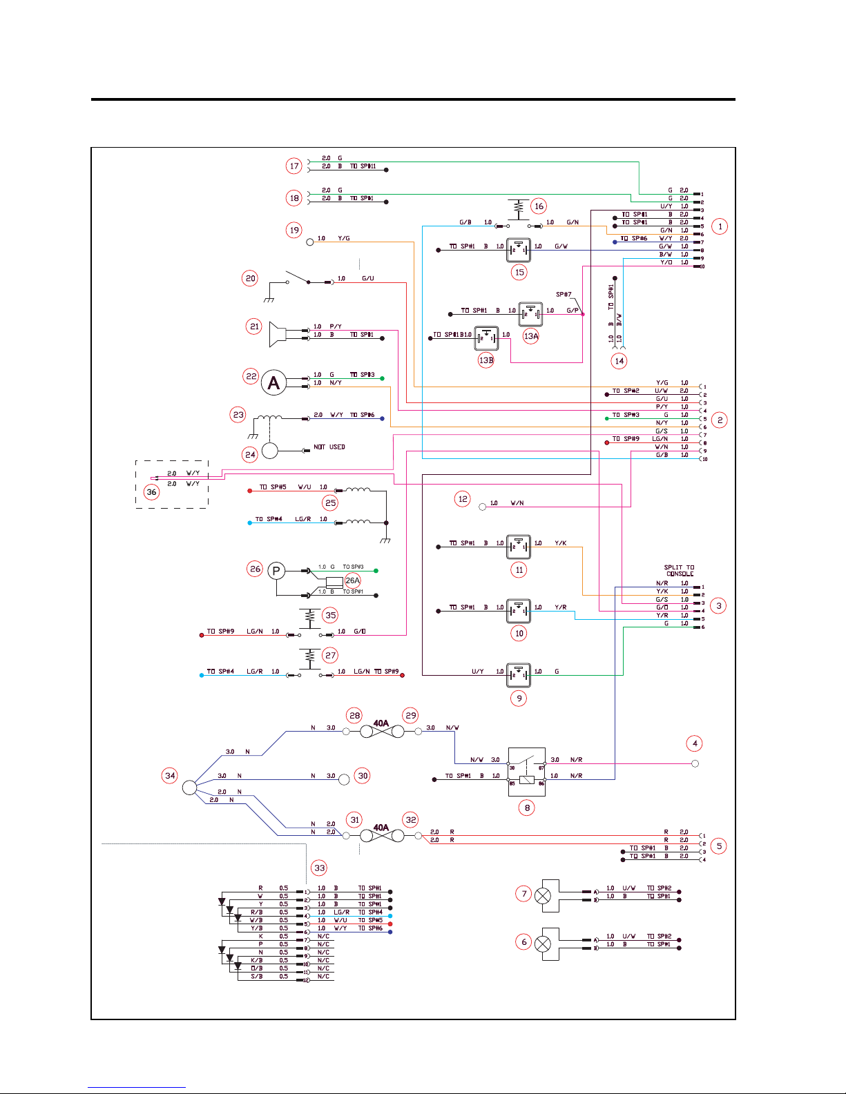
en-68
JACOBSEN AR3
SAFETY, OPERATORS & MAINTENANCE MANUAL
12.3 ELECTRICAL CIRCUIT MAIN
12 SCHEMATICS
Page 69
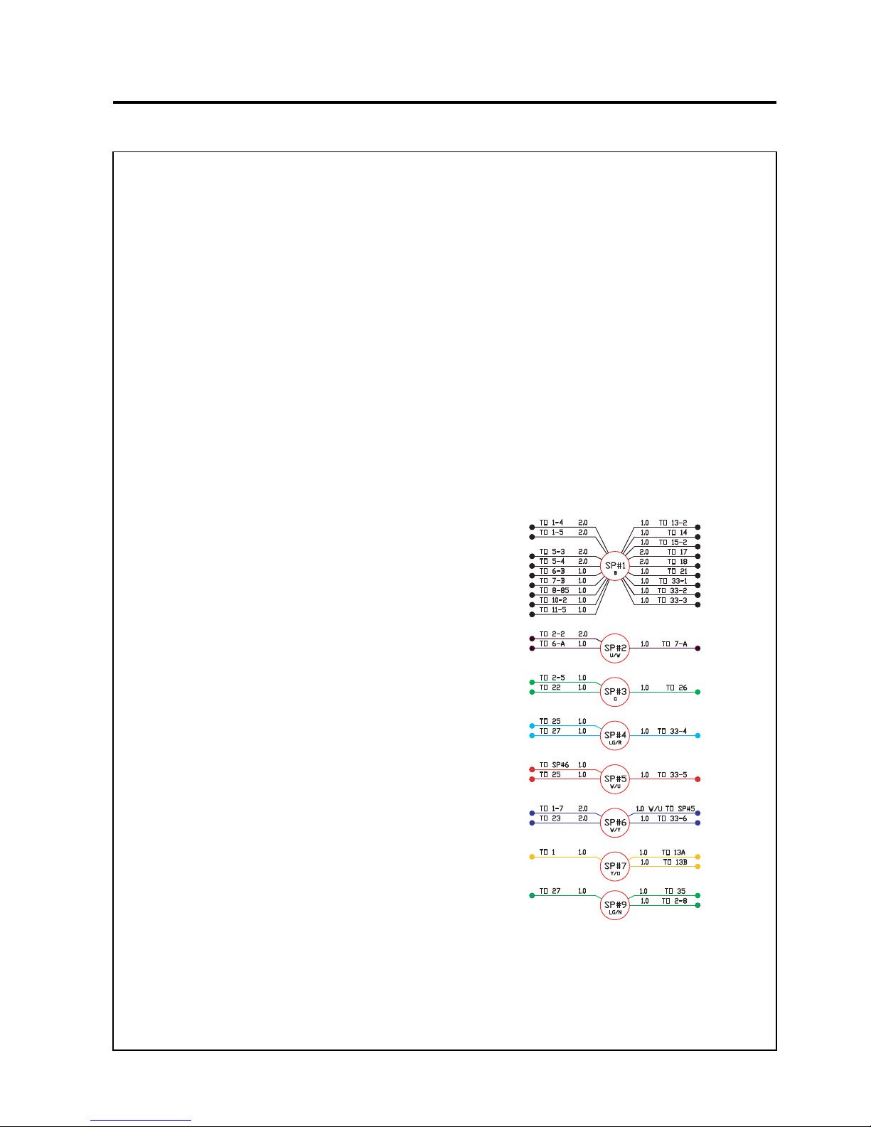
en-69
JACOBSEN AR3
SAFETY, OPERATORS & MAINTENANCE MANUAL
KEY TO WIRING DIAGRAM
1 Split to Console
2 Split to Console
3 Split to Console
4 Glow Pl ugs
5 Split to Cab
6 Working Lamp
7 Working lamp
8 Glow Pl ug Rela y
9 Brake Solenoid
10 Lower Solenoid
11 Cutter Solenoid
12 Engine Oil Pressure Switch
13a Weight Transfer Solenoid
13b Weight Transfer Solenoid
14 Fuel Level Sender
15 Raise Solenoid
16 Seat Switch
17 Accessory Socket 1
18 Accessory Socket 2
19 Hydraulic Oil Filter Switch
20 Engine Temperature Switch
21 Horn
22 Alternator Rotor
23 Starter Solenoid
24 Back Start Connector (not used)
25 Fuel Solenoid
26 Fuel Pump
27 Brake Safety Switch
28 Glow Plug Fuse Connector
29 Glow Plug Fuse Connector
30 Alternator O/P
31 Cab Fuse Connector
32 Cab Fuse Connector
33 Diode Module
34 Starter Main Terminal
35 Backlap Selector Switch
36 Neutral Switch Bypass
CABLE COLOUR CODE
RRed
G Green
O Orange
SGrey
BBlack
WWhite
KPink
P Violet
YYellow
UBlue
NBrown
LG Light Green
E.G. R/W = Red/White
Main Harness Splices
12 SCHEMATICS
Page 70
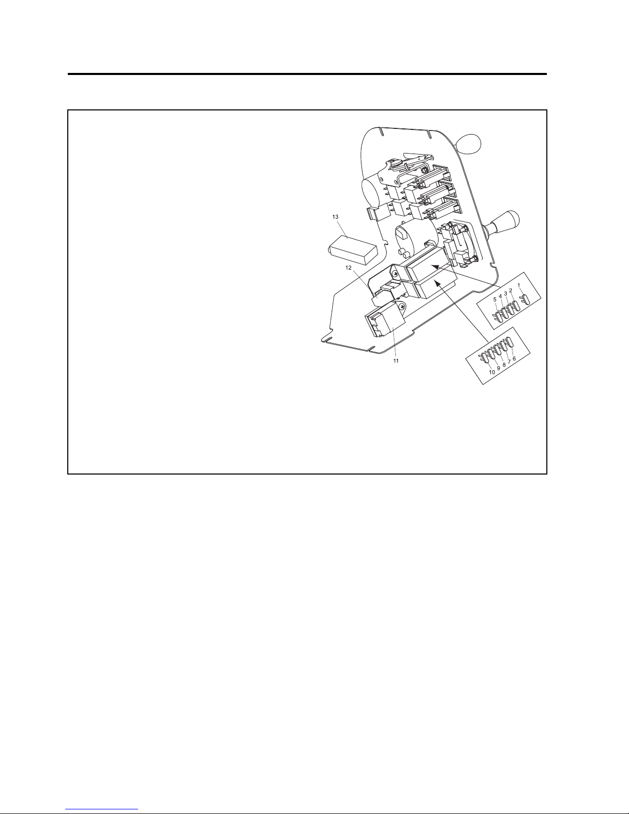
en-70
JACOBSEN AR3
SAFETY, OPERATORS & MAINTENANCE MANUAL
12.4 ELECTRICAL CIRCUIT FUSES AND RELAYS
FUSES & RELAYS
Under Control Panel
1 Fuse - 15 Amp-Start Relay
2 Fuse - 7.5 Amp- Fuel Pump
3 Fuse - 5 Amp - Warning Lamps
4 Fuse - 5 Amp - Warning Lamps
5 Fuse - 10 Amp - Safety Module
6 Fuse - 15 Amp - Accessory Socket 1
7 Fuse - 15 Amp - Accessory Socket 2
8 Fuse - 5 Amp - Warning Lamps
9 Fuse - 5 Amp - Parking Brake
10 Fuse - 2 Amp - Multi-Function Gauge
11 Timer - Glow Plug Lamp
12 Relay - Start
13 Control Module-Safety System Interlocks
12 SCHEMATICS
Page 71
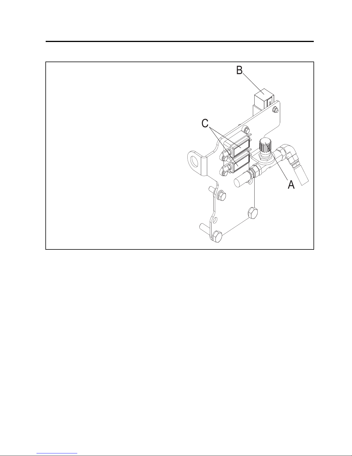
en-71
JACOBSEN AR3
SAFETY, OPERATORS & MAINTENANCE MANUAL
12.4 ELECTRICAL CIRCUIT FUSES AND RELAYS
12 SCHEMATICS
FUSES & RELAYS
In Engine Compartment
B Relay - Glow Plugs
C Strip Fuse - 40 Amp
Top - Cab
Bottom - Glow Plugs
Page 72

en-72
JACOBSEN AR3
SAFETY, OPERATORS & MAINTENANCE MANUAL
13.1 TORQUES
SDAERHTCIRTEMHCTIPESROC
aiD
)mm(
EDARG
6.4
EDARG
8.4
EDARG
8.8
EDARG
9.01
EDARG
9.21
)mN()mN()mN()mN()mN(
656 217112
81151032415
01220
39548001
219325401641571
412628561232872
6169921752263434
02881152205607748
226521433860692511
4252343486802214641
72674536962158712412
036462683271424
28092
332287901391248031073
6392116051210353242805
SDAERHTCIRTEMHCTIPENIF
aiD
)mm(
EDARG
6.4
EDARG
8.4
EDARG
8.8
EDARG
9.01
EDARG
9.21
)mN()mN()mN()mN()mN(
600000
82161235445
0142133688601
212475311951191
417609971252203
61301731472583264
02902972755387049
2218257305755016621
4245327444972313951
72415686173182914132
0351745980913862912
3
334696821275261630434
6369114951981348441835
SDAERHTCNU
)ni(aiD
EDARG
A
EDARG
S
EDARG
T
EDARG
V
EDARG
X
)tf.fbl()tf.fbl()tf.fbl()tf.fbl()tf.fbl(
4/14.32.99.96.212.51
61/
579.814.028.523.13
8/33.215.331.638.545.55
61/77.915.358.752.377.88
2/11.036.1888211531
61/93.34711721161591
8/58.95261571222962
4/360188201
3493774
8/7171464005536967
16525969470592511
8/11363489260174312361
4/111157831794199810032
8/310760281369109427103
2/119884142506230332004
SDAERHTFNU
)ni(aiD
EDARG
A
EDARG
S
EDARG
T
EDARG
V
EDARG
X
)tf.fbl()tf.fbl()tf.fbl()tf.fbl()tf.fbl(
4/18.34.013.113.413.71
6
1/57.78.025.225.825.43
8/39.317.737.046.155.26
61/79.125.952.464.186.89
2/17.335.197.89521251
61/92.84131141971712
8/54.76381791052303
4/
3811913443734925
8/7881905055796548
197275771863015521
8/115049901681140513281
4/113659251056139025352
8/319571602422212828143
2/11699307271
9299632844
13 TORQUES
Page 73

en-73
JACOBSEN AR3
SAFETY, OPERATORS & MAINTENANCE MANUAL
14 GUARANTEE / SALES & SERVICE
GUARANTEE
We GUARANTEE that should any defect in workmanship or material occur in the goods
within TWO YEARS or two thousand hours (on models equipped with hour meters), or
whichever occurs first.
Exception to this warranty will be Aeration products, which are covered for a period of
TWO-YEARS or five hundred hours (on models equipped with hour meters) or
whichever occurs first.
We will repair, or at our option, replace the defective part without making any charge
for labour or for materials, provided that the claim under this guarantee is made through
an authorised dealer and that the de fectiv e part sha ll, if we s o request, be returne d to
us or to the dealer.
This guarantee is in addition to, and does not exclude, any condition or warranty implied
by law, except that we accept no liability in respect of used/second-hand goods, or in
respect of defects which in our opinion are in any way or to any extent attributable to
misuse, lack of reasonable care or ordinary wear and tear, or to the fitting of spares,
replacements, or extra components which are not supplied or approved by us for the
purpose. The use of non-recommended oil or lubricant nullifies the guarantee.
Damage through transport or normal wear does not come under the guarantee.
The warranty is extended to the original purchaser only and is not transferable to
subsequent owners. The warranty period begins on the date the product is delivered
to the end user (customer), unless otherwise agreed with the manufacturer. At the end
of the first year the owner must have the product serviced by an authorised dealer to
be eligible for the second year of warranty coverage.
SALES & SERVICE
A network of authorised Sales and Service dealers has been established and these
details are available from your supplier.
When service attention, or spares, are required for the machine, within or after the
guarantee period your supplier or any authorised dealer should be contacted. Always
quote the registered number of the machine.
If any damage is apparent when delivery is made, report the details at once to the
supplier of the machine.
KEY NUMBERS. It is recommended that all key numbers are noted here:
Starter Switch :-
Fuel tank :-
It is also recommended that the machine and engine numbers are recorded.
The machine serial number is located on the registration plate and the engine serial number can be
found on the rocker cover.
Machine Number :-
Engine Number :-
Page 74

Page 75

Page 76

Ransomes Jacobsen Limited
West Road, Ransomes Europark, Ipswich, IP3 9TT
English Company Registration No. 1070731
www.ransomesjacobsen.com
Jacobsen, A Textron Company
11108 Quality Drive, Charlotte,
NC 28273, USA
www.Jacobsen.com
 Loading...