

Jacobsen 946713, 946714, TURFCAT-T628D 2WD US, TURFCAT-T628D 4WD US Setup And Maintenance Manual

SETUP, PARTS & MAINTENANCE
MANUAL TURFCAT T628D
Model:
946713 TURFCAT-T628D 2WD US
946714 TURFCAT-T628D 4WD US
WARNING: If incorrectly used this machine can cause severe injury. Those who
use and maintain this machine should be trained in its proper use, warned of its
dangers and should read the entire manual before attempting to set up, operate,
adjust or service the machine.
FOR USE WITH OPERATION & SAFETY MANUAL 2722148
2722080 REV02

CALIFORNIA
Proposition 65 Warning
WARNING
Diesel engine exhaust and some of
its constituents are known to the State
of California to cause cancer, birth
defects and other reproductive harm.
Californie Proposition 65
Avertissement
Les échappements des moteurs diesel
et certains de leurs composés sont
reconnus par l’Etat de Californie pour
être cancérigènes, provoquer des
défauts congénitaux et d’autres dangers
en matière de reproduction.
California Advertencia
de la Proposicion 65
The engine exhaust from this product
contains chemicals known to the State
of California to cause cancer, birth
defects or other reproductive harm.
AVERTISSEMENT
L’émission du moteur de ce matériel
contient des produits chimiques que
l’Etat de Californie considère être
cancérigènes, provoquer des défauts
congénitaux et d’autres dangers en
matière de reproduction.
ADVERTENCIA
El estado de California hace saber que
los gases de escape de los motores
diesel y algunos de sus componentes
producen cáncer, defectos de
nacimiento y otros daños en el
proceso de reproducción humana.
© 2002, TEXTRON INC
El estado de California hace saber
que los gases de escape de este
producto contienen productos
quÍmicos que producen cáncer,
defectos de nacimiento y otros daños
en el proceso de reproducción
humana.

Turfcat
T628D
IMPORTANT MESSAGE
Thank you for purchasing this Jacobsen product. You have purchased a world class mowing product, one of the
best designed and built anywhere.
This machine comes with an Operation and Safety Manual and a separate Setup, Parts and Maintenance Manual.
The useful life and good service you receive from this machine depends to a large extent on how well you read and
understand these manuals. Treat your machine properly, lubricate and adjust it as instructed, and it will give you
many years of reliable service.
Your safe use of this Jacobsen product is one of our prime design objectives. Many safety features are built in,
but we also rely on your good sense and care to achieve accident-free operation. For best protection, study the
manuals thoroughly. Learn the proper operation of all controls. Observe all safety precautions. Follow all
instructions and warnings completely. Do not remove or defeat any safety features. Make sure those who operate
this machine are as well informed and careful in its use as you are.
See a Jacobsen dealer for any service or parts needed. Jacobsen service ensures that you continue to receive
the best results possible from Jacobsen’s products. You can trust Jacobsen replacement parts because they are
manufactured with the same high precision and quality as the original parts.
Jacobsen designs and builds its equipment to serve many years in a safe and productive manner. For longest life,
use this machine only as directed in the manuals, keep it in good repair and follow safety warnings and instructions.
You'll always be glad you did.
Textron Golf, Turf & Specialty Products
One Bob Cat Lane
Johnson Creek, WI 53038-0469
TABLE OF CONTENTS ............................................... FIGURES ............................................................................. PAGE
SAFETY .............................................................................................................................................................................. 2
ASSEMBLY AND SETUP ................................................................................................................................................. 3-8
MAINTENANCE .............................................................................................................................................................9-15
FRAME & FRONT AXLE ASSEMBLY ..........................FIGURE 1 ............................................................................. 16, 17
REAR AXLE ASSEMBLY .............................................FIGURE 2 ............................................................................. 18, 19
ENGINE MOUNTING ...................................................FIGURE 3 ............................................................................. 20, 21
LIFT CYLINDER MOUNTING ...................................... FIGURE 4 ............................................................................. 22, 23
RADIATOR MOUNTING .............................................. FIGURE 5 ............................................................................. 24, 25
FUEL SEPARATOR/AIR CLEANER ............................ FIGURE 6 ............................................................................. 26, 27
WING DECK VALVE .................................................... FIGURE 7 ................................................................................... 28
4WD MOTORS W/VALVES .........................................FIGURE 8 ................................................................................... 29
PEDAL CONTROLS .................................................... FIGURE 9 ............................................................................. 30, 31
INSTRUMENT PANEL ................................................. FIGURE 10 ........................................................................... 32, 33
HOOD ASSEMBLY ...................................................... FIGURE11 ............................................................................34, 35
SEAT & PLATFORM ASSEMBLY.................................FIGURE 12 ...........................................................................36, 37
STEERING ................................................................... FIGURE 13 ........................................................................... 38, 39
DRIVE WHEELS & BRAKES ....................................... FIGURE14 ............................................................................40, 41
ELECTRICAL DIAGRAM ............................................. FIGURE 15 ........................................................................... 42, 43
TRACTION ASSIST BRAKES-970211 .........................FIGURE 16 ........................................................................... 44, 45
4WD HYDRAULIC DIAGRAM ..................................... FIGURE 17 ........................................................................... 46, 47
2WD HYDRAULIC DIAGRAM ..................................... FIGURE 18 ........................................................................... 48, 49
4WD HYDRAULIC SCHEMATIC ................................. FIGURE 19 ................................................................................. 50
2WD HYDRAULIC SCHEMATIC ................................. FIGURE 20 ................................................................................. 51
FUEL DIAGRAM ..........................................................FIGURE 21 ........................................................................... 52, 53
MISCELLANEOUS OPTIONS ..................................... FIGURE 22 ........................................................................... 54, 55
DECALS ....................................................................... FIGURE 23 ........................................................................... 56, 57
PUMP-OILGEAR ..........................................................FIGURE 24 ...........................................................................58, 59
HOT OIL SHUTTLE VALVE.......................................... FIGURE 25 ........................................................................... 60, 61
ELECTRICAL SCHEMATIC ......................................... FIGURE 26 ................................................................................. 62
6-2002-TGTSP
1

SAFETY
Turfcat
T628D
NOTICE !!!
Unauthorized modifications may present extreme
safety hazards to operators and bystanders and
could also result in product damage.
Textron Golf, Turf & Specialty Products strongly
warns against, rejects and disclaims any
modifications, add-on accessories or product
alterations that are not designed, developed, tested
and approved by Textron Golf, Turf & Specialty
Products Engineering Department. Any Textron
Golf, Turf & Specialty Products product that is altered,
modified or changed in any manner not specifically
authorized after original manufacture–including the
addition of “after-market” accessories or component
parts not specifically approved by Textron Golf, Turf
& Specialty Products–will result in the Textron Golf,
Turf & Specialty Products Warranty being voided.
Any and all liability for personal injury and/or property
damage caused by any unauthorized modifications,
add-on accessories or products not approved by
Textron Golf, Turf & Specialty Products will be
considered the responsibility of the individual(s) or
company designing and/or making such changes.
Textron Golf, Turf & Specialty Products will vigorously
pursue full indemnification and costs from any party
responsible for such unauthorized post-manufacture
modifications and/or accessories should personal
injury and/or property damage result.
This symbol means:
ATTENTION!
BECOME ALERT!
Your safety and the safety of others is involved.
Signal word definitions:
The signal words below are used to identify levels of
hazard seriousness. These words appear in this
manual and on the safety labels attached to Textron
machines. For your safety and the safety of others,
read and follow the information given with these
signal words and/or the symbol shown above.
DANGER indicates an imminently hazardous
situation which, if not avoided, WILL result in death
or serious injury.
WARNING indicates a potentially hazardous situation
which, if not avoided, COULD result in death or
serious injury.
CAUTION indicates a potentially hazardous situation
which, if not avoided, MAY result in minor or moderate
injury. It may also be used to alert against unsafe
practices or property damage.
SPECIFIC TORQUES:
BLADE BOLT: 70 FT-LBS (95 Nm)
WHEEL HUB NUTS: 300 FT-LBS (407 Nm)
REAR WHEELS: 80 FT-LBS (108 Nm)
FRONT WHEELS: 55 FT-LBS (75 Nm)
2
CAUTION used without the safety alert symbol
indicates a potentially hazardous situation which, if
not avoided, MAY result in property damage
MODEL NUMBER: This number appears on
sales literature, technical manuals and price lists.
SERIAL NUMBER: This number appears only
on your mower. It contains the model number
followed consecutively by the serial number. Use
this number when ordering parts or seeking
warranty information.

Turfcat
T628D
All references to "right" or "left" or
"front" or "rear" are with respect to an
operator in the tractor seat.
TRACTOR ASSEMBLY
1. STEERING WHEEL ATTACHMENT
– Attach the steering wheel to the shaft by lining up
hole R in steering wheel with hole in shaft.
– Insert roll pin.
ASSEMBLY AND SETUP
2. TRACTOR WHEEL ATTACHMENT
a) Attach the tractor wheels to the hubs.
b) Torque the front wheel bolts to 55 ft-lbs (75 Nm)
and the rear wheel lug nuts to 80 ft-lbs (108 Nm).
NOTE - Check lug nut torque after the first 10 hours
of use and adjust if not still within the initial range.
3

ASSEMBLY AND SETUP
3. SEAT ATTACHMENT
a) Spring suspension seat
– Make sure the seat is bolted securely to the
suspension spring.
– Bolt the suspension spring securely to the center
of the seat plate using hardware provided in the
tractor loose parts bag.
– Locate the two plastic clips and attachment
hardware in the tractor loose parts bag. Attach
the clips to the bottom of the seat plate and
secure with the throttle cable passing through the
clips as shown.
Turfcat
T628D
b) Deluxe suspension seat
– Drop the four bolts at the base of the seat
suspension into the corresponding holes in the
seat plate.
– Locate the two plastic clips in the tractor loose
parts bag. Place these two clips on the front two
seat bolts protruding through the seat plate,
guiding the throttle cable through them as shown.
Secure all four seat bolts with the nuts provided.
c) Seat Switch (either seat) - Route the seat switch
cable up through the hole in the seat plate and
attach to the connector at the base of the seat.
4. Tractor and deck tire pressures should be 14 p.s.i. (1 kg/cm
5. Check battery electrolyte level and charge. Use protective equipment such as, but not limited to, goggles,
face shield, rubber gloves, and apron.
2
Deluxe Suspension Seat
Bottom side of seat plate
). Adjust if necessary.
6. Before starting the machine:
– Fill the fuel tank with diesel fuel.
– Top up the engine sump with lubricating oil if low.
– Top up the radiator with a 50% antifreeze solution if low.
– Top up the hydraulic system with oil if low.
– Lubricate at designated points (refer to the lubrication section in this manual).
– Read and understand the Operation & Safety manual, paying particular attention to the safety, control and
operation information.
4

Turfcat
ASSEMBLY AND SETUP
T628D
CUTTERDECK ASSEMBLY
1. CASTER WHEELS
a) Uncrate the deck. Remove the casters from deck mounting plates P. Reassemble to the mounting plates
with reference to the height of cut chart on the deck cover or in the cutterdeck section of this manual.
b) Place blocks under the rear of the deck so that the bottom edge is approximately parallel with the ground.
Caster mounted in "HIGH" position
2. PREPARING THE TRACTOR
a) Start the tractor. Push the lift lever forward to fully extend the deck chains. Stop the engine.
b) Line up a push arm at the inside of the tractor's axle mounting bracket, making sure arm J is offset to the
outside of the tractor and the lubrication fitting at the deck end of J faces upward. Attach to the bracket
with the head of a 5/8" bolt on the inside and lockwasher and nut on the wheel side. Tighten securely.
Repeat for other push arm.
c) Identify the 5/8" hose marked "PRESSURE" and attach the opposite end of that hose to the fitting on valve
V identified "PRESSURE". Match and attach the same way with the hose marked "RETURN". Tighten
both connections securely. Have drip pan ready to catch oil seepage.
5

ASSEMBLY AND SETUP
Turfcat
T628D
3. ATTACHING DECK TO TRACTOR
a) Remove the deck belt cover.
b) Place the deck square to and approximately 2" in front of the tractor's front wheels.
c) Run the two 5/8" hoses straight out from the tractor valve (do not cross) to the deck motor "PRESSURE"
and "RETURN" fittings. Connect these hoses with the fittings angled upward to make it easier to attach the
push arms to the deck. Leave connections snug but not tight. They will be repositioned and securely
tightened later in the setup procedure.
d) Line up the front pivot of the two push arms inside the deck hanger brackets, insert both pins P and secure
with (2) 5/16-18 X 7/8 bolts and (2) 5/16-18 nuts.
Deck motor hose attachment Push arm attachment
4. SAFETY CHAINS
a) Verify that the bottom link of the deck chains
reach the deck bracket mounting holes. If not, the
deck cylinder may need to be further lowered with
the tractor lift lever or the chains checked for
routing problems.
b) Anchor the bottom link of each chain to the
bracket with 5/16-18X1-1/4" bolts and washers,
first making sure the chains drop straight without
twisting. Secure with locknuts.
6

Turfcat
T628D
5. SECURING DECK HOSES
a) Attach the 3/8" drain line hose to the top case
drain port of the deck motor, with the hose angled
straight back toward the tractor (not arched right
or left). Tighten securely. Tie the 3/8" hose at B
on the center 90o hose end fitting of deck valve V.
b) Rotate both 5/8" hose fittings so the hoses slope
downward and clear the rear of the motor plate by
approximately 1/4". Tighten both fittings on the
motor securely.
c) Before tightening the 5/8" hoses on their fittings,
push them down along their entire length. Then
place a wrench on a hose and another wrench on
the connection to the fitting. Turn the hose
wrench approximately 1/16 of a turn, opposite the
direction the fitting connection will be tightened.
Hold the hose in that position while tightening the
fitting connection securely. Repeat for the other
5/8" hose. This is an important step to prevent the
hoses from loosening as the deck tips up and
down at the left and right ends while mowing over
undulating ground, or movement during transport.
ASSEMBLY AND SETUP
6. HOSE VERIFICATION
a) Raise the front axle of the tractor until the deck will not touch the ground when fully lowered. Check deck
hoses in this position and in the fully raised position. Readjust if necessary using the procedures above so
that the hoses do not rub in any deck position on the tractor or deck.
b) When satisfied with hose adjustment, replace the deck belt cover.
7. HEIGHT ADJUSTMENT PINS
a) Identify with reference to the height of cut chart
on the deck belt cover or in the cutterdeck section
of this manual the desired hanger pin location.
b) With the cutterdeck slightly raised, insert an
adjustment pin in the same location for each
hanger.
7

ASSEMBLY AND SETUP
8. WEIGHT TRANSFER SPRINGS
Secure the weight transfer springs as follows to allow
them to rotate during normal deck operation:
a) Start the engine and fully raise the deck. Support
it by hooking the deck latch to the frame floor
board. Stop the engine.
b) Spring Top - For each of the two 3/8-16 x 1-1/2"
bolts, run a flanged nut to the end of the threads,
which leaves a shank section exposed. Hook one
end of a spring over the shank of each bolt. Insert
the bolts from the inside of bracket BT toward the
front of the tractor. Secure each bolt with another
flanged nut on the outside.
c) Spring bottom - Assemble large washer W and
spacer R on each of the two 3/8-16 x 1" bolts.
Place the hook on the other end of each spring
over the spacer. Insert the bolts into brackets BB
facing inward and secure each on the inside
surface with a flanged nut.
d) Slightly lift the deck to release the deck latch.
Rotate it downward out of the way.
Turfcat
T628D
Finished installation
9. LUBRICATE
FRONT
INSIDE
– Lubricate the fittings at the deck end of the two deck push arms.
8

Turfcat
T628D
MAINTENANCE
2-WHEEL2-WHEEL
Numbers above show service locations in accompanying chart.
SDIULF YTITNAUQ EPYT
Arrows show lubrication points.
LIOENIGNE
LIOCILUARDYH
TNALOOCROTAIDAR
)sretil3.3(snollag88.0DC-FS03W01
)sretil7.52(snollag8.6DC-FS03W01
)sretil4.6(snollag7.1EZEERF-ITNA%05
9

MAINTENANCE
Turfcat
T628D
Verify proper adjustment of cutterdeck belts regularly during the first 5, 10 and 15 hours of operation.
After first 50 hours of operation, replace engine oil, hydraulic oil and related filters.
sruohesehT.bojemit-enoasiecivresoN
.ecivresHCAEneewtebslavretniera
NETFOEROMECIVRES
.SNOITIDNOCYTRIDREDNU
NOITAREPOFOSRUOH
SMETIECIVRES
metsySkcolretnIkcehCX
)1(leveLliOenignEpu-poT/kcehCX
)5(leveLliOciluardyHkcehCX
)7(leveLtnalooCpu-poT/kcehCX
)6(rotarapeSretaWkcehCX
erusserPeriTkcehCX
enignEnaelC/kcehC
neercS&rotaidaR,tnemtrapmoC
rotcelloCelcitraPrenaelCriAnaelCX
noisneTtleBkceDrettuCyfireVX
sgnittifesaergetacirbuL keewyrevE
)2(tnemelErenaelCriAecalpeR
YLIAD05001004006
X
srh004yrevE
)snoitidnocgnitarepoytridrofrenoos(
yrettaBpu-poT/kcehCX
ssenthgiTrenetsaFkcehCX
noisneTtleBnaFkcehCX
)3(retliF&liOenignEegnahCX
)4(retliF&liOciluardyHegnahC X
)8(sretliFleuFegnahC X
ni-eoTleehWraeRkcehC X
knaTleuFnaelC&niarD X
10
launaMenignErePenignEecivreS X
)9(metsySgnilooChsulF&niarD X
)margaidnosmetiecivresetacolsrebmungniliarT(

Turfcat
T628D
CLEAN MACHINE
– The cooling system must be checked and
cleaned daily to prevent engine overheating
(more often under especially dirty conditions).
Clean the radiator, oil cooler and radiator screen
S of any grass chaff or debris using compressed
air or low pressure water (garden hose). Do not
use high pressure water - damage to radiator or
oil cooler may result.
– When washing machine with pressure spray or
steam cleaners, avoid washing bearing areas.
Cleaning solutions may penetrate bearing seals
and cause premature bearing failure.
HYDRAULIC SYSTEM
MAINTENANCE
– Check hydraulic fluid level in the reservoir sight
glass. Normal level is approximately in the
center.
– Every 400 working hours, change the hydraulic
fluid and filter. The fluid is drained from a capped
port located near the bottom of the reservoir. The
filter is a spin-on cannister type.
BATTERY MAINTENANCE
Check battery fluid level periodically. If low, top up
with distilled water. When working with battery fluids,
always use protective equipment, such as, but not
limited to, goggles, face shield, rubber gloves, and
apron.
11

MAINTENANCE
ENGINE OIL
See Engine Manual for manufacturer's
recommendations. Before using the machine for the
first time, check the oil level in the engine crankcase
with the crankcase dipstick. When checking oil level,
make sure the machine is on level ground.
To change engine oil:
1. First warm up the engine. Shut off engine when
warm, remove oil drain plug P and drain the oil
from the sump.
2. Clean plug and replace.
3. Re-fill sump with the recommended engine oil.
4. Always check level of oil on the dipstick. To
obtain the correct measurement, the machine
should be on level ground.
Turfcat
T628D
NOTE: After the oil has been added, wait one minute
and then check level of oil again with the dipstick.
To change engine oil filter:
The oil filter cartridge O is easily reached from the
right side of the tractor. It should be replaced
complete with each oil change. Apply a thin film of oil
to the seal when replacing the cartridge and check for
leaks after starting the engine. Top off oil if
necessary.
AIR CLEANER
Clean and replace the air cleaner element as
specified in the service chart. Uneven running, lack of
power or black exhaust fumes may indicate a dirty air
cleaner.
To replace air cleaner element:
1. Unclamp end cover Y and remove existing
cleaner element.
2. Insert new element Z and replace end cover.
Ensure arrows on end cover are pointing
vertically upwards.
12

Turfcat
T628D
WATER FUEL SEPARATOR
The machine is equipped with a water fuel separator
that traps water in the fuel. If the water is not removed
from the fuel system, extensive damage can occur in
the fuel injection system.
Water will collect at the bottom of the see-through
bowl A and appears a different color than the fuel.
Remove the water as follows:
1. Drain water by opening the self-venting drain
valve B and allowing all water to escape.
Re-tighten drain valve.
2. The entire water separator assembly can be
removed by turning counterclockwise while
gripping black grip C
NOTE: Always bleed the fuel system of air after
removing the water from the separator.
MAINTENANCE
MAINTENANCE
R
13

MAINTENANCE
BLEEDING AIR FROM FUEL
If any service has been performed on the fuel
manager water separator or fuel filter, first purge air
from the fuel manager (Steps 1-3) otherwise skip to
Step 4.
1. Loosen the air vent D one to two turns.
2. Fully depress hand primer pump plunger E until
all air has escaped.
NOTE: Step 2 may take up to 60 pumps.
3. Close the air vent D.
4. Bleed the air in the fuel lines from the fuel
manager to the injector pump by loosening the air
vent bolt F on the injector pump.
5. Set the parking brake.
6. Turn the keyswitch, cranking the engine until all
air has escaped. Turn keyswitch to the off
position.
7. Tighten the air vent bolt F.
Turfcat
T628D
HAND PRIMER PUMP
The hand primer pump is used to purge air from the
fuel system. The entire pump assembly is
replaceable if necessary. See parts section for
service parts.
1. Remove the small black retaining ring H carefully
as it is spring loaded.
2. Remove hand pump components and replace
with new components
14

Turfcat
T628D
FUEL FILTER
1. To change the fuel filter only, first remove the
see-through water separator bowl. See water
fuel separator procedure on the previous page.
2. Remove the large black retaining ring G.
3. Pull the filter element straight down. Do not twist
as the filter element is not threaded.
4. Dispose the old filter element according to local
laws.
5. Align key in filter element with the slot in the
header and push the new filter element up into
the filter head.
6. Place retainer ring G. Hand tighten retainer ring
until it clicks and the arrows line up in the center
of the header.
MAINTENANCE
NOTE: Always bleed the fuel system of air after
changing the fuel filter.
COOLANT
The quantity of fluid in the coolant system is indicated
by the fluid level in overflow bottle O.
– Keep the overflow bottle approximately 1/4-1/2
full.
– When filling, use a 50/50 mixture of antifreeze
and water.
HYDRAULIC NOTES
– Lower implements attached to lift arms to relieve hydraulic pressure from system before servicing.
– When servicing hydraulic pipe fittings, do not use teflon tape. Use a liquid sealant that will dissolve into
the system.
– Make sure all hydraulic connections are tight before applying pressure to system.
When checking for leaks, do not use your hands to attempt to feel a spray. Instead, pass an object like
cardboard over hydraulic system components to visualize a spray. Escaping hydraulic fluid can be under
sufficient pressure to penetrate skin and cause serious injury. If injured by escaping hydraulic fluid, see a
doctor at once. Serious infection or reaction can develop if proper medical treatment is not administered
immediately.
15

FRAME & FRONT AXLE ASSEMBLY
Turfcat
FIGURE 1
T628D
16

Turfcat
FRAME & FRONT AXLE ASSEMBLY
T628D
ITEM PART NO. DESCRIPTION QTY
1-1 2721872 S-FRAME RAIL RH 1
1-2 2196132.6 WLDMT-REAR FRAME 1
1-3 2721873 S-FRAME RAIL LH 1
1-4 2721874 S FRAME FRONT W/LABS 1
1-5 2196134.6 WLDMT-FRONT AXLE 1
1-6 64250-04 INSERT M8 2
(USE QTY 3 ON 2WD)
(USE INSERT TOOL 2196247)
1-7 64205-026 BLT-MET M8-1.25X80 2
1-8 A1105061 BOLT-M12-1.75X30 4
1-9 64251-005 WASHER-M12 8
1-10 64237-06 LOCKNUT-NYLON M12-1.75 8
1-11 64205-036 BOLT-MET M10-1.50X35 2
1-12 48517-05 HOLE-PLUG .515 2
1-13 A110406 SCREW M10-1.5X30 10
1-14 64251-004 WASHER-M10 24
1-15 64237-03 LOCKNUT-NYLON M10-1.5 12
1-16 64018-16 BLT-CARRIAGE 1/2-13X5 2
(USE ON 2WD ONLY)
2722080-1
FIGURE 1
ITEM PART NO. DESCRIPTION QTY
1-17 48517-02 HOLE PLUG .625 1
(USE ON 2WD ONLY)
1-18 64251-003 WASHER-M8 2
1-19 2721055 DECK VALVE 1
1-20 108138-02 CABLE CLIP 1
(USE ON 2WD ONLY)
1-21 64205-003 BLT-MET M8-1.25X30 1
(USE ON 2WD ONLY)
1-22 2192586.7 BUMPER 1
1-23 2192304.7 WEIGHT 9
(USE ON 2WD ONLY)
1-24 64205-029 BLT-MET M12X1.75X40 4
1-25 64229-05 LOCKNUT-NYLON 1/2-13 2
(USE ON 2WD ONLY)
1-26 64006-02 LOCKWASHER-HEL 5/16 1
17

REAR AXLE ASSEMBLY
Turfcat
FIGURE 2
T628D
18

Turfcat
REAR AXLE ASSEMBLY
T628D
ITEM PART NO. DESCRIPTION QTY
2-1 64205-007 BLT-MET M10-1.5X20 2
2-2 800488 LOCKWASHER M10 2
2-3 64163-17 25/64X2X11 GA WSHR 2
2-4 62464-4A WASHER-THRUST 4
2-5 108003 BUSHING 6
2-6 2721223 THRUST BEARING 2
2-7 173042 SPACER-SPINDLE 2
2-8 64123-72 BLT-HEX 1/2-13X2-1/2 1
2-9 64163-19 WASHER 3
2-10 2203049 BUSHING STEERING CYL 1
2-11 64229-05 LOCKNUT-1/2-13 1
2-12 4118238 CYL-HYDRAULIC STEERING 1
(USE SEAL KIT 4118238-01)
2-13 800490 NUT-14 MM -1.5 1
2-14 2721183 END-TIE ROD 1
(INCLUDES ITEM 37)
2-15 48479 S DUST COVER 1
2-16 64251-006 WASHER
(USE QTY 2 ON 4WD)
(USE QTY 4 ON 2WD)
2-17 2193045.7 TIE ROD 1
2-18 64025-27 NUT 5/8-18 LH 1
2-19 64140-5 COTTER PIN-1/8X1-1/2 2
2-20 148058-02 ROD END LH 1
(INCLUDES ITEM 37)
2722080-2
FIGURE 2
ITEM PART NO. DESCRIPTION QTY
2-33 85010N ZERK 1/4-28 STR 7
2-34 35027N ZERK FITTING 1
2-35 2196145.2 WLDMT-REAR AXLE 1
2-36 64197-001 BLT-TR 5/16-18X3/4 4
2-37 64025-30 NUT 1/2-20 SLOT 3
2-38 2206030.7 WLDMT-REAR AXLE PIVOT 1
2-39 64151-29 NUT-HEX 1 1/4-12 NYLK 1
2-40 2721185.7 WLDMT-WHL SPNDL,R 2
2-41 2198231 WHEEL ASM, 18 X 8.5 2
2198209-02 RIM ASSEMBLY A/R
2198231-01 TIRE-18X8.5 RIB TR A/R
(USED ON 2WD)
2-42 2722072.7 BRKT-HOSE BRACE LH 1
2-43 * 2722073.7 BRKT-HOSE BRACE RH 1
2-44 48476-A1 HUB ASM 2
(INCLUDES ITEMS 15,33,45-47)
2-45 48480 SEAL 1
2-46 48043-03C S CUP,OUTER BRG 2
2-47 48043-04C S CONE,OUTER BRG 2
2-48 64163-26 WASHER,.766 ID X 1.625 4
2-49 64025-20 NUT-HEX 3/4-16 SLOT U 2
2-50 4114180-01 MOTOR-WHEEL W/CHECK 1
(INCLUDES ITEM 51)
(SEE FIGURE 8 FOR SERVICE PARTS)
2-51 64164-08 S-KEY WHEEL MOTOR 2
2-21 2721146.7 PLATE-MOTOR 2
2-22 2720828.7 WLDMT-WHEEL HUB 2
2-23 64025-35 NUT-1-1/8-18 UNSLOT TRW 2
2-24 A1005166 BLT-MET M12-1.75X80 8
2-25 64140-1 COTTER PIN 1/8X1 3
2-26 64006-05 LOCKWASHER 1/2 8
2-27 64207-07 NUT-HEX M12-1.75 8
2-28 2721416-01 WHL MTR-CA012W/VALV 1
(INCLUDES ITEM 51)
(SEE FIGURE 8 FOR SERVICE PARTS)
2-29 148058-01 ROD END RH 1
(INCLUDES ITEM 37)
2-30 64025-16 NUT-5/8-18 RH 1
2-31 2198209 WHL ASM 18X8.5-8 4 PLY 2
2198209-01 S TIRE 18X8.5-8 4 PLY A/R
2198209-02 S RIM 8 4 BLT A/R
(USED ON 4WD)
2-32 64187-03 WHEEL NUT 1/2-20 8
*NOT ILLUSTRATED
19

ENGINE MOUNTING
Turfcat
FIGURE 3
T628D
20

Turfcat
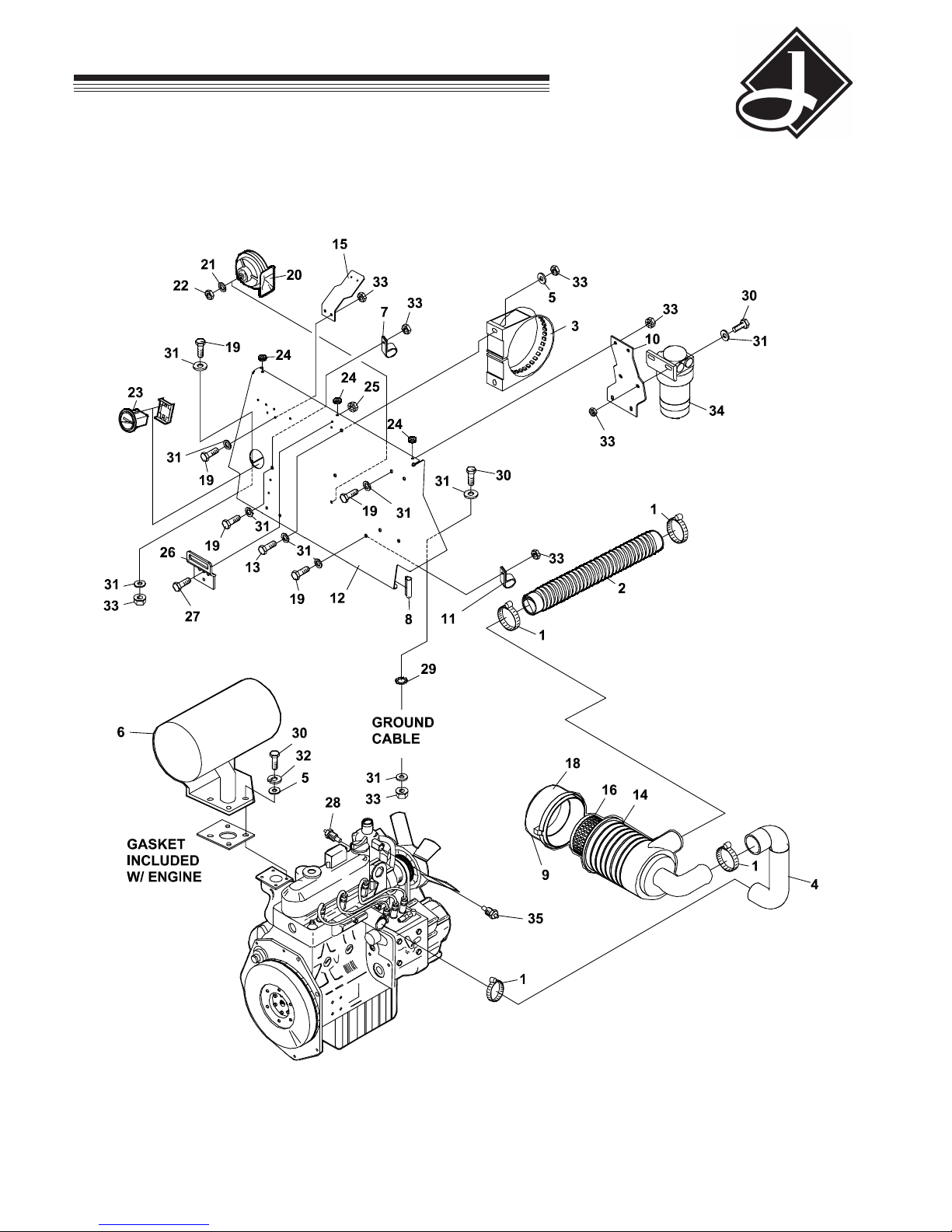
ENGINE MOUNTING
T628D
ITEM PART NO. DESCRIPTION QTY
3-1 2721362.7 MOUNT-ENGINE, LF/RR 2
3-2 2721429.7 MNT-ENGINE RH 1
3-3 * 2721457 ENG-KUBOTA D1105-EB 1
3-4 2198132 MOUNT-ISOLATION 4
3-5 2721428.7 MOUNT-ENGINE LH 1
3-6 2721459.7 BRKT-HOSE MNT LH 1
(USE ON 4WD ONLY)
3-7 2721460.7 BRKT-HOSE MNT RH 1
(USE ON 4WD ONLY)
3-8 2721363.7 MOUNT-ENGINE, RF/LR 2
3-9 2208048-02 FLANGE KIT 1
3-10 128079 ROD END 1/4 FEMALE 1
3-11 148057-01 CABLE-THROTTLE 1
3-12 172084 SWIVEL-CABLE CLAMP 1
3-13 64123-105 BLT-HEX 1/4-20 X 1-5/8 1
3-14 64206-04 BLT-MET M10-1.25X25 1
3-15 64205-007 BLT-MET M10-1.5X20 8
3-16 64205-019 BLT-MET M10-1.5X80 4
3-17 2208048-01 BELL HOUSING 1
3-18 64237-03 LOCKNUT-NYLON M10-1.5 20
3-19 64251-003 WASHER-M8 2
3-20 64205-027 BLT-MET M10-1.5X40 8
3-21 64251-004 WASHER-M10 24
3-22 64229-01 LOCKNUT-NYLON 1/4-20 1
3-23 64163-27 WASHER 8
3-24 4113994.7 BRKT-THROTTLE 1
3-25 22372 CABLE-CLAMP 1
3-26 64152-49 #10-24X3/4 MACH SCRW 1
3-27 64025-15 NUT-HEX #10-24 KEPS 1
3-28 64206-08 BOLT-M10-1.25X25 8
3-29 800488 LOCKWASHER-M10 9
3-30 2198187 COUPLING-13 TOOTH 1
3-31 2208048 ASSY BELL HOUSING 1
3-32 4114576 PUMP-OIL GEAR 1
3-33 2721334 PUMP-HYDRAULIC 1
3-34 64123-70 BLT-HEX 3/8-16X1-1/2 2
3-35 64006-03 LOCKWASHER 3/8 2
3-36 64123-117 BLT-MET M12-1/2-13X1-1/2 2
3-37 64251-005 WASHER-M12 2
3-38 64250-02 INSERT-M6 2
(USE INSERT TOOL 2196246)
2722080-3
FIGURE 3
ITEM PART NO. DESCRIPTION QTY
3-44 64237-05 LOCKNUT-NYL M8-1.25 6
3-45 A1103051 BOLT-M8-1.25X25 3
3-46 2192444.7 BRKT-NEUTRAL CONTROL 1
3-47 64123-162 BLT-HEX 5/16-24X5 1
3-48 2193046 BUSHING 1
3-49 2198279 SPRING-COMPRESSION 1
3-50 123032 BUSHING 1
3-51 64151-24 HEX CL NUT 5/16-24 2
3-52 64025-03 NUT-HEX 5/16-24 1
3-53 48244A BALL JOINT 5/16F W/STUD 1
3-54 64061-28 ROLL PIN-3/16X1-1/4 1
3-55 2196133.7 WLDMT-CONTROL ARM 1
3-56 64205-015 BOLT-M8-1.25X35 1
3-57 64163-55 WASHER 1
3-58 64123-59 BLT-HEX 5/16-24X1/2 1
3-59 48228-10 CLIP-INSUL 1.75 CABLE 1
3-60 64205-018 BLT MET M8-1.25X15 1
3-61 64205-003 BLT-M8-1.25X30 1
3-62 2722141.7 BRKT-HOSE 1
(USE ON 4WD ONLY)
3-63 148090-03 HOSE-SUPPORT 5/8 4
3-64 64123-60 BLT-HEX 1/4-20 X 2 1
3-65 64163-03 WASHER 3
* AVAILABLE THROUGH KUBOTA DEALER.
3-39 64250-04 INSERT-M8 A/R
(USE QTY 4 ON 2WD & QTY 3 ON 4WD)
(USE INSERT TOOL 2196247)
3-40 158061-24 O-RING 1
3-41 64123-224 BOLT-HEX 1/4-20X1 1
3-42 2192505.7 BRKT-CONTROL CABLE 1
3-43 128089-02 CABLE, CONTROL 1
21

LIFT CYLINDER MOUNTING
Turfcat
FIGURE 4
T628D
22

Turfcat
LIFT CYLINDER MOUNTING
T628D
ITEM PART NO. DESCRIPTION QTY
4-1 198042 VALVE-HYDRAULIC 1
(USE SEAL KIT 198042-01)
4-2 68156A HANDLE-KNOB, BLACK 1
4-3 64001-06 JAM NUT-3/8-16 1
4-4 2196138.7 WLDMT-LIFT LEVER 1
4-5 192087.7 BRKT-LIFT PIVOT MNT 1
4-6 64141-6 NUT-WLF 5/16-18 4
4-7 64163-31 WSHR-25/64X12 GA 2
4-8 64123-16 BLT-HEX 3/8-16X1 14 2
4-9 64151-15 5/16-18 HEX HD CL 4
4-10 2196215 S-PULLEY-MOUNT BRKT 1
4-11 2192291.7 SHIM-CYL SUP BRKT 4
4-12 2192289.7 BRKT-CYL SUPPORT 2
4-13 64139-08 BLT-WLF 5/16-18X3/4 8
4-14 192086.7 GUIDE-CHAIN 4
4-15 196004 PULLEY-CHAIN 2
(INCLUDES 198003-01 BEARING)
4-16 62464-3A THRUST-WASHER 2
4-17 64061-07 ROLL PIN 5/32X1-1/4 2
4-18 2198127 TUBE-SPACER 2
4-19 64061-15 ROLL PIN 1/8X1/2 2
4-20 108031 BRG-FLANGE NOTCHED 2
4-21 64151-18 NUT-HEX CL 3/8-16 2
4-22 64151-17 NUT-HEX CL 1/4-20 1
4-23 193003 SHAFT-PULLEY MNTNG 1
4-24 4118636 CYLINDER-LIFT 1
(USE SEAL KIT 4118636-01)
2722080-4
FIGURE 4
ITEM PART NO. DESCRIPTION QTY
4-25 2193027 SHAFT-CYL PIVOT 1
4-26 2193028 PIN-LOCKING 1
4-27 64163-34 WSHR-FLT.256IDX11 GA 1
4-28 64123-224 BOLT-HEX 1/4-20X1 1
4-29 192187.7 BRKT-TUBE SUPPORT 1
4-30 64141-2 NUT-WLF 1/4-20 4
4-31 64139-04 BLT-WLF 1/4-20X3/4 4
4-32 148062 MASTER LINK #50 CHAIN 1
4-33 64205-023 BOLT-M6-1.0X50 2
4-34 64006-01 LCKWSHR-HELICAL 1/4 2
4-35 198003-01 BEARING-OILITE 2
4-36 48228-07 CLIP-CABLE 1
23

RADIATOR MOUNTING
Turfcat
FIGURE 5
T628D
24

Turfcat
RADIATOR MOUNTING
T628D
ITEM PART NO. DESCRIPTION QTY
5-1 64205-018 BLT-MET. M8-1.25X15 8
5-2 64251-003 WASHER-M8 32
5-3 2178211-01 RADIATOR CAP 1
5-4 64237-05 LOCKNUT-NYL M8-1.25 20
5-5 64246-01 NUT-M6 WIZ NUT 4
5-6 142350-02 BRKT-RECOVERTANK RH 1
5-7 142350-01 BRKT-RECOVERTANK LH 1
5-8 BOTTLE-OVERFLOW 1
(SEE KUBOTA ENGINE MANUAL)
5-9 2721697.6 WLDMT-RADIATOR PANEL 1
5-10 118047-06 BUSHING FLIPLOCK .31 ID 2
5-11 2198175 SCREEN 1
5-12 2721565.7 COVER-OIL COOLER 1
5-13 108194-06 CHANNEL FLEX TRIM 21.0 1
5-14 2198084 LATCH-SWELL 4
5-15 2721876 S REAR PANEL W/LABS 1
5-16 2721586 MOUNT-OIL COOLER 2
5-17 48383 CLAMP-HOSE 2 1/2 DIA 2
5-18 A1102966 BLT-MET. M6-1.0X16 4
5-19 64139-20 BLT-WLF M6-1.00X16 8
5-20 2198174 RADIATOR 1
(INCLUDES ITEM 3)
2722080-5
FIGURE 5
ITEM PART NO. DESCRIPTION QTY
5-44 108194-11 FLEX TRIM X 16.5 1
5-45 108194-06 FLEX TRIM X 13.0 1
5-46 48228-1A CLIP-CABLE 1
5-47 48517-05 PLUG-HOLE .515 3
5-48 2721906 CABLE TIE-PUSH MOUNT 2
5-21 2721536 OIL COOLER 1
5-22 64006-02 LOCKWASHER-HEL. 5/16 8
5-23 64251-002 WASHER M6 8
5-24 108094-01 CLAMP 4
5-25 2721519 HOSE-RAD LOWER 1
5-26 2721511 HOSE-RAD UPPER 1
5-27 2192440.7 MOUNT-RAD RH 1
5-28 108194-13 CHANNEL-FLEX TRIM 39.0 1
5-29 2192439.7 MOUNT-RAD LH 1
5-30 108194-11 CHANNEL-FLEX TRIM 17.0 2
5-31 64205-001 BLT-MET. M8-1.25X20 16
5-32 48256 PLUG-HOLE 2
5-33 2721875 S-FAN SHROUD 1
5-34 198069-02 HOSE-AIR CLNR INTAKE 1
5-35 2192441.7 SCREEN GUIDE 2
5-36 2721566.7 COVER-OIL COOLER 1
5-37 64229-01 NUT-1/4-20 4
5-38 64237-02 LOCKNUT-NYL M6-1.0 4
5-39 64163-03 WASHER 4
5-40 64018-2 BLT-CRG 1/4-20X3/4 4
5-41 2721397.7 BRKT-FAN SHROUD 1
5-42 2721395.7 MOUNT-RADIATOR LH 1
5-43 64250-02 INSERT-GRIP M6-1.0 4
(USE INSERT TOOL 2196246)
25
FUEL SEPARATOR/AIR CLEANER
Turfcat
FIGURE 6
T628D
26

Turfcat
FUEL SEPARATOR/AIR CLEANER
T628D
ITEM PART NO. DESCRIPTION QTY
6-1 48383 CLAMP HOSE 2-1/2 DIA 4
6-2 198069-02 S-HOSE AIR CLEANER 1
6-3 2198297 CLAMP-AIR CLEANER 1
6-4 2721526 HOSE-AIR CLEANER 1
6-5 64163-29 WASHER 4
6-6 2208033 MUFFLER-EXHAUST 1
6-7 48228-1A CABLE CLIP 1
6-8 64163-29 WASHER 2
6-9 2198147-04 S COVER CLIP A/R
6-10 2721829.7 BRKT-FUEL MANAGER 1
6-11 48228-06 CLIP-CABLE 2
6-12 2721524.7 PANEL-FRONT 1
6-13 64205-015 BOLT 2
6-14 2198147 AIR CLEANER 1
(INCLUDES ITEMS 9,16, 17, & 18)
6-15 2722219.7 BRKT-MNT, RELAY 1
6-16 2198147-01 ELEMENT A/R
6-17 * 2198147-02 VALVE-DUST UNLOAD A/R
6-18 2198147-03 COVER A/R
6-19 64205-001 BLT-MET M8-1.25X20 12
6-20 886425 HORN 1
6-21 64006-01 LOCKWASHER 1/4 1
6-22 64207-06 NUT-HEX M6-1.0 1
6-23 48030N HOUR METER ASSY 1
6-24 2198125 BUMPER 3
6-25 64025-29 NUT-HEX #8-32 KEPS 2
6-26 4113647.7 BRKT-LATCHING PLATE 1
6-27 64152-20 8-32X 1/2 MACH SCREW 2
6-28 148270 TEMPERATURE SENDER 1
6-29 64002-04 LOCKWASHER-TOOTH EXT 1
6-30 A1103051 BOLT-M8-1.25X25 7
6-31 64251-003 WASHER-M8 25
6-32 64006-02 LOCKWASHER-HEL 5/16 4
6-33 64237-05 LOCKNUT-NYLON M8-1.25 17
6-34 2721539 FUEL MGR 1
2721539-01 S-FILTER 3.6" 5 MICRON 1
2721539-02 S-BOWL ASSEMBLY 1
2721539-03 S-HAND PRIMER ASSY 1
2722080-6
FIGURE 6
ITEM PART NO. DESCRIPTION QTY
6-35 2722389 SWITCH-TEMP 1
*NOT ILLUSTRATED
27

WING DECK VALVE
Turfcat
FIGURE 7
2722080-7
T628D
28

Turfcat
4WD MOTORS W/VALVES
T628D
2722080-8
4WD MOTORS W/VALVES
FIGURE 8
29

PEDAL CONTROLS
Turfcat
FIGURE 9
T628D
30

Turfcat
PEDAL CONTROLS
T628D
ITEM PART NO. DESCRIPTION QTY
9-1 64139-02 BLT-WLF 1/4-20X1/2 10
9-2 4117819 BRG-PILLOW BLOCK, 1/2 2
9-3 4114282 S HEEL SUPPORT W/MATS 1
9-4 810149 BUMPER-RUBBER 1
9-5 4118926 S FWD/REV PEDAL W/MAT 1
9-6 64044-1 SET SCREW 1/4-20 X 1/4 4
9-7 2721878 S INST PANEL W/LABS 1
9-8 43067A COLLAR, SET PLATE 2
9-9 2721879 S TOWER CVR W/LABS 1
9-10 4114249 WLDMT-NEUTRAL CONTRL 1
9-11 48429 SPRING-EXTENSION 1
9-12 48428 COLLAR SET, 3/8 ID 2
9-13 64025-15 NUT-HEX 10-24 KEPS 4
9-14 108208 SWITCH-NCNC DBL POLE 1
9-15 64152-06 10-24 X 1/2 MACH SCRW 2
9-16 128079 ROD END 1/4 FEMALE 2
9-17 2198294 GAUGE-FILTER VACUUM 1
9-18 2690032-01 FTG-90 STREET EL 1
9-19 128089-02 CONTROL CABLE 1
9-20 64251-002 WASHER 4
9-21 806953 ROD-BATTERY HOOK 2
9-22 2182427.7 BATTERY-HOLD DOWN 1
9-23 148074 BATTERY-BCI 26 1
9-24 64237-03 LOCKNUT-NYLON M10-1.5 4
9-25 2192472.7 TRAY-BATTERY 1
9-26 64006-03 LOCKWASHER 3/8 6
9-27 2192220.6 PLATE-TOWER 1
9-28 64152-23 1/4-20X3/8 LG SP SCR 2
9-29 178025 FILTER-SPIN ON 1
9-30 64141-2 NUT-WLF 1/4-20 16
9-31 A1104057 BLT-M10-1.5X25 4
9-32 64229-02 LOCKNUT-NYLON 5/16-18 2
9-33 38219 SPRING-TENSION 1
9-34 64251-004 WASHER-M10 8
9-35 2722201.7 WLDMT-BRAKE LEVER 1
9-36 2192351.7 BRKT-BRAKE PEDAL 2
9-37 64139-04 BLT-WLF 1/4-20X3/4 4
9-38 2192308.7 SUPP BRAKE SHAFT LH 1
9-39 2721907 S BRAKE PEDAL W/MAT 1
9-40 64123-50 BLT-HEX 3/8-16X1 6
9-41 64163-31 WASHER 6
9-42 64006-01 LOCKWASHER 1/4 1
9-43 64141-6 NUT-WLF 5/16-18 4
9-44 143011 LINK-PEDAL 1
9-45 2196104 S BRKT-SPRING W/LABS 1
9-46 64123-82 BLT-HEX 3/8-16 X 2 1/2 1
9-47 64141-4 NUT-WLF 3/8-16 2
9-48 64139-08 BLT-WLF 5/16-18 X 3/4 7
9-49 2192310.7 SUPP-BRAKE SHAFT RH 1
2722080-9
FIGURE 9
ITEM PART NO. DESCRIPTION QTY
9-50 2192361.7 CLAMP-BRAKE MNT 2
9-51 64123-89 BLT-HEX 1/4-20 X 3/4 4
9-52 64061-04 ROLL PIN-1/8X 3/4 2
9-53 64006-02 LOCKWASHER 5/16 3
9-54 148086 MAT-FLOOR LH 1
* 148085 MAT-FLOOR RH 1
9-55 A1103051 BLT-MET M8-1.25X25 3
9-56 64123-224 BOLT-HEX 1/4-20X1 1
9-57 64229-01 LOCKNUT 1/4-20 1
9-58 2192518.7 MOUNT-FILTER 1
9-59 2198295 FILTER-HEAD 1
9-60 38382 SWITCH 1
9-61 48228-07 CLIP-CABLE 1
9-62 A1102966 BOLT-M6-1.00X16 1
9-63 64237-02 LOCKNUT-M6-1.00 1
9-64 64152-10 10-24X3/4 MACH SCREW 2
* NOT ILLUSTRATED
31

INSTRUMENT PANEL
Turfcat
FIGURE 10
T628D
32

Turfcat
INSTRUMENT PANEL
T628D
ITEM PART NO. DESCRIPTION QTY
10-1 188015 OIL PRESSURE LENS 1
10-2 2198088 LENS-BATTERY 1
10-3 2198089 LAMP HOLDER 1
(INCLUDES TWO 178092-22 LAMPS)
10-4 148032 GAUGE-FUEL 1
10-5 148269 GAUGE-TEMP 1
10-6 48517-02 HOLE PLUG .625 1
10-7 2188153 SWITCH-CLUTCH 1
10-8 178092-22 LAMP 1
10-9 2196148 S INST PANEL W/LAB 1
10-10 KUBOTA KEY SWITCH INCLUDED
WITH ENGINE.
10-11 178092-13 S SNGL SWITCH BLANK 2
10-12 48517 HOLE PLUG 1.00 1
10-13 148061 HORN SWITCH 1
(OPTIONAL EQUIPMENT)
10-14 2188178 SWITCH, RETAINER 1
2722080-10
FIGURE 10
ITEM PART NO. DESCRIPTION QTY
33

HOOD ASSEMBLY
Turfcat
FIGURE11
T628D
34

Turfcat
HOOD ASSEMBLY
T628D
ITEM PART NO. DESCRIPTION QTY
11-1 4115847 S HOOD ASSY W/LABS 1
11-2 2198248 TANK-HYD 700 1
(INCLUDES ITEMS 44,48, & 49)
11-3 2721697.6 WLDMT-RADIATOR PNL 1
11-4 64123-224 BOLT-HEX 1/4-20X1 2
11-5 2690017-02 FTG-ORB PLUG 20 1
11-6 64151-8 1/4-20 HEX LOCK NUT 2
11-7 2192571.7 STOP-HOOD PIVOT 2
11-8 64168-2 HAIRPIN COTTER 2
11-9 64246-02 NUT-WLF M8-1.25 8
11-10 118047-06 BUSHING-FLIP LOK .38ID 2
11-11 2198137 MAT-RH FENDER 1
11-12 2198240 CAP VENTED, FUEL 1
11-13 2198188 TANK-FUEL 700 1
11-14 2721969 S FENDER LH W/LABS 1
(INCLUDES ITEM 37)
11-15 A1104057 BLT-M10-1.5X25 2
11-16 64251-005 WASHER-M12 6
11-17 A1105061 BLT-MET. M12-1.75X30 3
11-18 64237-06 LOCKNUT-NYLON M12 3
11-19 64237-03 LOCKNUT-NYLON M10 2
11-20 64215-05 RIVET-POP IFI #84 4
11-21 64002-02 STAR WASHER 5
11-22 48517-01 HOLE-PLUG .750 1
11-23 2721970 S FENDER W/MAT RH 1
(INCLUDES ITEM 11)
2722080-11
FIGURE11
ITEM PART NO. DESCRIPTION QTY
11-43 2192480.7 MOUNT-HYD TANK 1
11-44 48310 BUSHING- FUEL TANK 2
11-45 A1103051 BOLT M8X25 12
11-46 64006-02 LOCKWASHER 5/16 4
11-47 64251-003 WASHER M8 20
11-48 2198159 FTG-1/4 90 ELBOW 2
11-49 158122-01 TUBING-SIGHT 1
11-24 800488 LOCKWASHER M10 12
11-25 64205-007 BLT-MET. M10-1.5X20 12
11-26 64251-004 WASHER-M10 16
11-27 4113646.7 MOUNT-HOOD LATCH 1
11-28 2192477.7 MOUNT-FUEL FRONT 1
11-29 4115848 LATCH-EC HOOD 1
11-30 48517-02 HOLE PLUG .625 1
11-31 148081 GASKET 1
11-32 2198091 BOOT-FUEL SENDER 1
11-33 2208073 SENDER-FUEL LEVEL 1
11-34 64152-05 10-32 X 1/2 MACH SCREW 5
11-35 2690017-03 PTG-ORB PLUG-06 1
11-36 64211-02 WASHER 4
11-37 2198136 MAT-LH FENDER 1
11-38 64250-04 INSERT-GRIP M8 4
(USE INSERT TOOL 2196247)
11-39 64141-2 NUT-WLF 1/4-20 2
11-40 2192478.7 MOUNT-FUEL TOP 1
11-41 148027 BREATHER-VENT 1
11-42 2192479.7 MOUNT-FUEL REAR 1
35

SEAT & PLATFORM ASSEMBLY
Turfcat
FIGURE 12
T628D
36

Turfcat
SEAT & PLATFORM ASSEMBLY
T628D
ITEM PART NO. DESCRIPTION QTY
12-1 198066 ARM REST ASSY-RH 1
12-2 198057 SEAT 1
SEAT KITS AVAILABLE:
(970039 INCLUDES ITEMS: 2,6-17, & 22)
(970080 INCLUDES ITEMS: 1-5,7,11,12, 22 & 48)
198057-01 CUSHN, EDGNG, HWR A/R
12-3 64139-16 BLT-WLF 5/16-18 X 5/8 10
12-4 198059 ARM REST ASSY-LH 1
12-5 48228A CABLE CLIP 1
12-6 198062 SLIDE RAIL-SLAVE 1
12-7 64152-23 1/4-20X3/8 LG SP SCREW 2
12-8 198063 SLIDE RAIL-ADJUSTER 1
12-9 64018-27 BOLT-CRG 1/2-13X1-1/2 1
12-10 2198096 SCRW-CAP W.375 WASH 4
12-11 158136 WIRE-SEAT SWITCH 1
12-12 64141-6 NUT-WLF 5/16-18 4
12-13 2142376.7 ADAPTER-SEAT 1
12-14 64123-73 BLT-HEX 1/2-13X1 2
12-15 64163-19 WASHER 4
12-16 142095.7 SPRING-SEAT 1
12-17 64151-7 1/2-13 HEX LOCK NUT 3
12-18 64251-003 WASHER-M8 12
12-19 64237-05 LOCKNUT-NYLON M8-1.25 8
12-20 2721881 S SEAT PLATE W/LABS 1
12-21 64151-8 NUT-HEX 1/4-20 EL 2
12-22 158135-01 SWITCH-SEAT NO 1
12-23 2306144 S DOCU TUBE W/LAB 1
12-24 38061A SPINDLE SHIELD 2
12-25 64197-002 BOLT TR 1/4-20 X 3/4 2
12-26 64123-89 BLT-HEX 1/4-20X3/4 2
12-27 38542 CLAMP-DOCU TUBE 2
12-28 2208058.7 HINGE-SEAT PLATE 2
12-29 A1103051 BLT-MET. M8-1.25X20 2
12-30 64151-18 3/8-16 CL HEX NUT 1
12-31 64025-15 NUT HEX #10-24 KEPS 1
12-32 22372 B & S CABLE CLIP 1
2722080-12
FIGURE12
ITEM PART NO. DESCRIPTION QTY
12-33 148057-01 CABLE-THROTTLE 1
12-34 64152-49 10-24 X 3/4 MACH SCRW 1
12-35 64209-01 CONICAL SPRING WASH 5
12-36 2192254.7 BRKT-THROTTLE 1
12-37 64166-17 BLT-SHLDR 3/8-16 X 1.12 1
12-38 2198109 KNOB-THROTTLE 1
12-39 2721527 LEVER-THROTTLE 1
12-40 48228-1A CABLE-CLIP 2
12-41 2208075 LATCH-ADJ LEVER 2
12-42 64205-007 BLT-MET. M10-1.5X20 2
12-43 64237-03 LOCKNUT-NYLON M10-1.5 2
12-44 64166-03 SHLDR BLT .281X5/16-18 2
12-45 64163-31 WASHER 25/64X1X12 GA 2
12-46 2202118.7 SUPPORT-SEAT 2
12-47 64229-02 LOCKNUT-NYLON 5/16-18 2
12-48 64205-001 BLT-MET. M8-1.25X20 6
12-49 198058 SUSPENSION W/ADJUST 1
(INCLUDES ITEMS A THRU R)
(SERVICE SUSPENSION W/148394, 148395,
148396, 148397)
B
C 148394 LOWER SEAT WELDMENT
I (INCLUDES ITEMS B,C,I, & L)
L
B
C
D 148395 UPPER SEAT WELDMENT
J (INCLUDES ITEMSB,C,D,J&R
R
A THRU K 148396 DELUX SEAT/SPRING SHAFT
(INCLUDES ITEMS A THRU K)
M THRU P 148397 SEAT ADJUSTOR
(INCLUDES ITEMS M THRU P)
37

STEERING
Turfcat
FIGURE 13
T628D
38

Turfcat
STEERING
T628D
ITEM PART NO. DESCRIPTION QTY
13-1 839862 DECAL-STEERING WHEEL 1
13-2 2198130 STEERING WHEEL 1
13-3 64123-55 BLT-HEX 5/16-18X55 2
13-4 64163-29 WSHR-.321-.328X11 GA 6
13-5 2198134 SPACER TUBE 4
13-6 148034-06 GROMMET 4
13-7 64151-15 NUT-HEX 5/16-18 6
13-8 64123-47 BLT-HEX 5/16-18X1 1/4 2
13-9 2198126 SPACER TUBE 2
13-10 142143.7 CLAMP-FRONT 2
13-11 2192383.7 MNT-STEERING GEAR 1
13-12 64139-08 BLT-WLF 5/16-18X3/4 5
13-13 64123-56 BLT-HEX 5/16-18X2 2
13-14 2198094 SPRING-EXTENSION 2
13-15 64151-18 NUT-HEX CL 3/8-16 2
13-16 192091.7 SLACK ARMS-CHAIN 4
13-17 73017A IDLER BUSHING 4
13-18 2198126 TUBE-.500X.334X1.290 2
13-19 2196093.7 WLDMT-LIFT ARM BRKT 1
13-20 198002-01 CHAIN 2
13-21 64123-67 BLT-HEX 3/8-16X2 2
13-22 64141-6 NUT-WLF 5/16-18 5
13-23 64061-26 ROLL PIN 1
13-24 2721879 S TOWER CVR W/LABS 1
13-25 148132 HYDRO STEER GEAR 1
(USE SEAL KIT 148132-01)
2722080-13
FIGURE 13
ITEM PART NO. DESCRIPTION QTY
13-26 64141-1 NUT-WLF 5/16-24 4
39

DRIVE WHEELS & BRAKES
Turfcat
FIGURE14
T628D
40

Turfcat
DRIVE WHEELS & BRAKES
T628D
ITEM PART NO. DESCRIPTION QTY
14-1 64237-03 LOCKNUT-NYLON M10-1.5 2
14-2 118047-04 BUSHING-FLIPLOK 1/2 2
14-3 * 2721852.7 BRKT-BRAKE ROD RH 1
14-4 2721672 ROD-BRAKE LH 1
14-5 2721813 ROD-BRAKE RH 1
14-6 38020-01 CLEVIS YOKE 3/8 PLATE 2
14-7 64188-03 PIN-CLEVIS 2
14-8 3007796 GUIDE-BRAKE 2
14-9 64163-31 WSHR 25/64X1X12 GA 2
14-10 64151-3 3/8-24 HH LOCKNUT 2
14-11 2721320-01 MTR ME121519-AAJC LH 1
2721534-01 MTR ME121519-AAJD RH 1
(2WD ONLY)
14-12 2721320-01 WHL MTR ME121519-AAJC 2
(4WD ONLY)
THE FOLLOWING USED ON ITEMS 11,12
(INCLUDES ITEM 14)
(USE SEAL KIT 148138)
(USE S KEY 64164-08)
2722080-14
FIGURE 14
ITEM PART NO. DESCRIPTION QTY
14-13 64123-90 BLT-1/2-20X2 8
14-14 * 64164-08 KEY-WOODRUFF #1008 2
14-15 64025-35 NUT-1-1/8-18 SLOTTED 2
14-16 2198156 ASM WHL/TIRE 23X10.5X12 2
2198156-01 S RIM ASM W/VALVE 2
2198156-02 S TIRE 23X10.5X12 4 PLY 2
14-17 64123-128 SCRW-HEX HD 5/16-18X5/8 8
14-18 64006-02 LOCKWASHER-5/16 8
14-19 64220-02 BLT-WHL 1/2-20X.75 10
14-20 2721907 S BRAKE PDL W/MAT, HYD 1
14-21 2721676.7 BRKT-BRAKE ROD LH 1
14-22 2722335 ADAPTER-MOTOR 2
14-23 1003400 BRAKE ASSEMBLY-LH 1
(SERVICE PARTS FOR RH & LH)
5003192 S SHOE REPAIR KIT
5003193 S SPRING REPAIR KIT
14-24 1003399 BRAKE ASSEMBLY-RH 1
14-25 2721275 BRAKE DRUM 2
14-26 64251-004 WASHER-M10 8
14-27 A110406 SCREW-M10X1.5X30 4
14-28 64168-2 COTTER-HAIRPIN .08X1.19 2
14-29 64025-04 NUT-HEX 3/8-24 2
14-30 403752 SCREW-FLATHD 5/16-18X1 8
* NOT ILLUSTRATED
41

FIGURE 15
ELECTRICAL DIAGRAM
Turfcat
T628D
42

Turfcat
ELECTRICAL DIAGRAM
T628D
ITEM PART NO. DESCRIPTION QTY
15-1 64207-06 NUT-HEX M6-1 1
15-2 148074 BATTERY-BCI 26 1
15-3 2721549 CABLE-BATTERY NEG 1
15-4 2722287-02 CABLE-BATTERY POS 1
64205-018 BLT-MET M8-1.25X15 1
64006-02 LOCKWSHR-5/16 1
15-5 2198141 CABLE-FRAME GROUND 1
15-6 48524 CIRCUIT BREAKER 40A 1
64206-13 BLT-MET M5-.8X12 2
64237-01 LOCKNUT NYLON M5 2
64251-001 WASHER M5 2
15-7 48030N HOUR METER 1
15-8 2722325 RELAY 5
64206-13 BLT-MET M5 .8X12 5
64237-01 LOCKNUT NYLON M5 5
64251-001 WASHER M5 8
15-9 886425 HORN 1
15-10 2208073 SENDER-FUEL LEVEL 1
15-11 148061 BUTTON-HORN 1
(OPTIONAL EQUIPMENT)
2722080-15
FIGURE15
ITEM PART NO. DESCRIPTION QTY
15-25 2188154 MODULE-DELAY 1
64206-13 BLT-MET M5 .8 X 12 1
64237-01 LOCKNUT-NYLON M5
64251-001 WASHER-M5 2
15-26 38382 SWITCH-N.O. 1
15-27 2198091 BOOT-FUEL SENDER 3
15-28 3970219 COVER-INSULATOR 1
15-29 2308095 COVER-TERMINAL 1
15-12 148269 GAUGE-TEMPERATURE 1
15-13 148032 GAUGE-FUEL 1
15-14 158136 WIRE SEAT SWITCH 1
15-15 158135-01 SWITCH-SEAT 1
15-16 108208 SWITCH-DBL POLE 1
15-17 148082-20 FUSE-20 AMP 1
64206-13 BLT-MET M5 .8X12 1
64237-01 LOCKNUT NYLON M5 1
64251-001 WASHER M5 2
15-18 KEY SWITCH 1
(KUBOTA KEY SWITCH INCLUDED WITH
ENGINE - AVAILABLE THROUGH
KUBOTA DEALER.)
64002-04 LCKWSH-HELICAL 5/16 1
64207-01 NUT-HEX M8 1
(TO CONNECT CABLE TO STARTER)
15-19 2188153 PTO SWITCH 1
15-20 148270 TEMPERATURE SENDER 1
15-21 2722226 HARNESS-WIRING 1
15-22 2208099 SWITCH 1
(OPTIONAL ON 2WD ONLY, W/
DIFFERENTIAL LOCK KIT)
15-23 2198266 WIRE-DECK VALVE 1
15-24 2722389 SWITCH-TEMP 1
43

TRACTION ASSIST BRAKES-970211
Turfcat
FIGURE 16
T628D
44

Turfcat
TRACTION ASSIST BRAKES-970211
T628D
ITEM PART NO. DESCRIPTION QTY
16-1 2721900 WLDMT-BRAKE SHAFT RH 1
16-2 64061-25 ROLL PIN 1/4X1 1/4 3
16-3 38020-01 CLEVIS YOKE 2
16-4 108105 BEARING 3/4 ID FLANGE 4
16-5 142034.7 SUPPORT-BEARING 4
16-6 64139-08 BLT-WLF 5/16-18X3/4 10
16-7 64141-6 NUT-WLF 5/16-18 18
16-8 2721943 S-BRAKE PDL RH 1
16-9 64061-04 ROLL PIN 1/8X3/4 2
16-10 143011 LINK-PEDAL 1
16-11 118045 SPRING-COMPRESSION 1
16-12 64163-54 WASHER-.516X.75X12 GA 1
16-13 143059 ROD-PEDAL LOCK 1
16-14 64061-06 ROLL PIN 3/16X1 5/8 1
16-15 2721942 WLDMT-BRAKE PDL LH 1
16-16 2721901 WLDMT-BRAKE SHAFT LH 1
16-17 64061-15 ROLL PIN 1/8X1/2 4
16-18 * 2721672 ROD-BRAKE RH 1
16-19 64139-13 BLT-WLF 5/16-18X1/2 8
16-20 2192648.7 BRACE-BRAKE SHFT CVR 1
16-21 2192646.7 COVER-BRAKE SHAFT 1
16-22 2192645.7 COVER-BRAKE PEDAL LH 1
16-23 148084 MAT-BRAKE PEDAL 2
16-24 2721813 ROD-BRAKE LH 1
16-25 64188-03 PIN-CLEVIS 2
16-26 64163-31 WSHR-25/64X1X12GA 2
16-27 64151-3 LOCKNUT-HH 3/8-24 2
16-28 3007796 GUIDE-BRAKE 2
16-29 2721676.7 BRKT-BRAKE ROD LH 1
16-30 * 2721852.7 BRKT-BRAKE ROD RH 1
16-31 A110406 BOLT-M10 1.5X30 4
16-32 64251-004 WASHER-M10 8
16-33 64237-03 LOCKNUT-NYLON M10-1.5 4
16-34 64168-2 COTTER-HAIRPIN .08X1.19 4
16-35 64025-04 NUT-HEX 3/8-24 2
16-36 118047-04 BUSHING-FLIPLOK 1/2 2
2722080-16
FIGURE 16
ITEM PART NO. DESCRIPTION QTY
* NOT ILLUSTRATED
(ITEMS 3,18,24-36 NOT INCLUDED IN KIT)
45

4WD HYDRAULIC DIAGRAM
Turfcat
FIGURE 17
T628D
TRAP
REBMUN
10-160851 "8/3 210
20-160851 "2/1 410
80-160851 "8/5 610
90-160851 "4/3 810
51-160851 "4/1-1 520
.D.OEBUT #865-SA
46
GNIR'O'TROPEAS
TRAP
SGNIR'O'ECAFTALF
REBMUN
01-160851 81-61/9 609-
11-160851 61-4/3 809-
21-160851 41-8/7 019-
31-160851 21-61/1-1 219-
41-160851 21-61/5-1 619-
61-160851 21-8/5-1 029-
30-160851 21-8/7-1 429-
EZISDAERHT #865-SA

Turfcat
4WD HYDRAULIC DIAGRAM
T628D
ITEM PART NO. DESCRIPTION QTY
17-1 4118636 CYLINDER-LIFT 1
(USE SEAL KIT 4118636-01)
17-2 2218152-05 MOTOR-17cc 1
17-3 2721055 WING DECK VALVE 1
17-4 148132 HYDROSTATIC STR GEAR 1
17-5 198042 VALVE-HYDRAULIC 1
17-6 2198248 TANK-HYDRAULIC 700 1
17-7 4114576 PUMP-OILGEAR 1
17-8 2721334 PUMP-HYDRAULIC 1
17-9 178025 FILTER-SPIN ON 1
17-10 2198295 FILTER HEAD-SPIN ON 1
17-11 2721320-01 WHL MTR-ME121519AAJC 2
(USE SEAL KIT 148138)
17-12 2721417-01 WHL MTR-ME091519AAJC 1
17-13 2198202 MANIFOLD-INLET 1
17-14 4114190-01 MOTOR-WHEEL W/CHECK 1
(USE SEAL KIT 148138)
17-15 2721536 COOLER-OIL HYD 1
17-16 4118238 CYL-HYDRAULIC STEERING 1
(USE SEAL KIT 4118238-01)
17-17 158006-01 FITTING-ORS/ORB 5
17-18 158007-01 FTG-90 ORS/ORB 4
17-19 2198294 GAUGE-FILTER VACUUM 1
17-20 158006-13 FITTING-6 ORS/8 ORB 1
17-21 158007-05 FITTING-90 ORS/ORB 4
17-22 158006-07 FITTING-ORB/ORS 2
17-23 158007-10 FITTING-90 ORS/ORB 1
17-24 48310 BUSHING-FUEL TANK 1
17-25 2690017-03 FTG-ORB PLUG -06 2
17-26 2198255 HOSE-TANK RETURN 1
17-27 158058-12 FITTING-90 BRB ADJ 1
17-28 2692215-28 HSE-3/8ORS/90ORSX18.50 1
17-29 158058-01 FITTING-90 BRB ADJ 1
17-30 2692237-09 HSE-5/8ORS/45 ORSX21.38 1
(USE WITH 60" RD ONLY)
17-31 158058-08 FITTING-90 BRB ADJ 1
17-32 158056-01 FITTING-ORS/O-RING TEE 2
17-33 69055-05 FTG-BLKHD ORS/ORB 4
17-34 158006-05 FITTING-ORS-ORB 6
17-35 2692215-29 HSE-3/8ORS/90ORSX9.00 1
17-36 2692222-07 HSE-1/2 ORS/ORS X 32.62 1
17-37 158007-03 FITTING-90 ORS/ORB 4
17-38 4114131 VALVE-HOT OIL SHUTTLE 1
17-39 158010-03 FITTING-ORS RUN TEE 2
17-40 158059-07 FITTING-45 ORS/ORB ADJ 1
17-41 2692223-09 HSE-1/2ORS/90 ORSX22.25 2
17-42 2690025 FITTING-3/8ELBOW-90 1
17-43 2692231-02 HSE-3/8 37/90 ORSX41.5 1
17-44 2692219-03 HSE-1/2 90ORS/90ORSX20 1
17-45 2692269-01 HOSE-3/8 37/ORS 1
17-46 2692269-02 HOSE-3/8 37/ORSX82.5 1
17-47 2692247-01 HOSE-3/8 37/45 ORS 1
2722080-17
FIGURE 17
ITEM PART NO. DESCRIPTION QTY
17-48 2692299-01 HSE-1/2 ORS/90 ORS X 32.0 4
17-49 2692222-06 HSE-1/2 ORS/ORS X 36.50 1
17-50 2692222-08 HSE-1/2 ORS/ORS X 22.25 1
17-51 2692223-06 HSE-1/2 ORS/90 ORSX26.5 1
17-52 178112-09 HSE-5/8ORS/90 ORS X 15.5 1
17-53 2692244-01 HSE-3/4ORS/90 ORS X 64.0 1
17-54 2692224-08 HSE-5/8 ORS/ORS X 20.25 1
(USE WITH 60" RD ONLY)
17-55 158061-01 O-RING 1
17-56 2198257 HSE-TANK OUTLET 1
17-57 2198258 TUBE-OIL COOLER 1
17-58 2692237-07 HSE-5/8 ORS/ORS X 20.75 1
(USE WITH 72" SD & 70"RD)
17-59 178113-03 HSE-5/8 ORS/ORS X 23.12 1
(USE WITH 72"SD & 72"RD)
17-60 2692217-16 HSE-3/8ORS/45 ORS X 36.0 1
17-61 69206-05 HSE-3/8 ORS/ORS 32.5 1
17-62 * 65362-02 RUBBER-CLAMP 6IN A/R
(USE WITH 48383 & 108094-01
FOR HOSE BUNDLING)
17-63 69068-06 ORIFICE DISK 06, .070 1
17-64 2692232-05 HSE-WIRE REINFORCEDX9 1
17-65 2692292-01 HSE-BULK.75 ID X 1.0OD 1
17-66 2198254 HSE-CASE DRAIN 1
17-67 69213-03 HSE-90 ORS X 17.0 1
17-68 2692245-01 HSE-3/8 37-1/2ORS X 39.12 1
17-69 2690032-01 FTG-90 STRT EL 1/8 NPTF 1
17-70 158007-13 FTG-90 ORS/ORB 1
17-71 108094-02 HOSE CLAMP .50 TO 1.25 6
17-72 108094-01 HOSE CLAMP .75 TO 1.75 4
17-73 48383 CLAMP-HSE 2-1/2 DIA. 3
17-74 148027 BREATHER VENT 1
17-75 2690017-02 FTG-PRB [;IG 1-5/8 1
17-76 178079 TEST FITTING 1
17-77 158061-24 O-RING 1
17-78 158058-15 FTG-90 BARB ADJ 1
17-79 108091-09 HSE-.75ID X1.03ODX35 1
17-80 178088-02 PLUG-3/8 ORS 1
17-81 178087-01 CAP-5/8 ORS 2
17-82 2692237-11 HSE-5/8ORS/45 ORS X 22.0 1
(USE WITH 63" SD ONLY)
17-83 2692224-07 HSE-5/8 ORS/ORS X 21 1
(USE WITH 63" SD ONLY)
17-84 69206-14 HOSE-3/8 ORS/ORS 37.5 1
17-85 2690026-01 FTG-RUN TEE 3/8 ORB 1
17-86 69057-03 FITTING-ORS BRANCH TEE 1
*NOT ILLUSTRATED
47

2WD HYDRAULIC DIAGRAM
Turfcat
FIGURE 18
T628D
TRAP
REBMUN
10-160851 "8/3 210
20-160851 "2/1 410
80-160851 "8/5 610
90-160851 "4/3 810
51-160851 "4/1-1 520
.D.OEBUT #865-SA
48
GNIR'O'TROPEAS
TRAP
REBMUN
SGNIR'O'ECAFTALF
01-160851 81-61/9 609-
11-160851 61-4/3 809-
21-160851 41-8/7 019-
31-160851 21-61/1-1 219-
41-160851 21-61/5-1 619-
61-160851 21-8/5-1 029-
30-160851 21-8/7-1 429-
EZISDAERHT #865-SA

Turfcat
2WD HYDRAULIC DIAGRAM
T628D
ITEM PART NO. DESCRIPTION QTY
18-1 4118636 CYLINDER-LIFT 1
(USE SEAL KIT 4118636-01)
18-2 2218152-03 MOTOR-16cc 1
18-3 2721055 VALVE-DECK 1
18-4 148132 HYDROSTATIC STR GEAR 1
18-5 198042 VALVE-HYDRAULIC 1
18-6 2198248 TANK-HYDRAULIC 700 1
18-7 4114576 PUMP-OILGEAR 1
18-8 2721334 PUMP-HYDRAULIC 1
18-9 178025 FILTER-SPIN ON 1
18-10 2198295 FILTER HEAD-SPIN ON 1
18-11 2721320-01 WHL MTR-ME121519AAJC 1
(USE SEAL KIT 148138)
18-12 158059-07 FITTING-45 ORS/ORB 1
18-13 2198202 MANIFOLD-INLET 1
18-14 2721534-01 WHL MTR-ME121519AAJD 1
18-15 2721536 COOLER-OIL 1
18-16 4118238 CYL-HYDRAULIC STEERING 1
(USE SEAL KIT 4118238-01)
18-17 158006-01 FITTING-ORS/ORB 4
18-18 158007-01 FITTING-90 ORS/ORB 2
18-19 2692224-07 HSE- 5/8 ORS/ORS X 21 1
(USE WITH 63" SD ONLY)
18-20 158006-13 FITTING-6 ORS/8 ORB 1
18-21 158007-05 FITTING-90 ORS/ORB 4
18-22 158006-07 FTG-ORB/ORS 2
18-23 158007-10 FTG-90 DEG ORS/ORB 1
18-24 48310 S BUSHING-FUEL TANK 1
18-25 2690017-03 FTG-ORB PLUG -06 1
18-26 2198294 GAUGE-FILTER VACUUM 1
18-27 158058-12 FTG-90 BARB, ADJ 1
18-28 2692237-11 HSE-5/8ORS/45 ORS X 22.0 1
(USE WITH 63" SD ONLY)
18-29 158058-01 FTG-90 BARB, ADJ 1
18-30 158006-14 FTG-ORB/ORS 1
18-31 158058-08 FTG-90 BARB, ADJ 1
18-32 158056-01 FTG-ORS/O-RING TEE 2
18-33 2198255 HSE-TANK RETURN U.S. 1
18-34 158006-05 FTG-ORS/ORB 2
18-35 2692249-01 HSE-1/2ORS/90ORSX15.5 2
18-36 178089-04 HSE-3/4 ORS/90ORSX19.25 1
18-37 158007-03 FTG-90 ORS/ORB 4
18-38 158006-06 FTG-ORS/ORB 2
18-39 158010-03 FTG-ORS RUN TEE 1
18-40 2692237-07 HSE-5/8 ORS/45ORSX24.00 1
(USE WITH 72"SD & 70"RD)
18-41 158056-02 FTG-ORS/O-RING TEE 1
18-42 2690025 FTG-3/8 ELBOW-90 DEG 1
18-43 2692231-02 HSE-3/8 37/90 ORS X 41.5 1
18-44 2692219-03 HSE-1/2ORS/90ORSX20.25 1
18-45 2692269-01 HSE-3/8 37/ORS 87.00 1
18-46 2692269-02 HSE-3/8 37/ORS X 82.5 1
2722080-18
FIGURE18
ITEM PART NO. DESCRIPTION QTY
18-47 2692247-01 HSE-3/8 37/45 ORS X 39.00 1
18-48 178079 TEST FITTING 1
18-49 178087-01 CAP-5/8 OD CAP NUT 2
18-50 158061-01 O-RING-06 1
18-51 2692223-06 HSE-1/2 ORS/90ORSX26.50 3
18-52 108091-09 HSE-.751DX1.03ODX5" 1
18-53 69068-06 ORIFICE DISK 06, .070 1
18-54 178112-09 HSE-5/8 ORS/90ORSX15.5 1
18-55 2692244-01 HSE-3/4 ORS/90ORSX64.0 1
18-56 158058-15 FTG-90 BARB ADJ 1
18-57 178088-02 FTG-ORS PLUG 11/16-16 1
18-58 2198257 HSE-TANK OUTLET 1
18-59 2198258 TUBE-OIL COOLER 1
18-60 2692237-09 HSE-5/8 ORS/45ORSX21.38 1
(USE WITH 60" RD ONLY)
18-61 178113-03 HSE-5/8 ORS/ORS X 23.12 1
(USE WITH 72" SD & 72" RD)
18-62 2692217-16 HSE-3/8 ORS/45ORSX36.00 1
18-63 69206-05 HSE-3/8 ORS/ORS 32.5 1
18-64 * 65362-02 RUBBER-CLAMP 6IN A/R
(USE WITH 48383 & 108094-01
FOR HOSE BUNDLING)
18-65 2198218 TUBE-STEERING CYL 1
18-66 148387 FLOW DIVIDER-6000 1
18-67 2692232-05 HSE-WIREREINFRCEDX9.0 1
18-68 2692292-01 HSE-.75IDX 1.03 ODX9 1
18-69 2198254 HSE-CASE DRAIN 1
18-70 2692250-01 HSE-3/8 ORS/CUTOFF 1
18-71 2692245-01 HSE-3/8 37-1/2ORS X 39.12 1
18-72 2690032-01 FTG-90DEG STREET EL 1/8 1
18-73 158007-13 FTG-90 ORS/ORB 2
18-74 108094-02 HOSE CLAMP .50 TO 1.25 5
18-75 108094-01 HOSE CLAMP .75 TO 1.75 6
18-76 48383 CLAMP-HOSE 2-1/2 DIA. 3
18-77 148027 BREATHER VENT 1
18-78 2690017-02 FTG-ORB PLUG 20 1
18-79 158061-24 O-RING 1
18-80 2692224-08 HSE-5/8 ORS/ORSX20.25 1
(USE WITH 60" RD ONLY)
18-81 69206-14 HOSE-3/8 ORS/ORS 37.5 1
18-82 2692223-09 HOSE-1/2ORS/90ORSX22.25 1
*NOT ILLUSTRATED
49

4WD HYDRAULIC SCHEMATIC
Turfcat
FIGURE 19
2722080-19
T628D
50

Turfcat
2WD HYDRAULIC SCHEMATIC
T628D
2722080-20
REF. 2197154
FIGURE 20
51

FUEL DIAGRAM
Turfcat
FIGURE 21
T628D
52

Turfcat
FUEL DIAGRAM
T628D
ITEM PART NO. DESCRIPTION QTY
21-1 64152-05 #10-32X1/2 MACH SCRW 5
21-2 64002-02 STAR WASHER 5
21-3 148081 GASKET 1
21-4 2198091 BOOT-FUEL SENDER 1
21-5 2208073 SENDER-FUEL LEVEL 1
21-6 2198188 TANK-FUEL 700 1
21-7 2690023 FTNG-5/16 ELBW 90 DEG 3
21-8 48310 S BUSHING-FUEL TANK 4
21-9 2198159 FTNG-1/4 90 DEG ELBW 1
21-10 88042-01 CLAMP-HOSE 3/16 1
21-11 88042-02 CLAMP-HOSE 5/16 5
148263-05 IS A SERVICEABLE LENGTH OF 46"
21-12A 148263-05 HOSE-FUEL 5/16 4" 1
21-12B 148263-05 HOSE-FUEL 5/16 30" 1
21-12C 148263-05 HOSE-FUEL 5/16 21" 1
21-12D 148263-05 HOSE-FUEL 5/16 19" 1
21-12E 148263-05 HOSE-FUEL 5/16 14" 1
21-13 148264-02 S HOSE-.44X.19X26.0 1
21-14 48540-01 HOSE CLAMP 4
21-15 108086-05 FTG-BARB 90-5/16X1/4 2
21-16 69051-05 PLUG-1/4 2
21-17 2721539 FUEL MANAGER 1
21-18 48228-10 CLIP-INSUL 1.75 CABLE 1
2722080-21
FIGURE 21
ITEM PART NO. DESCRIPTION QTY
53

MISCELLANEOUS OPTIONS
Turfcat
FIGURE 22
T628D
54

Turfcat
MISCELLANEOUS OPTIONS
T628D
ITEM PART NO. DESCRIPTION QTY
22-1 970078 ATT-2 POST ROPS 250/700 1
(USE AFTER SERIAL NO. 356)
22-2 A1104057 BOLT-M10-1.50X25 6
22-3 148098 S-SPARK ARRESTOR 1
(970114 KIT-TIE DWN INCLUDES:
ITEMS 4,5, & 6)
22-4 64237-06 LCKNT-NYLON M12 4
22-5 2192506.7 BRKT-TIE DOWN 2
22-6 64205-029 BLT-MET M12X40 4
(970116 OPTIONAL DIFF LOCK KIT
INCLUDES: ITEMS 2,7-16)
22-7 64251-004 WASHER-M10 12
22-8 148387 FLOW DIVIDER-6000 1
22-9 158006-06 FITTING-ORS/ORB 2
22-10 158006-14 FITTING-ORB/ORS 1
22-11 158007-13 FITTING-90 ORS/ORB 1
22-12 178089-04 HOSE-3/4 ORS/90 ORS 1
22-13 2192520.7 MNT-FLOW DIVIDER 2
22-14 2208099 SWITCH-90043 CH-14 1
22-15 2692249-01 HOSE-1/2 45 ORS/90 ORS 2
22-16 64237-03 LOCKNUT-NYLON M10-1.5 6
2722080-22
FIGURE 22
ITEM PART NO. DESCRIPTION QTY
55

DECALS
Turfcat
FIGURE 23
T628D
56

Turfcat
DECALS
T628D
ITEM PART NO. DESCRIPTION QTY
23-1 2000734 LABEL-AIR INTAKE 1
23-2 2721856 LABEL-BLUE STRIPE LH 1
23-3 2721631 DECAL-INSTRUMENT PNL 1
23-4 2000730 LABEL-DIESEL ONLY 1
23-5 3008330 LABEL-4WD DIE CUT 2
(USE ON 4WD ONLY)
23-6 2000729 LABEL, HYD FILL 1
23-7 2000590 LABEL, WARN BATTERY 1
23-8 2721819 LABEL-T628D DIE CUT 2
23-9 2000727 LABEL-BRAKE PEDALS 1
23-10 2000724 LABEL, MAIN WARNING 1
23-11 2198137 MAT-FENDER RH 1
23-12 2000591 LABEL, THROTTLE 1
23-13 2721858 LABEL-BLU STRIPE RHRR 1
23-14 00225 DECAL, FWD/REV 1
23-15 2721857 LABEL-BLU STRIPE RHFT 1
23-16 2000731 LABEL-RELIEVE SPRING 1
23-17 3007129 DECAL-DIAMOND J 1
23-18 2000723 LABEL-PARTS ROTATE 1
23-19 2000726 LABEL-FAN ROTATE 1
23-20 2722063 LABEL-SERVICE CHART 1
23-21 2198136 MAT-FENDER LH 1
23-22 3007513 DECAL-TEXTRON 2
23-23 2000728 LABEL-DECK LIFT 1
23-24 48013-06A MAT-NON SKID 1
23-25 4118925 MAT-NON SKID 1
23-26 2198129 MAT-BRAKE PEDAL 1
23-27 * 148085 MAT-FLOOR RH 1
23-28 * 148086 MAT-FLOOR LH 1
23-29 00460 LABEL-RETURN 2
23-30 2721820 LABEL-BLUE STRIPE 1
23-31 2000725 LABEL-HIGH PRESSURE 1
23-32 2000673 LABEL-OPERATOR MAN 1
23-33 00555 LABEL-HEIGHT OF CUT 1
23-34 3007505 DECAL-JACOBSEN 2
23-35 00459 LABEL-PRESSURE 2
23-36 4115356 LABEL-DIECUT HYDRO 1
23-37 4114284 MAT-HEEL SUPT, UPPER 1
23-38 340623 DECAL,CAUTION 1
2722080-23
FIGURE 23
ITEM PART NO. DESCRIPTION QTY
*NOT ILLUSTRATED
57

PUMP-OILGEAR
Turfcat
FIGURE 24
T628D
58

Turfcat
PUMP-OILGEAR
T628D
ITEM PART NO. DESCRIPTION QTY
24-1E 2721557 SPLINE-DRIVESHAFT 1
24-3 2198184-15 BRG-FRT DRIVESHAFT 1
24-4 2198184-16 RING-SHAFT RETAINER 1
24-6 2198184-17 RETAINER-SEAL 1
24-7 2198184-18 SEAL-SHAFT 1
24-9A * OROFICE-.250-2OUNCE 2
24-10A * BRG-UPPER SADDLE 1
24-10B * BRG-LOWER SADDLE 1
24-11 4114576-01 S-KIT, SWASHBLOCK 1
24-12 * BRG-CYL HYDRODYNAM 1
24-12A * PIN-ROLL 1
24-13 * RING-RETAINER 1
24-14 * RETAINER-SHOE 1
24-15 * ASSY-PISTON & SHOE 1
24-16 * BALL-FULCRUM 1
24-17 * SPRING-SHOE RETAINER 1
24-18 * BARREL-CYLINDER 1
24-21 2198184-19 GASKET-VALVE PLATE 2
24-27 2198184-20 SCREW-DRIVE 2
24-28 2198184-21 O-RING 2
24-50 2198184-22 SCREW-.375-16UNCX3.50 4
(TORQUE TO 15 FT/LBS)
2722080-24
FIGURE 24
ITEM PART NO. DESCRIPTION QTY
24-79 * BONNET-TOW VALVE 1
(TORQUE TO 50 FT/LBS)
24-80 2198184-23 O-RING 1
24-81 * NUT-JAM .375-24UNF 1
24-83 * PLUG-ACCESS 1
(TORQUE TO 225 FT/LBS)
24-84 * O-RING 1
24-303 2198184-30 SCRW-SHC .250-20UNCX1 4
24-341 * O-RING 1
24-369 2198184-31 PIN-CONTROL 1
*DENOTES KIT
24-51 * VLV PLT-022RH W/TWVLV 1
24-52 2198184-24 CAP-RELIEF VALVE 3
(TORQUE TO 50 FT/LBS)
24-53 2198184-23 O-RING 4
24-54 * ASSY-HPRV W/CRSCHK 2
24-55 * BUSHING 1
24-56 * PLUG-#3 HP 3
(TORQUE TO 45 IN/LBS)
24-57 * O-RING 3
24-58 * PIN-ROLL 2
24-60 * O-RING 1
24-61 * O-RING 2
24-62 * COUPLING 1
24-63 2198184-16 RING-RETAINING 1
24-64 * ASSY-GEROTOR PUMP 1
24-65 2198184-25 KEY-GEROTOR PMP RD 1
24-68 * HSNG-RH GEROTOR 1
24-69 2198184-26 ASSY-IPRV 1
(SET @ 63BAR/913PSI)
24-70 2198184-27 CAP-BPRV 1
24-71 2198184-28 POPPET-BPRV 1
24-72 2198184-29 SPRING-BPRV-60PSI 1
24-76 * STEM-TOW VALVE 1
24-77 * O-RING 1
24-78 * RING-BACKUP 1
59

HOT OIL SHUTTLE VALVE
Turfcat
FIGURE 25
T628D
60

Turfcat
HOT OIL SHUTTLE VALVE
T628D
ITEM PART NO. DESCRIPTION QTY
25-1 4114131 VALVE-HOT OIL SHUTTLE 1
25-2 64251-002 WASHER-M6 4
25-3 64237-02 LOCKNUT-NYLON M6-1.00 2
25-4 64205-023 BLT-MET M6-1.00X50 2
2722080-25
FIGURE 25
ITEM PART NO. DESCRIPTION QTY
61

ELECTRICAL SCHEMATIC
Turfcat
FIGURE 26
2722203-25
T628D
62

 Loading...