

Page 1
Safety, Operation, & Maintenance Manual
WARNING
Warning: If incorrectly used, this machine can
cause severe injury. Those who use and maintain
this machine should be trained in its proper use,
warned of its dangers, and must read the entire
manual before attempting to set up, operate, adjust,
or service the machine.
Turfcat
®
with ROPS
69168 – Turfcat T628D, D1305-E3B, 2WD
4201281-Rev B
69169 – Turfcat T628D, D1305-E3B, 4WD
69175 – Turfcat T628D, D1305-E3B, 2WD
69176 – Turfcat T628D, D1305-E3B, 4WD
69184 – Turfcat T628D, D1105-E4B, 2WD
69185 – Turfcat T628D, D1105-E4B, 4WD
GB
Page 2

11524 WILMAR BLVD,
CHARLOTTE, NC 28273
®
kg kW
1-800-848-1636 (US)
PRODUCT OF U.S.A.
A Textron Company
FOREWORD
This manual contains safety and operating instructions
for your new Jacobsen machine. This manual should be
stored with the equipment for reference during operation.
Before you operate your machine, you and each operator
you employ should read the manual carefully in its
entirety. By following the safety, operating, and
maintenance instructions, you will prolong the life of your
equipment, and maintain its maximum efficiency.
If additional information is needed, contact your
Jacobsen Dealer.
1 DECALS
1 DECALS
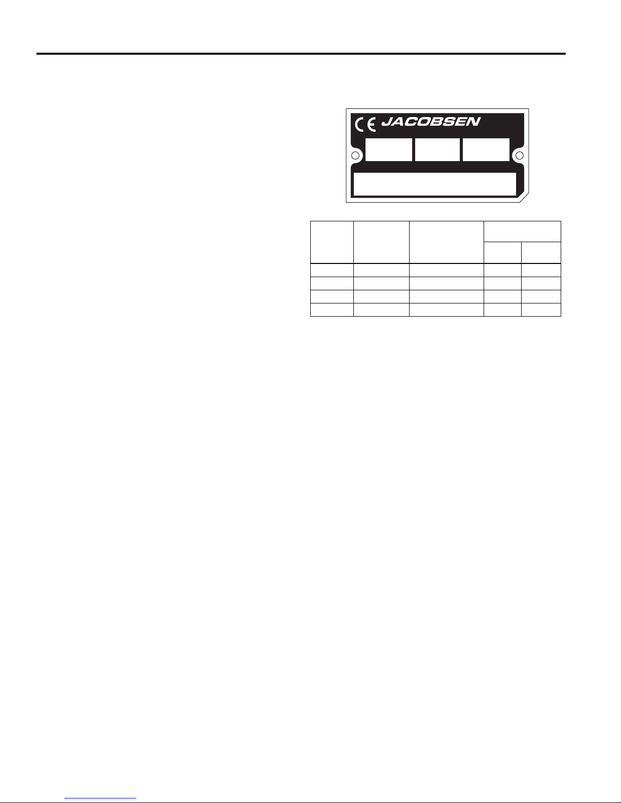
The serial plate is located on the to frame behind and to
the left of the traction pedal. Jacobsen recommends you
record these numbers below for easy reference.
These are the original instructions verified by
Jacobsen, A Textron Company.
© 2010, Jacobsen, A Textron Company/Textron Innovations Inc.
“All rights reserved, including the right to reproduce this material
1
or portions thereof in any form.”
Proposition 65 Warning
This product contains or emits
chemicals known to the State of
California to cause cancer and birth
defects or other reproductive harm.
LITHO IN U.S.A. 2-2014
Page 3

1DECALS
2SAFETY
2.1 Operating Safety . . . . . . . . . . . . . . . . . . . . . . 3
2.2 Important Safety Notes . . . . . . . . . . . . . . . . . 4
3 SPECIFICATIONS
3.1 Product Identification . . . . . . . . . . . . . . . . . . 5
3.2 Kubota D1305-E3B Engine . . . . . . . . . . . . . . 5
3.3 Kubota D1105-E4B Engine . . . . . . . . . . . . . . 5
3.4 Mower . . . . . . . . . . . . . . . . . . . . . . . . . . . . . . 5
3.5 Cutting Units . . . . . . . . . . . . . . . . . . . . . . . . . 6
3.6 Weights . . . . . . . . . . . . . . . . . . . . . . . . . . . . . 6
3.7 Accessories & Support Literature . . . . . . . . . 7
3.8 Declaration of Conformity . . . . . . . . . . . . . . . 8
4DECALS
4.1 Decals . . . . . . . . . . . . . . . . . . . . . . . . . . . . . 10
5 INITIAL INSPECTION
5.1 General . . . . . . . . . . . . . . . . . . . . . . . . . . . . 16
5.2 Initial Inspection . . . . . . . . . . . . . . . . . . . . . 16
6 CONTROLS
6.1 Pedal Controls . . . . . . . . . . . . . . . . . . . . . . . 17
6.2 Control Levers . . . . . . . . . . . . . . . . . . . . . . 18
6.3 Control Panel . . . . . . . . . . . . . . . . . . . . . . . 18
6.4 Operator Alerts . . . . . . . . . . . . . . . . . . . . . . 19
7 OPERATION
7.1 Daily Inspection . . . . . . . . . . . . . . . . . . . . . 20
7.2 Interlock System . . . . . . . . . . . . . . . . . . . . . 20
7.3 Operating Procedures . . . . . . . . . . . . . . . . . 21
7.4 Starting . . . . . . . . . . . . . . . . . . . . . . . . . . . . 22
7.5 Stopping / Parking . . . . . . . . . . . . . . . . . . . 22
7.6 To Drive / Transport . . . . . . . . . . . . . . . . . . 23
7.7 Hillside Operation . . . . . . . . . . . . . . . . . . . . 23
7.8 Mow Speed . . . . . . . . . . . . . . . . . . . . . . . . . 25
7.9 Mowing . . . . . . . . . . . . . . . . . . . . . . . . . . . . 25
7.10 After Operation . . . . . . . . . . . . . . . . . . . . . . 25
7.11 Towing / Trailering . . . . . . . . . . . . . . . . . . . 26
7.12 Daily Maintenance . . . . . . . . . . . . . . . . . . . 27
8 MAINTENANCE & LUBRICATION CHARTS
8.1 General . . . . . . . . . . . . . . . . . . . . . . . . . . . . 28
8.2 Lubrication Chart . . . . . . . . . . . . . . . . . . . . 28
8.3 Maintenance Charts . . . . . . . . . . . . . . . . . . 29
DECALS 1
9 MAINTENANCE
9.1 General . . . . . . . . . . . . . . . . . . . . . . . . . . . . 30
9.2 Engine . . . . . . . . . . . . . . . . . . . . . . . . . . . . 30
9.3 Engine Oil . . . . . . . . . . . . . . . . . . . . . . . . . . 30
9.4 Air Filter . . . . . . . . . . . . . . . . . . . . . . . . . . . 31
9.5 Fuel . . . . . . . . . . . . . . . . . . . . . . . . . . . . . . . 31
9.6 Fuel Manager . . . . . . . . . . . . . . . . . . . . . . . 32
9.7 Hand Primer Pump . . . . . . . . . . . . . . . . . . . 33
9.8 Bleeding Fuel System . . . . . . . . . . . . . . . . . 33
9.9 Battery . . . . . . . . . . . . . . . . . . . . . . . . . . . . 34
9.10 Jump Starting . . . . . . . . . . . . . . . . . . . . . . . 34
9.11 Charging Battery . . . . . . . . . . . . . . . . . . . . . 34
9.12 Hydraulic Hoses . . . . . . . . . . . . . . . . . . . . . 35
9.13 Hydraulic Oil and Filter . . . . . . . . . . . . . . . . 35
9.14 Electrical System . . . . . . . . . . . . . . . . . . . . 36
9.15 Muffler and Exhaust . . . . . . . . . . . . . . . . . . 36
9.16 Tires . . . . . . . . . . . . . . . . . . . . . . . . . . . . . . 36
9.17 Wheel Mounting Procedure . . . . . . . . . . . . 36
9.18 Care and Cleaning . . . . . . . . . . . . . . . . . . . 37
9.19 Radiator . . . . . . . . . . . . . . . . . . . . . . . . . . . 37
9.20 Storage . . . . . . . . . . . . . . . . . . . . . . . . . . . . 38
10 ADJUSTMENTS
10.1 General . . . . . . . . . . . . . . . . . . . . . . . . . . . . 39
10.2 Parking Brake . . . . . . . . . . . . . . . . . . . . . . . 39
10.3 Alternator Belt . . . . . . . . . . . . . . . . . . . . . . . 40
10.4 Rear Wheel Adjustments . . . . . . . . . . . . . . 40
10.5 Traction Pedal . . . . . . . . . . . . . . . . . . . . . . 41
10.6 Torque Specification . . . . . . . . . . . . . . . . . . 42
11 PROBLEM SOLVING
11.1 General . . . . . . . . . . . . . . . . . . . . . . . . . . . . 43
12 QUALITY OF CUT
12.1 Quality of Cut Troubleshooting . . . . . . . . . . 44
12.2 Washboarding . . . . . . . . . . . . . . . . . . . . . . 44
12.3 Step Cutting . . . . . . . . . . . . . . . . . . . . . . . . 45
12.4 Scalping. . . . . . . . . . . . . . . . . . . . . . . . . . . . 46
12.5 Stragglers . . . . . . . . . . . . . . . . . . . . . . . . . . 47
12.6 Streaks . . . . . . . . . . . . . . . . . . . . . . . . . . . . 48
12.7 Windrowing . . . . . . . . . . . . . . . . . . . . . . . . . 49
12.8 Mismatched Cutting Units . . . . . . . . . . . . . . 50
2
Page 4

2 SAFETY
!
2 SAFETY
2.1 OPERATING SAFETY ______________________________________________________
WARNING
EQUIPMENT OPERATED IMPROPERLY OR BY UNTRAINED PERSONNEL CAN BE DANGEROUS.
Familiarize yourself with the location and proper use of all controls. Inexperienced operators should receive instruction
from someone familiar with the equipment before being allowed to operate the machine.
1. Safety is dependent upon the awareness, concern,
and prudence of those who operate or service the
equipment. Never allow minors to operate any
equipment.
2. It is your responsibility to read this manual and all
publications associated with this equipment (Safety
& Operation Manual, Engine Manual, and
attachments/accessories instruction sheets). If the
operator cannot read English it is the owner’s
responsibility to explain the material contained in
this manual to them.
3. Learn the proper use of the machine, the location and
purpose of all the controls and gauges before you
operate the equipment. Working with unfamiliar
equipment can lead to accidents.
4. Never allow anyone to operate or service the machine
or its attachments without proper training and
instructions, or while under the influence of alcohol or
drugs.
5. Wear all the necessary protective clothing and
personal safety devices to protect your head, eyes,
ears, hands, and feet. Operate the machine only in
daylight or in good artificial light.
6. Evaluate the terrain to determine what accessories and
attachments are needed to properly and safely perform
the job. Only use accessories and attachments
approved by Jacobsen.
7. Stay alert for holes in the terrain and other hidden
hazards.
8. Inspect the area where the equipment will be used.
Pick up all the debris you can find before operating.
Beware of overhead obstructions (low tree limbs,
electrical wires, etc.) and also underground obstacles
(sprinklers, pipes, tree roots, etc.). Enter a new area
cautiously. Stay alert for hidden hazards.
9. Never direct discharge of material toward bystanders,
nor allow anyone near the machine while in operation.
The owner/operator can prevent and is responsible for
injuries inflicted to themselves, to bystanders, and
damage to property.
10. Do not carry passengers. Keep bystanders and pets a
safe distance away.
11. Never operate equipment that is not in perfect working
order or is without decals, guards, shields, discharge
deflectors, or other protective devices securely
fastened in place.
12. Never disconnect or bypass any switch.
13. Do not change the engine governor setting or
overspeed the engine.
14. Carbon monoxide in the exhaust fumes can be fatal
when inhaled. Never operate the engine without proper
ventilation or in an enclosed area.
15. Fuel is highly flammable, handle with care.
16. Keep the engine clean. Allow the engine to cool before
storing and always remove the ignition key.
17. Disengage all drives and engage parking brake before
starting the engine (motor). Start the engine only when
sitting in operator’s seat, never while standing beside
the unit.
18. Equipment must comply with the latest federal, state,
and local requirements when driven or transported on
public roads. Watch out for traffic when crossing or
operating on or near roads.
19. Local regulations may restrict the age of the operator.
20. Operate the machine up and down the face of slopes
(vertically), not across the face (horizontally).
21. To prevent tipping or loss of control, do not start or
stop suddenly on slopes. Reduce speed when making
sharp turns. Use caution when changing directions.
22. Always use the seat belt when operating mowers
equipped with a Roll Over Protective Structure
(ROPS).
Never use a seat belt when operating mowers without a
ROPS.
Accessory operator protective structures will
continue to be offered for all equipment currently
covered. This allows for the outfitting of any
machines without previous ROPS installations or
replacement of damaged structures.
23. Keep legs, arms, and body inside the seating
compartment while the vehicle is in motion.
24. Disconnect batteries before performing any welding on
this mower.
This machine is to be operated and maintained as specified in this manual and is intended for the professional
maintenance of specialized turf grasses. It is not intended for use on rough terrain or long grasses.
3
Page 5

SAFETY 2
!
!
2.2 IMPORTANT SAFETY NOTES________________________________________________
This safety alert symbol is used to alert you to potential hazards.
DANGER - Indicates an imminently hazardous situation which, if not avoided, WILL result in death or serious injury.
WARNING - Indicates a potentially hazardous situation which, if not avoided, COULD result in death or serious
injury.
CAUTION - Indicates a potentially hazardous situation which, if not avoided, MAY result in minor or moderate injury
and property damage. It may also be used to alert against unsafe practices.
NOTICE - Indicates a potentially hazardous situation which, if not avoided, MAY result in property damage. It may
also be used to alert against unsafe practices.
For pictorial clarity, some illustrations in this manual may show shields, guards, or plates, open or removed. Under no
circumstances should this equipment be operated without these devices securely fastened in place.
WARNING
The Interlock System on this mower prevents the mower from starting unless
the parking brake is engaged, PTO switch is OFF, and traction pedal is in
Neutral. The system will stop the engine if the operator leaves the seat
without the parking brake engaged, traction pedal in Neutral, or setting the
PTO switch OFF.
NEVER operate mower unless the Interlock System is working.
WARNING
1. Before leaving the operator’s position for any reason:
a. Return traction pedal to Neutral.
b. Disengage all drives.
c. Lower all implements to the ground.
d. Engage parking brake.
e. Stop engine and remove the ignition key.
2. Keep hands, feet, and clothing away from moving parts. Wait for all
movement to stop before you clean, adjust, or service the machine.
3. Keep the area of operation clear of all bystanders and pets.
4. Never carry passengers, unless a seat is provided for them.
5. Never operate mowing equipment without the discharge deflector
securely fastened in place.
By following all instructions in this manual, you will prolong the life of your machine and maintain its maximum
efficiency. Adjustments and maintenance should always be performed by a qualified technician.
If additional information or service is needed, contact your Authorized Jacobsen Dealer who is kept informed of the
latest methods to service this equipment and can provide prompt and efficient service.
4
Page 6
3 SPECIFICATIONS
653 21.7 XXXX
69168001651
3 SPECIFICATIONS
3.1 PRODUCT IDENTIFICATION_________________________________________________
69168.............................. Turfcat T628D 2WD with ROPS
®
69169.............................. Turfcat T628D 4WD with ROPS
69175.............................. Turfcat T628D 2WD with ROPS
69176.............................. Turfcat T628D 4WD with ROPS
69184.............................. Turfcat T628D 2WD with ROPS
69185.............................. Turfcat T628D 4WD with ROPS
Serial Number ................An identification plate, like the one
shown, listing the serial number, is
attached to frame behind and to
the left of the traction pedal.
Always provide the serial number of the unit when ordering
replacement parts or requesting service information.
PRODUCT OF U.S.A.
kg kW
EEC
Product
Sound
Power
69168 105 dB(A) 93 dB(A) 1.991 0.066
69169 105 dB(A) 93 dB(A) 1.991 0.066
69175 105 dB(A) 93 dB(A) 1.991 0.066
69176 105 dB(A) 93 dB(A) 1.991 0.066
A Textron Company
Sound Power
Level
Operator Ear
11524 WILMAR BLVD,
CHARLOTTE, NC 28273
1-800-848-1636 (US)
Vibration M/S
Arms Body
2
3.2 KUBOTA D1305-E3B ENGINE________________________________________________
Turfcat Models 69168, 69169, 69175 and 69176
Make ............................... Kubota
Model .............................. D1305-E3B
Horsepower..................... 29.1 hp (21.7 kW) @3000 rpm
Note: Actual sustained horsepower will likely be lower
than listed in specifications due to operating limitations
and environmental factors.
Displacement .................. 76.95 cu. In. (1261 cc)
Torque ............................. 59.1 ft lbs. (80.1 Nm) @ 2000 rpm
Fuel:
Type .......................... No. 2 Low or Ultra Low Sulfur
Diesel
Rating ....................... Cetane Rating-45
Capacity.................... 9 U.S. Gal. (34 liters)
High Idle - rpm ................ 3220 no load
Low Idle - rpm................. 1750 no load
Lubrication:
Capacity.................... 6 qt (5.7 liters)
Type .......................... SAE 10W30
API Classification ..... CD,CE
Air Filter .......................... Dry type with service indicator
Alternator ........................ 40 amp
Cooling System .............. Liquid Cooled
3.3 KUBOTA D1105-E4B ENGINE________________________________________________
Turfcat Models 69184 and 69185
Make ............................... Kubota
Model .............................. D1105-E4B
Horsepower..................... 24.8 hp (18.5 kW) @3000 rpm
Note: Actual sustained horsepower will likely be lower
than listed in specifications due to operating limitations
and environmental factors.
Displacement .................. 68.5 cu. In. (1123 cc)
Torque ............................. 52.7 ft lbs. (71.5 Nm) @ 2200 rpm
Fuel:
Type .......................... No. 2 Low or Ultra Low Sulfur
Rating ....................... Cetane Rating-45
Capacity.................... 9 U.S. Gal. (34 liters)
High Idle - rpm ................ 3150 no load
Low Idle - rpm................. 1750 no load
Lubrication:
Capacity.................... 5.4 qt (5.1 liters)
Type .......................... SAE 10W30
API Classification ..... CJ
Air Filter .......................... Dry type with service indicator
Alternator ........................ 40 amp
Cooling System .............. Liquid Cooled
Diesel
3.4 MOWER _________________________________________________________________
5
Page 7

SPECIFICATIONS 3
Tires
Front.......................... 23 x 10.5-12 4 Ply
Rear .......................... 18 x 8.5-9 4 Ply
Pressure:......................... 14 psi (1 BAR)
Battery:
Type .......................... 12 Volt Lead/Acid
Group ........................45 GMF
Parking Brake..................Mechanical front wheel drum
Speed:
Mow .......................... 0 - 6 mph (9.6 kph)
Transport................... 0 - 10 mph (16.1 kph)
Reverse..................... 0 - 3 mph (4.8 kph)
Hydraulic System:
Capacity.......................... 6.8 U.S. gal. (25.7 liters) System
Fluid Type ....................... 10W30
Return Filter.................... Full Flow 10 micron
Steering ......................... Hydrostatic Power Steering
Mower Lift ....................... Hand operated, lever controlled
hydraulic lift system
3.5 CUTTING UNITS ___________________________________________________________
Caster wheels ................. Two 11 x 4.5 pneumatic, tubeless
4 ply.
Weight Transfer ...............Spring transfer 180 lbs. (82 kg)
from cutting deck to mower
Blades/Decks ..................Fine-cut flail, rear discharge, side
discharge or mulcher
Cutting Width ..................60 in. (1524 mm), 63 in. (1600
mm), or 72 in. (1829 mm)
Cutting Capacity @ 5.5 mph (9 kph)
60 in. (1524 mm)....... 3.3 acres (1.3 ha)/hr
63 in. (1600 mm)....... 3.5 acres (1.4 ha)/hr
72 in. (1829 mm)....... 4 acres (1.6 ha)/hr
Height-of-cut ................... 1 to 4-3/4 in. (25 to 121 mm) in 1/4
in. (6 mm) increments
3.6 WEIGHTS ________________________________________________________________
Dimensions: Inches (mm)
Length ............................................................. 88 (2235)
Height - Top of ROPS...................................... 82 (2083)
Height (Cab installed) .................................. 83.5 (2121)
Wheel Base..................................................... 52 (1320)
Width (Without Mower).................................... 52 (1320)
Weights: Lbs. (kg)
Without Deck
69168 and 69175 ........................................ 1440 (653)
69169 and 69176 ........................................ 1490 (676)
69168 and 69175 with Cab ......................... 2728 (1237)
69169 and 69176 with Cab ......................... 2778 (1260)
6
Page 8

3 SPECIFICATIONS
!
3.7 ACCESSORIES & SUPPORT LITERATURE ____________________________________
Contact your area Jacobsen Dealer for a complete listing of accessories and attachments.
CAUTION
Use of other than Jacobsen authorized parts and accessories may cause personal injury or damage to the
equipment and will void the warranty.
Accessories
Air Blow Gun........................................................... JAC5098
Orange Touch-up Paint (12 oz. spray) .....................4184140
Canopy.........................................................................68127
Care Free Deck Tires...............................................2811454
Tie down brackets......................................................970114
Turn Assist/Steering Brakes.......................................970211
Differential Lock (2WD Only) .....................................970116
Exhaust Spark Arrestor..............................................148098
Leaf Mulcher ..............................................................970017
Cab ..........................................................................4265610
Sun Shades .......................................................................
Rotary Brush/Front Blades ...............................................
Contact: Sunguard
16930 South Shawnee Heights
Overbrook, KS 66524
Phone 800-899-2406
Fax (800) 899-2406
Debris Blower ....................................................................
Counterweight (Standard on 2WD Units) ................ 2192304
Cutting Units
60 in. (1524 mm) Hydraulic Rear Discharge Deck .... 956023
63 in. (1600 mm) Hydraulic Side Discharge Deck..... 956314
72 in. (1829 mm) Hydraulic Rear Discharge Deck .... 957234
72 in. (1829 mm) Hydraulic Side Discharge Deck..... 957233
60 in. (1524 mm) Hydraulic Flail Mower .................... 956025
Support Literature
Safety & Operation Manual......................................4201281
Parts & Maintenance Manual ..................................4304419
Service Manual........................................................ 4171722
DVD, Operator Training............................................ 4191628
Contact: M-B Companies, Inc.
1200 Park Street, Box 148
Chilton, WI 53014
Phone: (888) 558-5801
Fax: (920) 898-4588
Contact: Buffalo Turbine Agricultural Equipment
180 Zoar Road
Springville, NY 14141
Phone: (716) 592-2700
Fax: (716) 592-2460
7
Page 9

SPECIFICATIONS 3
3.8 DECLARATION OF CONFORMITY ____________________________________________
DECLARATION OF CONFORMITY ▪ ДЕКЛАРАЦИЯ ЗА СЪОТВЕТСТВИЕ ▪ PROHLÁŠENÍ O SHODĚ ▪
OVERENSSTEMMELSESERKLÆRING ▪ CONFORMITEITSVERKLARING ▪ VASTAVUSDEKLARATSIOON ▪
VAATIMUSTENMUKAISUUSVAKUUTUS ▪ DECLARATION DE CONFORMITE ▪ KONFORMITÄTSERKLÄRUNG ▪
∆ΗΛΩΣΗ ΣΥΜΜΟΡΦΩΣΗΣ ▪ MEGFELELŐSÉGI NYILATKOZAT ▪ DICHIARAZIONE DI CONFORMITÀ ▪ ATBILSTĪBAS
DEKLARĀCIJA ▪ ATITIKTIES DEKLARACIJA ▪ DIKJARAZZJONI TAL-KONFORMITÀ ▪ DEKLARACJA ZGODNOŚCI ▪
DECLARAÇÃO DE CONFORMIDADE ▪ DECLARAŢIE DE CONFORMITATE ▪ VYHLÁSENIE O ZHODE ▪ IZJAVA O
SKLADNOSTI ▪ DECLARACIÓN DE CONFORMIDAD ▪ DEKLARATION OM ÖVERENSSTÄMMELSE
Business name and full address of the manufacturer ▪ Търговско име и пълен адрес на производителя ▪ Obchodní jméno a plná adresa výrobce ▪
Producentens firmanavn og fulde adresse ▪ Bedrijfsnaam en volledig adres van de fabrikant ▪ Tootja ärinimi ja täielik aadress ▪
Valmistajan toiminimi ja täydellinen osoite ▪ Nom commercial et adresse complète du fabricant ▪ Firmenname und vollständige Adresse des Herstellers ▪
Επωνυμία και ταχυδρομική διεύθυνση κατασκευαστή ▪ A gyártó üzleti neve és teljes címe ▪ Ragione sociale e indirizzo completo del fabbricante ▪
Uzņēmuma nosaukums un pilna ražotāja adrese ▪ Verslo pavadinimas ir pilnas gamintojo adresas ▪ Isem kummerċjali u indirizz sħiħ tal-fabbrikant ▪
Nazwa firmy i pełny adres producenta ▪ Nome da empresa e endereço completo do fabricante ▪ Denumirea comercială şi adresa completă a
producătorului ▪ Obchodný názov a úplná adresa výrobcu ▪ Naziv podjetja in polni naslov proizvajalca ▪ Nombre de la empresa y dirección completa del
fabricante ▪ Tillverkarens företagsnamn och kompletta adress
Product Code ▪ Код на
▪ Termékkód ▪ Codice prodotto ▪ Produkta kods ▪ Produkto kodas ▪ Kodiċi tal-Prodott ▪ Kod produktu ▪ Código do Produto ▪ Cod produs ▪ Kód výrobku ▪
Oznaka proizvoda ▪ Código de producto ▪ Produktkod
Machine Name ▪ Наименование на машината ▪ Název stroje ▪ Maskinnavn ▪ Machinenaam ▪ Masina nimi ▪ Laitteen nimi ▪ Nom de la machine ▪
Maschinenbezeichnung ▪ Ονομασία μηχανήματος ▪ Gépnév ▪ Denominazione della macchina ▪ Iekārtas nosaukums ▪ Mašinos pavadinimas ▪ Isem talMagna ▪ Nazwa urządzenia ▪ Nome da Máquina
Designation ▪ Предназначение ▪ Označení ▪ Betegnelse ▪ Benaming ▪ Nimetus ▪ Tyyppimerkintä ▪ Pažymėjimas ▪ Bezeichnung ▪ Χαρακτηρισμός ▪
Megnevezés ▪ Funzione ▪ Apzīmējums ▪ Lithuanian ▪ Denominazzjoni ▪ Oznaczenie ▪ Designação ▪ Specificaţie ▪ Označenie ▪ Namen stroja ▪ Descripción
▪ Beteckning
Serial Number ▪ Сериен номер ▪ Sériové číslo ▪ Serienummer ▪ Serienummer ▪ Seerianumber ▪ Valmistusnumero ▪ Numéro de série ▪ Seriennummer ▪
Σειριακός αριθμός
serie ▪ Sériové číslo ▪ Serijska številka ▪ Número de serie ▪ Serienummer
Engine ▪ Двигател ▪ Motor ▪ Motor ▪ Motor ▪ Mootor ▪ Moottori ▪ Moteur ▪ Motor ▪ Μηχανή ▪ Modulnév ▪ Motore ▪ Dzinējs ▪ Variklis ▪ Saħħa Netta Installata ▪
Silnik ▪ Motor ▪ Motor ▪ Motor ▪ Motor ▪ Motor ▪ Motor
Net Installed Power ▪ Нетна инсталирана мощност ▪
netovõimsus ▪ Asennettu nettoteho ▪ Puissance nominale nette ▪ Installierte Nettoleistung ▪ Καθαρή εγκατεστημένη ισχύς ▪ Nettó beépített teljesítmény ▪
Potenza netta installata ▪ Paredzētā tīkla jauda ▪ Grynoji galia ▪ Wisa’ tal-Qtugħ ▪ Moc zainstalowana netto ▪ Potência instalada ▪ Puterea instalată netă ▪
Čistý inštalovaný výkon ▪ Neto vgrajena moč ▪ Potencia instalada neta ▪ Nettoeffekt
Cutting Width ▪ Широчина на рязане ▪ Šířka řezu ▪ Skærebredde ▪ Maaibreedte ▪ Lõikelaius ▪ Leikkuuleveys ▪ Largeur de coupe ▪ Schnittbreite ▪
Μήκος μισινέζας ▪ Vágási szélesség
Largura de Corte ▪ Lăţimea de tăiere ▪ Šírka záberu ▪ Širina reza ▪ Anchura de corte ▪ Klippbredd
Conforms to Directives ▪ В съответствие с директивите ▪ Splňuje podmínky směrnic ▪ Er i overensstemmelse med direktiver ▪ Voldoet aan de richtlijnen ▪
Vastab direktiividele ▪ Direktiivien mukainen ▪ Conforme aux directives ▪ Entspricht Richtlinien ▪ Ακολουθήστε πιστά τις Οδηγίες ▪ Megfelel az irányelveknek
▪ Conforme alle Direttive ▪ Atbilst direktīvām ▪ Atitinka direktyvų reikalavimus ▪ Valutazzjoni tal-Konformità ▪ Dyrektywy związane ▪ Cumpre as Directivas ▪
Respectă Directivele ▪ Je v súlade so smernicami
Conformity Assessment ▪ Оценка за съответствие ▪ Hodnocení plnění podmínek ▪ Overensstemmelsesvurdering ▪ Conformiteitsbeoordeling ▪
Vastavushindamine ▪ Vaatimustenmukaisuuden arviointi ▪ Evaluation de conformité ▪ Konformitätsbeurteilung ▪ ∆ιαπίστωση Συμμόρφωσης ▪
Megfelelőség-értékelés ▪ Valutazione della conformità ▪ Atbilstības novērtējums ▪ Atitikties įvertinimas ▪ Livell tal-Qawwa tal-Ħoss Imkejjel ▪ Ocena
zgodności ▪ Avaliação de Conformidade ▪ Evaluarea conformităţii ▪ Vyhodnotenie zhodnosti ▪ Ocena skladnosti ▪ Evaluación de conformidad ▪
Bedömning av överensstämmelse
Measured Sound Power Level ▪ Измерено ниво на звукова мощност ▪ Naměřený akustický výkon
Mõõdetud helivõimsuse tase ▪ Mitattu äänitehotaso ▪ Niveau de puissance sonore mesuré ▪ Gemessener Schalldruckpegel ▪
Σταθ μισμένο επίπεδο ηχητικής ισχύος ▪ Mért hangteljesítményszint ▪ Livello di potenza sonora misurato ▪ Izmērītais skaņas jaudas līmenis ▪
Išmatuotas garso stiprumo lygis ▪ Livell tal-Qawwa tal-Ħoss Iggarantit ▪ Moc akustyczna mierzona ▪ Nível sonoro medido ▪ Nivelul măsurat al puterii
acustice ▪ Nameraná hladina akustického výkonu ▪ Izmerjena raven zvočne moči ▪ Nivel de potencia sonora medido ▪ Uppmätt ljudeffektsnivå
Guaranteed Sound Power Level ▪ Гарантирано ниво на звукова мощност ▪ Garantovaný akustický výkon ▪ Garanteret lydstyrkeniveau ▪
Gegarandeerd geluidsniveau ▪ Garanteeritud helivõimsuse tase ▪ Taattu äänitehotaso ▪ Niveau de puissance sonore garanti ▪ Garantierter
Schalldruckpegel ▪ Εγγυημένο επίπεδο
jaudas līmenis ▪ Garantuotas garso stiprumo lygis ▪ Livell tal-Qawwa tal-Ħoss Iggarantit ▪ Moc akustyczna gwarantowana ▪ Nível sonoro farantido ▪
Nivelul garantat al puterii acustice ▪ Garantovaná hladina akustického výkonu ▪ Zajamčena raven zvočne moči ▪ Nivel de potencia sonora garantizado ▪
Garanterad ljudeffektsnivå
Conformity Assessment Procedure (Noise) ▪ Оценка за съответствие на процедурата (Шум) ▪ Postup hodnocení plnění podmínek (hluk) ▪
Procedure for overensstemmelsesvurdering (Støj) ▪ Procedure van de conformiteitsbeoordeling (geluid) ▪ Vastavushindamismenetlus (müra) ▪
Vaatimustenmukaisuuden arviointimenettely (Melu) ▪ Procédure d’évaluation de conformité (bruit) ▪ Konformitätsbeurteilungsverfahren (Geräusch) ▪
∆ιαδικασία Αξιολόγησης Συμμόρφωσης (Θόρυβος) ▪ Megfelelőség-értékelési eljárás (Zaj) ▪ Procedura di valutazione della conformità (rumore) ▪
Atbilstības novē
Procedura oceny zgodności (poziom hałasu) ▪ Processo de avaliação de conformidade (nível sonoro) Procedura de evaluare a conformităţii (zgomot) ▪
Postup vyhodnocovania zhodnosti (hluk) ▪ Postopek za ugotavljanje skladnosti (hrup) ▪ Procedimiento de evaluación de conformidad (ruido) ▪
Procedur för bedömning av överensstämmelse (buller)
продукта ▪ Kód výrobku ▪ Produktkode ▪ Productcode ▪ Toote kood ▪ Tuotekoodi ▪ Code produit ▪ Produktcode ▪ Κωδικός προϊόντος
▪ Numele echipamentului ▪ Názov stroja ▪ Naziv stroja ▪ Nombre de la máquina ▪ Maskinens namn
▪ Sorozatszám ▪ Numero di serie ▪ Sērijas numurs ▪ Serijos numeris ▪ Numru Serjali ▪ Numer seryjny ▪ Número de Série ▪ Număr de
Čistý instalovaný výkon ▪ Installeret nettoeffekt ▪ Netto geïnstalleerd vermogen ▪ Installeeritud
▪ Larghezza di taglio ▪ Griešanas platums ▪ Pjovimo plotis ▪ Tikkonforma mad-Direttivi ▪ Szerokość cięcia ▪
▪ Skladnost z direktivami ▪ Cumple con las Directivas ▪ Uppfyller direktiv
▪ Målte lydstyrkeniveau ▪ Gemeten geluidsniveau ▪
ηχητικής ισχύος ▪ Szavatolt hangteljesítményszint ▪ Livello di potenza sonora garantito ▪ Garantētais skaņas
rtējuma procedūra (troksnis) ▪ Atitikties įvertinimo procedūra (garsas) ▪ Proċedura tal-Valutazzjoni tal-Konformità (Ħoss) ▪
Jacobsen, A Textron Company
11524 Wilmar Blvd.
Charlotte, NC 28273, USA
69168 and 69175
69169 and 69176
69184
69185
Turfcat 628D 2WD
Turfcat 628D 4WD
Turfcat 628D 2WD
Turfcat 628D 4WD
Lawnmower, Article 12, Item 32
6916801651-6916802500
6916801651-6916802500
6917501651-6917502500
6917601651-6917602500
6918401651-6918402500
6918501651-6918502500
Kubota D1305-E3B Diesel
Kubota D1305-E3B Diesel
Kubota D1305-E3B Diesel
Kubota D1305-E3B Diesel
Kubota D1105-E4B Diesel
Kubota D1105-E4B Diesel
21,7 kW @ 3000 RPM
21,7 kW @ 3000 RPM
18,5 kW @ 3000 RPM
18,5 kW @ 3000 RPM
1,52 m to 1,83 m
2004/108/EC
2006/42/EC
2000/14/EC, 2005/88/EC
2006/66/EC
2006/42/EC Annex VIII
104 dB(A) LWA
105 dB(A) LWA
2000/14/EC Annex VI, Part 1
8
Page 10
3 SPECIFICATIONS
UK Notified Body for 2000/14/EC ▪ Нотифициран орган в Обединеното кралство за 2000/14/ЕО ▪ Úřad certifikovaný podle směrnice č. 2000/14/EC ▪
Det britiske bemyndigede organ for 2001/14/EF ▪ Engels adviesorgaan voor 2000/14/EG ▪ Ühendkuningriigi teavitatud asutus direktiivi 2000/14/EÜ
mõistes ▪ Direktiivin 2000/14/EY mukainen ilmoitettu tarkastuslaitos Isossa-Britanniassa ▪ Organisme notifié concernant la directive 2000/14/CE ▪
Britische benannte Stelle für 2000/14/EG ▪ Κοινοποιημένος Οργανισμός Ηνωμένου Βασιλείου για 2000/14/ΕΚ ▪
2000/14/EK – egyesült királyságbeli bejelentett szervezet ▪ Organismo Notificato in GB per 2000/14/CE ▪ 2000/14/EK AK reģistrētā organizācija ▪
JK notifikuotosios įstaigos 2000/14/EC ▪ Korp Notifikat tar-Renju Unit għal 2000/14/KE ▪ Dopuszczona jednostka badawcza w Wielkiej Brytanii wg 2000/
14/WE ▪ Entidade notificada no Reino Unido para 2000/14/CE ▪ Organism notificat în Marea Britanie pentru 2000/14/CE ▪
Notifikovaný orgán Spojeného kráľovstva pre smernicu 2000/14/ES ▪ Britanski priglašeni organ za 2000/14/ES ▪
Cuerpo notificado en el Reino Unido para 2000/14/CE ▪ Anmält organ för 2000/14/EG i Storbritannien
Operator Ear Noise Level ▪ Оператор на нивото на доловим от ухото шум ▪ Hladina hluku v oblasti uší operátora ▪ Støjniveau i førers ørehøjde ▪
Geluidsniveau oor bestuurder ▪ Müratase operaatori kõrvas ▪ Melutaso käyttäjän korvan kohdalla ▪ Niveau de bruit à hauteur des oreilles de l’opérateur ▪
Schallpegel am Bedienerohr ▪ Επίπεδο θορύβου σε λειτουργία ▪ A kezelő fülénél mért zajszint ▪ Livello di potenza sonora all’orecchio dell’operatore ▪
Trokšņa līmenis pie operatora auss ▪ Dirbančiojo su mašina patiriamo triukšmo lygis ▪ Livell tal-Ħoss fil-Widna tal-Operatur ▪
Dopuszczalny poziom hałasu dla operatora ▪ Nível sonoro nos ouvidos do operador ▪ Nivelul zgomotului la urechea operatorului ▪
Hladina hluku pôsobiaca na sluch operátora ▪ Raven hrupa pri ušesu upravljavca ▪ Nivel sonoro en el oído del operador ▪ Ljudnivå vid förarens öra
Harmonised standards used ▪ Използвани хармонизирани стандарти ▪ Použité harmonizované normy ▪ Brugte harmoniserede standarder ▪
Gebruikte geharmoniseerde standaards
Angewandte harmonisierte Normen ▪ Εναρμονισμένα πρότυπα που χρησιμοποιήθηκαν ▪ Harmonizált szabványok ▪ Standard armonizzati applicati ▪
Izmantotie saskaņotie standarti ▪ Panaudoti suderinti standartai ▪ Standards armonizzati użati ▪ Normy spójne powiązane ▪ Normas harmonizadas usadas
▪ Standardele armonizate utilizate ▪ Použité harmonizované normy ▪ Uporabljeni usklajeni standardi ▪ Estándares armonizados utilizados ▪
Harmoniserade standarder som används
Technical standards and specifications used ▪ Използвани технически стандарти и спецификации ▪ Použité technické normy a specifikace ▪
Brugte tekniske standarder og specifikationer ▪ Gebruikte technische standaards en specificaties ▪ Kasutatud tehnilised standardid ja spetsifikatsioonid ▪
Käytetyt tekniset standardit ja eritelmät ▪ Spécifications et normes techniques utilisées ▪ Angewandte technische Normen und Spezifikationen ▪
Τεχνι κ ά πρότυπα και προδιαγραφές που χρησιμοποιήθηκαν ▪ Műszaki szabványok és specifikációk
Izmantotie tehniskie standarti un specifikācijas ▪ Panaudoti techniniai standartai ir techninė informacija ▪ Standards u speċifikazzjonijiet tekniċi użati ▪
Normy i specyfikacje techniczne powiązane ▪ Normas técnicas e especificações usadas ▪ Standardele tehnice şi specificaţiile utilizate ▪
Použité technické normy a špecifikácie ▪ Uporabljeni tehnični standardi in specifikacije ▪ Estándares y especificaciones técnicas utilizadas ▪
Tekniska standarder och specifikationer som används
The place and date of the declaration ▪ Място и дата на декларацията ▪ Místo a datum prohlášení ▪ Sted og dato for erklæringen ▪
Plaats en datum van de verklaring ▪ Deklaratsiooni väljastamise koht ja kuupäev ▪ Vakuutuksen paikka ja päivämäärä ▪ Lieu et date de la déclaration ▪
Ort und Datum der Erklärung ▪ Τόπ ο ς και ημερομηνία δήλωσης ▪ A nyilatkozat kelte (hely és idő) ▪ Luogo e data della dichiarazione ▪
Deklarācijas vieta un datums ▪ Deklaracijos vieta ir data ▪ Il-post u d-data tad-dikjarazzjoni ▪
declaração ▪ Locul şi data declaraţiei ▪ Miesto a dátum vyhlásenia ▪ Kraj in datum izjave ▪ Lugar y fecha de la declaración ▪ Plats och datum för
deklarationen
Signature of the person empowered to draw up the declaration on behalf of the manufacturer, holds the technical documentation and is authorised to
compile the technical file, and who is established in the Community.
Подпис на човека, упълномощен да състави декларацията от името на производителя, който поддържащ техническата документация и е
оторизиран да изготви техническия файл и е регистриран в общността.
Podpis osoby oprávněné sestavit prohlášení jménem výrobce, držet technickou dokumentaci a osoby oprávněné sestavit technické soubory a založené v
rámci Evropského společenství.
Underskrift af personen, der har fuldmagt til at udarbejde erklæringen på vegne af producenten, der er indehaver af dokumentationen og er bemyndiget til
at udarbejde den tekniske journal, og som er baseret i nærområdet.
Handtekening van de persoon die bevoegd is de verklaring namens de fabrikant te tekenen, de technische documentatie bewaart en bevoegd is om het
technische bestand samen te stellen, en die is gevestigd in het Woongebied.
Ühenduse registrisse kantud isiku allkiri, kes on volitatud tootja nimel deklaratsiooni koostama, kes omab tehnilist dokumentatsiooni ja kellel on õigus
koostada tehniline toimik.
Sen henkilön allekirjoitus, jolla on valmistajan valtuutus vakuutuksen laadintaan, jolla on hallussaan tekniset asiakirjat, joka on valtuutettu laatimaan
tekniset asiakirjat ja joka on sijoittautunut yhteisöön.
Signature de la personne habilitée à rédiger la déclaration au nom du fabricant, à détenir la documentation technique, à compiler les fichiers techniques et
qui est implantée dans la Communauté.
Unterschrift der Person, die berechtigt ist, die Erklärung im Namen des Herstellers abzugeben, die die technischen Unterlagen aufbewahrt und berechtigt
ist, die technischen Unterlagen zusammenzustellen, und die in der Gemeinschaft niedergelassen ist.
Υπογραφή ατόμου εξουσιοδοτημένου για την σύνταξη της δήλωσης εκ μέρους του κατασκευαστή, ο οποίος κατέχει την τεχνική έκθεση και έχει την
εξουσιοδότηση να ταξινομήσει τον τεχνικό φάκελο και ο οποίος είναι διορισμένος στην Κοινότητα.
A gyártó nevében meghatalmazott személy, akinek jogában áll módosítania a nyilatkozatot, a műszaki dokumentációt őrzi, engedéllyel rendelkezik a
műszaki fájl összeállításához, és aki a közösségben letelepedett személy.
Firma della persona autorizzata a redigere la dichiarazione a nome del fabbricante, in possesso Della documentazione tecnica ed autorizzata a costituire
il fascicolo tecnico, che deve essere stabilita nella Comunità.
Tās personas paraksts, kura ir pilnvarota deklarācijas sastādīšanai ražotāja vārdā, kurai ir tehniskā dokumentācija, kura ir pilnvarota sagatavot tehnisko
ģistru un kura ir apstiprināta Kopienā.
re
Asmuo, kuris yra gana žinomas, kuriam gamintojas suteikė įgaliojimus sudaryti šią deklaraciją, ir kuris ją pasirašė, turi visą techninę informaciją ir yra
įgaliotas sudaryti techninės informacijos dokumentą.
Il-firma tal-persuna awtorizzata li tfassal id-dikjarazzjoni f’isem il-fabbrikant, għandha d-dokumentazzjoni teknika u hija awtorizzata li tikkompila l-fajl
tekniku u li hija stabbilita fil-Komunità.
Podpis osoby upoważnionej do sporządzenia deklaracji w imieniu producenta, przechowującej dokumentację techniczną, upoważnioną do stworzenia
dokumentacji technicznej oraz wyznaczonej ds. wspólnotowych.
Assinatura da pessoa com poderes para emitir a declaração em nome do fabricante, que possui a documentação técnica, que está autorizada a compilar
o processo técnico e que está estabelecida na Comunidade.
Semnătura persoanei împuternicite să elaboreze declaraţia în numele producătorului, care deţine documentaţia tehnică, este autorizată să compileze
dosarul tehnic şi este stabilită în Comunitate.
Podpis osoby poverenej vystavením vyhlásenia v mene výrobcu, ktorá má technickú dokumentáciu a je oprávnená spracovať technické podklady a ktorá
je umiestnená v Spoločenstve.
Podpis osebe, pooblaščene za izdelavo izjave v imenu proizvajalca, ki ima tehnično dokumentacijo in lahko sestavlja spis tehnične dokumentacije, ter ima
sedež v Skupnosti.
Firma de la persona responsable de la declaración en nombre del fabricante, que posee la documentación técnica y está autorizada para recopilar el
archivo técnico y que está establecido en la Comunidad.
Undertecknas av den som bemyndigad att upprätta deklarationen å tillverkarens vägnar, innehar den tekniska dokumentationen och är bemyndigad att
sammanställa den tekniska informationen och som är etablerad i gemenskapen.
Certificate Number ▪ Номер на сертификат ▪ Číslo osvědčení ▪ Certifikatnummer ▪ Certificaatnummer ▪ Sertifikaadi number ▪ Hyväksyntänumero ▪
Numéro de certificat ▪ Bescheinigungsnummer ▪ Αριθμός Πιστοποιητικού ▪ Hitelesítési szám ▪ Numero del certificato ▪ Sertifikāta numurs ▪
Sertifikato numeris ▪ Numru taċ-Ċertifikat ▪ Numer certyfikatu ▪ Número do Certificado ▪ Număr certificat ▪ Číslo osvedčenia ▪ Številka certifikata ▪
Número de certificado ▪ Certifikatsnummer
▪ Kasutatud ühtlustatud standardid ▪ Käytetyt yhdenmukaistetut standardit ▪ Normes harmonisées utilisées ▪
▪ Standard tecnici e specifiche applicati ▪
Miejsce i data wystawienia deklaracji ▪ Local e data da
Sound Research Laboratories Limited
93 dB(a) Leq (2006/42/EC)
BS EN ISO 20643
BS EN ISO 5349-1
BS EN ISO 5349-2
BS EN 836
B71.4
ISO 2631-1
OSHA 1928.51
Jacobsen, A Textron Company
11524 Wilmar Blvd.
Charlotte, NC 28273, USA
February 5, 2014
4201281 Rev B
Number: 1088
Holbrook House, Little Waldingfield
Sudbury, Suffolk CO10 0TH
2006/42/EC Annex II 1.A.2
Tim Lansdell
Technical Director
Ransomes Jacobsen Limited
West Road, Ransomes Europark,
Ipswich, IP3 9TT, England
2006/42/EC Annex II 1.A.10
Vasant Godhalekar
VP of Engineering
Jacobsen, A Textron Company
11524 Wilmar Blvd,
Charlotte, NC 28273, USA
9
Page 11

DECALS 4
4181865
2000739
• Read operator's manual. Do not allow untrained
operators to use machine.
• Keep shields in place and hardware securely
fastened.
• Keep hands, feet, and clothing away from moving
parts.
• Before you clean, adjust, or repair this equipment,
disengage all drives, engage parking brake, and stop
engine.
• Never carry passengers.
• Keep bystanders away.
• Do not use on slopes greater than 15°.
Rotating Fan.
Keep hands clear.
Stop engine before servicing.
Read and understand Safety & Operation
Manual.
Replace manual if lost or damaged.
4 DECALS
4.1 DECALS _________________________________________________________________
Familiarize yourself with the following decals. They are critical to the safe operation of the
machine. REPLACE DAMAGED DECALS IMMEDIATELY.
2000655
10
Page 12
4 DECALS
2000744
2000650
2000653
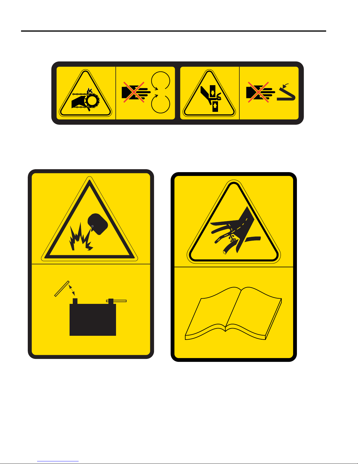
Rotating and moving parts.
Keep clear when engine is running.
Do not operate with steering tower cover removed.
Batteries produce explosive gases.
Keep sparks and flame away.
Disconnect negative terminal first.
Reconnect negative terminal last.
High Pressure fluid.
Leaks can penetrate sking.
Seek immediate medical attention for oil
penetration injury.
See Setup, Parts & Maintenance Manual for
proper methods to service hydraulic system.
Familiarize yourself with the following decals. They are critical to the safe operation of the
machine. REPLACE DAMAGED DECALS IMMEDIATELY.
11
Page 13
2000745
2000652
2000741
00223
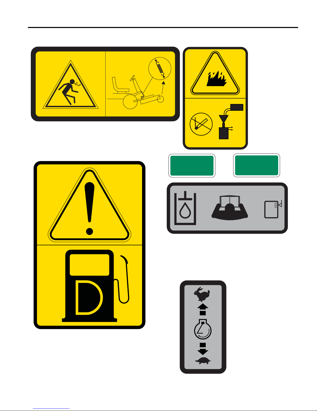
Restrained Forces.
Raise deck to relieve spring tension before
disconnecting a spring or its attachments.
When Refueling:
Stop Engine.
Do not smoke.
Do not spill fuel.
Do not overfill.
Allow 25 mm for
fuel expansion.
Diesel Fuel Only.
RETURN
00460
Maintain hydraulic fluid level at middle of sight
tube.
See Setup, Parts & Maintenance Manual for
proper hydraulic fluid.
Fast
Engine
Throttle
Slow
DECALS 4
2000641
PRESSURE
00459
12
Page 14
4 DECALS
2000742
2000647
RF
P
P
2000743
2000740
Keep air intake free of debris.
See mower manuals.
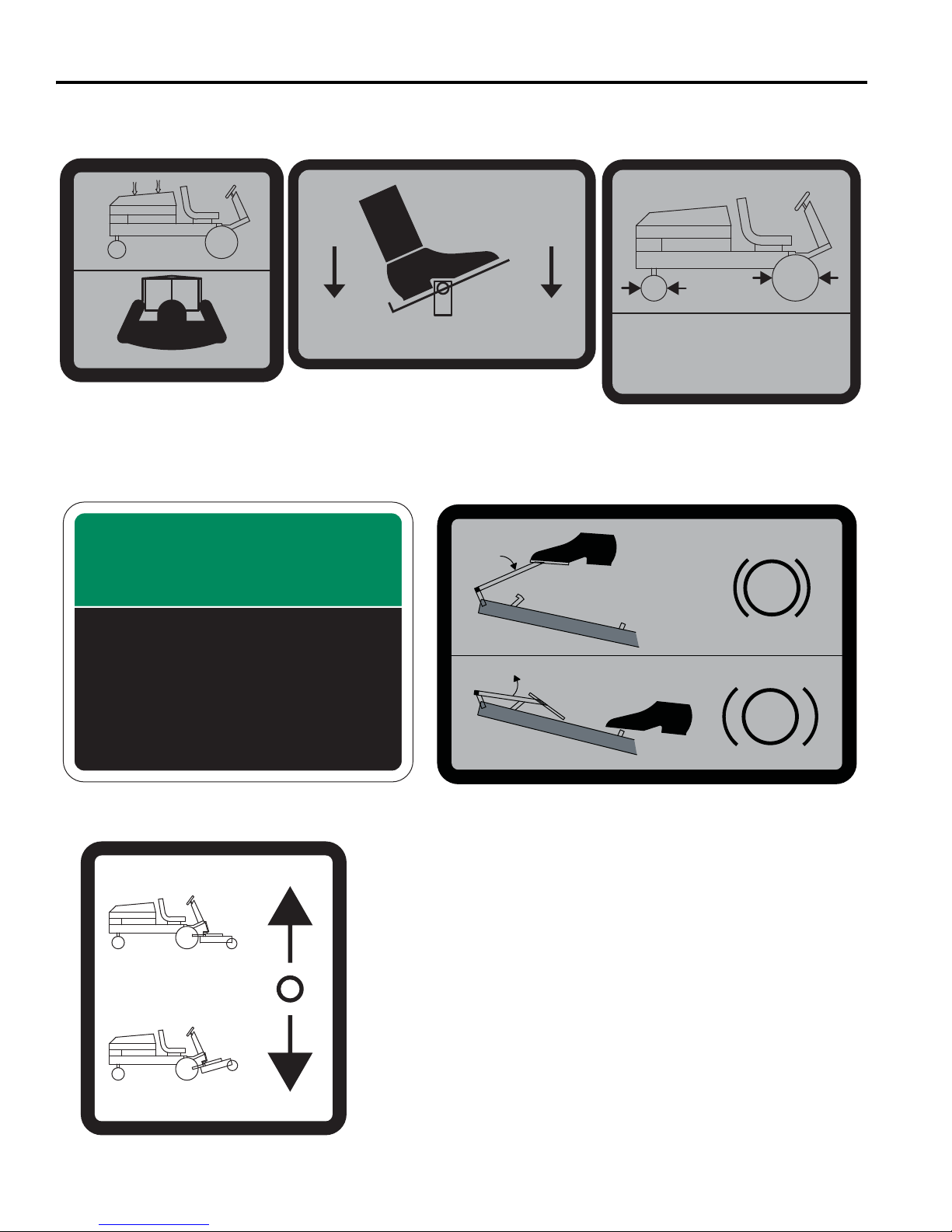
Press front of pedal for forward travel.
Push back of pedal for reverse travel.
Increased pedal movement causes
increased speed.
Maintain tire pressure at 1kg/cm
2
.
Read and understand Safety &
Operation Manual.
Press both pedals to engage parking brake.
Press parking brake release to disengage parking brake.
See Safety & Operation Manual.
Pull back on lever to lift cutting unit.
Push forward on lever to lower cutting
unit.
Familiarize yourself with the following decals. They are critical to the safe operation of the
machine. REPLACE DAMAGED DECALS IMMEDIATELY.
14 lb/in2 (1.0 kg/cm2)
2000688
NOTICE
WARRANTY
VOID IF SEAL IS
BROKEN
4117962
13
Page 15
DECALS 4
X
X
2722063
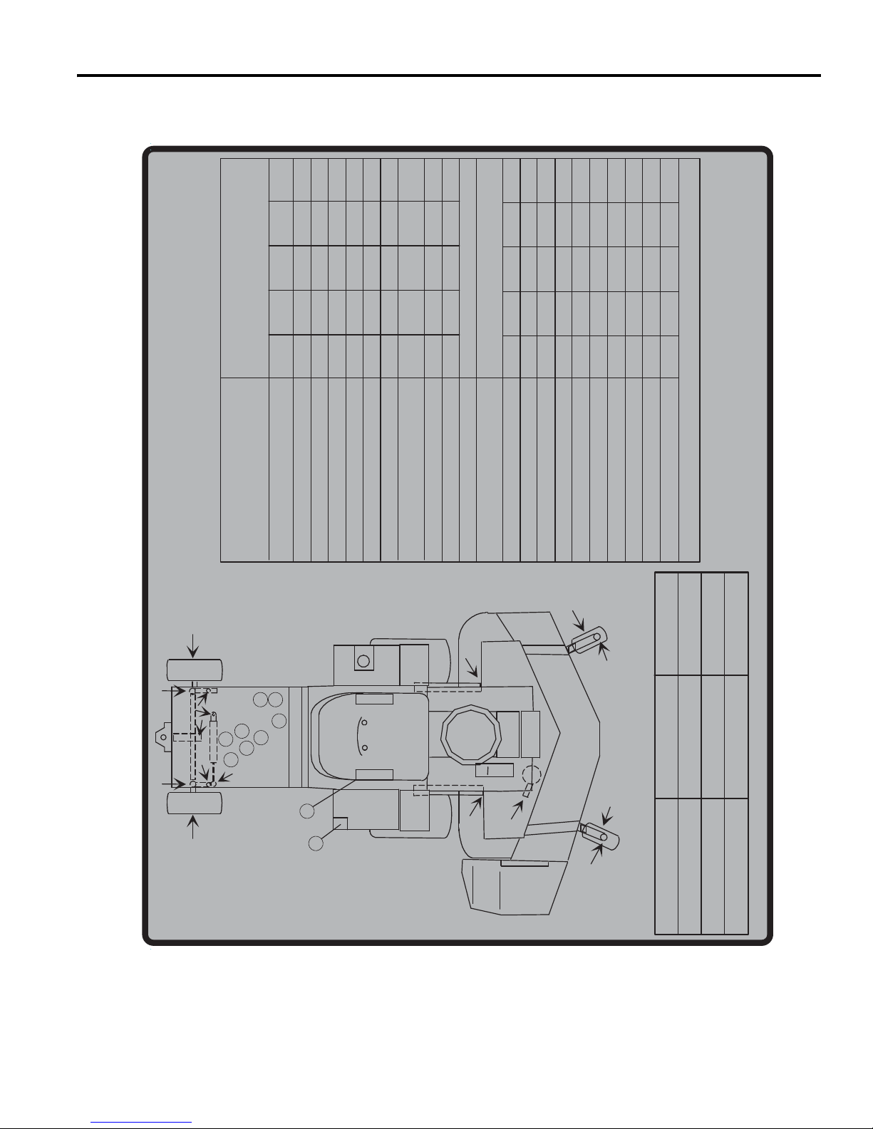
No service is a one-time job. These hours
2-WHEEL
DRIVE
ONLY
Hours of
Operation
80 100 400 600
DAILY
SERVICE MORE OFTEN
UNDER DIRTY CONDITIONS.
are intervals between EACH service.
Service Items
XXXXXXX
Check Interlock System
Check Engine Oil (1)
Check Hydraulic Oil Level (5)
Check Coolant Level (7)
Check Water Separater (6)
Check Tire Pressure
X
Clean Air Cleaner Particle Collector
Check/Clean Engine
Compartment, Radiator & Screen
X
Verify Cutter Deck Belt Tension
Every week
Lubricate Grease Fittings
ating conditions)
XXX
Every 400 hrs
(sooner for dirty oper
Replace Ait Cleaner Element (2)
Check/Top-up Battery
Check Fastner Tightness
Check Fan Belt Tension
XXX
X
Change Engine Oil & Filter (3)
Change Hydraulic Oil & Filter (4)
Service Engine Per Engine Manual
Change Fuel Filters (8)
X
Check Rear Wheel Toe-In
Drain & Clean Fuel Tank
(Trailing numbers show location on diagram for service items)
Drain & Flush Cooling System (9)
• Refer to engine manual for engine maintenance.
• Change engine oil, hydraulic oil and both oil filters FIRST 50 hours of operation.
SERVICE NOTES:
7
2-WHEEL
DRIVE
ONLY
10W30 SF-CD
10W30 SF-CD
6
8
2
3
1
3
50% ANTI-FREEZE
9
0.88 gallons (3.3 liters)
6.8 gallons (25.3 liters)
1.70 gallons (6.4 liters)
4
5
FLUID QUANTITY TYPE
ENGINE OIL
HYDRAULIC OIL
RADIATOR COOLANT
14
Page 16
4 DECALS
Familiarize yourself with the following decals. They are critical to the safe operation of the
machine. REPLACE DAMAGED DECALS IMMEDIATELY.
STOP
2721631
15
Page 17

INITIAL INSPECTION 5
!
!
5 INITIAL INSPECTION
5.1 GENERAL ________________________________________________________________
The inspection and testing of the unit should always be
performed by a trained technician, familiar with the
operation of this equipment.
Read each instruction completely and make sure you
understand it before proceeding. Stay alert for potential
hazards and obey all safety precautions.
The RIGHT and LEFT, FRONT, and REAR of the
machine are referenced from the operator’s seat, facing
forward.
Accessories not included with this product must be
ordered separately. See instructions provided with
accessory for installation and parts.
CAUTION
Do not attempt to drive the mower unless you are
familiar with this type of equipment and know how to
operate all controls correctly.
5.2 INITIAL INSPECTION _______________________________________________________
CAUTION
The initial inspection should be performed only when the engine is off and all fluids are cold. Lower mowers to the
ground, engage the parking brake, stop engine, and remove ignition key.
1. Perform a visual inspection of the entire unit. Look for
signs of wear, loose hardware, and components that
may have been damaged during transport.
5. Check tires for proper inflation. Tires have been over
inflated for transport. Correct tire pressure should be
set to
14 psi (1 BAR)
2. Inspect paint and decals for damage or scratches.
Decals provide important operating and safety
information. Notify dealer, and replace all missing,
damaged, or hard to read decals.
3. All fluids must be at the full level mark with engine
cold.
Check:
a. Radiator coolant level
b. Engine oil level
c. Hydraulic fluid level
4. Make sure air filter connections are tight and cover
is securely in place.
6. Check belt tension.
7. Inspect battery connections and electrolyte level.
Check that battery is fully charged.
8. Check for fuel or oil leaks.
9. Inspect lube points on deck and mower for proper
lubrication. [Parts & Maintenance Manual]
16
Page 18
6 CONTROLS
!
A
1
A
2
B
C
D
6 CONTROLS
6.1 PEDAL CONTROLS ______________________________________________________________
WARNING
Never attempt to drive the mower unless you have read the Safety & Operation Manual and know how to operate all
controls correctly.
Familiarize yourself with the icons shown above and what they represent. Learn the location and purpose of all the
controls and gauges before operating this mower.
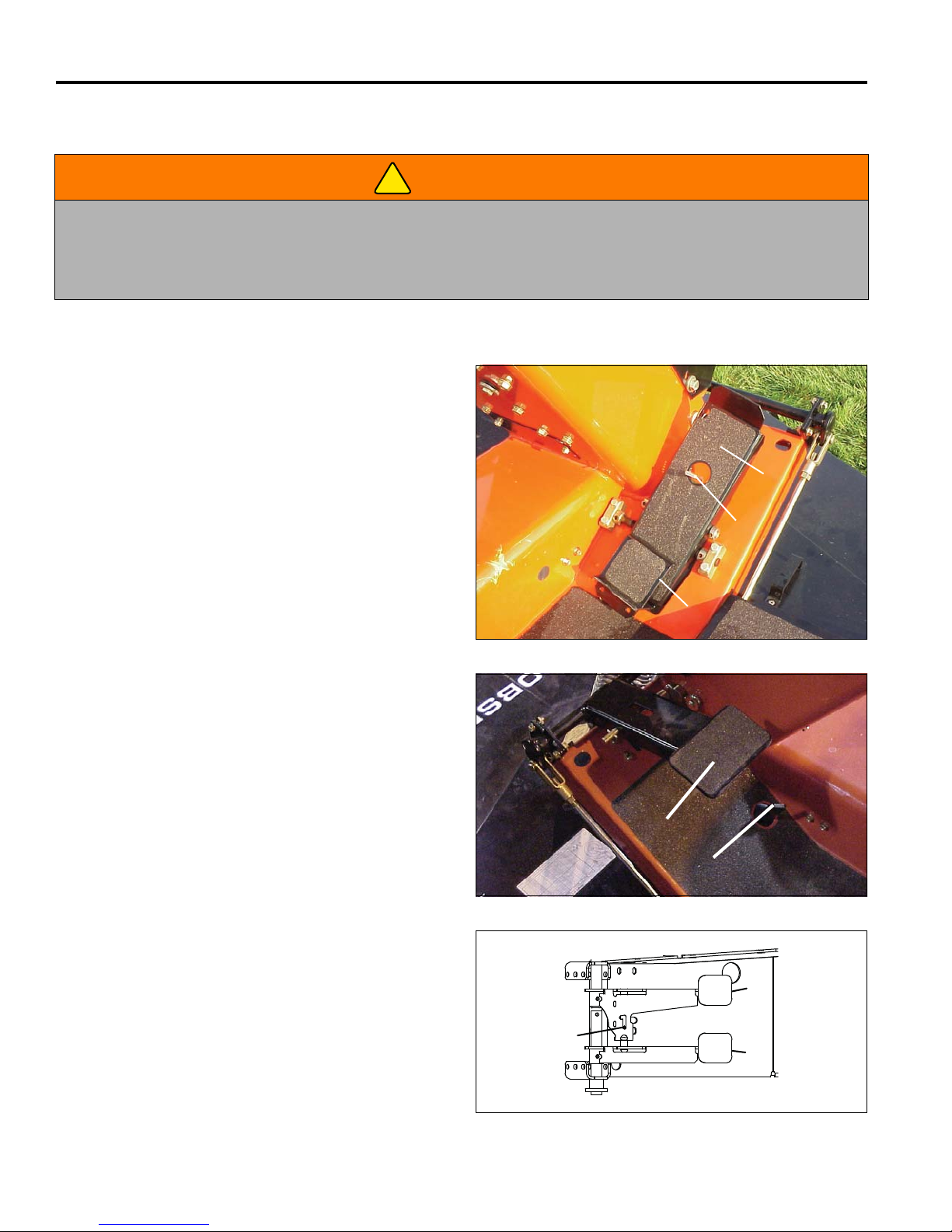
A. Traction Pedal
Used to control forward and reverse movement of
mower. Traction Pedal must be in neutral without
Neutral Latch (B) depressed to start the mower.
Press front pedal (A
) down for forward travel.
1
Release pedal to slow mower and stop.
Press rear pedal (A
) down for reverse travel.
2
Release pedal to slow mower and stop. Allow mower
to come to a complete stop before reversing
directions. Heel pad on rear pedal may be removed
for operators needing more leg room.
B. Neutral Latch
The Traction Pedal does not operate without
depressing Neutral Latch.
Press down on latch with your foot and move the
Traction Pedal in the desired direction. Remove your
foot from the pedal and the mower will stop and
Neutral Latch will engage.
C. Parking Brake
To engage Parking Brake press down on pedal until it
latches. Always engage Parking Brake before
starting and after stopping machine. Engine will not
start with Parking Brake disengaged.
Note: Pressing Turn Assist Pedal too hard will cause
wheel to lock up and may tear or mark the turf.
Figure 6A
D. Parking Brake Release
Releases the Parking Brake.
E. Turn Assist Pedals (Option)
Reduces the turning radius of the machine for
operation in close areas. Use the turn assist pedals
for making tight turns around trees and other objects.
Turn assist pedals will replace the Parking Brake
pedal. To use the parking brake, tie the pedals
together by sliding the lock pin (E
) above the pedals
3
toward the rear and to the left. Press both pedals
down at the same time to engage Parking Brake.
To operate turn assist, move lock pin to the right and
forward into the retaining notch (E
pedal down gradually until desired turning radius is
achieved - left pedal (E
) for right turns.
(E
2
) for left turns, right pedal
1
17
), press desired
3
Figure 6B
E
2
E
3
E
1
Figure 6C
Page 19
CONTROLS 6
F
G
H
M
J
N
R
K
L
P
6.2 CONTROL LEVERS ________________________________________________________
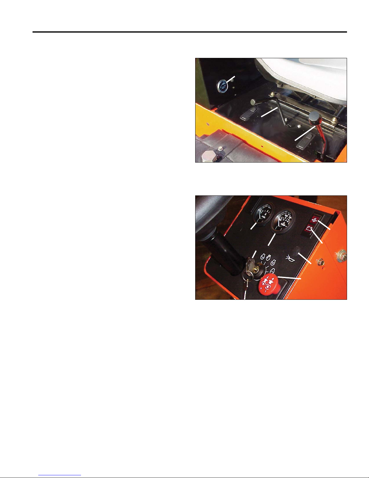
F. Lift Lever
Used to operate the hydraulic lift cylinder.
Pull the lever back and hold to raise the cutting unit.
Push the lever forward to lower the cutting unit. Hold
the lever for 1 to 2 seconds after the cutting unit
contacts the ground to fully extend the lift cylinder.
This allows the deck to further lower and adjust to
ground contours.
G. Throttle Lever
Controls the engine speed. Push lever forward to
increase engine speed, pull lever back for slower
engine speeds.
H. Hourmeter
Records total hours of engine operation.
Figure 6D
6.3 CONTROL PANEL _________________________________________________________
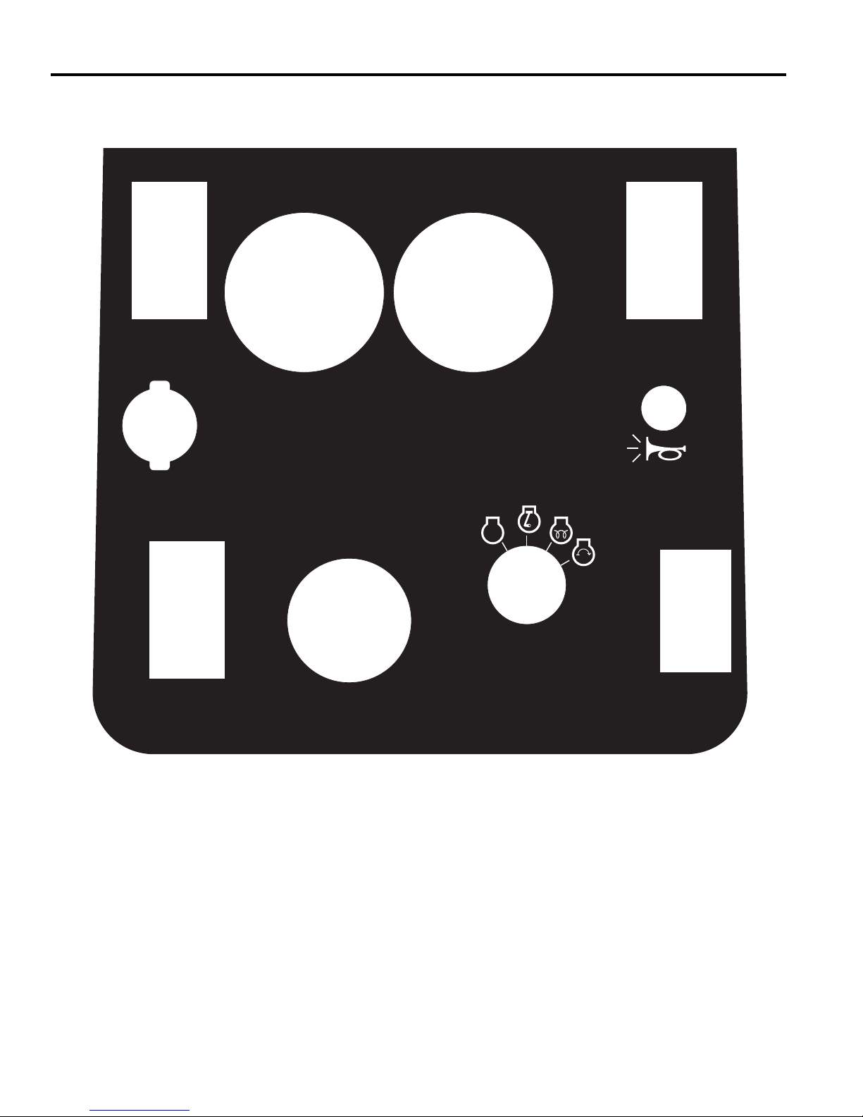
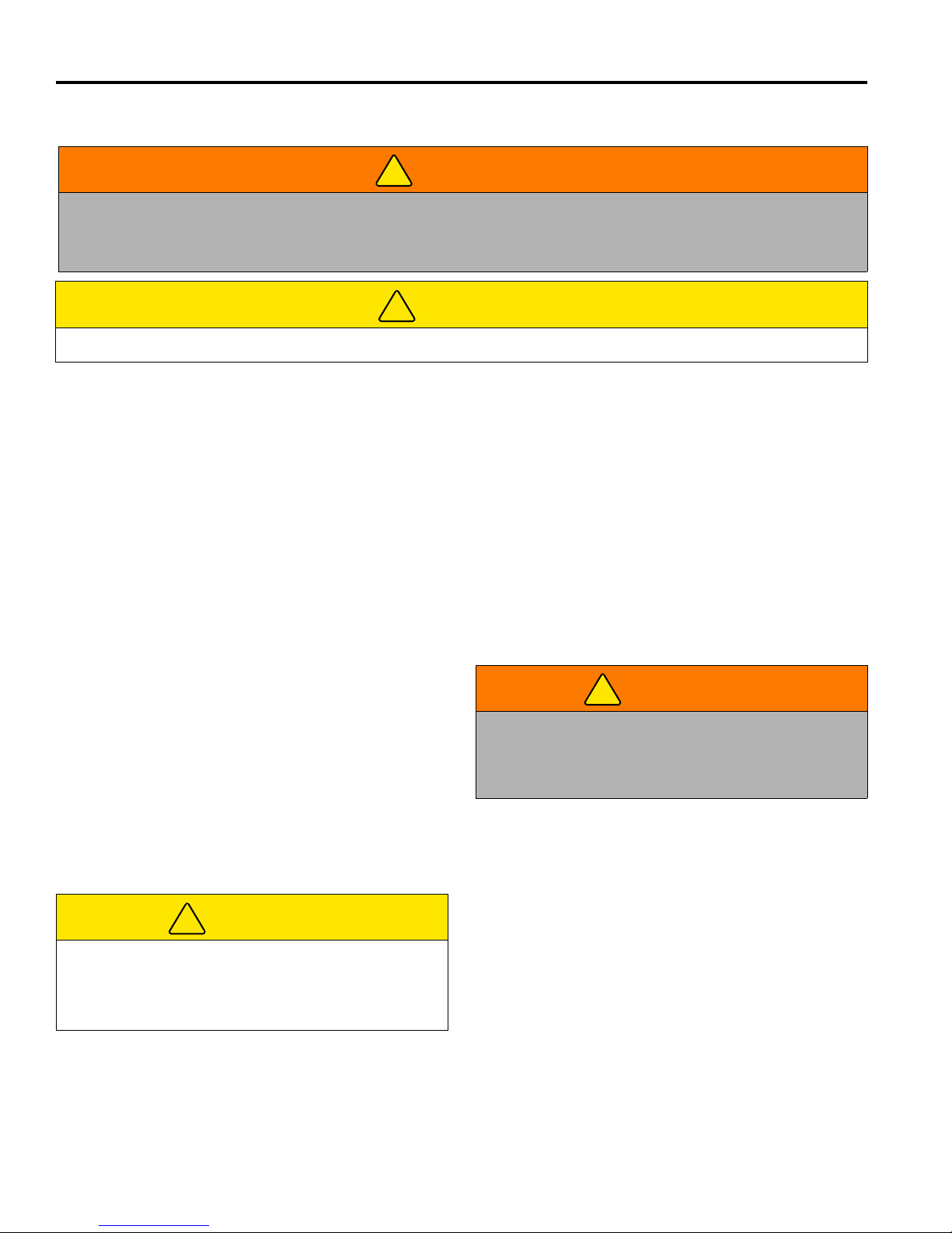
J. Ignition Switch
Used to energize the mower and start the engine.
Ignition switch has four positions, OFF, RUN, GLOW
PLUG, and START.
K. Power Take-Off (PTO) Switch
Used to engage and disengage the deck motor. Pull
up red knob to engage deck motor, push down to
disengage deck motor.
L. Horn Button (Option)
Used to sound the horn.
M. Engine Oil Pressure Light
Light will illuminate if engine oil pressure drops below
a safe operating level.
N. Alternator Light
Light will illuminate if engine alternator is not properly
charging the system.
P. Engine Temperature Gauge
Indicates engine coolant temperature. Normal
operating temperature should be between 160° 230°F (71°-110°C). If temperature rises above 230°
(110°F), alarm will sound. See Section 6.4.
Figure 6E
R. Fuel Gauge
Indicates current fuel level. Check fuel gauge daily
before starting machine.
18
Page 20

6 CONTROLS
6.4 OPERATOR ALERTS_______________________________________________________
The electrical system monitors vital machine systems. It
uses an audible alarm and warning lights to alert the
operator of conditions requiring immediate action. When
an alert occurs follow the general guidelines listed in the
chart below, and any specific actions outlined by the
grounds superintendent or service manager.
Alert Action
This system monitors:
1. Engine oil pressure.
2. Engine coolant temperature.
3. Driving with brake on.
1. Engine Oil Pressure - oil pressure light comes on. Oil pressure low.
2. Engine Coolant Temperature
Alarm sounds. Engine coolant
temperature high.
3. Alternator Light - Warning light
comes on.
4. Driving with brake on - Alarm
sounds.
Stop mower immediately, lower deck, and shut off engine! Inspect oil
level in engine. If oil light remains on with oil at proper level, shut off engine,
and tow or trailer mower back to a service area. NEVER operate engine with
oil light on, severe damage to the engine can occur.
Stop mower immediately, lower deck and shut off engine! Remove debris
such as leaves and grass clippings that may be restricting air flow through
rear screen on hood and area between radiator and oil cooler. If engine
continues to run hot, return mower to a service area.
CAUTION: Engine coolant is under pressure. Turn engine off and
allow fluid to cool before checking fluid level or adding coolant to
radiator.
Return mower to a service area as soon as possible. Inspect battery and
battery charging system.
Disengage parking brake, or remove foot pressure from either pedal.
Continued operation with both brake and traction pedal depressed may cause
damage to the braking system.
19
Page 21

OPERATION 7
!
!
7 OPERATION
7.1 DAILY INSPECTION ________________________________________________________
2. Check the fuel supply, radiator coolant level, crankcase
CAUTION
The daily inspection should be performed only when
the engine is OFF and all fluids are cold. Lower
mowers to the ground, engage the parking brake, stop
engine, and remove ignition key.
1. Perform a visual inspection of the entire unit, look for
signs of wear, loose hardware, and missing or damaged
components. Check for fuel or oil leaks to ensure
connections are tight and hoses and tubes are in good
condition.
7.2 INTERLOCK SYSTEM ______________________________________________________
1. The Interlock System prevents the engine from
starting unless the parking brake is engaged, traction
pedal is in Neutral, and the PTO switch is OFF. The
system also stops the engine if the operator leaves
the seat with the parking brake disengaged, PTO
switch ON, or traction pedal out of Neutral.
oil, and air cleaner indicator. All fluids must be at the
full level mark with engine cold.
3. Make sure all mowers are adjusted to the same cutting
height.
4. Visually check tires for proper inflation.
5. Test the interlock system.
Note: For more detailed maintenance information,
adjustments and maintenance/lube charts, see the
Parts & Maintenance manual.
3. Refer to the chart below for each test and follow the
check () marks across the chart. Shut engine off
between each test.
Test 1: Represents normal starting procedure. The
operator is seated, parking brake is engaged, the
operator’s feet are off the pedals, and the PTO switch
is OFF. The engine should start.
WARNING
Never operate equipment with the Interlock
System disconnected or malfunctioning. Do not
disconnect or bypass any switch.
2. Perform each of the following tests to insure the
Interlock system is functioning properly. Stop the
test and have the system inspected and repaired if
any of the tests fail as listed below:
the engine does not start in test 1;
the engine does start during tests 2, 3, or 4;
the engine continues to run during tests 5 or 6.
Interlock System Check
Test Operator
Seated
Yes No Yes No Yes No On Off Yes No
1
2
3
4
5
6
Horn will sound. Lift your weight off seat. The engine will shut down.
Traction Pedal
in Neutral
Lift your weight off seat. The engine will shut down.
Test 2: The engine must not start if the PTO switch is
ON.
Test 3: The engine must not start if the traction pedal
is pressed.
Test 4: The engine must not start if the parking brake
is disengaged.
Test 5: Start the engine in the normal manner then
turn PTO switch ON and lift your weight off the seat.
Test 6: Start the engine in the normal manner then
with parking brake engaged, slightly press the
traction pedal and lift your weight off the seat.
Parking Brake
Engaged
PTO
Switch
Engine
Starts
20
Page 22
7 OPERATION
!
!
!
!
7.3 OPERATING PROCEDURES_________________________________________________
WARNING
A Roll Over Protection Structure (ROPS) is included with this mower. Seat belts must be worn whenever operating
a mower with a ROPS. Always keep seat belt snugly adjusted. DO NOT use seat belts on a mower without a ROPS.
If the mower is overturning, hold onto the steering wheel. Do not attempt to jump out or leave the seat.
CAUTION
To prevent injury, always wear safety glasses, leather work shoes or boots, a hard hat, and ear protection.
1. Under no circumstances should the engine be
started without the operator seated on the mower.
Never start the engine with operator or bystanders
standing behind a discharge chute.
2. Never run the engine in an enclosed area.
3. Keep hands and feet away from moving parts and
cutting units. If possible, do not make adjustments with
the engine running.
4. Do not operate mower or attachments with loose,
damaged, or missing components. Whenever
possible mow when grass is dry.
5. First mow in a test area to become thoroughly
familiar with the operation of the mower and control
levers.
6. Study the area to determine the best and safest
operating procedure. Consider the height of the
grass, type of terrain, and condition of the surface.
Each condition will require certain adjustments or
precautions.
7. Be aware of mower discharge direction and never
direct discharge of material toward bystanders.
Never allow anyone near the machine while in
operation. The owner/operator is responsible for
injuries inflicted to bystanders and/or damage to
their property.
CAUTION
Before mowing, pick up all debris such as rocks, toys,
and wire which can be thrown by the machine. Enter a
new area cautiously. Always operate at speeds that
allow you to have complete control of the mower.
8. Use discretion when mowing near gravel areas
(roadway, parking areas, cart paths, etc.). Stones
discharged from the implement may cause serious
injuries to bystanders and/or damage the
equipment.
9. Always turn PTO switch OFF to stop blades when
not mowing.
10. Disengage the drive motors, raise the mowers, and
slow down when crossing paths or roadways. Look
out for traffic.
11. Stop and inspect the equipment for damage
immediately after striking an obstruction, or if the
machine begins to vibrate abnormally. Have the
equipment repaired before resuming operation.
WARNING
Before you clean, adjust, or repair this equipment,
always disengage all drives, lower implements to the
ground, engage parking brake, stop engine, and
remove key from ignition switch to prevent injuries.
12. Slow down and use extra care on hillsides. Read
Section 7.7. Use caution when operating near drop
offs.
13. Look behind and down before backing up to be sure
the path is clear. Use care when approaching blind
corners, shrubs, trees, or other objects that may
obscure vision.
14. Never use your hands to clean cutting units. Use a
brush to remove grass clippings from blades. Blades
are extremely sharp and can cause serious injuries.
21
Page 23
OPERATION 7
STOP
M
J
N
K
7.4 STARTING________________________________________________________________
position for more than 5 seconds, or in the START
NOTICE
IMPORTANT: Do not use starting assist fluids. Use of
such fluids in the air intake system may be potentially
explosive or cause a “Runaway” engine condition and
could result in serious engine damage.
The engine is equipped with an air intake heating system.
This system does not require glow plugs to start the
engine.
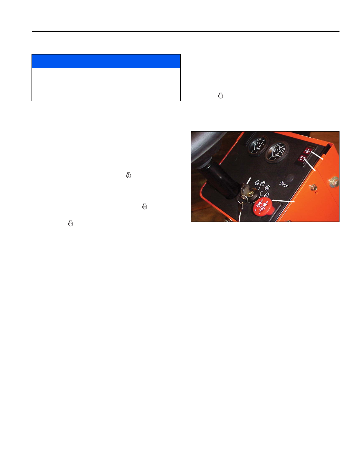
1. Sit in operator’s seat, make sure the PTO switch (K)
is OFF, and the parking brake is engaged. Remove
feet from pedals. Always use the seat belt when
operating mowers equipped with a ROPS.
2. Set throttle lever (G) to half throttle.
3. Turn ignition switch (J) to RUN ( ).
At this time the engine oil pressure and alternator
lights (M and N) will come on.
position for more than 15 seconds. Energizing glow
plugs is not necessary when starting a warm
engine.
If engine fails to start, return ignition switch to the
OFF ( ) position. Allow 30 seconds between startup attempts to allow time for engine starter motor to
cool.
5. All warning lights should go off after engine starts.
4. Turn ignition switch to GLOW PLUG ( ) position for
about 3 to 5 seconds, then turn key to START
position ( ). Release as soon as engine starts. The
colder the temperature, the longer it will take to
energize plugs. Do not hold switch in GLOW PLUG
Figure 7A
7.5 STOPPING / PARKING______________________________________________________
To stop:
Remove your foot from traction pedal. The mower will
automatically brake when the traction pedal returns to
Neutral.
To park the mower under normal conditions:
1. Disengage the PTO switch (K), raise the decks, and
move away from the area of operation.
2. Select a flat and level area to park.
a. Release traction pedal to bring the mower to a
complete stop.
b. Disengage all drives, lower decks to the ground,
reduce throttle to idle, and allow engine to operate at no load for a minute.
3. Engage parking brake, stop the engine and always
remove the ignition key.
If an emergency arises and the mower must be parked in
the area of operation, follow the guidelines outlined by
the grounds superintendent. If the mower is parked on an
incline, chock or block the wheels.
22
Page 24
7 OPERATION
!
!
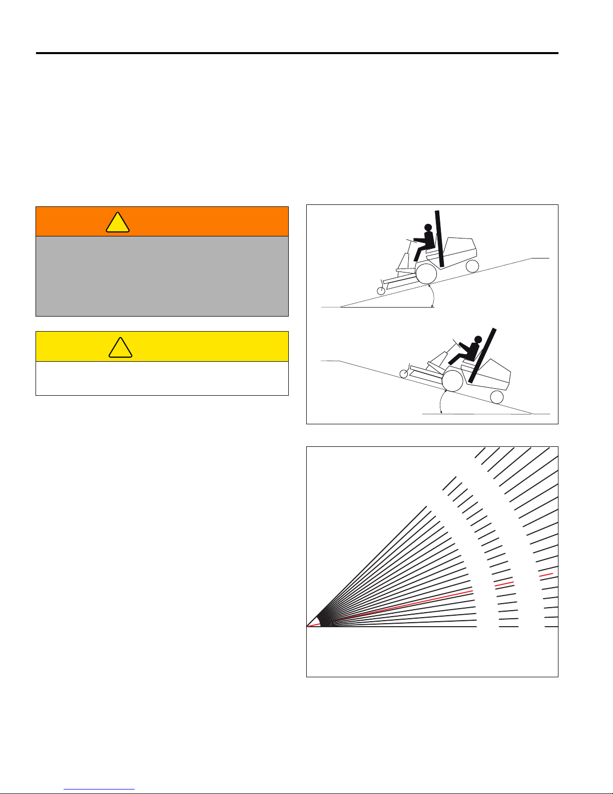
15° Maximum
15° Maximum
0°
Degrees are shown to nearest 1/4°
General Slope of Roadway Embankment - 45°
Steepest Grass Area - 31°
Slope of Average Roof - 19-1/4°
2nd Class Highway Maximum Grade - 4-1/2°
Toll Road or Freeway - 1-3/4°
0%
2-3/4°
5%
5-3/4°
10%
8-1/2°
15%
11-1/4°
20%
14°
25%
16-3/4°
30%
19-1/4°
35%
21-3/4°
40%
24-1/4°
45%
26-1/2°
50%
28-3/4°
55%
31°
60%
33°
65%
35°
70%
36-3/4°
75%
38-3/4°
80%
40-1/4°
85%
42°
90%
43-1/2°
95%
45°
100%
Degrees
Grade
7.6 TO DRIVE / TRANSPORT____________________________________________________
Read and follow all safety notes contained in this manual
when driving or transporting mower. Refer to Section 7.3
for general operating instructions. When operating in
reverse look behind you to ensure you have a clear path.
Important: If this mower is driven on public roads, it must
comply with federal, state, and local ordinances. Contact
local authorities for regulations and equipment
requirements.
To raise decks to their transport position:
Set PTO switch to OFF. Pull back and hold lift lever until
deck is fully raised (transport) position.
7.7 HILLSIDE OPERATION _____________________________________________________
WARNING
To minimize the possibility of overturning, the safest
method for operating on hills and terraces is to travel
up and down the face of the slope (vertically), not
across the face (horizontally). Avoid unnecessary
turns, travel at reduced speeds, and stay alert for
hidden hazards.
CAUTION
Do not operate this mower on slopes greater than 15°
or 26.8% grade.
The mower has been designed for good traction and
stability under normal mowing conditions; however, use
caution when operating on slopes, especially over rough
terrain or when the grass is wet. Wet grass reduces
traction and steering control.
1. Always mow with the engine at full throttle but reduce
forward speed to maintain the proper cutting
frequency.
2. If the mower tends to slide or the tires begin to
“mark” the turf, angle mower into a less steep grade
until traction is regained or tire marking stops.
3. If mower continues to slide or mark the turf, the
grade is too steep for safe operation. Do not make
another attempt to climb, back down slowly.
4. When descending a steep slope, always lower
implements to the ground to reduce the risk of
mower overturning.
Correct tire pressure is essential for maximum traction. Keep
tires inflated to 14 psi (1 BAR).
23
Figure 7B
Figure 7C
Page 25
OPERATION 7
C
A
B
D
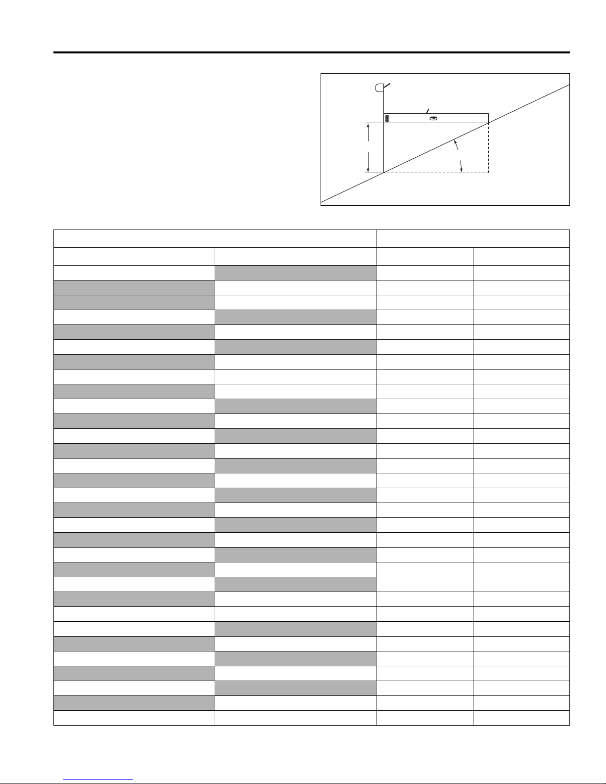
How to calculate a slope:
Tools Required:
Level (A), either 1 yard, or 1 meter long.
Tape measure (B).
With the level (A) positioned horizontally, measure the
distance (C) with tape measure (B). Use the chart to
calculate eirther the slope angle or the % grade of the
slope (D).
Height (C) Result (D)
Inches with 1 Yard Level (A) Millimeters with 1 Meter Level (A) Slope in Degrees Slope Grade %
Figure 7D
3
100 5.7 10.0
150 8.5 15
6
200 11.3 20.0
7.5
225 12.7 22.5
9 250 14 25.0
275 15.4 27.5
10
300 16.7 30.0
11
325 18.0 32.5
12
350 19.3 35.0
13
375 20.6 37.5
14
400 21.8 40.0
15
425 23.0 42.5
16
475 25.4 47.5
18 500 26.6 50.0
20
600 31.0 60.0
25
800 38.7 80.0
30
900 42.0 90
36 1000 45.0 100
4.8 8.3
9.5 16.7
11.8 20.8
15.5 27.8
17.0 30.6
18.4 33.3
19.9 36.1
21.3 38.9
22.6 41.7
24 44.4
29.1 55.6
34.8 69.4
39.8 83.3
24
Page 26
7 OPERATION
!
!
7.8 MOW SPEED _____________________________________________________________
Cutting quality is better at speeds well below the
transport speed of the mower. An initial mow speed of 5
to 6 mph (8 to 9.6 kph) is set at the factory and should be
satisfactory for most cutting conditions. Local turf
conditions however may respond better to a different
speed.
7.9 MOWING_________________________________________________________________
WARNING
To prevent serious injuries, keep hands, feet, and
clothing away from cutting unit when the blades are
moving.
NEVER use your hands to clean cutting units. Use a
brush to remove grass clippings from blades. Blades
can be sharp and could cause injuries.
To clear obstructions from cutting unit, disengage
PTO, engage parking brake, stop engine, and remove
key from ignition switch then remove obstruction.
To mow:
1. Press lift lever (F) forward to lower decks. Engage
PTO (K) to start blades and depress traction pedal
slowly to begin mowing.
To set mow speed, loosen jam nut and adjust stop screw,
located under the traction pedal, up to reduce speed,
down to increase speed. Tighten nut to hold adjustment
in place.
The correct operating speed depends on the height,
density, type of grass and terrain being cut.
2. To raise decks first turn PTO switch (K) off to stop
blades, then pull and hold lift lever (F) back. Always
stop and raise decks when crossing paths or
roadways.
CAUTION
Never raise decks with the blades turning. Always
disengage PTO.
3. Plan your cutting pattern to avoid unnecessary turns
so you will mow as straight as possible.
a. For extremely tall grass, first cut at a higher level
then lower decks to the desired cutting height.
b. Slow down when turning, operating in tight areas,
7.10 AFTER OPERATION _______________________________________________________
1. Park the mower on a flat, level surface. Fully lower
the implements to the ground, engage parking brake,
stop the engine, and remove key from ignition switch.
2. Grease and lubricate all points if required, wash the
cutting unit and mower after each use.
Note: Do not wash a hot or running engine. Use
compressed air to clean the engine and radiator fins.
3. Fill the fuel tank with fresh, clean fuel. Be sure to
reinstall and tighten fuel cap.
Read Parts and Maintenance Manual for proper care
and cleaning procedures.
25
Page 27
OPERATION 7
U
S
T
7.11 TOWING / TRAILERING _____________________________________________________
If the mower experiences problems and must be shut
down and removed from the area, it should be loaded
onto a trailer for transport. If a trailer is not available, the
unit can be towed slowly short distances.
Use care when loading and unloading mower. Fasten
mower to trailer to prevent mower from rolling or shifting
during transport.
Long Distance Trailering / Transport. If the mower is to
be trailered on the highway, before strapping to trailer,
close fuel shut off valve, and inflate tires to the maximum
pressure listed on side of tire. Reduce tire pressure to
normal after removing from trailer.
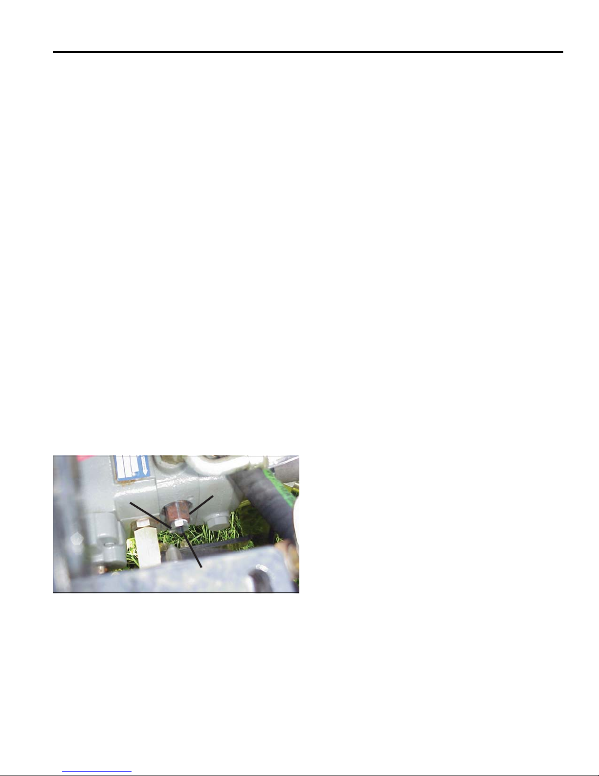
Before towing, open tow valve. The tow valve permits
moving the mower without starting the engine and
prevents possible damage to hydraulic components.
The tow valve (U) is located on the hydraulic drive pump
beneath the operators seat. To open valve, loosen jam
nut (S), and hold while hex stud (T) is backed out 3 to 4
turns. Do not loosen or remove tow valve body (U).
Before towing make sure deck is raised. If deck cannot
be raised, remove it from the mower.
Turn the hex stud (T) fully in and tighten jam nut (S) after
towing.
NOTE: Do not exceed 2 MPH (3.2 KPH) while towing. Long
distance towing is not recommended
.
Figure 7E
26
Page 28

7 OPERATION
!
7.12 DAILY MAINTENANCE _____________________________________________________
Important: For more detailed maintenance information,
adjustments and maintenance/lubrication charts, see the
Parts& Maintenance manual.
1. Park the mower on a flat and level surface. Fully
lower the cutting units to the ground, engage parking
brake, stop the engine, and remove the key from ignition switch.
2. Grease and lubricate all points if required. To
prevent fires, wash the cutting units, and mower
after each use.
a. Do not use high pressure spray.
b. Do not spray water directly at the instrument
panel, or any electrical components.
c. Do not spray water into cooling air intake, or the
engine air intake.
Note: Do not wash a hot or running engine. Use
compressed air to clean the engine and radiator fins.
3. Fill the mowers fuel tan at the end of each operating
day to within 1 in., (25 mm) below the filler neck.
To prevent serious injury from hot, high pressure oil,
never use your hands to check for oil leaks, use paper
or cardboard.
Hydraulic fluid escaping under pressure can have
sufficient force to penetrate skin. If fluid is injected
into the skin, it must be surgically removed within a
few hours by a doctor familiar with this form of injury
or gangrene may result.
6. Inspect hydraulic hoses and tubes daily. Look for
wet hoses or oil spots and replace worn or
damaged hoses and tubes before operating the
machine.
7. Check the engine oil and hydraulic oil at the start of
each day, before starting the engine. If the oil level
is low, remove the oil filler cap and add oil as
required. Do not overfill.
WARNING
Use clean fresh #2 low or ultra low sulfur diesel fuel.
Minimum Cetane Rating 45.
4. Handle fuel with care - it is highly flammable. Use
an approved container, the spout must fit inside the
fuel filler neck. Avoid using cans and funnels to
transfer fuel.
a. Never remove the fuel cap from the fuel tank, or
add fuel, when the engine is running, or while the
engine is hot.
b. Do not smoke when handling fuel. Never fill or
drain the tank indoors.
c. Never overfill or allow the tank to become empty.
Do not spill fuel. Clean any spilled fuel
immediately.
d. Never handle or store fuel containers near an
open flame or any device that may create sparks
and ignite the fuel or fuel vapors.
5. Store fuel according to local, state, or federal
ordinances and recommendations from your fuel
supplier.
27
Page 29
MAINTENANCE & LUBRICATION CHARTS 8
!
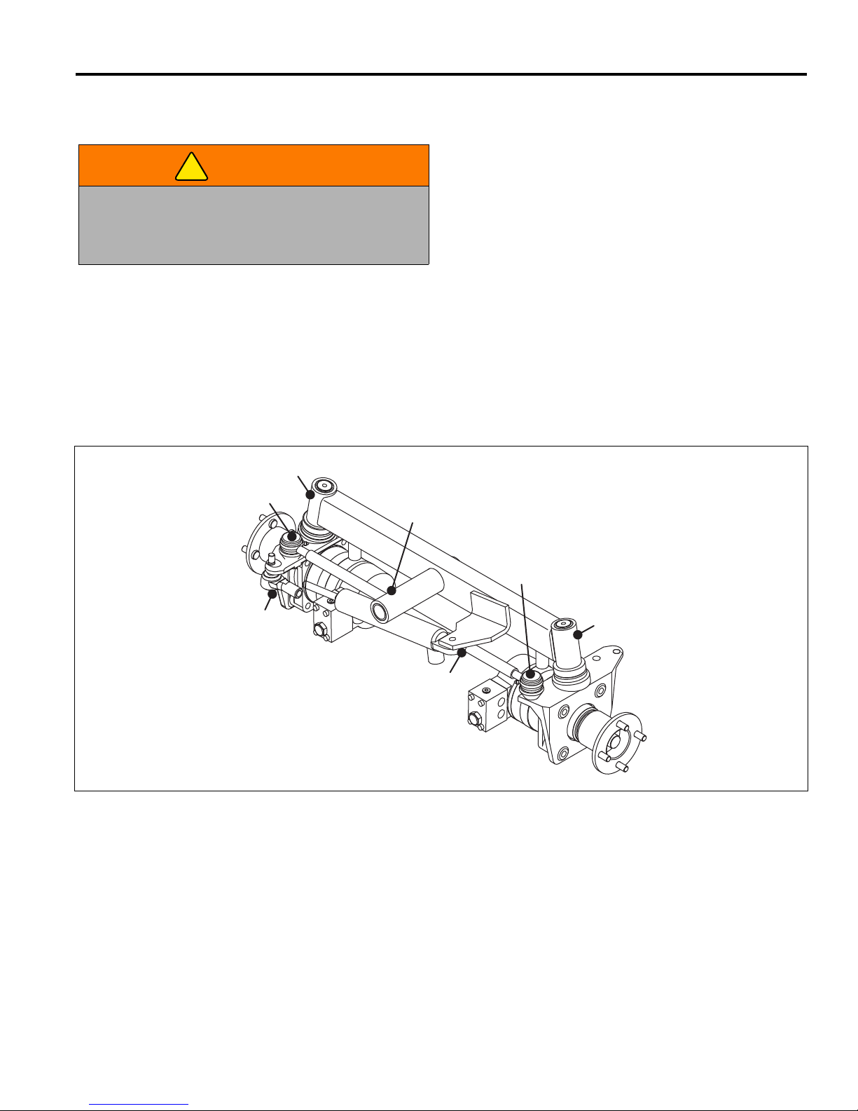
A - Steering Axle Pivot
B - Steering Spindle Pivot (2)
C - Steering Cylinder (2)
D - Tie Rod (2)
A
B
B
C
C
D
D
8 MAINTENANCE & LUBRICATION C HARTS
8.1 GENERAL ________________________________________________________________
2. Lubricate with grease that meets or exceeds NLGI
WARNING
Before you clean, adjust, or repair this equipment
disengage all drives, lower implements to the ground,
engage parking brake, stop engine, and remove key
from ignition switch to prevent injuries.
1. Always clean the grease fitting before and after
lubricating.
8.2 LUBRICATION CHART______________________________________________________
Grade 2 LB specifications. Apply grease with a
manual grease gun and fill slowly until grease begins
to seep out. Do not use compressed air guns.
3. Periodically apply a small amount of lithium based
grease to the seat runners.
4. For smooth operation of all levers, pivot points and
other friction points that are not shown on the
lubrication chart apply several drops of SAE 30 oil
every 40 hours or as required.
5. Grease fittings every 40 hours.
28
Page 30

8 MAINTENANCE & LUBRICATION CHARTS
8.3 MAINTENANCE CHARTS ___________________________________________________
Recommended Service and Lubrication Intervals
Air Filter
Battery Charge
Belts (Alternator and Deck)
Brake
Cooling System
Electrical System
Engine Oil (Diesel)
Engine Oil Filter
Fuel System
Fuel Filter
Fuel Water Separater
Grease Fittings - All
Hydraulic Hoses and Tubes
Hydraulic Oil
Hydraulic Oil Filter
Interlock System
Muffler and Exhaust
Radiator Screens
Tires
Every
8-10
Hours
Every
50
Hours
Every
100
Hours
Every
250
Hours
Every
400
Hours
Every
500
Hours
Every
1000
Hours
Yearly See
Section
Lubricant
Typ e
IR**R9.4
I9.9
I-A* I-A R 10.3
I-A* A 10.2
I-C-A R 9.19 IV
I* I 9.14
IR*R 9.3 II
R* R
I C****
R9.6
I9.6
L8.2I
I*** I 9.12
I-A R 9.13 III
I R 9.13
I-A
I I 9.15
I-C/AR 9.19
I-A 9.16
A - Add or Adjust C - Clean I - Inspect L- Lubricate R - Replace AR - As Required
* Indicates initial service for new machines.
** Sooner for dirty operating conditions.
*** Inspect visible hoses and tubes for leaks or oil marks.
**** Drain and clean fuel tank.
I - Manual grease gun with NLGI Grade 2 (Service Class
LB).
II - Engine Oil - See Section 9.4
III - Use Jacobsen hydraulic fluid: Capacity: 5 gallons
(19 Liters). Order Part No. 2500548 carton, containing
two 2-1/2 gal. (9.5 liter) bottles or Part No. 2500546
containing 5 gal. (19 liters), pail.
IV - 50/50 water ethylene glycol mix.
29
Page 31

MAINTENANCE 9
!
9 MAINTENANCE
9.1 GENERAL ________________________________________________________________
b. Keep all moving parts properly adjusted and
WARNING
Before you clean, adjust, or repair this equipment,
disengage all drives, lower implements to the ground,
engage parking brake, stop engine, and remove key
from ignition switch to prevent injuries
Make sure the mower is parked on a solid and level
surface. Never work on a mower that is supported
only by the jack. Always use jack stands.
1. Adjustment and maintenance should always be
performed by a qualified technician. If proper
adjustments cannot be made, contact an Authorized
Jacobsen Dealer.
2. Inspect the equipment on a regular basis, establish
a maintenance schedule, and keep detailed records.
a. Keep the equipment clean.
3. Long hair, jewelry or loose fitting clothing may get
4. Use the illustrations in the Parts Catalog as
5. Recycle or dispose of all hazardous materials
lubricated.
c. Replace worn or damaged parts before operating
the machine.
d. Keep all fluids at their proper levels.
e. Keep shields in place and all hardware securely
fastened.
f. Keep tires properly inflated.
tangled in moving parts.
reference for the disassembly and reassembly of
components.
(batteries, fuel, lubricants, anti-freeze, etc.)
according to federal, state, or local regulations.
9.2 ENGINE _________________________________________________________________
IMPORTANT: A separate Engine Manual, prepared by
the engine manufacturer, is supplied with this mower.
Read the Engine Manual carefully until you are familiar
with the operation and maintenance of the engine.
Proper attention to the engine manufacturer’s directions
will assure maximum service life of the engine. To order
a replacement Engine Manual contact the engine
manufacturer.
The proper break-in of a new engine can make a
considerable difference to the performance and life of the
engine.
Note: The mower is designed to operate and cut most
efficiently at the preset governor setting. Do not change
the engine governor settings or overspeed the engine.
During the break-in period, Jacobsen recommends the
following:
1. During the first 50 hours of operation, a new engine
should be allowed to reach an operating temperature
of at least 140°F (60°C) prior to operation at full load.
2. Check the engine oil level twice daily during the first
50 hours of operation. Higher than normal oil
consumption is not uncommon during the initial
break-in period.
3. Change engine oil and oil filter element after first 50
hours of operation.
4. Check and adjust alternator belt.
5. Refer to Section 8.3 and Engine Manual for specific
maintenance intervals.
If the injection pump, injectors, or the fuel system require
service, contact an authorized Jacobsen Dealer.
9.3 ENGINE OIL ______________________________________________________________
Check the engine oil at the start of each day, before
starting the engine. If the oil level is low, remove oil filler
cap, and add oil as required.
Use only engine oils with API classification CD/CE.
Above 77°F (25°C) SAE 30W or SAE10W30/10W40
Perform initial oil change after first 50 hours of operation
and every 100 hours thereafter. See Engine Manual.
32 to 77°F (0 to 25°C) SAE 20W or SAE 10W30/10W40
Below 32° (0°C) SAE10W or SAE 10W30/10W40
30
Page 32

9 MAINTENANCE
!
9.4 AIR FILTER_______________________________________________________________
Do not remove the element for inspection or
cleaning. Unnecessary removal of the filter increases
the risk of injecting dust and other impurities into the
engine. Refer to Section 8.3 for specific maintenance
intervals.
When service is required, first clean the outside of the
filter housing; then remove the old element as gently as
possible and discard.
1. Carefully clean the inside of the filter housing without
allowing dust into the air intake.
2. Inspect the new element. Do not use a damaged
element and never use an incorrect element.
3. Assemble the new element and make sure it seats
properly.
4. Reassemble cap making sure it seals completely
around the filter housing. Dust evacuator must be
facing down.
5. Check all hoses and air ducts. Tighten hose clamps.
9.5 FUEL ____________________________________________________________________
Handle fuel with care - it is highly flammable. Use an
approved container, the spout must fit inside the fuel filler
neck. Avoid using cans and funnels to transfer fuel.
WARNING
Never remove the fuel cap from the fuel tank, or add
fuel, when the engine is running or while the engine is
hot.
• Fill the fuel tank to full mark on fuel gauge.
• Store fuel according to local, state, or federal
ordinances and recommendations from your fuel
supplier.
• Never overfill or allow the tank to become empty.
• Check fuel lines and clamps every 50 hours. Replace
fuel lines and clamps at the first sign of damage.
Do not smoke when handling fuel. Never fill or drain
the fuel tank indoors.
Do not spill fuel and clean spilled fuel immediately.
Never handle or store fuel containers near an open
flame or any device that may create sparks and ignite
the fuel or fuel vapors.
Be sure to reinstall and tighten fuel cap securely.
• Use clean fresh #2 Low or Ultra Low Sulfur Diesel fuel.
Minimum Cetane rating 45. Refer to Engine Manual for
additional information.
31
Page 33
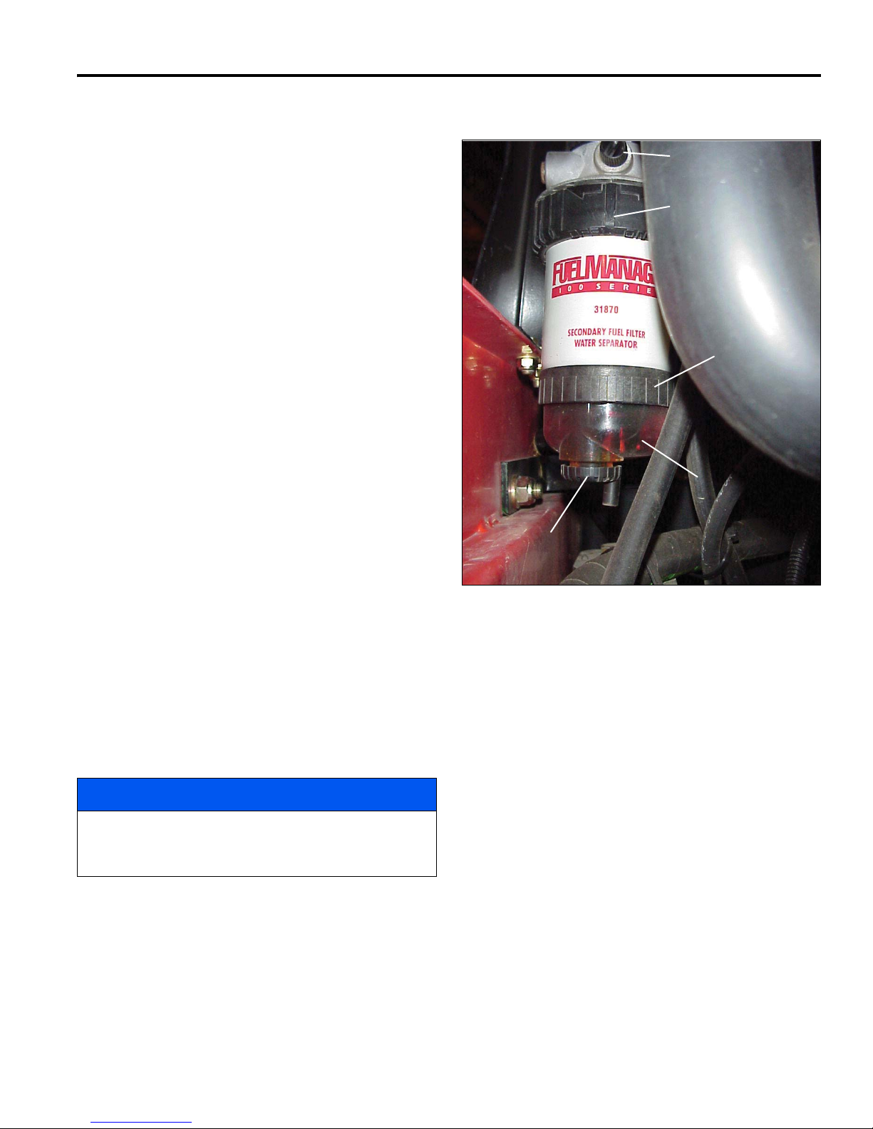
MAINTENANCE 9
A
B
C
D
E
9.6 FUEL MANAGER __________________________________________________________
Refer to Section 8.3 for specific maintenance intervals.
Before replacing any filter, thoroughly clean the filter
housing and the area around the filter. Dirt must not be
allowed to enter into fuel system.
Bleed the fuel system if the water separater, fuel filter, or
hoses have been removed, or the fuel tank has become
empty.
Water Separater:
This mower is equipped with a fuel separater that traps
the water in the fuel. If the water is not removed from the
fuel system, extensive damage can occur in the fuel
injection system.
The fuel separater can be removed from the fuel
manager by holding black grip ring (C) and turning water
separater counter-clockwise.
Water will collect at the bottom of the see-through bowl
(A) and appear a different color than the fuel. To drain
water from the water separater:
1. Place a small container under drain valve (B).
2. Open drain valve (B) and allow the water to drain
into the container.
3. Retighten drain valve and clean up any spilled fuel
or water.
4. Bleed air from the fuel system.
Fuel Filter:
1. Remove the water separater.
2. Remove black retaining ring (D).
3. Pull the fuel filter straight down. Do not twist the fuel
filter when removing. Dispose of the old filter
element according to local regulations.
NOTICE
The fuel filter is not threaded and damage to the fuel
manager or filter may result by attempting to turn the
filter during removal or installation.
4. Align key if filter element with the slot in the header
and push the new filter element up in the center of
the fuel manager.
Figure 9A
5. Install retaining ring (D). Hand tighten retaining ring
until it clicks and the arrows line up under the air
vent (E).
6. Bleed air from the fuel system.
32
Page 34
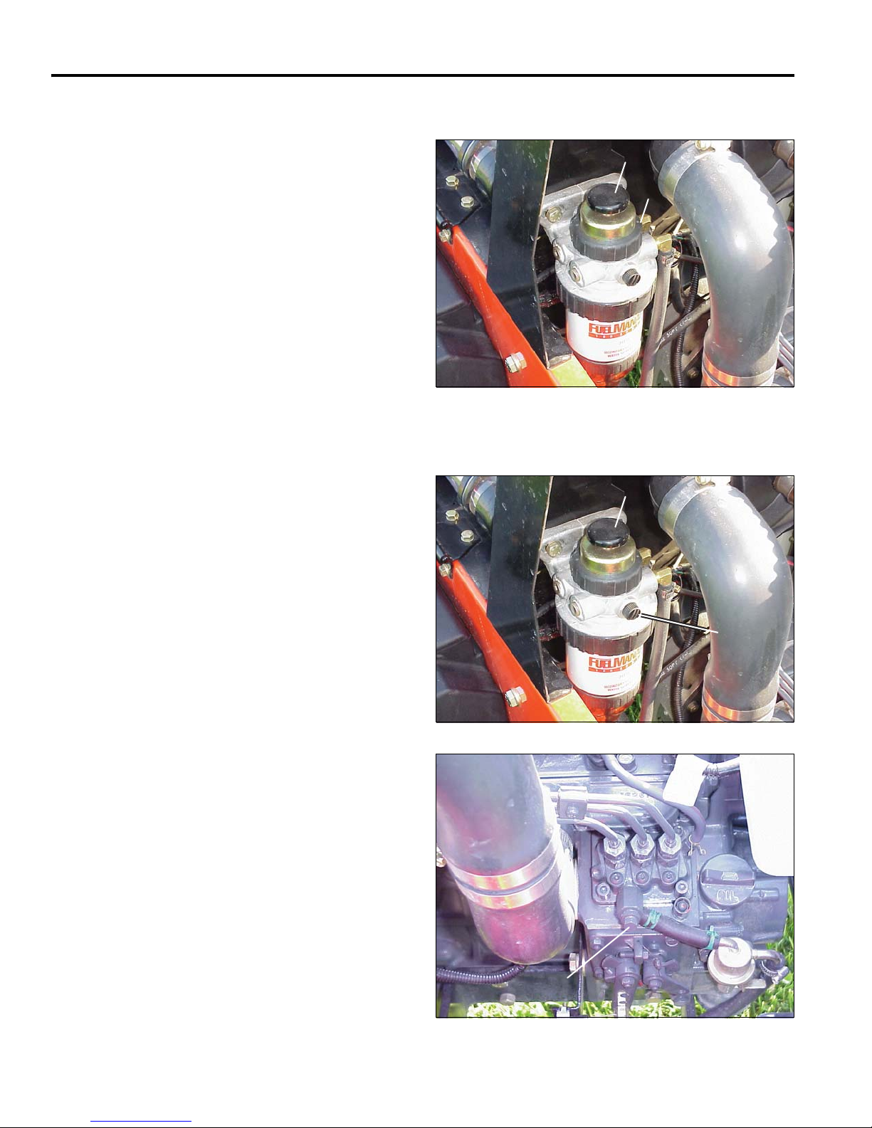
9 MAINTENANCE
F
G
F
E
G
9.7 HAND PRIMER PUMP ______________________________________________________
The hand primer pump (F) is used to purge air from the
fuel system. The entire pump assembly is replaceable if
necessary. See the parts list for fuel manager service
parts.
1. Carefully remove the black retaing ring. The primer
pump is spring loaded.
2. Remove hand pump components and replace with
new compoents.
Figure 9B
9.8 BLEEDING FUEL SYSTEM __________________________________________________
Bleed the fuel system if the water separater, fuel filter, or
hoses have been removed, or the fuel tank has become
empty.
1. Loosen the air vent (E) one to two turns.
2. Fully depress and release hand primer pump
plunger (F) until all air has escaped. Up to sixty
pumps of the hand primer may be required.
3. Close air vent (E).
4. Loosen air vent bolt (G) on engine fuel injector
pump.
5. Engage the parking brake.
6. Turn the keyswitch, cranking the engine until all air
has escaped. Turn the keyswitch to the off position.
7. Tighten air vent bolt (G).
Figure 9C
33
Figure 9D
Page 35

MAINTENANCE 9
!
!
!
!
9.9 BATTERY ________________________________________________________________
Make absolutely certain the ignition switch is OFF and
the key has been removed before servicing the battery.
CAUTION
Always use insulated tools, wear protective glasses or
goggles, and protective clothing when working with
batteries. You must read and obey all battery
manufacturer’s instructions.
Tighten cables securely to battery terminals and apply a
light coat of silicone dielectric grease to terminals and
cable ends to prevent corrosion. Keep vent caps and
terminal covers in place.
Always disconnect battery cables from battery before
performing any welding operation on the mower.
Check the electrolyte level every 100 hours. Keep the
cable ends, battery, and battery posts clean.
Verify battery polarity before connecting or disconnecting
the battery cables.
1. When installing the battery, always assemble the
RED, positive (+) battery cable first, and the ground,
BLACK, negative (-) cable last.
2. When removing the battery, always remove the
ground, BLACK, negative (-) cable first, and the
RED, positive (+) cable last.
3. Make sure battery is properly installed and secured
to the battery tray.
WARNING
Battery posts, terminals, and related accessories
contain lead and lead compounds, chemicals known
to the State of California to cause cancer and
reproductive harm. Wash your hands after
handling.
9.10 JUMP STARTING __________________________________________________________
Before attempting to “jump start” the mower, check the
condition of the discharged battery. See Section 9.9.
When connecting jumper cables:
1. Stop the engine on the vehicle with a good battery.
2. Connect RED jumper cable to the positive (+)
WARNING
Batteries generate explosive hydrogen gas. To reduce
the chance of an explosion, avoid creating sparks
near battery. Always connect the negative jumper
cable to the frame of the mower with the discharged
battery, away from the battery.
terminal on the good battery and to the positive (+)
terminal on the “discharged” battery.
3. Connect the BLACK jumper cable from the negative
(-) terminal on the good battery to the frame of the
mower with the discharged battery.
After cables have been connected, start the engine on
the vehicle with the good battery then start the mower.
9.11 CHARGING BATTERY _____________________________________________________
2. Whenever possible, remove the battery from the
WARNING
Charge battery in a well ventilated area. Batteries
generate explosive gases. To prevent an explosion,
keep any device that may create sparks or flames
away from the battery.
To prevent injury, stand away from battery when the
charger is turned on. A damaged battery could
explode.
mower before charging. If battery is not sealed,
check that the electrolyte covers the plates in all the
cells.
3. Make sure the charger is Off. Then connect the
charger to the battery terminals as specified in the
charger’s manual.
4. Always turn the charger Off before disconnecting
charger from the battery terminals.
1. Refer to Section 9.9. Read the Battery and
Charger’s manual for specific instructions.
34
Page 36

9 MAINTENANCE
!
9.12 HYDRAULIC HOSES _______________________________________________________
IMPORTANT: The hydraulic system can be
WARNING
To prevent serious injury from hot, high pressure oil,
never use your hands to check for oil leaks, use paper
or cardboard.
Hydraulic fluid escaping under pressure can have
sufficient force to penetrate skin. If fluid is injected into
the skin it must be surgically removed within a few
hours by a doctor familiar with this form of injury or
gangrene may result.
1. Always lower implements to ground, disengage all
drives, engage parking brake, stop engine, and
remove key before inspecting or disconnecting
hydraulic lines or hoses.
2. Check visible hoses and tubes daily. Look for wet
hoses or oil spots. Replace worn or damaged hoses
and tubes before operating the machine.
3. The replacement tube or hoses must be routed in
the same path as the existing hose, do not move
clamps, brackets, and ties to a new location.
permanently damaged if the oil becomes
contaminated. Before disconnecting any hydraulic
component, clean the area around the fittings, and
the hose ends to keep impurities out of the system.
a. Before disconnecting any hydraulic component,
tag or mark the location of each hose then clean
the area around the fittings.
b. As you disconnect the component, be prepared
to assemble plugs or caps to the hose ends and
open ports. This will keep impurities out of the
hydraulic system and also prevent oil spills.
c. Make sure O-rings are clean and hose fittings
are properly seated before tightening.
d. Keep the hose from twisting. Twisted hoses can
cause couplers to loosen as the hose flexes
during operation resulting in oil leaks.
e. Kinked or twisted hoses can restrict the oil flow
causing the system to malfunction and the oil to
overheat and also lead to hose failure.
4. Thoroughly inspect all tubes, hoses, and
connections every 250 hours.
9.13 HYDRAULIC OIL AND FILTER _______________________________________________
Refer to Section 8.3 for specific maintenance intervals.
Drain and replace the hydraulic oil after a major
component failure, or if you notice the presence of water
or foam in the oil, or a rancid odor (indicating excessive
heat).
Always replace the hydraulic filter when changing oil.
To change hydraulic oil:
1. Clean the area around the oil cap to prevent
impurities from entering and contaminating the
system.
2. Remove drain plug from bottom of main tank.
3. After oil has drained install drain plug and fill with
Jacobsen Hydraulic oil.
4. Purge air from system.
The hydraulic system is protected by one 10 micron filter
(A). The filter is located under the operator platform near
the hydraulic oil tank.
To replace hydraulic oil filter:
1. Remove the old filter.
2. Fill new filter with oil then install new filter. Hand
3. Operate engine at idle speed with hydraulic system
4. Check hydraulic oil level and fill to Full mark on
level.
c. Once the level has stabilized and the air is
purged, fill tank to Full mark on gauge.
tighten only.
in Neutral for five minutes.
gauge.
a. To prevent reels from overheating, disconnect
motors from reels.
b. Operate all mower functions for about 5 minutes
to purge air out of the system and stabilize the oil
35
Page 37

MAINTENANCE 9
!
!
!
!
9.14 ELECTRICAL SYSTEM _____________________________________________________
If the Interlock System does not function properly and
CAUTION
Always turn the ignition switch off and remove the
negative battery cable (Black) before inspecting or
working on the electrical system.
General precautions that can be taken to reduce
electrical problems are listed below.
1. Make certain all terminals and connections are clean
and properly secured.
2. Check the Interlock System and ignition fuse
regularly.
9.15 MUFFLER AND EXHAUST___________________________________________________
WARNING
Exhaust fumes contain carbon monoxide that is toxic
and can be fatal when inhaled.
NEVER operate an engine without proper ventilation.
the problem cannot be corrected, contact an
authorized Jacobsen Dealer.
3. Keep the wire harness and all individual wires away
from moving parts to prevent damage.
4. Make sure the seat switch harness is connected to
the main wire harness.
5. Check the battery and battery charging circuit.
6. Do not wash or pressure spray around electrical
connections and components.
To protect from carbon monoxide poisoning, inspect the
complete exhaust system regularly and always replace a
defective muffler.
If you notice a change in the color or sound of the
exhaust, stop the engine immediately. Identify the
problem and have the system repaired.
Torque all exhaust manifold hardware evenly. Tighten or
replace exhaust clamps.
9.16 TIRES ___________________________________________________________________
1. Keep tires properly inflated to prolong tire life. Check
inflation pressure while the tires are cool. Inspect
tread wear.
2. Check the pressure with an accurate, low pressure
tire gauge.
6. Keep tires inflated to
14 psi (1 BAR kPa).
Unless you have the proper training, tools, and
experience, DO NOT attempt to mount a tire on a rim.
Improper mounting can produce an explosion which
may result in serious injury.
CAUTION
9.17 WHEEL MOUNTING PROCEDURE ____________________________________________
1. Remove dirt, grease, and oil from stud thread. Do not
lubricate threads.
WARNING
Make sure the mower is parked on a solid and level
surface. Never work on a mower that is supported only
by the jack. Always use jack stands.
If only the front or rear of the mower is raised, place
chocks in front of and behind the wheels that are not
raised.
2. Position wheel on hub and inspect to insure full contact
between mounting surface of wheel and hub or brake
drum.
3. Finger tighten all hardware then torque hardware in
criss-cross order; always tighten nuts in the top
position.
4. Check and retorque daily until torque is maintained,
Front: 55 ft lb (75 Nm).
Rear: 80 ft lb (108 Nm)
36
Page 38

9 MAINTENANCE
!
!
!
!
9.18 CARE AND CLEANING _____________________________________________________
Wash the mower and implements after each use. Keep the
equipment clean.
NOTICE
Do not wash any portion of the equipment while it is hot.
Do not use high pressure spray or steam. Use cold water
and automotive cleaners.
1. Use compressed air to clean engine and radiator fins. A
special blow gun is available through Jacobsen Dealer.
2. Use only fresh water for cleaning your equipment.
NOTICE
Use of salt water or affluent water has been known to
encourage rust and corrosion of metal parts resulting
in premature deterioration or failure. Damage of this
nature is not covered by the factory warranty.
3. Do not spray water directly at the instrument panel,
ignition switch, controller, any other electrical
components, or at bearing housings and seals.
4. Clean all plastic or rubber trim with a mild soap
solution or use commercially available vinyl/rubber
cleaners.
5. To maintain the original high luster of the fiberglass,
periodically wax with a good grade of One-Step
cleaner wax.
Repair damaged metal surfaces and use Jacobsen touch-up
paint. Wax the equipment for maximum paint protection.
CAUTION
Clean grass and debris from cutting units, drives,
muffler, and engine to prevent fires.
WARNING
NEVER use your hands to clean cutting units. Use a
brush to remove grass clippings from blades. Blades are
extremely sharp and can cause serious injuries.
9.19 RADIATOR _______________________________________________________________
Check coolant level daily. Radiator should be full and
WARNING
To prevent serious bodily injury from hot coolant or steam
blow-out, never attempt to remove the radiator cap while
the engine is running. Stop the engine and wait until it is
cool. Even then, use extreme care when removing the
cap.
CAUTION
Do not pour cold water into a hot radiator. Do not
operate engine without a proper coolant mixture.
Install cap and tighten securely.
recovery bottle should be up to the cold mark.
Drain and refill annually. Remove the radiator cap, open the
engine block drain and the radiator drain. Empty and clean
the recovery bottle.
Mix clean water with ethylene glycol based anti-freeze for
the coldest ambient temperature. Read and follow the
instructions on the anti-freeze container and engine manual.
Keep radiator air passages clean. Use compressed air (30
psi (207 kPa) maximum) to clean the fins.
Check and tighten the fan belt. Replace clamps and hoses
every two years.
If you have to add coolant more than once a month, or add
more than one quart at a time, have a authorized Jacobsen
Dealer check the cooling system.
37
Page 39
MAINTENANCE 9
!
!
9.20 STORAGE ________________________________________________________________
General
1. Wash the tractor thoroughly and lubricate. Repair and
paint damaged or exposed metal.
2. Inspect the tractor, tighten all hardware, replace worn
or damaged components.
3. Drain and refill radiator.
4. Clean the tires thoroughly and store the tractor so the
load is off the tires. If tractor is not on jack stands,
check tires at regular intervals and reinflate as
necessary.
5. Keep the machine and all its accessories clean, dry
and protected from the elements during storage. Never
store equipment near an open flame or spark which
could ignite fuel or fuel vapors.
Battery
1. Remove, clean and store battery in upright position in a
cool, dry place.
2. Check and recharge battery every 60 to 90 days while
in storage.
3. Store batteries in a cool, dry place. To reduce the self
discharge rate, room temperature should not be above
80°F (27°C) or fall below 20°F (-7°C) to prevent
electrolyte from freezing.
Engine (General)
Cutting Units
1. Wash the cutting units thoroughly, then repair and paint
any damaged or exposed metal.
2. Lubricate all fittings and friction points.
3. Apply a light coat of rust preventative oil to the
sharpened edges of the blades.
CAUTION
To prevent personal injury and damage to the cutting
edges, handle the blades with extreme care.
After Storage
1. Check and reinstall battery.
2. Check or service fuel filter and air cleaner.
3. Check the radiator coolant level.
4. Check oil level in the engine crankcase and hydraulic
system.
5. Fill the fuel tank with fresh fuel. Open fuel shut off
valve and bleed the fuel system.
6. Make certain that the tires are properly inflated.
7. Remove all oil from the reels and bedknife. Adjust
bedknife and cutting height.
1. While the engine is warm, remove the drain plug, drain
the oil from the crankcase and change oil filter. Install
drain plug and refill with fresh oil. Let engine cool before
storing.
2. Clean exterior of engine. Paint exposed metal, or apply
a light coat of rust preventative oil.
3. Add a fuel conditioner or biocide to prevent gelling
or bacterial growth in fuel. See your local fuel
supplier.
8. Start and operate the engine at 1/2 throttle. Allow
enough time for the engine to become properly
warmed and lubricated.
WARNING
Never operate the engine without proper ventilation;
exhaust fumes can be fatal when inhaled.
38
Page 40
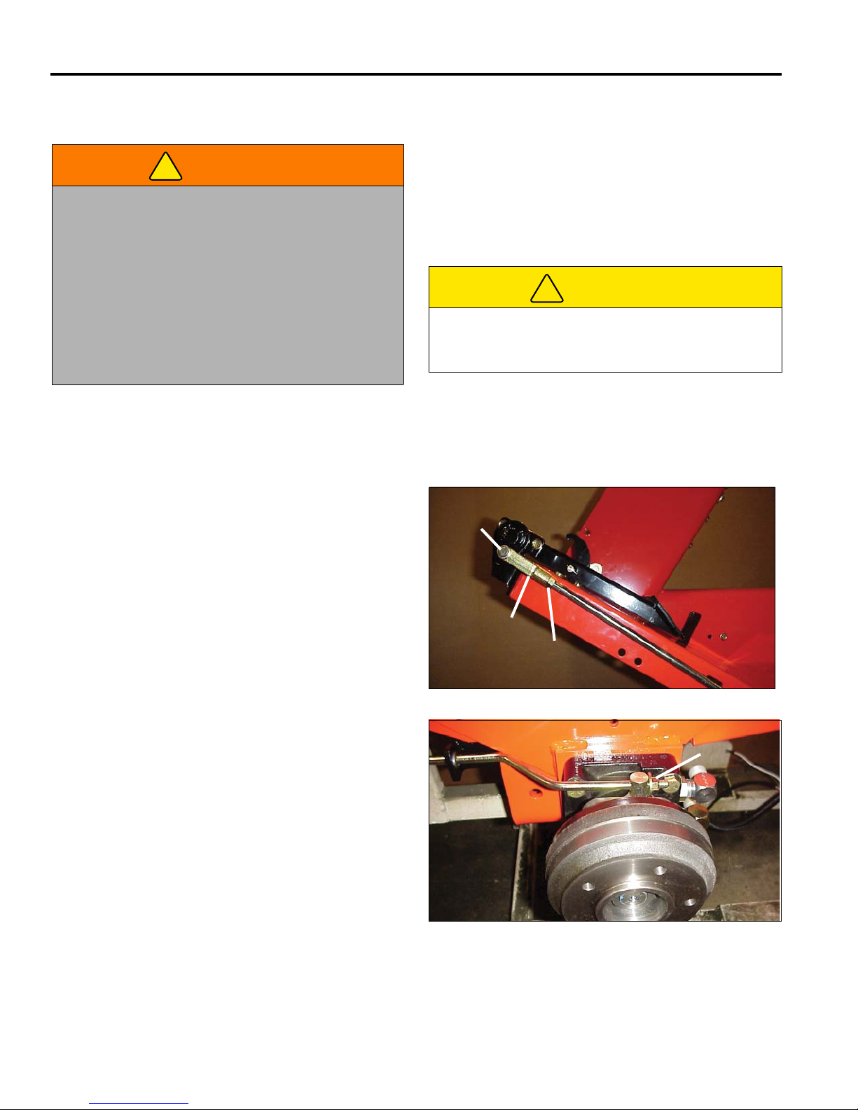
10 ADJUSTMENTS
!
!
A
B
C
D
10 ADJUSTMENTS
10.1 GENERAL ________________________________________________________________
adjustment cannot be made, contact an authorized
WARNING
To prevent injury, lower implements to the ground,
disengage all drives, engage parking brake, stop
engine, and remove key from ignition switch before
making any adjustments or performing maintenance.
Make sure the mower is parked on a solid and level
surface. Never work on a mower that is supported
only by the jack. Always use jack stands.
If only the front or rear of the mower is raised, place
chocks in front of and behind the wheels that are not
raised.
1. Adjustments and maintenance should always be
performed by a qualified technician. If proper
10.2 PARKING BRAKE _________________________________________________________
Jacobsen Dealer.
2. Replace, do not adjust, worn or damaged
components.
3. Long hair, jewelry, or loose fitting clothing may get
tangled in moving parts.
CAUTION
Be careful to prevent entrapment of the hands and
fingers between moving and fixed components of the
machine.
4. Do not change governor settings or overspeed the
engine.
If optional turn assist brakes are installed, slide the lock
pin toward the rear and to the left to lock the pedals
together.
NOTE: The brakes installed on the mower are self
adjusting and should not require adjustment under
normal operating conditions. If linings or brake drums
appear worn or damaged, have them replaced
immediately by an experienced service technician.
1. For maximum braking power, a force of 135 lbs. (61
kg) is required to engage the parking brake.
2. Adjust brake rods on the right and left hand sides so
they both begin brake engagement at the same
time. If adjustment is needed, loosen the lock nut
(A), remove the hairpin and clevis pin (B).
3. Rotate clevis (C) as required.
4. Tighten locknut (A). Assemble clevis pin (B) and
hairpin.
5. Additional adjustment is available at the brake arm if
necessary by tightening nut (D). Front wheels must
be removed before making adjustments at brake
arm.
Figure 10A
39
Figure 10B
Page 41
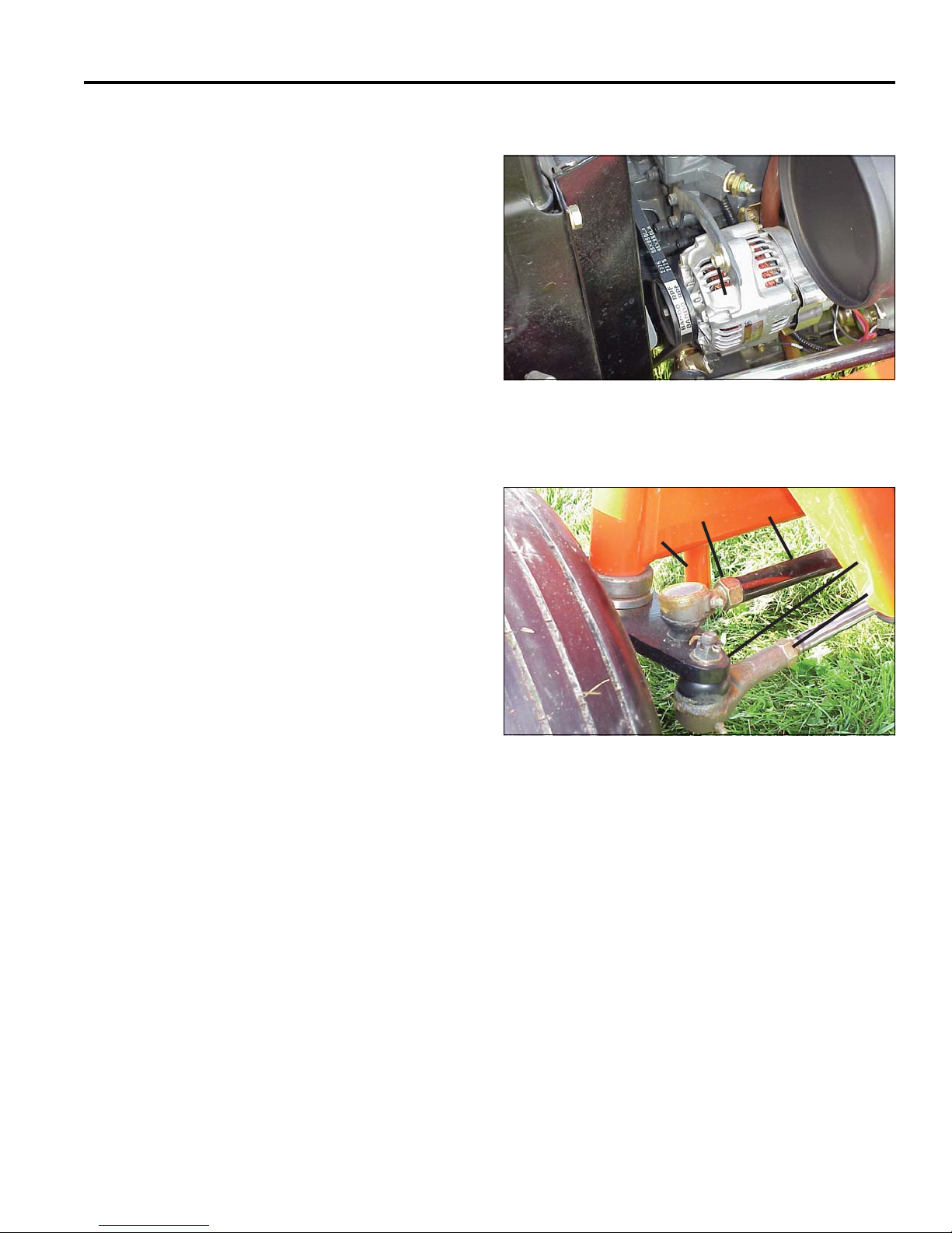
ADJUSTMENTS 10
E
F
J
G
K
H
10.3 ALTERNATOR BELT _______________________________________________________
Depress the belt at the center between the crankshaft
and alternator pulleys with a force of 11 lbs. (5 kg). The
belt should deflect approximately 0.2 in. (5 mm).
1. Loosen the pivot bolt at the base of the alternator.
2. Loosen the top bolt (E) and rotate the alternator
along the guide to increase or decrease the belt
tension.
3. While holding the alternator at this location, tighten
bolt (E).
4. Tighten the pivot bolt.
5. Verify belt tension and repeat adjustment if required.
10.4 REAR WHEEL ADJUSTMENTS_______________________________________________
To adjust wheel toe-in:
Figure 10C
The rear wheels should be 1/8 in. (3.2 mm) closer
together at the front than at the back of the wheels.
1. Loosen locknuts (F) at each ball joint near the rear
wheels.
2. Rotate tie rod (G) until the wheel is correctly
positioned.
3. Tighten locknuts (F).
To adjust steering shaft:
Loosen nut (H) and rotate steering shaft in cylinder to
provide full steering right and left. Side of arm (J) should
contact pin (K). Check both sides.
Figure 10D
40
Page 42
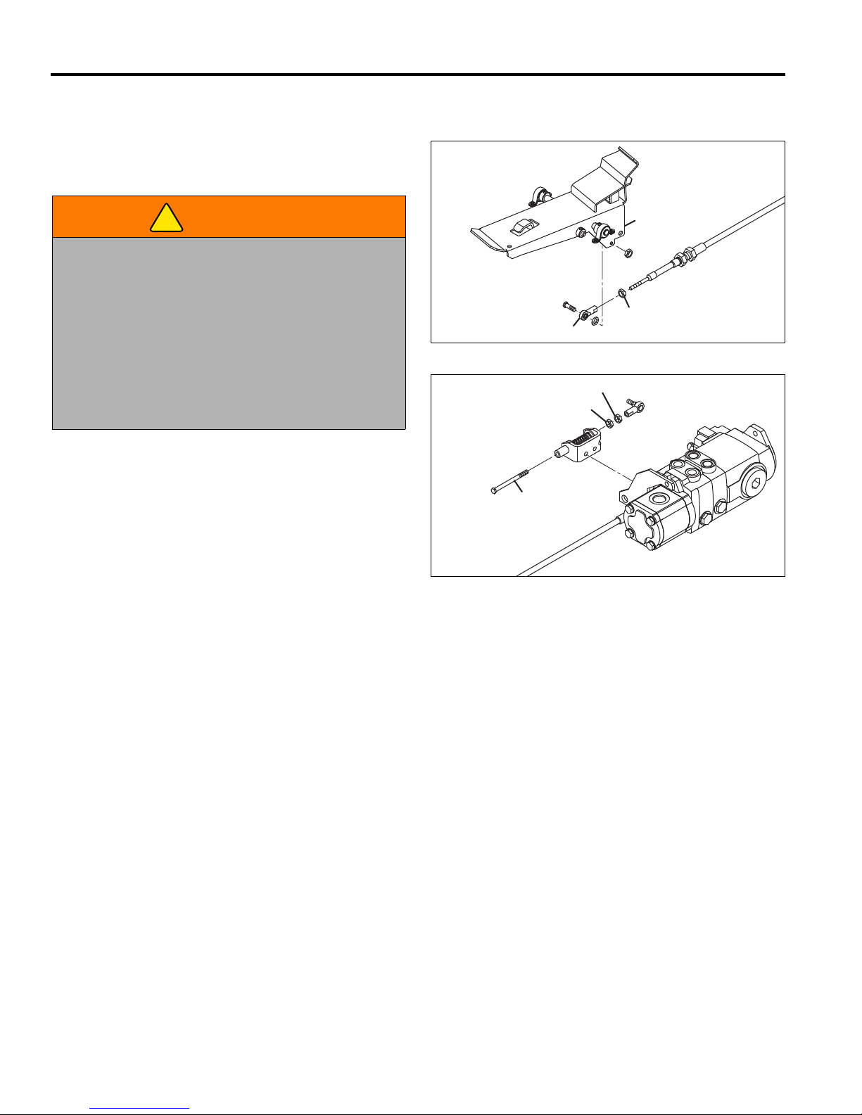
10 ADJUSTMENTS
!
L
M
S
P
R
N
10.5 TRACTION PEDAL _________________________________________________________
NOTE: Stop engine between each step.
1. Lift both right side wheels off the ground.
WARNING
Make sure the mower is parked on a solid and level
surface. Never work on a mower that is supported
only by the jack. Always use jack stands.
If only the front or rear of the mower is raised, place
chocks in front of and behind the wheels that are not
raised.
Exhaust fumes contain carbon monoxide that is toxic
and can be fatal when inhaled.
NEVER operate an engine without proper ventilation.
2. Remove ball joint (L) from bracket (M) and let it
hang.
Figure 10E
3. Start the engine and check if wheels turn. If wheels
do not turn, proceed with step 4. If wheels do turn,
adjust hydro:
a. Loosen ball joint jam nut (N).
b. Start the engine and adjust bolt (P) until the
wheels stop turning.
c. Lightly push and pull on bolt (P) to check for play
in spring. Adjust locknut (R) if necessary, to
remove play in spring. Repeat step b if required.
d. Tighten jam nut (N).
e. Stop the engine.
4. Verify the traction pedal is in neutral and neutral
latch is up and prevents pedal movement. If
required, loosen jam nut (S) and adjust ball joint (L)
until hole in ball joint aligns with hole in bracket (M).
Assemble ball joint to bracket.
5. Start engine and check for tire movement. If tires
still turn repeat adjustment.
6. Tighten all nuts that were loosened for adjustment.
Figure 10F
41
Page 43
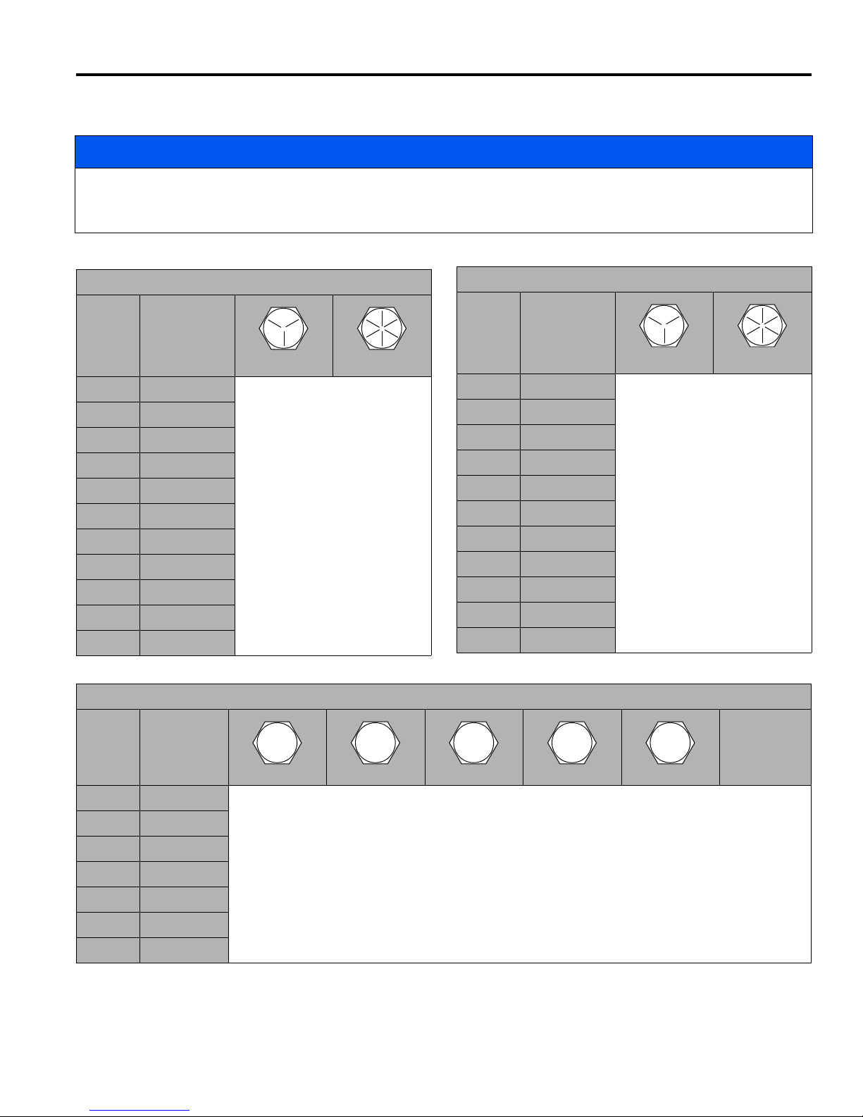
ADJUSTMENTS 10
4.8
5.8
8.8
10.9
12.9
10.6 TORQUE SPECIFICATION ___________________________________________________
NOTICE
All torque values included in these charts are approximate and are for reference only. Use of these torque values is
at your sole risk. Jacobsen is not responsible for any loss, claim, or damage arising from the use of these charts.
Extreme caution should always be used when using any torque value.
Jacobsen uses Grade 5 bolts as standard, unless otherwise noted.
AMERICAN NATIONAL STANDARD FASTENERS
SIZE UNITS
GRADE 5 GRADE 8
#6-32 in-lbs (Nm) 20 (2.3) –
#8-32 in-lbs (Nm) 24 (2.7) 30 (3.4)
#10-24 in-lbs (Nm) 35 (4.0) 45 (5.1)
#10-32 in-lbs (Nm) 40 (4.5) 50 (5.7)
#12-24 in-lbs (Nm) 50 (5.7) 65 (7.3)
1/4-20 in-lbs (Nm) 95 (10.7) 125 (14.1)
1/4-28 in-lbs (Nm) 95 (10.7) 150 (17.0)
5/16-18 in-lbs (Nm) 200 (22.6) 270 (30.5)
5/16-24 in-lbs (Nm) 240 (27.1) 300 (33.9)
3/8-16 ft-lbs (Nm) 30 (40.7) 40 (54.2)
3/8-24 ft-lbs (Nm) 35 (47.5) 45 (61.0)
AMERICAN NATIONAL STANDARD FASTENERS
SIZE UNITS
GRADE 5 GRADE 8
7/16-14 ft-lbs (Nm) 50 (67.8) 65 (88.1)
7/16-20 ft-lbs (Nm) 55 (74.6) 70 (94.9)
1/2-13 ft-lbs (Nm) 75 (101.7) 100 (135.6)
1/2-20 ft-lbs (Nm) 85 (115.3) 110 (149.2)
9/16-12 ft-lbs (Nm) 105 (142.4) 135 (183.1)
9/16-18 ft-lbs (Nm) 115 (155.9) 150 (203.4)
5/8-11 ft-lbs (Nm) 150 (203.4) 195 (264.4)
5/8-18 ft-lbs (Nm) 160 (217.0) 210 (284.8)
3/4-10 ft-lbs (Nm) 170 (230.5) 220 (298.3)
3/4-16 ft-lbs (Nm) 175 (237.3) 225 (305.1)
7/8-14 ft-lbs (Nm) 300 (406.8) 400 (542.4)
METRIC FASTENERS
SIZE UNITS Non Critical
M4 Nm (in-lbs) 1.2 (11) 1.7 (15) 2.9 (26) 4.1 (36) 5.0 (44) 2.0 (18)
M5 Nm (in-lbs) 2.5 (22) 3.2 (28) 5.8 (51) 8.1 (72) 9.7 (86) 4.0 (35)
M6 Nm (in-lbs) 4.3 (38) 5.7 (50) 9.9 (88) 14.0 (124) 16.5 (146) 6.8 (60)
M8 Nm (in-lbs) 10.5 (93) 13.6 (120) 24.4 (216) 33.9 (300) 40.7 (360) 17.0 (150)
M10 Nm (ft-lbs) 21.7 (16) 27.1 (20) 47.5 (35) 66.4 (49) 81.4 (60) 33.9 (25)
M12 Nm (ft-lbs) 36.6 (27) 47.5 (35) 82.7 (61) 116.6 (86) 139.7 (103) 61.0 (45)
M14 Nm (ft-lbs) 58.3 (43) 76.4 (55) 131.5 (97) 184.4 (136) 219.7 (162) 94.9 (70)
Fasteners
into
Aluminum
42
Page 44

11 PROBLEM SOLVING
11 PROBLEM SOLVING
11.1 GENERAL ________________________________________________________________
The troubleshooting chart below lists basic problems that may occur during start-up and operation. For more detailed
information regarding the hydraulic and electrical systems contact your area Jacobsen Dealer.
Symptoms Possible Causes Action
Engine will not start. 1. Traction pedal not in neutral or
Interlock switch on.
2. Battery low on charge or
defective.
3. Fuel tank empty or dirty. 3. Fill with fresh fuel. Change fuel filter. Bleed fuel
4. Fuse blown. 4. Replace fuse.
Engine hard to start
or runs poorly.
1. Fuel level low, fuel or fuel filter
dirty.
2. Air cleaner dirty. 2. Inspect and replace air filter.
3. Injectors, fuel pump. 3. Consult engine manual.
4. Engine problem. 4. Consult engine manual.
Engine stops. 1. Fuel tank empty. 1. Fill with fresh fuel and bleed fuel lines.
2. Interlocks not set before
leaving operator’s seat.
Engine overheating. 1. Coolant level low. 1. Inspect and add coolant.
2. Air intake restricted. 2. Clean cooling air intake.
3. Water pump belt broken or
loose.
4. Engine overload. 4. Reduce forward speed.
Battery not holding
charge.
1. Loose or corroded battery
terminals.
2. Low electrolyte. 2. Refill to correct level.
3. Alternator belt loose or broken. 3. Tighten or replace belt.
4. Charging system defective. 4. See engine manual.
Mowers do not cut or
cut unevenly.
1. Cutting units not fully lowered. 1. Lower cutting units to ground.
2. Engine speed too low. 2. Check engine speed. Run engine at full throttle.
3. Low hydraulic oil. 3. Check reservoir level and fill if needed.
Mower does not react
to traction pedal.
1. Parking brake engaged. 1. Disengage parking brake.
2. Tow Valve Open. 2. Close Tow Valve.
3. Low hydraulic oil. 3. Check reservoir level and fill if needed.
Implement does not
1. Low hydraulic oil. 1. Check reservoir level and fill as needed.
raise or lower.
Gauges/Indicator not
operating.
1. Fuse blown. 1. Replace fuse, check bulbs.
2. Loose wiring. 2. Check electrical connections.
1. Check Interlock System and start-up procedure.
2. Inspect condition of battery and battery
connections.
lines.
1. Fill with fresh fuel. Change fuel filter. Bleed fuel
lines.
2. Engage parking brake, set PTO switch to OFF
and traction pedal in neutral before leaving seat.
3. Tighten or replace belt.
1. Inspect and clean terminals.
43
Page 45
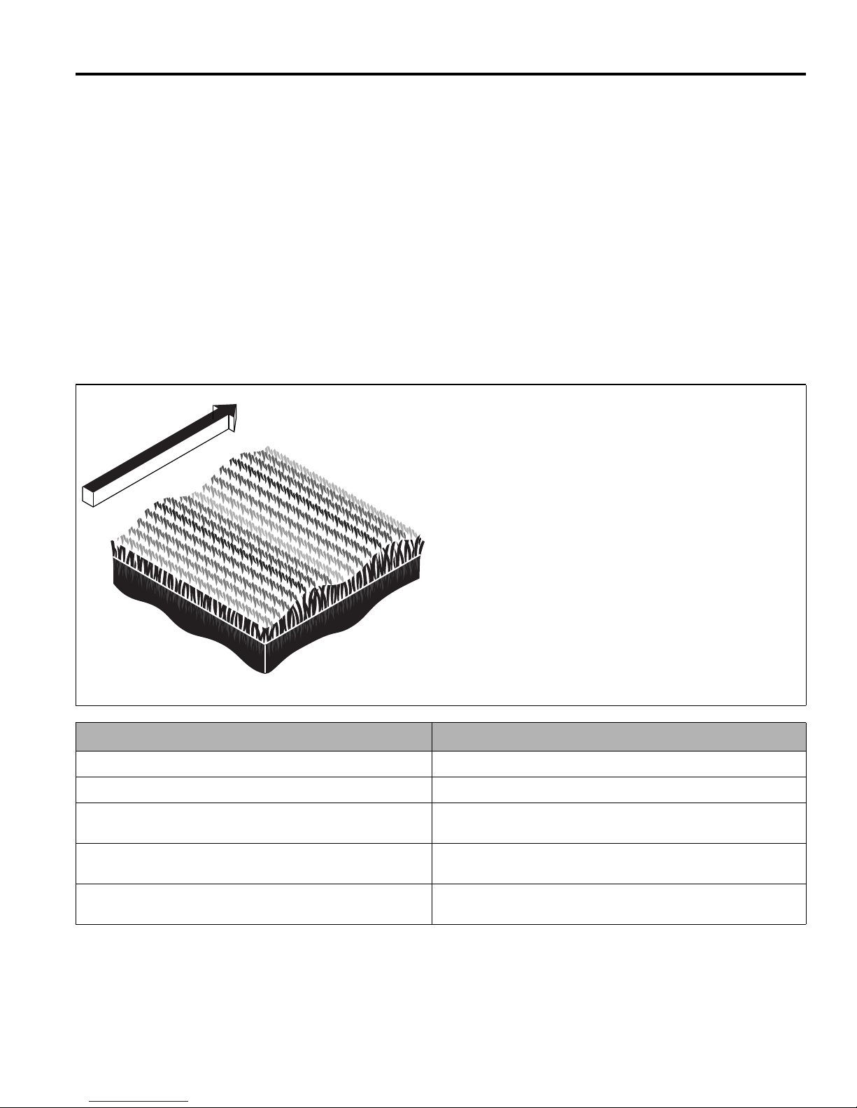
QUALITY OF CUT 12
TN0159
12 QUALITY OF CUT
12.1 QUALITY OF CUT TROUBLESHOOTING _______________________________________
It is recommended that a “test cut” be performed to
evaluate the mower’s performance before beginning
repairs.
An area should be available where “test cuts” can be
made. This area should provide known and consistent
turf conditions to allow accurate evaluation of the
mower’s performance.
Another “test cut” should be performed after the
completion of the repairs and/or adjustments to verify the
Before performing a “test cut” to diagnose cut
appearance and mower performance, the following items
should be verified to ensure an accurate “test cut.”
1. Mowing (Ground) Speed
2. Blade Sharpness
3. Height-of-Cut (HOC)
4. Roller and Roller Bearing Condition
5. Blade Speed
mower’s performance.
12.2 WASHBOARDING__________________________________________________________
Washboarding is a cyclical pattern of varying cutting
heights, resulting in a wave-like cut appearance. In most
cases, the wave tip-to-tip distance is approximately
6—8 in. (15—20 cm). Color variation (light-to-dark) may
also be noticed.
This condition is usually caused by a rocking motion in
the cutting unit(s). This condition is found mostly on
mowers with multiple (suspended) cutting units.
Washboarding may also be caused by variations in the
turf.
NOTE: Arrow indicates direction of travel.
Probable Cause Remedy
Mowing (ground) speed is too fast. Reduce mowing (ground) speed.
Mowing in the same direction. Change mowing direction regularly.
Cutting units have too much or too little weight on them. Use weight transfer switch to transfer weight on or off cutting units.
(Refer to Parts & Maintenance Manual.)
Insufficient engine speed, not set to specification. Check/adjust engine speed. (Refer to Parts & Maintenance
Manual.)
Hydraulic system and/or rotary drive motor performance is
reduced.
Check hydraulic system performance (pump output, motor
operation, valve operation, relief valve settings, etc.).
44
Page 46
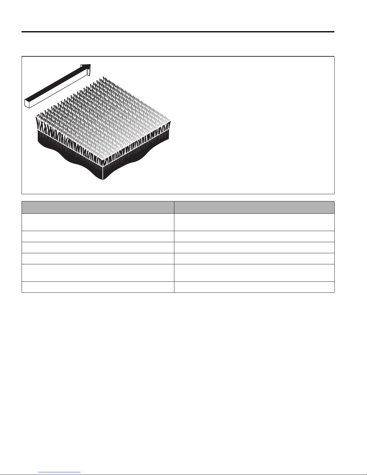
12 QUALITY OF CUT
TN0221
12.3 STEP CUTTING ___________________________________________________________
Step cutting occurs when grass is cut taller on one side of
a cutting unit than the other or on one side of mower to
the other. This is usually caused by mechanical wear or
an incorrect roller or deck caster adjustment.
NOTE: Arrow indicates direction of travel.
Probable Cause Remedy
HOC (height-of-cut) settings are different from one side of a
cutting unit to the other or from one cutting unit to another.
Worn deck caster wheel bearings. Check/replace deck caster wheel bearings.
Cutting unit movement is restricted. Check/remove cutting unit movement restriction.
Variations in turf density Change mowing direction.
Machine ride height is uneven side to side. Check/adjust proper tire inflation pressure. (Refer to Parts &
Cutting unit height is uneven side to side. Check/adjust for even mower weight distribution.
Check HOC adjustment of cutting units. (Refer to Parts &
Maintenance Manual.)
Maintenance Manual.)
45
Page 47
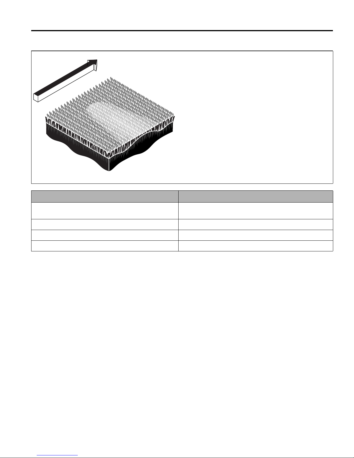
QUALITY OF CUT 12
TN0222
12.4 SCALPING _______________________________________________________________
Scalping is a condition in which areas of grass are cut
noticeably shorter than the surrounding areas, resulting in
a light green or even brown patch. This is usually caused
by an excessively low height-of-cut setting and/or uneven
turf.
NOTE: Arrow indicates direction of travel.
Probable Cause Remedy
HOC (height-of-cut) settings are lower than normal. Check and adjust the HOC settings. (Refer to Parts & Maintenance
Manual.)
Turf too uneven for the mower to follow. Change mowing direction.
Cutting too much grass at one time. Mow more often.
Mowing (ground) speed is too fast. Reduce mowing (ground) speed.
46
Page 48
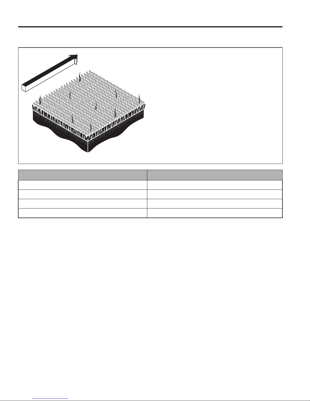
12 QUALITY OF CUT
TN0223
12.5 STRAGGLERS ____________________________________________________________
Stragglers are scattered blades of uncut or poorly cut
grass.
NOTE: Arrow indicates direction of travel.
Probable Cause Remedy
Dull cutting blade(s). Sharpen blade(s). (Refer to Parts & Maintenance Manual.)
Mowing (ground) speed is too fast. Reduce mowing (ground) speed.
Grass is too tall. Mow more often.
Mowing in the same direction. Change mowing direction regularly.
47
Page 49
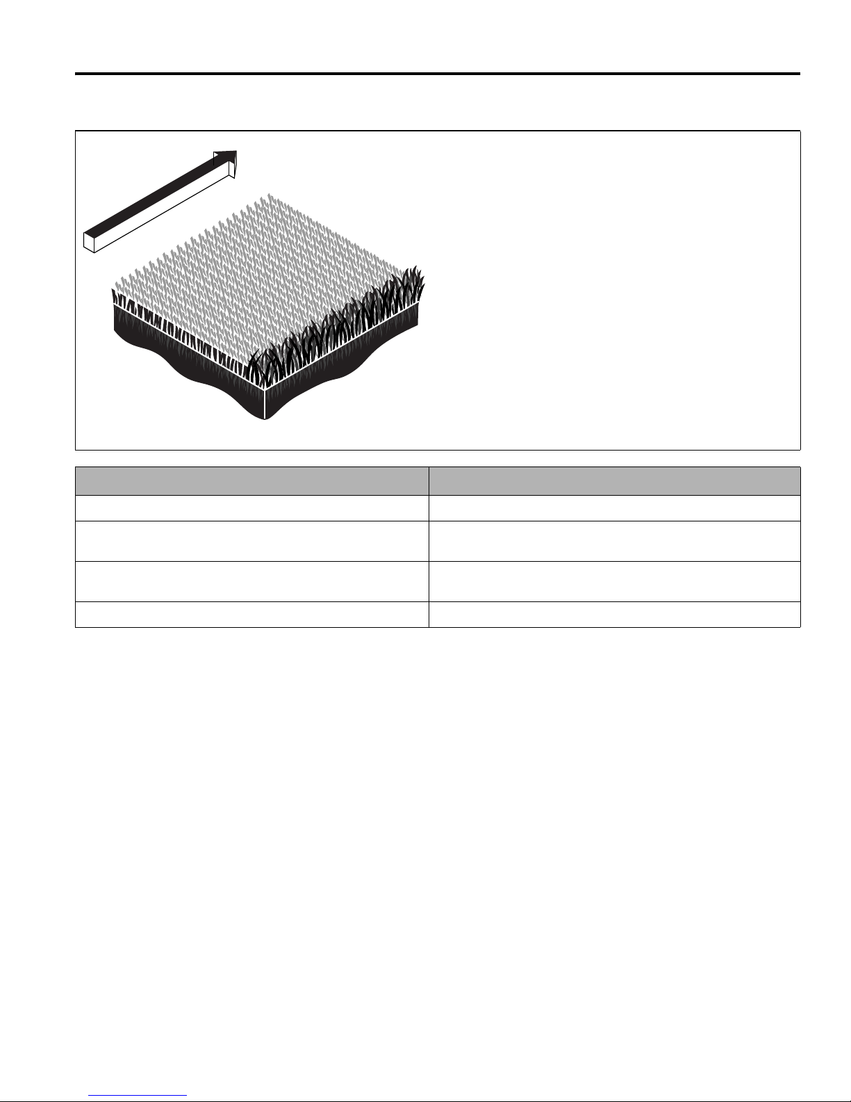
QUALITY OF CUT 12
TN0224
12.6 STREAKS ________________________________________________________________
A streak is a line of uncut grass. This is usually caused by
a damaged blade.
NOTE: Arrow indicates direction of travel.
Probable Cause Remedy
Damaged blade(s). Replace blade(s).
Turning too aggressively. Cutting units don’t overlap during turns
or on side hills.
Tire mats down grass before it is cut. Check/adjust tire inflation pressure. (Refer to Parts & Maintenance
Wet grass is matted down before it is cut. Cut when grass is dry.
Turn less aggressively to allow cutting units to overlap. Change
mowing direction or pattern on side hills.
Manual.)
48
Page 50
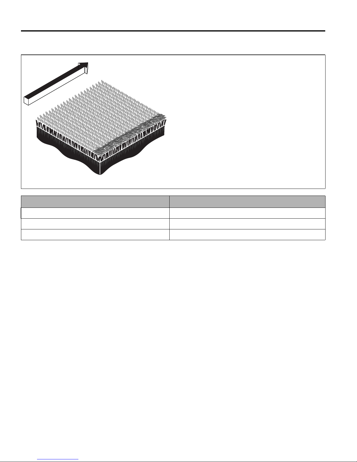
12 QUALITY OF CUT
TN0225
12.7 WINDROWING ____________________________________________________________
Windrowing is the deposit of clippings concentrated at
one end of cutting unit(s) or between cutting units,
forming line(s) in the direction of travel.
NOTE: Arrow indicates direction of travel.
Probable Cause Remedy
Grass is too tall. Mow more often.
Mowing while grass is wet. Mow when grass is dry.
Grass collecting on mower or cutting unit frame. Clear cutting unit(s) discharge deflector.
49
Page 51
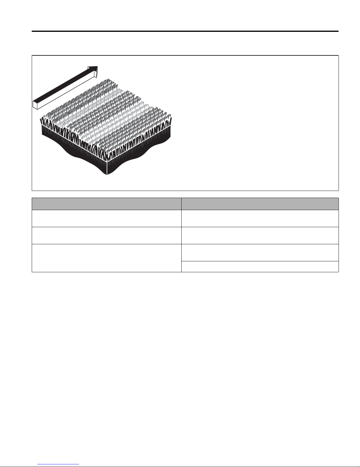
QUALITY OF CUT 12
TN1278
12.8 MISMATCHED CUTTING UNITS ______________________________________________
Mismatched cutting units is a pattern of varying cutting
heights, resulting in a stepped cut appearance, usually
due to mismatched HOC (height-of-cut) adjustment from
one cutting unit to another.
NOTE: Arrow indicates direction of travel.
Probable Cause Remedy
HOC inconsistent from one cutting unit to another. Check/adjust HOC on cutting units to same height. (Refer to Parts &
Maintenance Manual.)
Difference in rotary cutting unit speeds. Check operation of rotary cutting motor(s) and repair/replace as
necessary.
Difference in mower ride height side to side. Check/adjust tire inflation pressure. (Refer to Parts & Maintenance
Manual.)
Check/adjust for even mower weight distribution.
50
Page 52

Jacobsen, A Textron Company
11108 Quality Drive, Charlotte, NC 28273
www.Jacobsen.com
800-848-1636
When Performance Matters.
™
Equipment from Jacobsen is built to exacting
standards ensured by ISO 9001 and ISO 14001
registration at all of our manufacturing locations.
A worldwide dealer network and factory trained
technicians backed by Genuine Jacobsen Parts
provide reliable, high-quality product support.
 Loading...