

Page 1
When Performance Matters.
™
4273092-IT-RevA
IT
Italy
Safety, Operation and Maintenance Manual
Manuale di sicurezza, uso e manutenzione
AR522™
68131 – AR522-T4I, Kubota® V2403-M-DI, 4WD with ROPS
68131 – AR522-T4I, Kubota® V2403-M-DI, 4WD con ROPS
WARNING
WARNING: If incorrectly used this machine can cause severe
injury. Those who use and maintain this machine should be
trained in its proper use, warned of its dangers and should
read the entire manual before attempting to set up, operate,
adjust or service the machine.
AVVERTENZA
AVVERTENZA: Questa macchina può causare gravi infortuni
se viene utilizzata in modo errato. Prima di accingersi ad
approntare, usare, mettere a punto o eseguire la
manutenzione di questa macchina, coloro che la utilizzano ed
i responsabili della manutenzione devono essere addestrati
all’impiego della macchina, devono essere informati dei
pericoli, e devono leggere l’intero manuale.
Page 2
CHARLOTTE, NC
YEAR OF
PRODUCTION:
MADE IN U.S.A.
®
A Textron Company
FOREWORD
This manual contains safety and operating instructions
for your new Jacobsen machine. This manual should be
stored with the equipment for refere nc e du rin g op e ra tio n.
Before you operate your machine, you and each op erator
you employ should read the manual carefully in its
entirety. By following the safety, operating, and
maintenance instructions, you will prolong the life of your
equipment, and maintain its maximum efficiency.
If additional information is needed, contact your
Jacobsen Dealer.
The serial plate is located on the left rear frame rail.
Jacobsen recommends you record these numbers below
for easy reference.
© 2013, Jacobsen, A Textron Company/Textron Innovations Inc.
“All rights reserved, including the right to reproduce this material
or portions thereof in any form.”
2
Proposition 65 Warning
This product contains or emits
chemicals known to the State of
California to cause cancer and birth
defects or other reproductive harm.
LITHO IN U.S.A. 9-2014
Page 3

CONTENTS
CONTENTS
CONTENTS
SAFETY
1.1How to Operate Safely . . . . . . . . . . . . . . . . . . . . 4
1.2 Important Safety Notes . . . . . . . . . . . . . . . . . 7
SPECIFICATIONS
2.1 Product Identification . . . . . . . . . . . . . . . . . . 8
2.2 V2403-M-DI Engine . . . . . . . . . . . . . . . . . . . 8
2.3 Mower . . . . . . . . . . . . . . . . . . . . . . . . . . . . . . 8
2.4 Weights and Dimensions . . . . . . . . . . . . . . . 8
2.5 Cutting Units . . . . . . . . . . . . . . . . . . . . . . . . . 9
2.6 Accessories . . . . . . . . . . . . . . . . . . . . . . . . . 9
2.7 Support Literature . . . . . . . . . . . . . . . . . . . . . 9
2.8 Declaration of Conformity . . . . . . . . . . . . . . 10
2.9 Vibration Level . . . . . . . . . . . . . . . . . . . . . . 13
DECALS
CONTROLS
4.1 Icons . . . . . . . . . . . . . . . . . . . . . . . . . . . . . . 18
4.2 Controls . . . . . . . . . . . . . . . . . . . . . . . . . . . . 19
4.3 Control Panel . . . . . . . . . . . . . . . . . . . . . . . 21
4.4 Operator Alerts . . . . . . . . . . . . . . . . . . . . . . 22
OPERATION
5.1 Daily Inspection . . . . . . . . . . . . . . . . . . . . . 23
5.2 Interlock System . . . . . . . . . . . . . . . . . . . . . 23
5.3 Operating Procedures . . . . . . . . . . . . . . . . . 24
5.4 Starting . . . . . . . . . . . . . . . . . . . . . . . . . . . . 25
5.5 Stopping / Parking . . . . . . . . . . . . . . . . . . . 25
5.6 To Drive / Transport . . . . . . . . . . . . . . . . . . 26
5.7 Mowing . . . . . . . . . . . . . . . . . . . . . . . . . . . . 26
5.8 Mowing Speed . . . . . . . . . . . . . . . . . . . . . . 26
5.9 Hillside Operation . . . . . . . . . . . . . . . . . . . . 27
5.10 Towing / Trailering . . . . . . . . . . . . . . . . . . . 29
5.11 Daily Maintenance . . . . . . . . . . . . . . . . . . . 30
7.14 Electrical System . . . . . . . . . . . . . . . . . . . . 37
7.15 Radiator . . . . . . . . . . . . . . . . . . . . . . . . . . . 38
7.16 Roll Over Protective Structure (ROPS) . . . . 38
7.17 Tires . . . . . . . . . . . . . . . . . . . . . . . . . . . . . . 38
7.18 Wheel Mounting Procedure . . . . . . . . . . . . 39
7.19 Inspecting Blades . . . . . . . . . . . . . . . . . . . . 39
7.20 Sharpening Blades . . . . . . . . . . . . . . . . . . . 40
7.21 Care and Cleaning . . . . . . . . . . . . . . . . . . . 40
7.22 Storage . . . . . . . . . . . . . . . . . . . . . . . . . . . . 41
ADJUSTMENTS
8.1 General . . . . . . . . . . . . . . . . . . . . . . . . . . . . 42
8.2 Mow Speed . . . . . . . . . . . . . . . . . . . . . . . . . 42
8.3 Belt . . . . . . . . . . . . . . . . . . . . . . . . . . . . . . . 42
8.4 Neutral Adjustment . . . . . . . . . . . . . . . . . . . 43
8.5 Forward / Reverse Speed . . . . . . . . . . . . . . 43
8.6 Steering Toe-In . . . . . . . . . . . . . . . . . . . . . . 44
8.7 Traction Control System Calibration . . . . . . 44
8.8 Cutting Height . . . . . . . . . . . . . . . . . . . . . . . 45
8.9 Torque Specification . . . . . . . . . . . . . . . . . . 46
PROBLEM SOLVING
9.1 General . . . . . . . . . . . . . . . . . . . . . . . . . . . . 47
9.2 Controller Lamps . . . . . . . . . . . . . . . . . . . . . 48
9.3 Electrical Circuits . . . . . . . . . . . . . . . . . . . . 49
QUALITY OF CUT
10.1 Quality of Cut Troubleshooting . . . . . . . . . . 50
10.2 Washboarding . . . . . . . . . . . . . . . . . . . . . . . 50
10.3 Step Cutting . . . . . . . . . . . . . . . . . . . . . . . . 51
10.4 Scalping. . . . . . . . . . . . . . . . . . . . . . . . . . . 52
10.5 Stragglers . . . . . . . . . . . . . . . . . . . . . . . . . . 53
10.6 Streaks . . . . . . . . . . . . . . . . . . . . . . . . . . . . 54
10.7 Windrowing . . . . . . . . . . . . . . . . . . . . . . . . . 55
10.8 Mismatched Cutting Units . . . . . . . . . . . . . . 56
NOTES
MAINTENANCE & LUBRICATION CHARTS
6.1 General . . . . . . . . . . . . . . . . . . . . . . . . . . . . 31
6.2 Maintenance Chart . . . . . . . . . . . . . . . . . . . 31
6.3 Lubrication Chart . . . . . . . . . . . . . . . . . . . . 32
MAINTENANCE
7.1 General . . . . . . . . . . . . . . . . . . . . . . . . . . . . 33
7.2 Engine . . . . . . . . . . . . . . . . . . . . . . . . . . . . . 33
7.3 Engine Oil . . . . . . . . . . . . . . . . . . . . . . . . . . 33
7.4 Air Filter . . . . . . . . . . . . . . . . . . . . . . . . . . . 34
7.5 Fuel . . . . . . . . . . . . . . . . . . . . . . . . . . . . . . . 34
7.6 Fuel System . . . . . . . . . . . . . . . . . . . . . . . . 34
7.7 Battery . . . . . . . . . . . . . . . . . . . . . . . . . . . . 35
7.8 Jump Starting . . . . . . . . . . . . . . . . . . . . . . . 35
7.9 Charging Battery . . . . . . . . . . . . . . . . . . . . . 35
7.10 Muffler and Exhaust . . . . . . . . . . . . . . . . . . 36
7.11 Hydraulic Hoses . . . . . . . . . . . . . . . . . . . . . 36
7.12 Hydraulic Oil . . . . . . . . . . . . . . . . . . . . . . . . 36
7.13 Hydraulic Filter . . . . . . . . . . . . . . . . . . . . . . 37
3
Page 4

1 SAFETY
!
1 SAFETY
1.1 HOW TO OPERATE SAFELY
WARNING
EQUIPMENT OPERATED INCORRECTLY OR WITHOUT TRAINING CAN BE DANGEROUS.
Know the location and correct operation of controls. Operators without experience mus t receive instruction from
another person that knows the correct operation of the equipment before you operate the mowe r.
Only use parts, accessories and attachments approved by Jacobsen.
SAFE OPERATION
a Read the Operator’s Manual and other training
material. If the operator or technician can not read
this manual, the owner is responsible to describe
this material to the operators and technicians.
Manuals in additional languages may be available
on the Jacobsen or RansomesJacobsen website.
a Read all of the instructions for this mower carefully.
Know the controls and the correct operation of the
equipment.
b Children or persons who do not understand these
instructions must not use the mower. The local
regulations can limit the age of the operator.
c Never use a mower near persons, including
children or animals.
d Remember that the operator or owner is
responsible for accidents or hazards that occur to
other persons or their property.
e Never carry passengers.
f Never allow persons to operate or service the
mower or its attachments without correct
instructions.
g Do not operate equipment while tired, sick or after
you use alcohol or drugs.
PREPARATION
a When you operate the mower, wear correct
clothing, slip resistant work shoes or boots, work
gloves, hard hat, safety glasses and hearing
protection. Long hair, loose clothing or jewelry can
be caught in moving parts.
b Do not operate the equipment with the Interlock
System disconnected or the system does not
operate correctly. Do not disconnect or prevent the
operation of any switch.
c Never operate equipment that is not in correct
order or without decals, guards, shields, deflectors
or other protective devices fastened. DO NOT
operate the cutting unit without the discharge chute
or mulching plate installed.
d Inspect the mower before you operate the mower.
Check the tire pressure, engine oil level, the
radiator coolant level and the air cleaner indicator.
Fuel is flammable. Use caution when you add the
fuel to the mower.
e Operate the mower in daylight or in good artificial
light. Use caution when you operate the mower
during bad weather. Never operate the mower with
lightning in the area.
f Inspect the area to select the accessories and
attachments that are needed to correctly and safely
do the job. Only use parts, accessories and
attachments approved by Jacobsen.
g Be careful of holes in the terrain and other hazards
that are not visible.
h Inspect the area where the equipment is operated.
Remove all objects you can find before you
operate. Be careful of obstructions above the
ground (low tree limbs, electrical wires) and also
underground obstacles (sprinklers, pipes, tree
roots). Enter a new area carefully. Look for
possible hazards.
i Inspect the cutting system before you start the
mower. Make sure the blades are free to rotate.
When you rotate one blade, other blades can
rotate.
OPERATION
a Never operate the engine without enough
ventilation or in an enclosed area. The carbon
monoxide in the exhaust fumes can increase to
dangerous levels.
b Never carry passengers. Keep other persons or
animals away from the mower .
c Disengage all drives and engage the parking brake
before you start the engine. Only start the engine
with the operator in the seat. Never start the engine
with persons near the mower.
4
Page 5

SAFETY 1
d Keep your legs, arms and body inside the operator
compartment while the mower is in operation.
Keep your hands and feet away from the cutting
units.
e Do not use on the slopes greater than the safe
slope limit for the equipment.
f To guard against over turning or loss of control:
– Operate the mower up and down on the face of
slopes (vertically), but not across the face
(horizontally).
– Do not start or stop suddenly on slopes.
– Decrease the speed when you operate on slopes
or when you must turn. Use caution when you
change direction. Turf condition can change the
mower stability.
– Use caution when you operate the mower near
drop-offs, ditches or embankments.
– Be careful of holes in the terrain and other hazards
that are not visible.
g When you drive in the reverse direction, look
behind you and down to make sure the path is
clear. Do not operate the cutting units when you
drive in the reverse direction.
h Use caution when you go near corners, trees or
other objects that can prevent a clear view.
i Equipment must meet the current regulations to be
driven on the public roads.
j Before you move across or operate on the paths or
roads, turn off the PTO switch, lift the mowers and
travel at decreased speed. Look for traffic.
k Stop the blades when the mower is on any surface
that is not grass.
l Do not release the cut grass in the direction of
persons or allow persons near the mower while in
operation.
m Do not operate the mower with damaged guards or
without safety devices in position.
n Do not change the engine governor setting or over-
speed the engine. Never change or tamper with
adjusters that are closed with a seal for the engine
speed control.
o Before you leave the operator compartment, for
any reason:
– Disengage all the drives and lower attachments to
the ground.
– Engage the parking brake.
– Stop the engine and remove the key.
p When you hit an object or mower starts to cause
the vibration that is not normal, inspect the mower
for damage and make repairs.
q Decrease the throttle setting before you stop the
engine.
r Do not use this equipment for uses that the mower
was not made for.
ROPS
a The ROPS is a safety device. Keep the ROPS in
the vertical and locked position. Always use the
seat belt when you operate the mower. Make sure
the seat belt can be released quickly in an
emergency.
b Only operate the mower with the ROPS in the
folded position on flat and level surfaces when
necessary. Do not operate the mower with the
ROPS in the folded position on slopes, near sharp
edges or near water. There is no roll over
protection with the ROPS in the folded position.
c Check for clearance before you drive below
objects. Do not contact tree branches, electrical
wires or other objects with the ROPS.
d Do not use the seat belt with the ROPS in the
folded position.
e Inspect the ROPS for damage. Keep the ROPS
hardware fastened.
f Do not weld, drill, change or bend the ROPS.
Replace a damaged ROPS. Do not try to correct a
damaged ROPS.
g Do not remove the ROPS from the mower.
h Jacobsen must approve any changes to the
ROPS.
SAFE HANDLING OF FUELS
a The fuel and the fuel vapors are flammable. Use
caution when you add the fuel to the mower. The
fuel vapors can cause an explosion.
b Never use the containers that are not approved to
keep or transfer fuel.
c Never keep the mower or fuel containers near an
open flame or any device that can cause the
ignition of fuel or fuel vapors.
d Never fill the fuel containers inside a vehicle or on
a truck or trailer with a plastic liner. Always put the
fuel container on the ground away from your
vehicle before you fill the container.
5
Page 6

1 SAFETY
e Refuel the mower before you start the engine.
When the engine is in operation or while the engine
is hot, never remove the fuel cap or add fuel to the
mower.
f Refuel outdoors only and do not smoke when you
add fuel. Extinguish all types of ignition.
g The fuel nozzle must touch the rim of the fuel tank
when you add fuel to the mower. Do not use a
device to lock the fuel nozzle in the open position.
h Do not over fill the fuel tank. Leave at least 1 inch
(2.5 cm) below the filler neck.
i Always tighten the fuel tank cap and container cap
after you add fuel.
j If the fuel spills on your clothing, change your
clothing immediately.
MAINTENANCE AND STORAGE
a Before you clean, adjust or repair this equipment,
push PTO switch to the OFF position, lower the
cutting unit to the ground, engage the parking
brake, stop the engine and remove the key.
b Make sure the mower is parked on a solid and level
surface.
c Never work on a mower that is lifted only by the
jack. Always use the jack stands.
d Never allow persons to service the mower or its
attachments without correct instructions.
e When the mower is parked, put into storage or left
without an operator, lower the cutting device unless
a positive mechanical lock is used.
f When you put the mower on a trailer or put the
mower in storage, close the fuel valve. Do not keep
fuel near flames or drain the fuel inside a building.
g Disconnect the battery before you service the
mower. Always disconnect the negative battery
cable before the positive battery cable. Always
connect the positive battery cable before the
negative battery cable.
h Charge the battery in an area with good airflow.
The battery can release hydrogen gas that is
explosive. To prevent an explosion, keep any
device that can cause sparks or flames away from
the battery.
i Disconnect the battery charger from the power
supply before you connect or disconnect the
battery charger to the battery. Wear protective
clothing and use insulated tools when you service
the battery.
j Be careful and wear gloves when you check or
service the cutting unit blades. Replace any
damaged blades, do not try to correct a damaged
blade.
k Keep your hands and feet away from parts that
move. Do not adjust the mower with the engine in
operation, unless the adjustment needs the engine
in operation.
l Carefully release the pressure from components
with stored energy.
m To prevent injury from the hot, high pressure oil,
never use your hands to check for oil leaks. Use
the paper or cardboard to find leaks.
n The hydraulic fluid pressure can have enough
force to enter your skin. If hydraulic fluid has
entered your skin, a doctor must remove the
hydraulic fluid surgically within a few hours or
gangrene can occur.
o When you service the hydraulic system, make sure
the hydraulic fittings, tubes and hoses are
tightened to the correct torque. Make sure the
hydraulic system is in good condition before you
start the engine.
p Keep the mower and the engine clean.
q Allow the engine to become cool before storage
and always remove the ignition key.
r Keep all nuts, bolts and screws tight to make sure
the equipment is in safe condition.
s Replace worn or damaged parts for safety.
Replace damaged or worn decals. Only use parts,
accessories and attachments approved by
Jacobsen.
t To decrease the fire ha zard, remove mat erials that
burn from the engine, muffler, battery tray and fuel
tank area.
u Disconnect the battery and controller connectors
before you weld on this mower.
WHEN YOU PUT THE MOWER ON A
TRAILER
a Be careful when you load or unload the mower on
a trailer. Trailer must be wider than the mower and
can carry the weight of the mower.
b Use a full-width ramp to load or unload the mower
on a trailer.
c Use straps, chains, cables or ropes to fasten the
mower to the trailer. Both front and rear straps
must be sent down and toward sides of trailer.
6
d Make sure that all latches are correctly fastened.
Page 7

SAFETY 1
!
!
1.2 IMPORTANT SAFETY NOTES________________________________________________
This safety alert symbol is used to alert you to potential hazards.
DANGER - Indicates an imminently hazardous situation which, if not avoided, WILL result in death or serious injury.
WARNING - Indicates a potentially hazardous situation which, if not avoided, COULD result in death or serious
injury.
CAUTION - Indicates a potentially hazardous situation which, if not avoided, MAY result in minor or moderate injury
and property damage. It may also be used to alert against unsafe practices.
NOTICE - Indicates a potentially hazardous situation which, if not avoided, MAY result in property damage. It may
also be used to alert against unsafe practices.
For pictorial clarity, some illustrations in this manual may show shields, guards, or plates, open or removed. Under no
circumstances should this equipment be operated without these devices securely fastened in place.
WARNING
The Interlock System on this mower prevents the mower from starting unless
the brake lever is engaged, PTO switch is off and traction pedal is in neutral.
The system will stop the engine if the operator leaves the seat without
engaging the parking brake or setting the PTO switch off.
NEVER operate mower unless the Interlock System is working.
WARNING
1. Before leaving the operator’s position for any reason:
a. Return traction pedal to Neutral.
b. Disengage all drives.
c. Lower all implements to the ground.
d. Engage parking brake.
e. Stop engine and remove the ignition key.
2. Keep hands, feet, and clothing away from moving parts. Wait for all
movement to stop before you clean, adjust, or service the machine.
3. Keep the area of operation clear of all bystanders and pets.
4. Never carry passengers, unless a seat is provided for them.
5. Never operate mowing equipment without the discharge deflector securely
fastened in place.
By following all instructions in this manual, you will prolong the life of your machine and maintain its maximum
efficiency. Adjustments and maintenance should always be performed by a qualified technician.
If additional information or service is needed, contact your Authorized Jacobsen Dealer who is kept informed of the
latest methods to service this equipment and can provide prompt and efficient service.
7
Page 8

2 SPECIFICATIONS
1674 36.5 XXXX
6813101651
2 SPECIFICATIONS
2.1 PRODUCT IDENTIFICATION_________________________________________________
68131..............................AR522-T4I, 5 Gang 4WD with
®
ROPS
An identification plate, like the one shown, listing the
serial number, is attached to the frame of the mower and
is located on the operator’s right just over the rear axle.
Always provide the serial number of the unit when
ordering replacement parts or requesting service
PRODUCT OF U.S .A.
ABC
kg kW
A Textron Company
D
information.
2.2 V2403-M-DI ENGINE _______________________________________________________
11524 WILMA R BL VD,
CHA R L OT TE , NC 28273
1-800-848-1636 (US)
Make............................... Kubota
Model.............................. V2403-M-DI Diesel, 4 cycle, liquid
cooled
Horsepower .................... 48.9 Hp (36.5 kW) @ 2700 rpm
Note: Actual sustained horsepower will likely be lower
than listed in specifications due to operating limitations
and environmental factors
Bore................................3.43 in. (8.7 cm)
Stroke..............................4.03 in. (10.24 cm)
3
Displacement..................148 in
(2434 cm3)
Torque.............................117 ft. lbs. (158 Nm) @ 1600 rpm
Fuel:
Type..........................No. 2 Diesel, Low or Ultra-Low
Rating....................... Min. Cetane rating 45
Capacity.................... 17 U.S. gal. (65 liters)
Governor Setting:
High Idle ................... 2920 rpm
Low Idle.................... 1000 rpm
Lubrication:
Capacity.................... 10 U.S. qts.(9.5 liter)
Type.......................... SAE 10W30
API Classification ..... CJ-4
Air Filter.......................... Donaldson, dual element dry type
Alternator........................ 45 Amp
Sulfur
with evacuator valve and service
indicator.
2.3 MOWER _________________________________________________________________
Tires:
Front ........................ 26.5 x 14 - 12: (6 ply)
Rear ......................... 22.5 x 10 - 8
Tire Pressure:
Front ......................... 16 psi (1.10 BAR)
Rear.......................... 12 psi (0.83 BAR)
Battery:
Type..........................12V, 600 Cold Cranking Amps
Group........................BCI 24
Service Brake ................. Dynamic braking through traction
circuit.
Parking Brake .................Integrated in wheel motor,
hydraulic release
Speed:
Mow ......................... 0 - 7 mph (0 - 11 kph)
Transport.................. 0 - 12 mph (0 -19.3 kph)
Reverse ................... 0 - 5 mph (0 - 8.1 kph)
Production ...................... 6.4 acres/hr. @ 7 mph
Hydraulic System:
Capacity.......................... 14 U.S. gal. (37.85 liter)
Fluid Type....................... GreensCare 68
Cooling ........................... Oil Cooler
Return Line Filter............ 10 micron
Steering ......................... Hydrostatic power steering
2.4 WEIGHTS AND DIMENSIONS________________________________________________
Dimensions: Inches (cm)
Length............................................................130 (330.2)
Height - Top of ROPS .....................................83 (210.8)
Width - Mow............................ ... ... .... ... ... ... .... ..98 (248.6)
Width - Transport . ... ... ... .... ... ... ... ... .... ... ... ... .... ..98 (248.9)
8
Weight: Lbs. (kg)
Full fluids, decks raised, less operator.
Overall ...................................... .................. 3691 (1674)
Fuel tank empty, decks raised, less operator.
Overall ...................................... .................. 3569 (1619)
Page 9

SPECIFICATIONS 2
!
2.5 CUTTING UNITS ___________________________________________________________
Overall cutting Width.......90 in. (254 cm)
Number of cutting units:..Five - three front, two rear.
Height of Cut....................3/4 to 5-1/4 in. (1.9 to 13.3 cm) in
1/4 in. (0.6 cm) increments
2.6 ACCESSORIES____________________________________________________________
Refer to the Parts Catalog and contact your Jacobsen
Dealer for a complete listing of accessories and
attachments.
CAUTION
Use of other than Jacobsen authorized parts and accessories may cause personal injury or damage to the
equipment.
Replacement 2-Post ROPS with Seat Belt .......67844
Canopy / Sunshade ........ .................................68127
Hood Locking Latch........ .................................1004049
Ball Cage ........................4265201/ 4265202
2.7 SUPPORT LITERATURE ____________________________________________________
Contact your Jacobsen Dealer for a complete listing of
literature.
Safety, Operation, & Maintenance Manual........4273092
Parts Manual................... .................................4273091
Engine Parts Catalog...... .................................4273093
Service & Repair Manual .................................TBD
Standard Blade............... ................................. 4163106
High Lift Blade ................ ................................. 4137186
Low Lift Blade................. ................................. 4124087
9
Page 10

2 SPECIFICATIONS
2.8 DECLARATION OF CONFORMITY____________________________________________
DECLARATION OF CONFORMITY ▪ ДЕКЛАРАЦИЯ ЗА СЪОТВЕТСТВИЕ ▪ PROHLÁŠENÍ O SHODĚ ▪
OVERENSSTEMMELSESERKLÆRING ▪ CONFORMITEITSVERKLARING ▪ VASTAVUSDEKLARATSIOON ▪
VAATIMUSTENMUKAISUUSVAKUUTUS ▪ DECLARATION DE CONFORMITE ▪ KONFORMITÄTSERKLÄRUNG ▪
ΔΗΛΩΣΗ ΣΥΜΜΟΡΦΩΣΗΣ ▪ MEGFELELŐSÉGI NYILATKOZAT ▪ DICHIARAZIONE DI CONFORMITÀ ▪ ATBILSTĪBAS
DEKLARĀCIJA ▪ ATITIKTIES DEKLARACIJA ▪ DIKJARAZZJONI TAL-KONFORMITÀ ▪ DEKLARACJA ZGODNOŚCI ▪
DECLARAÇÃO DE CONFORMIDADE ▪ DECLARAŢIE DE CONFORMITATE ▪ VYHLÁSENIE O ZHODE ▪ IZJAVA O
SKLADNOSTI ▪ DECLARACIÓN DE CONFORMIDAD ▪ DEKLARATION OM ÖVERENSSTÄMMELSE ▪
SAMRÆMISYFIRLÝSING ▪ KONFORMITETSERKLÆRING ▪ 符合性声明 ▪ SAMRÆMISYFIRLÝSING ▪ 適合宣言 ▪
적합성 선언서 ▪ UYGUNLUK BEYANI ▪ ДЕКЛАРАЦІЯ ПРО ВІДПОВІДНІСТЬ
Business name and full address of the manufacturer ▪ Търговско име и пълен адрес на производителя ▪ Obchodní jméno a plná adresa výrobce ▪
Producentens firmanavn og fulde adresse ▪ Bedrijfsnaam en volledig adres van de fabrikant ▪ Tootja ärinimi ja täielik aadress ▪
Valmistajan toiminimi ja täydellinen osoite ▪ Nom commercial et adresse complète du fabricant ▪ Firmenname und vollständige Adresse des Herstellers ▪
Επωνυμία και ταχυδρομική διεύθυνση κατασκευαστή ▪ A gyártó üzleti neve és teljes címe ▪ Ragione sociale e indirizzo completo del fabbricante ▪
Uzņēmuma nosaukums un pilna ražotāja adrese ▪ Verslo pavadinimas ir pilnas gamintojo adresas ▪ Isem kummerċjali u indirizz sħiħ tal-fabbrikant ▪
Nazwa firmy i pełny adres producenta ▪ Nome da empresa e endereço completo do fabricante ▪
Denumirea comercială şi adresa completă a producătorului ▪ Obchodný názov a úplná adresa výrobcu ▪ Naziv podjetja in polni naslov proizvajalca ▪
Nombre de la empresa y dirección completa del fabricante ▪ Tillverkarens företagsnamn och kompletta adress ▪
Fyrirtækisheiti og fullt heimilisfang framleiðanda ▪ Firmanavn og full adresse for produsenten ▪ 制造商的商业名称和完整地址 ▪
Nafn fyrirtækis og fullt heimilisfang framleiðanda ▪ 商号およびメーカーの正式住所 ▪ 제조자의 상호명 및 주소 ▪ İmalatçının ticari ünvanı ve açık adresi ▪
Фірмове найменування і повна адреса виробника
Product Code ▪ Код на продукта ▪ Kód výrobku ▪ Produktkode ▪ Productcode ▪ Toote kood ▪ Tuotekoodi ▪ Code produit ▪ Produktcode ▪
Κωδικός προϊόντος ▪ Termékkód ▪ Codice prodotto ▪ Produkta kods ▪ Produkto kodas ▪ Kodiċi tal-Prodott ▪ Kod produktu ▪ Código do Produto ▪
Cod produs ▪ Kód výrobku ▪ Oznaka proizvoda ▪ Código de producto ▪ Produktkod ▪ Vörunúmer ▪ Produktkode ▪ 产品代码 ▪ Framleiðslunúmer ▪
製品コード ▪ 제품 코드 ▪ Ürün Kodu ▪ Код виробу
Machine Name ▪ Наименование на машината ▪ Název stroje ▪ Maskinnavn ▪ Machinenaam ▪ Masina nimi ▪ Laitteen nimi ▪ Nom de la machine ▪
Maschinenbezeichnung ▪ Ονομασία μηχανήματος ▪ Gépnév ▪ Denominazione della macchina ▪ Iekārtas nosaukums ▪ Mašinos pavadinimas ▪
Isem tal-Magna ▪ Nazwa urządzenia ▪ Nome da Máquina ▪ Numele echipamentului ▪ Názov stroja ▪ Naziv stroja ▪ Nombre de la máquina ▪
Maskinens namn ▪ Heiti tækis ▪ Maskinnavn ▪ 机器名称 ▪ Nafn vélar ▪ 機械名 ▪ 기기 명칭 ▪ Makine Adı ▪ Назва машини
Designation ▪ Предназначение ▪ Označení ▪ Betegnelse ▪ Benaming ▪ Nimetus ▪ Tyyppimerkintä ▪ Pažymėjimas ▪ Bezeichnung ▪ Χαρακτηρισμός ▪
Megnevezés ▪ Funzione ▪ Apzīmējums ▪ Lithuanian ▪ Denominazzjoni ▪ Oznaczenie ▪ Designação ▪ Specificaţie ▪ Označenie ▪ Namen stroja ▪
Descripción ▪ Beteckning ▪ Merking ▪ Konstruksjon ▪名称 ▪ Útnefning ▪ 用途 ▪ 지정 ▪ Tanımı ▪ Позначення
Serial Number ▪ Сериен номер ▪ Sériové číslo ▪ Serienummer ▪ Serienummer ▪ Seerianumber ▪ Valmistusnumero ▪ Numéro de série ▪
Seriennummer ▪ Σειριακός αριθμός ▪ Sorozatszám ▪ Numero di serie ▪ Sērijas numurs ▪ Serijos numeris ▪ Numru Serjali ▪ Numer seryjny ▪
Número de Série ▪ Număr de serie ▪ Sériové číslo ▪ Serijska številka ▪ Número de serie ▪ Serienummer ▪ Raðnúmer ▪ Serienummer ▪序列号 ▪
Raðnúmer ▪ シリアル番号 ▪ 일련 번호 ▪ Seri Numarası ▪ Серійний номер
Engine ▪ Двигател ▪ Motor ▪ Motor ▪ Motor ▪ Mootor ▪ Moottori ▪ Moteur ▪ Motor ▪ Μηχανή ▪ Modulnév ▪ Motore ▪ Dzinējs ▪ Variklis ▪
Saħħa Netta Installata ▪ Silnik ▪ Motor ▪ Motor ▪ Motor ▪ Motor ▪ Motor ▪ Motor ▪ Vél ▪ Motor ▪ 发动机 ▪ Aflvél ▪ エンジン ▪ 엔진 ▪ Motor ▪ Двигун
Net Installed Power ▪ Нетна инсталирана мощност ▪ Čistý instalovaný výkon ▪ Installeret nettoeffekt ▪ Netto geïnstalleerd vermogen ▪
Installeeritud netovõimsus ▪ Asennettu nettoteho ▪ Puissance nominale nette ▪ Installierte Nettoleistung ▪ Καθαρή εγκατεστημένη ισχύς ▪
Nettó beépített teljesítmény ▪ Potenza netta installata ▪ Paredzētā tīkla jauda ▪ Grynoji galia ▪ Wisa’ tal-Qtugħ ▪ Moc zainstalowana netto ▪
Potência instalada ▪ Puterea instalată netă ▪ Čistý inštalovaný výkon ▪ Neto vgrajena moč ▪ Potencia instalada neta ▪ Nettoeffekt ▪ Nettóafl vélar ▪
Netto installert kraft ▪ 装机净功率 ▪ Netuppsetningarorka ▪ 搭載する正味出
Cutting Width ▪ Широчина на рязане ▪ Šířka řezu ▪ Skærebredde ▪ Maaibreedte ▪ Lõikelaius ▪ Leikkuuleveys ▪ Largeur de coupe ▪ Schnittbreite ▪
Μήκος μισινέζας ▪ Vágási szélesség ▪ Larghezza di taglio ▪ Griešanas platums ▪ Pjovimo plotis ▪ Tikkonforma mad-Direttivi ▪ Szerokość cięcia ▪
Largura de Corte ▪ Lăţimea de tăiere ▪ Šírka záberu ▪ Širina reza ▪ Anchura de corte ▪ Klippbredd ▪ Skurðbreidd ▪ Klippebredde ▪ 剪草宽度 ▪
Breidd sláttar ▪ 刈り取り幅 ▪ 절단 폭 ▪ Kesme Genişliği ▪ Ширина різання
Conforms to Directives ▪ В съответствие с директивите ▪ Splňuje podmínky směrnic ▪ Er i overensstemmelse med direktiver ▪
Voldoet aan de richtlijnen ▪ Vastab direktiividele ▪ Direktiivien mukainen ▪ Conforme aux directives ▪ Entspricht Richtlinien ▪
Ακολουθήστε πιστά τις Οδηγίες ▪ Megfelel az irányelveknek ▪ Conforme alle Direttive ▪ Atbilst direktīvām ▪ Atitinka direktyvų reikalavimus ▪
Valutazzjoni tal-Konformità ▪ Dyrektywy związane ▪ Cumpre as Directivas ▪ Respectă Directivele ▪ Je v súlade so smernicami ▪ Skladnost z direktivami
▪ Cumple con las Directivas ▪ Uppfyller direktiv ▪ Samræmist tilskipunum ▪ I samsvar med direktiv ▪ 符合指令 ▪ Í samræmi við reglugerðir ▪ 適合指令 ▪
규정 준수 ▪ Şu Yönergelere Uymaktadır ▪ Відповідає директиві
Conformity Assessment ▪ Оценка за съответствие ▪ Hodnocení plnění podmínek ▪ Overensstemmelsesvurdering ▪ Conformiteitsbeoordeling ▪
Vastavushindamine ▪ Vaatimustenmukaisuuden arviointi ▪ Evaluation de conformité ▪ Konformitätsbeurteilung ▪ Διαπίστωση Συμμόρφωσης ▪
Megfelelőség-értékelés ▪ Valutazione della conformità ▪ Atbilstības novērtējums ▪ Atitikties įvertinimas ▪ Livell tal-Qawwa tal-Ħoss Imkejjel ▪
Ocena zgodności ▪ Avaliação de Conformidade ▪ Evaluarea conformităţii ▪ Vyhodnotenie zhodnosti ▪ Ocena skladnosti ▪ Evaluación de conformidad ▪
Bedömning av överensstämmelse ▪ Samræmismat ▪ Konformitetsvurdering ▪ 符合性评估 ▪ Samræmismat ▪ 適合性評価 ▪ 적합성 평가 ▪
Uygunluk Değerlendirmesi ▪ Оцінка відповідності
Measured Sound Power Level ▪ Измерено ниво на звукова мощност ▪ Naměřený akustický výkon ▪ Målte lydstyrkeniveau ▪ Gemeten geluidsniveau ▪
Mõõdetud helivõimsuse tase ▪ Mitattu äänitehotaso ▪ Niveau de puissance sonore mesuré ▪ Gemessener Schalldruckpegel ▪
Σταθμισμένο επίπεδο ηχητικής ισχύος ▪ Mért hangteljesítményszint ▪ Livello di potenza sonora misurato ▪ Izmērītais skaņas jaudas līmenis ▪
Išmatuotas garso stiprumo lygis ▪ Livell tal-Qawwa tal-Ħoss Iggarantit ▪ Moc akustyczna mierzona ▪ Nível sonoro medido ▪
Nivelul măsurat al puterii acustice ▪ Nameraná hladina akustického výkonu ▪ Izmerjena raven zvočne moči ▪ Nivel de potencia sonora medido ▪
Uppmätt ljudeffektsnivå ▪ Mælt hljóðaflsstig ▪ Målt lydeffektnivå ▪ 测得声功率级 ▪ Mældur hljóðstyrkur ▪ 音出力レベル測定値 ▪ 측정된 음향 파워 레벨 ▪
Ölçülen Ses Gücü Düzeyi ▪ Виміряний рівень звукової потужності
Guaranteed Sound Power Level ▪ Гарантирано ниво на звукова мощност ▪ Garantovaný akustický výkon ▪ Garanteret lydstyrkeniveau ▪
Gegarandeerd geluidsniveau ▪ Garanteeritud helivõimsuse tase ▪ Taattu äänitehotaso ▪ Niveau de puissance sonore garanti ▪
Garantierter Schalldruckpegel ▪ Εγγυημένο επίπεδο ηχητικής ισχύος ▪ Szavatolt hangteljesítményszint ▪ Livello di potenza sonora garantito ▪
Garantētais skaņas jaudas līmenis ▪ Garantuotas garso stiprumo lygis ▪ Livell tal-Qawwa tal-Ħoss Iggarantit ▪ Moc akustyczna gwarantowana ▪
Nível sonoro farantido ▪ Nivelul garantat al puterii acustice ▪ Garantovaná hladina akustického výkonu ▪ Zajamčena raven zvočne moči ▪
Nivel de potencia sonora garantizado ▪ Garanterad ljudeffektsnivå ▪ Hljóðaflsstig sem ábyrgð er tekin á ▪ Garanter lydeffektnivå ▪ 保证声功率级 ▪
Tryggður hljóðstyrkur ▪ 音出力保証レベル ▪ 보장된 음향 파워 레벨 ▪ Garantili Ses Gücü Düzeyi ▪ Гарантований рівень звукової потужності
Conformity Assessment Procedure (Noise) ▪ Оценка за съответствие на процедурата (Шум) ▪ Postup hodnocení plnění podmínek (hluk) ▪
Procedure for overensstemmelsesvurdering (Støj) ▪ Procedure van de conformiteitsbeoordeling (geluid) ▪ Vastavushindamismenetlus (müra) ▪
Vaatimustenmukaisuuden arviointimenettely (Melu) ▪ Procédure d’évaluation de conformité (bruit) ▪ Konformitätsbeurteilungsverfahren (Geräusch) ▪
Διαδικασία Αξιολόγησης Συμμόρφωσης (Θόρυβος) ▪ Megfelelőség-értékelési eljárás (Zaj) ▪ Procedura di valutazione della conformi
Atbilstības novērtējuma procedūra (troksnis) ▪ Atitikties įvertinimo procedūra (garsas) ▪ Proċedura tal-Valutazzjoni tal-Konformità (Ħoss) ▪
Procedura oceny zgodności (poziom hałasu) ▪ Processo de avaliação de conformidade (nível sonoro) Procedura de evaluare a conformităţii (zgomot) ▪
Postup vyhodnocovania zhodnosti (hluk) ▪ Postopek za ugotavljanje skladnosti (hrup) ▪ Procedimiento de evaluación de conformidad (ruido) ▪
Procedur för bedömning av överensstämmelse (buller) ▪ Samræmismatsaðferð (hávaði) ▪ Prosedyre for konformitetsvurdering (støy) ▪
符合性评估程序(噪声) ▪ Aðgerð fyrir samræmismat (Hávaði) ▪ 適合性評価の手順(騒音) ▪ 적합성 평가 절차 ( 소음 ) ▪
10
Uygunluk Değerlendirme Prosedürü (Gürültü) ▪ Регламент оцінки відповідності (шум)
力 ▪ 정미 출력 ▪ Net Kurulu Güç ▪ Корисна встановлена потужність
tà (rumore) ▪
Jacobsen, A Textron Company
11524 Wilmar Blvd.
Charlotte, NC 28273, USA
68131
AR522 4WD
Lawnmower, Article 12, Item 32
6813101651-6813102500
Kubota V2403-M-E3B Diesel
36.5 kW @ 2700 RPM
228,6 cm
2004/108/EC
2006/42/EC
2000/14/EC, 2005/88/EC
2006/66/EC
2006/42/EC Annex VIII
104 dB(A) ± 0.71 LWA
105 dB(A) LWA
2000/14/EC Annex VI, Part 1
Page 11

SPECIFICATIONS 2
UK Notified Body for 2000/14/EC ▪ Нотифициран орган в Обединеното кралство за 2000/14/ЕО ▪ Úřad certifikovaný podle směrnice č. 2000/14/EC ▪
Det britiske bemyndigede organ for 2001/14/EF ▪ Engels adviesorgaan voor 2000/14/EG ▪ Ühendkuningriigi teavitatud asutus direktiivi 2000/14/EÜ
mõistes ▪ Direktiivin 2000/14/EY mukainen ilmoitettu tarkastuslaitos Isossa-Britanniassa ▪ Organisme notifié concernant la directive 2000/14/CE ▪
Britische benannte Stelle für 2000/14/EG ▪ Κοινοποιημένος Οργανισμός Ηνωμένου Βασιλείου για 2000/14/ΕΚ ▪ 2000/14/EK – egyesült királyságbeli
bejelentett szervezet ▪ Organismo Notificato in GB per 2000/14/CE ▪ 2000/14/EK AK reģistrētā organizācija ▪ JK notifikuotosios įstaigos 2000/14/EC ▪
Korp Notifikat tar-Renju Unit għal 2000/14/KE ▪ Dopuszczona jednostka badawcza w Wielkiej Brytanii wg 2000/14/WE ▪ Entidade notificada no Reino
Unido para 2000/14/CE ▪ Organism notificat în Marea Britanie pentru 2000/14/CE ▪ Notifikovaný orgán Spojeného kráľovstva pre smernicu 2000/14/ES ▪
Britanski priglašeni organ za 2000/14/ES ▪ Cuerpo notificado en el Reino Unido para 2000/14/CE ▪ Anmält organ för 2000/14/EG i Storbritannien ▪
Tilkynntur aðili í Bretlandi fyrir 2000/14/EC ▪ Britisk teknisk for 2000/14/EF ▪ 英国 2000/14/EC 认证机构 ▪ Bretland Upplýsingar fyrir 2000/14/EB ▪ UK
(英国)公認機関、2000/14/EC ▪ 2000/14/EC 에 대한 영국 인증 기관 ▪ 2000/14/EC için BK Onaylı Kuruluş ▪ Британський уповноважений орган для
2000/14/EC
Operator Ear Noise Level ▪ Оператор на нивото на доловим от ухото шум ▪ Hladina hluku v oblasti uší operátora ▪ Støjniveau i førers ørehøjde ▪
Geluidsniveau oor bestuurder ▪ Müratase operaatori kõrvas ▪ Melutaso käyttäjän korvan kohdalla ▪ Niveau de bruit à hauteur des oreilles de l’opérateur ▪
Schallpegel am Bedienerohr ▪ Επίπεδο θορύβου σε λειτουργία ▪ A kezelő fülénél mért zajszint ▪ Livello di potenza sonora all’orecchio dell’operatore ▪
Trokšņa līmenis pie operatora auss ▪ Dirbančiojo su mašina patiriamo triukšmo lygis ▪ Livell tal-Ħoss fil-Widna tal-Operatur ▪
Dopuszczalny poziom hałasu dla operatora ▪ Nível sonoro nos ouvidos do operador ▪ Nivelul zgomotului la urechea operatorului ▪
Hladina hluku pôsobiaca na sluch operátora ▪ Raven hrupa pri ušesu upravljavca ▪ Nivel sonoro en el oído del operador ▪ Ljudnivå vid förarens öra ▪
Hávaðastig fyrir stjórnanda ▪ Støynivå ved operatørens øre ▪ 操作员耳旁噪声级 ▪ Hljóðstyrkur fyrir stjórnanda ▪ オペレータが感じる騒音レベル ▪
사용자 청각 소음 레벨 ▪ Operatör Kulak Gürültü Düzeyi ▪ Рівень шуму, що впливає на оператора
Harmonised standards used ▪ Използвани хармонизирани стандарти ▪ Použité harmonizované normy ▪ Brugte harmoniserede standarder ▪
Gebruikte geharmoniseerde standaards ▪ Kasutatud ühtlustatud standardid ▪ Käytetyt yhdenmukaistetut standardit ▪ Normes harmonisées utilisées ▪
Angewandte harmonisierte Normen ▪ Εναρμονισμένα πρότυπα που χρησιμοποιήθηκαν ▪ Harmonizált szabványok ▪ Standard armonizzati applicati ▪
Izmantotie saskaņotie standarti ▪ Panaudoti suderinti standartai ▪ Standards armonizzati użati ▪ Normy spójne powiązane ▪
Normas harmonizadas usadas ▪ Standardele armonizate utilizate ▪ Použité harmonizované normy ▪ Uporabljeni usklajeni standardi ▪
Estándares armonizados utilizados ▪ Harmoniserade standarder som används ▪ 所采用的协调标准 ▪ Samstilltir staðlar notaðir ▪ 整合規格 ▪
적용되는 조화 표준 ▪ Kullanılan uyumlu standartlar ▪ Використані гармонізовані стандарти
Technical standards and specifications used ▪ Използвани технически стандарти и спецификации ▪ Použité technické normy a specifikace ▪
Brugte tekniske standarder og specifikationer ▪ Gebruikte technische standaards en specificaties ▪ Kasutatud tehnilised standardid ja spetsifikatsioonid ▪
Käytetyt tekniset standardit ja eritelmät ▪ Spécifications et normes techniques utilisées ▪ Angewandte technische Normen und Spezifikationen ▪
Τεχνικά πρότυπα και προδιαγραφές που χρησιμοποιήθηκαν ▪ Műszaki szabványok és specifikációk ▪ Standard tecnici e specifiche applicati ▪
Izmantotie tehniskie standarti un specifikācijas ▪ Panaudoti techniniai standartai ir techninė informacija ▪ Standards u speċifikazzjonijiet tekniċi użati ▪
Normy i specyfikacje techniczne powiązane ▪ Normas técnicas e especificações usadas ▪ Standardele tehnice şi specificaţiile utilizate ▪
Použité technické normy a špecifikácie ▪ Uporabljeni tehnični standardi in specifikacije ▪ Estándares y especificaciones técnicas utilizadas ▪
Tekniska standarder och specifikationer som används ▪ Samræmdir staðlar sem notaðir eru ▪ Benyttede ▪ harmoniserte standarder ▪
所采用的技术标准和规范 ▪ Tæknistaðlar og -kröfur notaðar ▪ 技術規格および仕様書 ▪ 적용되는 기술 표준 및 규격 ▪
Kullanılan teknik standartlar ve şartnameler ▪ Використані технічні стандарти і умови
The place and date of the declaration ▪ Място и дата на декларацията ▪ Místo a datum prohlášení ▪ Sted og dato for erklæringen ▪
Plaats en datum van de verklaring ▪ Deklaratsiooni väljastamise koht ja kuupäev ▪ Vakuutuksen paikka ja päivämäärä ▪ Lieu et date de la déclaration ▪
Ort und Datum der Erklärung ▪ Τόπος και ημερομηνία δήλωσης ▪ A nyilatkozat kelte (hely és idő) ▪ Luogo e data della dichiarazione ▪
Deklarācijas vieta un datums ▪ Deklaracijos vieta ir data ▪ Il-post u d-data tad-dikjarazzjoni ▪ Miejsce i data wystawienia deklaracji ▪
Local e data da declaração ▪ Locul şi data declaraţiei ▪ Miesto a dátum vyhlásenia ▪ Kraj in datum izjave ▪ Lugar y fecha de la declaración ▪
Plats och datum för deklarationen ▪ Tæknistaðlar og tæknilýsingar sem notaðar eru ▪ Benyttede tekniske standarder og spesifikasjoner ▪
Staður og dagsetning yfirlýsingar ▪ Sted og dato for erklæringen ▪ 声明的地点与日期 ▪ Staður og dagsetning yfirlýsingarinnar ▪ 宣言場所および日付 ▪
선언 장소 및 일자 ▪ Beyan yeri ve tarihi ▪ Місце і дата укладення декларації
Sound Research Laboratories Limited
90 dB(a) ± 0.71 Leq (2006/42/EC)
BS EN ISO 20643
BS EN ISO 5349-1
BS EN ISO 5349-2
BS EN ISO 5395-3
B71.4
ISO 2631-1
SAE J1194
Jacobsen, A Textron Company
11524 Wilmar Blvd.
Charlotte, NC 28273, USA
September 2nd, 2014
Number: 1088
Holbrook House, Little Waldingfield
Sudbury, Suffolk CO10 0TH
11
Page 12

2 SPECIFICATIONS
GB
United
Kingdom
BE
BelgiumBGBulgariaCHSwitzerlandCNChinaCYCyprusCZCzech
Republic
DE
GermanyDKDenmarkEEEstoniaESSpainFIFinlandFRFranceGRGreeceHUHungaryISIcelandITItaly
JP
JapanKRKoreaLILiechensteinLTLithuaniaLVLatviaMTMaltaNLNetherlandsNONorwayPLPolandPTPortugalRORomaniaRURussiaSESwedenSISloveniaSKSlovakiaTRTurkeyUAUkrain
Signature of the person empowered to draw up the declaration on behalf of the manufacturer, holds the technical documentation and is authorised to
compile the technical file, and who is established in the Community.
Подпис на човека, упълномощен да състави декларацията от името на производителя, който поддържащ
техническата документация и е оторизиран да изготви техническия файл и е регистриран в общността.
Podpis osoby oprávněné sestavit prohlášení jménem výrobce, držet technickou dokumentaci a osoby oprávněné
sestavit technické soubory a založené v rámci Evropského společenství.
Underskrift af personen, der har fuldmagt til at udarbejde erklæringen på vegne af producenten, der er indehaver
af dokumentationen og er bemyndiget til at udarbejde den tekniske journal, og som er baseret i nærområdet.
Handtekening van de persoon die bevoegd is de verklaring namens de fabrikant te tekenen, de technische
documentatie bewaart en bevoegd is om het technische bestand samen te stellen, en die is gevestigd in het Woongebied.
Ühenduse registrisse kantud isiku allkiri, kes on volitatud tootja nimel deklaratsiooni koostama, kes omab tehnilist
dokumentatsiooni ja kellel on õigus koostada tehniline toimik.
Sen henkilön allekirjoitus, jolla on valmistajan valtuutus vakuutuksen laadintaan, jolla on hallussaan tekniset
asiakirjat, joka on valtuutettu laatimaan tekniset asiakirjat ja joka on sijoittautunut yhteisöön.
Signature de la personne habilitée à rédiger la déclaration au nom du fabricant, à détenir la documentation
technique, à compiler les fichiers techniques et qui est implantée dans la Communauté.
Unterschrift der Person, die berechtigt ist, die Erklärung im Namen des Herstellers abzugeben, die die
technischen Unterlagen aufbewahrt und berechtigt ist, die technischen Unterlagen zusammenzustellen,
und die in der Gemeinschaft niedergelassen ist.
Υπογραφή ατόμου εξουσιοδοτημένου για την σύνταξη της δήλωσης εκ μέρους του κατασκευαστή, ο οποίος
κατέχει την τεχνική έκθεση και έχει την εξουσιοδότηση να ταξινομήσει τον τεχνικό φάκελο και ο οποίος είναι διορισμένος στην Κοινότητα.
A gyártó nevében meghatalmazott személy, akinek jogában áll módosítania a nyilatkozatot, a műszaki
dokumentációt őrzi, engedéllyel rendelkezik a műszaki fájl összeállításához, és aki a közösségben letelepedett személy.
Firma della persona autorizzata a redigere la dichiarazione a nome del fabbricante, in possesso Della
documentazione tecnica ed autorizzata a costituire il fascicolo tecnico, che deve essere stabilita nella Comunità.
Tās personas paraksts, kura ir pilnvarota deklarācijas sastādīšanai ražotāja vārdā, kurai ir tehniskā
dokumentācija, kura ir pilnvarota sagatavot tehnisko reģistru un kura ir apstiprināta Kopienā.
Asmuo, kuris yra gana žinomas, kuriam gamintojas suteikė įgaliojimus sudaryti šią deklaraciją, ir kuris ją
pasirašė, turi visą techninę informaciją ir yra įgaliotas sudaryti techninės informacijos dokumentą.
Il-firma tal-persuna awtorizzata li tfassal id-dikjarazzjoni f’isem il-fabbrikant, għandha d-dokumentazzjoni
teknika u hija awtorizzata li tikkompila l-fajl tekniku u li hija stabbilita fil-Komunità.
Podpis osoby upoważnionej do sporządzenia deklaracji w imieniu producenta, przechowującej dokumentację
techniczną, upoważnioną do stworzenia dokumentacji technicznej oraz wyznaczonej ds. wspólnotowych.
Assinatura da pessoa com poderes para emitir a declaração em nome do fabricante, que possui a documentação
técnica, que está autorizada a compilar o processo técnico e que está estabelecida na Comunidade.
Semnătura persoanei împuternicite să elaboreze declaraţia în numele producătorului, care deţine documentaţia
tehnică, este autorizată să compileze dosarul tehnic şi este stabilită în Comunitate.
Podpis osoby poverenej vystavením vyhlásenia v mene výrobcu, ktorá má technickú dokumentáciu a je
oprávnená spracovať technické podklady a ktorá je umiestnená v Spoločenstve.
Podpis osebe, pooblaščene za izdelavo izjave v imenu proizvajalca, ki ima tehnično dokumentacijo in lahko
sestavlja spis tehnične dokumentacije, ter ima sedež v Skupnosti.
Firma de la persona responsable de la declaración en nombre del fabricante, que posee la documentación técnica
y está autorizada para recopilar el archivo técnico y que está establecido en la Comunidad.
Undertecknas av den som bemyndigad att upprätta deklarationen å tillverkarens vägnar, innehar den tekniska
dokumentationen och är bemyndigad att sammanställa den tekniska informationen och som är etablerad i
gemenskapen. Undirskrift aðilans sem hefur umboð til að gera yfirlýsinguna fyrir hönd framleiðandans, hefur undir höndum
tæknigögnin og hefur leyfi til að taka saman tækniskýrsluna, og er viðurkenndur innan evrópska efnahagssvæðisins.
Signaturen til personen som har fullmakt til å utferdige erklæringen på vegne av produsenten, er i besittelse av den
tekniske dokumentasjonen, har autorisasjon til å utarbeide den tekniske filen og som har tilhold i EU.
获得授权代表制造商起草声明者的签名,此人保留技术文档并获授权编译技术文件,且是社区中获得认可者。
Undirskrift starfsmanns sem hefur heimild til að rita yfirlýsinguna fyrir hendi framleiðandans, hefur umsjón með tæknigögnum o
saman tæknilega skýrslu og sem er tengdur inn í samfélagið.
メーカーを代表して宣言書を起草し、技術文書を保有し技術ファイルを編集する権限を有し、地域において確固たる地位を築いている人物の署名。
제조자를 대신하여 선언서를 작성하도록 위임받은 서명자는 기술 문서를 보유하고 기술 자료 수집의 허가를 받았으며 지역 공동체 내에 속해 있습니다
İmalatçı adına beyanı hazırlama yetkisi olan, teknik dokümantasyonu elinde bulunduran ve teknik dosyayı derleme yetkisine sahip, Topluluk içinde
yerleşik kişinin imzası.
Підпис особи, що уповноважена укласти декларацію від імені виробника, має технічну документацію, уповноважена укласти технічний паспорт і
має добру репутацію в суспільстві.
Certificate Number ▪ Номер на сертификат ▪ Číslo osvědčení ▪ Certifikatnummer ▪ Certificaatnummer ▪ Sertifikaadi number ▪ Hyväksyntänumero ▪
Numéro de certificat ▪ Bescheinigungsnummer ▪ Αριθμός Πιστοποιητικού ▪ Hitelesítési szám ▪ Numero del certificato ▪ Sertifikāta numurs ▪ Sertifikato
numeris ▪ Numru taċ-Ċertifikat ▪ Numer certyfikatu ▪ Número do Certificado ▪ Număr certificat ▪ Číslo osvedčenia ▪ Številka certifikata ▪ Número de
certificado ▪ Certifikatsnummer ▪ Númer skírteinis ▪ Sertifikatnummer ▪ 证书编号 ▪ Skírteinisnúmer ▪ 認証番号 ▪ 인증 번호 ▪ Sertifika Numarası ▪
Номер сертифіката
g hefur heimild til að setja
2006/42/EC Annex II 1.A.2
Christian D. Clifford
Senior Engineering Manager
Ransomes Jacobsen Limited
West Road, Ransomes Europark,
Ipswich, IP3 9TT, England
2006/42/EC Annex II 1.A.10
Derek Mookhoek
Director of Engineering
Jacobsen, A Textron Company
11524 Wilmar Blvd,
Charlotte, NC 28273, USA
4273092 Rev B
12
Page 13

SPECIFICATIONS 2
2.9 VIBRATION LEVEL_________________________________________________________
When the machine was tested for hand/arm vi bration levels , the operator was seated in th e normal oper ating positio n
with both hands on the steering mechanism.
machine stationary.
The Machinery Safety Directive 2006/42/EC
By compliance to:
The Lawnmower Standard BS EN ISO 5395-3
Referenced to Hand/Arm: BS EN ISO 20643:2008
Information Supplied for Physical Agents Directive 2002/44/EC
By reference to:
Hand/Arm Standards: BS EN ISO 5349-1 (2001)
BS EN ISO 5349-2 (2001)
The engine was running and the cutting device was rotating with the
AR522
Hand/Arm
Acceleration
Level
Maximum Left Hand or Right Hand Accelerations m/s
68131 AR522
2
Mean Value of X, Y, Z Aeq
0.773 ± 1.4
When the machine was tested for Whole Body vibration levels, the operator was seated in the normal operating
position with both hands on th e steering mechanism.
The cutting device was rotating with the machine driven in a
straight line at 6 Km/hr on a level freshly cut lawn.
The Machinery Safety Directive 2006/42/EC
By compliance to:
Whole Body EN1032:2003
Information Supplied for Physical Agents Directive 2002/44/EC
By reference to:
Whole Body Standards BS EN ISO 2631-1 (1997)
AR522
Whole Body
Acceleration
Level
Maximum Seat Pad Accelerations m/s
68131 AR522
2
Mean Value of X, Y, Z Aeq
0.221 ± 0.168
13
Page 14

3 DECALS
4164381
DANGER
Serious injury or death can result from blade
contact or from objects being thrown very long
distances.
• Do not operate machine with discharge chute or
guards flipped up or removed.
• Do not operate machine with bent or damaged
components or with cutting units in the raised
position.
• Keep yourself and others away from the mower
when in operation.
DANGER
To avoid injury when working with battery:
1. Always connect the black (-) ground la st and
remove it first.
2. Keep sparks and flames away, and avoid
contact with acid.
To avoid injury when jumping battery:
1. Connect positive (+) terminal to positive (+)
terminal.
2. Connect negative (-) terminal on good
battery to frame of vehicle that has dead
battery.
IMPORTANT
DO NOT USE STARTING ASSIST FLUIDS
Use of starting assist fluids in the air intake system may be
potentially explosive or cause a “runaway” engine condition. This
could result in serious engine damage.
4181862
WARNING
Radiator is under pressure. Remove
cap slowly to avoid personal injury.
3 DECALS
Familiarize yourself with the following decals. They are critical to the safe operation of the machine. REPLACE
DAMAGED DECALS IMMEDIATELY.
14
4181861
4181864
Page 15

DECALS 3
5002952
4181865
• Read operator's manual. Do not allow untrained
operators to use machine.
• Keep shields in place and hardware securely
fastened.
• Keep hands, feet, and cl othing away from moving
parts.
• Before you clean, adjust, or repair this equipment,
disengage all drives, engage parking brake, and stop
engine.
• Never carry passengers.
• Keep bystanders away.
• Do not use on slopes greater than 20°.
To prevent injury to you or others, do not
operate this unit with guards removed.
Familiarize yourself with the following decals. They are critical to the safe operation of the machine. REPLACE
DAMAGED DECALS IMMEDIATELY.
4181860
15
Page 16
3 DECALS
IMPORTANT
This machine uses GreensCare 68,
a biodegradable hydraulic fluid.
(Order 5003103 for 5 gal. pail)
Use of 10W30 is an approved
alternate fluid.
Use will compromise all
biodegradable properties of
GreensCare 68 hydraulic fluid.
4108880
!
WARNING
This structure's
proctective capability
may be impaired by
structural damage,
overturn, or alteration.
If any of these
conditions occur, this
structure must be
replaced.
5003597
Warning
To prevent burns, do not touch muffler or
muffler shield. Temperatures may exceed
150° F (66° C).
4199140
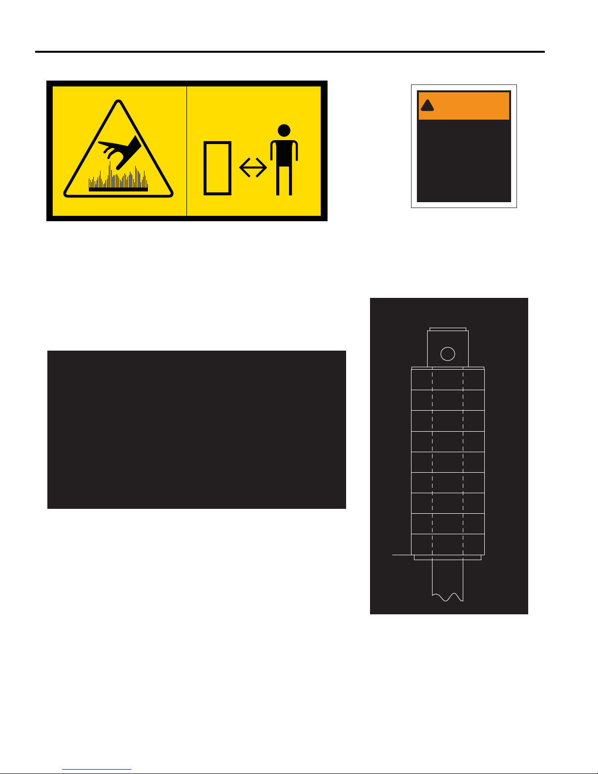
CUT
HEIGHT
W/ 1/2
SPACERS
5-1/4
4-3/4
4-1/4
3-3/4
3-1/4
2-3/4
2-1/4
1-3/4
1-1/4
3/4
CUT
HEIGHT
W/ 1/4
SPACER
5
4-1/2
4
3-1/2
3
2-1/2
2
1-1/2
1
16
4133609
Page 17
Familiarize yourself with the following decals. They are critical to the safe operation of the machine. REPLACE
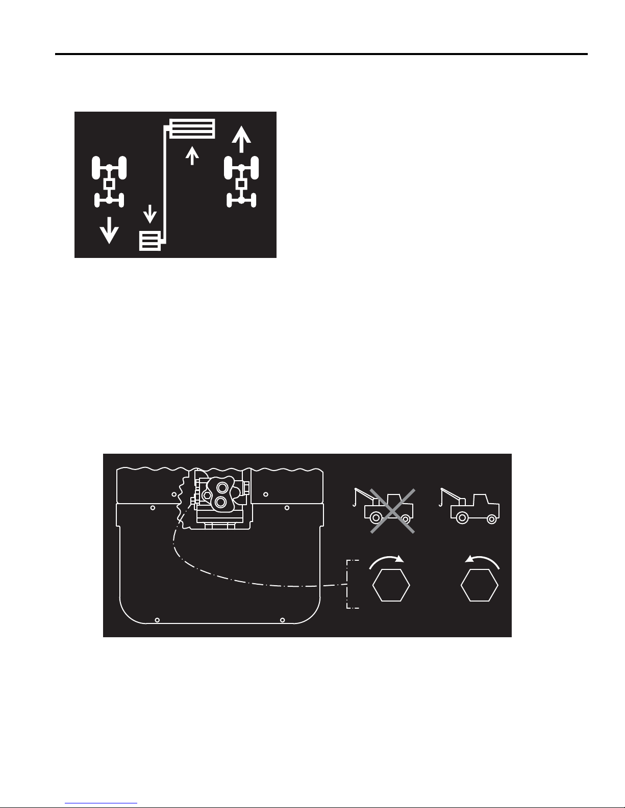
Tow Valve
Vehicle canNormal
Operation be towed
(Closed) (Open)
Traction Pedal
ReverseForward
DAMAGED DECALS IMMEDIATELY.
DECALS 3
3008521
3008682
17
Page 18
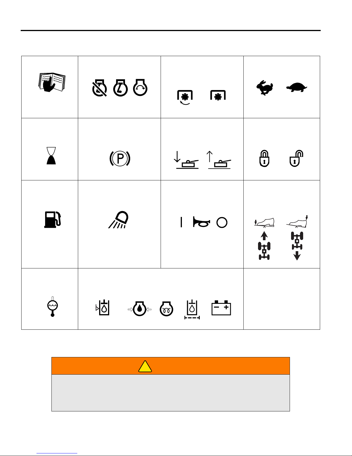
4 CONTROLS
Read Manual
High Low
Engine Throttle
PTO
Lock Unlock
Forward Reverse
Travel
Cruise Control
Off Run
Engine
Start
Parking Brake
ON
OFF
Coolant
Temperature
Fuel
Mowers
Lower Raise
Work Lights
Hour Meter
Oil Level Switch
On Off/Test
Engine Oil
Pressure
Glow
Plug
Hydraulic
Oil Filter
Battery
Charge
Warning Lights
Hydraulic
Oil Level
D
!
4 CONTROLS
4.1 ICONS___________________________________________________________________
Never attempt to drive the mower unless you have read the Safety, Operation, &
Maintenance Manual and know how to operate all controls correctly.
Familiarize yourself with the icons shown above and what they represent. Learn the
location and purpose of all the controls and gauges before operating this mower.
18
WARNING
Page 19
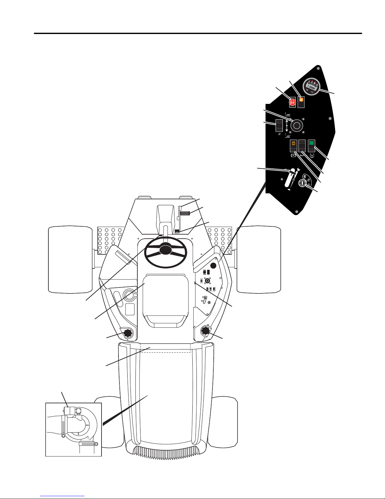
CONTROLS 4
A
E
M
U
F
J
S
V
C
B
G
K
L
R
D
H
P
N
T
W
P
E
F
A Tilt Steering Lever
B Mow Speed Stop
C Traction Pedal - Forward
D Traction Pedal - Reverse
E
Seat Adjustment
F Hydraulic Oil Cap/Dipstick
G Air Cleaner Indicator
H Fuel Cap
J Alarm
K Controller / Fuses
L Horn Switch
M Glow Plug Light
N Mower Lift Lever
P PTO Switch
R Light Switch
S Traction Control Switch
T Engine Throttle
U Ignition Switch
V Combination Gauge
W Brake Switch
4.2 CONTROLS_______________________________________________________________
19
Page 20
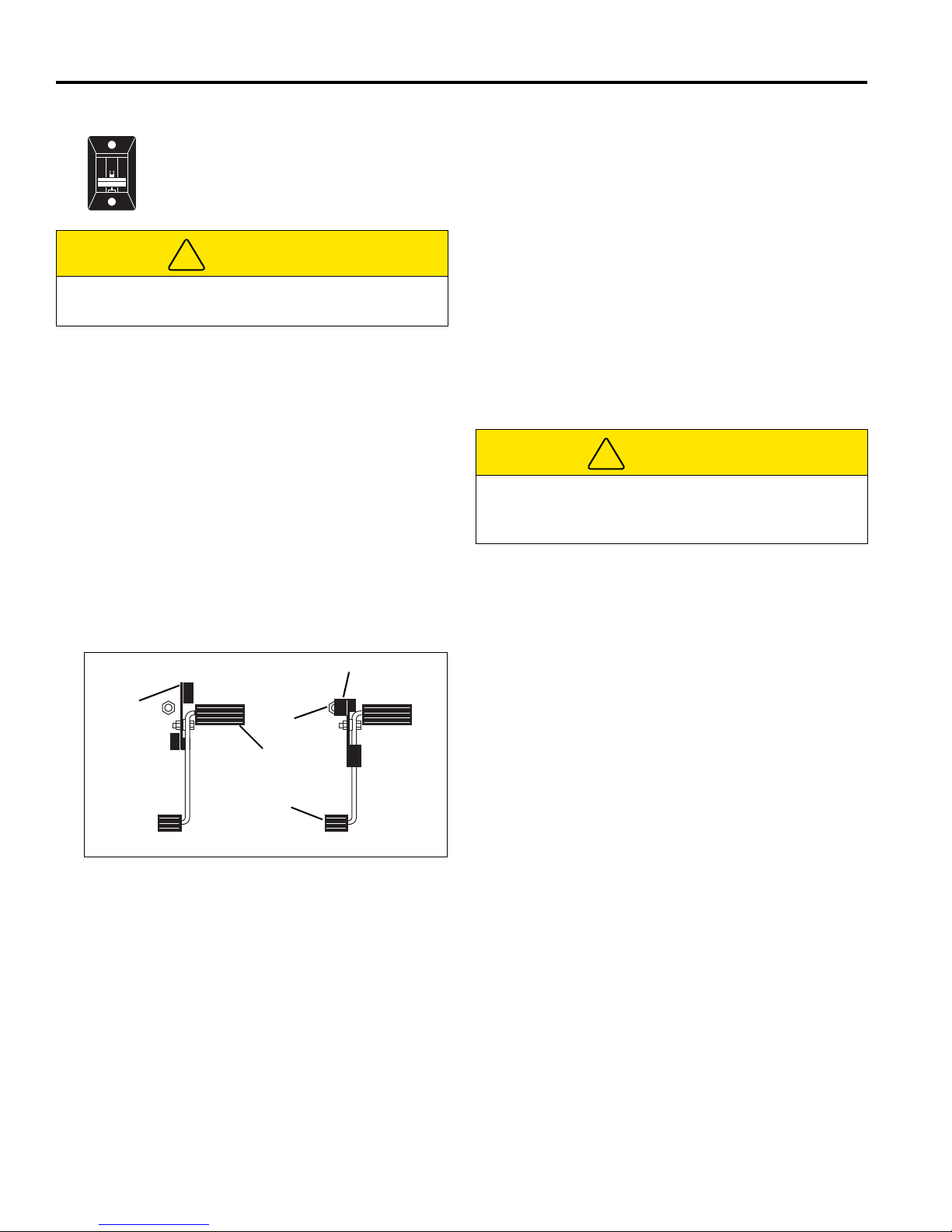
4 CONTROLS
!
B
3
Transport Speed
Mow Speed
B
1
B
2
C
D
!
A. Tilt Steering Lever
Pull lever up to release steering column. Tilt
column up or down to position desired.
Release lever to lock steering column in
place.
CAUTION
Never adjust steering while mower is moving. Stop
unit and set parking brake before adjusting.
B. Mow Speed Stop
Limits forward speed while mowing. To operate at
lower travel speed while mowing, rotate lever so it
contacts stop screw (B
travel pedal is pressed. To travel at full speed, set
lever in position shown (B
adjusted to set specific mow speeds. See Section
8.2.
C. Traction Pedal - Forward
Press front of pedal down for forward travel. Release
pedal to slow mower and stop.
) on floor board when forward
1
). Stop screw (B2) can be
3
H. Fuel Cap
Fill fuel tank with No. 2 diesel fuel, minimum Cetane
Rating of 45. See Section 5.11.
J. Alarm
The alarm, along with the warning lights on the
combination gauge (V), sounds to alert the operator
to conditions requiring immediate attention. See
Section 4.4.
K. Controller / Fuses
The controller is located under the rear hood directly
behind the operator’s seat. It is equipped with lights
to aid in monitoring and problem solving the electrical
system of the mower.
Two spade type fuses are located on the controller.
To replace fuses remove the access panel.
CAUTION
Service to the electrical system must be performed by
a trained technician. Before replacing fuses turn
mower off and remove key from ignition.
D. Traction Pedal - Reverse
Press rear of pedal down for reverse travel. Release
pedal to slow mower and stop. Allow mower to come
to a complete stop before reversing directions.
E. Seat Adjustment
Pull left side lever out to adjust seat forward or
backward. To adjust spring tension under seat turn
adjusting knob on front of seat.
F. Hydraulic Oil Cap / Dipstick
Fill to mark on dipstick using clean hydraulic fluid
while machine is cool. Do not overfill.
G. Air Cleaner Indicator
Indicates condition of air cleaner on engine. Clean or
replace air filter when red band appears in clear
window of indicator. See Section 7.4.
Figure 4A
20
Page 21
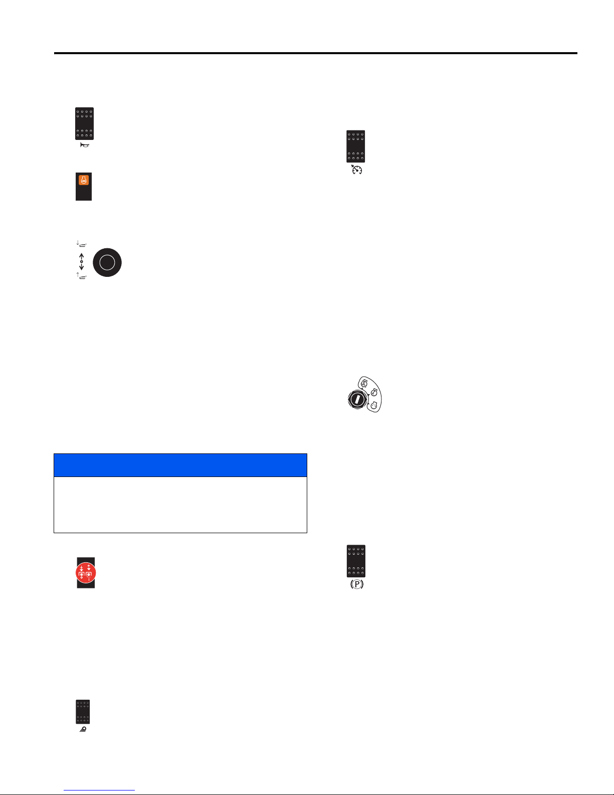
CONTROLS 4
4.3 CONTROL PANEL _________________________________________________________
L. Horn Switch
This switch is used sound the horn.
M. Warning Lights
When ignition switch (U) is turned to RUN
position, glow plug light indicates that the glow
plugs are energized. Wait until light goes out
to start the engine.
S. Traction Control
Press and release switch to enable controller
traction control system. This system reduces
down pressure on decks by pulsing the lift
circuit, transferring weight to mower.
Reducing down pressure improves traction,
but may cause decks to float up creating an
uneven cut. Light on switch will be on wh en system is
active.
N. Mower Lift lever
The mower lift lever raises and lowers
the mowers and operates in either
automatic or manual mode. Push lever
forward to lower mowers, pull back to
raise mowers.
Manual Mode - Set mow switch (Q) in its OFF
(down) position. In this position all mowers will raise
or lower while pressure is applied to the lift lever.
Automatic Mode - Set mow switch (Q) in its ON (up)
position. In automatic mode the mowers will lower
and start automatically with a momentary forward
movement of the lift lever. In this mode mowers will
only raise to a “crosscut” position with a momentary
backward movement of the lift lever.
To raise mowers to their transport position, hold lever
until mowers are fully raised.
NOTICE
While in an Automatic Mode lift or lower cycle, which
lasts approximately 3 seconds, moving the lift lever in
the opposite direction will turn all mowers off, and
manual mode will start for the position selected.
P. PTO Switch
The PTO switch is a 2-position knob type
switch used to engage and disengage the
mowers. It also sets the mower lift lever (P) in
manual or automatic mode. Set PTO switch
in its disengaged (down) position when
starting the mower.
When the PTO switch is in the engaged (UP)
position, the traction control system is automatically
enabled, and the lift lever is placed in Automatic
Mode.
Press and release switch again to deactivate traction
control. This will reduce traction, but improves deck
contact with ground.
The traction control system is automatically enabled
when the PTO switch is placed in the engaged (UP)
position. Press and release traction control switch to
cancel traction control.
T. Engine Throttle
Controls engine speed. Run machine at full throttle
during normal machine operation.
U. Ignition Switch
The ignition switch has three positions.
OFF- RUN (ON) - START. In the RUN
position the controller program is running
and input and output circuits are being
monitored. See Section 5.4 and Section
9.2.
V. Combination Gauge
Used to display fuel level, operating hours, and
indicate mower alerts. See Section 4.4.
W. Parking Brake Switch
To engage parking brake, slide lock forward
and depress top of switch. Parking brake light
on combination gauge (V) will turn on. Normal
reel operation is disabled wit h parking brake
engaged.
To disengage parking brake, depress rear of switch.
Parking brake light on combination gauge will turn
off.
NOTE:
in the Disengaged position.
Mower will not start with parking brake switch
R. Light Switch
Controls operation of work lights. Press front of
switch to turn lights on. Press rear portion of
switch to turn lights off.
21
Page 22
4 CONTROLS
P
EF
!
!
P
4.4 OPERATOR ALERTS_______________________________________________________
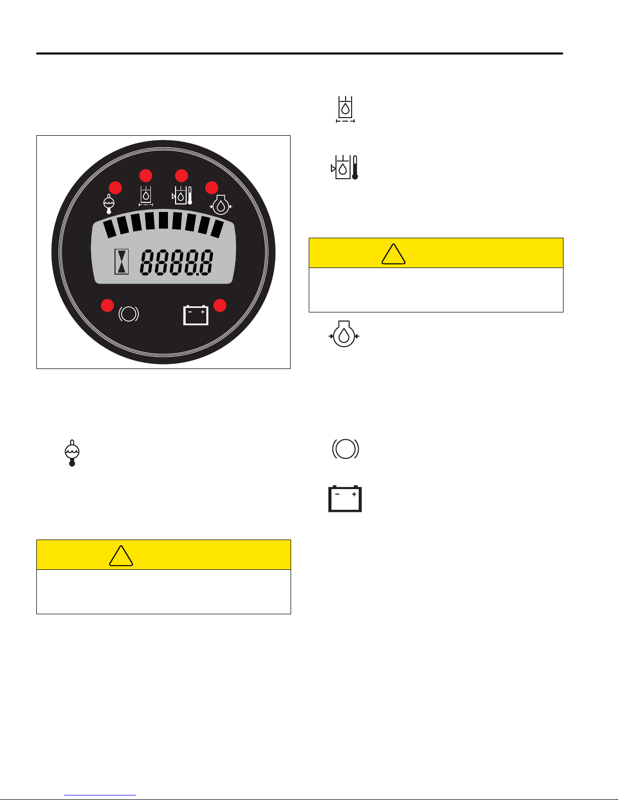
The Combination gauge displays operating hours, fuel
level, and has lights to alert operator to mower
conditions.
Figure 4B
4.4.1 Indicator Lights ___________________
The combination gauge has six indicator lights to indicate
system functions.
Coolant Temperature Light: Red coolant
temperature light indicates that coolant
temperature is above 230° F (110° C). Shut
down unit immediately. Remove debris
such as leaves and grass clippings that
may be restricting air flow through rear
screen and radiator. If engine continues to
run hot, return mower to a service area.
Hydraulic Oil Filter Light: Red oil filter
light indicates the hydraulic filter needs to
be replaced. Return mower to service area
as soon as possible and replace filters.
Hydraulic Oil Level Light: Red hydraulic
oil level light indicates a low fluid level in the
hydraulic tank. Shut mower down
immediately. Visually inspect mower for
obvious signs of leaks around connections,
hoses, and hydraulic components. Return
mower to service area for maintenance.
CAUTION
Hydraulic fluid is under pressure. Shut mower down
and allow fluid to cool before checking fluid level, or
adding oil to hydraulic tank.
Engine Oil Pressure Light: Red engine oil
pressure light indicates low engine oil
pressure. Shut down unit immediately.
Inspect oil level in engine. If oil light
remains on with oil at proper level, shut off
engine and tow or trailer mower back to a
service area. NEVER operate engine with
oil light on, severe damage to the engine
can occur.
Parking Brake Light: Red parking brake
light indicates the parking brake switch is
engaged. Do not depress traction pedal
with parking brake engaged.
Battery Light: Red battery light indicates
battery voltage has dropped below 11.5
volts for one minute. Return mower to
service area and inspect battery and
battery charging systems.
CAUTION
Diesel engine coolant is under pressure. Turn engine
off and allow fluid to cool before checking fluid level or
adding coolant to radiator.
22
Page 23

OPERATION 5
!
!
5 OPERATION
5.1 DAILY INSPECTION ________________________________________________________
2. Check the fuel supply, radiator coolant level,
CAUTION
The daily inspection should be performed only when
the engine is OFF and all fluids are cold. Lower
mowers to the ground, engage the p arking bra ke, stop
engine, and remove ignition key.
1. Perform a visual inspection of the entire unit, look for
signs of wear, loose hardware, and missing or
damaged components. Check for fuel or oil leaks to
ensure connections are tight and hoses and tubes
are in good condition.
5.2 INTERLOCK SYSTEM ______________________________________________________
crankcase oil and air cleaner indicator. All fluids
must be at the full level mark with engine cold.
3. Make sure all mowers are adjusted to the same
cutting height.
4. Visually check tires for proper inflation.
5. Test the interlock system.
Note: For more detailed maintenance information,
adjustments and maintenance/lube charts, see the
Sections 6, 7, and 8.
1. The interlock system prevents the engine from
starting unless the parking brake switch is ON, the
traction pedal is in neutral and the PTO switch is
OFF. The system also stops the engine if the
operator leaves the seat with the PTO switch ON,
traction pedal out of NEUTRAL, or parking brake
switch OFF.
WARNING
Never operate equipment with the Interlock
System disconnected or malfunctioning. Do not
disconnect or bypass any switch.
2. Perform each of the following tests to insure the
interlock system is functioning properly. Stop the
test and have the system inspected and repaired if
any of the tests fail as listed below:
l the engine does not start in test 1;
l the engine does start during tests 2,3 or 4;
l the engine continues to run during tests 5 or 6.
Interlock System Check
3. Refer to the chart below for each test and follow the
check (4) marks across the chart. Shut engine off
between each test.
Test 1: Represents normal starting procedure. The
operator is seated, parking brake switch is ON, the
operator’s feet are off the pedals, and the PTO switch
is OFF. The engine should start.
Test 2: The engine must not start if the PTO switch is
ON.
Test 3: The engine must not st art if th e p ark ing brake
switch is OFF.
Test 4: The en gine mu st not start if the traction pedal
is pressed.
Test 5: Start the engine in the normal manner then
turn PTO switch ON and lift your weight off the seat.
H
Test 6: Start the engine in the normal manner then
turn parking brake switch OFF and lift your weight off
the seat. H
Test
1 444 44
2 4444 4
3 44444
4 44 444
5 4
6 4
Operator
Seated
Yes No On Off Yes No On Off Yes No
H
H
H Lift your weight off seat. The cutting units must stop rotating within seven (7) seconds.
Parking
Brake Switch
444
44 4
Traction Pedal
in Neutral
PTO
Switch
Engine
Starts
H
H
23
Page 24
5 OPERATION
!
!
!
!
5.3 OPERATING PROCEDURES_________________________________________________
WARNING
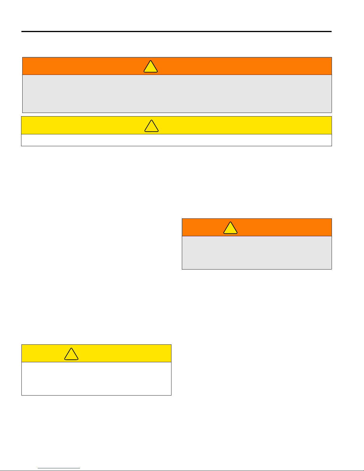
A Roll Over Protection Structure (ROPS) is included with this mower. Seat belts must be worn wh enever opera ting
a mower with a ROPS. Always keep seat belt snugly adjusted. DO NOT use seat belts on a mower without a
ROPS.
If the mower is overturning, hold onto the stee rin g wheel. Do no t attempt to jump out or leave the seat.
CAUTION
To prevent injury, always wear safety glasses, leather work shoes or boots, a hard hat, and ear protection.
1. Under no circumstances should the engine be
started without the operator seated on the mower.
Never start the engine with operator or bystanders
standing behind a discharge chute.
2. Never run the engine in an enclosed area.
3. Keep hands and feet away from moving parts and
cutting units. If possible, do not make adjustments
with the engine running.
4. Do not operate mower or attachments with loose,
damaged or missing components. Whenever
possible mow when grass is dry.
5. First mow in a test area to become thoroughly
familiar with the operation of the mower and control
levers.
6. Study the area to determine the best and safest
operating procedure. Consider the height of the
grass, type of terrain, and condition of the surface.
Each condition will require certain adjustments or
precautions.
7. Be aware of mower discharge direction and never
direct discharge of material toward bystanders.
Never allow anyone near the machine while in
operation. The owner/operator is responsible for
injuries inflicted to bystanders and/or damage to
their property.
CAUTION
9. Always turn PTO switch OFF to stop blades when
not mowing.
10. Disengage the drive motors, raise the mowers and
slow down when crossing paths or roadways. Look
out for traffic.
11. Stop and inspect the equipment for damage
immediately after striking an obstruction, or if the
machine begins to vibrate abnormally. Have the
equipment repaired before resuming operation.
WARNING
Before you clean, adjust, or repair this equipment,
always disengage all drives, lower implements to the
ground, engage parking brake, stop engine, and
remove key from ignition switch to prevent injuries.
12. Slow down and use extra care on hillsides. Read
Section 5.9. Use caution when operating near drop
offs.
13. Look behind and down before backing up to be sure
the path is clear. Use care when approaching blind
corners, shrubs, trees or other objects that may
obscure vision.
14. Never use your hands to clean cutting units. Use a
brush to remove grass clippings from blades.
Blades are extremely sharp and can cause serious
injuries.
Before mowing, pick up all debris such as rocks, toys,
and wire which can be thrown by the machine. Enter a
new area cautiously. Always operate at speeds that
allow you to have complete control of the mower.
8. Use discretion when mowing near gravel areas
(roadway, parking areas, cart paths, etc.). Stones
discharged from the implement may cause serious
injuries to bystanders and/or damage the
equipment.
24
Page 25
OPERATION 5
!
5.4 STARTING________________________________________________________________
Wait until glow plug light (M) goes out, then
NOTICE
IMPORTANT: Do not use starting assist fluids. Use
of such fluids in the air intake system may be
potentially explosive or cause a “Runaway” engine
condition and could result in serious engine damage.
immediately turn ignition key (U) to “START” ( )
position. Release as soon as engine starts. Allow 30
seconds between start-up attempts to allow time for
engine starter motor to cool.
All warning lights should go off after engine starts.
Allow engine to gradually become warm before
operating at high RPM.
WARNING
To prevent injuries, sit in the seat, engage parking
brake, place traction pedal in Neutral, and PTO switch
in OFF position before attempting to start the engine.
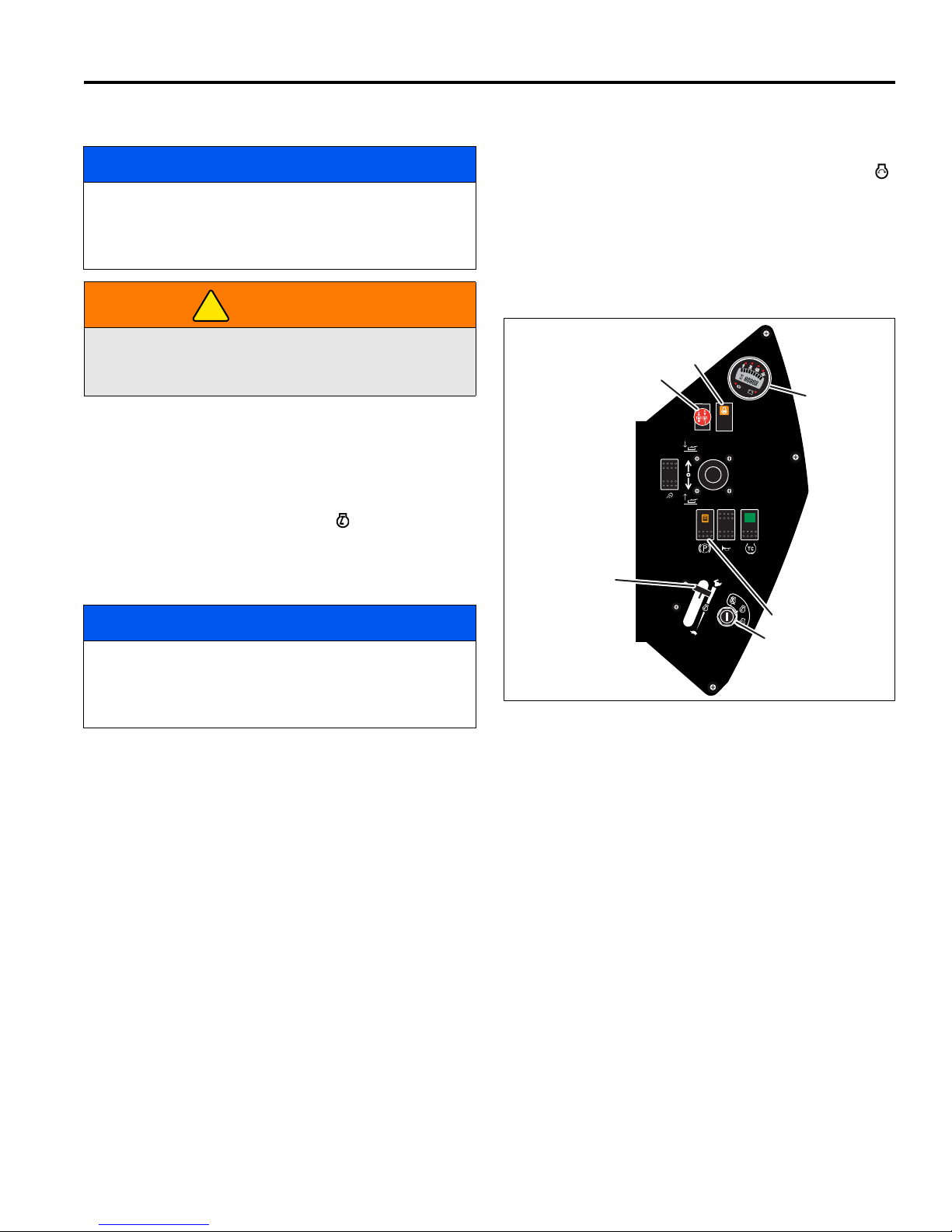
1. Sit in operator’s seat, make sure the PTO switch (P)
is OFF (down) and the parking brake switch (W) is
ON. Remove feet from pedals. Always use the seat
belt when operating mowers equipped with a ROPS.
2. Set throttle lever (T) to half throttle.
3. Turn ignition switch (U) to RUN ( ) position.
Note: At this time the warning lights on the
combination gauge (V) and glow plug light (M) will
come on. Check that lights are operating.
NOTICE
Do not hold key in “START” position for more than 10
seconds at a time. After 10 seconds the starting circuit
will shut down and must be reset by returning the key
to the OFF position.
T
M
P
E
F
P
V
W
U
Figure 5A
5.5 STOPPING / PARKING______________________________________________________
To stop:
Remove your foot from traction pedal. The mower will
automatically brake when the traction pedal returns to
Neutral. Always engage parking brake, shut off engine,
and remove key before leaving operator seat for any
reason.
To park the mower under normal conditions:
1. Disengage the PTO switch (Q) then raise the
implements in the transport position and move away
from the area of operation.
2. Select a flat and level area to park.
a. Release traction pedal to bring the mower to a
complete stop.
b. Disengage all drives, lower implements to the
ground, engage parking brake, reduce throttle to
idle.
3. Engage parking brake, stop the engine, and always
remove the ignition key.
If an emergency arises and the mower must be parked in
the area of operation, follow the guidelines outlined by
the grounds superintendent. If the mower is parked on an
incline, chock or block the wheels.
25
Page 26

5 OPERATION
!
5.6 TO DRIVE / TRANSPORT____________________________________________________
Read and follow all safety notes contained in this manual
when driving or transporting mower. When operating in
reverse look behind you to ensure you have a clear path.
Important: If this mower is driven on pu blic roads, it must
comply with federal, state and local ordinances. Con tact
local authorities for regulations and equipment
requirements.
To raise mowers to their transport position:
Set PTO switch to OFF. Pull mower lever back. Hold
lever until mowers are up and lift arms are in their fully
raised (transport) position.
Important: The mow switch should be OFF while
transporting mower.
5.7 MOWING_________________________________________________________________
3. To lift mowers, pull mower lever back and release.
WARNING
To prevent serious injuries, keep hands, feet, and
clothing away from cutting unit when the blades are
moving.
NEVER use your hands to clean cutting units. Use a
brush to remove grass clippings from blades. Blades
can be sharp and could cause injuries.
DO NOT operate mowers without rear discharge
chutes or mulching plate installed.
To mow:
1. Set PTO switch to its ON (Up) position. This also sets
the mower lever to automatic mode and
automatically enables the Traction Control System.
[See 4.3].
2. Press mower lever forward momentarily to lower
mowers. Mowers will begin turning automatically
when cutting units have lowered.
Mowers will stop turning and raise to their crosscut
position. To lift mowers to their transport position
continue to hold lever until mowers are completely
raised.
4. To cancel traction control, press and release traction
control switch (S). [See 4.3].
Always mow with the engine at full throttle.
To install mulching plate:
An optional mulching plate can be used instead of the
rear discharge chute. Do not operate mower without rear
discharge chute or mulching plate installed.
1. Place PTO switch in OFF (down) position, lower
mowers to the ground, engage parking brake and
stop engine.
2. Remove three nuts securing discharge chute to
mower housing.
3. Remove discharge chute and assemble mulching
plate. Secure with three nuts removed previously.
Store the discharge chute in a safe location for
future use.
5.8 MOWING SPEED __________________________________________________________
Cutting quality is better at speeds well below the
transport speed of the mower. An initial mow speed of 6
to 7 MPH (10 to 11 kph) is set at the factory and should
be satisfactory for most cutting conditions. Local turf
conditions, however, may respond better to a different
speed. If an adjustment is needed, refer to Section 8.2.
26
Page 27
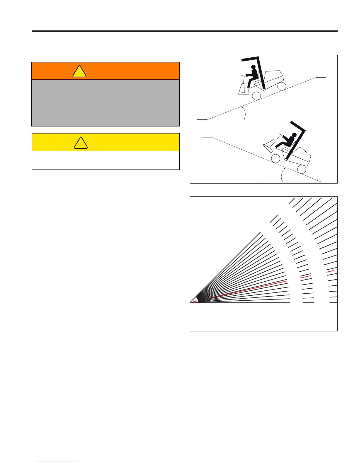
5.9 HILLSIDE OPERATION _____________________________________________________
!
!
0°
Degrees are shown to nearest 1/4°
General Slope of Roadway Embankment - 45°
Steepest Grass Area - 31°
Slope of Average Roof - 19-1/4°
2nd Class Highway Maximum Grade - 4-1/2°
Toll Road or Freeway - 1-3/4°
0%
2-3/4°
5%
5-3/4°
1
0%
8-
1
/2°
15%
11-1/4°
20%
1
4°
25%
16-3/4°
30%
19-1/4°
35%
2
1-3/
4°
40%
24-1/4°
45%
26-1/2°
50%
28-3/4°
55%
31°
60%
33°
65%
35°
70%
36-3/4°
75%
38-3/4°
80%
40-1/4°
85%
42°
90%
43-1/2°
95%
45°
100%
Degrees
Grade
WARNING
To minimize the possibility of overturning, the safest
method for operating on hills and terraces is to travel
up and down the face of the slope (vertically), not
across the face (horizontally). Avoid unnecessary
turns, travel at reduced speeds, and stay alert for
hidden hazards.
CAUTION
Do not operate this mower on slopes greater than
15.7° or a 28% grade.
The mower has been designed for good traction and
stability under normal mowing conditions. Use caution
when operating on slopes, especially when the grass is
wet. Wet grass reduces traction and steering control.
1. Always mow with the engine at full throttle, but
reduce forward speed to maintain the proper cutting
frequency.
2. Activate traction control (S) as required to improve
weight distribution between decks and mower. [See
4.3].
3. If the mower tends to slide or the tires begin to mark
the turf, angle mower into a less steep grade until
traction is regained or tire marking stops.
4. If mower continues to slide or mark the turf, the
grade is too steep for safe operation. Do not make
another attempt to climb, and back down slowly.
5. When descending a steep slope, always lower
implements to the ground to reduce the risk of
mower overturning.
Correct tire pressure is essential for maximum traction.
Front..........................16 psi (1.10 BAR)
Rear..........................12 psi (0.86 BAR)
OPERATION 5
15.7°
Maximum
28%
15.7°
Maximum
28%
Figure 5B
Figure 5C
27
Page 28
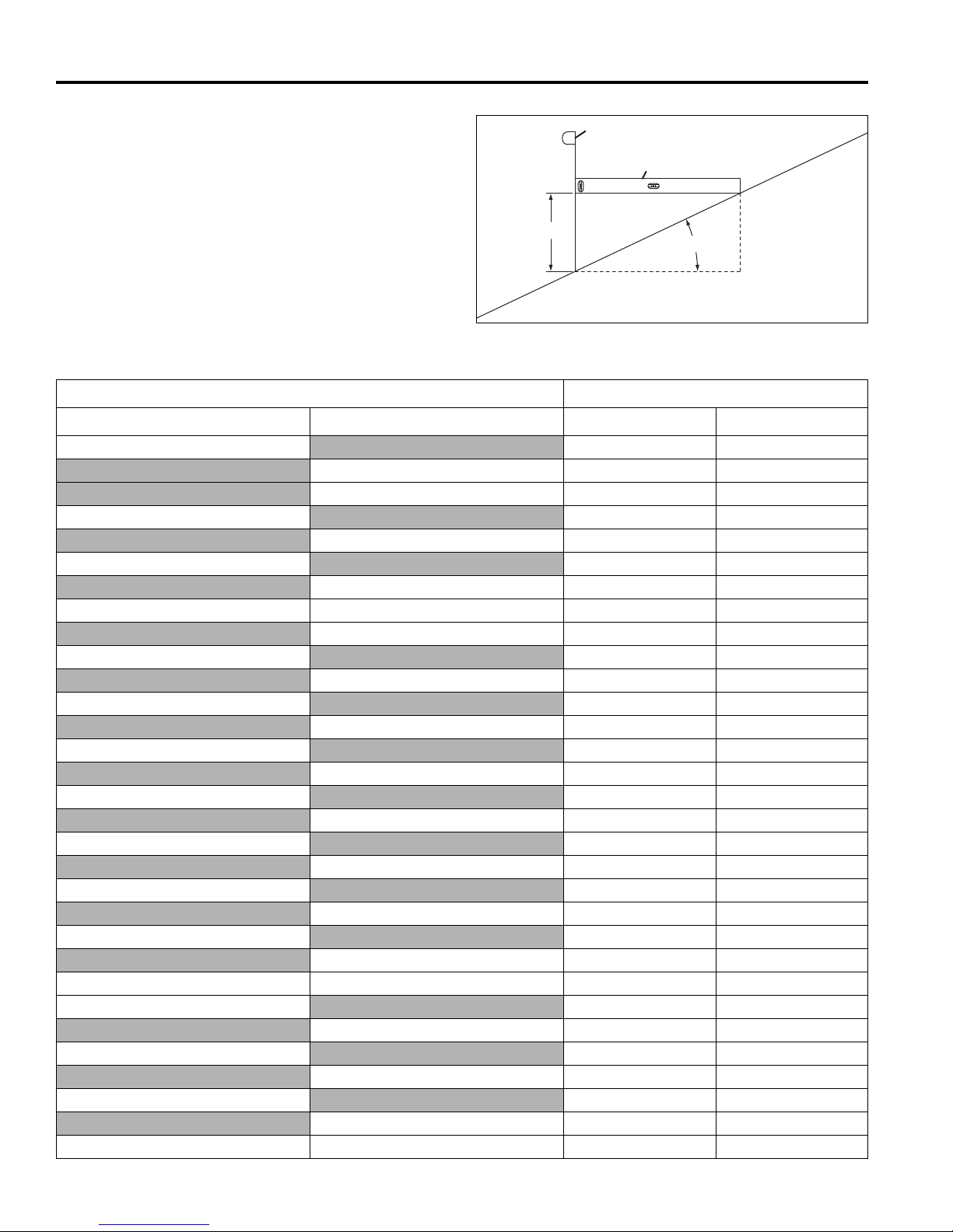
5 OPERATION
C
A
B
D
How to calculate a slope:
Tools Required:
Level (A), either 1 yard, or 1 meter long.
Tape measure (B).
With the level (A) positioned horizontally, measure the
distance (C) with tape measure (B). Use the chart to
calculate either the slope angle or the % grade of the
slope (D).
Height (C) Result (D)
Inches with 1 Yard Level (A) Millimeters with 1 Meter Level (A) Slope in Degrees Slope Grade %
Figure 5D
28
3
100 5.7 10.0
150 8.5 15
6
200 11.3 20.0
7.5
225 12.7 22.5
9 250 14 25.0
275 15.4 27.5
10
300 16.7 30.0
11
325 18.0 32.5
12
350 19.3 35.0
13
375 20.6 37.5
14
400 21.8 40.0
15
425 23.0 42.5
16
475 25.4 47.5
18 500 26.6 50.0
20
25
30
36 1000 45.0 100
600 31.0 60.0
800 38.7 80.0
900 42.0 90
4.8 8.3
9.5 16.7
11.8 20.8
15.5 27.8
17.0 30.6
18.4 33.3
19.9 36.1
21.3 38.9
22.6 41.7
24 44.4
29.1 55.6
34.8 69.4
39.8 83.3
Page 29
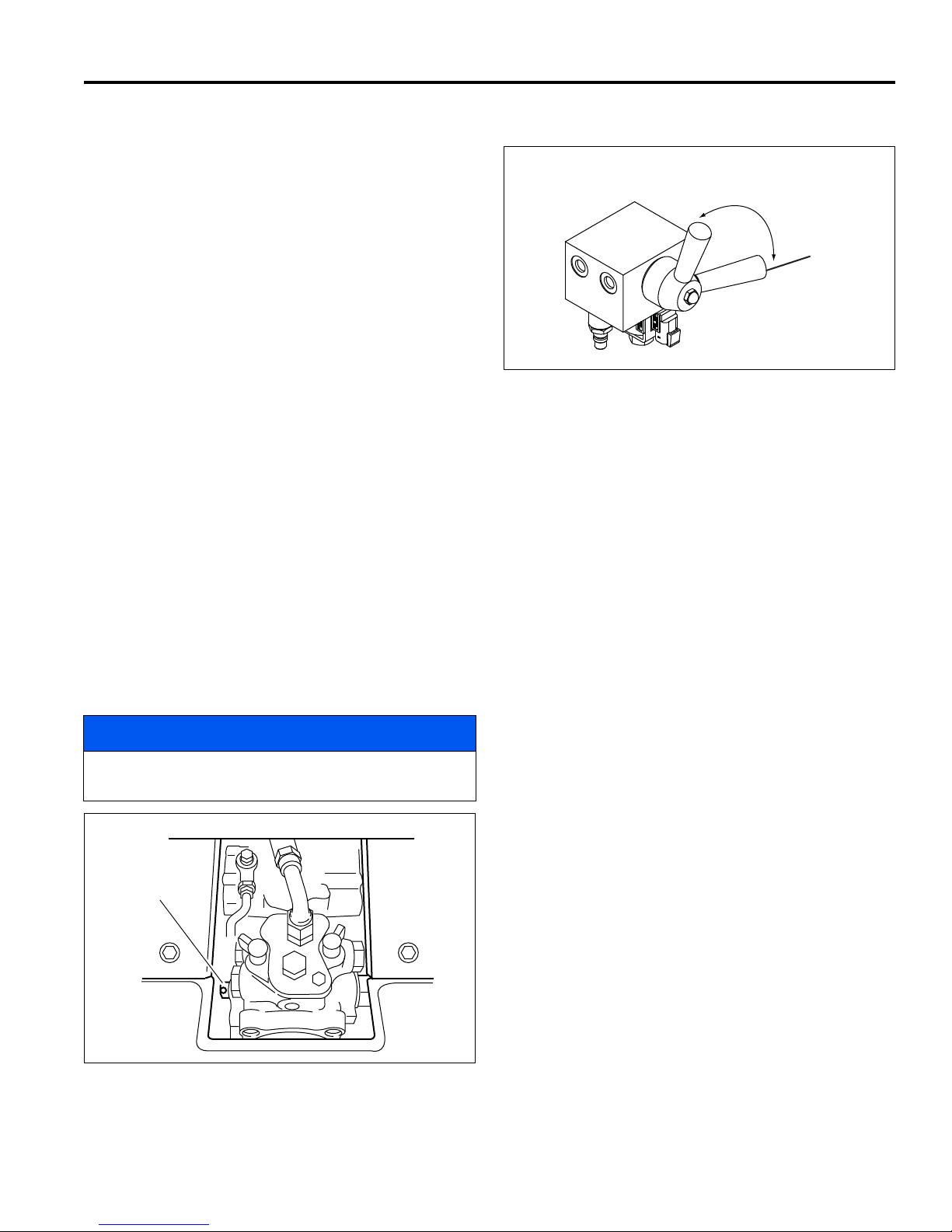
OPERATION 5
A
LF006
Brake released
for towing.
Brake engaged
(Normal operation)
B
5.10 TOWING / TRAILERING _____________________________________________________
If the mower experiences problems and must be shut
down and removed from the area, it should be loaded
onto a trailer for transport. If a trailer is not available, the
unit can be towed slowly for short distances.
Use care when loading and unloading mower. Fasten
mower to trailer to prevent mower from rolling or shifting
during transport.
Long Distance Trailering / Transport. If the mower is to
be trailered on the highway, before strapping to trailer,
close fuel shut off valve and inflate tires to maximum
pressure listed on side of tire. Reduce tire pressure to
normal after removing from trailer. [See 5.9].
Before towing, open tow valve. The tow valve permits
moving the mower without starting the engine and
prevents possible damage to hydraulic components.
The tow valve (A) is located on the hydraulic drive pump
beneath the operators seat. Remove cover from floor in
front of operator’s seat. To open valve, use a wrench or
insert a pin or small screw driver into the small hole in the
valve stem. Turn the valve counterclockwise 90°.
Rotate brake release lever (B) counter clockwise. Brake
release lever is located under floor panel, near right front
axle mount. T o release the brakes, turn steering wheel for
right hand turn (clockwise) until resistance is felt.
Before towing make sure cutting units are raised. If they
cannot be raised, remove them from the mower.
Close tow valve (A) completely, rotate brake release
lever (B) clockwise, and replace floor panel after towing.
Figure 5F
NOTICE
Do not exceed 2 MPH (3.2 KPH) while towing. Long
distance towing is not recommended.
Figure 5E
29
Page 30

5 OPERATION
!
!
!
5.11 DAILY MAINTENANCE _____________________________________________________
Important: For more detailed maintenance information,
adjustments and maintenance/lubrication charts, see
Sections 6, 7, and 8.
1. Park the mower on a flat, level surface. Fully lower
the implements to the ground, engage parking brake,
stop the engine and remove key from ignition switch.
2. Grease and lubricate all points if required. To
prevent fires, wash the cutting units and mower after
each use.
a. Use only fresh water for cleaning your equip-
ment.
b. Do not use high pressure spra y.
c. Do not spray water directly at the instrument
panel, or any electrical components.
d. Do not spray water into the cooling air intake or
the engine air intake.
NOTICE
Do not wash a hot or running engine. Use
compressed air to clean the mower, engine and
radiator fins to reduce the potential for corrosion and
moisture contamination.
3. Fill mower’s fuel tank at the end of each operating
day to full mark on fuel gauge.
Always use clean, fresh #2 diesel fuel. Minimum
Cetane Rating 45.
4. Handle fuel with care - it is highly flammable.
Use an approved container; the spout must fit inside
the fuel filler neck. Avoid using cans and funnels to
transfer fuel.
WARNING
Never remove the fuel cap from the fuel tank, or add
fuel, when the engine is running or while the engine is
hot.
Do not smoke when handling fuel. Never fill or drain
the fuel tank indoors.
Do not spill fuel. Clean spilled fuel immediately.
6. Never overfill or allow the tank to become empty.
7. Inspect hydraulic hoses and tubes daily. Look for
wet hoses or oil spots and replace worn or
damaged hoses and tubes before operating the
machine.
WARNING
To prevent serious injury from hot, high pressure oil,
never use your hands to check for oil leaks; use p a per
or cardboard.
Hydraulic fluid escaping under pressure can have
sufficient force to penetrate skin. If fluid is injected into
the skin, it must be surgically removed within a few
hours by a doctor familiar with this form of injury or
gangrene may result.
8. Check the engine oil and hydraulic oil at the start of
each day, before starting the engine. If the oil level
is low, remove the oil filler cap and add oil as
required. Do not overfill.
WARNING
To prevent serious bodily injury from hot coolant or
steam blow-out, never attem pt to remove the ra diator
cap while the engine is running. Stop the engine and
wait until it is cool. Even then, use extreme care when
removing the cap.
Do not pour cold water into a hot radiator. Do not
operate engine without a proper coolant mixture.
Install cap and tighten securely.
9. After engine has cooled, check coolant level.
Radiator should be full and recovery bottle should
be up to the cold mark.
10. Park machine in designated area. Engage parking
brake and remove key. Place key in a secure
location to prevent unauthorize d us e of equ i pm e nt .
11. Check the engine oil and hydraulic oil at the start
and end of each day. If the oil level is low, remove
the oil filler cap and add oil as required. Do not
overfill.
Never handle or store fuel containers near an open
flame or any device that may create sparks and ignite
the fuel or fuel vapors.
Be sure to reinstall and tighten fuel cap securely.
5. Store fuel according to local, state or federal
ordinances and recommendations from your fuel
supplier.
30
Page 31

MAINTENANCE & LUBRICATION CHARTS 6
!
6 MAINTENANCE & LUBRICATION CHARTS
6.1 GENERAL ________________________________________________________________
2. Lubricate with grease that meets or exceeds NLGI
WARNING
Before you clean, adjust, or repair this equipment,
disengage all drives, lower implements to the ground,
engage parking brake, stop engine and remove key
from ignition switch to prevent injuries.
1. Always clean grease fittings before and after
lubrication.
6.2 MAINTENANCE CHART_____________________________________________________
Recommended Service and Lubrication Intervals
Grade 2 LB specifications. Apply grease with a
manual grease gun and fill slowly until grease
begins to seep out. Do not use compressed air.
3. For smooth operation of pivot points and other
friction points, apply several drops of SAE 30 oil
every 50 hours or as required.
4. Remove wheels and repack bearings once a year.
Air Cleaner
Battery Charge
Belt
Cooling System
Engine Oil
Engine Oil Filter
Fuel Lines and Clamps
Fuel Filter
Grease Fittings - F1
Grease Fittings - F2
Hydraulic Hoses and
Tubes
Hydraulic Oil
Hydraulic Oil FIlters
Muffler and Exhaust
Radiator Screens
Tires
Steering System
Wheel Bearings
Wiring
Every
8-10
Hours
I-A* I-A R 8.3
I-C-A R 7.15
I R* R***** 7.2 III
I*** I 7.11
I-C/AR 7.15
Every
50
Hours
R* R***** 7.3
L6.3II
I-A R** 7.12 IV
R* R-AR 7.13
I-A 7.17
I* I-A
I* I 7.14
Every
100
Hours
AR R 7.4
I**** 7.9
I
Every
250
Hours
L6.3II
Every
400
Hours
R7.6
I7.10
Every
500
Hours
Every
1000
Hours
Yearly See
Section
L I
Lubricant
Type
A - Add or Adjust C - Clean I - Inspect L- Lubricate R - Replace AR - As Required
* Indicates initial service for new machines.
** Or yearly, whichever comes first.
*** Inspect visible hoses and tubes for leaks or oil marks.
**** Inspect electrolyte level. See 7.7
***** Engine oil and filter intervals must be shortened if
improper diesel fuel is used.
I Pack bearings with NLGI Grade 2 (Service Class GB)
II Manual grease gun with NLGI Grade 2 (Service Class
LB).
III Engine Oil - See Section 7.3
IV Jacobsen Hydraulic Oil - SAE 10W30 or Greens Care
68
31
Page 32
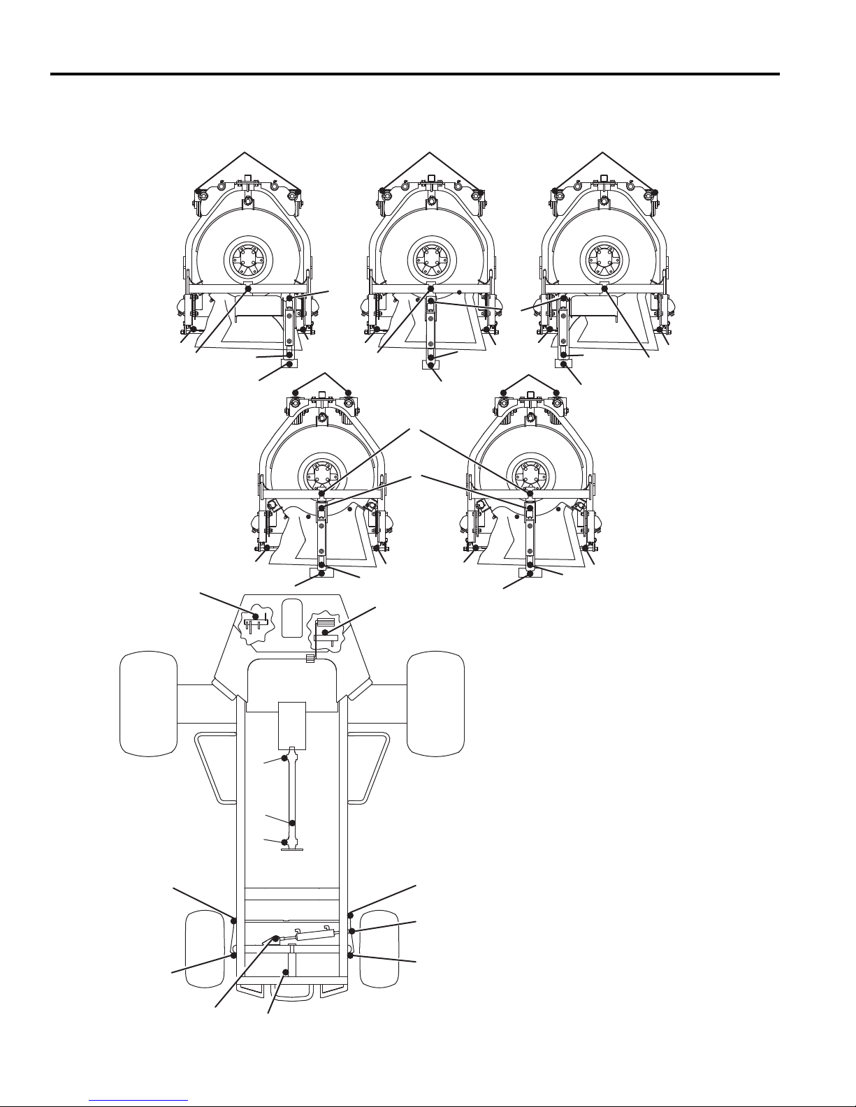
6 MAINTENANCE & LUBRICATION CHARTS
444
5
11
Grease Fittings
F1 - 50 Hours (Every Week)
1 Mower Pivot (5)
2 Lift Arm Pivot (5)
3 Lift Cylinders (10)
4 Caster Pivot and Caster Wheels (10)
5 Mower Rear Roller (10)
6 Axle Pivot
7 Traction Pedal Pivot
8 Ball Joint (2)
9 Steering Pivot (2)
10 Steering Cylinder (2)
F2 - 100 Hours
11 U-joint Driveshaft (3)
6.3 LUBRICATION CHART _____________________________________________________
3
3
5
11
6
8
3
2
12
12
12
5
2
555
4
1
3
3
7
8
10
3
2
555
2
4
3
2
5
3
1
9
10
32
9
Page 33

MAINTENANCE 7
!
7 MAINTENANCE
7.1 GENERAL ________________________________________________________________
b. Keep all moving parts properly adjusted and
WARNING
Before you clean, adjust, or repair this equipment,
disengage all drives, lower implements to the ground,
engage parking brake, stop engine, and remove key
from ignition switch to prevent injuries
Make sure the mower is parked on a solid and level
surface. Never work on a mower that is supported
only by the jack. Always use jack stands.
1. Adjustment and maintenance should always be
performed by a qualified technician. If proper
adjustments cannot be made, contact an Authorized
Jacobsen Dealer.
2. Inspect the equipment on a regular basis, establish
a maintenance schedule and keep detailed record s.
a. Keep the equipment clean.
3. Do not wear jewelry or loose fitting clothing when
4. Use the illustrations in the Parts Catalog as
5. Recycle or dispose of all hazardous materials
lubricated.
c. Replace worn or damaged part s before oper ating
the machine.
d. Keep all fluids at their proper levels.
e. Keep shields in place and all hardware securely
fastened.
f. Keep tires properly inflated.
making adjustments or repairs.
reference for the disassembly and reassembly of
components.
(batteries, fuel, lubricants, anti-freeze, etc.)
according to local, state, or federal regulations.
7.2 ENGINE _________________________________________________________________
IMPORTANT: A separate Engine Manual, prepared by
the engine manufacturer, is supplied with this
mower. Read the Engine Manual carefully until you
are familiar with the operation and maintenance of
the engine. Proper attention to the engine
manufacturer’s directions will assure maximum
service life of the engine. To order replacement
Engine manuals contact the engine manufacturer.
The proper break-in of a new engine can make a
considerable difference to the performance and life of th e
engine.
During the break-in period, Jacobsen recommends the
following:
1. During the first 50 hours of operation, a new engine
should be allowed to reach an operating temperature
of at least 140°F (60°C) prior to operation at full load.
2. Check the engine oil level twice daily during the first
50 hours of operation. Higher than normal oil
consumption is not uncommon during the initial
break-in period.
3. Change engine oil and oil filter element after first 50
hours of operation.
4. Check and adjust fan and alternator belts.
5. Refer to Section 6.2 and Engine Manual for specific
maintenance intervals.
If the injection pump, injectors or the fuel system require
service, contact an authorized Jacobsen Dealer.
NOTICE
The mower is designed to operate and cut most
efficiently at the preset governor setting. Do not
change the engine governor settings or overspeed the
engine.
7.3 ENGINE OIL ______________________________________________________________
Check the engine oil at the start of each day, before
starting the engine. If the oil level is low, remove oil filler
cap, and add oil as required.
Perform initial oil change after first 50 hours of operation
and every 400 hours thereafter. See Engine Manual.
Use only engine oils with API classification CJ-4.
Above 77°F (25°C) SAE 30W or SAE10W30/
10W40
32 to 77°F (0 to
25°C)
Below 32°F (0°C) SAE10W or SAE 10W30/
SAE 20W or SAE 10W30/
10W40
10W40
33
Page 34
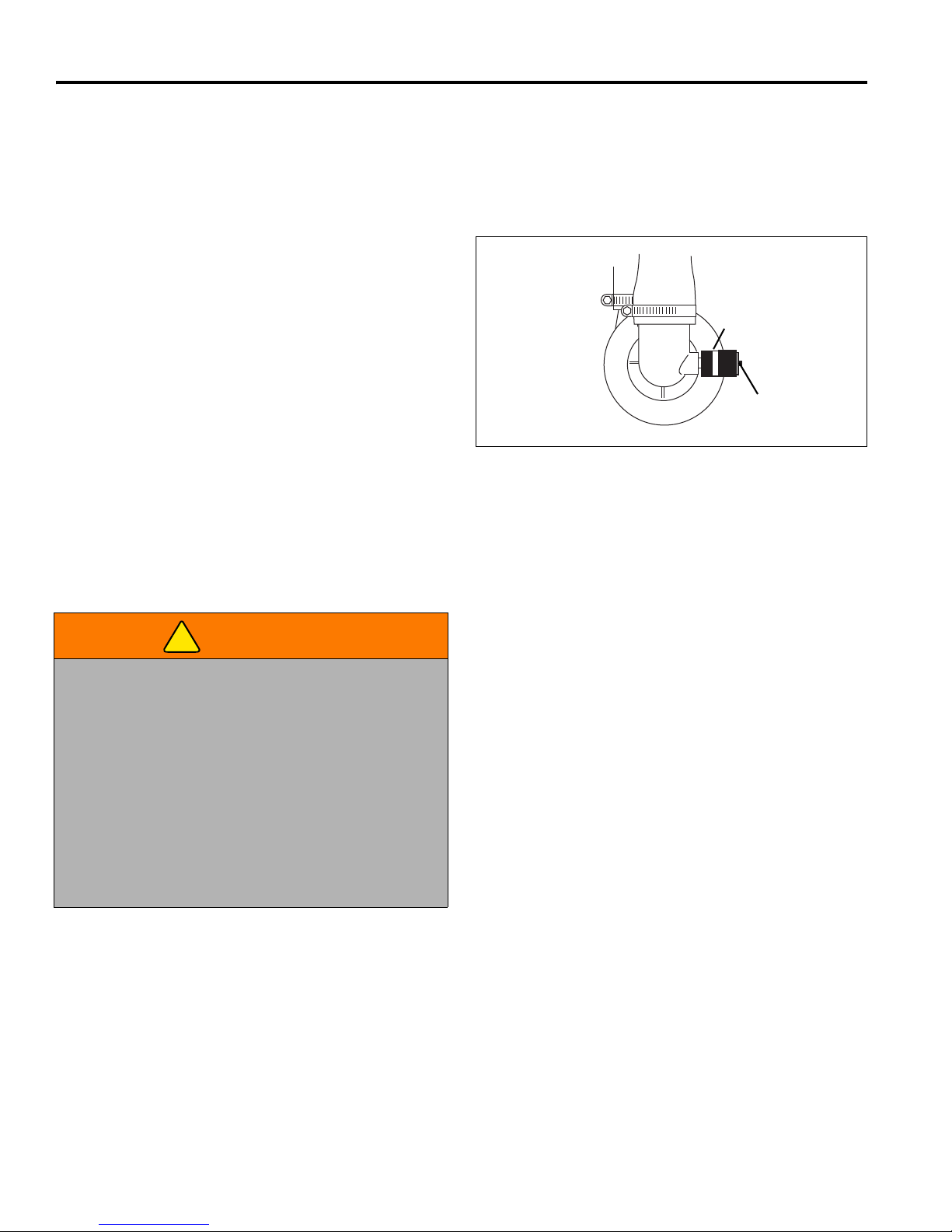
7 MAINTENANCE
A
B
!
7.4 AIR FILTER_______________________________________________________________
Check the service indicator daily. If red band appears in
the window (B) replace the element.
Do not remove the element for inspection or
cleaning. Unnecessary removal of the filter increases
the risk of injecting dust and other impurities into the
engine.
When service is required, first clean the outside of the
filter housing, then remove the old element as gently as
possible and discard.
1. Carefully clean the inside of the filter housing without
allowing dust into the air intake.
2. Inspect the new element. Do not use a damaged
element and never use an incorrect elem e nt .
3. Assemble the new element and make sure it seats
properly. Reset the indicator by depressing button
(A).
4. Reassemble cap making sure it seals completely
around the filter housing. Dust evacuator must be
facing down.
5. Check all hoses and air ducts. Tighten hose clamps.
Figure 7A
7.5 FUEL____________________________________________________________________
Handle fuel with care - it is highly flammable. Only
use an approved container. The spout must fit inside the
fuel filler neck. Avoid using cans and funnels to transfer
fuel.
WARNING
Never remove the fuel cap from the fuel tank, or add
fuel, when the engine is running or while the engine is
hot.
Do not smoke when handling fuel. Never fill or drain
the fuel tank indoors.
Fill the fuel tank to within 1 in. (2.5 cm) below the filler
neck.
Use clean, fresh, #2, low or ultra low sulfur Diesel fuel,
minimum Cetane Rating 45. Refer to Engine Manual for
additional information.
Check fuel lines and clamps every 50 hours. Replace fuel
lines and clamps at the first sign of damage.
Store fuel according to local, state or federal ordinances
and recommendations from your fuel supplier.
Never overfill or allow the tank to become empty.
Clean spilled fuel immediately.
Never handle or store fuel containers near an open
flame or any device that may create sparks and ignite
the fuel or fuel vapors.
Be sure to reinstall and tighten fuel cap securely.
7.6 FUEL SYSTEM ____________________________________________________________
Refer to Section 6.2 for specific maintenance intervals.
Before replacing any filter, thoroughly clean the filter
housing and the area around the filter. Dirt must not be
allowed to enter into fuel system.
Bleed the fuel system after the fuel filter and lines have
been removed, or the fuel tank has become empty. See
Engine Manual.
34
To change fuel filter:
1. Close fuel valve on tank, then remove and discard
the existing filter.
2. Apply a light coat of oil to the gasket and hand
tighten new filter.
3. Fill fuel tank. Open fuel valve on tank and bleed the
filter. See Engine Manual.
Page 35
MAINTENANCE 7
!
!
!
!
7.7 BATTERY ________________________________________________________________
Make absolutely certain the ignition switch is OFF
position and the key has been removed before servicing
the battery.
CAUTION
Always use insulated tools, wear protective glasses or
goggles and protective clothing when working with
batteries. You must read and obey all the battery
manufacturer’s instructions.
Tighten cables securely to battery terminals and apply a
light coat of silicone dielectric grease to terminals and
cable ends to prevent corrosion. Keep vent caps and
terminal covers in place.
Check the electrolyte level every 100 hours. Keep the
cable ends, battery and battery posts clean.
Always disconnect battery cables from battery and
controller connectors before performing and welding
operation on the mower.
Verify battery polarity before connecting or disconnecting
the battery cables.
1. When installing the battery, always assemble the
RED, positive (+) battery cable first and the ground,
BLACK, negative (-) cable last.
2. When removing the battery, always remove the
ground, BLACK, negative (-) cable first and the
RED, positive (+) cable last.
3. Make sure battery is properly installed and secured
to the battery tray.
WARNING
Battery posts, terminals, and related accessories
contain lead and lead compounds, chemicals known
to the State of California to cause cancer and other
reproductive harm. Wash your hands after
handling.
7.8 JUMP STARTING __________________________________________________________
Before attempting to “jump start” the mower, check the
condition of the discharged battery. Section 7.7.
WARNING
Batteries generate explosive hydrogen gas. To reduce
the chance of an explosion, avoid creating sparks
near battery. Always connect the negative jumper
cable to the frame of the mower with the discharged
battery, away from the battery.
When connecting jumper cables:
1. Stop the engine on vehicle with good battery.
2. Connect RED jumper cable to the positive (+)
terminal on the good battery and to the positive (+)
terminal on the “discharged” battery.
3. Connect the BLACK jumper cable from the negative
(-) terminal on the good battery to the frame of
mower with discharged battery.
After cables have been connected, start the engine on
the vehicle with the good battery then start the mower.
7.9 CHARGING BATTERY _____________________________________________________
WARNING
Charge battery in a well ventilated area. Batteries
generate explosive gases. To prevent an explosion,
keep any device that may create sparks or flames
away from the battery.
To prevent injury, stand away from battery when the
charger is turned on. A damaged battery could
explode.
1. Refer to Section 7.7. Read the Battery and
Charger’s manual for specific instructions.
2. Whenever possible, remove the battery from the
mower before charging. If battery is not sealed,
check that the electrolyte liquid covers the plates in
all the cells.
3. Make sure the charger is OFF, then connect the
charger to the battery terminals as specified in the
charger’s manual.
4. Always turn the charger OFF before disconnecting
charger from the battery terminals.
35
Page 36

7 MAINTENANCE
!
!
7.10 MUFFLER AND EXHAUST __________________________________________________
To protect from carbon monoxide poisoning, inspect th e
WARNING
Exhaust fumes contain carbon monoxide that is toxic
and can be fatal when inhaled.
NEVER operate an engine without proper ventilation.
7.11 HYDRAULIC HOSES _______________________________________________________
WARNING
To prevent serious injury from hot, high pressure oil,
never use your hands to check for oil leaks. Use paper
or cardboard.
Hydraulic fluid escaping under pressure can have
sufficient force to penetrate skin. If fluid is injected into
the skin it must be surgically removed within a few
hours by a doctor familiar with this form of injury or
gangrene may result.
1. Always lower implements to ground, disengage all
drives, engage parking brake, stop engine and
remove key before inspecting or disconnecting
hydraulic lines or hoses.
2. Check visible hoses and tubes daily. Look for wet
hoses or oil spots. Replace worn or damaged hoses
and tubes before operating the machine.
3. The replacement tube or hoses must be routed in
the same path as the existing hose. Do not move
clamps, brackets and ties to a new location.
complete exhaust system regular ly and always replace a
defective muffler.
If you notice a change in the color or sound of the
exhaust, stop the engine immediately. Identify the
problem and have the system repaired.
Torque all exhaust manifold hardware evenly. Tighten or
replace exhaust clamps.
4. Thoroughly inspect all tubes, hoses and connections
every 250 hours.
IMPORTANT: The hydraulic system can be
permanently damaged if the oil becomes
contaminated. Before disconnecting any hydraulic
component, clean the area around the fittings and the
hose ends to keep impurities out of the system.
a. Before disconnecting any hydraulic component,
tag or mark the location of each hose then clean
the area around the fittings.
b. As you disconnect the component, be prepared
to assemble plugs or caps to the hose ends and
open ports. This will keep impurities out of the
hydraulic system and also prevent oil spills.
c. Make sure “O” rings are clean and hose fittings
are properly seated before tightening.
d. Keep the hose from twistin g. Twisted hoses can
cause couplers to loosen as the hose flexes
during operation, resulting in oil leaks.
e. Kinked or twisted hoses can restrict the oil flow,
causing the system to malfunction and the oil to
overheat and also lead to hose failure.
7.12 HYDRAULIC OIL __________________________________________________________
Refer to Section 6.2 for specific maintenance intervals.
Drain and replace the hydraulic oil after a major
component failure, or if you notice the presence of water
or foam in the oil, or a rancid odor (indicating excessive
heat).
Always replace hydraulic filter when oil filter light stays on
or when changing oil.
To change hydraulic oil:
1. Clean the area around the oil cap to prevent
impurities from entering and contaminating the
system.
2. Remove drain plug from bottom of tank.
36
3. After oil has drained, install drain plug and fill with
hydraulic oil.
4. Purge air from system.
a. Operate all mower functions for about 5 minutes
to purge air out of the system and stabilize the oil
level. During this time, the oil level alarm may
sound.
b. Once the level has stabilized and the air is
purged, fill the tank to the full mark on dipstick.
Star t e ngi ne a nd ch eck th at oil al arm remain s o ff.
Page 37

MAINTENANCE 7
!
CIRCUIT BREAKER
CB1 50 A CIRCUIT BREAKER
FUSES
F1 20 A ALTERNATOR, GAUGES, SWITCHES
F2 20 A LIGHTS
RELAYS
K1 GLOW PLUG
K2 STARTER
7.13 HYDRAULIC FILTER _______________________________________________________
The hydraulic system is protected by a 10 micron return
line filter. Flow though the filters is monitored during
operation. When pressure drop across the filters is too
high the hydraulic oil filter warning light will come on. To
ensure continued protection to the hydraulic system,
replace filter as soon as possible after light comes on.
NOTICE
During cold weather the warning light may come on
until oil has warmed up to operating temperature. Wait
until oil has warmed up and light goes out before
operating mower.
To replace hydraulic filter:
1. Remove the old filter.
2. Install new filter. Hand tighten only.
3. Operate engine at idle speed with hydraulic system
in Neutral for five minutes. The oil level alarm may
sound during this time.
4. Check hydraulic oil level in reservoir and fill to full
mark on dipstick.
7.14 ELECTRICAL SYSTEM _____________________________________________________
CAUTION
Always turn the ignition switch OFF and remove the
negative battery cable (BLACK) before inspecting or
working on the electrical system.
General precautions that can be taken to reduce
electrical problems are listed below.
1. Make certain all terminals and connections are clean
and properly secured.
2. Check the interlock system, fuses and circuit
breakers regularly.
If the interlock does not function properly and the
problem cannot be corrected, contact an authorized
Jacobsen Dealer.
For factory assistance with troubleshooting controller
problems, please note the controller hardware
revision and software version located on the lower
right corner of the controller. Controllers with equal or
greater revision levels will be backward compatible.
Circuits are protected by a circuit breaker, fuses and
relays mounted on or near the controller.
NOTICE
3. Keep the wire harness and all individual wires away
from moving parts to prevent damage.
4. Make sure the seat switch harness is connected to
the main wire harness.
5. Check the battery and battery charging circuit.
6. Do not wash or pressure spray around electrical
connections and components.
The electrical system is monitored and controlled by the
electronic controller (C) located behind the operator’s
area. The controller is equipped with two banks of LED’s
which can be used when troubleshooting the electrical
system. See Section 9.2.
Figure 7B
37
Page 38
7 MAINTENANCE
!
!
!
!
7.15 RADIATOR _______________________________________________________________
Mix clean water with ethylene glycol based anti-freeze for
WARNING
To prevent serious bodily injury from hot coolant or
steam blow-out, never attempt to remove the radiator
cap while the engine is running. Stop the engine and
wait until it is cool. Even then, use extreme care when
removing the cap.
the coldest ambient temperature. Read and follow the
instructions on the anti-freeze container and Engine
Manual.
Keep radiator and hydraulic oil cooler air passages clean.
Use compressed air (30 psi maximum) to clean the fins.
To clean radiator:
1. Use a blow gun to clean the radiator and oil cooler
fins.
CAUTION
Do not pour cold water into a hot radiator. Do not
operate engine without a proper coolant mixture.
Install cap and tighten securely.
Check coolant level daily. Radiator should be full and
recovery bottle should be up to the cold mark.
Drain and refill annually. Remove the radiator cap, open
the engine block drain and the radiator drain. Empty and
clean the recovery bottle.
A sliding panel located under the frame can be
loosened and pulled back to allow dirt and debris to
fall through frame.
2. Check and tighten the fan belt. Replace clamps and
hoses every two years.
3. If you have to add coolant more than once a month,
or add more than one quart at a time, have a
Jacobsen Dealer check the cooling system.
NOTICE
7.16 ROLL OVER PROTECTIVE STRUCTURE (ROPS)________________________________
A Roll Over Protective Structure (ROPS), designed for
this mower, is included with this mower as standard
equipment. Inspect it periodically and follow operating
procedures.
CAUTION
Do not loosen or remove bolts, do not weld, drill,
modify, bend, or straighten a damaged structure.
1. The seat, the seat belt, mounting hardware, and any
accessories within the ROPS, should be inspected
regularly and all damaged parts replaced
immediately.
2. Once the ROPS has been subjected to any form of
impact it should be replaced.
3. Check and re-torque all hardware. All replacement
components used for the ROPS must be as
specified in the Parts Catalog.
7.17 TIRES ___________________________________________________________________
1. Keep tires properly inflated to prolong tire life. Check
inflation pressure while the tires are cool. Inspect
tread wear.
2. Check pressure every 50 hours or once a month.
Use an accurate, low pressure tire gauge.
3. Keep tires inflated to:
Front - 16 psi (1.11 BAR)
Rear - 12 psi (0.86 BAR)
Unless you have the proper training, tools and
experience, DO NOT attempt to mount a tire on a rim.
Improper mounting can produce an explosion which
may result in serious injury.
CAUTION
38
Page 39
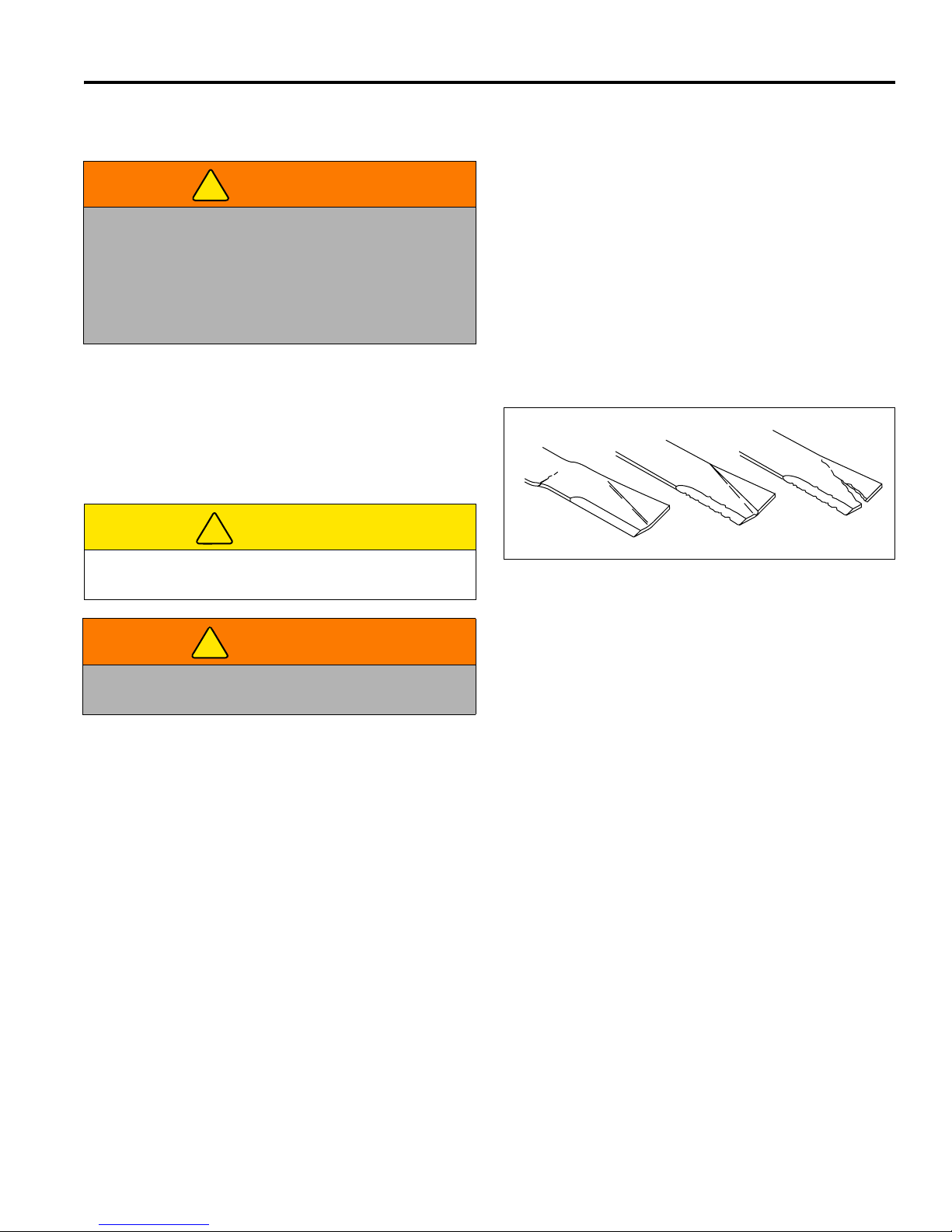
MAINTENANCE 7
!
!
!
G
H
J
HR025
7.18 WHEEL MOUNTING PROCEDURE ____________________________________________
1. Remove dirt, grease and oil from stud thread. Do not
lubricate threads.
WARNING
Make sure the mower is parked on a solid and level
surface. Never work on a mower that is supported
only by the jack. Always use jack stands.
If only the front or rear of the mower is raised, place
chocks in front of and behind the wheels that are not
raised.
7.19 INSPECTING BLADES ______________________________________________________
1. Every 50 hours of operation or whenever mower is
removed from mower, carefully examine the blades
to make sure they are in good operating condition.
Blades showing any bends (G), grooves (H) or
cracks (J) must be replaced.
2. Position wheel on hub and inspect to insure full
contact between mounting surface of wheel and hub
or brake drum.
3. Finger tighten all hardware, then torque hardware in
criss-cross order; always tighten nuts in the top
position.
4. Check and re-torque daily until torque is maintained
at 85-95 ft.lbs. (115-128 Nm).
CAUTION
Use care when checking blades to avoid pinching
hands and fingers between blade ends.
WARNING
Never attempt to straighten, weld, or repair a
damaged blade. Always replace a damaged blade.
2. Any of the above conditions can cause a piece of
the blade to break away and be hurled from the
mower, causing very serious injury to bystanders or
property damage.
3. A bent blade could have a microscopic crack (G)
that can grow and allow a piece of the blade to
break. Bent blades will also create vibration and
other stress on the machinery.
4. Dust or sand particles can wear a dangerous groove
in the blade (H) between the air vanes and the flat
portion of the blade that will rapidly grow and
produce a crack (J), permitting a piece of the vane
to break off.
Figure 7C
39
Page 40
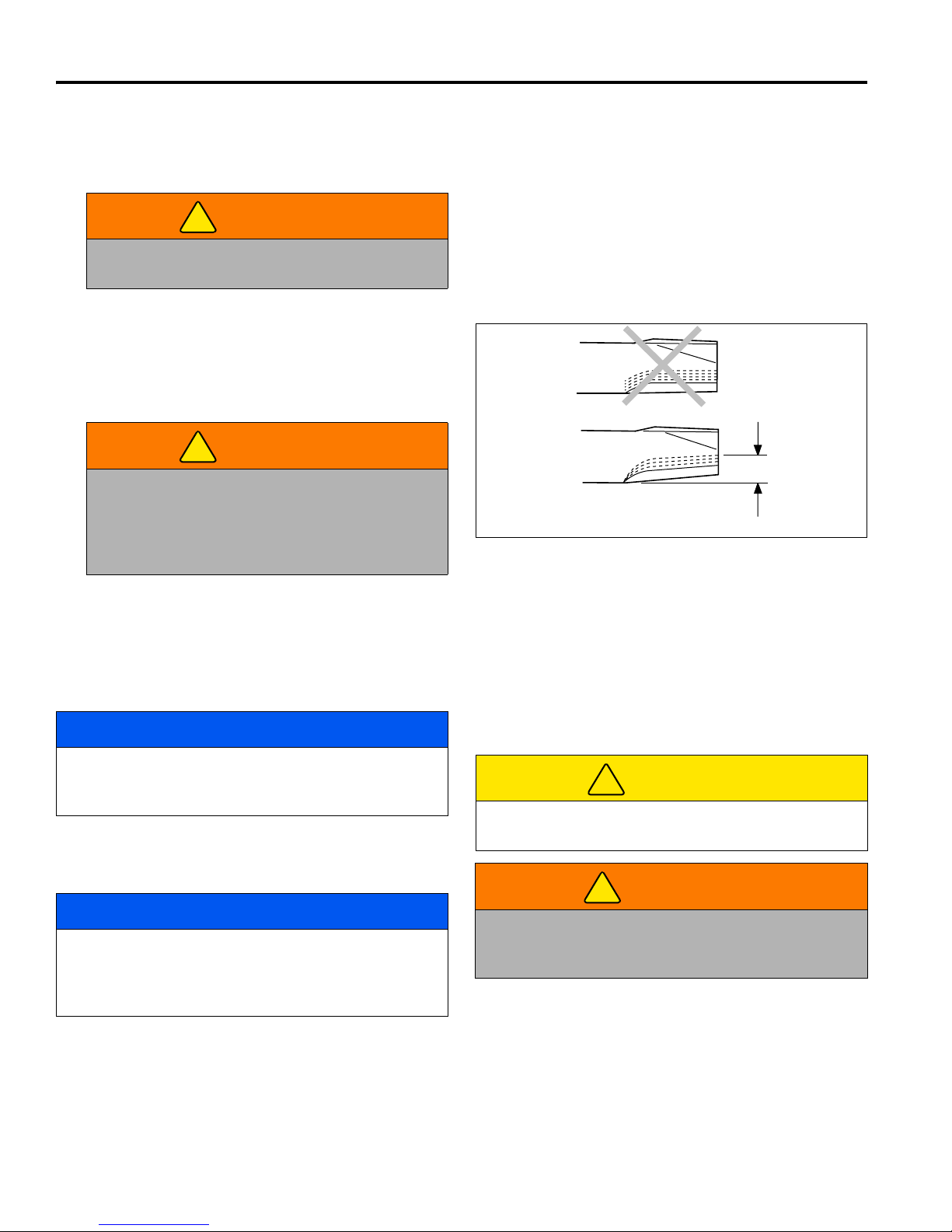
7 MAINTENANCE
!
!
A
B
1/2 in. (1.3 cm)
Maximum
HR024
!
!
7.20 SHARPENING BLADES_____________________________________________________
1. Place a wooden block between the blade and mower
housing to stop the blade from moving.
WARNING
The mower blades can develop sharp edges. Use
caution whenever servicing and handlin g.
2. When dressing or sharpening the blade, do not
follow the original pattern of grind as shown in (A).
Grind new cutting edges at an angle as shown in
(B).
If the maximum total loss of the blade reaches 1/2 in.,
(1.3 cm), do not sharpen further. Replace blade.
3. Make sure an equal amount of material is removed
from both sides of blade to prevent having an
unbalanced blade. An unbalanced blade will cause
excessive vibration and may damage the mower.
4. Use a blade balancer to check the blade after
sharpening.
5. Torque center mounting screw holding blade to 75
to 90 ft. lb. (100 to 120 Nm).
WARNING
Re-sharpening the blade beyond the allowable
1/2 in. (1.3 cm) may allow the blade tip to break
off and be thrown from the mower. Such an
incident can cause very serious injury to
bystanders and/or property damage.
7.21 CARE AND CLEANING _____________________________________________________
Figure 7D
Clean the mower and implements after each use. Keep
the equipment clean. Do not wash equipment with engine
running. Serious engine damage may result. Whenever
possible, clean the equipment using compressed air.
NOTICE
Do not wash any portion of the equipment while it is
hot. Do not use high pressure spray or steam. Use
cold water and automotive cleaners.
1. Use compressed air to clean engine and radiator
fins.
2. Use only fresh water when washing your equipment.
NOTICE
Use of salt water or effluent water has been known to
encourage rust and corrosion of metal parts, resulting
in premature deterioration or failure. Damage of this
nature is not covered by the factory warranty.
3. Do not spray water directly at the instrument panel,
ignition switch, controller or any other electrical
components, or at bearing housings and seals.
4. Clean all plastic or rubber trim with a mild soap
solution or use commercially available vinyl/rubber
cleaners.
40
5. To maintain the original high luster of the fiberglass,
periodically wax with a good grade of One-Step
cleaner wax.
Repair damaged metal surfaces and use Jacobsen
touch-up paint. Wax the equipment for maximum paint
protection.
CAUTION
Clean grass and debris from cutting units, drives,
muffler and engine to prevent fires.
WARNING
NEVER use your hands to clean cutting units. Use a
brush to remove grass clippings from blades. Blades
are extremely sharp and can cause serious injuries.
Page 41

MAINTENANCE 7
!
!
7.22 STORAGE________________________________________________________________
General
1. Wash the mower thoroughly and lubricate. Repair
and paint damaged or exposed metal.
2. Inspect the mower, tighten all hardware, replace
worn or damaged components.
3. Drain and refill radiator.
4. Clean the tires thoroughly and store the mower so
the load is off the tires. If mower is not on jack
stands, check tires at regular intervals and re-inflate
as necessary.
5. Keep the machine and all its accessories clea n, dry
and protected from the elements during storage.
Never store equipment near an open flame or spark
which could ignite fuel or fuel vapors.
Battery
1. Remove, clean and store battery in upright position
on a non-conductive surface (wood) in a cool, dry
place. To prevent accelerated discharge, do not store
battery on concrete or steel surface.
2. Check and recharge battery every 60 to 90 days
while in storage.
3. Store batteries in a cool, dry place. To reduce the
self discharge rate, room temperature should not be
above 80°F (27°C) or fall below 20°F (-7°C) to
prevent electrolyte from freezing.
Engine
1. While the engine is warm, remove drain plug, drain
the oil from the crankcase, and change oil filter.
Install drain plug and refill with fresh oil. Torque drain
plug to 22 ft. lb. (30 Nm).
2. Clean exterior of engine. Paint exposed metal or
apply a light coat of rust preventative oil.
3. Add a fuel conditioner or biocide to prevent gelling
or bacterial growth in fuel. See your local fuel
supplier.
Cutting Units
1. Wash the cutting units thoroughly, then repair and
paint any damaged or exposed metal.
2. Lubricate all fittings and friction points.
3. Apply a light coat of rust preventative oil to the
sharpened edges of the blades.
After Storage
1. Check and reinstall battery
2. Check or service fuel filter and air cleaner.
3. Check the radiator coolant level.
4. Check oil level in the engine crankcase and
hydraulic system.
5. Fill the fuel tank with fresh fuel. Bleed the fuel
system.
6. Make certain that the tires are properly inflated.
7. Remove all oil from the blades. Adjust cutting
height.
8.
Start and operate the engine at 1/2 throttle. Allow
enough time for the engine to become properly
warmed and lubricated.
WARNING
Never operate the engine without proper ventilation,
exhaust fumes can be fatal when inhaled.
CAUTION
To prevent personal injury and damage to the cutting
edges, handle the blades with extreme care.
41
Page 42
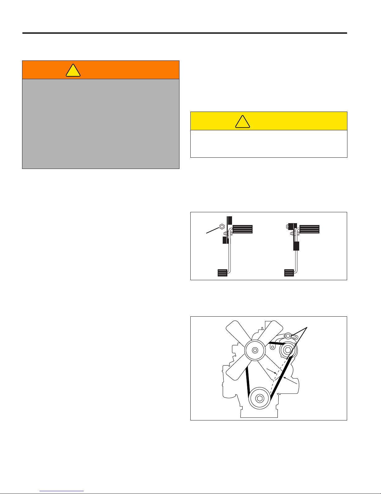
8 ADJUSTMENTS
!
!
A
LF002
1/4 TO 5/16 IN.
(0.6 TO 0.8 CM)
B
LF012
8 ADJUSTMENTS
8.1 GENERAL________________________________________________________________
adjustment cannot be made, contact an authorized
WARNING
To prevent injury, lower implements to the ground,
disengage all drives, engage parking brake, stop
engine and remove key from ignition switch before
making any adjustments or performing maintenance.
Jacobsen Dealer.
2. Replace, do not adjust, worn or damaged
components.
3. Do not wear jewelry or loose fitting clothing when
making adjustments or repairs.
Make sure the mower is parked on a solid and level
surface. Never work on a mower that is supported
only by the jack. Always use jack stands.
If only the front or rear of the mower is raised, place
chocks in front of and behind the wheels that are not
raised.
1. Adjustments and maintenance should always be
performed by a qualified technician. If proper
Be careful to prevent entrapment of the hands and
fingers between moving and fixed components of the
machine.
4. Do not change governor settings or over speed the
engine.
CAUTION
8.2 MOW SPEED _____________________________________________________________
Cutting quality is better at speeds well below the
transport speed of the mower. An initial mow speed of
five to six mph is set at the factory and should be
satisfactory for most cutting conditions. Local turf
conditions, however, may respond better to a different
speed.
To set mow speed, loosen jam nut (A) and adjust stop
screw up to reduce speed, down to increase speed.
Tighten nut to hold adjustment in place.
Figure 8A
8.3 BELT____________________________________________________________________
Inspect and adjust new belt after first ten hours of
operation. Adjust every 100 hours thereafter.
Adjust alternator pulley so belt deflects 1/4 to 5/16 in. (0.6
- 0.8 cm) with a 20 lb. push at midpoint between pulleys.
See Engine manual.
If tension is incorrect, loosen alternator mounting bolts
(B) and adjust alternator until proper belt tension is
achieved.
42
Figure 8B
Page 43
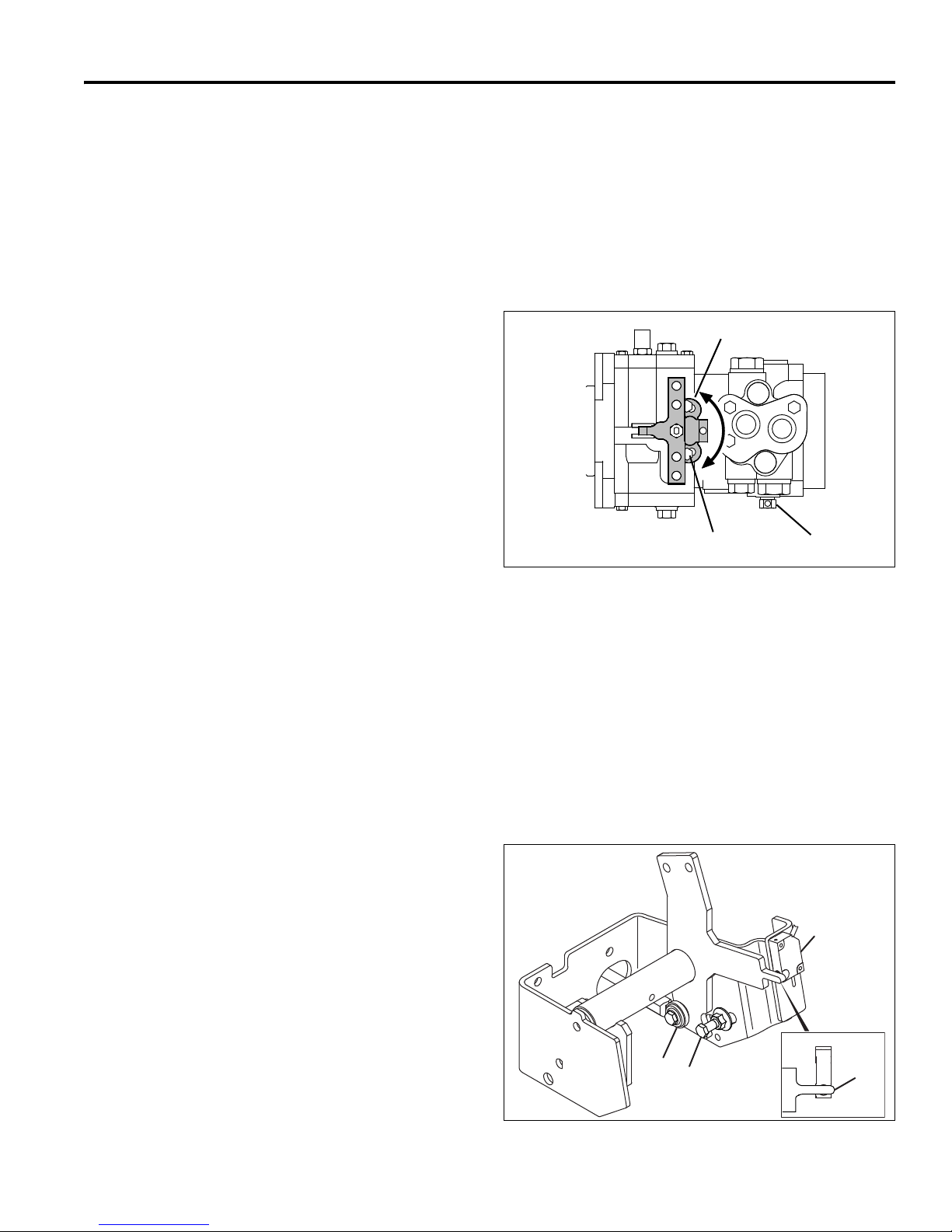
ADJUSTMENTS 8
F
H
G
LF014
J
K
L
M
8.4 NEUTRAL ADJUSTMENT ___________________________________________________
Neutral adjustment can only be made at the drive pump.
The Neutral adjustment is preset at the factory on all new
mowers and replacement pumps. Further adjustment is
not required unless the pump has been disassembled for
repair or service.
To adjust Neutral:
1. Disconnect traction pedal linkage from pump.
2. Place mower securely on jack stands so All wheels
are raised off ground.
3. Check that tow valve (H) is closed
4. Engage parking brake and set mow switc h to OFF.
Make sure Neutral switch at traction pedal is closed.
(Figure 8D - M). Distance between the sensing
portion of switch and metal pointer (M) must be
between 1/16 and 1/8 in. (0.15 and 0.3 cm).
5. Loosen screws (G) holding pump lever bracket just
enough so it can be moved. Start engine, disengage
parking brake, and observe wheels. Adjust bracket
(F) in slotted holes until wheels do not turn . Turn off
engine and tighten bracket in place.
6. Connect traction linkage. When connecting linkage
at traction pedal make sure pointer on traction pedal
bracket is centered over Neutral switch (M -Figure
8D).
7. Start engine and check operation of traction pedal.
Wheels must not turn when pedal returns to Neutral
and lamp 5 on controller should light, see Section
9.2.
Figure 8C
8.5 FORWARD / REVERSE SPEED ______________________________________________
Forward and reverse speeds are adjusted at the traction
pedal. Set forward speed before adjusting reverse.
To adjust forward speed:
1. Make sure drive pump has been set to Neutral and
engine throttle is adjusted correctly. Rotate the
traction pedal mow speed stop to the transport
position.
2. Start engine and check forward travel speed with
engine at full throttle. Forward transport speed
should measure 12 mph (19.3 kph).
3. Stop engine. To adjust forward speed, disconnect
eye bolt (K) from pedal and loosen jam nut. Turn
eye bolt in to reduce speed, ou t to increase speed.
Tighten jam nut to hold adjustment in place and
connect eye bolt.
4. With traction pedal in Neutral, check position of
Neutral switch (J). Adjust switch up or down so
pointer (M) on traction pedal bracket is centered
over it. When adjusted correctly lamp 5 on controller
will light when ignition switch is turned to on.
5. Start engine and check forward speed. Repeat
procedure until 12 mph (19.3 kph) forward transport
speed is attained.
To adjust reverse speed:
1. Set forward speed.
2. Start engine and check reverse travel speed with
engine at full throttle. Reverse speed should
measure 5 mph (8 kph).
3. Stop engine. To adjust reverse speed, loosen nut on
reverse travel stop bolt (L). Slide bolt forward in
slotted hole to increase speed, back to reduce
speed. Tighten nut to hold adjus tment in place.
4. Start engine and check speed. Repeat procedure
until 5 mph (8 kph) reverse speed is attained.
Figure 8D
43
Page 44
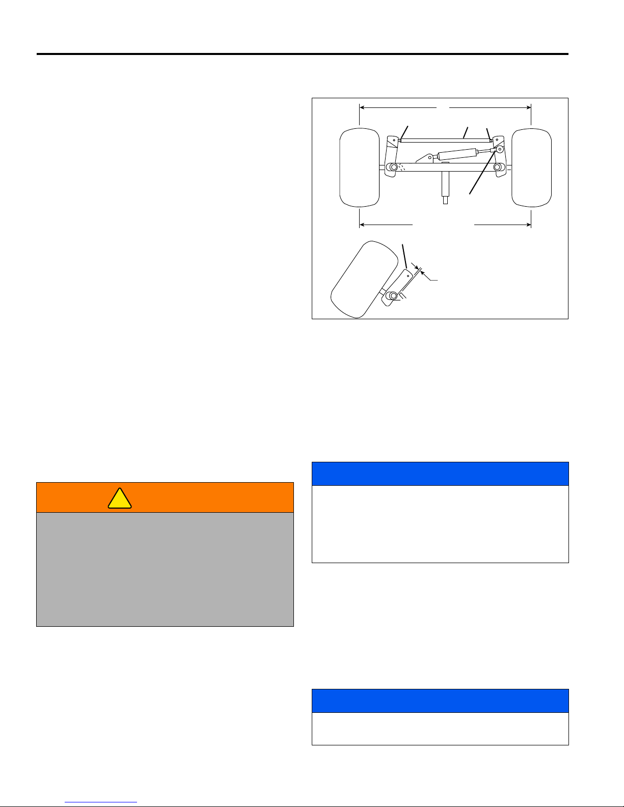
8 ADJUSTMENTS
3/4 ± 1/16 in.
(1.9 ± 0.15 cm)
N
S
T
U
P
P +0 to1/16”
R
(+0 to 0.15 cm)
N
!
8.6 STEERING TOE-IN_________________________________________________________
1. Turn wheels to straight ahead position.
2. Loosen jam nuts (N) on both sides of tie rod (M).
3. Turn tie rod (S) to provide proper toe-in. Toe-in must
not exceed +1/16 in. (+0.15 cm) (P). Re tighten jam
nuts.
4. After adjusting tie rod, adjust steering cylinder by
threading the rod (T) in or out of ball joint so spindle
arm (R) clears the st op on the axle by 3/4 ± 1/16 in.
(1.9 ± 0.15 cm) (U) when cylinder is fully extended.
Figure 8E
8.7 TRACTION CONTROL SYSTEM CALIBRATION _________________________________
The Traction Control System (TCS) will need to be
calibrated when a system component has been replaced
or the system is not working correctly. System
components include controller, lift valve, lift cylinders, or
hoses.
1. Allow hydraulic system to become properly warmed
up. An operator must be in the seat during the
calibration procedure.
WARNING
Never operate the engine without proper ventilation;
exhaust fumes can be fatal when inhaled.
While warming up the hydraulic system for the
calibration procedure, the cutting unit blades will be
turning. Make certain that the area under and around
the cutting units is clean and any debris that can be
thrown from the machine is cleared away. Keep
bystanders away from unit.
a. Start engine and move throttle to full position.
b. Release the parking brake.
c. Turn PTO switch ON.
d. Fully lower cutting units to the ground.
e. Engage traction control system.
f. Allow unit to run for 5 minutes with these set-
2. System must be calibrated with the engine running,
operator in seat, PTO switch in OFF position,
tings.
44
parking brake switch ON and traction pedal in
Neutral.
3. Fully lower cutting units. Verify all five decks are all
the way down.
4. Press and hold TCS switch for 5 seconds. Horn will
beep when controller enters calibration mode.
NOTICE
Do not release switch until horn stops for both starting
and finishing the calibration procedure.
Do not rush through steps 5 and 6. System will not be
properly calibrated if decks do not start to raise in step
5 and are not fully lowered during step 6.
5. Tap the lift lever to raise position and wait for 3 to 5
seconds. Repeat if required until cutting units just
begin to raise.
6. Tap the lift lever to lower position and wait until
decks stop moving. Repeat, tapping joystick if
required until front decks are on the ground.
7. Press and hold TCS switch until horn beeps.
System is now calibrated.
NOTICE
To cancel calibration mode, turn keyswitch to the OFF
position.
Page 45
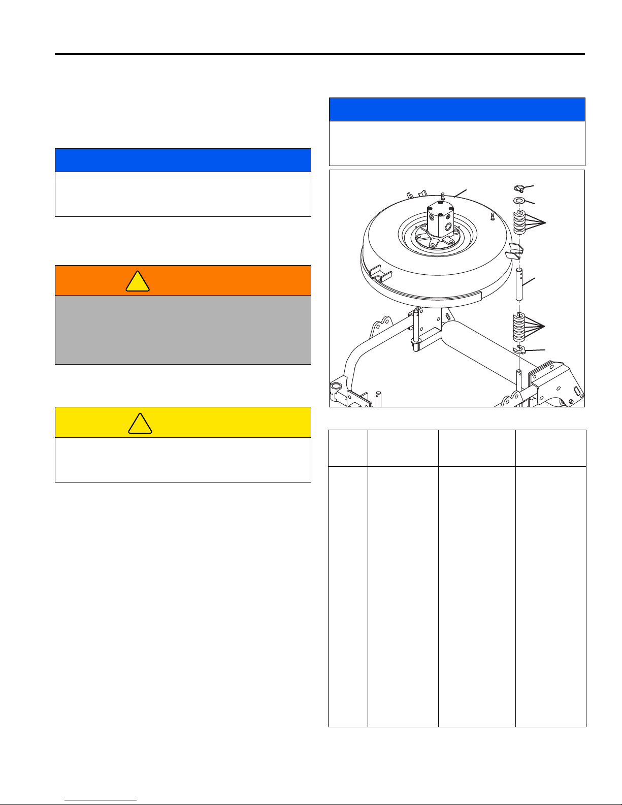
ADJUSTMENTS 8
!
!
E
F
D
B
A
C
D
8.8 CUTTING HEIGHT _________________________________________________________
Cutting height for decks can be adjusted from 3/4 to 5-1/4
in. (1.9-13.3 cm) in 1/4 in. (0.6 cm) increments. Actual
cutting height may vary somewhat from the heights given
depending on turf conditions and other factors.
NOTICE
When cutting undulating areas, lower cutting heights
may cause scalping. Adjust height accordingly to
prevent turf damage.
1. Park the mower on a flat, level surface. Fully lower
cutting units. Stop engine and remove key from
ignition.
For best quality of cut, always place the same number
of spacers under deck housing on all three spindles.
Adjust all decks to same cutting height.
NOTICE
WARNING
To prevent serious injury, lower deck until it is resting
completely on the front casters and rear roller. This
will prevent it from accidentally lowering while making
adjustments. Disengage all drives, engage parking
brake, stop engine, and remove ignition key.
2. Refer to the chart provided for desired cutting
height.
CAUTION
Use proper lifting techniques when lifting or lowering
deck housings. The deck housing assemblies weigh
approximately 50 lbs (23 kg).
3. To lower height of cut, remove all three snap lock
pins (A). Lift outer spindle shaft (B) slightly and
remove 1/2 in. (1.3 cm) spacers (D) and/or 1/4 in
(0.6 cm) spacer (E) from bottom one at a time until
desired height is obtained. Carefully remove blocks
and lower deck housings (C). Place remaining
spacers on top of spindle and insert snap lock pins.
Washer (F) is always on top, under snap lock pin.
4. To raise height of cut, remove all three snap lock
pins (A). Carefully lift deck housing (C) above
desired cutting height and support with blocks. Add
1/2 in. (1.3 cm) spacers (D) and/or 1/4 in. (0.6 cm)
spacer (E) as required until desired height is
obtained. Lower deck housing. Place remaining
spacers on top of spindle and insert snap lock pins.
Washer (F) is always on top, under snap lock pin.
Figure 8F
Height
of
Cut
3/4 0 9 Above Housing
1-1/4 1 8 Above Housing
1-1/2 1 8 Below Housing
1-3/4 2 7 Above Housing
2-1/4 3 6 Above Housing
2-1/2 3 6 Below Housing
2-3/4 4 5 Above Housing
3-1/4 5 4 Above Housing
3-1/2 5 4 Below Housing
3-3/4 6 3 Above Housing
4-1/4 7 2 Above Housing
4-1/2 7 2 Below Housing
4-3/4 8 1 Above Housing
5-1/4 9 0 Above Housing
1/2” Spacers
Below Mower
Housing
1 0 9 Below Housing
2 2 7 Below Housing
3 4 5 Below Housing
4 6 3 Below Housing
5 8 1 Below Housing
1/2” Spacers
Above Mower
Housing
1/4” Spacer
Location
45
Page 46
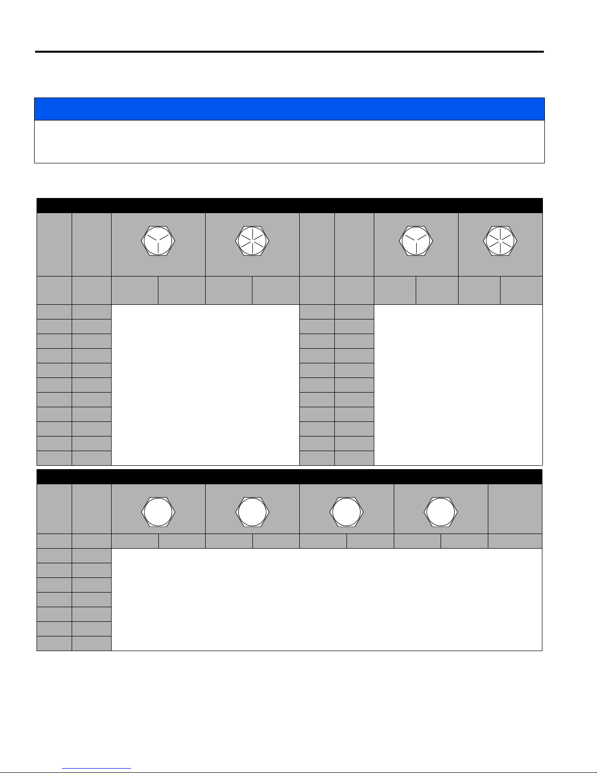
8 ADJUSTMENTS
4.6
8.8
10.9
12.9
8.9 TORQUE SPECIFICATION___________________________________________________
NOTICE
All torque values included in these charts are approximate and are for reference only. Use of these torque values is
at your sole risk. Jacobsen is not responsible for any loss, claim, or damage arising from the use of these charts.
Extreme caution should always be used when using any torque value.
Jacobsen uses Grade 5 Plated bolts as standard, unless otherwise noted. For tightening plated bolts, use the value
given for lubricated.
AMERICAN NATIONAL STANDARD FASTENERS
SIZE UNITS
SIZE UNITS
GRADE 5 GRADE 8
Lubricated Dry Lubricated Dry Lubri-
#6-32 in-lb (Nm) – 20 (2.3) – – 7/16-14 ft-lb (Nm) 37 (50.1) 50 (67.8) 53 (71.8) 70 (94.9)
#8-32 in-lb (Nm) – 24 (2.7) – 30 (3.4) 7/16-20 ft-lb (Nm) 42 (56.9) 55 (74.6) 59 (80.0) 78 (105)
#10-24 in-lb (Nm) – 35 (4.0) – 45 (5.1) 1/2-13 ft-lb (Nm) 57 (77.2) 75 (101) 80 (108) 107 (145)
#10-32 in-lb (Nm) – 40 (4.5) – 50 (5.7) 1/2-20 ft-lb (Nm) 64 (86.7) 85 (115) 90 (122) 120 (162)
#12-24 in-lb (Nm) – 50 (5.7) – 65 (7.3) 9/16-12 ft-lb (Nm) 82 (111) 109 (148) 115 (156) 154 (209)
1/4-20 in-lb (Nm) 75 (8.4) 100 (11.3) 107 (12.1) 143 (16.1) 9/16-18 ft-lb (Nm) 92 (124) 122 (165) 129 (174) 172 (233)
1/4-28 in-lb (Nm) 85 (9.6) 115 (13.0) 120 (13.5) 163 (18.4) 5/8-11 ft-lb (Nm) 113 (153) 151 (204) 159 (215) 211 (286)
5/16-18 in-lb (Nm) 157 (17.7) 210 (23.7) 220 (24.8) 305 (34.4) 5/8-18 ft-lb (Nm) 128 (173) 170 (230) 180 (244) 240 (325)
5/16-24 in-lb (Nm) 173 (19.5) 230 (26.0) 245 (27.6) 325 (36.7) 3/4-10 ft-lb (Nm) 200 (271) 266 (360) 282 (382) 376 (509)
3/8-16 ft-lb (Nm) 23 (31.1) 31 (42.0) 32 (43.3) 44 (59.6) 3/4-16 ft-lb (Nm) 223 (302) 298 404 315 (427) 420 (569)
3/8-24 ft-lb (Nm) 26 (35.2) 35 (47.4) 37 (50.1) 50 (67.8) 7/8-14 ft-lb (Nm) 355 (481) 473 (641) 500 (678) 668 (905)
METRIC FASTENERS
SIZE UNITS Non Critical
Lubricated Dry Lubricated Dry Lubricated Dry Lubricated Dry
M4 Nm (in-lb)––––––3.83 (34)5.11 (45)2.0 (18)
M5 Nm (in-lb) 1.80 (16) 2.40 (21) 4.63 (41) 6.18 (54) 6.63 (59) 8.84 (78) 7.75 (68) 10.3 (910 4.0 (35)
M6 Nm (in-lb) 3.05 (27) 4.07 (36) 7.87 (69) 10.5 (93) 11.3 (102) 15.0 (133) 13.2 (117) 17.6 (156) 6.8 (60)
M8 Nm (in-lb) 7.41 (65) 9.98 (88) 19.1 (69) 25.5 (226) 27.3 (241) 36.5 (323) 32.0 (283) 42.6 (377) 17.0 (150)
M10 Nm (ft-lb) 14.7 (11) 19.6 (14) 37.8 (29) 50.5 (37) 54.1 (40) 72.2 (53) 63.3 (46) 84.4 (62) 33.9 (25)
M12 Nm (ft-lb) 25.6 (19) 34.1 (25) 66.0 (48) 88.0 (65) 94.5 (70) 125 (92) 110 (81) 147 (108) 61.0 (45)
M14 Nm (ft-lb) 40.8 (30) 54.3 (40) 105 (77) 140 (103) 150 (110) 200 (147) 175 (129) 234 (172) 94.9 (70)
GRADE 5 GRADE 8
Dry Lubri-
cated
cated
Dry
Fasteners into
Aluminum
46
Page 47

PROBLEM SOLVING 9
9 PROBLEM SOLVING
9.1 GENERAL ________________________________________________________________
The problem solving chart below lists basic problems that
may occur during start-up and operation. For more
Symptoms Possible Causes Action
Engine will not start. 1. Parking brake switc h OFF, traction
pedal not in Neutral, or mow switch
ON.
2. Glow plug has not timed out. 2. Reset ignition switch and allow glow plug to
3. Battery low on charge or defective. 3. Inspect condition of battery and battery
4. Fuel tank empty or dirty. 4. Fill with fresh fuel. Change fuel filter. Bleed fuel
5. Fuse blown. 5. Replace fuse.
6. Relay defective. 6. Test and replace relay.
7. Neutral switch on traction pedal
out of adjustment or defective.
Engine hard to start
or runs poorly.
Engine stops. 1. Fuel tank empty. 1. Fill with fresh fuel and bleed fuel lines.
Engine overheating. 1. Coolant level low. 1. Inspect and add coolant.
Battery not holding
charge.
Battery light on. 2. Low electrolyte. 2. Refill to correct level.
Decks cut unevenly. 1. Height of Cut not adjusted
1. Fuel level low, fuel or fuel filter dirty. 1. Fill with fresh fuel. Change fuel filter. Bleed fuel
2. Air cleaner dirty. 2. Inspect and replace air filter.
3. Injectors, fuel pump. 3. See Engine Manual.
4. Engine problem. 4. See Engine Manual.
2. Interlocks not set before leaving
operator’s seat.
2. Air intake restricted. 2. Clean air intake at radiator.
3. Water pump belt broken or loose. 3. Tighten or replace belt.
1. Loose or corroded battery
terminals.
3. Alternator belt loose or broken. 3. Tighten or replace belt.
4. Charging system defective. 4. See Engine Manual.
correctly.
2. Engine speed too low. Check engine speed. Run engine at full throttle.
3. Mow speed not adjusted for turf
conditions.
detailed information regarding the hydraulic an d electrica l
systems contact your area Jacobsen Dealer.
1. Check interlock system and start-up procedure.
time out before cranking engine.
connections.
lines.
7. Adjust or replace switch.
lines.
2. Turn parking brake switch ON and set mow
switch to OFF.
1. Inspect and clean terminals.
Inspect height of cut adjustment. Same number of
spacers below deck housing on all spindles.
Adjust mow speed for best cut.
47
Page 48

9 PROBLEM SOLVING
Lamp
2356891112141517
18
1920212223242526272829
30
32
33
INPUTS OUTPUTS
9.2 CONTROLLER LAMPS _____________________________________________________
The controller is a solid state device that monitors and
controls electrical functions. The controller receives input
signals from various switches and sensors throughout
the machine and transmits output signals to operate
example, to start the mower the Mow Switch must be
OFF (lamp 8 off) while the Neutral Start Switch (lamp 12),
Brake Switch (lamp 6) and Fuel Valve Hold Coil (lamp 27)
must be ON.
relays, solenoids and warning lights. It controls and
resets timers and contains built in logic to control certain
machine functions.
Each input and output signal is displayed through lamps
located on top of the controller. A closed input switch
indicates an active circuit and will turn an input lamp on.
An open switch an inactive circuit and will turn a lamp off.
Outputs are active when their lights are on.
For factory assistance with troubleshooting controller
problems, please note the controller hardware
revision and software version located on the lower
right corner of the controller. [SEE 7.14] Controllers
with equal or greater revision levels will be backward
compatible.
NOTICE
It is important to note that in some cases a lamp or group
of lamps must be on or off for a condition to be true. For
Controller Functions by Lamp Number
Lamp On - Circuit is active
Lamp Off - Circuit is inactive
INPUTS OUTPUTS
Lamp Circuit Lamp Circuit
1,2,3,4
5
6
7
8
9
10
11
12
13
14
15
16
17
18
Program Select (1, 3 and 4 are not used)
Brake Switch
Seat Switch
Traction Control Switch
Mow Switch
Joystick - Lower
Joystick - Raise
Hydraulic Oil Level Switch
Neutral Switch
Not Used
Keyswitch - Glowplug
Keyswitch - Start
Joystick Active
Hydraulic Filter Switch
Engine Oil Pressure Switch
19 Hydraulic Filter Light
20 Hydraulic Oil Level Light
21 Not Used
22 Glowplug Light
23 Lower Solenoid
24 Raise Solenoid
25 Glowplug Relay
26 Start Relay
27 Fuel Solenoid - Hold
28 Not Used
29 Audible Alarm
30 Mow Solenoid
31 Fuel Solenoid - Pull
32 Power-Ignition
33 Power-Lights
48
Page 49

PROBLEM SOLVING 9
9.3 ELECTRICAL CIRCUITS ____________________________________________________
When troubleshooting the mower using the controller
always check that Program Select (2) lamp is on. This
indicates that the controller has power and the program is
active.
NOTICE
The controller requires a minimum of six volts to
operate.
Individual circuits can be tested by operating an input
switch, checking for the required input signal and looking
for a corresponding output. Keep in mind that not all
switches are located on the instrument panel. The
traction pedal and reel lift limit are controlled by small
proximity switches mounted on the frame of the mower.
If an input lamp does not light, an inactive condition is
indicated. This could be caused by a fuse, faulty switch
or poor connection.
49
Page 50
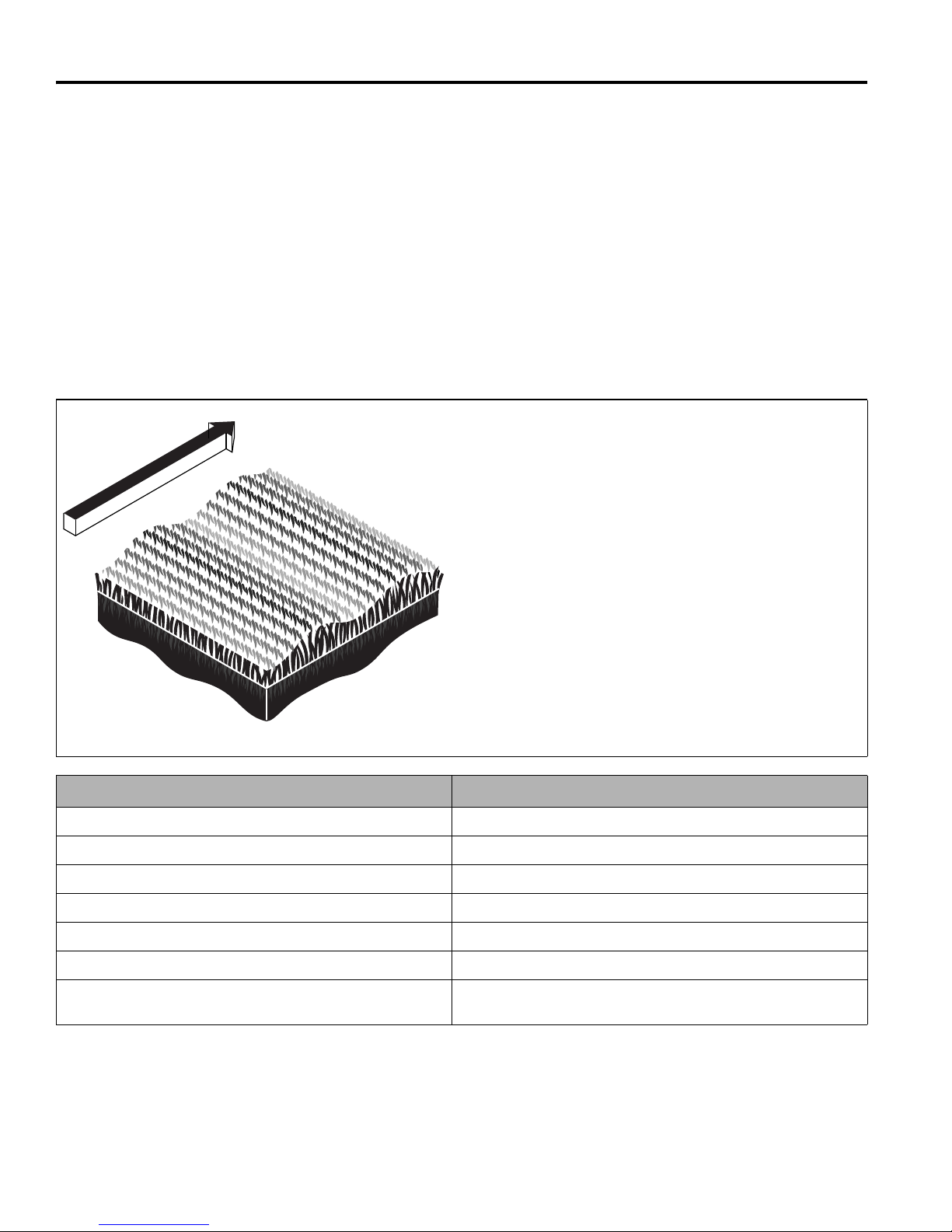
10 QUALITY OF CUT
TN0159
10 QUALITY OF CUT
10.1 QUALITY OF CUT TROUBLESHOOTING_______________________________________
It is recommended that a “test cut” be performed to
evaluate the mower’s performance before beginning
repairs.
An area should be available where “test cuts” can be
made. This area should provide known and consistent
turf conditions to allow accurate evaluation of the
mower’s performance.
Another “test cut” should be performed after the
completion of the repairs and/or adjustments to verify the
Before performing a “test cut” to diagnose cut
appearance and mower performance, the following items
should be verified to ensure an accurate “test cut.”
1. Mowing (Ground) Speed
2. Blade Sharpness
3. Height-of-Cut (HOC)
4. Roller and Roller Bearing Condition
5. Blade Speed
mower’s performance.
10.2 WASHBOARDING _________________________________________________________
Washboarding is a cyclical pattern of varying cutting
heights, resulting in a wave-like cut appearance. In most
cases, the wave tip-to-tip distance is approximately
6—8 in. (15—20 cm). Color variation (light-to-dark) may
also be noticed.
This condition is usually caused by a rocking motion in
the cutting unit(s). This condition is found mostly on
mowers with multiple (suspended) cutting units.
Washboarding may also be caused by variations in the
turf.
NOTE: Arrow indicates direction of travel.
Probable Cause Remedy
Mowing (ground) speed is too fast. Reduce mowing (ground) speed.
Grass build-up on roller. Clean the roller and scraper.
Roller is out of round. Replace roller.
Mowing in the same direction. Change mowing direction regularly.
Cutting units have too much or too little weight on them. Use traction control switch to transfer weight on or off cutting units.
Insufficient engine speed, not set to specification. Check/adjust engine speed.
Hydraulic system and/or rotary drive motor performance is
reduced.
Check hydraulic system performance (pump output, motor
operation, valve operation, relief valve settings, etc.).
50
Page 51
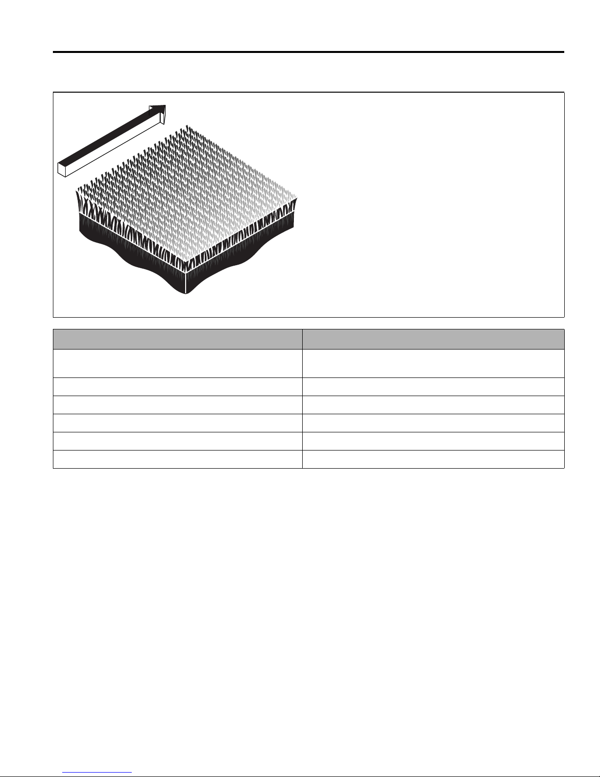
QUALITY OF CUT 10
TN0221
10.3 STEP CUTTING____________________________________________________________
Step cutting occurs when grass is cut talle r on one side of
a cutting unit than the other or on one side of mower to
the other. This is usually caused by mechanical wear or
an incorrect roller or deck caster adjustment.
NOTE: Arrow indicates direction of travel.
Probable Cause Remedy
HOC (height-of-cut) settings are different from one side of a
cutting unit to the other or from one cutting unit to another.
Worn roller bearings or deck caster wheels. Check/replace roller bearings and/or deck caster wheels.
Cutting unit movement is restricted. Check/remove cutting unit movement restriction.
Vari ations in turf density Change mowing direction.
Machine ride height is uneven side to side. Check/adjust proper tire inflation pressure.
Cutting unit height is uneven side to side. Check/adjust for even mower weight distribution.
Check HOC adjustment of cutting units.
51
Page 52
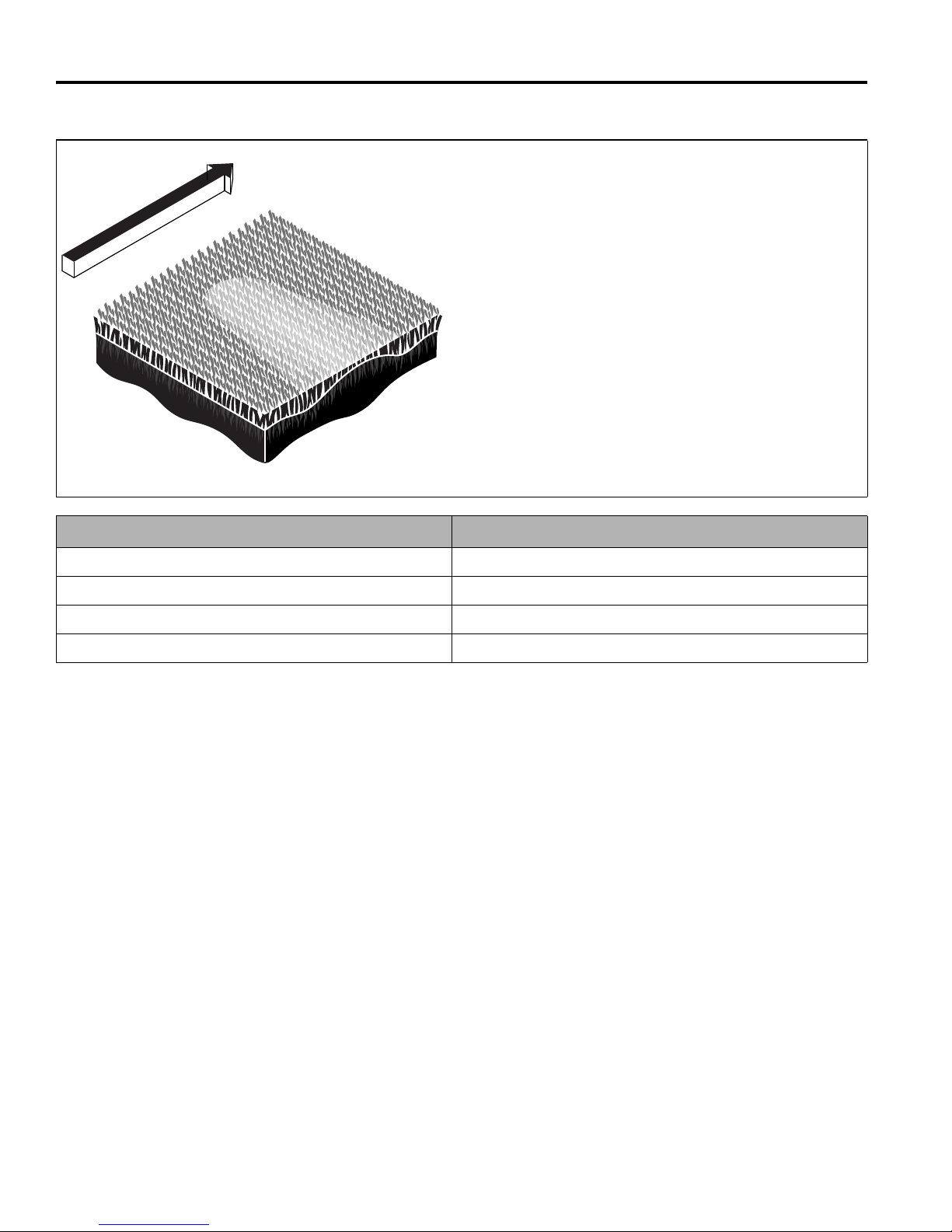
10 QUALITY OF CUT
TN0222
10.4 SCALPING _______________________________________________________________
Scalping is a condition in which areas of grass are cut
noticeably shorter than the surrounding areas, resulting in
a light green or even brown patch. This is usually caused
by an excessively low height-of-cut setting and/or uneven
turf.
NOTE: Arrow indicates direction of travel.
Probable Cause Remedy
HOC (height-of-cut) settings are lower than normal. Check and adjust the HOC settings.
Turf too uneven for the mower to follow. Change mowing direction.
Cutting too much grass at one time. Mow more often.
Mowing (ground) speed is too fast. Reduce mowing (ground) speed.
52
Page 53
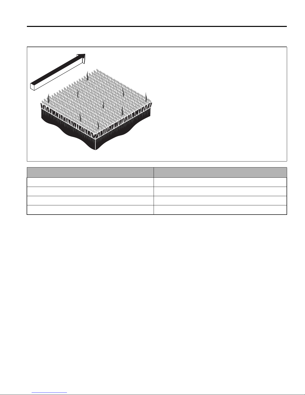
QUALITY OF CUT 10
TN0223
10.5 STRAGGLERS ____________________________________________________________
Stragglers are scattered blades of uncut or poorly cut
grass.
NOTE: Arrow indicates direction of travel.
Probable Cause Remedy
Dull cutting blade(s). Sharpen blade(s).
Mowing (ground) speed is too fast. Reduce mowing (ground) speed.
Grass is too tall. Mow more often.
Mowing in the same direction. Change mowing direction regularly.
53
Page 54
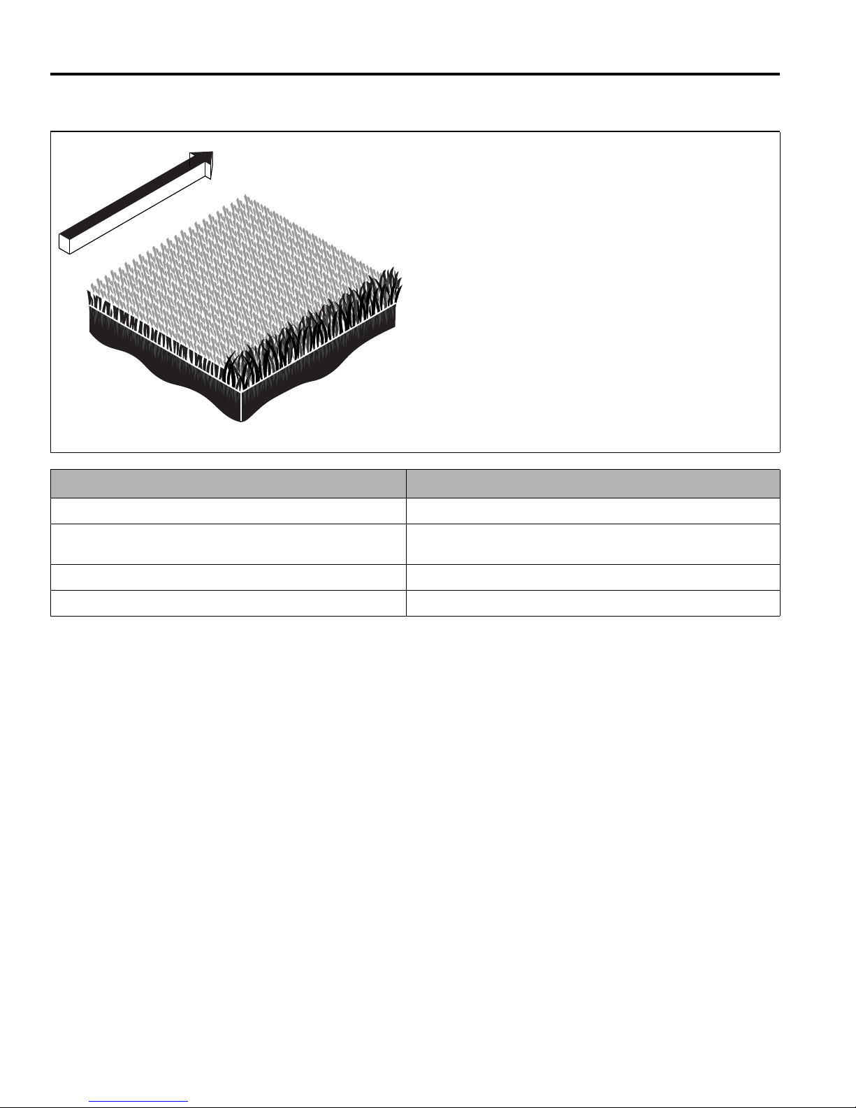
10 QUALITY OF CUT
TN0224
10.6 STREAKS ________________________________________________________________
A streak is a line of uncut grass. This is usually caused by
a damaged blade.
NOTE: Arrow indicates direction of travel.
Probable Cause Remedy
Damaged blade(s). Rep lace blade(s).
Turning too aggressively. Cutting units don’t overlap during turns
or on side hills.
Tire mats down grass before it is cut. Check/adjust tire inflation pressure.
Wet grass is matted down before it is cut. Cut when grass is dry.
Turn less aggressively to al low cutting units to overlap. Change
mowing direction or pattern on side hills .
54
Page 55
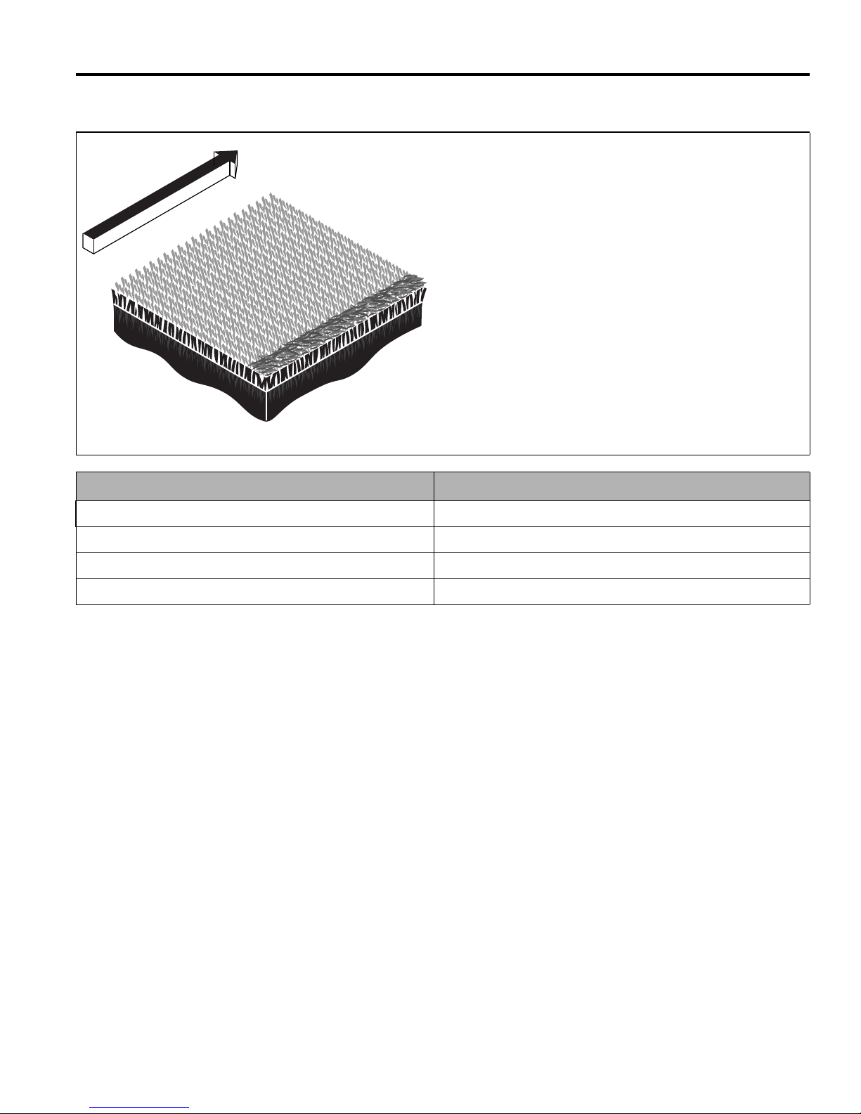
QUALITY OF CUT 10
TN0225
10.7 WINDROWING ____________________________________________________________
Windrowing is the deposit of clippings concentrated at
one end of cutting unit(s) or between cutting units,
forming line(s) in the direction of travel.
NOTE: Arrow indicates direction of travel.
Probable Cause Remedy
Grass is too tall. Mow more often.
Mowing while grass is wet. Mow when grass is dry.
Grass built up on roller. Clean rollers and scrapers.
Grass collecting on mower or cutting unit frame. Clear cutting unit(s) discharge deflector.
55
Page 56
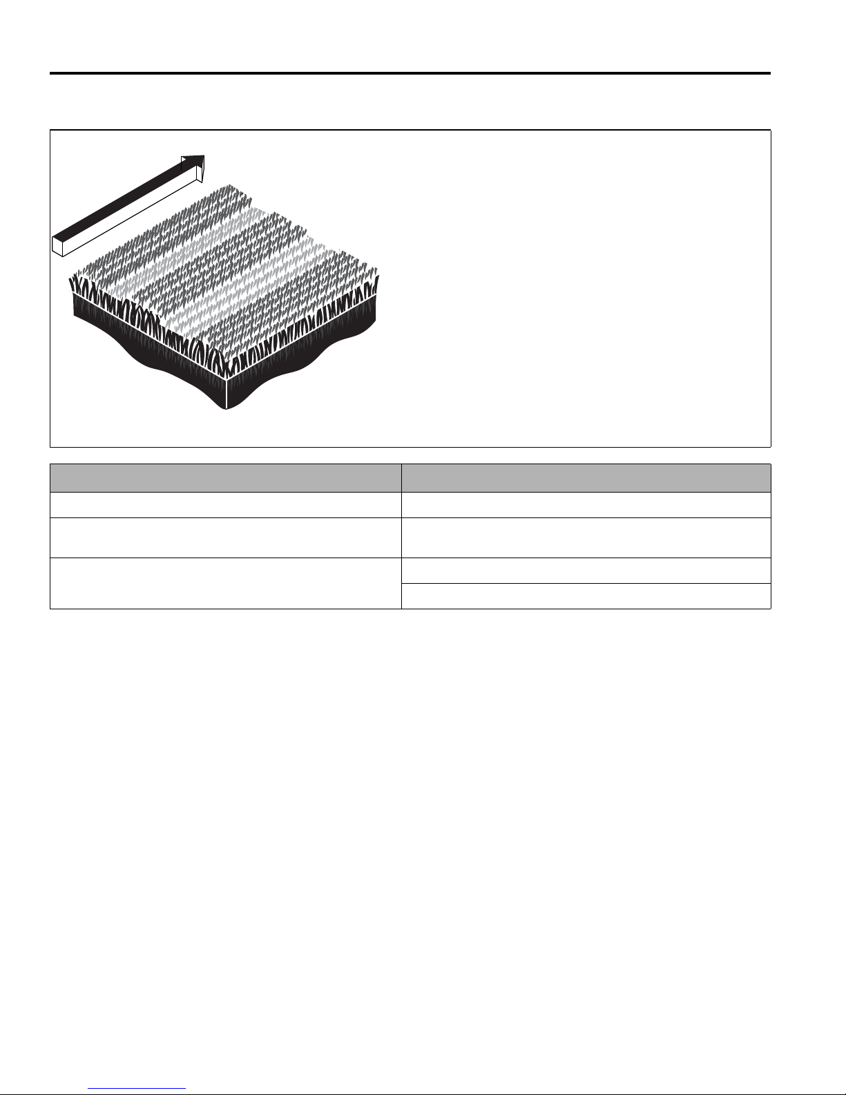
10 QUALITY OF CUT
TN1278
10.8 MISMATCHED CUTTING UNITS ______________________________________________
Mismatched cutting units is a pattern of varying cutting
heights, resulting in a stepped cut appearance, usually
due to mismatched HOC (height-of-cut) adjustment from
one cutting unit to another.
NOTE: Arrow indicates direction of travel.
Probable Cause Remedy
HOC inconsistent from one cutting unit to another. Check/adjust HOC on cutting units to same height.
Difference in rotary cutting unit speeds . Check operation of rotary cutting motor(s) and repair/replace as
necessary.
Difference in mower ride height side to side. Check/adjust tire inflation pressure.
Check/adjust for even mower weight distribution.
56
Page 57

11 NO TES
NOTES 11
57
Page 58
CHARLOTTE, NC
YEAR OF
PRODUCTION:
MADE IN U.S.A.
®
A Textron Company
PREFAZIONE
Questo manuale contiene le istruzioni di sicurezza, sui
comandi ed il funzionamento per la vostra nuova
macchina Jacobsen. Conservatelo con l’attrezzatura per
futura consultazione durante l’utilizzo.
Prima che facciate funzionare la vostra macchina, voi ed
ogni operatore che impiegate dovreste leggere con
attenzione entrambi i manuali nella loro interezza. Se
seguite le istruzioni di sicurezza, di funzionamento e di
manutenzione, prolungherete la durata della vostra
macchina ed effettuerete la relativa efficienza massima.
Per ottenere le più informazioni, mettasi in contatto con il
vostro concessionario Jacobsen.
La targa del tosaerba è situata sul sul longherone
posteriore sinistro. Jacobsen consiglia di prendere nota
dei numeri qui di seguito, a titolo di riferimento.
Questa è una traduzione delle istruzioni originali
verificata da ACMTRAD SL.
© 2013, Jacobsen, A Textron Company/Textron Innovations Inc.
“Tutti i diritti riservati, compreso quello di riproduzione totale o
parziale in qualunque forma.”
STAMPATO NEGLI U.S.A. 9-2014
it-2
Avviso: Proposta 65
Questo prodotto contiene o emette
sostanze chimiche riconosciute dallo
Stato della California come causa di
cancro e difetti congeniti od altri danni
riproduttivi.
Page 59

INDICE
INDICE
1 SICUREZZA
1.1 Sicurezza del funzionamento...................... 4
1.2 Note importanti di sicurezza ....................... 5
2 CARATTERISTICHE TECHNICHE
2.1 Identificazione del prodotto ........................ 6
2.2 Motore V2403-M-DI .................................... 6
2.3 Tosaerba .................................................... 6
2.4 Pesi e dimensioni ....................................... 6
2.5 Gruppo di falciatura .................................... 7
2.6 Accessori .................................................... 7
2.7 Documentazione a supporto ...................... 7
2.8 Dichiarazione di conformità ........................ 8
2.9 Livelli vibrazionali ....................................... 11
3 DECALCOLMANIE
4 COMANDI
4.1 Icone .......................................................... 16
4.2 Comandi...................................................... 17
4.3 Plancia comandi ......................................... 19
4.4 Spie di segnalazione per l'operatore .......... 20
5 FUNZIONAMENTO
5.1 Ispezione giornaliera .................................. 21
5.2 Sistema di interblocco ................................ 21
5.3 Procedimenti di funzionamento .................. 22
5.4 Avviamento ................................................ 23
5.5 Arresto / parcheggio ................................... 23
5.6 Guida / trasporto ........................................ 24
5.7 Falciatura ................................................... 24
5.8 Velocità di falciatura ................................... 24
5.9 Guida in pendenza ..................................... 25
5.10 Rimorchio / trazione ................................... 27
5.11 Manutenzione giornaliera ........................... 28
6 TABELLE DELLA MANUTENZIONE
E LUBRIFICAZIONE
6.1 Dati generali ............................................... 29
6.2 Tabella della manutenzione ....................... 29
6.3 Tabella della lubrificazione ......................... 30
7.12 Olio idraulico .............................................. 34
7.13 Filtri dell’impianto idraulico ......................... 35
7.14 Sistema elettrico ......................................... 35
7.15 Radiatore .................................................... 36
7.16 Gabbia antiribaltamento (ROPS) ............... 36
7.17 Pneumatici ................................................. 36
7.18 Procedimento di montaggio delle ruote ...... 37
7.19 Ispezione delle lame .................................. 37
7.20 Affilatura delle lame .................................... 38
7.21 Cura e pulizia ............................................. 38
7.22 Conservazione ........................................... 39
8 REGOLAZIONI
8.1 Dati generali ............................................... 40
8.2 Velocità di falciatura ................................... 40
8.3 Cinghia ....................................................... 40
8.4 Regolazione del folle .................................. 41
8.5 Marce avanti / retromarcia ......................... 41
8.6 Rilevamento della sterzata ......................... 42
8.7 Taratura del sistema di comando
della trazione .............................................. 42
8.8 Altezza di taglio .......................................... 43
8.9 Specifica della coppia ................................ 44
9 SOLUZIONE DEI PROBLEMI
9.1 Dati generali ............................................... 45
9.2 Spie della centralina ................................... 46
9.3 Circuiti elettrici ............................................ 47
10 QUALITÀ DI TAGLIO
10.1 Interventi correttivi sulla qualità di taglio .... 48
10.2 Ondulazione ............................................... 48
10.3 Taglio a gradini ........................................... 49
10.4 Escalpado ................................................... 50
10.5 Fili d’erba alti .............................................. 51
10.6 Strisce non falciate ..................................... 52
10.7 Andanatura ................................................. 53
10.8 Apparati di taglio spaiati ............................. 54
11 NOTE
7 MANUTENZIONE
7.1 Dati generali ............................................... 31
7.2 Motore ........................................................ 31
7.3 Olio del motore ........................................... 31
7.4 Filtro dell’aria .............................................. 32
7.5 Carburante ................................................. 32
7.6 Sistema del carburante .............................. 32
7.7 Batteria ....................................................... 33
7.8 Messa in moto con il collegamento di
due batterie ................................................ 33
7.9 Caricamento della batteria ......................... 33
7.10 Silenziatore e tubo di scarico ..................... 34
7.11 Tubi idraulici flessibili ................................. 34
it-3
Page 60

1 SICUREZZA
!
1 SICUREZZA
1.1 UTILIZZO IN PIENA SICUREZZA_______________________________________________
AVVERTENZA
LE APPARECCHIATURE AZIONATE IN MODO IMPROPRIO O DA PERSONALE NON ADDESTRATO
Prendere confidenza con l'ubicazione e il corretto funzionamento dei comandi. Prima di utilizzare il tosaerba, gli
operatori inesperti devono essere istruiti da una persona che conosce il corretto funzionamento delle
apparecchiature.
Usare soltanto ricambi, accessori e attrezzi approvati da Jacobsen.
POSSONO ESSERE PERICOLOSE.
USO SICURO
a Leggere il Manuale d'uso e tutto il materiale
formativo. Se l’operatore o il tecnico non è in grado
di leggere questo manuale, il proprietario ha la
responsabilità di spiegargli il contenuto nel
presente manuale. Manuali in altre lingue possono
essere disponibili nei siti Web di Jacobsen o
Ransomes Jacobsen.
a Leggere attentamente tutte le istruzioni di questo
tosaerba. Apprendere il funzionamento dei
comandi e l'uso corretto delle attrezzature.
b L’uso di questo tosaerba non deve essere mai
consentito a bambini e a persone che non sono in
grado di comprendere le presenti istruzioni. Le
normative locali possono imporre limiti all’età
dell’operatore.
c Mai utilizzare il tosaerba in prossimità di persone
(bambini inclusi) o animali.
d Tenere presente che l’operatore o il proprietario è
responsabile di eventuali incidenti o pericoli a cui
possono essere esposte le altre persone o i loro
beni.
e Non trasportare passeggeri.
f Non consentire mai a nessuno di utilizzare o
svolgere la manutenzione del tosaerba o dei
relativi accessori senza seguire le corrette
istruzioni.
g Non utilizzare le apparecchiature sotto gli effetti di
stanchezza, malattie, alcol o droghe.
PREPARAZIONE
a Quando si utilizza il tosaerba, indossare un
abbigliamento adeguato, scarpe o stivaletti
antiscivolo da lavoro, guanti da lavoro, elmetto,
occhiali protettivi e protezioni acustiche. Capelli
lunghi, indumenti larghi e monili potrebbero
rimanere impigliati nelle parti in movimento.
b Non utilizzare mai la macchina se il blocco di
sicurezza è disattivato o guasto. Non scollegare o
impedire il funzionamento degli interruttori.
c Mai utilizzare la macchina se non è in condizioni
operative perfette o se manca di adesivi,
protezioni, schermi, deflettori o altri dispositivi
protettivi ben fissati.
d Ispezionare il tosaerba prima dell'uso. Verificare la
pressione degli pneumatici, il livello dell'olio
motore, il livello del liquido refrigerante e
l'indicatore del filtro dell'aria. Il carburante è
infiammabile. Fare attenzione quando si rifornisce
il tosaerba di carburante.
e Utilizzare il tosaerba durante le ore diurne o in
buone condizioni di illuminazione artificiale. Usare
con cautela il tosaerba in caso di condizioni
meteorologiche avverse. Mai utilizzare il tosaerba
se esiste il pericolo di fulmini in zona.
f Ispezionare l'area per scegliere gli accessori e le
attrezzature necessarie per svolgere il lavoro in
modo corretto e sicuro. Usare soltanto ricambi,
accessori e attrezzi approvati da Jacobsen.
g Fare attenzione a eventuali buche nel terreno e
altri potenziali pericoli non visibili.
h Ispezionare l'area in cui viene utilizzata la
macchina. Rimuovere tutti gli ostacoli possibili
prima dell'uso. Prestare attenzione sia agli ostacoli
sopraelevati (rami, fili elettrici, ecc.) che a quelli
sotterranei (irrigatori, tubazioni, radici, ecc.). Usare
la massima cautela quando si accede a una nuova
area. Individuare potenziali pericoli.
i Ispezionare il sistema di taglio prima di avviare il
tosaerba. Assicurarsi che le lame possano ruotare
liberamente. Quando si fa ruotare una lama, anche
le altre lame possono mettersi in rotazione.
FUNZIONAMENTO
a Mai avviare il motore in ambienti non
adeguatamente ventilati o in ambienti chiusi. Il
monossido di carbonio presente nei gas di scarico
può accumularsi fino a raggiungere livelli pericolosi
per la salute.
b Non trasportare passeggeri. Tenere altre persone e
animali a debita distanza dal tosaerba.
c Disinnestare le trasmissioni e azionare il freno di
stazionamento prima di avviare il motore. Avviare il
motore solo quando l'operatore è seduto al suo
posto. Mai avviare il motore se ci sono persone in
prossimità del tosaerba.
d Tenere gambe, braccia e corpo all’interno
dell’abitacolo mentre il veicolo è in funzione.
Tenere mani e piedi lontani dagli apparati di taglio.
e Non utilizzare su pendenze superiori a quelle
massime consentite.
it-4
Page 61

SICUREZZA 1
f Per evitare ribaltamenti o perdite di controllo:
– Guidare il tosaerba in salita e discesa (in verticale),
non trasversalmente (in orizzontale) rispetto alla
pendenza.
– Non arrestare o avviare improvvisamente la
macchina su superfici in pendenza.
– Moderare la velocità quando si guida in pendenza
o quando si deve curvare. Usare cautela nei cambi
di direzione. Le condizioni del manto erboso
possono modificare la stabilità del tosaerba.
– Usare cautela quando si usa il tosaerba in
prossimità di scarpate, fossati o argini.
– Fare attenzione a eventuali buche nel terreno e
altri potenziali pericoli non visibili.
g Quando si guida in retromarcia, guardare dietro il
veicolo e in basso per assicurarsi di avere via
libera. Non azionare gli apparati di taglio quando si
guida in retromarcia.
h Usare cautela in prossimità di angoli, alberi o altri
oggetti che possono limitare la visibilità.
i La macchina deve soddisfare i requisiti del Codice
della strada per essere guidata su strade
pubbliche.
j Prima di attraversare strade o sentieri, disinserire
l'interruttore della presa di forza, sollevare gli
apparati di taglio e procedere a bassa velocità.
Fare attenzione al traffico.
k Fermare le lame quando il tosaerba si trova su
superfici non erbose.
l Non scagliare l'erba tagliata in direzione di altre
persone o non consentire ad altre persone di
sostare in prossimità del tosaerba quando è in
funzione.
m Mai utilizzare la macchina con protezioni
danneggiate o dispositivi di sicurezza mancanti.
n Non modificare l'impostazione del regolatore del
motore e non aumentare il regime del motore. Mai
modificare o manomettere i dispositivi di
regolazione protetti da sigilli per il controllo del
regime di rotazione del motore.
o Prima di allontanarsi dalla postazione
dell’operatore per qualsiasi motivo:
– Disinnestare tutte le trasmissioni e abbassare le
attrezzature al livello del terreno.
– Azionare il freno di stazionamento.
– Spegnere il motore e rimuovere la chiave.
p Quando si urta un oggetto o il tosaerba inizia a
vibrare in modo anomalo, ispezionare il tosaerba e
apportare le necessarie riparazioni.
q Prima di spegnere il motore, ridurre l'apertura
dell'acceleratore.
r Non utilizzare le attrezzature per scopi diversi da
quelli previsti per il tosaerba.
ROPS
a Il ROPS è un dispositivo di sicurezza. Mantenere il
ROPS bloccato in posizione verticale. Allacciare
sempre la cintura di sicurezza quando si utilizza il
tosaerba. Accertarsi che la cintura di sicurezza
possa essere slacciata rapidamente in caso di
emergenza.
b Usare il tosaerba con il ROPS richiuso solo su
superfici piane e regolari, se necessario. Mai usare
il tosaerba con il ROPS richiuso su pendenze o in
prossimità di scarpate o specchi d'acqua. Il ROPS
richiuso non offre alcuna protezione in caso di
ribaltamento.
c Verificare l'altezza del veicolo prima di passare
sotto altri oggetti. Non urtare rami, cavi elettrici o
altri oggetti con il ROPS.
d Non utilizzare la cintura di sicurezza quando il
ROPS è richiuso.
e Ispezionare il ROPS in cerca di danni. Assicurarsi
che tutti gli elementi di fissaggio del ROPS siano
serrati.
f Non saldare, forare, modificare o piegare il ROPS.
Sostituire il ROPS se danneggiato. Non tentare di
riparare un ROPS danneggiato.
g Non rimuovere il ROPS dal tosaerba.
h Jacobsen deve approvare qualsiasi modifica al
ROPS.
GESTIONE SICURA DEI COMBUSTIBILI
a Il carburante e i suoi vapori sono infiammabili. Fare
attenzione quando si rifornisce il tosaerba di
carburante. I vapori di carburante possono
provocare esplosioni.
b Mai utilizzare contenitori non omologati per il
trasporto o la conservazione di carburante.
c Mai lasciare il tosaerba o le taniche di carburante
in prossimità di fiamme libere o altri oggetti che
potrebbero incendiare il carburante o i suoi vapori.
d Mai riempire le taniche di carburante all'interno di
veicoli o rimorchi con rivestimenti in plastica.
Posare sempre le taniche di carburante a terra e
lontane dal veicolo prima di riempirle.
e Rifornire di carburante il tosaerba prima di avviare
il motore. Mai rimuovere il tappo del serbatoio o
rifornire il tosaerba quando il motore è in funzione
o è caldo.
f Effettuare i rifornimenti di carburante soltanto
all'aperto e non fumare durante l'operazione.
Estinguere qualsiasi fonte di innesco.
g L'erogatore del carburante deve toccare il
bocchettone del serbatoio quando si rifornisce il
tosaerba. Non utilizzare dispositivi che bloccano
l'erogatore del carburante in posizione aperta.
it-5
Page 62

1 SICUREZZA
h Non riempire eccessivamente il serbatoio del
carburante. Lasciare almeno 2,5 cm sotto il
bocchettone di rifornimento.
i Chiudere sempre il tappo del serbatoio e della
tanica dopo il rifornimento.
j Se il carburante schizza sui vestiti, cambiarli
immediatamente.
MANUTENZIONE E RIMESSAGGIO
a Prima di pulire, regolare o riparare questo
apparecchio, portare l'interruttore della presa di
forza nella posizione OFF, abbassare l'apparato di
taglio al terreno, inserire il freno di stazionamento,
spegnere il motore e rimuovere la chiave.
b Il tosaerba deve essere parcheggiato su terreno
sodo e pianeggiante.
c Mai lavorare su un tosaerba sollevato, sostenuto
solo da un cavalletto. Utilizzare sempre i cavalletti.
d Non consentire mai a nessuno di utilizzare o
svolgere la manutenzione del tosaerba o dei
relativi accessori senza seguire le corrette
istruzioni.
e Quando il tosaerba deve essere parcheggiato,
messo in deposito o lasciato incustodito,
abbassare i dispositivi di taglio, eccetto nei casi in
cui vengano adoperati sistemi di blocco adeguati.
f Quando si carica il tosaerba su un rimorchio o lo si
mette in deposito, chiudere la valvola del
carburante. Non tenere il carburante vicino a
fiamme e non drenarlo in ambienti chiusi.
g Scollegare la batteria prima di svolgere la
manutenzione del tosaerba. Scollegare sempre il
cavo negativo della batteria prima del cavo
positivo. Collegare sempre il cavo positivo della
batteria prima del cavo negativo.
h Caricare la batteria in un'area con una buona
circolazione d'aria. La batteria può rilasciare
idrogeno gassoso potenzialmente esplosivo. Per
evitare esplosioni, tenere qualsiasi fonte potenziale
di scintille o fiamme a debita distanza dalla
batteria.
i Scollegare il caricabatteria dall'alimentazione
prima di collegare o scollegare il caricabatteria
dalla batteria. Indossare indumenti protettivi e
utilizzare attrezzi isolati quando si lavora sulla
batteria.
j Fare attenzione e indossare guanti protettivi
quando si ispezionano o si sostituiscono le lame
degli apparati di taglio. Sostituire le lame
danneggiate, senza tentare di ripararle.
l Usare cautela quando si rilascia la pressione di
componenti dotati di energia residua.
m Per evitare infortuni causati da olio caldo e ad alta
pressione, mai utilizzare le mani per individuare
eventuali perdite d'olio. Utilizzare carta o cartone
per individuare le perdite.
n La pressione del liquido idraulico può essere
sufficiente a penetrare nella pelle. Se il liquido
idraulico riesce a penetrare nella pelle, è
necessario rimuovere chirurgicamente tutto il
liquido entro poche ore per impedire il
sopraggiungere della cancrena.
o Quando si sottopone a manutenzione l'impianto
idraulico, assicurarsi che raccordi, tubi e flessibili
siano serrati alla coppia necessaria. Assicurarsi
che l'impianto idraulico sia in buone condizioni
prima di avviare il motore.
p Mantenere puliti il tosaerba e il motore.
q Lasciare raffreddare il motore prima del
rimessaggio e rimuovere sempre la chiave di
accensione.
r Mantenere ben serrati dadi, bulloni e viti per
garantire che le attrezzature operino sempre in
piena sicurezza.
s Sostituire le parti logore o danneggiate per
salvaguardare la sicurezza. Sostituire gli adesivi
danneggiati o usurati. Usare soltanto ricambi,
accessori e attrezzi approvati da Jacobsen.
t Per ridurre il rischio di incendio, rimuovere i
materiali infiammabili in prossimità di motore,
silenziatore, vano batteria e serbatoio del
carburante.
u Scollegare la batteria e i connettori della centralina
prima di eseguire saldature sul tosaerba.
QUANDO SI CARICA IL TOSAERBA SU UN
RIMORCHIO
a Fare attenzione quando si carica o scarica il
tosaerba da un rimorchio. Il rimorchio deve essere
più largo del tosaerba e deve essere in grado di
reggere il peso del tosaerba.
b Utilizzare una rampa a tutta larghezza per caricare
o scaricare il tosaerba da un rimorchio.
c Utilizzare cinghie, catene, cavi o funi per fissare il
tosaerba al rimorchio. Devono essere fissate
cinghie davanti e dietro, lungo i lati del rimorchio.
d Assicurarsi che tutti i sistemi di fissaggio siano
serrati correttamente.
k Tenere mani e piedi lontani dalle parti in
movimento. Non regolare il tosaerba con il motore
in funzione, a meno che la regolazione non lo
richieda espressamente.
it-6
Page 63

SICUREZZA 1
!
!
1.2 NOTE IMPORTANTI DI SICUREZZA ___________________________________________
Questo simbolo di allarme di sicurezza viene utilizzato per indicare pericoli potenziali.
PERICOLO - Indica una situazione imminentemente pericolosa che, se non evitata, PROVOCHERÀ la morte o gravi
lesioni.
AVVERTENZA - Indica una situazione potenzialmente pericolosa che, se non evitata, POTREBBE provocare la
morte o gravi lesioni.
ATTENZIONE - Indica una situazione potenzialmente pericolosa che, se non evitata, PROBABILMENTE
provocherà lesioni a persone e danni, di entità da minore a moderata, a proprietà. Può essere utilizzato anche per
segnalare azioni pericolose.
AVVISO - Indica una condizione potenzialmente pericolosa che, se non viene evitata, PUÒ causare danni. Può
essere utilizzato anche per segnalare azioni pericolose.
Per chiarezza alcune illustrazioni in questo manuale possono riprodurre schermi, ripari o piastre aperti o rimossi.
Questa apparecchiatura non deve mai essere utilizzata se questi dispositivi non sono correttamente fissati in
posizione.
AVVERTENZA
Il sistema microinterruttori di sicurezza impedisce l’avviamento del tosaerba a meno che
la leva del freno sia inserita, l’interruttore della presa di forza (PDF) sia in posizione OFF
(disinserito) ed il pedale di trazione sia in folle. Il sistema ferma inoltre il motore se
l’operatore lascia il sedile senza inserire il freno di stazionamento o disinserire
l’interruttore della presa di forza.
NON azionare mai il tosaerba se il sistema microinterruttori di sicurezza non funziona.
AVVERTENZA
1. Prima di lasciare il sedile per qualsiasi motivo l’operatore deve:
a. Riportare il pedale di trazione alla posizione in FOLLE.
b. Disinnestare tutti i comandi.
c. Abbassare tutti gli attrezzi a terra.
d. Innestare il freno di stazionamento.
e. Fermare il motore e rimuovere la chiave di accensione.
2. Tenere le mani, i piedi e gli indumenti lontano dalle parti moventi. Attendere che tutti i
movimenti siano fermi prima di pulire, regolare o effettuare la manutenzione sulla macchina.
3. Tenere l’area libera da tutti gli astanti e gli animali domestici.
4. Non trasportare mai passeggeri, a meno che un sedile apposito sia compreso.
5. Non azionare mai il dispositivo di taglio se il deflettore dello scarico non è correttamente
montato in posizione.
Seguendo tutte le istruzioni fornite in questo manuale, sarà prolungata la durata della macchina e questa manterrà
intatta la propria efficienza. Le regolazioni e la manutenzione devono essere effettuate in tutti i casi da un tecnico
qualificato.
Rivolgersi al proprio concessionario Jacobsen che dispone di dati sui metodi di manutenzione più recenti per
mantenere questo apparecchio ed è in grado di fornire l’assistenza pronta ed efficiente ai clienti.
it-7
Page 64
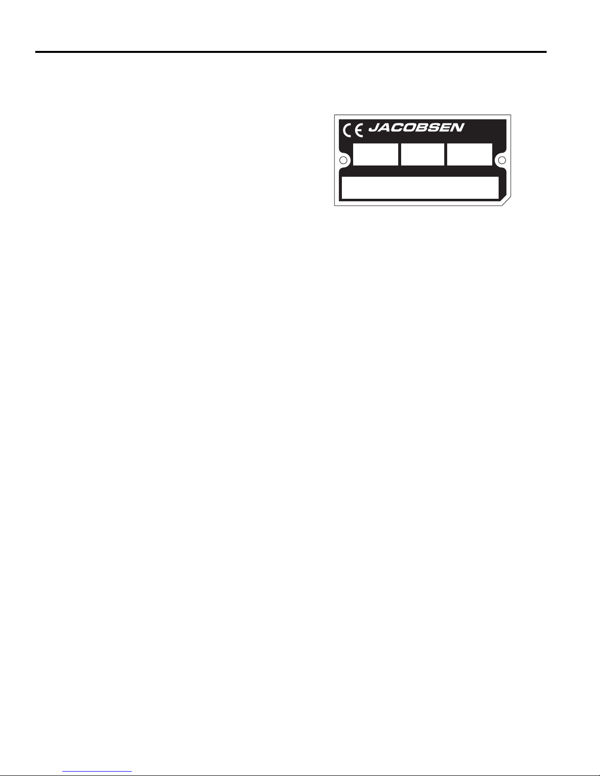
2 CARATTERISTICHE TECHNICHE
1674 36.5 XXXX
6813101651
2 Caratteristiche techniche
2.1 IDENTIFICAZIONE DEL PRODOTTO __________________________________________
68131.............................. AR522-T4I, 5 apparati, 4 ruote
motrice (4WD) con ROPS
Numero di serie .............. Il numero di serie è riportato sulla
targhetta di identificazione, come
quella illustrata, affissa al telaio
del tosaerba, sopra l’assale
posteriore, a destra dell'operatore.
In sede di ordinazione di parti di ricambio o per richieste d’
PRODUCT OF U.S .A.
ABC
kg kW
A Textron Company
D
assistenza si prega di citare sempre il numero di serie
dell’unità.
2.2 MOTORE V2403-M-DI ______________________________________________________
®
11524 WILMA R BL VD,
CHA R L OT TE , NC 28273
1-800-848-1636 (US)
Marca.............................. Kubota
Modello ........................... V2403-M-DI Diesel, 4 tempi,
raffreddamento a liquido
Potenza........................... 36,5 kW a 2700 giri/min
Nota: La potenza continua effettivamente erogata sarà
probabilmente inferiore a quella riportata nelle caratter
istiche tecniche a causa delle limitazioni operative e dei
fattori ambientali.
Alesaggio...................... 87 mm
Corsa............................ 102,4 mm
Cilindrata......................... 2434 cm
3
Coppia ............................ 158 Nm a 1600 giri/min
Numero di cetano ..... Min. 45
Capacità ................... 65 litri
Regolatore:
Minima superiore...... 2920 giri/min
Minima inferiore........ 1000 giri/min
Lubrificazione:
Capacità ................... 9,5 litri
Tipo........................... SAE 10W30
Classifica API ........... CJ-4
Filtro dell’aria .................. Donaldson, a secco con valvola di
sfiato e indicazione di servizio.
Alternatore...................... 45 A
Carburante:
Tipo........................... Gasolio 2D a basso o bassissimo
contenuto di zolfo
2.3 TOSAERBA ______________________________________________________________
Pneumatici:
Anteriori ................... 26,5 x 14 - 12: (6 tele)
Posteriori .................. 22,5 x 10 - 8
Pressione pneumatici:
Anteriori .................... 111 kPa
Posteriori................... 83 kPa
Batteria:
Tipo........................... 12 V, 600 ampère a freddo
Gruppo...................... BCI 24
Freni:
Di servizio ................Frenatura dinamica mediante il
circuito di trazione.
Di stazionamento ......Integrato nel motore delle ruote,
Velocità:
Tosatura ................... 0 - 11 km/h
Trasferimento ........... 0 –19,3 km/h
Retromarcia ............. 0 – 8,1 km/h
Produzione ..................... 6,4 acri/h a 11 km/h
Impianto idraulico:
Capacità ......................... 37,85 litri
Tipo di fluido ................... GreensCare 68
Raffreddamento.............. Radiatore dell’olio
Filtro del tubo di ritorno... 10 micron
Sterzo ............................. Servosterzo idrostatico
rilascio idraulico
2.4 PESI E DIMENSIONI _______________________________________________________
Dimensioni: mm
Lunghezza................................................................ 3302
Altezza – Cima della ROPS...................................... 2108
Larghezza - Tosatura................................................ 2486
Larghezza - Trasferimento........................................ 2489
it-8
Peso: kg
Serbatoio pieni, piatti di taglio sollevati, senza operatore.
Totale........................................................................ 1674
Serbatoio vuoto, piatti di taglio sollevati, senza operatore.
Totale ....................................................................... 1619
Page 65

CARATTERISTICHE TECHNICHE 2
!
2.5 GRUPPO DI FALCIATURA ___________________________________________________
Larghezza di taglio totale ................ 2,54 m
Numero di apparati di taglio ............ Cinque: tre anteriori,
due posteriori.
Altezza di taglio............................... Da 19 a 133 mm con
incrementi di 6 mm
2.6 ACCESSORI ______________________________________________________________
Per la lista completa di accessori e attrezzature si rimanda
al Catalogo dei ricambi, o al concessionario Jacobsen di
zona.
ATTENZIONE
L’uso di ricambi e accessori non autorizzati da Jacobsen può causare infortuni o danneggiare l’attrezzatura, ed
annullare la garanzia.
Dispositivo antiribaltamento ROPS di ricambio
a 2 montanti con cintura di sicurezza..... 67844
Tettuccio / Parasole......... ...................... 68127
Fermo di bloccaggio cofano................... 1004049
Abitacolo completo................................. 4265201/ 4265202
2.7 DOCUMENTAZIONE A SUPPORTO ___________________________________________
Per ottenere l’elenco completo di accessori e raccordi,
rivolgersi al proprio rivenditore Jacobsen.
Manuale di sicurezza, uso e manutenzione...... 4273092
Manuale dei ricambi........ ................................. 4273091
Catalogo dei ricambi del motore ....................... 4273093
Manuale di revisione e riparazione ...................(Da
determinare)
Lama standard................ ................................. 4163106
Lama ad alto carico ........ ................................. 4137186
Lama a basso carico....... ................................. 4124087
it-9
Page 66

2 CARATTERISTICHE TECHNICHE
GB
United
Kingdom
BE
BelgiumBGBulgariaCHSwitzerlandCNChinaCYCyprusCZCzech
Republic
DE
GermanyDKDenmarkEEEstoniaESSpainFIFinlandFRFranceGRGreeceHUHungaryISIcelandITItaly
JP
JapanKRKoreaLILiechensteinLTLithuaniaLVLatviaMTMaltaNLNetherlandsNONorwayPLPolandPTPortugalRORomaniaRURussiaSESwedenSISloveniaSKSlovakiaTRTurkeyUAUkrain
2.8 DICHIARAZIONE DI CONFORMITÀ ___________________________________________
DECLARATION OF CONFORMITY ▪ ДЕКЛАРАЦИЯ ЗА СЪОТВЕТСТВИЕ ▪ PROHLÁŠENÍ O SHODĚ ▪
OVERENSSTEMMELSESERKLÆRING ▪ CONFORMITEITSVERKLARING ▪ VASTAVUSDEKLARATSIOON ▪
VAATIMUSTENMUKAISUUSVAKUUTUS ▪ DECLARATION DE CONFORMITE ▪ KONFORMITÄTSERKLÄRUNG ▪
ΔΗΛΩΣΗ ΣΥΜΜΟΡΦΩΣΗΣ ▪ MEGFELELŐSÉGI NYILATKOZAT ▪ DICHIARAZIONE DI CONFORMITÀ ▪ ATBILSTĪBAS
DEKLARĀCIJA ▪ ATITIKTIES DEKLARACIJA ▪ DIKJARAZZJONI TAL-KONFORMITÀ ▪ DEKLARACJA ZGODNOŚCI ▪
DECLARAÇÃO DE CONFORMIDADE ▪ DECLARAŢIE DE CONFORMITATE ▪ VYHLÁSENIE O ZHODE ▪ IZJAVA O
SKLADNOSTI ▪ DECLARACIÓN DE CONFORMIDAD ▪ DEKLARATION OM ÖVERENSSTÄMMELSE ▪
SAMRÆMISYFIRLÝSING ▪ KONFORMITETSERKLÆRING ▪ 符合性声明 ▪ SAMRÆMISYFIRLÝSING ▪ 適合宣言 ▪
적합성 선언서 ▪ UYGUNLUK BEYANI ▪ ДЕКЛАРАЦІЯ ПРО ВІДПОВІДНІСТЬ
Business name and full address of the manufacturer ▪ Търговско име и пълен адрес на производителя ▪ Obchodní jméno a plná adresa výrobce ▪
Producentens firmanavn og fulde adresse ▪ Bedrijfsnaam en volledig adres van de fabrikant ▪ Tootja ärinimi ja täielik aadress ▪
Valmistajan toiminimi ja täydellinen osoite ▪ Nom commercial et adresse complète du fabricant ▪ Firmenname und vollständige Adresse des Herstellers ▪
Επωνυμία και ταχυδρομική διεύθυνση κατασκευαστή ▪ A gyártó üzleti neve és teljes címe ▪ Ragione sociale e indirizzo completo del fabbricante ▪
Uzņēmuma nosaukums un pilna ražotāja adrese ▪ Verslo pavadinimas ir pilnas gamintojo adresas ▪ Isem kummerċjali u indirizz sħiħ tal-fabbrikant ▪
Nazwa firmy i pełny adres producenta ▪ Nome da empresa e endereço completo do fabricante ▪
Denumirea comercială şi adresa completă a producătorului ▪ Obchodný názov a úplná adresa výrobcu ▪ Naziv podjetja in polni naslov proizvajalca ▪
Nombre de la empresa y dirección completa del fabricante ▪ Tillverkarens företagsnamn och kompletta adress ▪
Fyrirtækisheiti og fullt heimilisfang framleiðanda ▪ Firmanavn og full adresse for produsenten ▪ 制造商的商业名称和完整地址 ▪
Nafn fyrirtækis og fullt heimilisfang framleiðanda ▪ 商号およびメーカーの正式住所 ▪ 제조자의 상호명 및 주소 ▪ İmalatçının ticari ünvanı ve açık adresi ▪
Фірмове найменування і повна адреса виробника
Product Code ▪ Код на продукта ▪ Kód výrobku ▪ Produktkode ▪ Productcode ▪ Toote kood ▪ Tuotekoodi ▪ Code produit ▪ Produktcode ▪
Κωδικός προϊόντος ▪ Termékkód ▪ Codice prodotto ▪ Produkta kods ▪ Produkto kodas ▪ Kodiċi tal-Prodott ▪ Kod produktu ▪ Código do Produto ▪
Cod produs ▪ Kód výrobku ▪ Oznaka proizvoda ▪ Código de producto ▪ Produktkod ▪ Vörunúmer ▪ Produktkode ▪ 产品代码 ▪ Framleiðslunúmer ▪
製品コード ▪ 제품 코드 ▪ Ürün Kodu ▪ Код виробу
Machine Name ▪ Наименование на машината ▪ Název stroje ▪ Maskinnavn ▪ Machinenaam ▪ Masina nimi ▪ Laitteen nimi ▪ Nom de la machine ▪
Maschinenbezeichnung ▪ Ονομασία μηχανήματος ▪ Gépnév ▪ Denominazione della macchina ▪ Iekārtas nosaukums ▪ Mašinos pavadinimas ▪
Isem tal-Magna ▪ Nazwa urządzenia ▪ Nome da Máquina ▪ Numele echipamentului ▪ Názov stroja ▪ Naziv stroja ▪ Nombre de la máquina ▪
Maskinens namn ▪ Heiti tækis ▪ Maskinnavn ▪ 机器名称 ▪ Nafn vélar ▪ 機械名 ▪ 기기 명칭 ▪ Makine Adı ▪ Назва машини
Designation ▪ Предназначение ▪ Označení ▪ Betegnelse ▪ Benaming ▪ Nimetus ▪ Tyyppimerkintä ▪ Pažymėjimas ▪ Bezeichnung ▪ Χαρακτηρισμός ▪
Megnevezés ▪ Funzione ▪ Apzīmējums ▪ Lithuanian ▪ Denominazzjoni ▪ Oznaczenie ▪ Designação ▪ Specificaţie ▪ Označenie ▪ Namen stroja ▪
Descripción ▪ Beteckning ▪ Merking ▪ Konstruksjon ▪名称 ▪ Útnefning ▪ 用途 ▪ 지정 ▪ Tanımı ▪ Позначення
Serial Number ▪ Сериен номер ▪ Sériové číslo ▪ Serienummer ▪ Serienummer ▪ Seerianumber ▪ Valmistusnumero ▪ Numéro de série ▪
Seriennummer ▪ Σειριακός αριθμός ▪ Sorozatszám ▪ Numero di serie ▪ Sērijas numurs ▪ Serijos numeris ▪ Numru Serjali ▪ Numer seryjny ▪
Número de Série ▪ Număr de serie ▪ Sériové číslo ▪ Serijska številka ▪ Número de serie ▪ Serienummer ▪ Raðnúmer ▪ Serienummer ▪序列号 ▪
Raðnúmer ▪ シリアル番号 ▪ 일련 번호 ▪ Seri Numarası ▪ Серійний номер
Engine ▪ Двигател ▪ Motor ▪ Motor ▪ Motor ▪ Mootor ▪ Moottori ▪ Moteur ▪ Motor ▪ Μηχανή ▪ Modulnév ▪ Motore ▪ Dzinējs ▪ Variklis ▪
Saħħa Netta Installata ▪ Silnik ▪ Motor ▪ Motor ▪ Motor ▪ Motor ▪ Motor ▪ Motor ▪ Vél ▪ Motor ▪ 发动机 ▪ Aflvél ▪ エンジン ▪ 엔진 ▪ Motor ▪ Двигун
Net Installed Power ▪ Нетна инсталирана мощност ▪ Čistý instalovaný výkon ▪ Installeret nettoeffekt ▪ Netto geïnstalleerd vermogen ▪
Installeeritud netovõimsus ▪ Asennettu nettoteho ▪ Puissance nominale nette ▪ Installierte Nettoleistung ▪ Καθαρή εγκατεστημένη ισχύς ▪
Nettó beépített teljesítmény ▪ Potenza netta installata ▪ Paredzētā tīkla jauda ▪ Grynoji galia ▪ Wisa’ tal-Qtugħ ▪ Moc zainstalowana netto ▪
Potência instalada ▪ Puterea instalată netă ▪ Čistý inštalovaný výkon ▪ Neto vgrajena moč ▪ Potencia instalada neta ▪ Nettoeffekt ▪ Nettóafl vélar ▪
Netto installert kraft ▪ 装机净功率 ▪ Netuppsetningarorka ▪ 搭載する正味出力 ▪ 정미 출력 ▪ Net Kurulu Güç ▪ Корисна встановлена потужність
Cutting Width ▪ Широчина на рязане ▪ Šířka řezu ▪ Skærebredde ▪ Maaibreedte ▪ Lõikelaius ▪ Leikkuuleveys ▪ Largeur de coupe ▪ Schnittbreite ▪
Μήκος μισινέζας ▪ Vágási szélesség ▪ Larghezza di taglio ▪ Griešanas platums ▪ Pjovimo plotis ▪ Tikkonforma mad-Direttivi ▪ Szerokość cięcia ▪
Largura de Corte ▪ Lăţimea de tăiere ▪ Šírka záberu ▪ Širina reza ▪ Anchura de corte ▪ Klippbredd ▪ Skurðbreidd ▪ Klippebredde ▪ 剪草宽度 ▪
Breidd sláttar ▪ 刈り取り幅 ▪ 절단 폭 ▪ Kesme Genişliği ▪ Ширина різання
Conforms to Directives ▪ В съответствие с директивите ▪ Splňuje podmínky směrnic ▪ Er i overensstemmelse med direktiver ▪
Voldoet aan de richtlijnen ▪ Vastab direktiividele ▪ Direktiivien mukainen ▪ Conforme aux directives ▪ Entspricht Richtlinien ▪
Ακολουθήστε πιστά τις Οδηγίες ▪ Megfelel az irányelveknek ▪ Conforme alle Direttive ▪ Atbilst direktīvām ▪ Atitinka direktyvų reikalavimus ▪
Valutazzjoni tal-Konformità ▪ Dyrektywy związane ▪ Cumpre as Directivas ▪ Respectă Directivele ▪ Je v súlade so smernicami ▪ Skladnost z direktivami
▪ Cumple con las Directivas ▪ Uppfyller direktiv ▪ Samræmist tilskipunum ▪ I samsvar med direktiv ▪ 符合指令 ▪ Í samræmi við reglugerðir ▪ 適合指令 ▪
규정 준수 ▪ Şu Yönergelere Uymaktadır ▪ Відповідає директиві
Conformity Assessment ▪ Оценка за съответствие ▪ Hodnocení plnění podmínek ▪ Overensstemmelsesvurdering ▪ Conformiteitsbeoordeling ▪
Vastavushindamine ▪ Vaatimustenmukaisuuden arviointi ▪ Evaluation de conformité ▪ Konformitätsbeurteilung ▪ Διαπίστωση Συμμόρφωσης ▪
Megfelelőség-értékelés ▪ Valutazione della conformità ▪ Atbilstības novērtējums ▪ Atitikties įvertinimas ▪ Livell tal-Qawwa tal-Ħoss Imkejjel ▪
Ocena zgodności ▪ Avaliação de Conformidade ▪ Evaluarea conformităţii ▪ Vyhodnotenie zhodnosti ▪ Ocena skladnosti ▪ Evaluación de conformidad ▪
Bedömning av överensstämmelse ▪ Samræmismat ▪ Konformitetsvurdering ▪ 符合性评估 ▪ Samræmismat ▪ 適合性評価 ▪ 적합성 평가 ▪
Uygunluk Değerlendirmesi ▪ Оцінка відповідності
Measured Sound Power Level ▪ Измерено ниво на звукова мощност ▪ Naměřený akustický výkon ▪ Målte lydstyrkeniveau ▪ Gemeten geluidsniveau ▪
Mõõdetud helivõimsuse tase ▪ Mitattu äänitehotaso ▪ Niveau de puissance sonore mesuré ▪ Gemessener Schalldruckpegel ▪
Σταθμισμένο επίπεδο ηχητικής ισχύος ▪ Mért hangteljesítményszint ▪ Livello di potenza sonora misurato ▪ Izmērītais skaņas jaudas līmenis ▪
Išmatuotas garso stiprumo lygis ▪ Livell tal-Qawwa tal-Ħoss Iggarantit ▪ Moc akustyczna mierzona ▪ Nível sonoro medido ▪
Nivelul măsurat al puterii acustice ▪ Nameraná hladina akustického výkonu ▪ Izmerjena raven zvočne moči ▪ Nivel de potencia sonora medido ▪
Uppmätt ljudeffektsnivå ▪ Mælt hljóðaflsstig ▪ Målt lydeffektnivå ▪ 测得声功率级 ▪ Mældur hljóðstyrkur ▪ 音出力レベル測定値 ▪ 측정된 음향 파워 레벨 ▪
Ölçülen Ses Gücü Düzeyi ▪ Виміряний рівень звукової потужності
Guaranteed Sound Power Level ▪ Гарантирано ниво на звукова мощност ▪ Garantovaný akustický výkon ▪ Garanteret lydstyrkeniveau ▪
Gegarandeerd geluidsniveau ▪ Garanteeritud helivõimsuse tase ▪ Taattu äänitehotaso ▪ Niveau de puissance sonore garanti ▪
Garantierter Schalldruckpegel ▪ Εγγυημένο επίπεδο ηχητικής ισχύος ▪ Szavatolt hangteljesítményszint ▪ Livello di potenza sonora garantito ▪
Garantētais skaņas jaudas līmenis ▪ Garantuotas garso stiprumo lygis ▪ Livell tal-Qawwa tal-Ħoss Iggarantit ▪ Moc akustyczna gwarantowana ▪
Nível sonoro farantido ▪ Nivelul garantat al puterii acustice ▪ Garantovaná hladina akustického výkonu ▪ Zajamčena raven zvočne moči ▪
Nivel de potencia sonora garantizado ▪ Garanterad ljudeffektsnivå ▪ Hljóðaflsstig sem ábyrgð er tekin á ▪ Garanter lydeffektnivå ▪ 保证声功率级 ▪
Tryggður hljóðstyrkur ▪ 音出力保証レベル ▪ 보장된 음향 파워 레벨 ▪ Garantili Ses Gücü Düzeyi ▪ Гарантований рівень звукової потужності
Jacobsen, A Textron Company
11524 Wilmar Blvd.
Charlotte, NC 28273, USA
68131
AR522 4WD
Lawnmower, Article 12, Item 32
6813101651-6813102500
Kubota V2403-M-E3B Diesel
36.5 kW @ 2700 RPM
228,6 cm
2004/108/EC
2006/42/EC
2000/14/EC, 2005/88/EC
2006/66/EC
2006/42/EC Annex VIII
104 dB(A) ± 0.71 LWA
105 dB(A) LWA
it-10
Page 67

CARATTERISTICHE TECHNICHE 2
Conformity Assessment Procedure (Noise) ▪ Оценка за съответствие на процедурата (Шум) ▪ Postup hodnocení plnění podmínek (hluk) ▪
Procedure for overensstemmelsesvurdering (Støj) ▪ Procedure van de conformiteitsbeoordeling (geluid) ▪ Vastavushindamismenetlus (müra) ▪
Vaatimustenmukaisuuden arviointimenettely (Melu) ▪ Procédure d’évaluation de conformité (bruit) ▪ Konformitätsbeurteilungsverfahren (Geräusch) ▪
Διαδικασία Αξιολόγησης Συμμόρφωσης (Θόρυβος) ▪ Megfelelőség-értékelési eljárás (Zaj) ▪ Procedura di valutazione della conformità (rumore) ▪
Atbilstības novērtējuma procedūra (troksnis) ▪ Atitikties įvertinimo procedūra (garsas) ▪ Proċedura tal-Valutazzjoni tal-Konformità (Ħoss) ▪
Procedura oceny zgodności (poziom hałasu) ▪ Processo de avaliação de conformidade (nível sonoro) Procedura de evaluare a conformităţii (zgomot) ▪
Postup vyhodnocovania zhodnosti (hluk) ▪ Postopek za ugotavljanje skladnosti (hrup) ▪ Procedimiento de evaluación de conformidad (ruido) ▪
Procedur för bedömning av överensstämmelse (buller) ▪ Samræmismatsaðferð (hávaði) ▪ Prosedyre for konformitetsvurdering (støy) ▪
符合性评估程序 (噪声) ▪ Aðgerð fyrir samræmismat (Hávaði) ▪ 適合性評価の手順 (騒音) ▪ 적합성 평가 절차 ( 소음 ) ▪
Uygunluk Değerlendirme Prosedürü (Gürültü) ▪ Регламент оцінки відповідності (шум)
UK Notified Body for 2000/14/EC ▪ Нотифициран орган в Обединеното кралство за 2000/14/ЕО ▪ Úřad certifikovaný podle směrnice č. 2000/14/EC ▪
Det britiske bemyndigede organ for 2001/14/EF ▪ Engels adviesorgaan voor 2000/14/EG ▪ Ühendkuningriigi teavitatud asutus direktiivi 2000/14/EÜ
mõistes ▪ Direktiivin 2000/14/EY mukainen ilmoitettu tarkastuslaitos Isossa-Britanniassa ▪ Organisme notifié concernant la directive 2000/14/CE ▪
Britische benannte Stelle für 2000/14/EG ▪ Κοινοποιημένος Οργανισμός Ηνωμένου Βασιλείου για 2000/14/ΕΚ ▪ 2000/14/EK – egyesült királyságbeli
bejelentett szervezet ▪ Organismo Notificato in GB per 2000/14/CE ▪ 2000/14/EK AK reģistrētā organizācija ▪ JK notifikuotosios įstaigos 2000/14/EC ▪
Korp Notifikat tar-Renju Unit għal 2000/14/KE ▪ Dopuszczona jednostka badawcza w Wielkiej Brytanii wg 2000/14/WE ▪ Entidade notificada no Reino
Unido para 2000/14/CE ▪ Organism notificat în Marea Britanie pentru 2000/14/CE ▪ Notifikovaný orgán Spojeného kráľovstva pre smernicu 2000/14/ES ▪
Britanski priglašeni organ za 2000/14/ES ▪ Cuerpo notificado en el Reino Unido para 2000/14/CE ▪ Anmält organ för 2000/14/EG i Storbritannien ▪
Tilkynntur aðili í Bretlandi fyrir 2000/14/EC ▪ Britisk teknisk for 2000/14/EF ▪ 英国 2000/14/EC 认证机构 ▪ Bretland Upplýsingar fyrir 2000/14/EB ▪ UK
(英国)公認機関、2000/14/EC ▪ 2000/14/EC 에 대한 영국 인증 기관 ▪ 2000/14/EC için BK Onaylı Kuruluş ▪ Британський уповноважений орган для
2000/14/EC
Operator Ear Noise Level ▪ Оператор на нивото на доловим от ухото шум ▪ Hladina hluku v oblasti uší operátora ▪ Støjniveau i førers ørehøjde ▪
Geluidsniveau oor bestuurder ▪ Müratase operaatori kõrvas ▪ Melutaso käyttäjän korvan kohdalla ▪ Niveau de bruit à hauteur des oreilles de l’opérateur ▪
Schallpegel am Bedienerohr ▪ Επίπεδο θορύβου σε λειτουργία ▪ A kezelő fülénél mért zajszint ▪ Livello di potenza sonora all’orecchio dell’operatore ▪
Trokšņa līmenis pie operatora auss ▪ Dirbančiojo su mašina patiriamo triukšmo lygis ▪ Livell tal-Ħoss fil-Widna tal-Operatur ▪
Dopuszczalny poziom hałasu dla operatora ▪ Nível sonoro nos ouvidos do operador ▪ Nivelul zgomotului la urechea operatorului ▪
Hladina hluku pôsobiaca na sluch operátora ▪ Raven hrupa pri ušesu upravljavca ▪ Nivel sonoro en el oído del operador ▪ Ljudnivå vid förarens öra ▪
Hávaðastig fyrir stjórnanda ▪ Støynivå ved operatørens øre ▪ 操作员耳旁噪声级 ▪ Hljóðstyrkur fyrir stjórnanda ▪ オペレータが感じる騒音レベル ▪
사용자 청각 소음 레벨 ▪ Operatör Kulak Gürültü Düzeyi ▪ Рівень шуму, що впливає на оператора
Harmonised standards used ▪ Използвани хармонизирани стандарти ▪ Použité harmonizované normy ▪ Brugte harmoniserede standarder ▪
Gebruikte geharmoniseerde standaards ▪ Kasutatud ühtlustatud standardid ▪ Käytetyt yhdenmukaistetut standardit ▪ Normes harmonisées utilisées ▪
Angewandte harmonisierte Normen ▪ Εναρμονισμένα πρότυπα που χρησιμοποιήθηκαν ▪ Harmonizált szabványok ▪ Standard armonizzati applicati ▪
Izmantotie saskaņotie standarti ▪ Panaudoti suderinti standarta
Normas harmonizadas usadas ▪ Standardele armonizate utilizate ▪ Použité harmonizované normy ▪ Uporabljeni usklajeni standardi ▪
Estándares armonizados utilizados ▪ Harmoniserade standarder som används ▪ 所采用的协调标准 ▪ Samstilltir staðlar notaðir ▪ 整合規格 ▪
적용되는 조화 표준 ▪ Kullanılan uyumlu standartlar ▪ Використані гармонізовані стандарти
Technical standards and specifications used ▪ Използвани технически стандарти и спецификации ▪ Použité technické normy a specifikace ▪
Brugte tekniske standarder og specifikationer ▪ Gebruikte technische standaards en specificaties ▪ Kasutatud tehnilised standardid ja spetsifikatsioonid ▪
Käytetyt tekniset standardit ja eritelmät ▪ Spécifications et normes techniques utilisées ▪ Angewandte technische Normen und Spezifikationen ▪
Τεχνικά πρότυπα και προδιαγραφές που χρησιμοποιήθηκαν ▪ Műszaki szabványok és specifikációk ▪ Standard tecnici e specifiche applicati ▪
Izmantotie tehniskie standarti un specifikācijas ▪ Panaudoti techniniai standartai ir techninė informacija ▪ Standards u speċifikazzjonijiet tekniċi użati ▪
Normy i specyfikacje techniczne powiązane ▪ Normas técnicas e especificações usadas ▪ Standardele tehnice şi specificaţiile utilizate ▪
Použité technické normy a špecifikácie ▪ Uporabljeni tehnični standardi in specifikacije ▪ Estándares y especificaciones técnicas utilizadas ▪
Tekniska standarder och specifikationer som används ▪ Samræmdir staðlar sem notaðir eru ▪ Benyttede ▪ harmoniserte standarder ▪
所采用的技术标准和规范 ▪ Tæknistaðlar og -kröfur notaðar ▪ 技術規格および仕様書 ▪ 적용되는 기술 표준 및 규격 ▪
Kullanılan teknik standartlar ve şartnameler ▪ Використані технічні стандарти і умови
The place and date of the declaration ▪ Място и дата на декларацията ▪ Místo a datum prohlášení ▪ Sted og dato for erklæringen ▪
Plaats en datum van de verklaring ▪ Deklaratsiooni väljastamise koht ja kuupäev ▪ Vakuutuksen paikka ja päivämäärä ▪ Lieu et date de la déclaration ▪
Ort und Datum der Erklärung ▪ Τόπος και ημερομηνία δήλωσης ▪ A nyilatkozat kelte (hely és idő) ▪ Luogo e data della dichiarazione ▪
Deklarācijas vieta un datums ▪ Deklaracijos vieta ir data ▪ Il-post u d-data tad-dikjarazzjoni ▪ Miejsce i data wystawienia deklaracji ▪
Local e data da declaração ▪ Locul şi data declaraţiei ▪ Miesto a dátum vyhlásenia ▪ Kraj in datum izjave ▪ Lugar y fecha de la declaración ▪
Plats och datum för deklarationen ▪ Tæknistaðlar og tæknilýsingar sem notaðar eru ▪ Benyttede tekniske standarder og spesifikasjoner ▪
Staður og dagsetning yfirlýsingar ▪ Sted og dato for erklæringen ▪ 声明的地点与日期 ▪ Staður og dagsetning yfirlýsingarinnar ▪ 宣言場所および日付 ▪
선언 장소 및 일자 ▪ Beyan yeri ve tarihi ▪ Місце і дата укладення декларації
i ▪ Standards armonizzati użati ▪ Normy spójne powiązane ▪
2000/14/EC Annex VI, Part 1
Sound Research Laboratories Limited
90 dB(a) ± 0.71 Leq (2006/42/EC)
BS EN ISO 20643
BS EN ISO 5349-1
BS EN ISO 5349-2
BS EN ISO 5395-3
B71.4
ISO 2631-1
SAE J1194
Jacobsen, A Textron Company
11524 Wilmar Blvd.
Charlotte, NC 28273, USA
September 2nd, 2014
Number: 1088
Holbrook House, Little Waldingfield
Sudbury, Suffolk CO10 0TH
it-11
Page 68

2 CARATTERISTICHE TECHNICHE
GB
United
Kingdom
BE
BelgiumBGBulgariaCHSwitzerlandCNChinaCYCyprusCZCzech
Republic
DE
GermanyDKDenmarkEEEstoniaESSpainFIFinlandFRFranceGRGreeceHUHungaryISIcelandITItaly
JP
JapanKRKoreaLILiechensteinLTLithuaniaLVLatviaMTMaltaNLNetherlandsNONorwayPLPolandPTPortugalRORomaniaRURussiaSESwedenSISloveniaSKSlovakiaTRTurkeyUAUkrain
Signature of the person empowered to draw up the declaration on behalf of the manufacturer, holds the technical documentation and is authorised to
compile the technical file, and who is established in the Community.
Подпис на човека, упълномощен да състави декларацията от името на производителя, който поддържащ
техническата документация и е оторизиран да изготви техническия файл и е регистриран в общността.
Podpis osoby oprávněné sestavit prohlášení jménem výrobce, držet technickou dokumentaci a osoby oprávněné
sestavit technické soubory a založené v rámci Evropského společenství.
Underskrift af personen, der har fuldmagt til at udarbejde erklæringen på vegne af producenten, der er indehaver
af dokumentationen og er bemyndiget til at udarbejde den tekniske journal, og som er baseret i nærområdet.
Handtekening van de persoon die bevoegd is de verklaring namens de fabrikant te tekenen, de technische
documentatie bewaart en bevoegd is om het technische bestand samen te stellen, en die is gevestigd in het Woongebied.
Ühenduse registrisse kantud isiku allkiri, kes on volitatud tootja nimel deklaratsiooni koostama, kes omab tehnilist
dokumentatsiooni ja kellel on õigus koostada tehniline toimik.
Sen henkilön allekirjoitus, jolla on valmistajan valtuutus vakuutuksen laadintaan, jolla on hallussaan tekniset
asiakirjat, joka on valtuutettu laatimaan tekniset asiakirjat ja joka on sijoittautunut yhteisöön.
Signature de la personne habilitée à rédiger la déclaration au nom du fabricant, à détenir la documentation
technique, à compiler les fichiers techniques et qui est implantée dans la Communauté.
Unterschrift der Person, die berechtigt ist, die Erklärung im Namen des Herstellers abzugeben, die die
technischen Unterlagen aufbewahrt und berechtigt ist, die technischen Unterlagen zusammenzustellen,
und die in der Gemeinschaft niedergelassen ist.
Υπογραφή ατόμου εξουσιοδοτημένου για την σύνταξη της δήλωσης εκ μέρους του κατασκευαστή, ο οποίος
κατέχει την τεχνική έκθεση και έχει την εξουσιοδότηση να ταξινομήσει τον τεχνικό φάκελο και ο οποίος είναι διορισμένος στην Κοινότητα.
A gyártó nevében meghatalmazott személy, akinek jogában áll módosítania a nyilatkozatot, a műszaki
dokumentációt őrzi, engedéllyel rendelkezik a műszaki fájl összeállításához, és aki a közösségben letelepedett személy.
Firma della persona autorizzata a redigere la dichiarazione a nome del fabbricante, in possesso Della
documentazione tecnica ed autorizzata a costituire il fascicolo tecnico, che deve essere stabilita nella Comunità.
Tās personas paraksts, kura ir pilnvarota deklarācijas sastādīšanai ražotāja vārdā, kurai ir tehniskā
dokumentācija, kura ir pilnvarota sagatavot tehnisko reģistru un kura ir apstiprināta Kopienā.
Asmuo, kuris yra gana žinomas, kuriam gamintojas suteikė įgaliojimus sudaryti šią deklaraciją, ir kuris ją
pasirašė, turi visą techninę informaciją ir yra įgaliotas sudaryti techninės informacijos dokumentą.
Il-firma tal-persuna awtorizzata li tfassal id-dikjarazzjoni f’isem il-fabbrikant, għandha d-dokumentazzjoni
teknika u hija awtorizzata li tikkompila l-fajl tekniku u li hija stabbilita fil-Komunità.
Podpis osoby upoważnionej do sporządzenia deklaracji w imieniu producenta, przechowującej dokumentację
techniczną, upoważnioną do stworzenia dokumentacji technicznej oraz wyznaczonej ds. wspólnotowych.
Assinatura da pessoa com poderes para emitir a declaração em nome do fabricante, que possui a documentação
técnica, que está autorizada a compilar o processo técnico e que está estabelecida na Comunidade.
Semnătura persoanei împuternicite să elaboreze declaraţia în numele producătorului, care deţine documentaţia
tehnică, este autorizată să compileze dosarul tehnic şi este stabilită în Comunitate.
Podpis osoby poverenej vystavením vyhlásenia v mene výrobcu, ktorá má technickú dokumentáciu a je
oprávnená spracovať technické podklady a ktorá je umiestnená v Spoločenstve.
Podpis osebe, pooblaščene za izdelavo izjave v imenu proizvajalca, ki ima tehnično dokumentacijo in lahko
sestavlja spis tehnične dokumentacije, ter ima sedež v Skupnosti.
Firma de la persona responsable de la declaración en nombre del fabricante, que posee la documentación técnica
y está autorizada para recopilar el archivo técnico y que está establecido en la Comunidad.
Undertecknas av den som bemyndigad att upprätta deklarationen å tillverkarens vägnar, innehar den tekniska
dokumentationen och är bemyndigad att sammanställa den tekniska informationen och som är etablerad i
gemenskapen. Undirskrift aðilans sem hefur umboð til að gera yfirlýsinguna fyrir hönd framleiðandans, hefur undir höndum
tæknigögnin og hefur leyfi til að taka saman tækniskýrsluna, og er viðurkenndur innan evrópska efnahagssvæðisins.
Signaturen til personen som har fullmakt til å utferdige erklæringen på vegne av produsenten, er i besittelse av den
tekniske dokumentasjonen, har autorisasjon til å utarbeide den tekniske filen og som har tilhold i EU.
获得授权代表制造商起草声明者的签名,此人保留技术文档并获授权编译技术文件,且是社区中获得认可者。
Undirskrift starfsmanns sem hefur heimild til að rita yfirlýsinguna fyrir hendi framleiðandans, hefur umsjón með tæknigögnum o
saman tæknilega skýrslu og sem er tengdur inn í samfélagið.
メーカーを代表して宣言書を起草し、技術文書を保有し技術ファイルを編集する権限を有し、地域において確固たる地位を築いている人物の署名。
제조자를 대신하여 선언서를 작성하도록 위임받은 서명자는 기술 문서를 보유하고 기술 자료 수집의 허가를 받았으며 지역 공동체 내에 속해 있습니다
İmalatçı adına beyanı hazırlama yetkisi olan, teknik dokümantasyonu elinde bulunduran ve teknik dosyayı derleme yetkisine sahip, Topluluk içinde
yerleşik kişinin imzası.
Підпис особи, що уповноважена укласти декларацію від імені виробника, має технічну документацію, уповноважена укласти технічний паспорт і
має добру репутацію в суспільстві.
Certificate Number ▪ Номер на сертификат ▪ Číslo osvědčení ▪ Certifikatnummer ▪ Certificaatnummer ▪ Sertifikaadi number ▪ Hyväksyntänumero ▪
Numéro de certificat ▪ Bescheinigungsnummer ▪ Αριθμός Πιστοποιητικού ▪ Hitelesítési szám ▪ Numero del certificato ▪ Sertifikāta numurs ▪ Sertifikato
numeris ▪ Numru taċ-Ċertifikat ▪ Numer certyfikatu ▪ Número do Certificado ▪ Număr certificat ▪ Číslo osvedčenia ▪ Številka certifikata ▪ Número de
certificado ▪ Certifikatsnummer ▪ Númer skírteinis ▪ Sertifikatnummer ▪ 证书编号 ▪ Skírteinisnúmer ▪ 認証番号 ▪ 인증 번호 ▪ Sertifika Numarası ▪
Номер сертифіката
g hefur heimild til að setja
2006/42/EC Annex II 1.A.2
Christian D. Clifford
Senior Engineering Manager
Ransomes Jacobsen Limited
West Road, Ransomes Europark,
Ipswich, IP3 9TT, England
2006/42/EC Annex II 1.A.10
Derek Mookhoek
Director of Engineering
Jacobsen, A Textron Company
11524 Wilmar Blvd,
Charlotte, NC 28273, USA
4273092 Rev B
it-12
Page 69

CARATTERISTICHE TECHNICHE 2
2.9 LIVELLI VIBRAZIONALI _____________________________________________________
Quando sono stati testati i livelli vibrazionali trasmessi alla mano e al braccio dalla macchina, l’operatore si trovava
nella normale posizione di guida con entrambe le mani sul meccanismo di sterzo,
taglio era in rotazione e la macchina era ferma.
Direttiva sulla sicurezza dei macchinari 2006/42/EC
In conformità a:
norma sui tosaerba EN836:1997
Riferimento a mano e braccio: BS EN ISO20643:2008
Informazioni fornite per la Direttiva sugli Agenti Fisici 2002/44/EC
Con riferimento a:
norme su mano e braccio: BS EN ISO 5349-1 (2001)
BS EN ISO 5349-2 (2001)
il motore era acceso, l’apparato di
Livello di
accelerazione
di mano e
braccio
per l'AR522
Massima accelerazione della mano destra o sinistra m/s
68131 AR522
2
Valore medio di X, Y, Z Aeq
0.773 ± 1.4
Quando sono stati testati i livelli vibrazionali trasmessi dalla macchina all'intero corpo, l’operatore si trovava nella
normale posizione di guida con entrambe le mani sul meccanismo di sterzo,
l’apparato di taglio era in rotazione e la
macchina procedeva in linea retta alla velocità di 6 km/h su un tappeto erboso pianeggiante, appena tosato.
Direttiva sulla sicurezza dei macchinari 2006/42/EC
In conformità a:
Tutto il corpo EN1032:2003
Informazioni fornite per la Direttiva sugli Agenti Fisici 2002/44/EC
Con riferimento a:
Standard per tutto il corpo BS EN ISO 2631-1 (1997)
Livello di
accelerazione
di tutto il corpo
per l'AR522
Massima accelerazione del sedile m/s
68131 AR522
2
Valore medio di X, Y, Z Aeq
0.221 ± 0.168
it-13
Page 70

3 DECALCOLMANIE
4164381
4181864
PERICOLO
Il contatto con le lame o con oggetti scagliati a
grandi distanze può causare incidenti gravi, anche
mortali.
• Non utilizzare la macchina se il piano inclinato
di scarico o i carter sono alzati o mancanti.
• Non utilizzare la macchina in presenza di
componenti ricurvi o danneggiati, o se gli
apparati di taglio sono sollevati.
• Durante l’uso del tosaerba, tenere sé stessi ed
altri a distanza di sicurezza dalla macchina.
PERICOLO
Per evitare lesioni nell’uso della batteria:
1. Connettere sempre per ultimo il cavo di terra
nero (-) e toglierlo per primo.
2. Tenere lontano da scintille e fiamme libere ed
evitare il contatto con l’acido.
Per evitare lesioni quando si collegano due
batterie:
1. Collegare il morsetto positivo (+) all’altro
morsetto positivo (+).
2. Collegare il morsetto negativo (-) sulla batteria
carica alla carrozzeria del veicolo con batteria
esaurita.
IMPORTANTE
NON USARE FLUIDI PER L’AVVIAMENTO
L’uso di fluidi per l’avviamento nel sistema di presa d’aria può
causare un’esplosione o fare imballare il motore,
danneggiandolo seriamente.
AVVERTENZA
Radiatore sotto pressione.
rimuovere il tappo lentamente per
evitare lesioni fisiche.
3 DECALCOLMANIE
Prendere confidenza con le decalcomanie: sono essenziali per il funzionamento in sicurezza
della macchina. SOSTITUIRE IMMEDIATAMENTE LE DECALCOMANIE DANNEGGIATE
.
4181862
it-14
4181861
Page 71

DECALCOLMANIE 3
4181865
• Leggere il manuale dell’operatore. Non permettere
a operatori non addestrati di usare la macchina.
• Lasciare montati gli schermi; la bulloneria deve
essere saldamente avvitata.
• Tenere mani, piedi e abbigliamento a distanza di
sicurezza dalle parti in movimento.
• Prima di pulire, regolare o riparare questo
apparato, disinnestare tutte le trasmissioni, inserire
il freno di stazionamento e spegnere il motore.
• Non trasportare passeggeri.
• Tenere lontano gli astanti.
• Non usare la macchina su pendenze superiori a
20°.
Per evitare infortuni a sé stessi e a terzi, non
usare questo apparato se è privo di carter.
5002952
Prendere confidenza con le decalcomanie: sono essenziali per il funzionamento in sicurezza
della macchina. SOSTITUIRE IMMEDIATAMENTE LE DECALCOMANIE DANNEGGIATE
.
4181860
it-15
Page 72
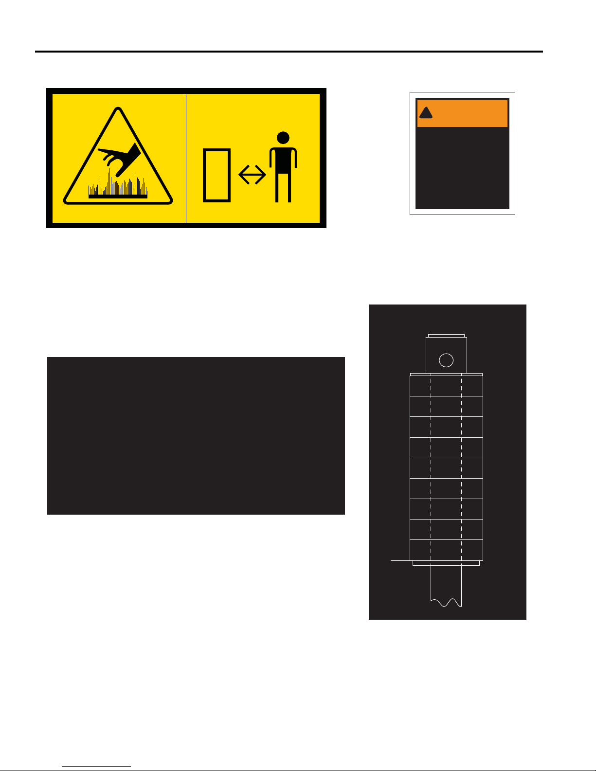
3 DECALCOLMANIE
IMPORTANT
This machine uses GreensCare 68,
a biodegradable hydraulic fluid.
(Order 5003103 for 5 gal. pail)
Use of 10W30 is an approved
alternate fluid.
Use will compromise all
biodegradable properties of
GreensCare 68 hydraulic fluid.
4108880
!
WARNING
This structure's
proctective capability
may be impaired by
structural damage,
overturn, or alteration.
If any of these
conditions occur, this
structure must be
replaced.
5003597
Avvertenza
Per evitare ustioni non toccare la marmitta o
il relativo riparo. Le temperature possono
superare 66 °C.
4199140
CUT
HEIGHT
W/ 1/2
SPACERS
CUT
HEIGHT
W/ 1/4
SPACER
it-16
5-1/4
4-3/4
4-1/4
3-3/4
3-1/4
2-3/4
2-1/4
1-3/4
1-1/4
3/4
5
4-1/2
4
3-1/2
3
2-1/2
2
1-1/2
1
4133609
Page 73
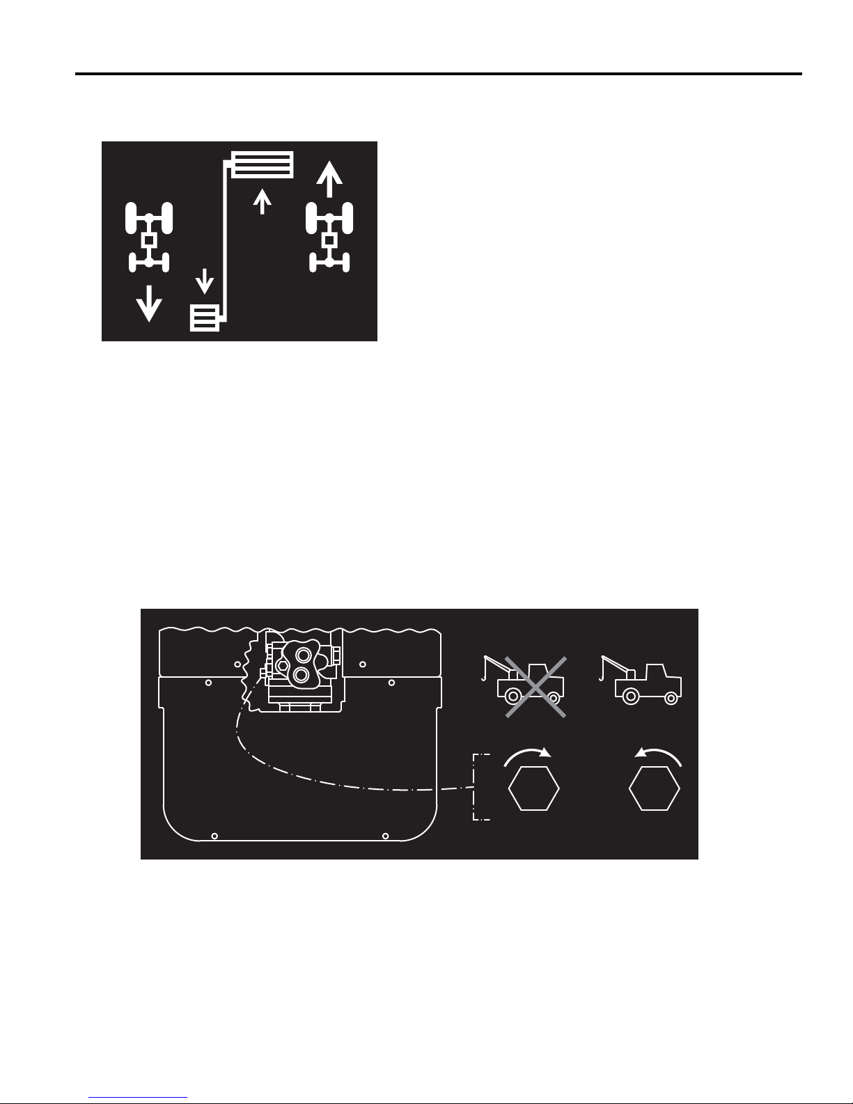
Valvola di traino
Il veicolo puòNormale
servizio essere trainato
(chiusa) (aperta)
Pedale della trazione
Retromarcia Marcia avanti
DECALCOLMANIE 3
3008521
3008682
it-17
Page 74
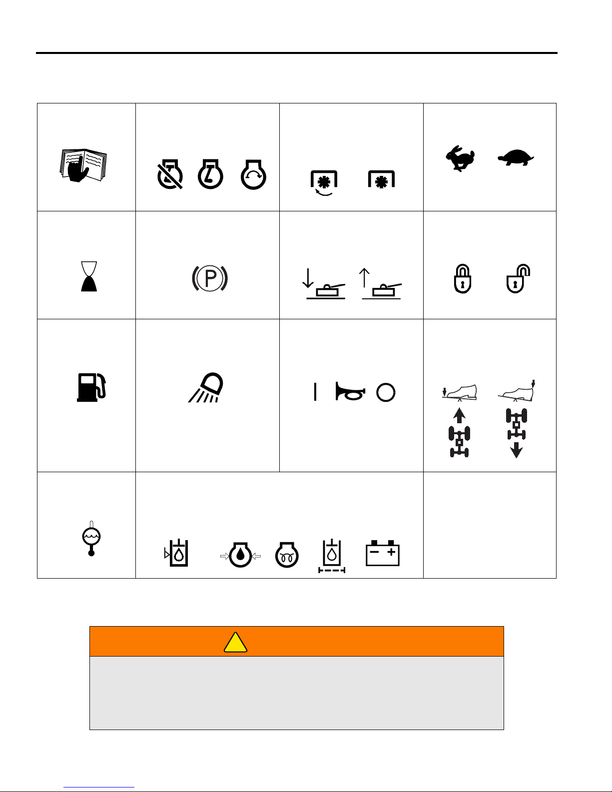
4 COMANDI
Leggere il
Alta Bassa
Manetta
Blocca Sblocca
Avanti Indietro
Moto
Controllo corsa
(Spento) (In moto) (Avvio)
Motore
Freno di stazionamento
Temperatura
refrigerante
Carburante
Tosaerba
Abbassa Solleva
Luci di servizio
Contaore
Interruttore livello dell’olio
Acceso Spento/Prova
Pressione
olio motore
Candele
di
riscalda
mento
Filtro olio
impianto
idraulico
Carica
della
batteria
Spie
Livello
impianto
idraulico
D
manuale
PDF
ON
(Acceso)
OFF
(Spento)
OFF RUN START
!
4 COMANDI
4.1 ICONE ___________________________________________________________________
Non mettersi alla guida del tosaerba senza aver prima letto il Manuale d’uso e di sicurezza e
aver imparato a utilizzare correttamente tutti i comandi.
Prendere confidenza con le icone riportate nella parte in alto della pagina e con il loro
significato. Individuare ubicazione e impiego dei vari comandi e indicatori prima di mettere in
funzione il tosaerba.
it-18
AVVERTENZA
Page 75
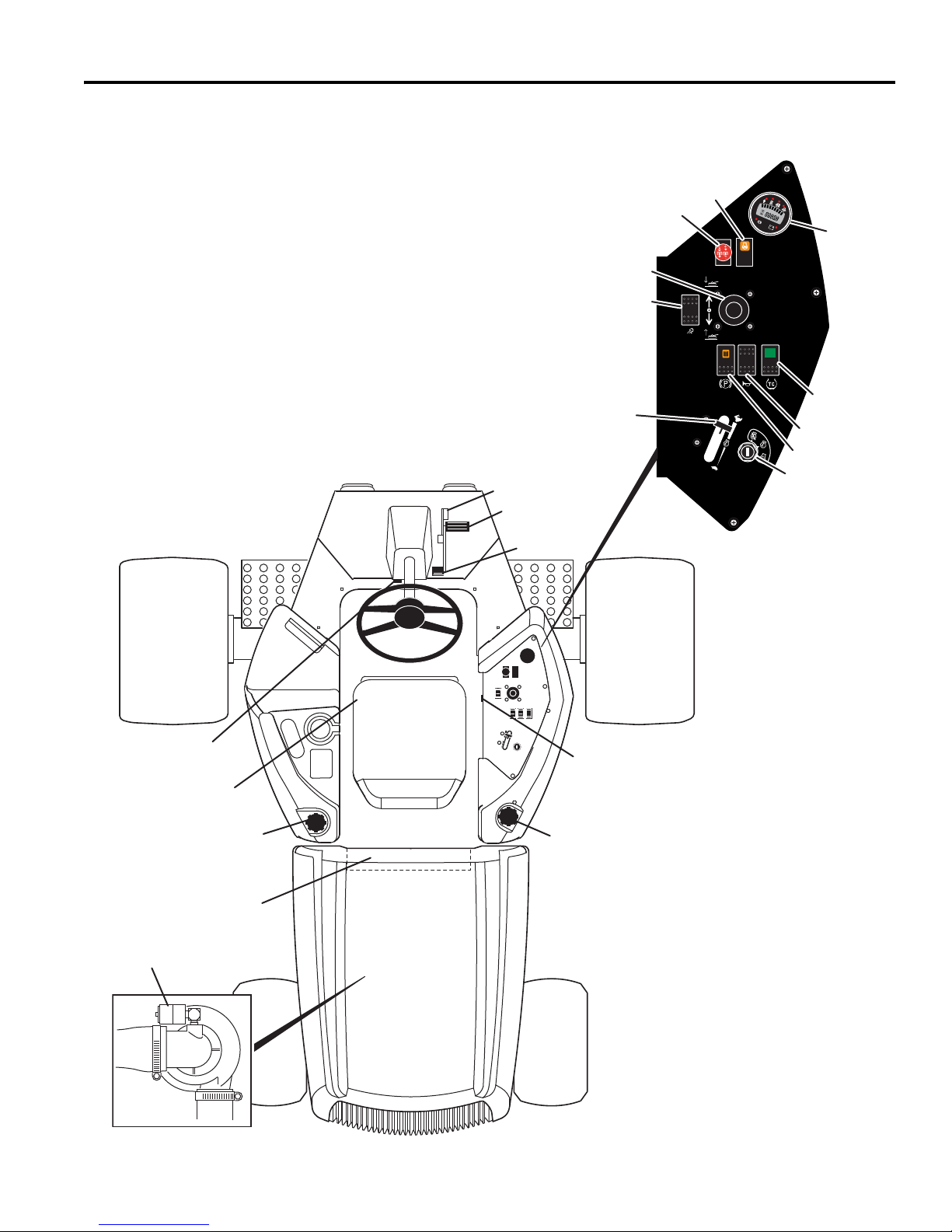
COMANDI 4
A
E
M
U
F
J
S
V
C
B
G
K
L
R
D
H
P
N
T
W
P
E
F
A Leva per inclinazione
volante
B Limitatore di velocità per la
tosatura
C Pedale di trazione - Avanti
D Pedale di trazione -
Indietro
E
Regolazione del sedile
F Tappo/Asta di livello dell’olio
idraulico
G Indicatore del filtro dell’aria
H Tappo del carburante
J Allarme
K Controller/Fusibili
L Interruttore dell’avvisatore
acustico
M Spia della candela a
incandescenza
N Leva per sollevamento
tosaerba
P Interruttore della presa di
forza
R Interruttore delle luci
S Interruttore del controllo
della trazione
T Acceleratore del motore
U Interruttore di accensione
V Indicatore combinato
W Interruttore del freno
4.2 COMANDI ________________________________________________________________
it-19
Page 76
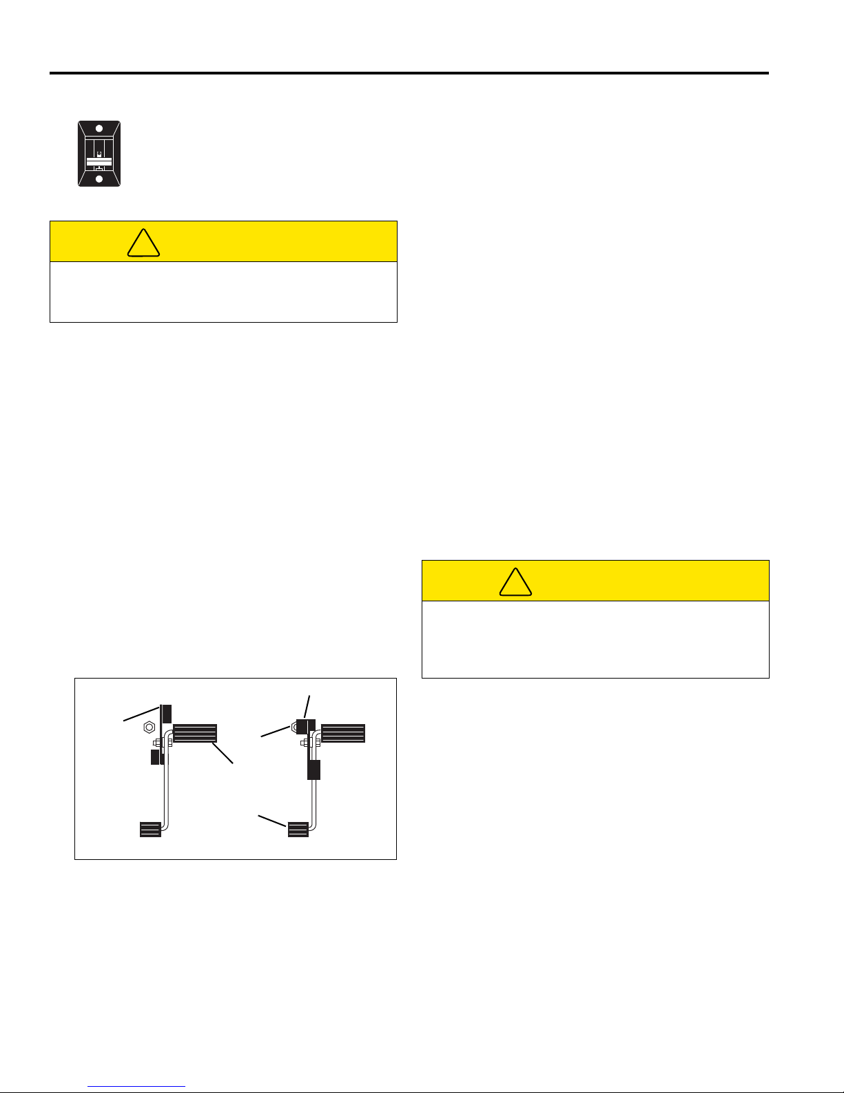
4 COMANDI
!
B
3
Velocità di avanzamento
Velocità di tosatura
B
1
B
2
C
D
!
A. Leva per inclinazione volante
Sollevare la leva per sbloccare il piantone
dello sterzo, quindi inclinare il piantone fino
a raggiungere un posizionamento ottimale.
Rilasciare la leva per bloccare nuovamente
il piantone dello sterzo.
ATTENZIONE
Non regolare mai lo sterzo mentre il tosaerba è in
movimento. Prima di effettuare la regolazione,
arrestare l'unità e inserire il freno di stazionamento.
B. Limitatore di velocità per la tosatura
Limita la velocità di avanzamento dell'unità durante
la tosatura. Per ridurre la velocità, premendo il
pedale di trazione in avanti, ruotare la leva fino a
raggiungere la vite di fermo (B
avanzare alla massima velocità, spostare la leva
nella posizione illustrata (B
può essere regolata per impostare specifiche
velocità di tosatura. Vedere Sezione 8.2.
C. Pedale di trazione - Avanti
Premere la parte anteriore del pedale per fare
procedere in avanti il mezzo. Rilasciare il pedale per
fare rallentare il tosaerba e fermarlo.
) sul pianale. Per
1
). La vite di fermo (B2)
3
F. Tappo / Asta di livello dell’olio idraulico
Riempire fino al segno indicato sull'asta di livello
utilizzando fluido idraulico pulito a macchina fredda.
Non riempire eccessivamente.
G. Indicatore del filtro dell’aria
Indica la condizione del filtro dell'aria del motore.
Pulire e sostituire il filtro dell'aria quando nella
finestrella trasparente dell'indicatore compare una
banda rossa. Vedere Sezione 7.4.
H. Tappo del carburante
Riempire il serbatoio del carburante con gasolio 2D
con numero di cetano minimo pari a 45. Vedere
Sezione 5.11.
J. Allarme
L'allarme, insieme alle spie dell'indicatore combinato
(V), si attiva per segnalare all'operatore condizioni
che richiedono attenzione immediata. Vedere
Sezione 4.4.
K. Controller/Fusibili
Il controller è situato sotto il cofano posteriore, subito
dietro il sedile dell'operatore. È dotato di spie per
agevolare il monitoraggio e la risoluzione dei
problemi dell'impianto elettrico del tosaerba.
Sul controller sono montati due fusibili a lama. Per
sostituire i fusibili, rimuovere il pannello di accesso.
D. Pedale di trazione - Indietro
Premere la parte posteriore del pedale per far
muovere il mezzo in retromarcia. Rilasciare il pedale
per fare rallentare il tosaerba e fermarlo. Prima di
invertire la direzione di marcia, lasciare che il
tosaerba si fermi del tutto.
E. Regolazione del sedile
Tirare verso l'esterno la leva di sinistra per regolare il
sedile in avanti o indietro. Per regolare la tensione
della molla sotto al sedile, girare la manopola di
regolazione posizionata davanti al sedile.
ATTENZIONE
Gli interventi sull'impianto elettrico devono essere
eseguiti da un tecnico qualificato. Prima di sostituire i
fusibili, spegnere il tosaerba e rimuovere la chiave
dall'interruttore di accensione.
Figura 4A
it-20
Page 77
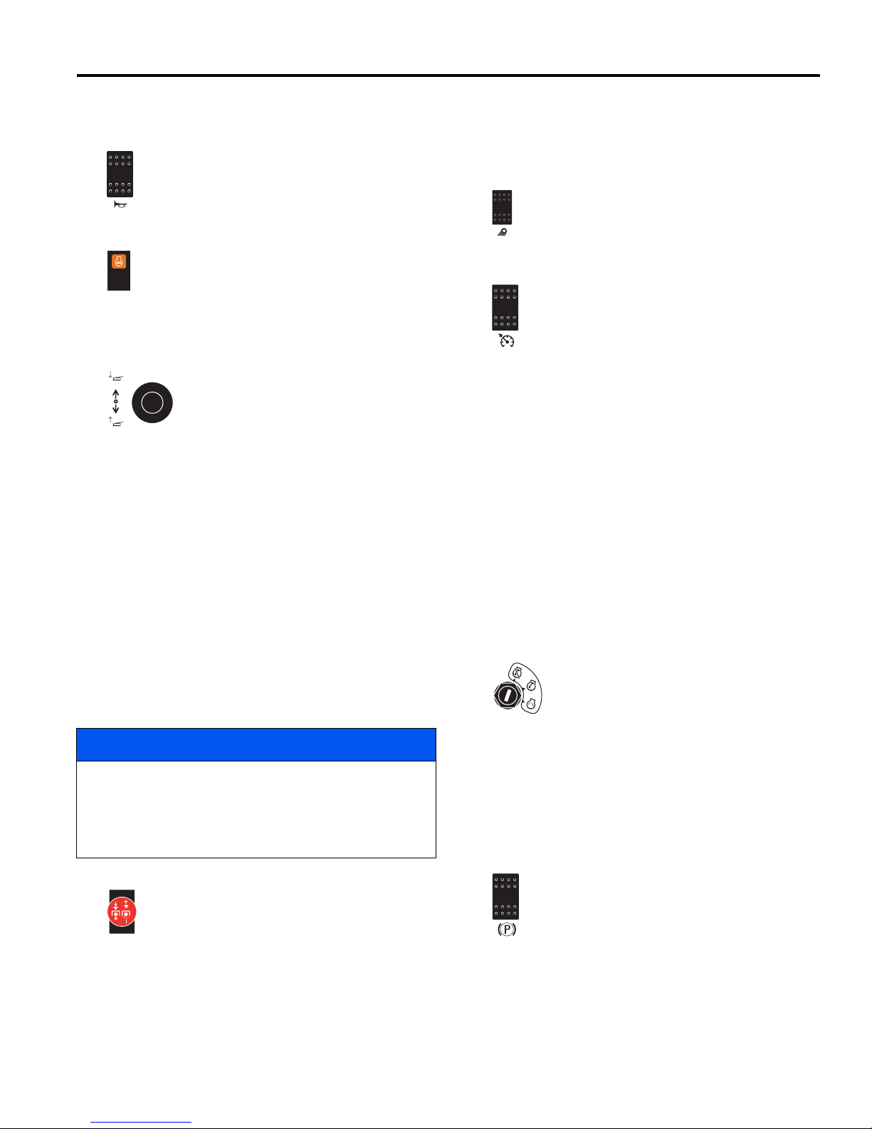
COMANDI 4
4.3 PLANCIA COMANDI________________________________________________________
L. Interruttore dell’avvisatore acustico
Questo interruttore permette di attivare
l'avvisatore acustico.
M. Spie luminose
Quando l'interruttore di accensione (U) viene
portato in posizione RUN, l'accensione della
spia della candela a incandescenza indica che
le candele a incandescenza sono alimentate.
Attendere lo spegnimento della spia per avviare il
motore.
N. Leva per sollevamento tosaerba
Questa leva permette di alzare e
abbassare i tosaerba e di impostare la
modalità automatica o manuale .
Spingere la leva in avanti per
abbassare i tosaerba e tirarla indietro
per sollevarli.
Modalità manuale - Abbassare l'interruttore di
tosatura (Q) in posizione OFF. In questa posizione
tutti i tosaerba si alzano o si abbassano quando
l'operatore aziona la leva di sollevamento.
Modalità automatica - Alzare l'interruttore di
tosatura (Q) in posizione ON. Nella modalità
automatica, i tosaerba si abbassano e si avviano
automaticamente semplicemente muovendo in
avanti per un attimo la leva di sollevamento. In
questa modalità i tosaerba si alzano in posizione di
“taglio incrociato” (crosscut) soltanto muovendo
indietro per un attimo la leva di sollevamento.
Per sollevare i tosaerba in posizione di trasferimento,
trattenere la leva finché i tosaerba non sono
completamente alzati.
AVVISO
Durante il ciclo di sollevamento o abbassamento in
modalità automatica (della durata di circa 3 secondi),
muovendo la leva di sollevamento si disattivano tutti i
tosaerba e viene attivata la modalità manuale per la
posizione selezionata.
P. Interruttore della presa di forza
L’interruttore della presa di forza è costituito
da una manopola a due posizioni che
permette di innestare e disinnestare i
tosaerba. Viene utilizzato anche per
impostare la leva di sollevamento tosaerba
(P) in modalità manuale o automatica. Durante
l'avviamento del tosaerba, portare l’interruttore della
presa di forza nella posizione di disinnesto (giù).
Quando l'interruttore della presa di forza si trova
nella posizione di innesto (SU), il sistema di controllo
della trazione viene attivato automaticamente e la
leva di sollevamento viene spostata in modalità
automatica.
R. Interruttore delle luci
Controlla il funzionamento dei fari da lavoro.
Premere la parte anteriore dell’interruttore per
accendere i fari e quella posteriore per
spegnerli.
S. Controllo della trazione
Premere l’interruttore per attivare il sistema di
controllo della trazione. Questo sistema
riduce il carico sui piatti di taglio,
trasmettendo impulsi al circuito di
sollevamento e trasferendo il peso al
tosaerba. La riduzione del carico migliora la
trazione, ma può causare oscillazioni dei piatti di
taglio e produrre una tosatura irregolare. La spia
dell'interruttore si accende quando il sistema è attivo.
Premere nuovamente l’interruttore per disattivare il
controllo della trazione. In questo modo, la trazione si
riduce, ma migliora il contatto tra piatti di taglio e
terreno.
Il sistema di controllo della trazione viene attivato
automaticamente quando l'interruttore della presa di
forza si trova nella posizione di innesto (SU).
Premere l'interruttore del controllo della trazione per
disattivare il controllo della trazione.
T. Acceleratore del motore
Regola il regime di rotazione del motore. Mantenere
la macchina alla massima accelerazione durante il
normale funzionamento.
U.Interruttore di accensione
L’interruttore di accensione ha tre
posizioni: OFF - RUN (ON) - START
[SPENTO - IN MARCIA (ACCESO) AVVIAMENTO]. In posizione RUN il
controller è attivo e i circuiti di ingresso e
uscita sono monitorati. Vedere la Sezione 5.4 e
Sezione 9.2.
V. Indicatore combinato
Mostra il livello del carburante, le ore di
funzionamento e gli avvisi relativi al tosaerba. Vedere
la Sezione 4.4.
W.Interruttore del freno di stazionamento
Per innestare il freno di stazionamento, far
scorrere in avanti il fermo e premere la parte
superiore dell'interruttore. Si accende la spia
del freno di stazionamento sull'indicatore (V).
Quando il freno di stazionamento è innestato,
i cilindri di taglio sono disattivati.
Per disinnestare il freno di stazionamento, premere
la parte posteriore dell'interruttore. Si spegne la spia
del freno di stazionamento sull'indicatore combinato.
NOTA: il tosaerba non si avvia se l’interruttore del
freno di stazionamento è in posizione di disinnesto.
it-21
Page 78
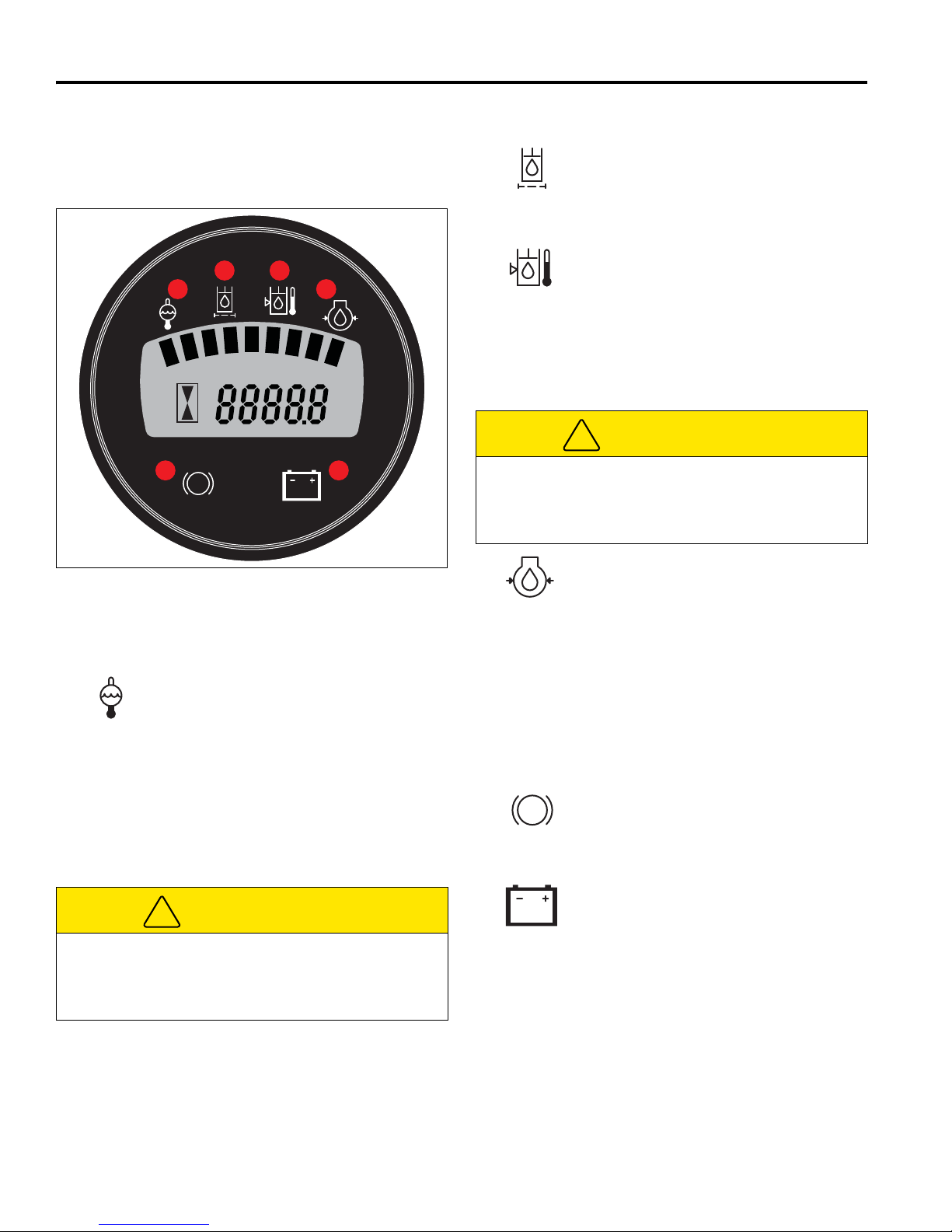
4 COMANDI
P
EF
!
!
P
4.4 SPIE DI SEGNALAZIONE PER L'OPERATORE __________________________________
L'indicatore combinato mostra ore di funzionamento,
livello del carburante e spie di segnalazione relative alle
condizioni del tosaerba.
Figure 4B
4.4.1 Spie luminose ____________________
L’indicatore combinato è provvisto di sei spie luminose
associate al funzionamento del sistema.
Spia della temperatura del refrigerante:
la spia rossa della temperatura del
refrigerante indica che la temperatura del
refrigerante ha superato i 110°C. Spegnere
immediatamente il motore. Rimuovere
eventuali detriti, come foglie ed erba
falciata, che possono limitare il flusso d’aria
attraverso la griglia posteriore e il radiatore.
Se il motore mantiene una temperatura
troppo elevata, riportare il tosaerba in
un'area di servizio.
ATTENZIONE
Il refrigerante dei motori diesel è sotto pressione.
Spegnere il motore e lasciare raffreddare il fluido
prima di controllarne il livello o di rabboccare il
radiatore con altro refrigerante.
Spia del filtro dell’olio idraulico: la spia
rossa del filtro dell'olio indica che il filtro
idraulico deve essere sostituito. Riportare il
tosaerba a un’area di servizio il più presto
possibile per sostituire i filtri.
Spia di livello dell’olio idraulico: la spia
rossa di livello dell'olio idraulico indica che il
livello del fluido nel serbatoio idraulico è
troppo basso. Spegnere immediatamente il
tosaerba. Ispezionare il tosaerba per
accertarsi che non vi siano tracce di perdite
in prossimità di raccordi, tubi e componenti
idraulici. Riportare il tosaerba all'area di
servizio per la manutenzione.
ATTENZIONE
Il fluido idraulico è sotto pressione. Spegnere il
tosaerba e lasciare raffreddare il fluido prima di
controllarne il livello o di rabboccare il serbatoio
idraulico con altro olio.
Spia della pressione dell’olio motore: la
spia rossa della pressione dell'olio motore
indica che la pressione dell'olio motore è
troppo bassa. Spegnere immediatamente il
motore. Controllare il livello dell’olio nel
motore. Se la spia dell’olio rimane accesa
anche quando il livello dell’olio è corretto,
spegnere il motore e trainare o rimorchiare
il tosaerba fino a un’area di servizio. MAI
usare il motore se la spia dell'olio è accesa,
in quanto il motore potrebbe subire gravi
danni.
Spia del freno di stazionamento: la spia
rossa del freno di stazionamento indica che
il freno di stazionamento è inserito. Mai
premere il pedale di trazione quando il
freno di stazionamento è inserito.
Spia della batteria: la spia rossa della
batteria indica che la tensione è scesa sotto
11,5 V per un minuto. Riportare il tosaerba
in un'area di servizio e controllare la
batteria e i relativi sistemi di ricarica.
it-22
Page 79
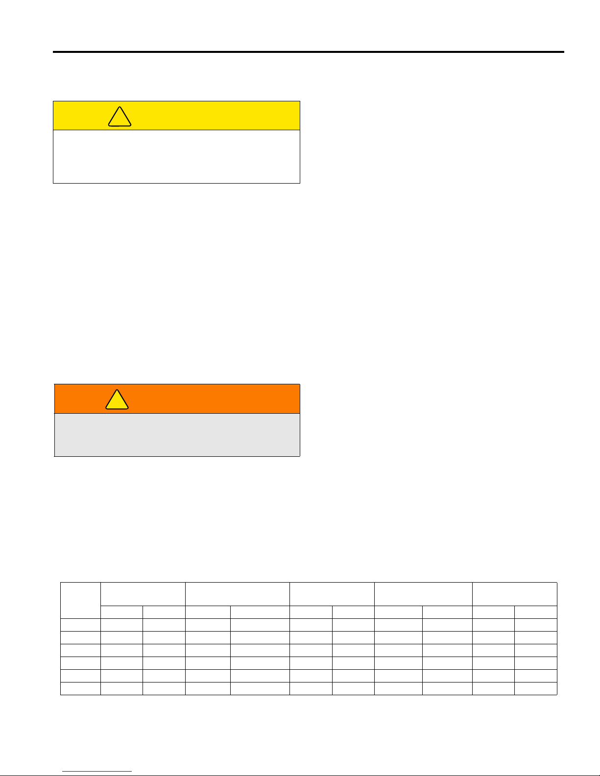
FUNZIONAMENTO 5
!
!
5 FUNZIONAMENTO
5.1 ISPEZIONE GIORNALIERA __________________________________________________
2. Controllare l’alimentazione del carburante, il livello del
ATTENZIONE
Effettuare l’ispezione giornaliera soltanto quando il
motore è spento e tutti i fluidi sono freddi. Abbassare le
tosatrici a terra, innestare il freno di stazionamento,
fermare il motore e rimuovere la chiave d’accensione.
1. Effettuare un’ispezione visiva di tutta l’unità, verificare la
presenza di segni di logorio, unità allentate e compo
nenti assenti o danneggiati. Controllare la presenza di
perdite di carburante o di olio per garantire che le con
nessioni siano serrate e che i tubi rigidi e flessibili siano
in buone condizioni.
5.2 SISTEMA DI INTERBLOCCO _________________________________________________
-
-
refrigerante nel radiatore, l’olio nella coppa e
l’indicatore del pulitore dell’aria. Tutti i fluidi devono
trovarsi al marchio di livello pieno a motore freddo.
3. Accertarsi che tutte le tosatrici siano regolate alla
stessa altezza di taglio.
4. Controllare se le gomme sono correttamente gonfie.
5. Controllare il sistema microinterruttori di sicurezza.
Nota: Per informazioni più dettagliate su
manutenzione, regolazioni e sulle tabelle di
manutenzione/lubrificazione, vedere le Sezioni 6, 7 e
8.
1. Il sistema di interblocco impedisce l’avviamento del
motore a meno che il freno di stazionamento sia
inserito, il pedale di trazione sia in folle e l'interruttore
della presa di forza sia in posizione OFF (disinnestato).
Inoltre, il sistema arresta il motore se l'operatore si alza
dal sedile con l'interruttore della presa di forza su ON
(innestato), il pedale di trazione non in folle o il freno di
stazionamento disinserito.
AVVERTENZA
Non utilizzare mai l'attrezzatura se il sistema di
interblocco è disattivato o non funzionante. Non
scollegare o bypassare alcun interruttore.
2. Eseguire le seguenti prove per accertare il corretto
funzionamento del sistema di interblocco. Interrompere
il test e far controllare e riparare il sistema qualora una
qualsiasi delle seguenti prove dovesse fallire:
? il motore non si avvia durante la prova 1;
? Il motore si avvia durante la prova 2, 3 o 4;
? il motore continua a funzionare durante la prova 5 o
6.
Controllo del sistema microinterruttori di sicurezza
3. Consultare la tabella qui in basso per ciascuna prova e
seguire i segni di spunta (). Spegnere il motore tra
una prova e l'altra.
Prova 1: rappresenta la normale procedura di
avviamento. L’operatore è seduto, il freno di
stazionamento è inserito, i piedi dell’operatore non sono
sui pedali e l'interruttore della presa di forza è su OFF. Il
motore deve avviarsi.
Prova 2: il motore non deve avviarsi se l'interruttore
della presa di forza è in posizione ON.
Prova 3: il motore non deve avviarsi se il freno di
stazionamento è disinserito.
Prova 4: il motore non deve avviarsi se viene premuto il
pedale di trazione.
Prova 5: avviare il motore come di consueto, quindi
porre l'interruttore della presa di forza in posizione ON e
alzarsi dal sedile.
Prova 6: avviare il motore come di consueto, quindi
disinserire il freno di stazionamento e alzarsi dal sedile.
Prova
1
2
3
4
5
6
Operatore seduto Freno di
Sì No Innest. Disinnest. Sì No Acceso Spento Sì No
Sollevare il proprio peso dal sedile. Le unità di falciatura dovranno arrestarsi entro sette (7) secondi.
stazionamento
Pedale della
trazione in folle
Interruttore della PDF Il motore parte
it-23
Page 80
5 FUNZIONAMENTO
!
!
!
!
5.3 PROCEDIMENTI DI FUNZIONAMENTO ________________________________________
AVVERTENZA
Questo tosaerba è dotato di struttura di protezione dell’operatore (ROPS). Le cinture di sicurezza devono essere sempre
allacciate quando si aziona un tosaerba dotato di ROPS. Tenere le cinture di sicurezza sempre aderenti. NON usare le
cinture di sicurezza su tosaerba sprovvisti di ROPS.
In caso di capovolgimento del tosaerba, tenere stretto il volante; non cercare di saltare fuori o di lasciare il sedile.
ATTENZIONE
Per evitare possibili lesioni, indossare sempre occhiali protettivi, scarpe o stivali da lavoro in pelle, elmetto e paraorecchi.
1. Non avviare mai il motore se l’operatore non è
seduto sul sedile.
l’operatore o altre persone si trovano dietro un
condotto di scarico.
2. Non fate mai funzionare il motore in un ambiente
chiuso.
3. Tenete mani e piedi a debita distanza dalle parti in
movimento e dagli apparati di taglio. Se possibile,
non eseguite regolamenti se il motore è in moto.
4. Non azionare il tosaerba o gli accessori con
componenti allentati, danneggiati o assenti. Tagliare
l’erba, se possibile, quando è asciutta.
5. Tagliare prima in un’area di prova per familiarizzarsi
con il funzionamento del tosaerba e delle leve di
comando.
6. Studiare l’area per determinare il migliore e più
sicuro procedimento di funzionamento. Considerare
l’altezza dell’erba, il tipo di terreno e le condizioni
della superficie. Ciascuna condizione richiede
determinate regolazioni o precauzioni.
7. Non indirizzare mai lo scarico del materiale verso gli
astanti, né consentire a persone di avvicinarsi alla
macchina mentre questa è in funzione. Il
proprietario/l’operatore è responsabile delle lesioni
inflitte agli astanti e/o di eventuali danni alle loro
proprietà.
Non avviate il motore se
ATTENZIONE
Prima di procedere con la falciatura, raccogliere tutti i
detriti quali sassi, giocattoli e fili che potrebbero essere
espulsi dalla macchina. Prestare la massima attenzione
entrando in una zona nuova. Operare sempre a una
velocità che consenta di mantenere il pieno controllo del
tosaerba.
8. Usare discrezione quando si effettua la di tosatura
vicino alle aree ricoperte da ghiaia (superficie
stradale, aree di parcheggio, sentieri per carri, ecc.).
I sassi scaricati dalla macchina possono provocare
gravi lesioni agli astanti e/o danni alle
apparecchiature.
9. Durante le pause di tosatura girate sempre
l’interruttore della PDF in posizione OFF (Spento)
per fermare le lame.
10. Scollegare i motori di comando e sollevare le bobine
quando si attraversano sentieri e strade. Prestare
attenzione al traffico.
11. Fermare e ispezionare l’apparecchiatura per
verificare immediatamente la presenza di danni
dopo aver colpito un’ostruzione o se la macchina
inizia a vibrare in modo anomalo. Far riparare
l’apparecchio prima di riprendere l’operazione.
AVVERTENZA
Prima di pulire, regolare o riparare questo apparecchio
disinnestare sempre tutti i comandi, abbassare gli
attrezzi a terra, innestare il freno di stazionamento,
fermare il motore e rimuovere la chiave dall’interruttore
d’accensione per prevenire infortuni.
12. Rallentare e usare particolare attenzione sulle
superfici inclinate. Leggere la Sezione 5.10.
procedere con cautela nei punti di considerevole
dislivello.
13. Controllare dietro e in basso prima di fare la
retromarcia per accertarsi che il sentiero sia
sgombro. Usare attenzione in procinto di angoli
ciechi, cespugli, alberi o altri oggetti che possono
oscurare la visibilità.
14. Non usare mai le mani per pulire le unità di taglio.
Usare una spazzola per rimuovere l’erba tagliata
dalle lame. Le lame sono estremamente affilate e
possono causare gravi lesioni.
it-24
Page 81

FUNZIONAMENTO 5
!
5.4 AVVIAMENTO _____________________________________________________________
Attendere che la spia delle candele di riscaldamento
AVVISO
IMPORTANTE: Non usare fluidi per assistere
l’avviamento. L’uso di fluidi di questo genere nel
sistema di presa dell’aria può essere potenzialmente
esplosivo o può causare una condizione di motore “a
regime fuori giri” con gravi danni al motore.
AVVERTENZA
Per evitare infortuni, sedetevi al posto di guida e,
prima di avviare il motore, inserite il freno di
stazionamento, mettete in folle il pedale della
trazione, e il commutatore della PDF in posizione OFF
(Spento).
1. Sedersi al posto di guida e assicurarsi che l’interrut-
tore della PDF (P) sia OFF (Spento) (in posizione
centrale) e il freno di stazionamento (W) inserito.
Togliere i piedi dai pedali. Indossare la cintura di
sicurezza quando si è alla guida di trattori dotati di
ROPS.
2. Portare la manetta (T) a metà corsa.
3. Girare l’interruttore d’accensione (U) in posizione
ON (Acceso) (
Nota: A questo punto, le spie sul pannello strumenti
(V, M) si accenderanno. Verificare che spie siano
funzionanti.
).
(M) si spenga e girare la chiave d’accensione (U) in
posizione
appena il motore si avvia. Lasciare 30 secondi tra un
tentativo di accensione e l’altro, per dar modo al
motorino d’avviamento di raffreddarsi.
Una volta avviato il motore, le spie dovrebbero
spegnersi tutte. Attendere che il motore si scaldi
prima di portare il numero di giri a regime di
funzionamento.
START (Avvio) ( ). Rilasciarla non
M
P
T
E
F
P
V
W
U
AVVISO
Non tenere la chiave d’accensione in posizione
START (Avvio) per più di 10 secondi per volta. Dopo
10 secondi il circuito d’accensione si spegne e deve
essere azzerato riportando la chiave in posizione OFF
(Spento).
Figura 5A
5.5 ARRESTO / PARCHEGGIO __________________________________________________
Per l’arresto:
Togliete il piede dal pedale della trazione. Il tosaerba
frena automaticamente quando il pedale della trazione
ritorna in FOLLE. Inserite sempre il freno di
stazionamento, spegnete il motore e togliete la chiave di
accensione prima di lasciare la postazione di guida per
qualsiasi motivo.
Parcheggio del tosaerba in normali condizioni
1. Disinnestate il commutatore della PDF (Q), quindi
sollevate e bloccate gli attrezzi in posizione di
trasporto e allontanatevi dall’area di lavoro.
2. Dirigetevi verso un’area pianeggiante in cui
parcheggiare.
a. Rilasciate il pedale della trazione per fermare
completamente il tosaerba.
b. Disinnestare tutte le trasmissioni, abbassare al
suolo gli attrezzi, azionare il freno di stazionamento e portare l'acceleratore al minimo.
3. Innestare il freno di stazionamento, fermare il
motore e rimuovere sempre la chiave d’accensione.
Se insorge un’emergenza e il tosaerba deve essere
parcheggiato nell’area di operazione, seguire le linee di
guida delineate dal responsabile che sovrintende i
terreni. Se il tosaerba è parcheggiato su un terreno in
pendenza, bloccare le ruote con tacchi.
it-25
Page 82

5 FUNZIONAMENTO
!
5.6 GUIDA / TRASPORTO ______________________________________________________
Leggere e seguire tutti gli avvisi di sicurezza contenuti in
questo manuale quando si guida o si trasporta il
tosaerba. Quando si fa la retromarcia controllare alle
proprie spalle che il percorso sia libero.
IMPORTANTE: Se il tosaerba viene utilizzato su
strade pubbliche, deve essere conforme alle leggi e
ai regolamenti locali vigenti. Richiedere i regolamenti
e i requisiti degli apparecchi alle autorità locali.
Sollevamento dei tosaerba in posizione di trasporto:
Spostate il commutatore della PDF al centro, in posizione
OFF (Spento). Tirate indietro la leva dei tosaerba e
tenetela in questa posizione finché i tosaerba non sono
sollevati ed i bracci di sollevamento non si trovano nella
posizione di trasporto, completamente sollevati.
IMPORTANTE: Durante il trasporto del tosaerba il
commutatore di tosatura deve essere al centro, in
posizione OFF (Spento).
5.7 FALCIATURA _____________________________________________________________
sollevano in posizione trasversale. Per sollevare i
AVVERTENZA
Per evitare gravi infortuni, quando le lame girano
tenete mani, piedi e indumenti lontano dagli apparati
di taglio.
NON pulite MAI gli apparati di taglio con le mani.
Rimuovete l’erba tagliata dalle lame con una
spazzola. Le lame possono essere affilate e ferirvi.
NON usate i tosaerba se sono privi dei condotti di
scarico posteriori o della piastra di mulching.
La falciatura
1. Portare l’interruttore della presa di forza in posizione
ON (su). Questa azione fa spostare la leva dei
tosaerba in modalità automatica e attiva
automaticamente il sistema di controllo della
trazione. [Vedere 4.3].
2. Premete momentaneamente in avanti la leva dei
tosaerba per abbassare i tosaerba. Quando gli
apparati di taglio sono abbassati, i tosaerba iniziano
automaticamente a girare.
3. Per sollevare i tosaerba, tirate indietro la relativa
leva e rilasciatela. I tosaerba si fermano e si
tosaerba in posizione di trasporto tenete la leva in
questa posizione finché i tosaerba non sono
completamente sollevati.
4. Premere l'interruttore del controllo della trazione (S)
per disattivare il controllo della trazione. [Vedere
4.3].
Tosate sempre con il motore alla massima.
Montaggio della piastra di mulching
Il condotto di scarico posteriore può essere sostituito
dalla piastra di mulching optional. Non azionate i
tosaerba se il condotto di scarico posteriore o la piastra
di mulching non sono montati.
1. Abbassate il commutatore della PDF in posizione
OFF, (Spento) abbassate i tosaerba al suolo, inserite
il freno di stazionamento e spegnete il motore.
2. Togliete i tre dadi che fissano il condotto di scarico
alla scocca dei tosaerba.
3. Togliete il condotto di scarico e montate la piastra di
mulching, fissandola con i tre dadi tolti in
precedenza. Conservate il condotto di scarico in un
luogo sicuro per utilizzarlo in un secondo tempo.
5.8 VELOCITÀ DI FALCIATURA _________________________________________________
La qualità della falciatura è migliore a velocità molto al di
sotto di quella di trasporto del tosaerba. La velocità di
falciatura impostata in fabbrica è di 10-11 km/h e
dovrebbe essere adatta alla maggior parte delle
condizioni di falciatura. Tuttavia, con un particolare tipo di
terreno, può rendersi necessario operare a velocità
diversa. Se sono necessarie delle regolazioni, consultare
la Sezione 8.2.
it-26
Page 83
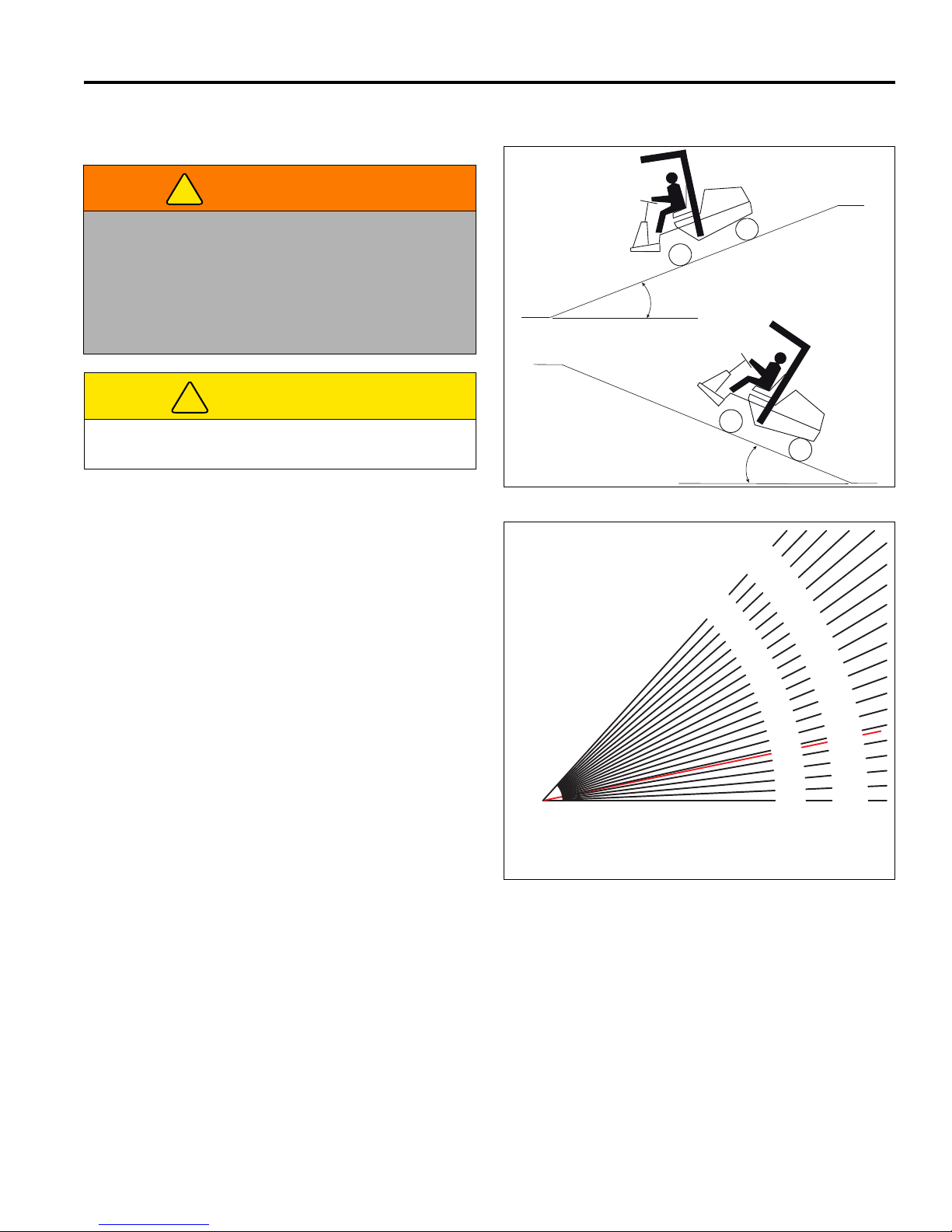
FUNZIONAMENTO 5
!
!
5.9 GUIDA IN PENDENZA ______________________________________________________
AVVERTENZA
Onde ridurre il rischio di ribaltamento, il metodo più
sicuro per tosare su superfici in pendenza e su
terrazzamenti è affrontare la pendenza frontalmente
(verticalmente) e non trasversalmente
(orizzontalmente). Evitare curve non necessarie,
15.7°
28%
Maximum
guidare a velocità ridotta e fare attenzione ai pericoli
nascosti.
ATTENZIONE
Non utilizzare questo tosaerba su pendenze superiori
a 15,7° o al 28%.
15.7°
28%
Maximum
Il tosaerba è stato progettato per avere buona stabilità e
trazione in normali condizioni di utilizzo; è tuttavia
necessario guidare con cautela sulle superfici in
pendenza, specialmente se l'erba è bagnata. L’erba
bagnata, infatti, riduce la trazione e il controllo dello
sterzo.
1. Lavorare sempre con il motore al massimo regime di
rotazione, ma ridurre la velocità di avanzamento per
mantenere una frequenza di taglio adeguata.
2. Attivare il controllo della trazione (S) quando
necessario per migliorare la distribuzione dei pesi
tra i piatti di taglio e il tosaerba. [Vedere 4.3].
3. Se il tosaerba tende a slittare o gli pneumatici
lasciano segni sul manto erboso, portare il tosaerba
su una traiettoria meno ripida finché non si recupera
trazione o gli pneumatici non smettono di lasciare
segni sull’erba.
4. Se il tosaerba continua a slittare o lascia segni sul
manto erboso, la pendenza è troppo ripida per
garantire la sicurezza dell'operazione. Interrompere i
tentativi di scalata del pendio e indietreggiare
lentamente.
5. Quando si scende da una superficie in forte
pendenza, abbassare sempre gli attrezzi al suolo
per ridurre il rischio di ribaltamento del tosaerba.
Per massimizzare la trazione, mantenere sempre la
giusta pressione degli pneumatici.
Anteriori..................... 1,10 bar
Posteriori...................0,86 bar
Gradi arrotondati al multiplo di 1/4° più vicino
Pendenza
100%
Inclinazione generale del terrapieno stradale: 45°
Cotica erbosa in massima pendenza: 31°
Pendenza tetto medio: 19-1/4°
Massima pendenza strade di 2a classe: 4-1/2°
Superstrada o strada a pedaggio: 1-3/4°
95%
90
Gradi
%
%
85
80
75%
Figura 5B
45°
-1/2°
3
4
42°
40-1/4°
38-3/4°
36-3/4°
35°
%
55%
50
45%
%
40%
35%
3
25%
20%
0%
15%
10%
5%
0%
33°
31°
28-3/4°
26-1/2°
24-1/4°
21-
19-1/4°
/4°
3
16-3/4°
14°
11-1/4°
8-1/2°
5-3/4°
2-3/4°
0°
%
%
70
65
60%
Figura 5C
it-27
Page 84
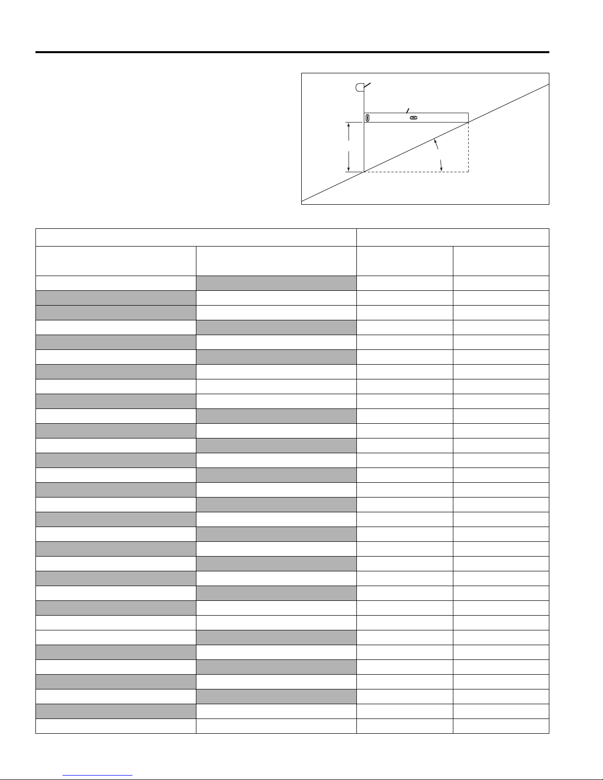
5 FUNZIONAMENTO
C
A
B
D
Come calcolare una pendenza:
Attrezzi necessari:
Livella (A) lunga 1 metro.
Metro a nastro (B).
Posizionare la livella (A) in orizzontale e misurare la
distanza (C) con il metro a nastro (B). Utilizzare la tabella
per calcolare l'angolo o la percentuale di pendenza della
superficie (D).
Altezza (C) Risultato (D)
Figura 5D
Pollici con livella da 1 iarda (A)
3
6
7.5
9 250 14 25.0
10
11
12
13
14
15
16
18 500 26.6 50.0
20
25
30
36 1000 45.0 100
it-28
Millimetri con livella da 1 metro
(A)
100 5.7 10.0
150 8.5 15
200 11.3 20.0
225 12.7 22.5
275 15.4 27.5
300 16.7 30.0
325 18.0 32.5
350 19.3 35.0
375 20.6 37.5
400 21.8 40.0
425 23.0 42.5
475 25.4 47.5
600 31.0 60.0
800 38.7 80.0
900 42.0 90
Pendenza in gradi Pendenza %
4.8 8.3
9.5 16.7
11.8 20.8
15.5 27.8
17.0 30.6
18.4 33.3
19.9 36.1
21.3 38.9
22.6 41.7
24 44.4
29.1 55.6
34.8 69.4
39.8 83.3
Page 85
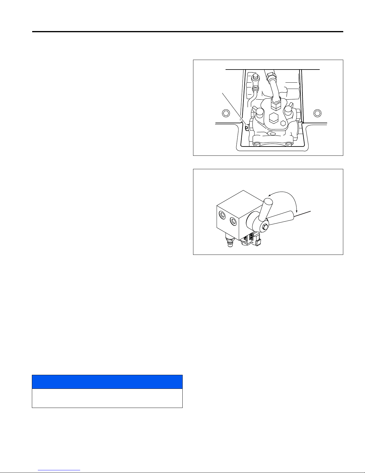
FUNZIONAMENTO 5
A
LF006
Brake released
for towing.
Brake engaged
(Normal operation)
B
5.10 RIMORCHIO / TRAZIONE____________________________________________________
Se il tosaerba riscontra dei problemi e deve essere
spento e rimosso dall’area, deve essere caricato su un
rimorchio per il trasporto. Se un rimorchio non è
disponibile, trainare l’unità lentamente per brevi distanze.
Prestare la massima attenzione nel caricare e scaricare il
tosaerba. Assicurare il tosaerba al rimorchio per
prevenire eventuali rollii e spostamenti durante il
trasporto.
Traino o trasporto a lunga distanza. Se dovete trainare
il tosaerba su strada, prima di ancorarlo al trailer chiudete
la valvola d’intercettazione del carburante e gonfiate i
pneumatici alla massima pressione indicata sul loro
fianco. In sede di rimozione dal trailer riducete la
pressione dei pneumatici [Vedere 5.10].
Prima di rimorchiare il tosaerba, aprire la valvola di traino
che ne permette lo spostamento senza avviare il motore
evitando di danneggiare le componenti idrauliche.
Figura 5E
La valvola di rimorchio (A) si trova sulla pompa di
comando sotto il cofano. Togliete la copertura dal
pavimento della macchina, davanti al sedile
dell’operatore. Per aprirla, inserire un perno nel foro
piccolo nella valvola di rimorchio e girare la valvola in
senso antiorario non più di un giro completo. Ruotare la
valvola di 90° in senso antiorario.
Ruotare la leva di rilascio del freno (B) in senso orario. La
leva di rilascio del freno si trova sotto il pannello a
pavimento, vicino all'attacco dell'assale anteriore destro.
Per rilasciare i freni, girare il volante verso destra (senso
orario) fino ad avvertire una certa resistenza.
Prima di rimorchiare il tosaerba, controllare che il gruppo
di falciatura sia sollevato. Se non è possibile sollevarlo,
rimuoverlo.
Una volta completata l’operazione di traino, chiudere
completamente la valvola e sostituire il coperchio.
Chiudere completamente la valvola di traino (A), ruotare
la leva di rilascio del freno (B) in senso orario e
riposizionare il pannello a pavimento al termine
dell'operazione di traino.
Figura 5F
AVVISO
Non superare i 3,2 km/h durante il traino ed evitare di
trainare il tosaerba su lunghe distanze.
it-29
Page 86

5 FUNZIONAMENTO
!
!
!
5.11 MANUTENZIONE GIORNALIERA _____________________________________________
IMPORTANTE: Informazioni più particolareggiate sulla
manutenzione, le regolazioni e le tabelle di
manutenzione/lubrificazione sono contenute nel
Manuale di manutenzione e parti.
1. Parcheggiare il tosaerba sopra una superficie piatta e
livellata. Abbassare completamente gli attrezzi a terra,
innestare il freno di stazionamento, fermare il motore e
rimuovere la chiave dall’interruttore di accensione.
2. Ingrassare e lubrificare tutti i punti se necessario. Per
prevenire incendi, lavare le unità di taglio ed il tosaerba
dopo ciascun uso.
a. Usate soltanto acqua dolce per la pulizia delle
vostre apparecchiature.
b. Non usare spruzzi ad alta pressione.
c. Non spruzzare l’acqua direttamente sul quadro
degli strumenti o su qualsiasi componente elettrico.
d. Non spruzzare acqua nella presa dell’aria di raffred-
damento né nella presa dell’aria del motore.
AVVISO
Non lavare un motore caldo o in funzione. Usare aria
compressa per pulire il motore e le alette del radiatore.
Pulire il tosaerba, il motore e le alette del radiatore con
aria compressa per ridurre il rischio di contaminazione
da umidità e corrosione.
5. Conservare il carburante in conformità ai regolamenti e
le raccomandazioni locali dei propri fornitori di
carburante.
6. Non riempite troppo, e non lasciate che il serbatoio si
svuoti completamente.
7. Ispezionare giornalmente i tubi e condotti idraulici.
Controllare la presenza di tubi bagnati o macchie d’olio
e sostituire tubi e condotti logori o danneggiati prima di
azionare la macchina.
AVVERTENZA
Per prevenire gravi infortuni causati dall’olio caldo ad alta
pressione, non usare mai le mani per verificare la
presenza di perdite d’olio, ma usare carta o cartone.
Il liquido idraulico in uscita sotto pressione può essere
sufficientemente forte da penetrare nella pelle. Se il
liquido viene iniettato nella pelle deve essere
chirurgicamente rimosso entro alcune ore da un medico
esperto nel trattamento di questo tipo di lesione, per
evitare la possibile insorgenza di gangrena.
8. Controllare l’olio del motore e l’olio idraulico all’inizio di
ciascuna giornata, prima di avviare il motore. Se il
livello dell’olio è basso, rimuovere il coperchio del
serbatoio dell’olio e rabboccare secondo le esigenze.
Non riempire eccessivamente.
3. Riempire il serbatoio di carburante del tosaerba al
termine di ciascuna giornata di funzionamento fino
segno di pieno sull’asta di livello.
Usare carburante diesel #2 pulito e fresco. Minimo
Cetane Rating 45.
4. Manipolare il carburante con attenzione perché è
altamente infiammabile. Usare un contenitore
autorizzato provvisto di becco inseribile all’interno del
collo del serbatoio. Non usare lattine né imbuti per
trasferire il carburante.
AVVERTENZA
Non fumare quando si maneggia il carburante. Non
riempire né svuotare il serbatoio in locali all’interno.
Non rimuovere mai il coperchio del carburante dal
serbatoio né aggiungere carburante, quando il motore è
in funzione o mentre il motore è caldo.
Non disperdere il carburante. Pulire qualsiasi
dispersione di carburante immediatamente.
Non dimenticare di rimontare il tappo del carburante e di
serrarlo a fondo.
AVVERTENZA
Non togliete mai il tappo del radiatore quando il motore
gira, ed eviterete gravi infortuni causati da emissioni di
liquido refrigerante caldo o da vapore. Spegnete il
motore e attendete che si sia raffreddato. Prestate
sempre la massima attenzione nel togliere il tappo del
radiatore.
Non versate acqua fredda nel radiatore caldo. Non
accendete il motore senza una miscela di refrigerante
adatta. Montate il tappo e serratelo a fondo.
9. Una volta raffreddato il motore, controllate il livello del
refrigerante. Il radiatore deve essere colmo ed il livello
del troppopieno deve raggiungere il segno di freddo.
10. Parcheggiate la macchina nel luogo prescelto. Inserite
il freno di stazionamento, togliete la chiave e mettetela
in un luogo sicuro per impedire che la macchina venga
utilizzata senza autorizzazione.
11. Controllare l’olio del motore e l’olio idraulico all’inizio di
ciascuna giornata. Se il livello dell’olio è basso,
rimuovere il coperchio del serbatoio dell’olio e
rabboccare secondo le esigenze. Non riempire
eccessivamente.
it-30
Page 87

TABELLE DELLA MANUTENZIONE E LUBRIFICAZIONE 6
!
6 TABELLE DELLA MANUTENZIONE E LUBRIFICAZIONE
6.1 DATI GENERALI ___________________________________________________________
2. Lubrificare con grasso di specifica conforme o
AVVERTENZA
Prima di pulire, regolare o riparare questa
apparecchiatura, disinnestare tutti i comandi, innestare il
freno di stazionamento, arrestare il motore e rimuovere
la chiave dall’interruttore d’accensione per evitare
lesioni.
1. Pulire sempre gli accessori della lubrificazione prima e
dopo la lubrificazione.
6.2 TABELLA DELLA MANUTENZIONE ___________________________________________
Intervalli di manutenzione e lubrificazione raccomandati
superiore alla NLGI Grado 2 LB. Applicare il grasso
con una pistola per ingrassaggio manuale e riempire
lentamente finché il grasso comincia a fuoriuscire. Non
usare pistole per ingrassaggio ad aria compressa
3. Per far funzionare correttamente tutte le leve, i punti
snodati e altri punti di frizione che non sono illustrati
nella tabella della lubrificazione applicare diverse
gocce di olio SAE 30 ogni 50 ore o secondo le
esigenze.
4. Togliere le ruote e sostituire le guarnizioni dei
cuscinetti una volta l'anno.
Filtro dell’aria
Carica della batteria
Cinghia
Impianto di raffreddamento
Olio motore
Filtro dell'olio motore
Linee di alimentazione e fascette
stringitubo
Filtro del carburante
Raccordi di ingrassaggio - F1
Raccordi di ingrassaggio - F2
Flessibili e tubi idraulici
Olio idraulico
Filtri dell’olio idraulico
Silenziatore e scarico
Griglie del radiatore
Pneumatici
Sistema di sterzo
Cuscinetti delle ruote
Cablaggio
Ogni
8-10
ore
I-A* I-A R 8.3
I-C-A R7.15
I R* R***** 7.2 III
I*** I 7.11
I-C/AR 7.15
Ogni
50
ore
R* R***** 7.3
I
L 6.3 II
I-A R** 7.12 IV
R* R-AR 7.13
I-A 7.17
I* I-A
I* I 7.14
Ogni
100
ore
AR R 7.4
I**** 7.9
L6.3II
Ogni
250
ore
I7.10
Ogni
400 ore
R7.6
Ogni
500
ore
Ogni
1000
ore
Ogni
anno
L I
Vedere
Sezione
Tipo di
lubrifi-
cante
A - Aggiungere/Tarare C - Pulire I - Controllare L- Lubrificare R - Sostituire AR - Secondo necessità
* Indica manutenzione iniziale a macchina nuova.
** Oppure annualmente, a seconda di cosa viene prima.
*** Controllare raccordi e tubi in vista non presentino perdite o macchie d’olio.
**** Controllare il funzionamento dell’interruttore della PDF. Vedere 7.7.
***** Gli intervalli di manutenzione per olio motore e filtri devono essere
accorciati se viene utilizzato un gasolio non adeguato.
I Lubrificare i cuscinetti con grasso NLGI Grado 2 (Classe di
manutenzione GB)
II Pistola ingrassatrice manuale con grasso NLGI grado 2 (Classe di
manutenzione LB)
III Olio motore - Vedere Sezione 7.3
IVOlio per impianti idraulici e prodotti Jacobsen- SAE 10W30 / Greens Care
68
it-31
Page 88
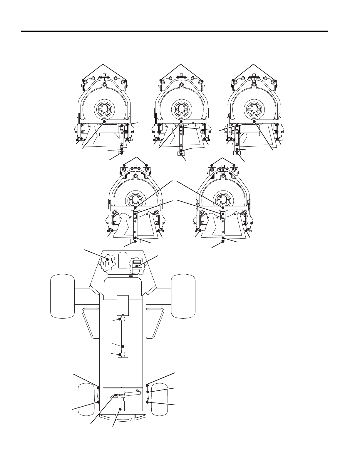
6 TABELLE DELLA MANUTENZIONE E LUBRIFICAZIONE
444
5
11
Raccordi di ingrassaggio
F1 - 50 ore (ogni settimana)
1 Punto di articolazione del tosaerba
(5)
2 Punto di articolazione del braccio di
sollevamento (5)
3 Cilindri di sollevamento (10)
4 Punto di articolazione orientabile e
ruote orientabili (10)
5 Rullo posteriore del tosaerba (10)
6 Punto di articolazione dell'assale
7 Punto di articolazione del pedale di
trazione
8 Giunto sferico (2)
9 Punto di articolazione dello sterzo
(2)
10 Cilindro dello sterzo (2)
F2 - 100 ore
Albero di trasmissione cardanico (3)
6.3 TABELLA DELLA LUBRIFICAZIONE __________________________________________
3
3
5
11
3
2
5
555
3
4
2
1
3
6
2
3
555
7
12
12
12
8
8
10
9
9
10
4
3
1
2
5
3
2
it-32
Page 89

MANUTENZIONE 7
!
7 MANUTENZIONE
7.1 DATI GENERALI ___________________________________________________________
a. Mantenere l'attrezzatura pulita.
AVVERTENZA
Prima di pulire, regolare o riparare questa
apparecchiatura, disinnestare tutti i comandi, abbassare
gli attrezzi a terra, innestare il freno di stazionamento,
arrestare il motore e rimuovere la chiave dall’interruttore
d’accensione per evitare lesioni.
Accertarsi che il tosaerba sia parcheggiato sopra una
superficie solida e livellata. Non effettuare mai dei lavori
su un tosaerba sostenuto soltanto dal cricco di
sollevamento. Usare sempre puntelli a cricco.
1. La regolazione e la manutenzione devono essere
effettuate in tutti i casi da un tecnico qualificato. Se non
è possibile apportare le corrette modifiche, contattare
un Concessionario Jacobsen.
2. Ispezionare periodicamente l'attrezzatura, secondo un
programma di manutenzione, di cui mantenere una
registrazione dettagliata.
b. Mantenere adeguatamente pulite e lubrificate tutte
le parti in movimento.
c. Sostituire le parti usurate o danneggiate prima di
mettere la macchina in movimento.
d. Mantenere tutti i fluidi al livello corretto.
e. Non rimuovere le protezioni e collegare saldamente
i vari componenti alla macchina.
f. Mantenere i pneumatici alla giusta pressione di
gonfiaggio.
3. Quando si effettuano regolazioni o riparazioni, non
indossare gioielli e non slacciare i propri indumenti.
4. Utilizzare le figure del Catalogo Ricambi come
riferimento per smontare e rimontare i componenti.
5. Riciclare o disfarsi di tutti i materiali pericolosi (batterie,
carburanti, lubrificanti, antigelo, ecc.) rispettando le
norme in vigore.
7.2 MOTORE ________________________________________________________________
IMPORTANTE: Un manuale separato del motore,
preparato dal fabbricante del motore, viene fornito con
questo tosaerba. Leggere attentamente il manuale del
motore per familiarizzarsi con il funzionamento e la
manutenzione del motore. Il corretto rispetto delle
istruzioni del fabbricante del motore garantirà la
massima durata in servizio del motore. Per ordinare
manuali del motore sostitutivi contattare il fabbricante
del motore.
Il corretto rodaggio di un nuovo motore ne può cambiare in
modo considerevole la prestazione e la durata.
Durante il periodo di rodaggio, la Jacobsen raccomanda di
attenersi alle seguenti norme:
1. Durante le prime 50 ore di funzionamento, consentire
ad un nuovo motore di raggiungere una temperatura
d’esercizio di almeno 60°C prima del funzionamento a
pieno carico.
2. Controllare il livello dell’olio del motore due volte al
giorno durante le prime 50 ore di funzionamento. Il
consumo dell’olio superiore al normale non è insolito
durante il periodo iniziale di rodaggio.
3. Cambiare l’olio del motore e l’elemento filtrante dell’olio
dopo le prime 50 ore di funzionamento.
4. Controllare e regolare il ventilatore e le cinghie
dell’alternatore.
5. Vedere gli intervalli specifici della manutenzione nella
Sezione 6.2 e nel Manuale del Motore.
Se la pompa ad iniezione, gli iniettori o il sistema del
carburante richiedono la manutenzione, rivolgersi ad un
Concessionario Jacobsen.
AVVISO
Il tosaerba è progettato per funzionare e per tosare nel
modo più efficiente all’impostazione predefinita del
regolatore. Non modificare le impostazioni del regolatore
del motore né accelerare eccessivamente il motore.
7.3 OLIO DEL MOTORE ________________________________________________________
Controllare l’olio del motore all’inizio di ciascuna giornata,
prima di mettere in moto il motore. Se il livello dell’olio è
basso, rimuovere il tappo del serbatoio dell’olio e
rabboccare con olio secondo le esigenze.
Effettuare il cambio dell’olio iniziale dopo le prime 50 ore di
funzionamento e successivamente dopo ogni 100 ore.
Vedere il Manuale del Motore.
Utilizzare soltanto oli per motore con classificazione API CD/
CE.
Sopra 25°C SAE 30W oppure SAE 10W30/10W40
0 - 25°C SAE 20W oppure SAE 10W30/10W40
Sotto 0°C SAE 10W oppure SAE 10W30/10W40
it-33
Page 90
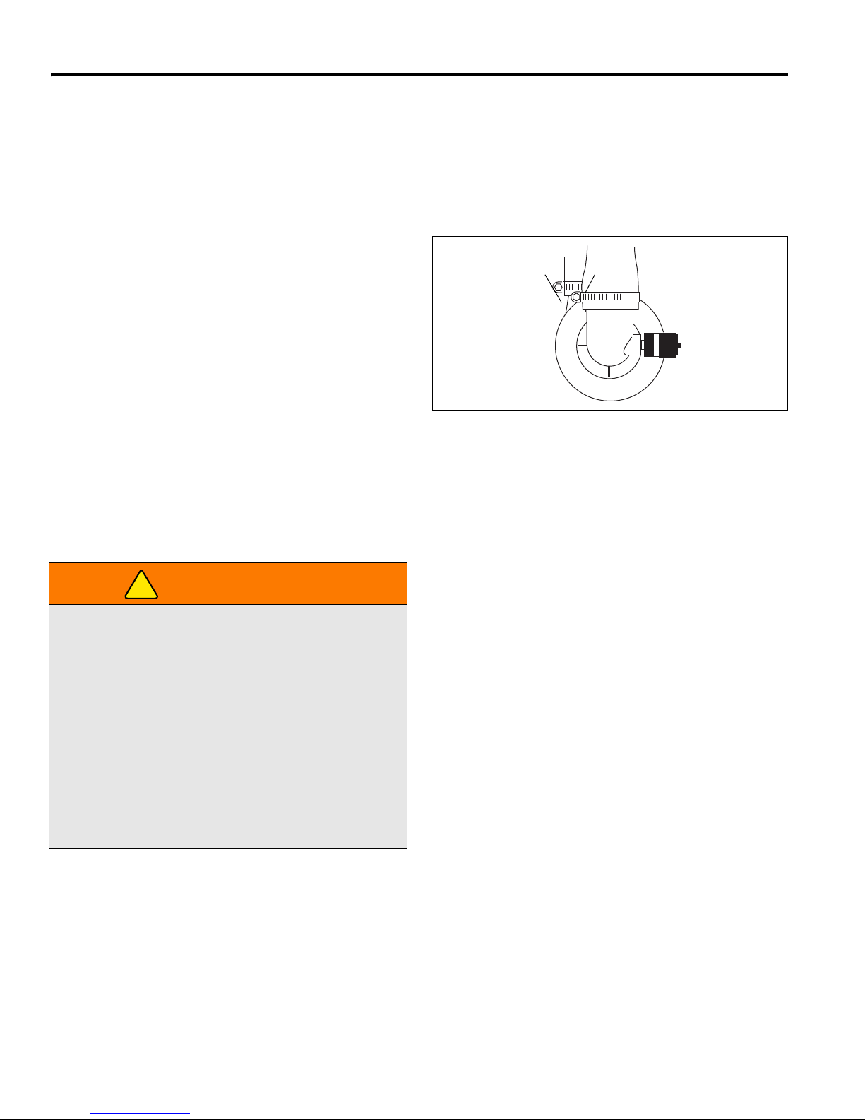
7 MANUTENZIONE
LF017
A
B
!
7.4 FILTRO DELL’ARIA ________________________________________________________
Controllare l’indicatore della manutenzione. Se nella finestra
(B) comprare la banda rossa, sostituire l’elemento.
Non rimuovere l’elemento per controllarlo o pulirlo. La
rimozione non necessaria del filtro aumenta il rischio di
iniettare polvere e altre impurezze nel motore.
Quando la manutenzione è richiesta, pulire prima l’esterno
della sede del filtro; rimuovere quindi il vecchio elemento nel
modo più delicato possibile e gettarlo via.
1. Pulire attentamente l’interno della sede del filtro in
modo tale che la polvere non entri nella presa dell’aria.
2. Esaminare il nuovo elemento. Non usare un elemento
danneggiato e non usare mai un elemento errato.
3. Montare il elemento e accertarsi che sia correttamente
posizionato. Riarmare l’indicatore premendo (A).
4. Rimontare il tappo in modo tale che sigilli totalmente
tutta lasede del filtro. L’evacuatore della polvere deve
essere rivolto verso il basso.
5. Esaminare tutti i tubi flessibili e i condotti dell’aria.
Serrare i fermi dei tubi flessibili.
Figura 7A
7.5 CARBURANTE ____________________________________________________________
Manipolare il carburante con attenzione perché è
infiammabile. Usare un contenitore autorizzato provvisto di
becco inseribile all’interno del bocchettone del serbatoio.
Non usare lattine né imbuti per trasferire il carburante.
AVVERTENZA
Non rimuovere mai il tappo del carburante dal serbatoio
né aggiungere carburante, quando il motore è in funzione
o mentre il motore è caldo.
Non fumare quando si maneggia il carburante. Non
riempire né svuotare il serbatoio in locali chiusi.
• Riempire il serbatoio del carburante fino a 25 mm dal
fondo del bocchettone.
• Usare carburante #2 Diesel, pulito e nuovo. Minimo
Cetane classificazione 45. Vedere ulteriori informazioni
nel Manuale del motore.
• Controllare le linee del carburante e i fermi ogni 50 ore.
Sostituire le linee del carburante e i fermi ai primi segni di
danno.
• Conservare il carburante in conformità a ordinanze locali,
statali o federali e alle raccomandazioni del fornitore di
carburante.
Non riempire mai eccessivamente né lasciare che il
serbatoio si svuoti.
Non manipolare né conservare contenitori di carburante
vicino a fiamme vive o dispositivo che possa produrre
scintille e accendere il carburante o vapori di carburante.
Accertarsi di rimettere in posizione e di chiudere bene il
tappo del serbatoio del carburante.
7.6 SISTEMA DEL CARBURANTE _______________________________________________
Vedere gli intervalli della manutenzione nella Sezione 6.2.
Prima di sostituire qualsiasi filtro, pulire completamente la
sede del filtro e l’area attorno al filtro. Non consentire
l’ingresso di sporco nel sistema del carburante.
Spurgate l’impianto di alimentazione dopo aver rimosso il
filtro e i condotti carburante o dopo aver vuotato il serbatoio
del carburante. Vedere il Manuale del Motore.
it-34
• Non riempire mai eccessivamente né consentire mai che
il serbatoio si svuoti.
Sostituzione del filtro del carburante:
1. Chiudere il rubinetto del carburante sul serbatoio; quindi
rimuovere e gettare il filtro esistente.
2. Applicare un velo d’olio sulla guarnizione e stringere il
nuovo filtro senza forzare.
3. Riempire il serbatoio del carburante. Aprire la valvola e
spurgare il filtro. Consultare il Manuale del Motore.
Page 91
MANUTENZIONE 7
!
!
!
!
7.7 BATTERIA________________________________________________________________
Accertarsi che l’interruttore d’accensione sia effettivamente
spento e che la chiave sia stata rimossa prima di effettuare
la manutenzione sulla batteria.
ATTENZIONE
Usare sempre utensili isolati, indossare occhiali protettivi
o di sicurezza e indumenti protettivi quando si effettuano
dei lavori sulle batterie. Leggere e attenersi a tutte le
istruzioni del fabbricante della batteria.
Serrare bene i cavi ai morsetti della batteria e applicare un
leggero strato di grasso dielettrico siliconico ai morsetti e
alle estremità dei cavi per prevenire la corrosione. Tenere i
coperchi di ventilazione e i coperchi dei morsetti in
posizione.
Esaminare il livello dell’elettrolito ogni 100 ore. Tenere pulite
le estremità dei cavi, la batteria e i montanti della batteria.
Verificare la polarità della batteria prima di collegare o
scollegare i cavi della batteria.
1. Quando si installa la batteria, montare sempre il cavo
ROSSO positivo (+) della batteria per primo e il cavo
NERO negativo (-) di massa per ultimo.
2. Quando si rimuove la batteria, rimuovere sempre il
cavo NERO negativo (-) di massa per primo e il cavo
ROSSO positivo (+) per ultimo.
3. Accertarsi che la batteria sia correttamente installata e
fissata al vassoio della batteria.
AVVERTENZA
Poli, morsetti ed accessori della batteria contengono
piombo e composti, elementi chimici che secondo lo
Stato della California possono causare cancro e danni
alla riproduzione. Lavate le mani dopo averli toccati.
7.8 MESSA IN MOTO CON IL COLLEGAMENTO DI DUE BATTERIE ____________________
Prima di tentare mettere in moto il tosaerba con il
collegamento di due batterie, controllare le condizioni della
batteria scarica. Sezione 4.7.
AVVERTENZA
Le batterie generano gas idrogeno esplosivo. Per ridurre
la possibilità di un’esplosione evitare la creazione di
scintille nelle vicinanze della batteria. Connettere sempre
il cavo negativo di collegamento per la messa in moto al
telaio del tosaerba con la batteria scarica.
Quando si collegano i cavi di collegamento per la
messa in moto:
1. Arrestare il motore sul veicolo con la batteria in buone
condizioni.
2. Connettere il cavo di collegamento per la messa in
moto ROSSO al morsetto positivo (+) sulla batteria in
buone condizioni e al morsetto positivo (+) sulla
batteria scarica.
3. Connettere il cavo di collegamento per la messa in
moto NERO dal morsetto negativo (-) sulla batteria in
buone condizioni al telaio del tosaerba con la batteria
scarica.
7.9 CARICAMENTO DELLA BATTERIA __________________________________________
AVVERTENZA
Caricare la batteria in un’area ben ventilata. Le batterie
generano gas esplosivi. Per prevenire un’esplosione,
tenere le fiamme lontano dalla batteria.
Per prevenire lesioni, stare lontani dalla batteria quando
il caricatore è acceso. Una batteria danneggiata
potrebbe esplodere.
Dopo aver connesso i cavi, mettere in moto il motore sul
veicolo con la batteria in buone condizioni e mettere in moto
quindi il tosaerba.
1. Vedere la Sezione 4.7. Leggere le istruzioni specifiche
nel manuale della batteria e del caricatore.
2. Se possibile, rimuovere la batteria dal tosaerba prima
di caricarla. Se la batteria non è sigillata, controllare
che l’elettrolito copra le piastre in tutte le celle.
3. Accertarsi che il caricatore sia spento. Connettere
quindi il caricatore ai morsetti della batteria nel modo
specificato nel manuale del caricatore.
4. Spegnere sempre il caricatore prima di disconnettere il
caricatore dai morsetti della batteria.
it-35
Page 92

7 MANUTENZIONE
!
!
7.10 SILENZIATORE E TUBO DI SCARICO _________________________________________
Serrare tutti i componenti del collettore di scarico ad una
coppia uniforme. Serrare o sostituire i fermi dello scarico.
AVVERTENZA
I fumi di scarico contengono ossido di carbonio che è
tossico e può essere letale se inalato.
NON azionare MAI un motore senza la corretta
ventilazione.
7.11 TUBI IDRAULICI FLESSIBILI ________________________________________________
AVVERTENZA
Per prevenire gravi lesioni causati dall’olio caldo ad alta
pressione, non verificare mai la presenza di perdite d’olio
con le mani, ma usare carta o cartone.
Il liquido idraulico in uscita sotto pressione può essere
forte da penetrare nella pelle. Se il liquido viene iniettato
nella pelle deve essere chirurgicamente rimosso entro
alcune ore da un medico esperto nel trattamento di
questo tipo di lesione, per evitare la possibile.
1. Prima di esaminare o scollegare le linee o i tubi idraulici
flessibili abbassare gli attrezzi a terra, disconnettere tutti
i comandi, innestare il freno di stazionamento, arrestare
il motore e rimuovere la chiave.
2. Controllare i tubi flessibili e i tubi rigidi visibili
quotidianamente. Verificare la presenza di tubi bagnati
o di macchie d’olio. Sostituire tubi flessibili e tubi rigidi
logori o danneggiati prima di azionare la macchina.
3. I tubi rigidi o flessibili devono essere disposti nello
stesso percorso dei tubi esistenti; non spostare fermi,
supporti e tiranti ad una nuova posizione.
4. Esaminare completamente tutti i tubi rigidi, i tubi
flessibili e i raccordi ogni 250 ore.
Per proteggere dall’avvelenamento dell’ossido di carbonio,
esaminare regolarmente tutto il sistema di scarico e
sostituire sempre un silenziatore difettoso.
Se si nota un cambiamento del colore o del suono dello
scarico, arrestare immediatamente il motore. Identificare il
problema e far riparare il sistema.
IMPORTANTE: Il sistema idraulico può essere
permanentemente danneggiato se l’olio diventa
contaminato. Prima di disconnettere qualsiasi
componente idraulico, pulire l’area attorno ai fissaggi e
alle estremità dei tubi flessibili per impedire l’ingresso di
impurezze nel sistema.
a. Prima di disconnettere qualsiasi componente
idraulico, contrassegnare la posizione di tubo
flessibile e pulire quindi l’area attorno ai fissaggi.
b. Mentre si scollega il componente, essere pronti a
montare i tappi o i coperchi alle estremità dei tubi
flessibili e alle porte aperte. In questo modo si
impedisce l’ingresso delle impurezze nel sistema
idraulico e si prevengono le dispersioni d’olio.
c. Accertarsi che gli O-ring siano puliti e che i fissaggi
dei tubi flessibili siano posizionati prima di serrare.
d. Impedire che il tubo flessibile si avvolga. I tubi
avvolti possono causare l’allentamento degli
accoppiatori perché il tubo flessibile si flette durante
il funzionamento, con conseguenti perdite d’olio.
e. I tubi piegati o avvolti possono limitare il flusso
dell’olio con conseguente malfunzionamento del
sistema e surriscaldamento dell’olio e possono
anche causare il guasto dei tubi flessibili.
7.12 OLIO IDRAULICO__________________________________________________________
Vedere gli intervalli della manutenzione nella Sezione 6.2.
Spurgare e sostituire l’olio idraulico dopo un guasto del
componente o se si nota la presenza d’acqua o schiuma
nell’olio o un odore rancido (indica calore eccessivo).
Sostituire sempre il filtro idraulico quando si cambia l’olio.
Cambio dell’olio idraulico
1. Pulire l’area attorno al tappo dell’olio per prevenire
l’ingresso di impurezze e contaminazione del sistema.
2. Rimuovere il tappo di scarico dal fondo del serbatoio.
3. Dopo aver drenato l’olio installare il tappo di scarico e
riempire con olio idraulico Jacobsen.
it-36
4. Spurgare l’aria dal sistema.
a. Per evitare il surriscaldamento delle bobine, stac-
care il motore dalle bobine.
b. Far funzionare tutti i dispositivi del tosaerba per 5
minuti, per rimuovere l'aria e stabilizzare il livello
dell'olio. In questa fase, è possibile che suoni
l'allarme del livello dell'olio.
c. Una volta stabilizzato il livello e aver tolto l'aria,
riempire il serbatoio dell'olio fino alla tacca di pieno
sull'astina. Avviare il motore e controllare che il
segnale acustico di mancanza di olio non si attivi.
Page 93
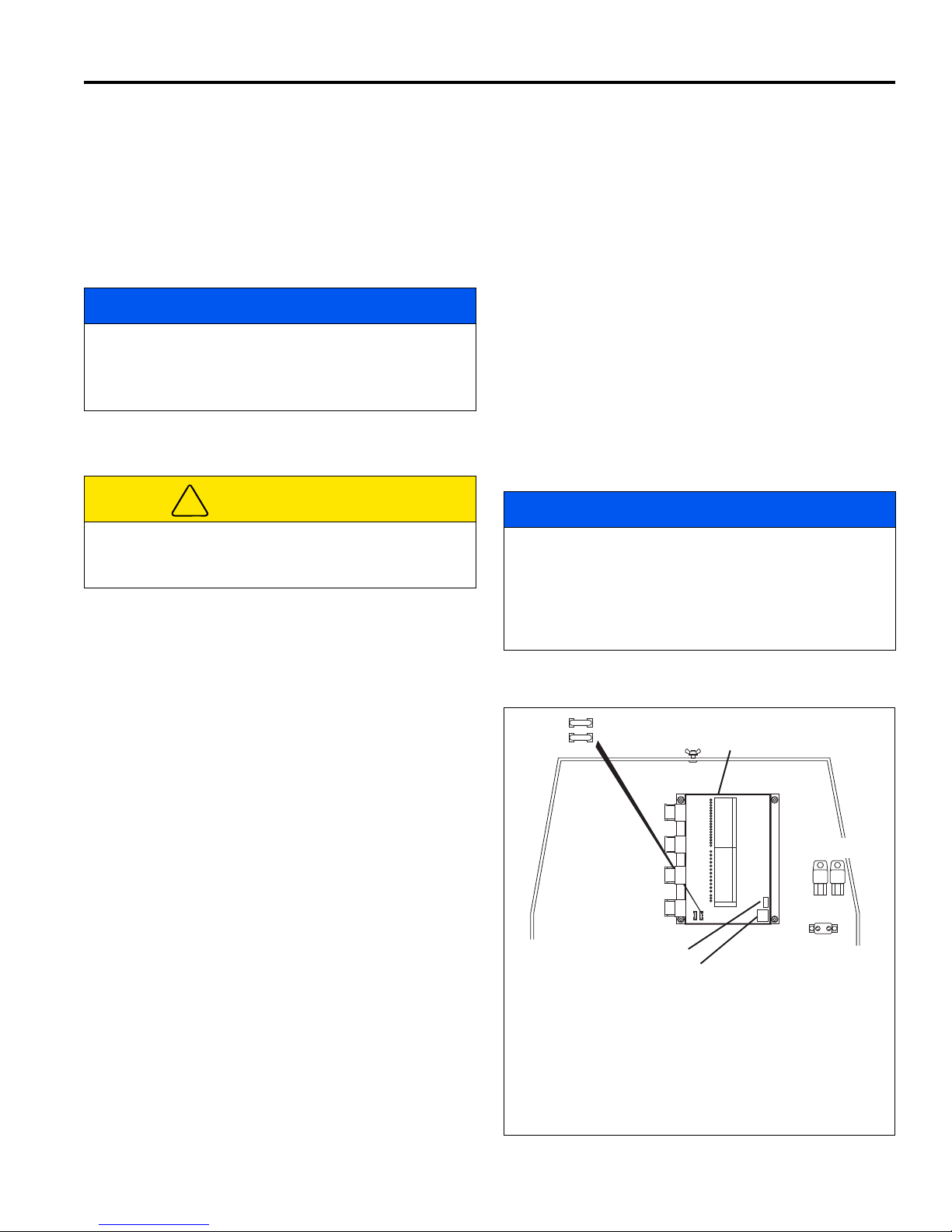
MANUTENZIONE 7
!
TAGLIACIRCUITO
CB1 50 A TAGLIACIRCUITO
FUSIBILI
F1 20 A ALTERNATORE, STRUMENTI DI MISURA
F2 20 A FARI
RELÈ
K1 CANDELA A INCANDESCENZA
K2 MOTORINO DI AVVIAMENTO
7.13 FILTRI DELL’IMPIANTO IDRAULICO __________________________________________
L’impianto idraulico è protetto da due filtri da 10 micron: il
filtro sulla linea di ritorno. Durante il funzionamento viene
controllato il flusso attraverso i filtri e quando la caduta di
pressione tra i filtri è eccessiva si accende la spia del filtro
olio dell’impianto idraulico. Per garantire protezione
continua all’impianto idraulico, sostituire entrambi i filtri al
più presto, dopo l'accensione della spia.
AVVISO
Nella stagione fredda, è possibile che la spia si accenda
fin quando l'olio non raggiunge la temperatura di
esercizio. Attendere che l'olio si sia scaldato e la spia si
sia spenta, prima di mettere in funzione il tosaerba.
Sostituzione dei filtri dell’impianto idraulico:
1. Togliere i vecchi filtri.
2. Installare i nuovi filtri, stringendoli soltanto a mano.
3. Far funzionare il motore al minimo per cinque minuti
tenendo l’impianto idraulico in folle. In questa fase
potrà suonare l'allarme del livello dell’olio.
Controllare il livello dell’olio nel serbatoio dell’impianto
idraulico e riempire fino alla tacca di pieno sull'astina.
7.14 SISTEMA ELETTRICO ______________________________________________________
ATTENZIONE
Spegnere sempre l’interruttore d’accensione e rimuovere
il cavo (NERO) negativo della batteria prima di
controllare o di effettuare dei lavori sul sistema elettrico.
Le precauzioni generali che possono essere adottate per
ridurre i problemi elettrici sono elencate di seguito.
1. Accertarsi che tutti i morsetti e i raccordi siano puliti e
correttamente fissati.
2. Esaminare regolarmente il sistema microinterruttore di
sicurezza e gli interruttori automatici.
Se il sistema microinterruttore di sicurezza non
funziona correttamente e il problema non può essere
rettificato, rivolgersi ad un concessionario Jacobsen.
Se richiedete assistenza dalla fabbrica per localizzare
eventuali guasti del controller, prendete nota della
revisione dell’hardware del controller e della versione del
software, riportate sull’angolo destro inferiore del
controller. I controller aventi livelli di revisione pari o
superiori sono compatibili con le versioni precedenti.
I circuiti sono protetti da un interruttore di sicurezza, da
fusibili e da relè montati vicino alla centralina.
F1
F2
AVVISO
C
3. Per prevenire danni, tenere il cablaggio dei fili e tutti i
singoli fili lontano da parti moventi.
4. Accertarsi che il cablaggio dell’interruttore del sedile
sia connesso al cablaggio dei fili principale.
5. Controllare la batteria e il circuito di caricamento della
batteria.
6. Non lavare né pulire con nebulizzatori a pressione
attorno ai raccordi e ai componenti elettrici.
L'impianto elettrico è controllato e gestito dalla centralina
elettronica (C) collocata dietro la zona dell'operatore. La
centralina è dotata di quattro serie di LED che servono per
analizzare i guasti dell'impianto elettrico; vedere la Sezione
5.2.
Versione Software
Revisione Hardware
K2
K1
CB1
Figura 7B
it-37
Page 94
7 MANUTENZIONE
!
!
!
!
7.15 RADIATORE ______________________________________________________________
Miscelare acqua pulita con antigelo a base di glicole
AVVERTENZA
Per prevenire gravi lesioni al corpo causate dal
refrigerante caldo o da uno scoppio del vapore, non
tentare mai di rimuovere il tappo del radiatore mentre il
motore è in funzione. Arrestare il motore e attendere
finché si è raffreddato. Anche quando è freddo,
rimuovere il tappo con estrema attenzione.
etilenico più adatto per le basse temperature. Attenersi alle
istruzioni sulla confezione dell'antigelo e sul manuale del
motore.
Mantenere puliti i condotti dell’aria del radiatore e dello
scambiatore di calore dell'olio dell’impianto idraulico. Pulire
le alette di raffreddamento con aria compressa (massimo
210 kPa).
Pulizia del radiatore:
ATTENZIONE
Non versare acqua fredda in un radiatore caldo. Non
azionare il motore senza una corretta miscela
refrigerante. Installare il tappo e serrare bene.
Controllare quotidianamente il livello del refrigerante. Il
radiatore dev'essere pieno e la bottiglia di recupero
dev'essere al livello indicato con freddo.
Svuotare e riempire una volta l'anno. Togliere il tappo del
radiatore, aprire lo scarico sul blocco motore e lo scarico sul
radiatore. Svuotare e pulire la bottiglia di recupero.
1. Pulire le alette del radiatore e dello scambiatore di
calore con una pistola ad aria compressa.
AVVISO
Per far cadere sporcizia e detriti a terra attraverso il
telaio si può allentare e spingere all'indietro il pannello
scorrevole posto sotto il telaio.
2. Controllare e mettere in tensione la cinghia del
ventilatore. Sostituire morsetti e raccordi ogni due anni.
3. Se ci si trova a dover rabboccare il serbatoio del
refrigerante più di una volta al mese o ad aggiungerne
più di un litro per volta, far controllare l’impianto di
raffreddamento da un rappresentante Jacobsen.
7.16 GABBIA ANTIRIBALTAMENTO (ROPS) ________________________________________
Tra gli accessori, è disponibile una gabbia antiribaltamento
(ROPS) progettata appositamente per questo tosaerba. Se
il tosaerba la monta, ispezionarla periodicamente e seguire
le procedure descritte nel Manuale per l’uso e la
sicurezza.
ATTENZIONE
Non allentare o rimuovere i bulloni; non saldare,
trapanare, modificare, piegare o raddrizzare una
struttura danneggiata.
1. Il sedile, la cintura di sicurezza, gli attrezzi per il
montaggio e qualsiasi altro accessorio del ROPS
debbono essere ispezionati regolarmente e tutte le parti
danneggiate essere immediatamente sostituite.
2. Se il ROPS subisce un qualunque tipo di impatto,
sostituirlo immediatamente.
3. Controllare e rimettere in torsione tutta l’attrezzeria. I
pezzi di ricambio per il ROPS devono essere solo
quelli indicati nel Catalogo dei Ricambi.
7.17 PNEUMATICI _____________________________________________________________
1. Tenere i pneumatici correttamente gonfi per prolungarne la durata. Controllare la pressione di gonfiaggio
mentre i pneumatici sono freddi. Controllare il bat
tistrada.
2. Controllare la pressione ogni 50 ore oppure una volta
al mese. Utilizzare un manometro di precisione per
pneumatici a basse pressioni.
3. Mantenere i pneumatici alla pressione di gonfiaggio di:
Anteriori - 111 kPa
it-38
Posteriori - 86 kPa
-
ATTENZIONE
Se non si dispone dell’addestramento, degli utensili e
dell’esperienza corretti, NON tentare di montare un
pneumatico ad un cerchione. Il montaggio incorretto può
produrre un’esplosione che può causare gravi lesioni.
Page 95
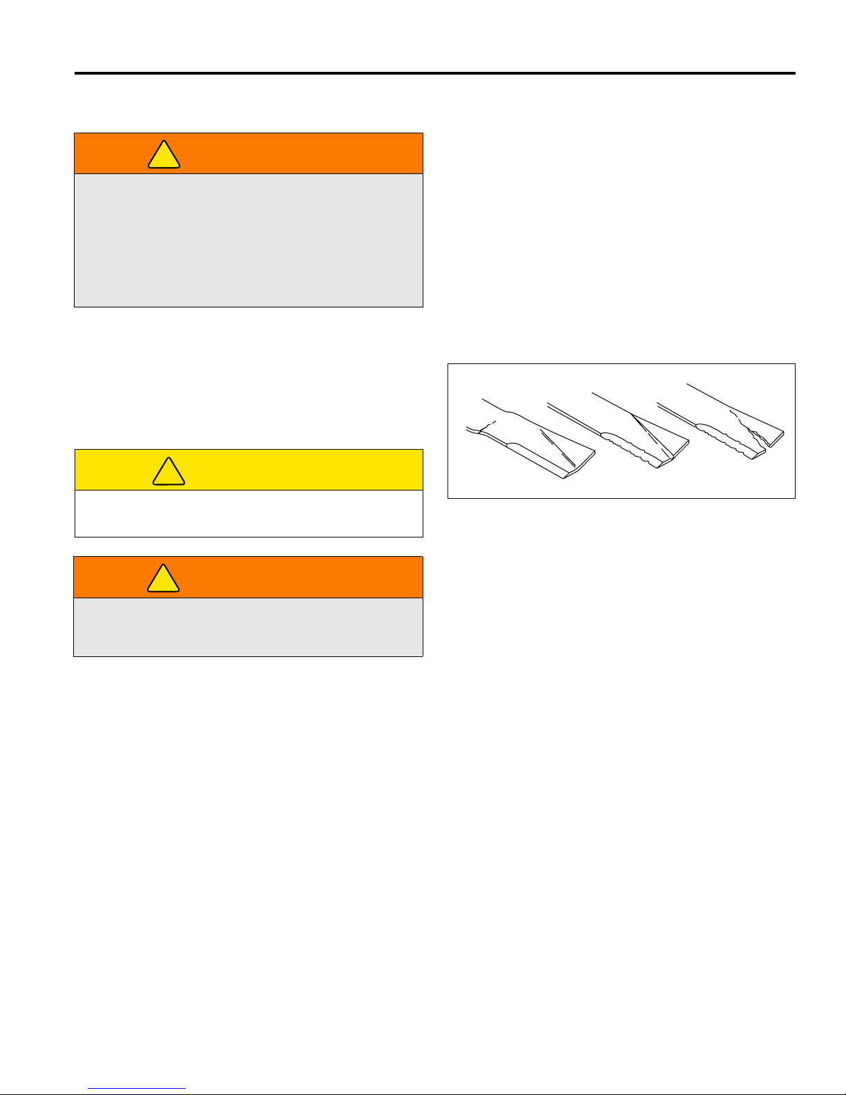
MANUTENZIONE 7
!
!
!
G
H
J
HR025
7.18 PROCEDIMENTO DI MONTAGGIO DELLE RUOTE _______________________________
1. Rimuovere lo sporco, il grasso e l’olio dalla filettatura
AVVERTENZA
Accertarsi che il tosaerba sia parcheggiato sopra una
superficie solida e livellata. Non effettuare mai dei lavori
su un tosaerba sostenuto soltanto dal cricco di
sollevamento. Usare sempre puntelli a cricco.
Se soltanto la parte anteriore o posteriore del tosaerba è
sollevata, mettere dei tacchi davanti e dietro le ruote che
non sono sollevate
7.19 ISPEZIONE DELLE LAME ___________________________________________________
1. Controllate accuratamente le lame ogni 50 ore di
servizio, od ogni volta che il tosaerba viene tolto dal
tosaerba, per accertare che siano in buone condizioni di
servizio. Sostituite le lame curve (G), scanalate (H) o
incrinate (J)
.
del perno prigioniero. Non lubrificare le filettature.
2. Posizionare la ruota sul mozzo e controllarla per
verificare il contatto totale fra la superficie di montaggio
della ruota e il mozzo o il tamburo del freno.
3. Serrare con le dita tutti i componenti e poi serrare a
coppia i componenti in ordine incrociato. Serrare
sempre i dadi nella posizione superiore.
4. Controllare e risserrare giornalmente finché la coppia
viene mantenuta, 115-128 Nm.
ATTENZIONE
Prestate attenzione quando controllate le lame, per
non pizzicare mani o dita tra le estremità delle lame.
AVVERTENZA
Non cercate di raddrizzare, saldare o riparare le lame
danneggiate. Le lame danneggiate devono essere
sempre sostituite.
2. Una qualsiasi delle succitate avarie può causare la
rottura di una scheggia di lama, che verrebbe lanciata
dal motore causando gravi ferite agli astanti o altri
danni.
3. Le lame curve possono avere incrinature
microscopiche (G) che si allargano e causano la
rottura di un pezzo di lama. Le lame curve causano
anche vibrazioni ed altre sollecitazioni della macchina.
4. La polvere e i granelli di sabbia possono creare gravi
scanalature sulla lama (H) tra le alette dell’aria e la
sezione piatta della lama, che si allargano rapidamente
e producono un’incrinatura (J) che causa la rottura
dell’aletta
.
Figura 7C
it-39
Page 96
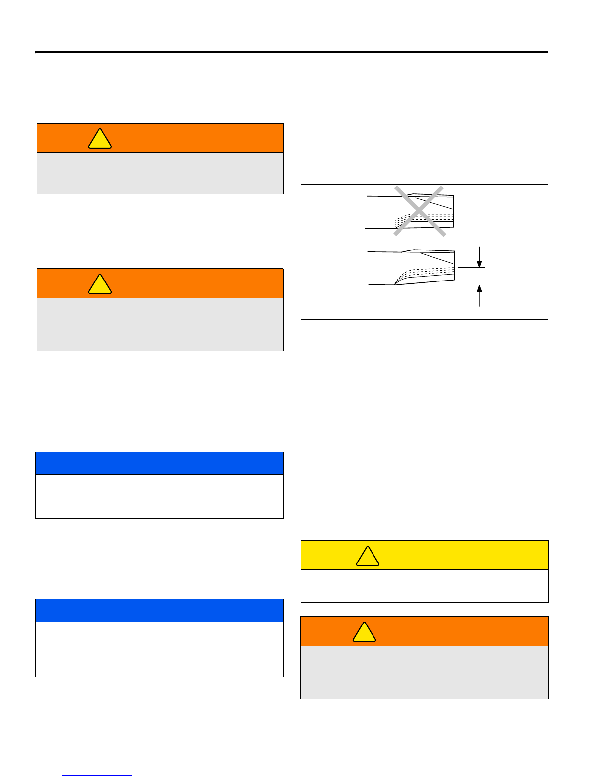
7 MANUTENZIONE
!
!
A
B
13 mm
Massimo
HR024
!
!
7.20 AFFILATURA DELLE LAME _________________________________________________
1. Inserite un blocco di legno tra la lama e la scocca del
tosaerba, per impedire il movimento della lama.
AVVERTENZA
Le lame del tosaerba possono avere bordi taglienti.
Maneggiatele con cautela durante la revisione e
l’ispezione.
2. Durante l’affilatura della lama non seguite l’affilatura
originale illustrata in (A). Affilate il bordo tagliente
all’angolo indicato in (B).
Se la perdita massima totale della lama è di 13 mm, non
continuate ad affilare ma sostituite la lama.
AVVERTENZA
L’affilatura della lama oltre i 13 mm ammissibili favorisce
la rottura della punta della lama, che può essere lanciata
dal tosaerba. Un incidente di questo genere può
causare gravi infortuni agli astanti e/o altri danni.
3. Per non sbilanciare la lama dovete togliere un’identica
quantità di materiale da entrambi i lati della lama. Una
lama sbilanciata causa vibrazioni eccessive e può
danneggiare il tosaerba.
4. In seguito all’affilatura controllate la lama con un
bilanciatore per lame.
5. Serrate la vite di montaggio centrale della lama a un
valore compreso tra 100 e 120 Nm.
Figura 7D
7.21 CURA E PULIZIA __________________________________________________________
Lavare il tosaerba e gli attrezzi dopo ciascun uso. Tenere le
apparecchiature pulite.
AVVISO
Non lavare qualsiasi parte dell’apparecchiatura mentre è
calda. Non usare spruzzi o vapore ad alta pressione.
Usare acqua fredda e detergenti per automobili.
1. Usare aria compressa per pulire il motore e le alette del
radiatore. Una pistola speciale è disponibile presso i
concessionari Jacobsen.
2. Usate soltanto acqua dolce per la pulizia delle vostre
apparecchiature.
4. Pulire tutte le rifiniture di plastica o di gomma con una
soluzione di sapone delicato o usare detergenti per
vinile/gomma disponibili in commercio.
5. Per mantenere la brillantezza originale della
vetroresina, lucidatela periodicamente con cera
detergente one-step di buona qualità.
Riparare le superfici metalliche danneggiate e usare vernice
di ritocco Jacobsen. Per ottenere la massima protezione
della vernice lucidare l’apparecchiatura con cerai.
ATTENZIONE
Pulire l’erba e i detriti dalle unità di taglio, i comandi, i
silenziatori e il motore per prevenire gli incendi
.
AVVISO
L'uso di acqua salata o di un affluente può favorire la
ruggine e la corrosione delle parti metalliche, ed
anticiparne il deterioramento o l’avaria. La garanzia della
fabbrica non copre danni di questo tipo.
3. Non spruzzare l’acqua direttamente sul quadro degli
strumenti, l’interruttore d’accensione, il controllore o
qualsiasi altro componente elettrico o sulle sedi dei
cuscinetti e sui dispositivi di tenuta.
it-40
NON usare MAI le mani per pulire le unità di taglio.
Usare una spazzola per rimuovere l’erba tagliata dalle
lame. Le lame sono estremamente affilate e possono
causare gravi lesioni.
AVVERTENZA
Page 97
MANUTENZIONE 7
!
!
7.22 CONSERVAZIONE _________________________________________________________
Dati generali
1. Lavare bene e lubrificare il tosaerba. Riparare e
verniciare il metallo danneggiato o esposto.
2. Esaminare il tosaerba, serrare tutti i componenti,
sostituire i componenti logori o danneggiati.
3. Svuotare e riempire nuovamente il radiatore.
4. Pulire i pneumatici bene e conservare il tosaerba così
che il carico non sia disposto sui pneumatici. Se il
tosaerba non si trova su puntelli a cricco, esaminare
regolarmente i pneumatici e rigonfiarli secondo le
esigenze.
5. Tenere la macchina e tutti i suoi accessori puliti,
asciutti e protetti dagli elementi durante la
conservazione. Non conservare mai le apparecchiature
vicino ad una fiamma aperta o una scintilla che
potrebbe accendere il carburante o i vapori del
carburante.
Batteria
1. Rimuovere, pulire e conservare la batteria in posizione
verticale su una superficie non conduttiva in un luogo
fresco e asciutto. Per evitare un scarico accelerato, non
mantenere la batteria su superficie di cemento o
d'acciaio.
2. Controllare e ricaricare la batteria ogni 60-90 giorni
durante la conservazione.
3. Conservare le batterie in un luogo fresco e asciutto.
Per ridurre il tasso di autoscaricamento, la temperatura
ambientale non dovrebbe superare 27°C né essere
inferiore a -7°C per prevenire il congelamento
dell’elettrolito.
Unità di taglio
1. Lavare bene le unità di taglio, poi riparare e verniciare
qualsiasi metallo danneggiato o esposto.
2. Lubrificare tutti i fissaggi e i punti di frizione.
3. Applicare un leggero strato di olio antiruggine ai bordi
affilati della bobina e della lama fissa.
ATTENZIONE
Per prevenire lesioni personali e danni ai bordi di taglio,
manipolare la bobina con estrema attenzione.
Dopo la conservazione
1. Controllare e reinstallare la batteria.
2. Controllare o effettuare la manutenzione sul filtro del
carburante e il pulitore dell’aria.
3. Controllare il livello di refrigerante nel radiatore.
4. Controllare il livello dell’olio nella coppa del motore e
nel sistema idraulico.
5. Riempire il serbatoio del carburante con nuovo
carburante. Spurgare il sistema del carburante.
6. Accertarsi che i pneumatici siano correttamente gonfi.
7. Rimuovere tutto l’olio dalle bobine e dalla lama fissa.
Regolare la lama fissa e l’altezza di taglio.
8. Mettere in moto e far funzionare il motore a metà
accelerazione. Consentire tempo sufficiente per
riscaldare e lubrificare correttamente il motore.
Motore
1. Mentre il motore è caldo, rimuovere il tappo di scarico,
spurgare l’olio dalla coppa e cambiare il filtro dell’olio.
Installare il tappo di scarico e riempire con olio fresco.
Applicare sul tappo una coppia di 30 Nm.
2. Pulire l’esterno del motore. Verniciare il metallo
esposto o applicare un leggero strato di olio
antiruggine.
3. Aggiungere un condizionatore del carburante o un
biocida per prevenire la formazione di gel o la crescita
di batteri nel carburante. Consultare il proprio fornitore
di carburante.
AVVERTENZA
Non far mai funzionare il motore senza la corretta
ventilazione; i fumi di scarico possono essere letali se
inalati.
it-41
Page 98
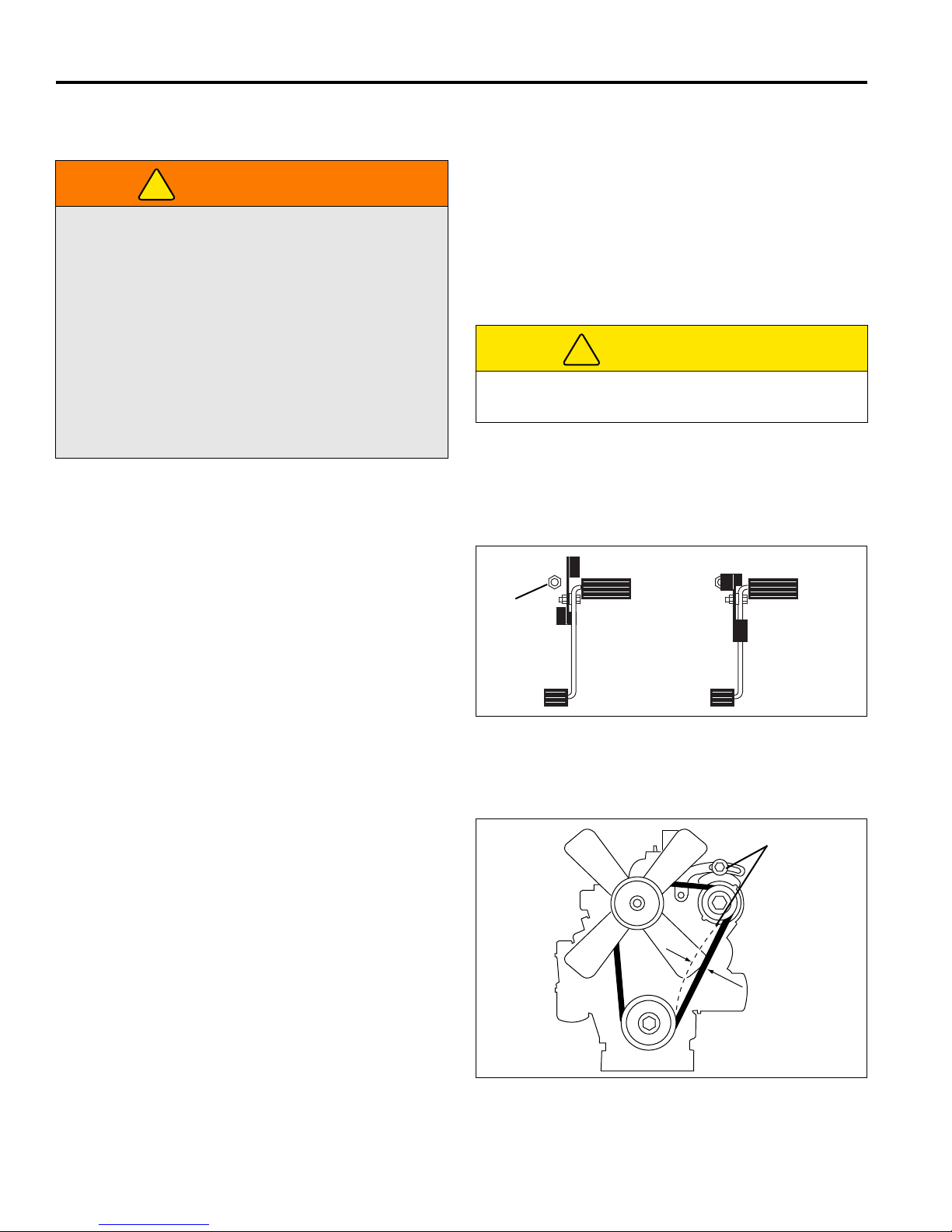
8 REGOLAZIONI
!
!
A
LF002
6 - 8 MM
B
LF012
8 REGOLAZIONI
8.1 DATI GENERALI___________________________________________________________
1. Le regolazioni e la manutenzione devono essere
AVVERTENZA
Per prevenire lesioni, abbassare gli attrezzi a terra,
disinnestare tutti i comandi, innestare il freno di
stazionamento, arrestare il motore e rimuovere la chiave
dall’interruttore d’accensione prima di apportare
qualsiasi modifica o di effettuare la manutenzione.
Accertarsi che il tosaerba sia parcheggiato sopra una
superficie solida e livellata. Non effettuare mai dei lavori
su un tosaerba sostenuto soltanto dal cricco di
sollevamento. Usare sempre puntelli a cricco.
Se soltanto la parte anteriore o posteriore del tosaerba è
sollevata, mettere dei tacchi davanti e dietro le ruote che
non sono sollevate.
8.2 VELOCITÀ DI FALCIATURA _________________________________________________
sempre effettuate da un tecnico qualificato. Se non è
possibile effettuare la corretta regolazione, contattare
un concessionario Jacobsen.
2. Sostituire, non modificare, componenti logori o
danneggiati.
3. I capelli lunghi, i gioielli o gli indumenti larghi possono
impigliarsi nelle parti moventi.
ATTENZIONE
Prestare attenzione per non intrappolare le mani e le dita
fra i componenti moventi e fissi della macchina.
4. Non modificare le impostazioni del regolatore né
accelerare eccessivamente il motore.
La qualità della falciatura è migliore a velocità molto al di
sotto di quella di trasporto del tosaerba. La velocità di
falciatura impostata in fabbrica è di 8-10 km/h e dovrebbe
essere adatta alla maggior parte delle condizioni di
falciatura. Tuttavia, con un particolare tipo di terreno, può
rendersi necessario operare a velocità diversa.
Per impostare la velocità di falciatura, stringere il dado di
fissaggio (A) e regolare la vite di arresto verso l'alto per
ridurre la velocità e verso il basso per aumentarla. Stringere
il dado per mantenere la regolazione in posizione.
Figura 8A
8.3 CINGHIA _________________________________________________________________
Controllare e registrare la cinghia nuova dopo le prime 10
ore di funzionamento. Successivamente ripetere i controlli e
la registrazione ogni 100 ore.
Registrare la puleggia dell’alternatore in modo che la
cinghia si fletta di 6-8 mm esercitando una pressione di ca.
10 kg a metà strada tra le pulegge. Vedere il manuale del
motore
Se la tensione non è quella corretta, allentare i bulloni di
montaggio dell'alternatore (B) e regolare l'alternatore fino a
ottenere la tensione corretta.
it-42
Figura 8B
Page 99
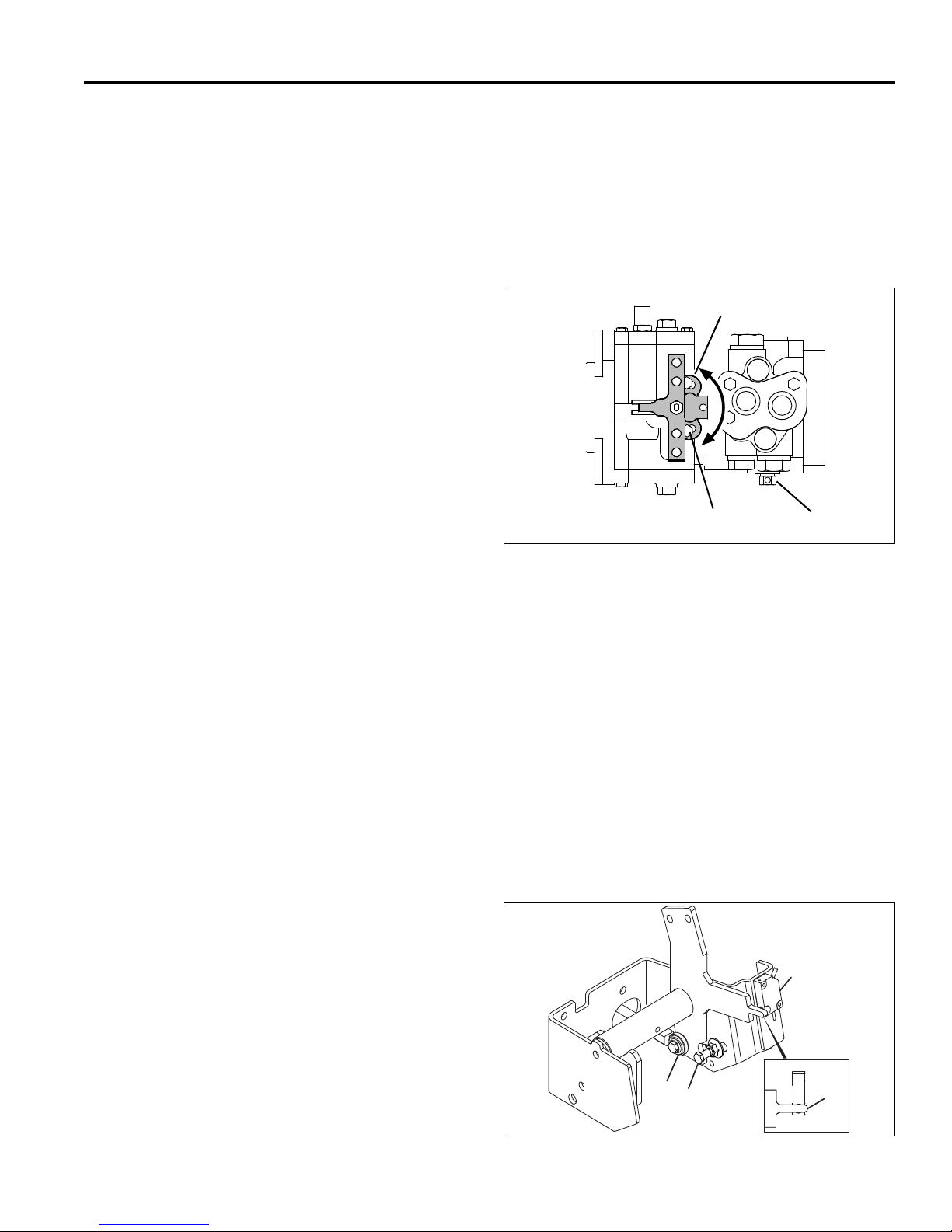
REGOLAZIONI 8
F
H
G
LF014
J
K
L
M
8.4 REGOLAZIONE DEL FOLLE _________________________________________________
La regolazione del folle può esser fatta soltanto sulla pompa
della presa di forza.
La regolazione del folle è preimpostata in fabbrica su tutti i
trattori e le pompe, nuovi o di ricambio. Non sono richieste
ulteriori regolazioni a meno che la pompa non sia stata
smontata per riparazione o manutenzione.
Regolare del folle:
1. Scollegare dalla pompa il collegamento del pedale della
trazione.
2. Collocare il tosaerba su appoggi ben saldi in modo che
tutte le ruote siano sollevate da terra.
3. Controllare che la valvola di rimorchio (H) sia chiusa.
4. Inserire il freno di stazionamento e mettere
l'interruttore di falciatura in folle. Accertarsi che
l'interruttore del folle sul pedale della trazione sia
chiuso. (M-Figura 3E).
puntatore metallico (M) dev’essere tra 1,5 e 3 mm.
5. Allentare le viti (G) che sostengono la staffa della leva
della pompa quanto basta per poterla spostare.
Avviare il motore e osservare le ruote. Regolare la
staffa (F) nei fori a feritoia finché le ruote non girano.
Spegnere il motore e stringere la staffa in posizione.
La distanza tra l’interruttore e il
6. Collegare il giunto della trazione al pedale della
trazione, assicurandosi che l’indicatore sul pedale della
trazione si trovi in corrispondenza dell'interruttore del
folle (M-Figura 3E).
7. Avviare il motore e controllare il funzionamento del
pedale della trazione. Le ruote non devono girare
riportando il pedale in posizione di folle e deve
accendersi la spia 5 sulla centralina, vedi Sezione 9.2.
Figura 8C
8.5 MARCE AVANTI / RETROMARCIA ____________________________________________
Le marce in avanti e la retromarcia sono regolate sul pedale
della trazione. Innestare la marcia avanti prima di regolare la
retromarcia.
Regolazione della marcia in avanti:
1. Accertarsi che la pompa della presa di forza sia stata
messa in folle e la manetta sia regolata correttamente.
2. Avviare il motore e controllare la velocità di
avanzamento con il motore al massimo e il tosaerba su
2 ruote motrici (2WD). La velocità di avanzamento
deve essere di 16 km/h.
3. Spegnere il motore. Per regolare la velocità, togliere il
bullone ad occhione (K) dal pedale e allentare il dado
di fissaggio. Ruotare il bullone ad occhione verso
l'interno per ridurre la velocità e verso l'esterno per
aumentarla. Stringere il dado di fissaggio per
mantenere la regolazione in posizione e rimettere il
bullone ad occhione.
4. Con il pedale della trazione in folle, controllare la
posizione dell'interruttore del folle (J). Regolare
l'interruttore in su o in giù in modo che l’indicatore (M)
sulla staffa del pedale della trazione si trovi al centro di
sopra di esso. Se regolato correttamente, portando
l'interruttore di accensione su avviamento, si
accenderà la spia 5 sulla centralina.
5. Avviare il motore e controllare la velocità. Ripetere la
procedura finché si raggiunge una velocità di
avanzamento di 16 km/h.
Regolazione della retromarcia:
1. Impostare la marcia avanti.
2. Avviare il motore e controllare la velocità di retromarcia
col motore al massimo. La velocità di retromarcia deve
essere di 5,6 km/h.
3. Spegnere il motore. Per regolare la velocità, allentare il
dado sul bullone di arresto della corsa della
retromarcia (L). Far scorrere il bullone in avanti nel
foro scanalato per aumentare la velocità, all'indietro
per ridurla. Stringere il dado per mantenere la
regolazione in posizione.
4. Avviare il motore e controllare la velocità. Ripetere la
procedura finché si raggiunge la velocità di retromarcia
di 5,6 km/h.
Figura 8D
it-43
Page 100
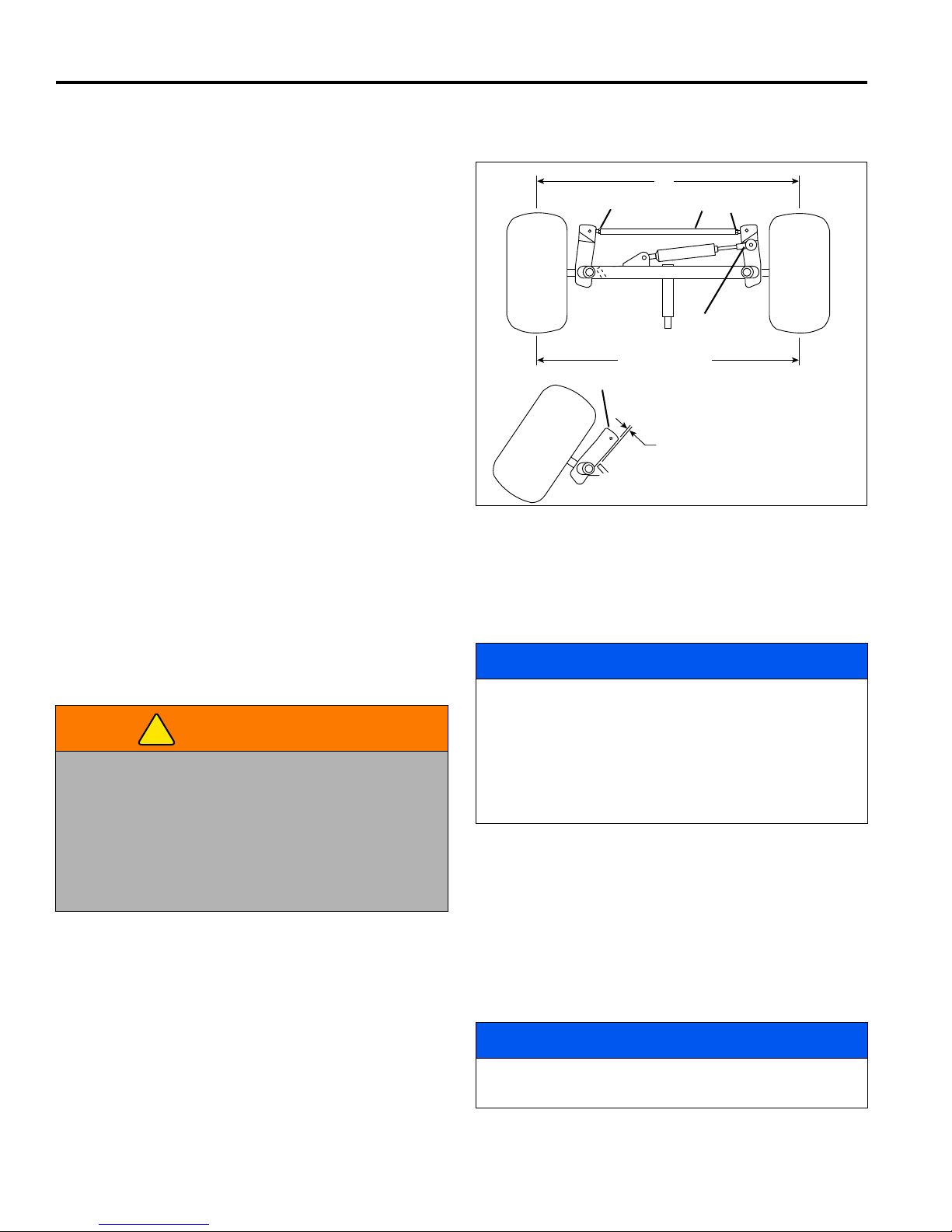
8 REGOLAZIONI
19 ± 1,5 mm
N
S
T
U
P
K +0 - 1,5 mm
R
LF016
N
!
8.6 RILEVAMENTO DELLA STERZATA ___________________________________________
1. Allineare le ruote in avanti.
2. Allentare i dadi di blocco (N) su entrambi i lati della barra
di accoppiamento (M).
3. Ruotare la barra di accoppiamento (S) per fornire la giusta
convergenza. La convergenza non deve superare +1,5
mm (P). Stringere di nuovo i dadi di bloccaggio.
4. Dopo aver regolato la barra di accoppiamento, regolare il
cilindro dello sterzo svitando la barra (T) all’interno a al di
fuori del giunto sferico in modo che il braccio del fusello
(R) liberi l'arresto sull'assale per un valore tra da 19 ± 1,5
mm (U) quando il cilindro è completamente esteso.
Figura 8E
8.7 TARATURA DEL SISTEMA DI COMANDO DELLA TRAZIONE ______________________
Il sistema di comando della trazione (TCS) deve essere tarato
in seguito alla sostituzione di un suo componente, o in caso di
cattivo funzionamento del sistema stesso. È composto da:
controller, valvola di sollevamento, cilindri di sollevamento o
tubi flessibili.
1. Lasciare riscaldare bene l’impianto idraulico. Durante la
taratura l’operatore deve essere seduto alla postazione di
guida.
AVVERTENZA
Non azionate mai il motore senza adeguata ventilazione;
l’inalazione dei gas di scarico può essere micidiale.
Le lame dell’apparato di taglio girano durante la fase di
riscaldamento dell’impianto idraulico per la taratura.
Verificare che la zona sotto ed attorno agli apparati di taglio
sia pulita e priva di detriti che possano essere lanciati dalla
macchina. Tenere gli astanti a distanza di sicurezza dalla
macchina.
a. Avviare il motore e regolare l’acceleratore alla mas-
b. Rilasciare il freno di stazionamento.
c. Attivare la PDF.
d. Abbassare completamente al suolo gli apparati di
e. Inserire il sistema di comando della trazione.
f. Lasciare girare l’unità per 5 minuti a queste impostazi-
2. La taratura del sistema deve essere effettuata a motore
acceso, con l’operatore al posto di guida, il commutatore
della PTO in posizione OFF (Spento), il freno di stazionamento inserito e il pedale della trazione in folle.
3. Abbassate completamente gli apparati di taglio.
Controllare che tutti e cinque gli apparati di taglio siano
completamente abbassati.
sima.
taglio.
oni.
4. Tenete premuto il comando della trazione per 5 secondi.
L’avvisatore acustico suona quando il controller inizia la
taratura.
AVVISO
Non rilasciare l’interruttore prima che l’avvisatore acustico
sia disattivato per entrambe le operazioni di inizio e fine
taratura.
Eseguire le voci 5 e 6 con calma. Se gli apparati di taglio
non iniziano a sollevarsi alla voce 5 e non sono
completamente abbassati durante la voce 6, l’impianto non
sarà tarato correttamente.
5. Picchiettare la leva di sollevamento in posizione di
sollevamento ed attendere da 3 a 5 secondi.
All’occorrenza ripetere l’operazione fin quando gli apparati
di taglio iniziano appena a sollevarsi.
6. Picchiettare la leva sinistra per abbassarla, ed attendere
che gli apparati di taglio si siano fermati. Ripetere
l’operazione, all’occorrenza picchiettando il joystick, fin
quando gli apparati di taglio frontali non si abbassano al
suolo.
7. Tenete premuto il comando della trazione finché non udite
l’avvisatore acustico. Il sistema è tarato
.
AVVISO
Per annullare la taratura, girate l’interruttore a chiave in
posizione OFF (Spento).
it-44
 Loading...