

Page 1

Technical
Manual
When Performance Matters.
™
WARNING
If incorrectly used, this machine can cause severe injury. Those who use
and maintain this machine should be trained in its proper use, warned of its
dangers, and should read the entire manual before attempting to set up,
operate, adjust, or service the machine.
Eclipse® 2
4260472-Rev A
InCommand
63334 – Eclipse 2 118, 18” 11 Blade Reel, Gen-Set
63343 – Eclipse 2 118, 18” 11 Blade Reel, Battery Pack
63335 – Eclipse 2 118, 18” 15 Blade Reel, Gen-Set
63344 – Eclipse 2 118, 18” 15 Blade Reel, Battery Pack
63336 – Eclipse 2 118F, Floating 18” 11 Blade Reel, Gen-Set
63345 – Eclipse 2 118F, Floating 18” 11 Blade Reel, Battery Pack
63337 – Eclipse 2 118F, Floating 18” 15 Blade Reel, Gen-Set
63346 – Eclipse 2 118F, Floating 18” 15 Blade Reel, Battery Pack
63338 – Eclipse 2 122, 22” 11 Blade Reel, Gen-Set
63347 – Eclipse 2 122, 22” 11 Blade Reel, Battery Pack
63339 – Eclipse 2 122, 22” 15 Blade Reel, Gen-Set
63348 – Eclipse 2 122, 22” 15 Blade Reel, Battery Pack
63340 – Eclipse 2 122F, Floating 22” 11 Blade Reel, Gen-Set
63349 – Eclipse 2 122F, Floating 22” 11 Blade Reel, Battery Pack
63341 – Eclipse 2 122F, Floating 22” 15 Blade Reel, Gen-Set
63350 – Eclipse 2 122F, Floating 22” 15 Blade Reel, Battery Pack
63342 – Eclipse 2 126, 26” 7 Blade Reel, Gen-Set
63351 – Eclipse 2 126, 26” 7 Blade Reel, Battery Pack
™
GB
Page 2
11524 WILMAR BLVD,
CHARLOTTE, NC 28273
®
kg kW
1-800-848-1636 (US)
PRODUCT OF U.S.A.
A Textron Company
FOREWORD
This manual contains safety, operating, adjustment,
maintenance, troubleshooting instructions and parts list
for your new Jacobsen machine. This manual should be
stored with the equipment for reference during operation.
Before you operate your machine, you and each operator
you employ should read the manual carefully in its
entirety. By following the safety, operating and
maintenance instructions, you will prolong the life of your
equipment and maintain its maximum efficiency.
If additional information is needed, contact your
Jacobsen Dealer.
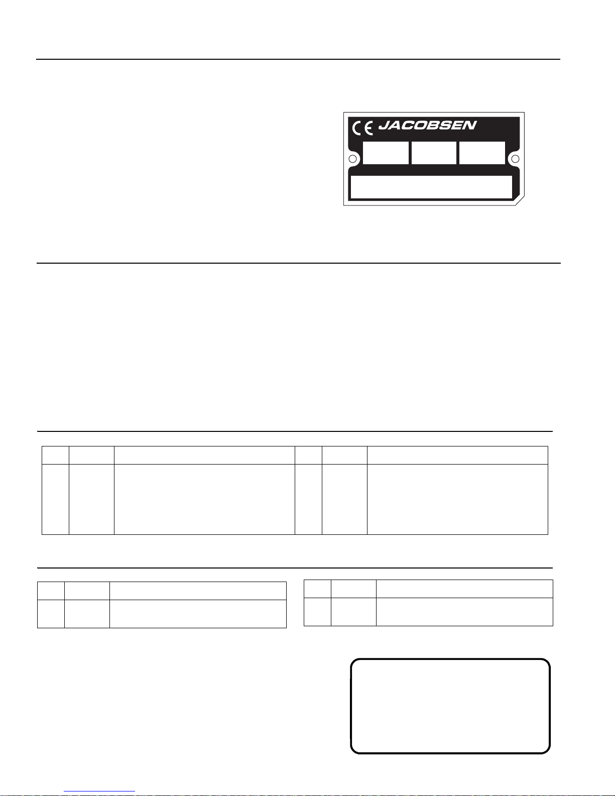
The serial plate is located on the rear crossbar of the
frame. Jacobsen recommends you record these numbers
below for easy reference.
Suggested Stocking Guide
To Keep your Equipment fully operational and productive, Jacobsen suggests you maintain a stock of the more
commonly used maintenance items. We have included part numbers for additional support materials and training aids.
To order any of the following material:
1. Write your full name and complete address on your
order form.
2. Explain where and how to make shipment:
3. Order by the quantity desired, the part number, and
the description of the part.
4. Send or bring the order to your authorized Jacobsen
Dealer.
❑ UPS ❑ Regular Mail
❑ Overnight ❑ 2nd Day
Service Parts
Qty. Part No. Description Qty. Part No. Description
4102780 50 Amp Fuse 2811106 Motor to Pulley Belt
4262910 30 Amp Fuse 2811070 Pulley to Traction Drum Belt
4131618 Ignition Key
Service Support Material
Qty. Part No. Description
4260472 Technical Manual
4260475 Operator Training Video
Qty. Part No. Description
4262930 Floating Head Service Manual
4262932 Fixed Head Service Manual
These are the original instructions verified by
Jacobsen, A Textron Company.
© 2012, Jacobsen, A Textron Company/Textron Innovations Inc.
“All rights reserved, including the right to reproduce this material
2
or portions thereof in any form.”
Proposition 65 Warning
This product contains or emits
chemicals known to State of California
to cause cancer and birth defects or
other reproductive harm.
LITHO IN U.S.A. 6-2012
Page 3

Table of Contents
1SAFETY
1.1 Operating Safety . . . . . . . . . . . . . . . . . . . . . . 4
1.2 Important Safety Notes . . . . . . . . . . . . . . . . . 5
2 SPECIFICATIONS
2.1 Product Identification . . . . . . . . . . . . . . . . . . 6
2.2 Mower . . . . . . . . . . . . . . . . . . . . . . . . . . . . . . 7
2.3 Traction and Differential . . . . . . . . . . . . . . . . 7
2.4 Weights . . . . . . . . . . . . . . . . . . . . . . . . . . . . . 7
2.5 Gen-Set Power Module . . . . . . . . . . . . . . . . 7
2.6 Battery Power Module . . . . . . . . . . . . . . . . . 8
2.7 Accessories & Support Literature . . . . . . . . . 9
2.8 Declaration of Conformity . . . . . . . . . . . . . . 10
3DECALS
3.1 Decals . . . . . . . . . . . . . . . . . . . . . . . . . . . . . 13
4 CONTROLS
4.1 Icons . . . . . . . . . . . . . . . . . . . . . . . . . . . . . . 16
4.2 Handle Controls . . . . . . . . . . . . . . . . . . . . . 16
4.3 LCD Display . . . . . . . . . . . . . . . . . . . . . . . . 17
4.4 Frequency of Cut . . . . . . . . . . . . . . . . . . . . 22
4.5 Gas Power Module Controls . . . . . . . . . . . . 27
4.6 Battery Power Module Controls . . . . . . . . . 27
5 OPERATION
5.1 Daily Inspection . . . . . . . . . . . . . . . . . . . . . 28
5.2 Interlock System (O.P.C.) . . . . . . . . . . . . . . 28
5.3 Operating Procedures . . . . . . . . . . . . . . . . . 29
5.4 Starting/Stopping . . . . . . . . . . . . . . . . . . . . 30
5.5 Mowing . . . . . . . . . . . . . . . . . . . . . . . . . . . . 31
5.6 Transport Wheels (Optional) . . . . . . . . . . . . 32
5.7 Kickstand . . . . . . . . . . . . . . . . . . . . . . . . . . 32
5.8 Grass Catcher . . . . . . . . . . . . . . . . . . . . . . . 33
5.9 Daily Maintenance . . . . . . . . . . . . . . . . . . . 33
6 ADJUSTMENTS (ALL UNITS)
6.1 General . . . . . . . . . . . . . . . . . . . . . . . . . . . . 34
6.2 Brake . . . . . . . . . . . . . . . . . . . . . . . . . . . . . 34
6.3 Speed Paddle Stops . . . . . . . . . . . . . . . . . . 34
6.4 Handle . . . . . . . . . . . . . . . . . . . . . . . . . . . . 35
6.5 Traction Belts . . . . . . . . . . . . . . . . . . . . . . . 35
6.6 Front Roller Weight . . . . . . . . . . . . . . . . . . . 36
6.7 Torque Specification . . . . . . . . . . . . . . . . . . 37
8 FLOATING HEAD REEL ADJUSTMENTS
8.1 General . . . . . . . . . . . . . . . . . . . . . . . . . . . .40
8.2 Bedknife-To-Reel . . . . . . . . . . . . . . . . . . . . .40
8.3 Bedknife Adjustment . . . . . . . . . . . . . . . . . .41
8.4 Reel Bearing . . . . . . . . . . . . . . . . . . . . . . . . 41
8.5 Cutting Height . . . . . . . . . . . . . . . . . . . . . . . 42
8.6 Reel Assembly Removal . . . . . . . . . . . . . . .42
9 BATTERY POWER MODULE
9.1 Safety . . . . . . . . . . . . . . . . . . . . . . . . . . . . . 43
9.2 General . . . . . . . . . . . . . . . . . . . . . . . . . . . .43
9.3 Maintenance . . . . . . . . . . . . . . . . . . . . . . . .44
9.4 Cleaning Batteries . . . . . . . . . . . . . . . . . . . . 44
9.5 Battery Charger . . . . . . . . . . . . . . . . . . . . . . 45
9.6 Battery Installation . . . . . . . . . . . . . . . . . . . .46
9.7 Replacing Battery Pack . . . . . . . . . . . . . . . . 47
10 GEN-SET POWER MODULE
10.1 Engine . . . . . . . . . . . . . . . . . . . . . . . . . . . . . 48
10.2 Engine Oil . . . . . . . . . . . . . . . . . . . . . . . . . .48
10.3 Engine Oil Change . . . . . . . . . . . . . . . . . . . .49
10.4 Engine Speed . . . . . . . . . . . . . . . . . . . . . . .49
10.5 Fuel . . . . . . . . . . . . . . . . . . . . . . . . . . . . . . .50
11 MAINTENANCE
11.1 General . . . . . . . . . . . . . . . . . . . . . . . . . . . . 51
11.2 Tires (Option) . . . . . . . . . . . . . . . . . . . . . . . .51
11.3 Wheel Bearing . . . . . . . . . . . . . . . . . . . . . . .51
11.4 Backlapping and Grinding . . . . . . . . . . . . . .52
11.5 Storage . . . . . . . . . . . . . . . . . . . . . . . . . . . .53
12 TROUBLESHOOTING
12.1 General . . . . . . . . . . . . . . . . . . . . . . . . . . . . 54
13 MAINTENANCE & LUBRICATION CHARTS
13.1 General . . . . . . . . . . . . . . . . . . . . . . . . . . . . 55
13.2 Maintenance Chart . . . . . . . . . . . . . . . . . . . 55
13.3 Lubrication Chart . . . . . . . . . . . . . . . . . . . . 56
14 PARTS CATALOG
14.1 How To Use The Parts Catalog . . . . . . . . . .57
14.2 To Order Parts . . . . . . . . . . . . . . . . . . . . . . . 57
14.3 Parts Catalog Table of Contents . . . . . . . . .57
7 FIXED HEAD REEL ADJUSTMENTS
7.1 General . . . . . . . . . . . . . . . . . . . . . . . . . . . . 38
7.2 Reel To Bedknife . . . . . . . . . . . . . . . . . . . . 38
7.3 Bedknife Adjustment . . . . . . . . . . . . . . . . . . 39
7.4 Cutting Height . . . . . . . . . . . . . . . . . . . . . . . 39
3
Page 4

1 SAFETY
!
1 SAFETY
1.1 OPERATING SAFETY ______________________________________________________
WARNING
EQUIPMENT OPERATED IMPROPERLY OR BY UNTRAINED PERSONNEL CAN BE DANGEROUS.
Familiarize yourself with the location and proper use of all controls. Inexperienced operator’s should receive
instruction from someone familiar with the equipment before being allowed to operate the machine.
1. Safety is dependent upon the awareness, concern
and prudence of those who operate or service the
equipment. Never allow minors to operate any
equipment.
2. It is your responsibility to read this manual and all
publications associated with this equipment (Engine
Manual, Battery Charger Manual, accessories, and
attachments). If the operator cannot read English it
is the owner’s responsibility to explain the material
contained in this manual to them.
3. Learn the proper use of the machine, the location
and purpose of all the controls before you operate
the equipment. Working with unfamiliar equipment
can lead to accidents.
4. Never allow anyone to operate or service the
machine or its attachments without proper training
and instructions; or while under the influence of
alcohol or drugs.
5. Wear all the necessary protective clothing and
personal safety devices to protect your head, eyes,
ears, hands, and feet. Long hair, loose clothing, or
jewelry may get tangled in moving parts. Operate
the machine only in daylight or in good artificial light.
6. Evaluate the terrain to determine what accessories
and attachments are needed to properly and safely
perform the job. Only use accessories and
attachments approved by Jacobsen.
7. Stay alert for holes in the terrain and other hidden
hazards.
8. Inspect the area where the equipment will be used.
Pick up all the debris you can find before operating.
Beware of overhead obstructions (low tree limbs,
electrical wires, etc.) and also underground
obstacles (sprinklers, pipes, tree roots, etc.) Enter a
new area cautiously. Stay alert for hidden hazards.
9. Do not carry passengers. Keep bystanders and pets
a safe distance away.
10. Never direct discharge of material toward
bystanders, nor allow anyone near the machine
while in operation. The owner/operator can prevent
and is responsible for injuries inflicted to
themselves, to bystanders, and damage to property.
This machine is to be operated and maintained as specified in this manual and is intended for the professional
maintenance of specialized turf grasses. It is not intended for use on rough terrain or long grasses.
11. Never operate equipment that is not in perfect
working order or is without decals, guards, shields,
discharge deflectors, or other protective devices
securely fastened in place.
12. Never disconnect or bypass any switch.
13. Keep the unit clean. Disconnect the power
connector before storing. Do not store unit near an
open flame or flammable debris.
14. Place unit on a flat surface, disengage all drives,
and engage parking brake before energizing the
unit.
15. Local regulations may restrict the age of the
operator.
16. Operate the machine across the face of the slope
(horizontally), not up and down the slope (vertically).
Never operate on wet grass.
17. Always operate at speeds that allow you to have
complete control of the machine. Be sure of your
footing, keep a firm hold on the handle, and walk,
never run.
Gen-Set Power Module
18. Carbon monoxide in the exhaust fumes can be fatal
when inhaled. Never operate the engine without
proper ventilation.
19. Fuel is highly flammable, handle with care. See
Section 5.9 .
20. Before you clean, adjust or repair this equipment,
stop the engine, disconnect the spark plug wire, and
keep the wire away from the plug to prevent
accidental starting. Disconnect the power connector.
21. Keep the engine clean. Allow the engine to cool,
always close fuel shut off valve, and remove the
spark plug wire from the spark plug before storing.
Do not store unit near an open flame or flammable
debris.
Battery Power Module
22. Before you clean, adjust, or repair this equipment,
disconnect the power connector.
23. Do not remove battery pack without unit on
kickstand.
4
Page 5
SAFETY 1
!
!
1.2 IMPORTANT SAFETY NOTES ________________________________________________
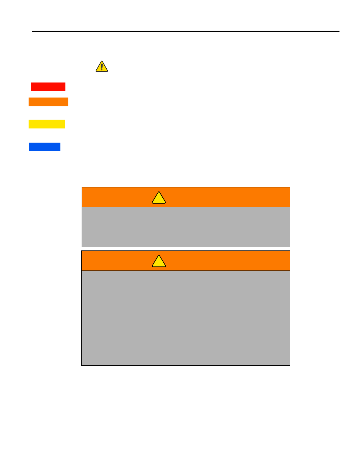
This safety alert symbol is used to alert you to potential hazards.
DANGER - Indicates an imminently hazardous situation which, if not avoided, WILL result in death or serious injury.
WARNING - Indicates a potentially hazardous situation which, if not avoided, COULD result in death or serious
injury.
CAUTION - Indicates a potentially hazardous situation which, if not avoided, MAY result in minor or moderate injury
and property damage. It may also be used to alert against unsafe practices.
NOTICE - Indicates a potentially hazardous situation which, if not avoided, MAY result in property damage. It may
also be used to alert against unsafe practices.
For pictorial clarity, some illustrations in this manual may show shields, guards or plates open or removed. Under no
circumstances should this equipment be operated without these devices securely fastened in place.
WARNING
The Interlock System on this machine will shut off the reel and traction drive
if the operator releases the O.P.C. (Operator Presence Control) bail.
To protect the operator and others from injury, never operate equipment with
the Interlock System disconnected or malfunctioning.
WARNING
1. Before leaving the operator’s position for any reason:
a. Disengage all drives.
b. Engage parking brake.
c. Disconnect power connector.
2. Keep hands, feet, and clothing away from moving parts. Wait for all
movement to stop before you clean, adjust, or service the machine.
3. Keep the area of operation clear of all bystanders and pets.
4. Chock or block the wheels if the machine is left on an incline.
5. Never operate mowing equipment without the discharge deflector
securely fastened in place.
By following all instructions in this manual, you will prolong the life of your machine and maintain its maximum
efficiency. Adjustments and maintenance should always be performed by a qualified technician.
If additional information or service is needed, contact your Authorized Jacobsen Dealer who is kept informed of the
latest methods to service this equipment and can provide prompt and efficient service.
5
Page 6
2 SPECIFICATIONS
92.3 2.6 XXXX
63334001651
2 SPECIFICATIONS
2.1 PRODUCT IDENTIFICATION_________________________________________________
63334............................ Eclipse® 118 base unit with 18 in.
(457 mm) 11 blade reel and
InCommand™ control system.
Gen-Set power module.
®
63343............................ Eclipse
118 base unit with 18 in.
(457 mm) 11 blade reel and
InCommand™ control system.
Battery power module.
®
63335............................ Eclipse
118 base unit with 18 in.
(457 mm) 15 blade reel and
InCommand™ control system.
Gen-Set power module.
®
63344............................ Eclipse
118 base unit with 18 in.
(457 mm) 15 blade reel and
InCommand™ control system.
Battery power module.
®
63336............................ Eclipse
118F base unit with
floating 18 in. (457 mm) 11 blade
reel and InCommand™ control
system. Gen-Set power module.
®
63345............................ Eclipse
118F base unit with
floating 18 in. (457 mm) 11 blade
reel and InCommand™ control
system. Battery power module.
®
63337............................ Eclipse
118F base unit with
floating 18 in. (457 mm) 15 blade
reel and InCommand™ control
system. Gen-Set power module.
®
63346............................ Eclipse
118F base unit with
floating 18 in. (457 mm) 15 blade
reel and InCommand™ control
system. Battery power module.
®
63338............................ Eclipse
122 base unit with 22 in.
(559 mm) 11 blade reel and
InCommand™ control system.
Gen-Set power module.
®
63347............................ Eclipse
122 base unit with 22 in.
(559 mm) 11 blade reel and
InCommand™ control system.
Battery power module.
®
63339............................ Eclipse
122 base unit with 22 in.
(559 mm) 15 blade reel and
InCommand™ control system.
Gen-Set power module.
®
63348............................ Eclipse
122 base unit with 22 in.
(559 mm) 15 blade reel and
InCommand™ control system.
Battery power module.
®
63340............................ Eclipse
122F base unit with
floating 22 in. (457 mm) 11 blade
reel and InCommand™ control
system. Gen-Set power module.
63349.............................Eclipse
floating 22 in. (457 mm) 11 blade
reel and InCommand™ control
system. Battery power module.
63341.............................Eclipse
floating 22 in. (457 mm) 15 blade
reel and InCommand™ control
system. Gen-Set power module.
63350.............................Eclipse
floating 22 in. (457 mm) 15 blade
reel and InCommand™ control
system. Battery power module.
63342.............................Eclipse
(660 mm) 7 blade reel and
InCommand™ control system.
Gen-Set power module.
63351.............................Eclipse
(660 mm) 7 blade reel and
InCommand™ control system.
Battery power module.
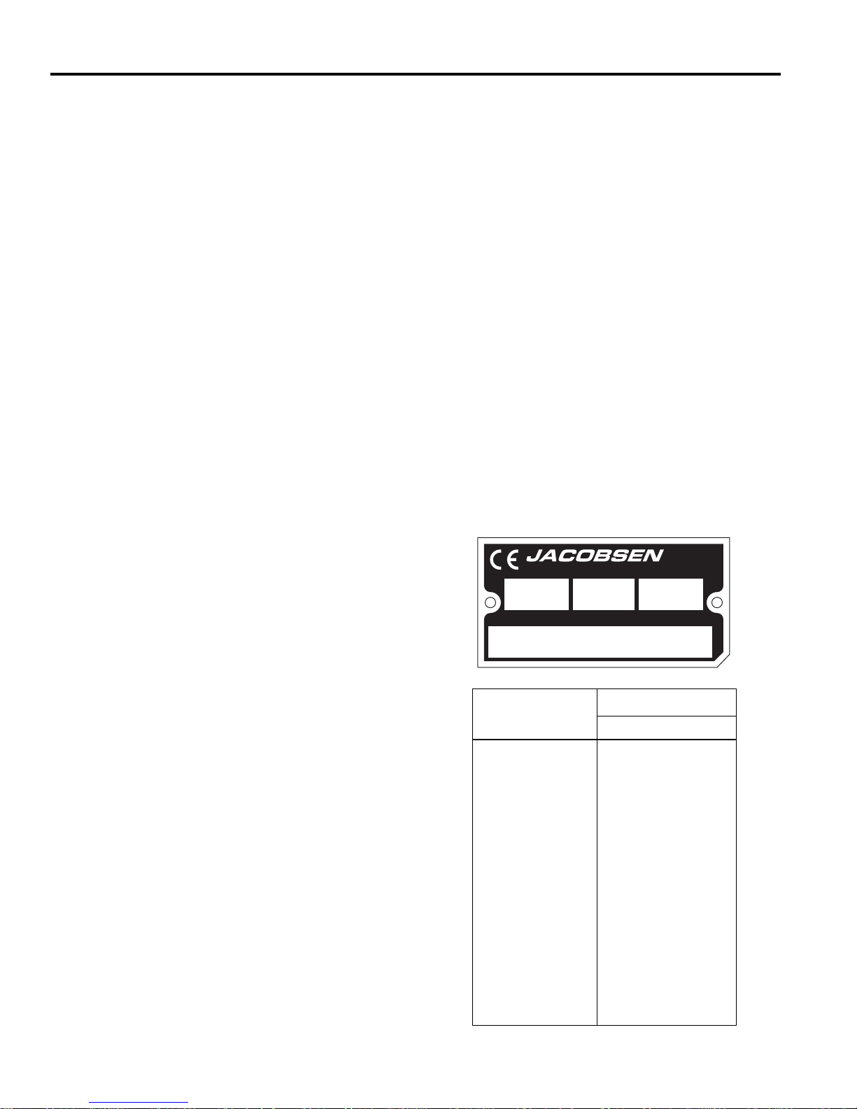
Serial Number ..............An identification plate, like the one
shown, listing the serial number, is
attached to the rear crossbar.
PRODUCT OF U.S.A.
kg kW
Product
63334
63335
63336
63337
63338
63339
63340
63341
63342
63343
63344
63345
63346
63347
63348
63349
63350
63351
®
122F base unit with
®
122F base unit with
®
122F base unit with
®
126 base unit with 26 in.
®
126 base unit with 26 in.
®
11524 WILMAR BLVD,
A Textron Company
Vibration M/S
CHARLOTTE, NC 28273
1-800-848-1636 (US)
2
Arms
4.25 ± 1.3
4.25 ± 1.3
4.83 ± 1.3
4.83 ± 1.3
2.37 ± 1.3
2.37 ± 1.3
4.44 ± 1.3
4.44 ± 1.3
2.84 ± 1.3
1.44 ± 1.3
1.44 ± 1.3
0.90 ± 1.3
0.90 ± 1.3
1.00 ± 1.3
1.00 ± 1.3
1.07 ± 1.3
1.07 ± 1.3
0.89 ± 1.3
6
Page 7

SPECIFICATIONS 2
2.2 MOWER__________________________________________________________________
Reel..................................7, 9, 11, or 15 blades, hardened
high manganese carbon steel.
Reel Diameter .................. 5 in. (127 mm)
Cutting Width ...................18, 22 or 26 in. (457, 559 or
660 mm)
Height of cut.....................1/16 to 7/16 in. (1.6 to 11 mm)
Bedknives.........................Hardened carbon steel
High Profile ................5/32” - 7/16” (4 - 11 mm) cut
Low Profile................. 1/8” - 7/32” (3.2 - 5.6 mm) cut
Tournament................ 3/32” - 5/32” (2.4 - 4 mm) cut
Super Tournament ..... 5/64” - 7/64” (2.1 - 2.8 mm) cut
Championship............ 1/16” - 7/64” (1.6 - 2.8 mm) cut
Frequency of Cut
15 Blade Reel ............ 0.064 - 0.133 in. (1.6 - 3.4 mm)
11 Blade Reel ............ 0.087 - 0.178 in. (2.2 - 4.5 mm)
9 Blade Reel .............. 0.106 - 0.217 in. (2.7 - 5.5 mm)
2.3 TRACTION AND DIFFERENTIAL ______________________________________________
Transport Tires (Option) ... 11 x 4 pneumatic bidirectional.
Reel Drive ........................Independent direct drive motor.
Traction Drive ...................Independent drive motor with two
synchronous polyurethane belts.
Traction Reduction Ratio..15.15:1
Mowing speed.................. 0 - 3.4 m.p.h. (5.31 km/h)
Differential........................ Full automotive type, housed in
traction drum
Rear Drive Drum.............. Machined aluminum alloy
2 Section, 7-3/4 (O.D.) x 10-31/32
2.4 WEIGHTS ________________________________________________________________
Gen Set Mowers
Weights: Without Grass Catcher Lbs. (kg)
63334 – Eclipse 118 11 Blade .................. 214 (97.1)
63335 – Eclipse 118 15 Blade .................. 217 (98.4)
63336 – Eclipse 118F 11 Blade ................ 254 (115.2)
63337 – Eclipse 118F 15 Blade ................ 257 (116.6)
63338 – Eclipse 122 11 Blade .................. 221 (100.2)
63339 – Eclipse 122 15 Blade .................. 224 (101.6)
63340 – Eclipse 122F 11 Blade ................ 265 (120.2)
63341 – Eclipse 122F 15 Blade ................ 268 (121.6)
63342 – Eclipse 126 .................................. 243 (110.2)
Battery Pack Mowers
Weights: Without Grass Catcher Lbs. (kg)
63343 – Eclipse 118 11 Blade .................. 234 (106.1)
63344 – Eclipse 118 15 Blade .................. 237 (107.5)
63345 – Eclipse 118F 11 Blade ................ 274 (124.3)
63346 – Eclipse 118F 15 Blade ................ 277 (125.6)
63347 – Eclipse 122 11 Blade .................. 241 (109.3)
63348 – Eclipse 122 15 Blade .................. 244 (110.7)
63349 – Eclipse 122F 11 Blade ................ 285 (129.3)
63350 – Eclipse 122F 15 Blade ................ 288 (130.6)
63351 – Eclipse 126 ................................. 263 (119.3)
With Steel Grooved Roller 68618
With Machined Aluminum Grooved Roller 68614
With Machined Aluminum Grooved Roller 68617
2.5 GEN-SET POWER MODULE _________________________________________________
Engine..............................Honda GX-120 K1Q JG2 4-Cycle,
4HP (2.98 kW) at 4000 RPM
Speed...............................Engine speed set at factory for
generator to produce 59.8 volts
with no load. (2750 to 3250 rpm)
Fuel .................................. Regular Grade (Unleaded)
Fuel Tank .........................0.66 Gallon (2.5 liter)
Use clean, fresh, regular unleaded gasoline, 85 octane
minimum. Refer to the engine’s operator manual for fuel
recommendations when using blended fuel.
7
Page 8

2 SPECIFICATIONS
2.6 BATTERY POWER MODULE ________________________________________________
To ensure the longest battery life possible, the batteries
are not shipped with the power module and must be
ordered separately. For optimum range and performance
use batteries that equal or exceed the Amp-hour rating
listed.
System Voltage............. 48 Volt DC
Batteries ...................... (4) 12 volt, valve regulated,
non-spillable sealed lead acid
batteries.
Charger......................... 5 Amp, 48 Volt DC, dual input
voltage 115/230 Volt AC, 50/60
Hz.
Recommended Battery:
CSB battery is the Jacobsen recommended battery for
use in the Eclipse mower.
Battery Brand Battery Part Number
CSB EVX12200
Length
in. (mm)
7-1/8
(181)
Width
in. (mm)
3
(76)
Height
in. (mm)
6-9/16
(167)
Weight
lbs. (kg)
14.7
(6.7)
Rating
Amp-Hr
20 12 4
Volt s
Qty
Req’d
Alternate Batteries:
These alternate batteries are also currently available.
These batteries have the same dimensions and amphour ratings, but have not been tested by Jacobsen, and
no recommendation is stated or should be implied.
Contact your local battery dealer or the manufacturer for
sourcing on these batteries.
Battery Brand
Yuasa Enersys NPX 80
Panasonic LC-X1220AP
Panasonic LC-X1220P
Discover D12200
Power Sonic PSH-12180
B.B. Battery EB20-12
Battery
Part Number
(USE ONLY 12 VOLT SLA BATTERIES)
CSB batteries can be ordered from these CSB
distributors, or from any local battery dealer.
Electronic Distributing
920 Brookstown Ave
Winston Salem, NC 27101
Phone Number - 800-777-1096
Fax Number - 336-723-1098
E-Mail - [email protected] (E-Mail)
Contact Name - Bill Turner
URS Electronics
123 N.E. 7th
Portland, OR 97232
Phone Number - 800-955-4877
Fax Number - 503-232-3373
E-Mail - [email protected]
Contact Name - Mark Twietmeyer
8
Page 9

SPECIFICATIONS 2
!
2.7 ACCESSORIES & SUPPORT LITERATURE _____________________________________
Contact your area Jacobsen Dealer for a complete listing of accessories and attachments.
CAUTION
Use of other than Jacobsen authorized parts and accessories may cause personal injury or damage to the
equipment.
Accessories
Lapping Compound (180 grit) ................................... 554598
Orange Touch-up Paint (12 oz. spray) ...................... 554598
18 in. Fixed Head Grass Catcher................................ 68122
18 in. Floating Head Grass Catcher........................ 4174683
22 in. Fixed Head Grass Catcher................................ 68123
22 in. Floating Head Grass Catcher........................ 4114788
26 in. Fixed Head Grass Catcher................................ 68124
22 in. Push Brush (Fixed Head Units)......................... 68611
22 in. Front Roller Brush (Fixed Head Units) .............. 68610
22 in. Front Roller Brush (Floating Head Units) .......... 68536
LED Light Kit ............................................................... 63307
Battery Charger........................................................... 68661
Removable Battery Pack ()....................................... 63316
Mower Caddy Battery Pack Mounting Kit.................... 68660
Transport Tires ............................................................ 62293
Mower Caddy ..........................................................63321
Mower Caddy 18” Mower Mounting Kit ...............4243882
Mower Caddy 22” Mower Mounting Kit ...............4243883
Mower Caddy 26” Mower Mounting Kit ...............4243884
22 in. Turf Groomer
Fixed Head Turf Groomer
®
() .........................................67966
®
Adapter Kit ...................67965
MAGKnife Kits
122F Super Tournament MAGKnife Kit................... 4188500
122F Tournament MAGKnife Kit ............................. 4158083
122 Super Tournament MAGKnife Kit..................... 4158082
Solid Rollers
18 in. with Scraper.......................................................68626
22 in. with Scraper.......................................................68530
26 in. with Scraper.......................................................68627
Grooved Rollers
18 in. Machined Steel ..................................................68616
22 in. Assembled Disc .................................................68527
22 in. Machined Aluminum ..........................................68614
22 in. Machined Steel ..................................................68613
22 in. Segmented Roller ..............................................68673
26 in. Machined Aluminum ..........................................68617
26 in. Machined Steel ..................................................68628
Floating Head Reels
22 in. 11 Blade Reel ....................................................63308
22 in. 15 Blade Reel ....................................................63333
18 in. 11 Blade Reel ....................................................63309
18 in. 15 Blade Reel ....................................................62824
Right Hand Reel Conversion Kit ..............................4172485
Left Hand Reel Conversion Kit ................................4172441
Additional Power Modules
Gen-Set Power Module................................................ 63305
Battery Power Module () ...........................................63306
Support Literature
Technical Manual.....................................................4260472
Operator Training DVD Video ..................................4260475
Fixed Head Repair Manual......................................4262932
Floating Head Repair Manual..................................4262930
Does not included batteries
Fixed Head Units require 67965 to install Turf Groomer
9
Page 10

2 SPECIFICATIONS
2.8 DECLARATION OF CONFORMITY ____________________________________________
DECLARATION OF CONFORMITY ▪ ДЕКЛАРАЦИЯ ЗА СЪОТВЕТСТВИЕ ▪ PROHLÁŠENÍ O SHODĚ ▪
OVERENSSTEMMELSESERKLÆRING ▪ CONFORMITEITSVERKLARING ▪ VASTAVUSDEKLARATSIOON ▪
VAATIMUSTENMUKAISUUSVAKUUTUS ▪ DECLARATION DE CONFORMITE ▪ KONFORMITÄTSERKLÄRUNG ▪
ΔΗΛΩΣΗ ΣΥΜΜΟΡΦΩΣΗΣ ▪ MEGFELELŐSÉGI NYILATKOZAT ▪ DICHIARAZIONE DI CONFORMITÀ ▪ ATBILSTĪBAS
DEKLARĀCIJA ▪ ATITIKTIES DEKLARACIJA ▪ DIKJARAZZJONI TAL-KONFORMITÀ ▪ DEKLARACJA ZGODNOŚCI ▪
DECLARAÇÃO DE CONFORMIDADE ▪ DECLARAŢIE DE CONFORMITATE ▪ VYHLÁSENIE O ZHODE ▪ IZJAVA O
SKLADNOSTI ▪ DECLARACIÓN DE CONFORMIDAD ▪ DEKLARATION OM ÖVERENSSTÄMMELSE
Business name and full address of the manufacturer ▪ Търговско име и пълен адрес на производителя ▪ Obchodní jméno a plná adresa výrobce ▪
Producentens firmanavn og fulde adresse ▪ Bedrijfsnaam en volledig adres van de fabrikant ▪ Tootja ärinimi ja täielik aadress ▪
Valmistajan toiminimi ja täydellinen osoite ▪ Nom commercial et adresse complète du fabricant ▪ Firmenname und vollständige Adresse des Herstellers ▪
Επωνυμία και ταχυδρομική διεύθυνση κατασκευαστή ▪ A gyártó üzleti neve és teljes címe ▪ Ragione sociale e indirizzo completo del fabbricante ▪
Uzņēmuma nosaukums un pilna ražotāja adrese ▪ Verslo pavadinimas ir pilnas gamintojo adresas ▪ Isem kummerċjali u indirizz sħiħ tal-fabbrikant ▪
Nazwa firmy i pełny adres producenta ▪ Nome da empresa e endereço completo do fabricante ▪ Denumirea comercială şi adresa completă a
producătorului ▪ Obchodný názov a úplná adresa výrobcu ▪ Naziv podjetja in polni naslov proizvajalca ▪ Nombre de la empresa y dirección completa del
fabricante ▪ Tillverkarens företagsnamn och kompletta adress
Product Code ▪ Код на
▪ Termékkód ▪ Codice prodotto ▪ Produkta kods ▪ Produkto kodas ▪ Kodiċi tal-Prodott ▪ Kod produktu ▪ Código do Produto ▪ Cod produs ▪ Kód výrobku ▪
Oznaka proizvoda ▪ Código de producto ▪ Produktkod
Machine Name ▪ Наименование на машината ▪ Název stroje ▪ Maskinnavn ▪ Machinenaam ▪ Masina nimi ▪ Laitteen nimi ▪ Nom de la machine ▪
Maschinenbezeichnung ▪ Ονομασία μηχανήματος ▪ Gépnév ▪ Denominazione della macchina ▪ Iekārtas nosaukums ▪ Mašinos pavadinimas ▪ Isem tal-
▪ Nazwa urządzenia ▪ Nome da Máquina ▪ Numele echipamentului ▪ Názov stroja ▪ Naziv stroja ▪ Nombre de la máquina ▪ Maskinens namn
Magna
Designation ▪ Предназначение ▪ Označení ▪ Betegnelse ▪ Benaming ▪ Nimetus ▪ Tyyppimerkintä ▪ Pažymėjimas ▪ Bezeichnung ▪ Χαρακτηρισμός ▪
Megnevezés ▪ Funzione ▪ Apzīmējums ▪ Lithuanian ▪ Denominazzjoni ▪ Oznaczenie ▪ Designação ▪ Specificaţie ▪ Označenie ▪ Namen stroja ▪ Descripción
▪ Beteckning
Serial Number ▪ Сериен номер ▪ Sériové číslo ▪ Serienummer ▪ Serienummer ▪ Seerianumber ▪ Valmistusnumero ▪ Numéro de série ▪ Seriennummer ▪
Σειριακός αριθμός ▪ Sorozatszám ▪ Numero di serie ▪ Sērijas numurs ▪ Serijos numeris
serie ▪ Sériové číslo ▪ Serijska številka ▪ Número de serie ▪ Serienummer
Engine ▪ Двигател ▪ Motor ▪ Motor ▪ Motor ▪ Mootor ▪ Moottori ▪ Moteur ▪ Motor ▪ Μηχανή ▪ Modulnév ▪ Motore ▪ Dzinējs ▪ Variklis ▪ Saħħa Netta Installata ▪
Silnik ▪ Motor ▪ Motor ▪ Motor ▪ Motor ▪ Motor ▪ Motor
Net Installed Power ▪ Нетна инсталирана мощност ▪ Čistý instalovaný výkon ▪ Installeret nettoeffekt ▪ Netto geïnstalleerd vermogen ▪ Installeeritud
netovõimsus ▪ Asennettu nettoteho ▪ Puissance nominale nette ▪ Installierte Nettoleistung ▪ Καθαρή εγκατεστημένη ισχύς ▪ Nettó beépített teljesítmény ▪
Potenza netta installata ▪ Paredzētā tīkla jauda ▪ Grynoji galia ▪ Wisa’ tal-Qtugħ ▪ Moc zainstalowana netto ▪ Potência instalada ▪ Puterea instalată netă ▪
Čistý inštalovaný výkon ▪ Neto vgrajena moč ▪ Potencia instalada neta ▪ Nettoeffekt
продукта ▪ Kód výrobku ▪ Produktkode ▪ Productcode ▪ Toote kood ▪ Tuotekoodi ▪ Code produit ▪ Produktcode ▪ Κωδικός προϊόντος
▪ Numru Serjali ▪ Numer seryjny ▪ Número de Série ▪ Număr de
Jacobsen, A Textron Company
11524 Wilmar Blvd.
Charlotte, NC 28273, USA
63334
63335
63336
63337
63338
63339
63340
63341
63342
63343
63344
63345
63346
63347
63348
63349
63350
63351
®
118 Hybrid 11 Blade
Eclipse
®
118 Hybrid 15 Blade
Eclipse
®
118F Hybrid 11 Blade
Eclipse
®
118F Hybrid 15 Blade
Eclipse
®
122 Hybrid 11 Blade
Eclipse
®
122 Hybrid 15 Blade
Eclipse
®
122F Hybrid 11 Blade
Eclipse
®
122F Hybrid 15 Blade
Eclipse
®
126 Hybrid 7 Blade
Eclipse
®
118 Battery 11 Blade
Eclipse
®
118 Battery 15 Blade
Eclipse
®
118F Battery 11 Blade
Eclipse
®
118F Battery 15 Blade
Eclipse
®
122 Battery 11 Blade
Eclipse
®
122 Battery 15 Blade
Eclipse
®
122F Battery 11 Blade
Eclipse
®
122F Battery 15 Blade
Eclipse
®
Eclipse
126 Battery 7 Blade
Lawnmower, Article 12, Item 32
6333401651-6333404500
6333501651-6330104500
6333601651-6330204500
6333701651-6330304500
6333801651-6330404500
6333901651-6331104500
6334001651-6331204500
6334101651-6334304500
6334201651-6331404500
6334301651-6331504500
6334401651-6332504500
6334501651-6332604500
6334601651-6333504500
6334701651-6332804500
6334801651-6332904500
6334901651-6333004500
6335001651-6333104500
6335101651-6333204500
Hybrid Models
Honda GX-120 Gas
Battery Models
Aspen Motor 48V Brushless DC
Hybrid Models
2,98 kW @ 3000 RPM
Battery Models
1,3 kW @ 2200 RPM
10
Page 11

SPECIFICATIONS 2
Cutting Width ▪ Широчина на рязане ▪ Šířka řezu ▪ Skærebredde ▪ Maaibreedte ▪ Lõikelaius ▪ Leikkuuleveys ▪ Largeur de coupe ▪ Schnittbreite ▪
Μήκος μισινέζας ▪ Vágási szélesség ▪ Larghezza di taglio ▪ Griešanas platums ▪ Pjovimo plotis ▪ Tikkonforma mad-Direttivi ▪ Szerokość cięcia ▪
Largura de Corte ▪ Lăţimea de tăiere ▪ Šírka záberu ▪ Širina reza ▪ Anchura de corte ▪ Klippbredd
Conforms to Directives ▪ В съответствие с директивите ▪ Splňuje podmínky směrnic ▪ Er i overensstemmelse med direktiver ▪ Voldoet aan de richtlijnen ▪
Vastab direktiividele ▪ Direktiivien mukainen ▪ Conforme aux directives ▪ Entspricht Richtlinien ▪ Ακολουθήστε πιστά τις Οδηγίες ▪ Megfelel az irányelveknek
▪ Conforme alle Direttive ▪ Atbilst direktīvām ▪ Atitinka direktyvų reikalavimus ▪ Valutazzjoni tal-Konformità ▪ Dyrektywy związane ▪ Cumpre as Directivas ▪
Respectă Directivele ▪ Je v súlade so smernicami ▪ Skladnost z direktivami ▪ Cumple con las Directivas ▪ Uppfyller direktiv
Conformity Assessment ▪ Оценка за съответствие ▪ Hodnocení plnění podmínek ▪ Overensstemmelsesvurdering ▪ Conformiteitsbeoordeling ▪
Vastavushindamine ▪ Vaatimustenmukaisuuden arviointi ▪ Evaluation de conformité ▪ Konformitätsbeurteilung ▪ Διαπίστωση Συμμόρφωσης ▪
Megfelelőség-értékelés ▪ Valutazione della conformità ▪ Atbilstības novērtējums ▪ Atitikties įvertinimas ▪ Livell tal-Qawwa tal-Ħoss Imkejjel ▪
zgodności ▪ Avaliação de Conformidade ▪ Evaluarea conformităţii ▪ Vyhodnotenie zhodnosti ▪ Ocena skladnosti ▪ Evaluación de conformidad ▪
Bedömning av överensstämmelse
Measured Sound Power Level ▪ Измерено ниво на звукова мощност ▪ Naměřený akustický výkon ▪ Målte lydstyrkeniveau ▪ Gemeten geluidsniveau ▪
Mõõdetud helivõimsuse tase ▪ Mitattu äänitehotaso ▪ Niveau de puissance sonore mesuré ▪ Gemessener Schalldruckpegel ▪
Σταθμισμένο επίπεδο ηχητικής ισχύος ▪ Mért hangteljesítményszint ▪ Livello di potenza sonora misurato ▪ Izmērītais skaņas jaudas līmenis ▪
Išmatuotas garso stiprumo lygis ▪ Livell tal-Qawwa tal-Ħoss Iggarantit ▪ Moc akustyczna mierzona ▪ Nível sonoro medido ▪ Nivelul măsurat al puterii
acustice ▪ Nameraná hladina akustického výkonu ▪ Izmerjena raven zvočne moči ▪ Nivel de potencia sonora medido ▪
Guaranteed Sound Power Level ▪ Гарантирано ниво на звукова мощност ▪ Garantovaný akustický výkon ▪ Garanteret lydstyrkeniveau ▪
Gegarandeerd geluidsniveau ▪ Garanteeritud helivõimsuse tase ▪ Taattu äänitehotaso ▪ Niveau de puissance sonore garanti ▪ Garantierter
Schalldruckpegel ▪ Εγγυημένο επίπεδο ηχητικής ισχύος ▪ Szavatolt hangteljesítményszint ▪ Livello di potenza sonora garantito ▪ Garantētais skaņas
jaudas līmenis ▪ Garantuotas garso stiprumo lygis ▪ Livell tal-Qawwa tal-Ħoss Iggarantit ▪ Moc akustyczna gwarantowana ▪ Nível sonoro farantido ▪
Nivelul garantat al puterii acustice ▪ Garantovaná hladina akustického výkonu ▪ Zajamčena raven zvočne moči ▪ Nivel de potencia sonora garantizado ▪
Garanterad ljudeffektsnivå
Conformity Assessment Procedure (Noise) ▪ Оценка за съответствие на процедурата (Шум) ▪
Procedure for overensstemmelsesvurdering (Støj) ▪ Procedure van de conformiteitsbeoordeling (geluid) ▪ Vastavushindamismenetlus (müra) ▪
Vaatimustenmukaisuuden arviointimenettely (Melu) ▪ Procédure d’évaluation de conformité (bruit) ▪ Konformitätsbeurteilungsverfahren (Geräusch) ▪
Διαδικασία Αξιολόγησης Συμμόρφωσης (Θόρυβος) ▪ Megfelelőség-értékelési eljárás (Zaj) ▪ Procedura di valutazione della conformità (rumore) ▪
Atbilstības novērtējuma procedūra (troksnis) ▪ Atitikties įvertinimo procedūra (garsas) ▪ Proċedura tal-Valutazzjoni tal-Konformità (Ħoss) ▪
Procedura oceny zgodności (poziom hałasu) ▪ Processo de avaliação de conformidade (nível sonoro) Procedura de evaluare a conformităţii (zgomot) ▪
Postup vyhodnocovania zhodnosti (hluk) ▪ Postopek za ugotavljanje skladnosti (hrup) ▪ Procedimiento de evaluación de conformidad (ruido) ▪
Procedur för bedömning av överensstämmelse (buller)
UK Notified Body for 2000/14/EC ▪ Нотифициран орган в Обединеното кралство за 2000/14/ЕО ▪ Úřad certifikovaný podle směrnice
Det britiske bemyndigede organ for 2001/14/EF ▪ Engels adviesorgaan voor 2000/14/EG ▪ Ühendkuningriigi teavitatud asutus direktiivi 2000/14/EÜ
mõistes ▪ Direktiivin 2000/14/EY mukainen ilmoitettu tarkastuslaitos Isossa-Britanniassa ▪ Organisme notifié concernant la directive 2000/14/CE ▪
Britische benannte Stelle für 2000/14/EG ▪ Κοινοποιημένος Οργανισμός Ηνωμένου Βασιλείου για 2000/14/ΕΚ ▪
2000/14/EK – egyesült királyságbeli bejelentett szervezet ▪ Organismo Notificato in GB per 2000/14/CE ▪ 2000/14/EK AK reģistrētā organizācija ▪
JK notifikuotosios įstaigos 2000/14/EC ▪ Korp Notifikat tar-Renju Unit għal 2000/14/KE ▪ Dopuszczona jednostka badawcza w Wielkiej Brytanii wg 2000/
14/WE ▪ Entidade notificada no Reino Unido para 2000/14/CE ▪ Organism notificat în Marea Britanie pentru 2000/14/CE ▪
Notifikovaný orgán Spojeného kráľovstva pre smernicu 2000/14/ES ▪ Britanski priglašeni organ za 2000/14/ES ▪
Cuerpo notificado en el Reino Unido para 2000/14/CE ▪ Anmält organ för 2000/14/EG i Storbritannien
Operator Ear Noise Level ▪ Оператор на нивото на доловим от ухото шум ▪ Hladina hluku v oblasti uší operátora ▪ Støjniveau i førers ørehøjde
Geluidsniveau oor bestuurder ▪ Müratase operaatori kõrvas ▪ Melutaso käyttäjän korvan kohdalla ▪ Niveau de bruit à hauteur des oreilles de l’opérateur ▪
Schallpegel am Bedienerohr ▪ Επίπεδο θορύβου σε λειτουργία ▪ A kezelő fülénél mért zajszint ▪ Livello di potenza sonora all’orecchio dell’operatore ▪
Trok šņa līmenis pie operatora auss ▪ Dirbančiojo su mašina patiriamo triukšmo lygis ▪ Livell tal-Ħoss fil-Widna tal-Operatur ▪
Dopuszczalny poziom hałasu dla operatora ▪ Nível sonoro nos ouvidos do operador ▪ Nivelul zgomotului la urechea operatorului ▪
Hladina hluku pôsobiaca na sluch operátora ▪ Raven hrupa pri ušesu upravljavca ▪ Nivel sonoro en el oído del operador ▪ Ljudnivå vid förarens öra
Harmonised standards used ▪ Използвани хармонизирани стандарти ▪ Použité harmonizované normy ▪ Brugte harmoniserede standarder ▪
Gebruikte geharmoniseerde standaards ▪ Kasutatud ühtlustatud standardid ▪ Käytetyt yhdenmukaistetut standardit ▪ Normes harmonisées utilisées ▪
Angewandte harmonisierte Normen ▪ Εναρμονισμένα πρότυπα που χρησιμοποιήθηκαν ▪ Harmonizált szabványok
Izmantotie saskaņotie standarti ▪ Panaudoti suderinti standartai ▪ Standards armonizzati użati ▪ Normy spójne powiązane ▪ Normas harmonizadas usadas
▪ Standardele armonizate utilizate ▪ Použité harmonizované normy ▪ Uporabljeni usklajeni standardi ▪ Estándares armonizados utilizados ▪
Harmoniserade standarder som används
Technical standards and specifications used ▪ Използвани технически стандарти и спецификации ▪ Použité technické normy a specifikace ▪
Brugte tekniske standarder og specifikationer ▪ Gebruikte technische standaards en specificaties ▪ Kasutatud tehnilised standardid ja spetsifikatsioonid ▪
Käytetyt tekniset standardit ja eritelmät ▪ Spécifications et normes techniques utilisées ▪ Angewandte technische Normen und Spezifikationen ▪
Τεχν ι κά πρότυπα και προδιαγραφές που χρησιμοποιήθηκαν ▪ Műszaki szabványok és specifikációk ▪ Standard tecnici e specifiche applicati ▪
Izmantotie tehniskie standarti un specifikācijas ▪ Panaudoti techniniai standartai ir techninė informacija ▪ Standards u speċifikazzjonijiet tekniċi użati ▪
Normy i specyfikacje techniczne powiązane ▪ Normas técnicas e especificações usadas ▪ Standardele tehnice şi specificaţiile utilizate ▪
Použité technické normy a špecifikácie ▪ Uporabljeni tehnični standardi in specifikacije ▪ Estándares y especificaciones técnicas utilizadas ▪
Tekniska standarder och specifikationer som används
The place and date of the declaration ▪ Място и дата на декларацията ▪ Místo a datum prohlášení ▪ Sted og dato for erklæringen ▪
Plaats en datum van de verklaring ▪ Deklaratsiooni väljastamise koht ja kuupäev ▪ Vakuutuksen paikka ja päivämäärä ▪ Lieu et date de la déclaration ▪
Ort und Datum der Erklärung ▪ Τόπ ος και ημερομηνία δήλωσης ▪ A nyilatkozat kelte (hely és idő) ▪ Luogo e data della dichiarazione ▪
Deklarācijas vieta un datums ▪ Deklaracijos vieta ir data ▪ Il-post u d-data tad-dikjarazzjoni ▪ Miejsce i data wystawienia deklaracji ▪ Local e data da
declaração ▪ Locul şi data declaraţiei ▪ Miesto a dátum vyhlásenia ▪ Kraj in datum izjave ▪ Lugar y fecha de la declaración ▪ Plats och datum för
deklarationen
Postup hodnocení plnění podmínek (hluk) ▪
Uppmätt ljudeffektsnivå
▪ Standard armonizzati applicati ▪
Ocena
č. 2000/14/EC ▪
▪
118, 118F - 45,7 cm
122, 122F - 55,9 cm
126 - 66,1 cm
2004/108/EC
2006/42/EC
2000/14/EC, 2005/88/EC
2006/66/EC
2006/42/EC Annex VIII
Hybrid Models - 96 dB(A) LWA
Battery Models - 86 dB(A) LWA
Hybrid Models - 95 dB(A) LWA
Battery Models - 85 dB(A) LWA
2000/14/EC Annex VI, Part 1
Sound Research Laboratories Limited
Hybrid Models
82 dB(a) Leq (2006/42/EC)
Battert Models
70 dB(a) Leq (2006/42/EC)
BS EN ISO 20643
BS EN ISO 5349-1
BS EN ISO 5349-2
BS EN 836
B71.4
ISO 2631-1
Jacobsen, A Textron Company
11524 Wilmar Blvd.
Charlotte, NC 28273, USA
February 21st, 2012
Number: 1088
Holbrook House, Little Waldingfield
Sudbury, Suffolk CO10 0TH
11
Page 12
2 SPECIFICATIONS
Signature of the person empowered to draw up the declaration on behalf of the manufacturer, holds the technical documentation and is authorised to
compile the technical file, and who is established in the Community.
Подпис на човека, упълномощен да състави декларацията от името на производителя, който поддържащ техническата документация и е
оторизиран да изготви техническия файл и е регистриран в общността.
Podpis osoby oprávněné sestavit prohlášení jménem výrobce, držet technickou dokumentaci a osoby oprávněné sestavit technické soubory a založené v
rámci Evropského společenství.
Underskrift af personen, der har fuldmagt til at udarbejde erklæringen på vegne af producenten, der er indehaver af dokumentationen og er bemyndiget til
at udarbejde den tekniske journal, og som er baseret i nærområdet.
Handtekening van de persoon die bevoegd is de verklaring namens de fabrikant te tekenen, de technische documentatie bewaart en bevoegd is om het
technische bestand samen te stellen, en die is gevestigd in het Woongebied.
Ühenduse registrisse kantud isiku allkiri, kes on volitatud tootja nimel deklaratsiooni koostama, kes omab tehnilist dokumentatsiooni ja kellel on õigus
koostada tehniline toimik.
Sen henkilön allekirjoitus, jolla on valmistajan valtuutus vakuutuksen laadintaan, jolla on hallussaan tekniset asiakirjat, joka on valtuutettu laatimaan
tekniset asiakirjat ja joka on sijoittautunut yhteisöön.
Signature de la personne habilitée à rédiger la déclaration au nom du fabricant, à détenir la documentation technique, à compiler les fichiers techniques et
qui est implantée dans la Communauté.
Unterschrift der Person, die berechtigt ist, die Erklärung im Namen des Herstellers abzugeben, die die technischen Unterlagen aufbewahrt und berechtigt
ist, die technischen Unterlagen zusammenzustellen, und die in der Gemeinschaft niedergelassen ist.
Υπογραφή ατόμου εξουσιοδοτημένου για την σύνταξη της δήλωσης εκ μέρους
εξουσιοδότηση να ταξινομήσει τον τεχνικό φάκελο και ο οποίος είναι διορισμένος στην Κοινότητα.
A gyártó nevében meghatalmazott személy, akinek jogában áll módosítania a nyilatkozatot, a műszaki dokumentációt őrzi, engedéllyel rendelkezik a
műszaki fájl összeállításához, és aki a közösségben letelepedett személy.
Firma della persona autorizzata a redigere la dichiarazione a nome del fabbricante, in possesso Della documentazione tecnica ed autorizzata a costituire
il fascicolo tecnico, che deve essere stabilita nella Comunità.
Tās personas paraksts, kura ir pilnvarota deklarācijas sastādīšanai ražotāja vārdā, kurai ir tehniskā dokumentācija, kura ir pilnvarota sagatavot tehnisko
reģistru un kura ir apstiprināta Kopienā.
Asmuo, kuris yra gana žinomas, kuriam gamintojas suteikė įgaliojimus sudaryti šią deklaraciją, ir kuris ją pasirašė, turi visą techninę informacij
įgaliotas sudaryti techninės informacijos dokumentą.
Il-firma tal-persuna awtorizzata li tfassal id-dikjarazzjoni f’isem il-fabbrikant, għandha d-dokumentazzjoni teknika u hija awtorizzata li tikkompila l-fajl
tekniku u li hija stabbilita fil-Komunità.
Podpis osoby upoważnionej do sporządzenia deklaracji w imieniu producenta, przechowującej dokumentację techniczną, upoważnioną do stworzenia
dokumentacji technicznej oraz wyznaczonej ds. wspólnotowych.
Assinatura da pessoa com poderes para emitir a declaração em nome do fabricante, que possui a documentação técnica, que está autorizada a compilar
o processo técnico e que está estabelecida na Comunidade.
Semnătura persoanei împuternicite să elaboreze declaraţia în numele producătorului, care deţine documentaţia tehnică, este autorizată să compileze
dosarul tehnic şi este stabilită în Comunitate.
Podpis osoby poverenej vystavením vyhlásenia v mene výrobcu, ktorá má technickú dokumentáciu a je oprávnená spracovať technické podklady a ktorá
je umiestnená v Spoločenstve.
Podpis osebe, pooblaščene za izdelavo izjave v imenu proizvajalca, ki ima tehnično dokumentacijo in lahko sestavlja spis tehnične dokumentacije, ter ima
sedež v Skupnosti.
Firma de la persona responsable de la declaración en nombre del fabricante, que posee la documentación técnica y está autorizada para recopilar el
archivo técnico y que está establecido en la Comunidad.
Undertecknas av den som bemyndigad att upprätta deklarationen å tillverkarens vägnar, innehar den tekniska dokumentationen och är bemyndigad att
sammanställa den tekniska informationen och som är etablerad i gemenskapen.
Certificate Number ▪ Номер на сертификат ▪ Číslo osvědčení
Numéro de certificat ▪ Bescheinigungsnummer ▪ Αριθμός Πιστοποιητικού ▪ Hitelesítési szám ▪ Numero del certificato ▪ Sertifikāta numurs ▪
Sertifikato numeris ▪ Numru taċ-Ċertifikat ▪ Numer certyfikatu ▪ Número do Certificado ▪ Număr certificat ▪ Číslo osvedčenia ▪ Številka certifikata ▪
Número de certificado ▪ Certifikatsnummer
▪ Certifikatnummer ▪ Certificaatnummer ▪ Sertifikaadi number ▪ Hyväksyntänumero ▪
του κατασκευαστή, ο οποίος κατέχει την τεχνική έκθεση και έχει την
ą ir yra
2006/42/EC Annex II 1.A.2
Tim Lansdell
Technical Director
Ransomes Jacobsen Limited
West Road, Ransomes Europark,
Ipswich, IP3 9TT, England
2006/42/EC Annex II 1.A.10
Vasant Godhalekar
VP of Engineering
Jacobsen, A Textron Company
11524 Wilmar Blvd,
Charlotte, NC 28273, USA
4260472 Rev A
12
Page 13
DECALS 3
4170001
STOP
4127335
4169840 REV A
DANGER
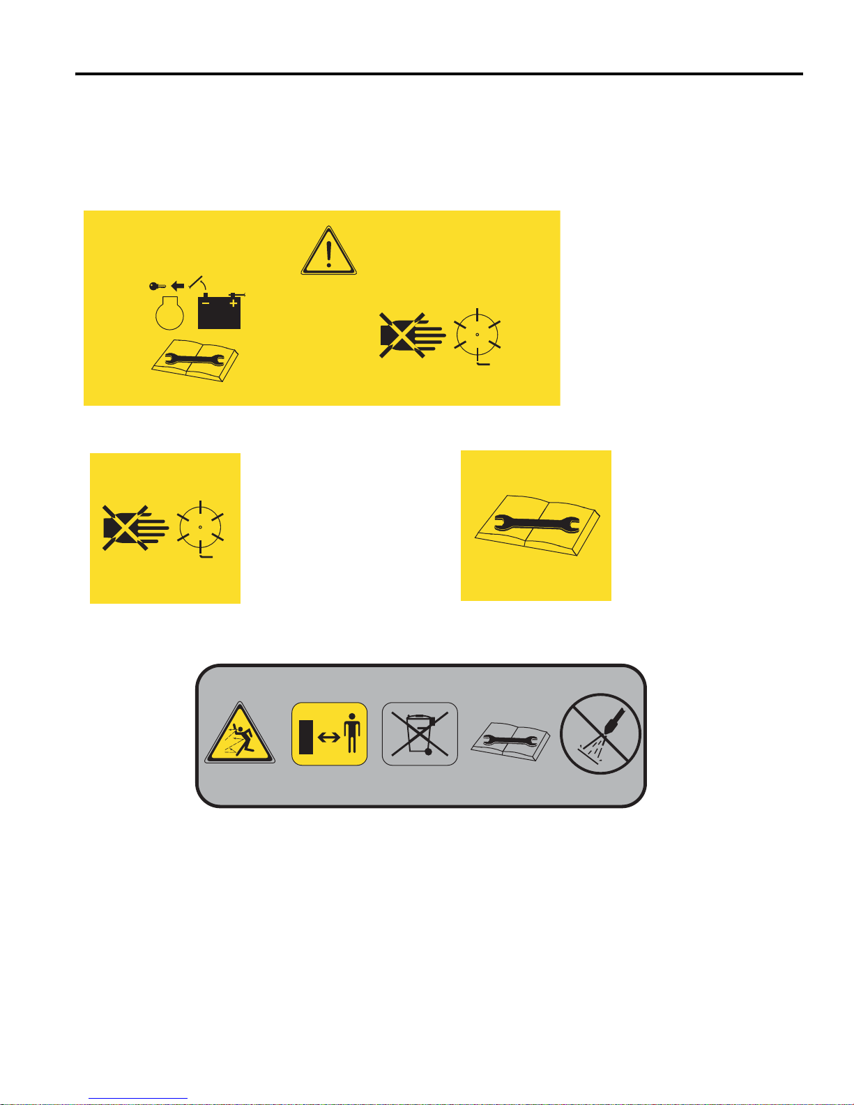
To prevent injury, disengage all
drives, engage parking brake, turn
off key switch and disconnect
power connector before working on
machine or emptying grass
catchers.
DANGER
Keep hands and feet
away from the cutting
unit to prevent serious
injury.
DANGER
1. Keep a safe distance from the machine. Keep
bystanders away.
2. Properly dispose of components from this
machine. Refer to local regulations for waste
disposal and recycling.
3. Refer to the manual for maintenance and
service procedures.
4. Do not spray water at electrical connectors,
motors or controllers. Do not use high pressure
when to clean mower.
4170321
Read the manual before
adjusting engine throttle
lever.
3 DECALS
3.1 DECALS _________________________________________________________________
Familiarize yourself with the following decals. They are critical to the safe operation of the
mower. REPLACE DAMAGED DECALS IMMEDIATELY.
13
Page 14
3 DECALS
4172240
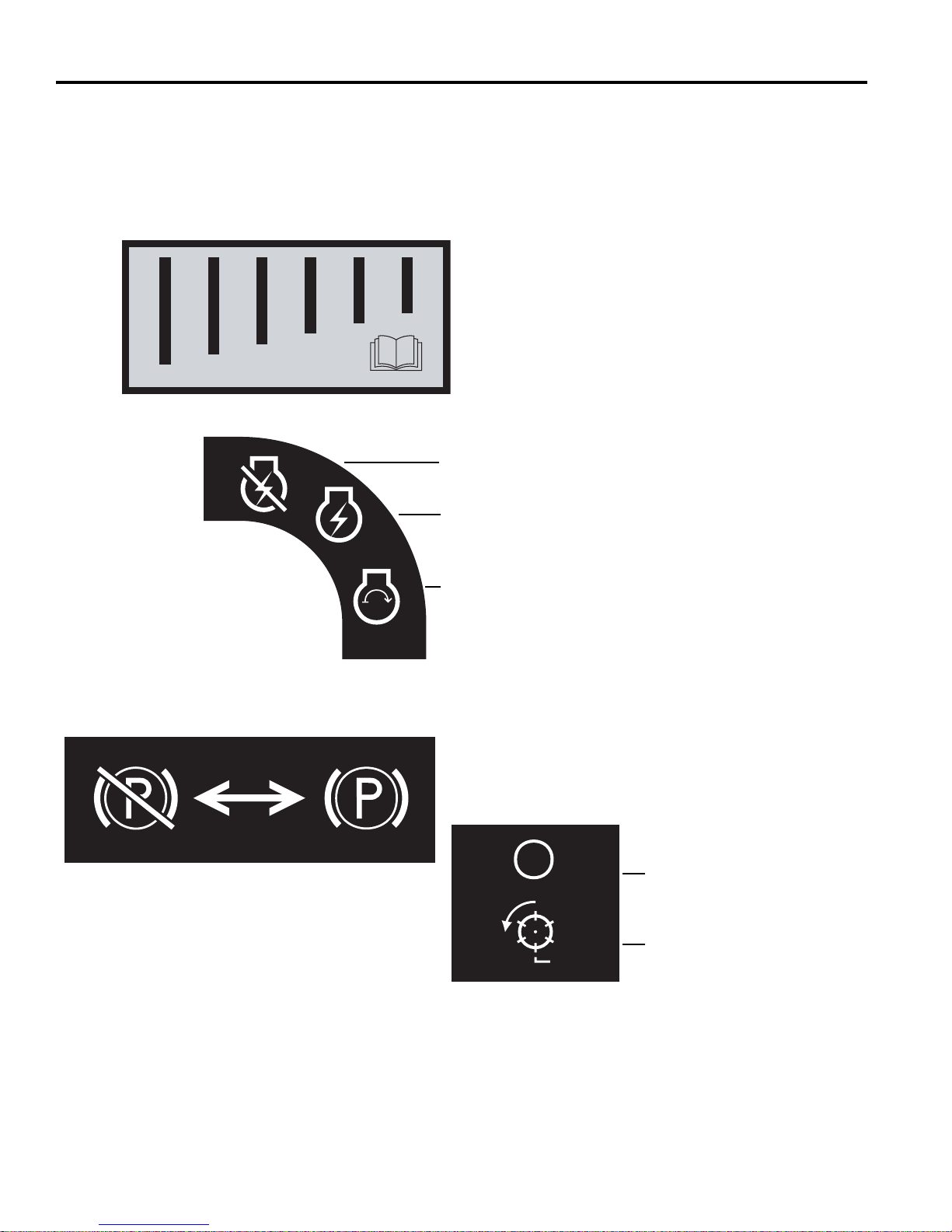
Read the manual before adjusting
front roller weight.
Disengaged Parking Engaged
Brake
Reel Switch
OFF
On
4265172
Key Switch
Off Position
Run Position
Energize Unit
Familiarize yourself with the following decals. They are critical to the safe operation of the
mower. REPLACE DAMAGED DECALS IMMEDIATELY.
4265170
4265171
14
Page 15
DECALS 3
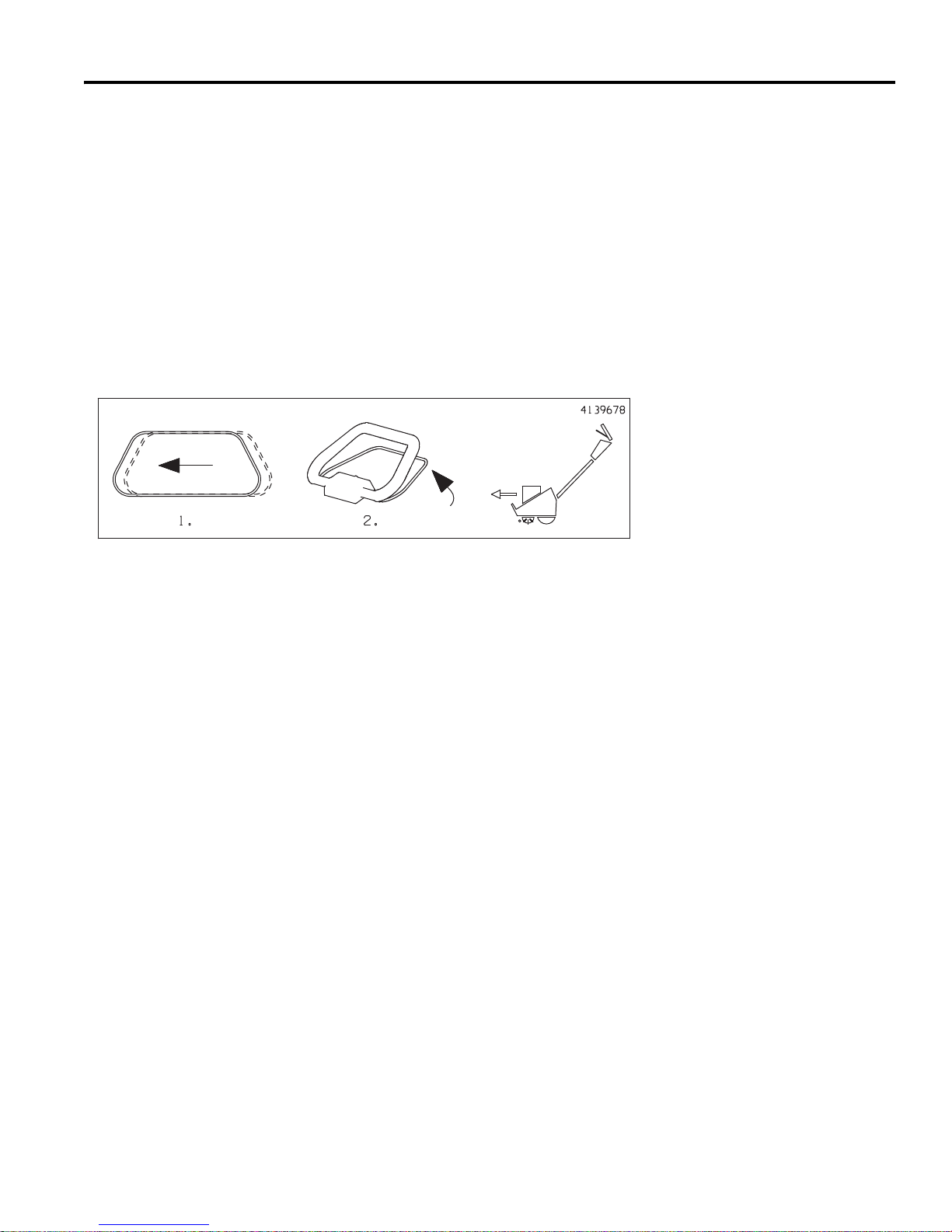
To Engage Traction.
1. Slide bail to the left.
2. Squeeze bail to handle.
15
Page 16
4 CONTROLS
Engaged Disengaged
Parking Brake
O.P.C. Traction
Drive
Squeeze bail to handle
Power On
Fast Slow
Throttle
Power Up
Slide Bail Left
Power Off
!
!
A
B
C
D
E
F
G
!
4 CONTROLS
4.1 ICONS ___________________________________________________________________
WARNING
Never attempt to operate the machine unless you have read the Safety and Operation
Manual, the Parts and Maintenance Manual and know how to operate all controls correctly.
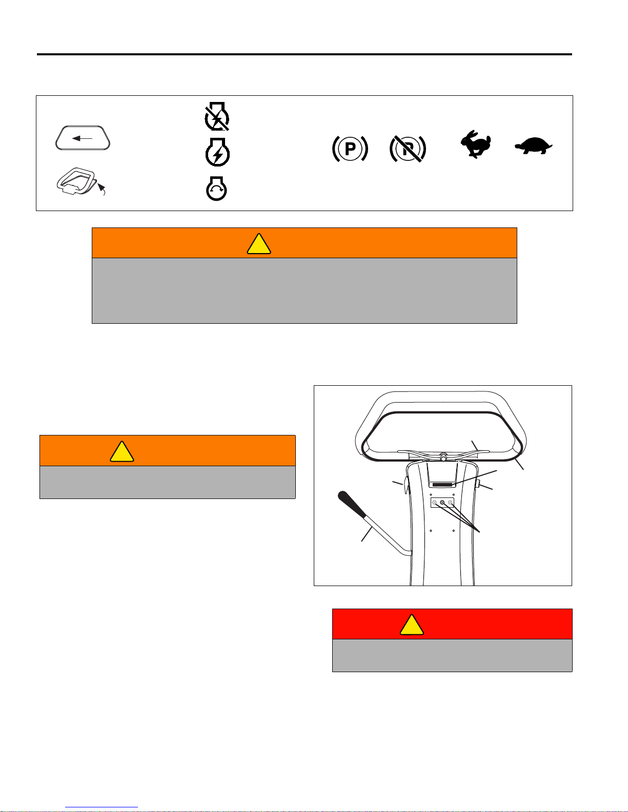
Familiarize yourself with the icons shown above and what they represent. Learn the
location and purpose of all the controls before operating this mower.
4.2 HANDLE CONTROLS ______________________________________________________
A. Parking Brake – Used whenever the mower is left
unattended or as a service brake while transporting.
Always use transport tires when transporting up or
down hills.
WARNING
To prevent injury, always use transport tires when
transporting unit up or down hills.
B. Speed Paddle – Sets maximum traction drive speed
when O.P.C. Bail is engaged. Push (+) side of lever
to increase speed. Push (-) side of lever to decrease
speed.
C. O.P.C. Bail – Slide bail slightly to the left and
squeeze bail to start traction motor. Traction motor
speed is increased as the bail moves towards the
handle. Release bail to stop unit.
D. Key Switch - The power switch turns the power on
and off. It has three positions OFF, RUN, and
START. Key switch must be in RUN position to start
units equipped with Gen-Set power module.
DANGER
Keep hands and feet away from the cutting unit to
prevent serious injury.
Figure 4A
E. Reel Switch - The reel switch is used to start and
stop the reel.
F. LCD Controls - Used to navigate through menus.
G. LCD Display - Used to display operating conditions.
16
Page 17
CONTROLS 4
G
J
K
L
!
4.3 LCD DISPLAY _____________________________________________________________
The LCD displays current functional values for the
operation of the Eclipse mower and sounds one of three
types of audible alerts. The LCD operates in one of two
modes, Operator Mode (Default), and Maintenance
Mode. Use of Maintenance mode requires a four digit pin
number.
Press either of the orange buttons (K or L) to change
screen display or change values. Push the right orange
button (K) to go forward in the display list or increase
setting value, and push the left orange button (L) to go
back in the display list or decrease setting value. The
black button (J) is used to select, reset, or change values.
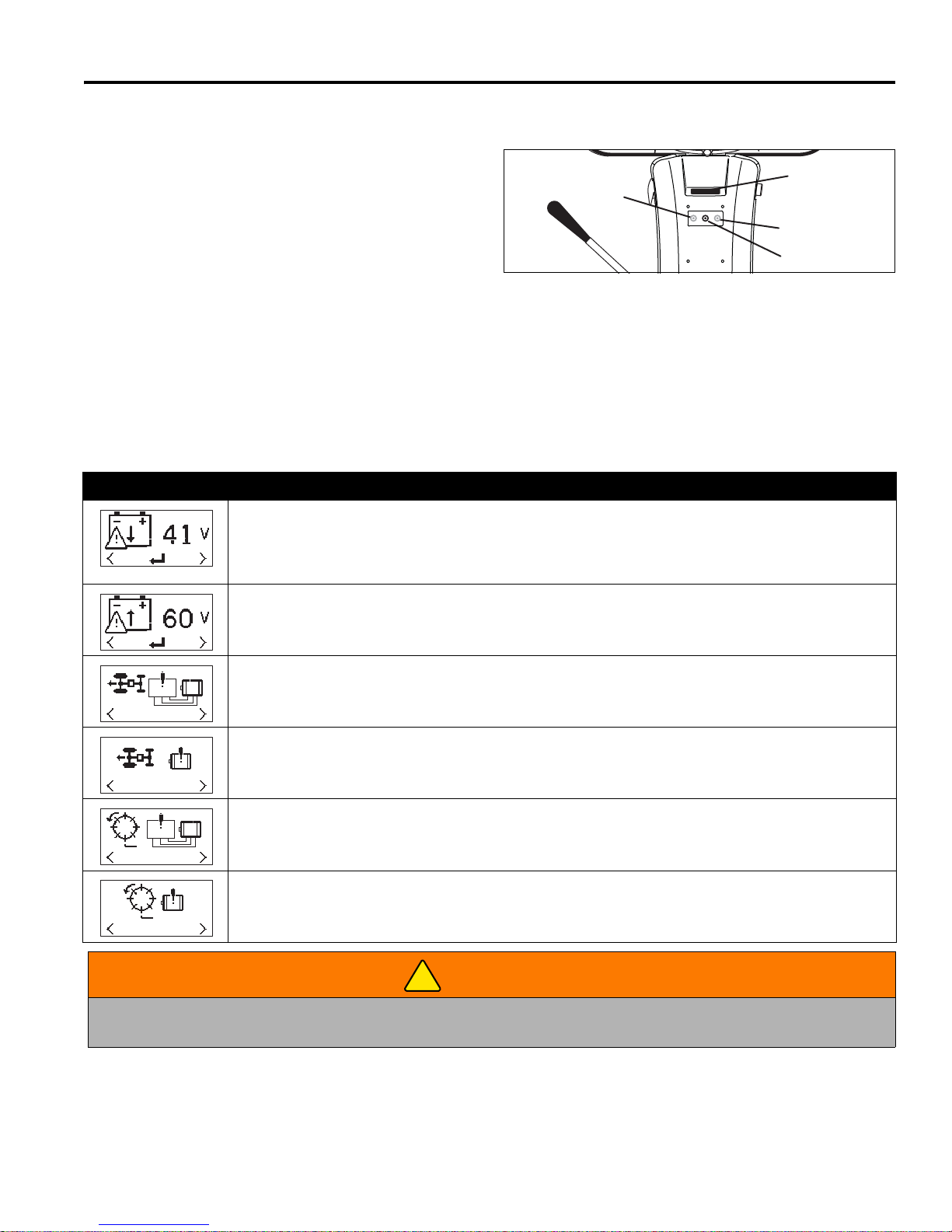
Alert Displays: In addition to the standard displays for each mode, there are six displays that are used to alert the
operator/mechanic of a problem the needs to be corrected.
Alert Display Alert Description
Low Voltage display is shown when system voltage drops below 42 Volts DC on Battery
powered mowers or 38 Volts DC on Gen-Set powered mowers, for 30 seconds and a solid tone
alarm will sound. Press the black button (J) to silence the alarm. Return mower to storage area
or install a fully charged battery pack. Reel motor will not operate with low voltage on the display.
Overvoltage/Check Voltage display is shown when system voltage is above 60 Volts DC and a
fast (2 per second) beeping alarm will sound. If not corrected, controller will shut down after 60
seconds. Check generator output before restarting system. [See Section 10.4].
Traction Motor Controller Fault display is shown when a problem is detected in the traction
motor controller. Traction motor will not operate until the problem is resolved. Return mower to
maintenance area for repair.
Audible Alerts indicate one of three conditions detected
by the LCD Display and a corresponding message would
show on the display. A solid tone indicates low system
voltage. A fast beeping (2 per second) alert indicates an
over voltage condition. A slow beeping (1 every 3
seconds) alert indicates mower is in backlap mode.
Figure 4B
Traction Motor Fault display is shown when a traction motor short circuit is detected or the
traction motor current draw exceeds 30 Amps for one second. Traction motor will not operate
until the problem is resolved. Return mower to maintenance area for repair.
Reel Motor Controller Fault display is shown when a problem is detected in the reel motor
controller. Reel motor will not operate until the problem is resolved. Return mower to
maintenance area for repair.
Reel Motor Fault display is shown when a reel motor short circuit is detected or the reel motor
current draw exceeds 30 Amps for one second. Reel motor will not operate until the problem is
resolved. Return mower to maintenance area for repair.
WARNING
Turn reel switch off, release bail, turn key to off position, and disconnect battery connector before checking for
obstructions in reel.
17
Page 18
4 CONTROLS
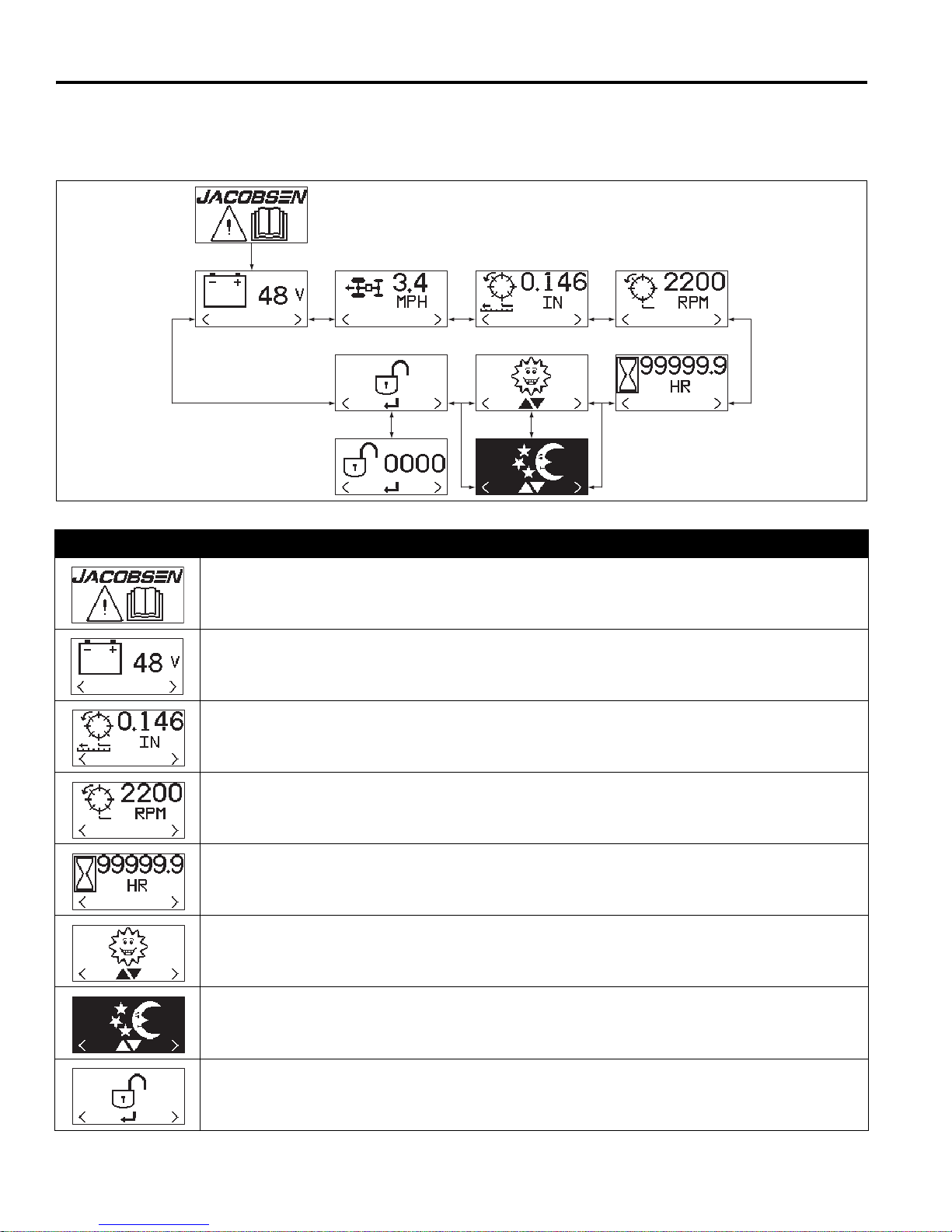
Operator Mode is used by the operator for system voltage information, travel speed, FOC setting, reel speed, and total
hours on mower. Press the orange buttons (K and L) on the front handle cover to toggle between the different displays.
Operator Mode is view only, only screen illumination mode can be changed.
Display Description
Start-Up Screen - Displays for up to five seconds when system is started.
System Voltage - Displays system voltage between 42 and 59 volts. Screen will be replaced
with alert screen when system voltage drops below 42 volts or rises above 60 volts.
FOC Setting - Displays FOC (Frequency of Clip) setting. When FOC is set to 0, reel will operate
at the fixed reel speed.
Fixed Reel Speed - Displays fixed reel speed setting with FOC set to 0. Fixed reel speed setting
is not used for any FOC other than 0.
Hour Meter - Displays total hours unit has been operated.
Daytime Illumination - When selected, LCD displays dark pixels on a light background. Press
the black button (J) to toggle between daytime and nighttime illumination.
Nighttime Illumination - When selected, LCD displays light pixels on a dark background. Press
the black button (J) to toggle between daytime and nighttime illumination.
Maintenance Mode PIN - Used to enter Maintenance Mode. Maintenance Mode pin is required.
See Maintenance Mode.
18
Page 19
CONTROLS 4
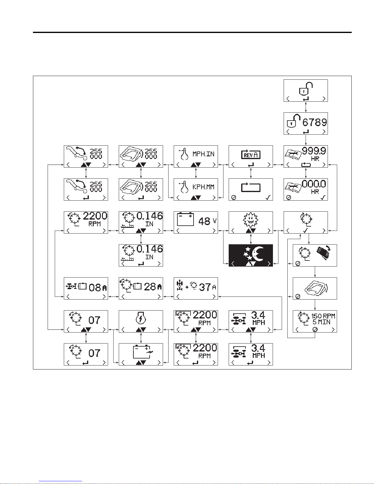
Maintenance Mode is used to set and adjust all functional values for the Eclipse Mower. LCD displays available in
Maintenance Mode are, maintenance hours, backlap, system voltage, travel speed, set FOC, reel speed, traction motor
current draw, reel motor current draw, total motor current draw, set mow speed, set reel speed, set power source, set
number of reel blades, calibrate speed paddle, calibrate bail lever, set display units, and factory reset.
See Operator Mode for descriptions of Daytime/Nighttime
Illumination, System Voltage, and Fixed Reel Speed
screens.
Figure 4C
19
Page 20
4 CONTROLS
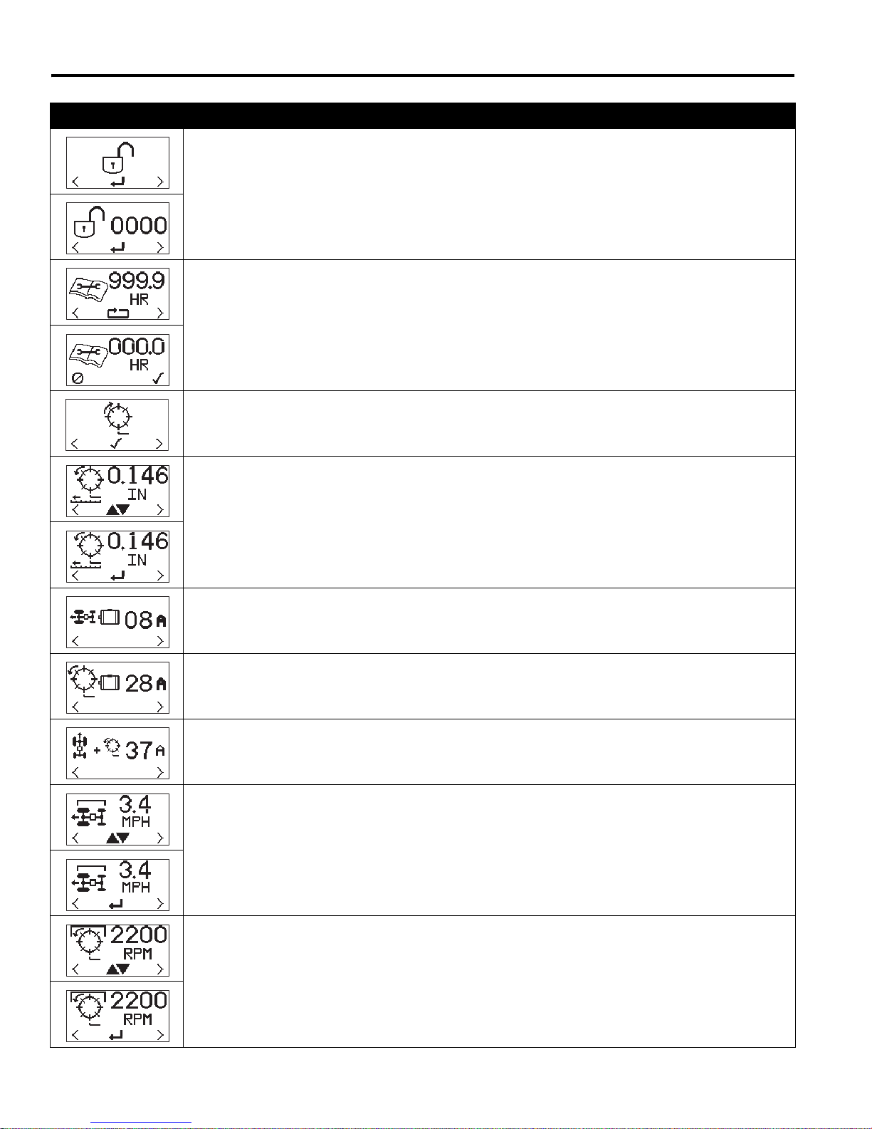
Display Description
To enter Maintenance Mode, press either orange buttons (K or L) until Maintenance Mode PIN
screen is on the display and press black button (J). Use the orange buttons (K or L) to select and
the black button (J) to enter the digits for the Mechanic Mode pin.
NOTE: The default PIN for Maintenance Mode is 6789. The Maintenance Mode PIN can be
customized to a setting of your choice. Please contact your Jacobsen Dealer or Jacobsen
Technical Support (1800-848-1636 Option 2) for complete instructions.
Maintenance Hours - System can track up to 999.9 hours for maintenance purposes.
To reset maintenance hours, press either of the orange buttons (K or L) on the front cover until
the maintenance hours screen is on the LCD display. Press the black button (J) to move to the
confirm reset screen. Press the right orange button (K) to confirm reset, or press left orange
button (L) to cancel reset.
Backlap Select - Used to switch mower to backlap mode. See Section 11.4 for backlap screen
descriptions.
Set FOC - To set the fixed FOC, press either of the orange buttons (K or L) on the front cover
until the FOC set screen is on the LCD display. Press the black button (J) to enter set mode. Use
the orange buttons to raise (K) or lower (L) the FOC value to the desired setting. press the black
button to set speed.
Fixed FOC setting must be 0 or between 0.087 and 0.178 in. (2.2 and 4.5 mm). [See Section
4.4].
Traction Motor Current - Displays current draw of traction drum motor. Fault will be displayed if
current draw is greater than 30 Amps for one second.
Reel Motor Current - Displays current draw of reel motor. Fault will be displayed if current draw
is greater than 30 Amps for one second.
Total Motor Current - Displays total current draw of traction drum motor and reel motor.
Maximum Mow Speed - To set the maximum mow speed, press either of the orange buttons (K
or L) on the front cover until the set max mow speed screen is on the LCD display. Press the
black button (J) to enter set mode. Use the orange buttons to raise (K) or lower (L) the maximum
mow speed to the desired speed. press the black button to set speed.
Maximum mow speed must be between 2.0 and 3.8 MPH (3.2 and 6.1 kph).
Fixed Reel Speed: To set the fixed reel speed, the FOC setting must be set to 0, then press
either of the orange buttons (K or L) on the front cover until the set reel speed screen is on the
LCD display. Press the black button (J) to enter set mode. Use the orange buttons to raise (K) or
lower (L) the reel speed to the desired setting.
Fixed reel speed must be set between 1800 and 2200 rpm.
The Maximum Mow Speed and the Fixed Reel Speed are used to determine the FOC
(Frequency of Cut) [See Section 4.4].
20
Page 21
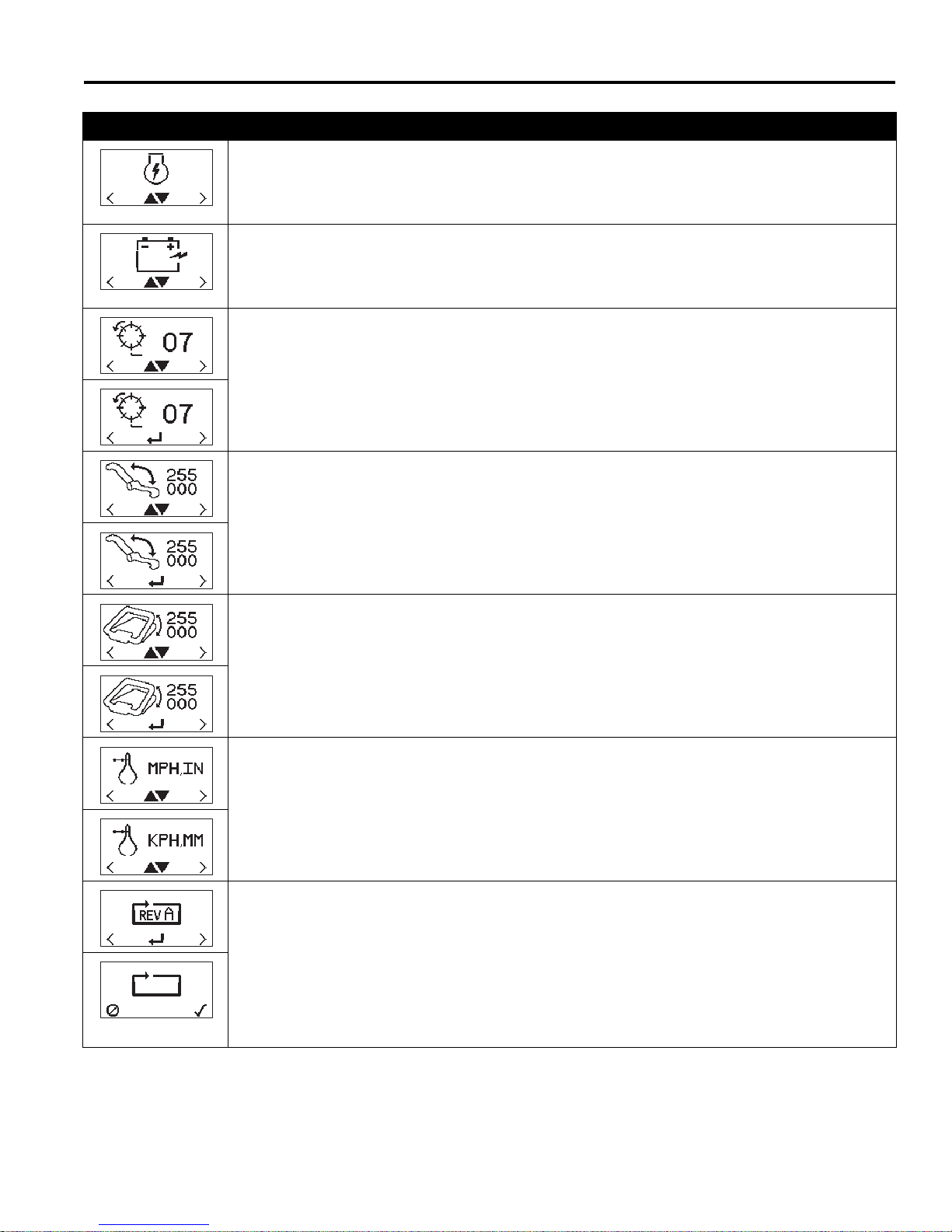
Display Description
Gen-Set Power Module - Used to indicate the gen-set power module is installed on the mower.
This setting is used by system controllers and does not affect operation of mower. Do not
operate mower with incorrect power module setting. Press the black button (J) to toggle
between the power module settings.
Battery Power Module - Used to indicate the battery power module is installed on the mower.
This setting is used by system controllers and does not affect operation of mower. Do not
operate mower with incorrect power module setting. Press the black button (J) to toggle
between the power module settings.
Set Number of Reel Blades: To set the number of reel blades, press either of the orange buttons
(K or L) on the front cover until the reel blades screen is on the LCD display. Press the black
button (J) to enter set mode. Use the orange buttons to set the number of blades.
Available reel blades are 7, 9 (Floating Only), 11 or 15.
Speed Paddle Calibration - Before calibrating the speed paddle, check that paddle stops are
properly adjusted [See Section 6.3].To calibrate the paddle, press either of the orange buttons
(K or L) on the front cover until the speed paddle calibration screen is on the LCD display. Press
the black button (J) to enter set mode. Move the speed paddle through its entire range of
movement to determine minimum and maximum values.
Values displayed will change as controls are moved.
CONTROLS 4
Bail Lever Calibration - To calibrate the bail lever, press either of the orange buttons (K or L) on
the front cover until the bail lever calibration screen is on the LCD display. Press the black button
(J) to enter set mode. Fully engage and disengage the bail lever to determine minimum and
maximum values.
Values displayed will change as controls are moved.
Display Units - To set the display units, press either of the orange buttons (K or L) on the front
cover until the units screen is on the LCD display. Press the black button (J) to toggle between
english (MPH, IN) or metric (KPH, mm) units.
Factory Reset - To reset controller to factory default values, press either of the orange buttons (K
or L) on the front cover until the Factory Reset screen is on the LCD display. Press the black
button (J) to move to the confirm reset screen. Press the right orange button (K) to confirm reset,
or press left orange button (L) to cancel reset.
Maximum Mow Speed......3.4 Mph (5.5 kph)
Reel Speed ......................2200 rpm
Fixed FOC Setting............0.146
Display units.....................English
21
Page 22

4 CONTROLS
4.4 FREQUENCY OF CUT ______________________________________________________
The FOC (Frequency of cut) is the distance, in inches
(mm), the machine travels forward between reel blades
contacting the bedknife. The FOC can be adjusted either
by changing the Fixed FOC setting or by changing the
maximum mow speed and the fixed reel speed on the
LCD display.
Adjust FOC with Fixed FOC setting
Changing the FOC setting to a value other than 0 will
enable the fixed FOC mode and disable the reel speed
setting. As mower travel speed increases or decreases,
reel speed will automatically adjust as required to
maintain set FOC.
Adjust FOC with Reel Speed Setting
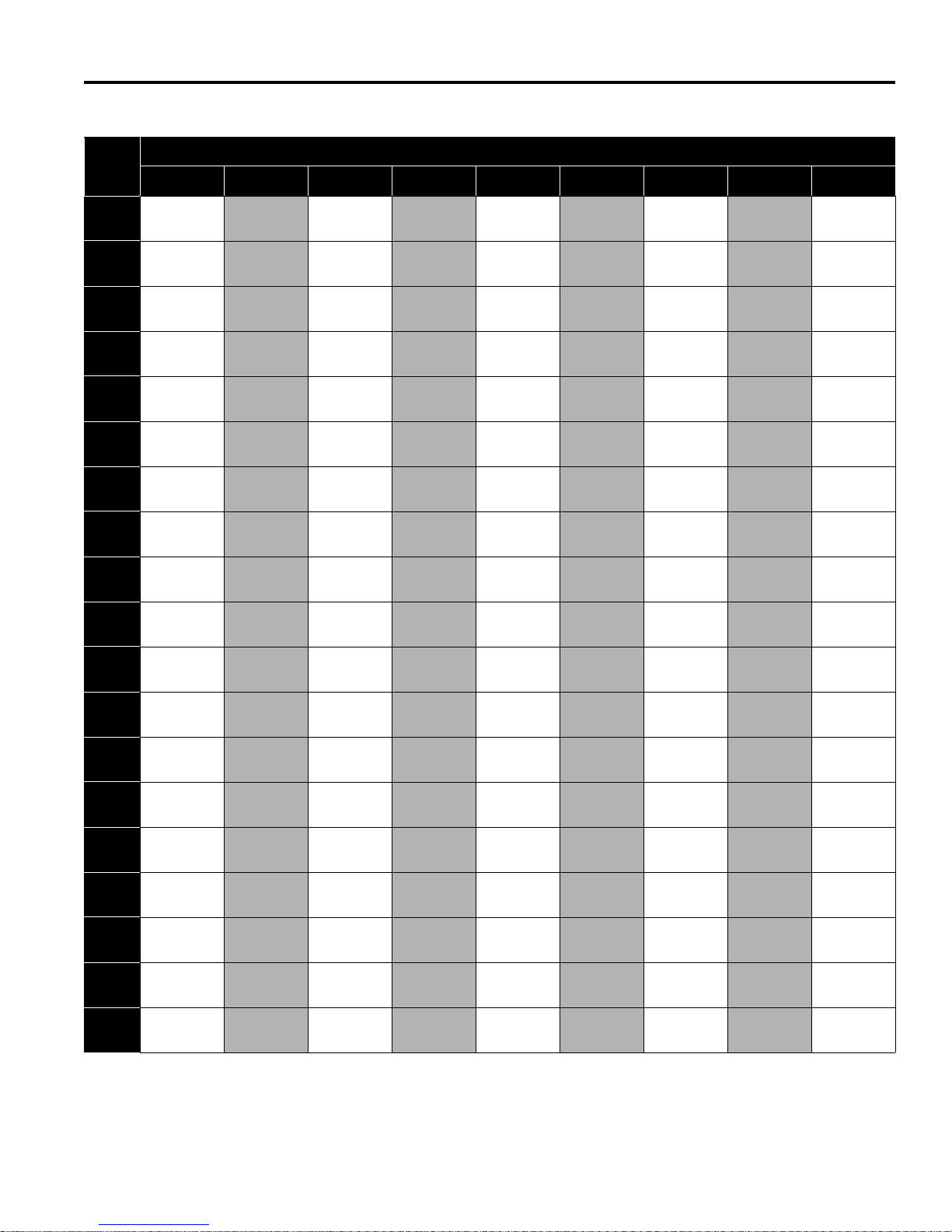
1. Using the FOC charts, determine the maximum mow
speed and fixed reel speed required for the desired
FOC.
2. Start the unit in Maintenance mode. [Section 4.3]
3. Set fixed FOC setting to 0
4. Set desired Maximum Mow Speed
5. Set desired Fixed Reel Speed
NOTE: Mow speed is measured in mph (kph), FOC is
measured in inches (millimeters).
22
Page 23
CONTROLS 4
15 Blade Reel FOC Table
Mow
Speed
2.00 0.078 0.076 0.074 0.072 0.070 0.069 0.067 0.065 0.064
(3.22) (1.987) (1.933) (1.882) (1.834) (1.788) (1.745) (1.703) (1.663) (1.626)
2.10 0.082 0.080 0.078 0.076 0.074 0.072 0.070 0.069 0.067
(3.38) (2.086) (2.030) (1.976) (1.926) (1.878) (1.832) (1.788) (1.747) (1.707)
2.20 0.086 0.084 0.082 0.079 0.077 0.076 0.074 0.072 0.070
(3.54) (2.186) (2.126) (2.071) (2.017) (1.967) (1.919) (1.873) (1.830) (1.788)
2.30 0.090 0.088 0.085 0.083 0.081 0.079 0.077 0.075 0.074
(3.70) (2.285) (2.223) (2.165) (2.109) (2.056) (2.006) (1.958) (1.913) (1.869)
2.40 0.094 0.091 0.089 0.087 0.084 0.082 0.080 0.079 0.077
(3.86) (2.384) (2.320) (2.259) (2.201) (2.146) (2.093) (2.044) (1.996) (1.951)
2.50 0.098 0.095 0.093 0.090 0.088 0.086 0.084 0.082 0.080
(4.02) (2.484) (2.416) (2.353) (2.293) (2.235) (2.181) (2.129) (2.079) (2.032)
2.60 0.102 0.099 0.096 0.094 0.092 0.089 0.087 0.085 0.083
(4.18) (2.583) (2.513) (2.447) (2.384) (2.325) (2.268) (2.214) (2.162) (2.113)
2.70 0.106 0.103 0.100 0.097 0.095 0.093 0.091 0.088 0.086
(4.35) (2.682) (2.610) (2.541) (2.476) (2.414) (2.355) (2.299) (2.246) (2.195)
2.80 0.110 0.107 0.104 0.101 0.099 0.096 0.094 0.092 0.090
(4.51) (2.782) (2.706) (2.635) (2.568) (2.503) (2.442) (2.384) (2.329) (2.276)
2.90 0.113 0.110 0.107 0.105 0.102 0.100 0.097 0.095 0.093
(4.67) (2.881) (2.803) (2.729) (2.659) (2.593) (2.530) (2.469) (2.412) (2.357)
3.00 0.117 0.114 0.111 0.108 0.106 0.103 0.101 0.098 0.096
(4.83) (2.980) (2.900) (2.823) (2.751) (2.682) (2.617) (2.555) (2.495) (2.438)
3.10 0.121 0.118 0.115 0.112 0.109 0.106 0.104 0.102 0.099
(4.99) (3.080) (2.996) (2.918) (2.843) (2.772) (2.704) (2.640) (2.578) (2.520)
3.20 0.125 0.122 0.119 0.116 0.113 0.110 0.107 0.105 0.102
(5.15) (3.179) (3.093) (3.012) (2.934) (2.861) (2.791) (2.725) (2.661) (2.601)
3.30 0.129 0.126 0.122 0.119 0.116 0.113 0.111 0.108 0.106
(5.31) (3.278) (3.190) (3.106) (3.026) (2.950) (2.879) (2.810) (2.745) (2.682)
3.40 0.133 0.129 0.126 0.123 0.120 0.117 0.114 0.111 0.109
(5.47) (3.378) (3.286) (3.200) (3.118) (3.040) (2.966) (2.895) (2.828) (2.764)
3.50 0.137 0.133 0.130 0.126 0.123 0.120 0.117 0.115 0.112
(5.63) (3.477) (3.383) (3.294) (3.210) (3.129) (3.053) (2.980) (2.911) (2.845)
3.60 0.141 0.137 0.133 0.130 0.127 0.124 0.121 0.118 0.115
(5.79) (3.576) (3.480) (3.388) (3.301) (3.219) (3.140) (3.065) (2.994) (2.926)
3.70 0.145 0.141 0.137 0.134 0.130 0.127 0.124 0.121 0.118
(5.95) (3.676) (3.576) (3.482) (3.393) (3.308) (3.227) (3.151) (3.077) (3.007)
3.80 0.149 0.145 0.141 0.137 0.134 0.130 0.127 0.124 0.122
(6.12) (3.775) (3.673) (3.576) (3.485) (3.398) (3.315) (3.236) (3.160) (3.089)
1800 1850 1900 1950 2000 2050 2100 2150 2200
, Product No 63339, 63341, 63335, 63337, 63348, 63350, 63344, 63346 (Standard Reel)
Reel RPM
23
Page 24
4 CONTROLS
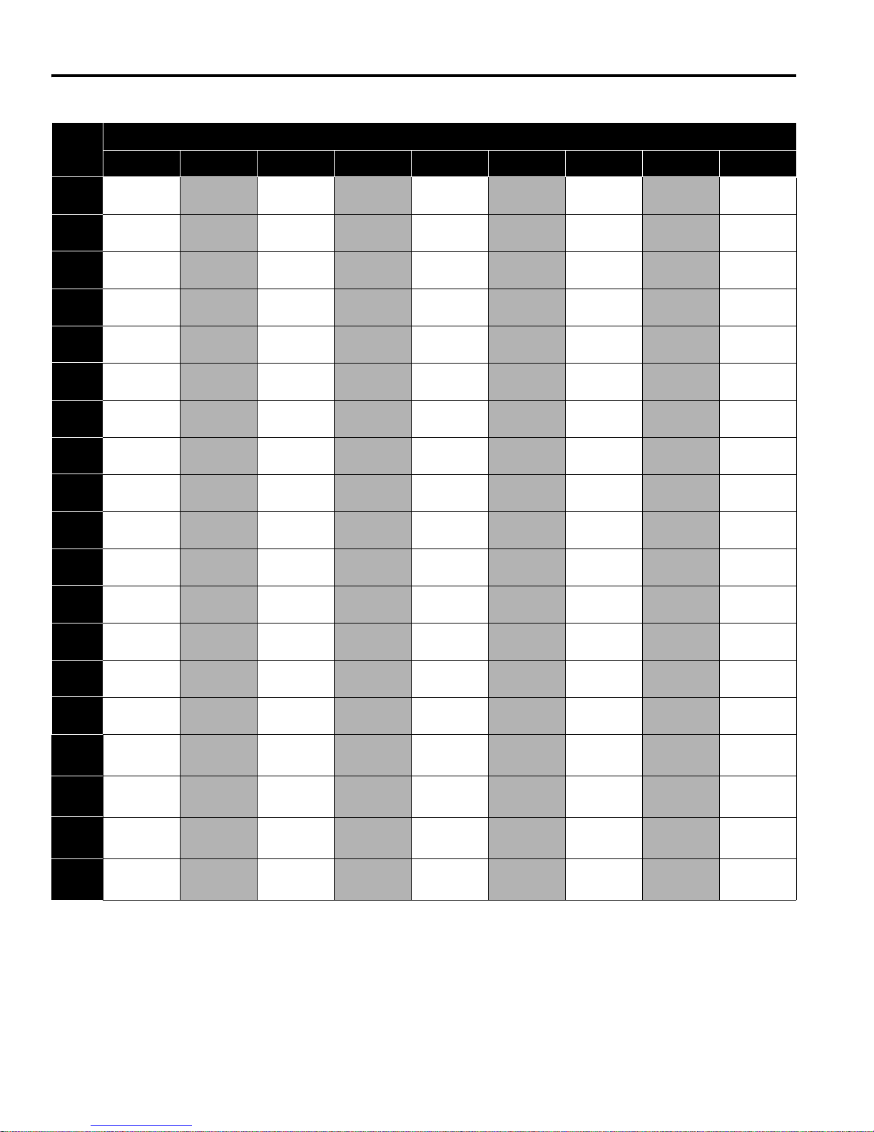
11 Blade Reel FOC Table, Product No. 63334, 63336, 63338, 63340, 63347, 63349, 63343, 63345 (Standard Reel)
Mow
Speed
2.0
(3.22)
2.1
(3.38)
2.2
(3.54)
2.3
(3.7)
2.4
(3.86)
2.5
(4.02)
2.6
(4.18)
2.7
(4.35)
2.8
(4.51)
2.9
(4.67)
3.0
(4.83)
3.1
(4.99)
3.2
(5.15)
3.3
(5.31)
3.4
(5.47)
3.50 0.187 0.182 0.177 0.172 0.168 0.164 0.160 0.156 0.153
(5.63) (4.741) (4.613) (4.492) (4.377) (4.267) (4.163) (4.064) (3.969) (3.879)
3.60 0.192 0.187 0.182 0.177 0.173 0.169 0.165 0.161 0.157
(5.79) (4.877) (4.745) (4.620) (4.502) (4.389) (4.282) (4.180) (4.083) (3.990)
3.70 0.197 0.192 0.187 0.182 0.178 0.173 0.169 0.165 0.161
(5.95) (5.012) (4.877) (4.748) (4.627) (4.511) (4.401) (4.296) (4.196) (4.101)
3.80 0.203 0.197 0.192 0.187 0.182 0.178 0.174 0.170 0.166
(6.12) (5.148) (5.009) (4.877) (4.752) (4.633) (4.520) (4.412) (4.310) (4.212)
1800 1850 1900 1950 2000 2050 2100 2150 2200
0.107
(2.709)
0.112
(2.845)
0.117
(2.98)
0.123
(3.116)
0.128
(3.251)
0.133
(3.387)
0.139
(3.522)
0.144
(3.658)
0.149
(3.793)
0.155
(3.929)
0.160
(4.064)
0.165
(4.199)
0.171
(4.335)
0.176
(4.47)
0.181
(4.606)
0.104
(2.636)
0.109
(2.768)
0.114
(2.9)
0.119
(3.032)
0.125
(3.163)
0.130
(3.295)
0.135
(3.427)
0.140
(3.559)
0.145
(3.691)
0.150
(3.822)
0.156
(3.954)
0.161
(4.086)
0.166
(4.218)
0.171
(4.35)
0.176
(4.481)
0.101
(2.567)
0.106
(2.695)
0.111
(2.823)
0.116
(2.952)
0.121
(3.08)
0.126
(3.208)
0.131
(3.337)
0.136
(3.465)
0.141
(3.593)
0.147
(3.722)
0.152
(3.85)
0.157
(3.978)
0.162
(4.107)
0.167
(4.235)
0.172
(4.363)
0.098
(2.501)
0.103
(2.626)
0.108
(2.751)
0.113
(2.876)
0.118
(3.001)
0.123
(3.126)
0.128
(3.251)
0.133
(3.376)
0.138
(3.501)
0.143
(3.626)
0.148
(3.751)
0.153
(3.876)
0.158
(4.001)
0.162
(4.127)
0.167
(4.252)
Reel RPM
0.096
(2.438)
0.101
(2.56)
0.106
(2.682)
0.110
(2.804)
0.115
(2.926)
0.120
(3.048)
0.125
(3.17)
0.130
(3.292)
0.134
(3.414)
0.139
(3.536)
0.144
(3.658)
0.149
(3.78)
0.154
(3.901)
0.158
(4.023)
0.163
(4.145)
0.094
(2.379)
0.098
(2.498)
0.103
(2.617)
0.108
(2.736)
0.112
(2.855)
0.117
(2.974)
0.122
(3.093)
0.126
(3.212)
0.131
(3.33)
0.136
(3.449)
0.140
(3.568)
0.145
(3.687)
0.150
(3.806)
0.155
(3.925)
0.159
(4.044)
0.091
(2.322)
0.096
(2.438)
0.101
(2.555)
0.105
(2.671)
0.110
(2.787)
0.114
(2.903)
0.119
(3.019)
0.123
(3.135)
0.128
(3.251)
0.133
(3.367)
0.137
(3.483)
0.142
(3.6)
0.146
(3.716)
0.151
(3.832)
0.155
(3.948)
0.089
(2.268)
0.094
(2.382)
0.098
(2.495)
0.103
(2.609)
0.107
(2.722)
0.112
(2.835)
0.116
(2.949)
0.121
(3.062)
0.125
(3.176)
0.129
(3.289)
0.134
(3.402)
0.138
(3.516)
0.143
(3.629)
0.147
(3.743)
0.152
(3.856)
0.087
(2.217)
0.092
(2.328)
0.096
(2.438)
0.100
(2.549)
0.105
(2.66)
0.109
(2.771)
0.113
(2.882)
0.118
(2.993)
0.122
(3.103)
0.127
(3.214)
0.131
(3.325)
0.135
(3.436)
0.140
(3.547)
0.144
(3.658)
0.148
(3.768)
24
Page 25
CONTROLS 4
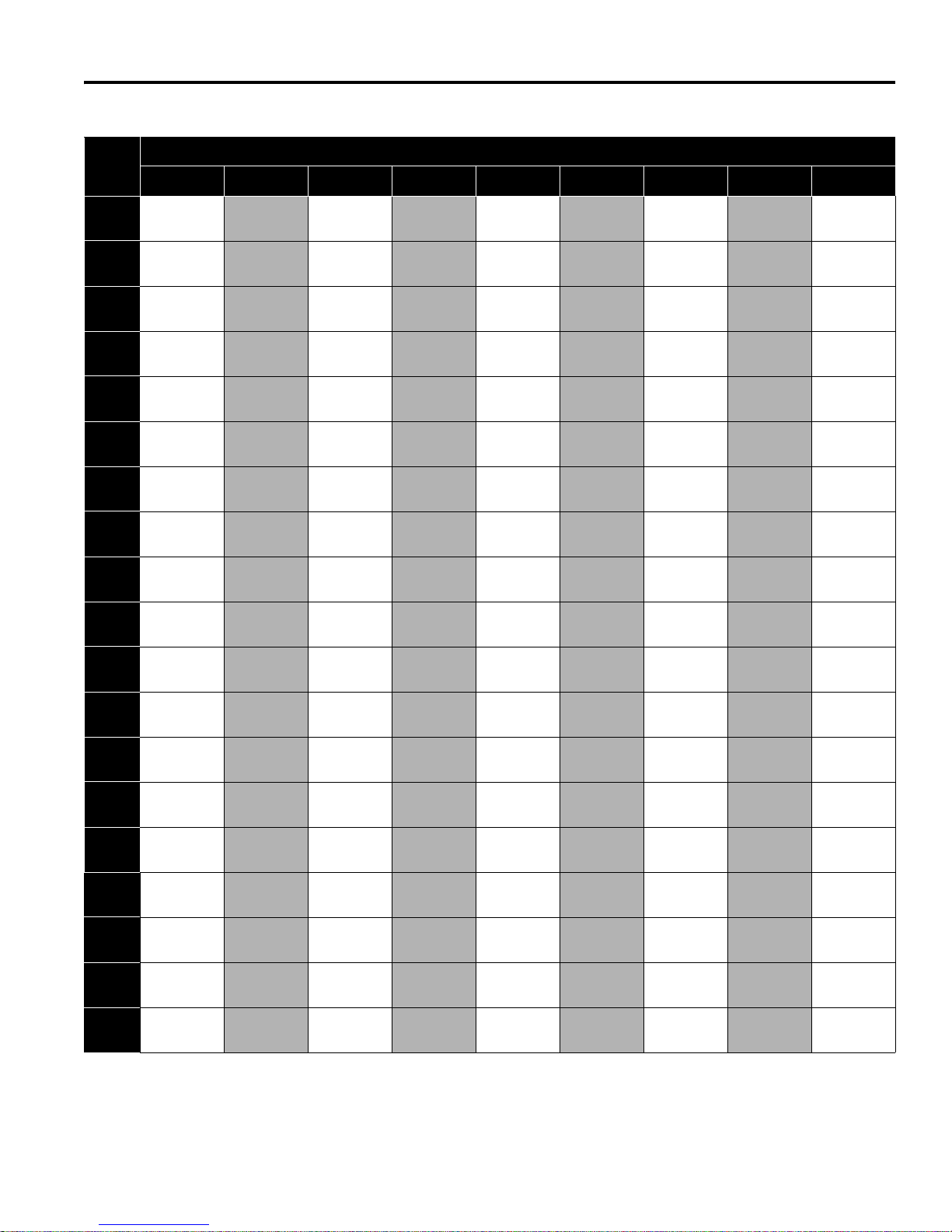
9 Blade Reel FOC Table, Product No. 63340, 63349 (Optional Reel)
Mow
Speed
2.0 0.130 0.127 0.124 0.120 0.117 0.114 0.112 0.109 0.107
(3.22) (3.311) (3.222) (3.137) (3.057) (2.98) (2.908) (2.838) (2.772) (2.709)
2.1 0.137 0.133 0.130 0.126 0.123 0.120 0.117 0.115 0.112
(3.38) (3.477) (3.383) (3.294) (3.21) (3.129) (3.053) (2.98) (2.911)
2.2 0.143 0.140 0.136 0.132 0.129 0.126 0.123 0.120 0.117
(3.54) (3.643) (3.544) (3.451) (3.362) (3.278) (3.198) (3.122) (3.05) (2.98)
2.3 0.150 0.146 0.142 0.138 0.135 0.132 0.129 0.126 0.123
(3.7) (3.808) (3.705) (3.608) (3.515) (3.427) (3.344) (3.264) (3.188) (3.116)
2.4 0.156 0.152 0.148 0.144 0.141 0.137 0.134 0.131 0.128
(3.86) (3.974) (3.866) (3.765) (3.668) (3.576) (3.489) (3.406) (3.327) (3.251)
2.5 0.163 0.159 0.154 0.150 0.147 0.143 0.140 0.136 0.133
(4.02) (4.139) (4.027) (3.921) (3.821) (3.725) (3.634) (3.548) (3.465) (3.387)
2.6 0.169 0.165 0.161 0.156 0.153 0.149 0.145 0.142 0.139
(4.18) (4.305) (4.188) (4.078) (3.974) (3.874) (3.78) (3.69) (3.604) (3.522)
2.7 0.176 0.171 0.167 0.162 0.158 0.155 0.151 0.147 0.144
(4.35) (4.47) (4.35) (4.235) (4.127) (4.023) (3.925) (3.832) (3.743) (3.658)
2.8 0.183 0.178 0.173 0.168 0.164 0.160 0.156 0.153 0.149
(4.51) (4.636) (4.511) (4.392) (4.279) (4.172) (4.071) (3.974) (3.881) (3.793)
2.9 0.189 0.184 0.179 0.174 0.170 0.166 0.162 0.158 0.155
(4.67) (4.802) (4.672) (4.549) (4.432) (4.321) (4.216) (4.116) (4.02) (3.929)
3.0 0.196 0.190 0.185 0.181 0.176 0.172 0.168 0.164 0.160
(4.83) (4.967) (4.833) (4.706) (4.585) (4.47) (4.361) (4.258) (4.159) (4.064)
3.1 0.202 0.197 0.191 0.187 0.182 0.177 0.173 0.169 0.165
(4.99) (5.133) (4.994) (4.863) (4.738) (4.619) (4.507) (4.399) (4.297) (4.199)
3.2 0.209 0.203 0.198 0.193 0.188 0.183 0.179 0.175 0.171
(5.15) (5.298) (5.155) (5.019) (4.891) (4.768) (4.652) (4.541) (4.436) (4.335)
3.3 0.215 0.209 0.204 0.199 0.194 0.189 0.184 0.180 0.176
(5.31) (5.464) (5.316) (5.176) (5.044) (4.917) (4.798) (4.683) (4.574) (4.47)
3.4 0.222 0.216 0.210 0.205 0.199 0.195 0.190 0.186 0.181
(5.47) (5.629) (5.477) (5.333) (5.196) (5.066) (4.943) (4.825) (4.713) (4.606)
3.50 0.228 0.222 0.216 0.211 0.205 0.200 0.196 0.191 0.187
(5.63) (5.795) (5.638) (5.490) (5.349) (5.215) (5.088) (4.967) (4.852) (4.741)
3.60 0.235 0.228 0.222 0.217 0.211 0.206 0.201 0.196 0.192
(5.79) (5.961) (5.799) (5.647) (5.502) (5.364) (5.234) (5.109) (4.990) (4.877)
3.70 0.241 0.235 0.228 0.223 0.217 0.212 0.207 0.202 0.197
(5.95) (6.126) (5.961) (5.804) (5.655) (5.513) (5.379) (5.251) (5.129) (5.012)
3.80 0.248 0.241 0.235 0.229 0.223 0.217 0.212 0.207 0.203
(6.12) (6.292) (6.122) (5.961) (5.808) (5.663) (5.524) (5.393) (5.267) (5.148)
1800 1850 1900 1950 2000 2050 2100 2150 2200
Reel RPM
(2.845)
25
Page 26
4 CONTROLS
7 Blade Reel FOC Table, Product No. 63342, 63351 (Standard Reel) and 63340, 63349 (Optional Reel)
Mow
Speed
2.0 0.168 0.163 0.159 0.155 0.151 0.147 0.144 0.140 0.137
(3.22) (4.258) (4.142) (4.033) (3.93) (3.832) (3.738) (3.649) (3.564) (3.483)
2.1 0.176 0.171 0.167 0.162 0.158 0.155 0.151 0.147 0.144
(3.38) (4.47) (4.35) (4.235) (4.127) (4.023) (3.925) (3.832) (3.743) (3.658)
2.2 0.184 0.179 0.175 0.170 0.166 0.162 0.158 0.154 0.151
(3.54) (4.683) (4.557) (4.437) (4.323) (4.215) (4.112) (4.014) (3.921) (3.832)
2.3 0.193 0.188 0.183 0.178 0.173 0.169 0.165 0.161 0.158
(3.7) (4.896) (4.764) (4.638) (4.52) (4.407) (4.299) (4.197) (4.099) (4.006)
2.4 0.201 0.196 0.191 0.186 0.181 0.177 0.172 0.168 0.165
(3.86) (5.109) (4.971) (4.84) (4.716) (4.598) (4.486) (4.379) (4.277) (4.18)
2.5 0.210 0.204 0.198 0.193 0.189 0.184 0.180 0.175 0.171
(4.02) (5.322) (5.178) (5.042) (4.913) (4.79) (4.673) (4.562) (4.456) (4.354)
2.6 0.218 0.212 0.206 0.201 0.196 0.191 0.187 0.182 0.178
(4.18) (5.535) (5.385) (5.243) (5.109) (4.981) (4.86) (4.744) (4.634) (4.528)
2.7 0.226 0.220 0.214 0.209 0.204 0.199 0.194 0.189 0.185
(4.35) (5.748) (5.592) (5.445) (5.306) (5.173) (5.047) (4.927) (4.812) (4.703)
2.8 0.235 0.228 0.222 0.217 0.211 0.206 0.201 0.196 0.192
(4.51) (5.961) (5.799) (5.647) (5.502) (5.364) (5.234) (5.109) (4.99) (4.877)
2.9 0.243 0.236 0.230 0.224 0.219 0.213 0.208 0.203 0.199
(4.67) (6.173) (6.007) (5.848) (5.699) (5.556) (5.421) (5.291) (5.168) (5.051)
3.0 0.251 0.245 0.238 0.232 0.226 0.221 0.216 0.210 0.206
(4.83) (6.386) (6.214) (6.05) (5.895) (5.748) (5.607) (5.474) (5.347) (5.225)
3.1 0.260 0.253 0.246 0.240 0.234 0.228 0.223 0.218 0.213
(4.99) (6.599) (6.421) (6.252) (6.092) (5.939) (5.794) (5.656) (5.525) (5.399)
3.2 0.268 0.261 0.254 0.248 0.241 0.235 0.230 0.225 0.219
(5.15) (6.812) (6.628) (6.454) (6.288) (6.131) (5.981) (5.839) (5.703) (5.573)
3.3 0.277 0.269 0.262 0.255 0.249 0.243 0.237 0.232 0.226
(5.31) (7.025) (6.835) (6.655) (6.485) (6.322) (6.168) (6.021) (5.881) (5.748)
3.4 0.285 0.277 0.270 0.263 0.256 0.250 0.244 0.239 0.233
(5.47) (7.238) (7.042) (6.857) (6.681) (6.514) (6.355) (6.204) (6.06) (5.922)
3.50 0.293 0.285 0.278 0.271 0.264 0.258 0.251 0.246 0.240
(5.63) (7.451) (7.249) (7.059) (6.878) (6.706) (6.542) (6.386) (6.238) (6.096)
3.60 0.302 0.294 0.286 0.279 0.272 0.265 0.259 0.253 0.247
(5.79) (7.664) (7.456) (7.260) (7.074) (6.897) (6.729) (6.569) (6.416) (6.270)
3.70 0.310 0.302 0.294 0.286 0.279 0.272 0.266 0.260 0.254
(5.95) (7.876) (7.664) (7.462) (7.271) (7.089) (6.916) (6.751) (6.594) (6.444)
3.80 0.318 0.310 0.302 0.294 0.287 0.280 0.273 0.267 0.261
(6.12) (8.089) (7.871) (7.664) (7.467) (7.280) (7.103) (6.934) (6.772) (6.619)
1800 1850 1900 1950 2000 2050 2100 2150 2200
Reel RPM
26
Page 27
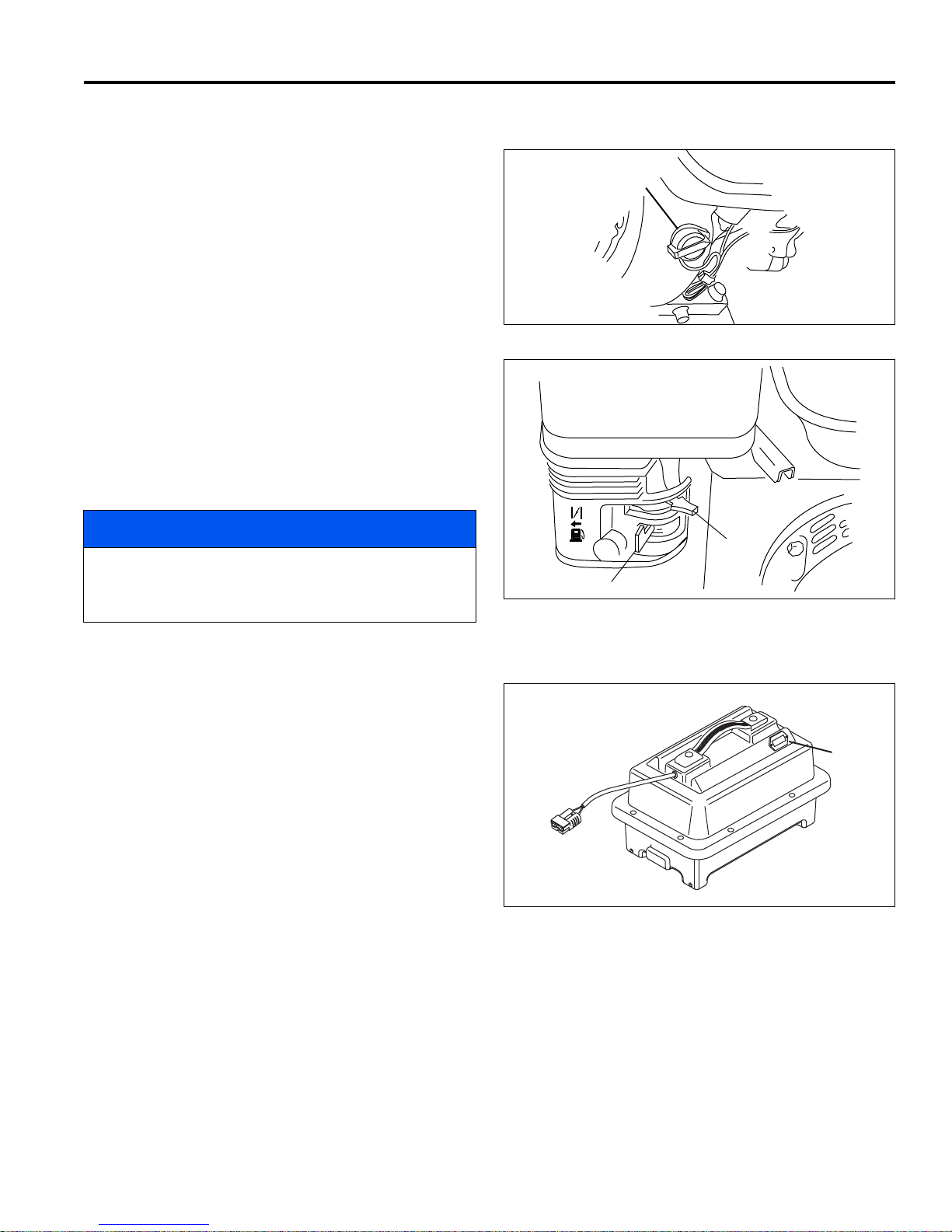
CONTROLS 4
OFF
ON
M
O
N
OFF
N
P
4.5 GAS POWER MODULE CONTROLS ___________________________________________
M. Engine Switch – The engine switch enables and
disables the engine ignition system. The engine
switch must be in the ON position for the engine to
run. Turning the engine switch to the OFF position
stops the engine.
N. Choke Lever - The choke lever opens and closes
the choke valve in the carburetor. The CLOSED
position enriches the fuel mixture for starting a cold
engine. The OPEN position provides the correct fuel
mixture for operation after starting, and for restarting
a warm engine.
P. Fuel Valve Lever - The fuel valve opens and closes
the connection between the fuel tank and the
carburetor. The fuel valve lever must be in the ON
position for the engine to run. When the engine is
not in use, leave the fuel valve lever in the OFF
position to prevent carburetor flooding, and to
reduce the possibility of fuel leakage.
Figure 4D
NOTICE
Before tipping mower back for adjustments, the fuel
lever must be moved to the OFF position to prevent
fuel from leaking into the crankcase.
4.6 BATTERY POWER MODULE CONTROLS ______________________________________
R. Battery Monitor - Located on the removable battery
pack displays battery charge level.
Figure 4E
R
Figure 4F
27
Page 28
5 OPERATION
!
!
5 OPERATION
5.1 DAILY INSPECTION________________________________________________________
2. Make sure the mower is adjusted to the required
CAUTION
The daily inspection should be performed only with
the parking brake engaged, and power connector
disconnected.
1. Perform a visual inspection of the entire unit, look for
signs of wear, loose hardware, missing or damaged
components.
5.2 INTERLOCK SYSTEM (O.P.C.) _______________________________________________
1. The Interlock System is intended to protect the operator and others from injury by stopping the reel and
drive mechanism as soon as the operator releases
the O.P.C. (Operator Presence Control) bail.
cutting height.
3. Make sure the machine is lubricated and the
transport tires are properly inflated.
4. Check the O.P.C. system.
5. Check motor connections are tight.
WARNING
Never operate equipment with the Interlock
System disconnected or malfunctioning. Do not
disconnect or bypass any switch.
2. To test the system:
a. Place mower on the kickstand.
b. Make certain reel switch is off.
3. Gen-Set Power Module: Start the engine.
4. Energize the unit.
a. Slide bail to the left and engage O.P.C. Bail.
b. The drive motor and the wheels will begin to turn.
c. Release the O.P.C. bail. The bail must
disengage, and drive motor must stop.
5. If the drive motor engages before the O.P.C. bail is
engaged or the drive motor continue to turn after the
O.P.C. bail is released; stop the unit immediately
and have the system repaired.
28
Page 29
OPERATION 5
!
!
!
5.3 OPERATING PROCEDURES _________________________________________________
CAUTION
To help prevent injury, always wear safety glasses, leather work shoes or boots, a hard hat, and ear protection.
1. Under no circumstances should the unit be started
with operator or bystanders standing in front of the
reel.
2. Never run the engine in an enclosed area.
3. Keep hands and feet away from moving parts and
cutting units. If possible, do not make adjustments
with the engine running.
4. Do not operate mower or attachments with loose,
damaged, or missing components. Whenever
possible mow when grass is dry.
5. First mow in a test area to become thoroughly
familiar with the operation of the mower and control
levers.
NOTICE
To prevent damage to the reel and bedknife never
operate the reels when they are not cutting grass.
Excessive friction and heat will develop between the
bedknife and reel and damage the cutting edge.
6. Study the area to determine the best and safest
operating procedure. Consider the height of the
grass, type of terrain, and condition of the surface.
Each condition will require certain adjustments or
precautions. Only use accessories and attachments
approved by Jacobsen.
9. Disengage the reel switch to stop blades when not
mowing.
10. Disengage the reel switch when crossing paths or
roadways. Look out for traffic.
11. Stop and inspect the equipment for damage
immediately after striking an obstruction, or if the
machine begins to vibrate abnormally. Have the
equipment repaired before resuming operation.
WARNING
Before you clean, adjust, or repair this equipment,
always disengage all drives, engage parking
brake, turf key switch OFF, and disconnect power
connector to prevent injuries.
12. Slow down and use extra care on hillsides. Use
caution when operating near drop offs.
13. Look behind and down before backing up to be sure
of a clear path. Use care when approaching blind
corners, shrubs, trees, or other objects that may
obscure vision.
14. Never use your hands to clean cutting units. Use a
brush to remove grass clippings from blades. Blades
are extremely sharp and can cause serious injuries.
7. Be aware of mower discharge direction and never
direct discharge of material toward bystanders.
Never allow anyone near the machine while in
operation. The owner/operator is responsible for
injuries inflicted to bystanders and/or damage to
their property.
CAUTION
Before mowing, pick up all debris such as rocks, toys,
and wire which can be thrown by the machine. Enter a
new area cautiously. Always operate at speeds that
allow you to have complete control of the mower.
8. Use discretion when mowing near gravel areas
(roadway, parking areas, cart paths, etc.). Stones
discharged from the mower may cause serious
injuries to bystanders and/or damage the
equipment.
29
Page 30
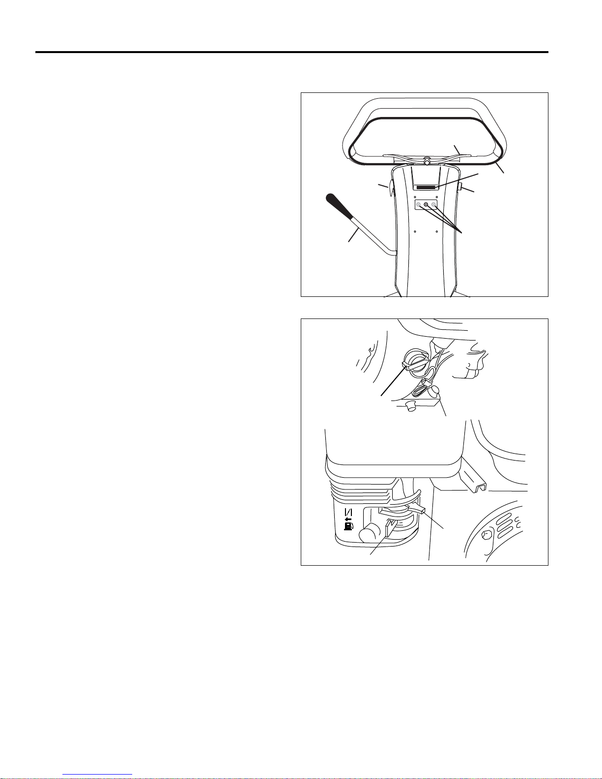
5 OPERATION
A
B
C
D
E
F
G
OFF
ON
M
O
N
OFF
N
P
5.4 STARTING/STOPPING _____________________________________________________
1. Prepare power module to energize unit.
Battery Power Module: Disconnect battery charger
and connect power connector.
Gen-Set Power Module:
a. Check oil level and fuel supply then open fuel
valve lever (P).
b. Move the choke lever (N) to the CLOSED
position.
c. Set engine switch (M) to ON and power switch
(D) to RUN position.
d. Start the engine.
e. Once engine starts move choke lever (N) to the
OPEN position.
2. Make certain O.P.C. bail (C) is disengaged, reel
switch (E) is off, and parking brake (A) is engaged.
3. Turn power switch (D) to start position and release.
LCD display (G) should show startup display for 5
seconds, then switch to system voltage.
If system fails to initialize, check to see if power
connector is properly attached.
4. Check system voltage on LCD display (G). If the
system voltage screen is not on the display, press
either of the orange buttons (F) to forward display to
the correct screen. If system voltage is low,
recharge batteries or check generator output before
operating.
5. To mow or transport unit, push O.P.C. bail (C) to the
left and engage.
6. To stop the unit, release the O.P.C. bail, engage
parking brake, and set power switch to OFF
position.
7. Battery Power Module: Disconnect power
connector and connect battery pack to charger.
Gen-Set Power Module: Turn engine switch (M) to
off position and close fuel valve (P).
Figure 5A
Figure 5B
30
Page 31
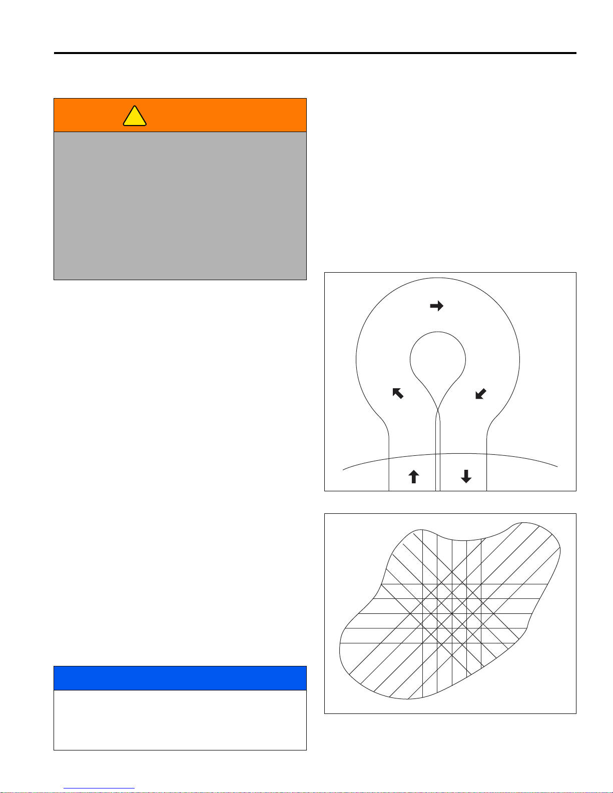
OPERATION 5
!
1
2
3
4
5
First
Mowing
Second
Mowing
Third
Mowing
Four th
Mowing
5.5 MOWING _________________________________________________________________
4. To assure complete, even cutting, overlap swaths by
WARNING
To prevent serious injuries, keep hands, feet, and
clothing away from cutting unit when the blades are
moving.
NEVER use your hands to clean cutting units. Use a
brush to remove grass clippings from blades. Blades
can be sharp and could cause injuries.
To clear obstructions from cutting unit, disengage
O.P.C. bail, engage parking brake, turn off power
switch, and disconnect power connector then remove
obstruction.
1. Turn power OFF. Remove the transport wheels (If
installed).
2. Engage the reel switch. Start the unit.
1 to 2 in., (25 to 50 mm), then make one or more
passes around the perimeter of the green to clean
ragged edges and separate the putting green
surface from the apron.
5. For a more even playing surface and neater
appearance, alter the mowing pattern each time a
green is mowed. The patterns shown in Figure 5D
are suggestions only, the operator or course
superintendent can arrange patterns to suit each
green.
6. Use caution while operating on hillside and dropoffs.
3. Position mower slightly off green.
a. Adjust traction speed paddle (B) to provide a
safe, comfortable walking speed.
b. Push handle down to lift the mower head above
the grass then engage the O.P.C. bail (C).
c. As the mower crosses the edge of the green,
lower the mower head to the ground, and
proceed across the green in a straight line.
When mowing lift up as required to keep handle
centered in slots on handle stops. Do not push
down on handle when mowing or the mower
head may lift off the grass.
d. When the opposite side of the green is reached,
push down of the handle to lift the mower head
without disengaging the O.P.C. bail, and proceed
off the green to turn around, or simply release
O.P.C. bail and turn around.
e. To turn to the right, start by turning mower
slightly to the left (2). When the mower has
moved approximately 1/2 its own width to the left,
swing it around quickly to the right (3 and 4),
guiding the mower with your right hand. This
method makes it possible to turn around quickly
with very few steps. [Figure 5C].
NOTICE
Figure 5C
To prevent damage to the reel and bedknife never
operate the reels when they are not cutting grass.
Excessive friction and heat will develop between the
bedknife and reel and damage the cutting edge.
Figure 5D
31
Page 32
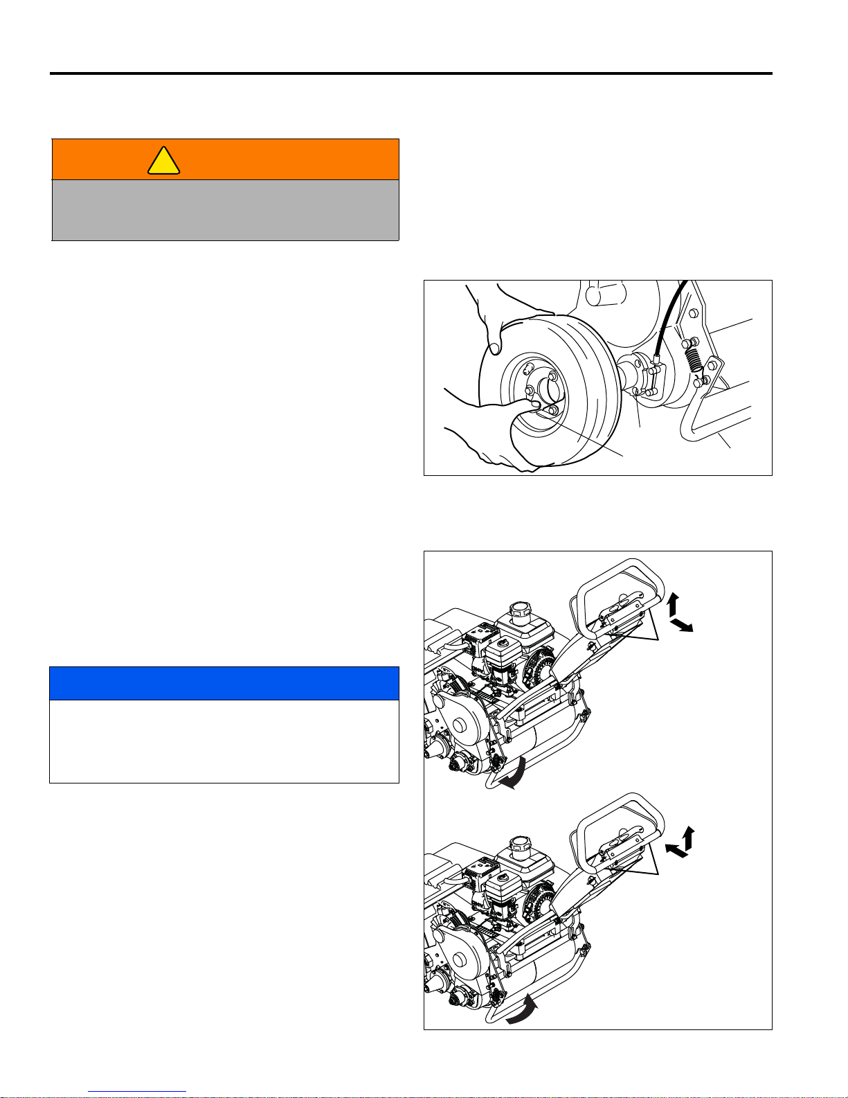
5 OPERATION
!
T
U
S
Rotate Kickstand
Down
Pull up and back
on handle
Slowly Rotate
Kickstand Up
Lift up and push
forward on handle
To p ut mower
on kickstand
To remove mower
from kickstand
5.6 TRANSPORT WHEELS (OPTIONAL) __________________________________________
4. Always disengage reel switch prior to transporting
WARNING
Always engage parking brake and disconnect power
connector before installing or removing the transport
wheels.
Transport wheels are optional accessories available
through your Jacobsen Dealer. Traction wheels are
recommended when not using the Mower Caddy to move
the mower from green to green.
1. Push and hold the kickstand against the ground then
pull the mower handle, by the lift point, back until the
mower rests on the stand (S). Engage parking brake.
2. To remove wheels, press retaining clip (T) away
from hub, and pull wheel off hub.
3. To install wheels, press retaining clip (T), place
wheel on hub, and turn the wheel backwards until
studs on back of wheel line up with holes in hub (U).
Push wheel in and release clip.
the mower more than a few feet.
5. Push the mower forward off the kickstand, start the
unit, and engage the O.P.C. bail.
6. When using a vehicle to transport the mower, apply
parking brake, turn key switch OFF, and disconnect
power connector.
Figure 5E
5.7 KICKSTAND ______________________________________________________________
1. To put the mower on the kickstand:
a. Use your foot to rotate kickstand down to the
ground. Hold kickstand on the ground.
b. Pull up and back on lower portion of D handle
until mower weight is on kickstand, and traction
roller is off the ground.
NOTICE
To prevent damage to the D handle, only use the
lower portion of the handle to put mower on the
kickstand. Pulling on upper portion of D handle may
cause damage to the handle.
2. To remove mower from kick stand:
a. Place foot behind kickstand.
b. Push mower forward while lifting slightly on the
lower portion of D handle.
c. When traction roller is on the ground, use your
foot to slowly allow kickstand to rotate up to rest
against frame. Do not allow kick stand to snap
back against frame.
32
Figure 5F
Page 33
OPERATION 5
!
!
5.8 GRASS CATCHER _________________________________________________________
1. When the basket is about two thirds (2/3) full of grass
clippings, move the mower off the green.
2. Stop on a flat surface, disengage O.P.C. bail,
engage parking brake, turn key switch OFF, and
disconnect power connector.
3. Remove and empty the grass clippings from the
mower.
To prevent serious injury, always disengage
O.P.C. bail and disconnect power connector
before emptying grass catcher.
5.9 DAILY MAINTENANCE______________________________________________________
WARNING
1. Park the mower on a flat, level surface. Engage
parking brake, and turn key switch to off position.
2. Grease and lubricate all points if required. Use a
manual grease gun only, do not use compressed air.
NOTICE
To prevent damage to reel motor, do not over grease
reel bearings. Damage of this nature is not covered
by the factory warranty.
3. To prevent fires, wash the mower after each use.
NOTICE
Battery Power Modules: Disconnect battery
connector and remove the battery pack from the
mower before washing.
a. Use only fresh water for cleaning your
equipment.
NOTICE
Use of salt water or effluent water will encourage rust
and corrosion of metal parts resulting in premature
deterioration or failure. Damage of this nature is not
covered by the factory warranty.
b. Do not use high pressure spray.
c. Do not spray water directly at electrical
connectors, generator, motors, or controller
Battery Power Module:
4. Disconnect power connector and connect battery
pack to charger.
Gen-Set Power Module:
5. Fill fuel tank at the end of each operating day. Do
not fill above the fuel strainer shoulder. Close fuel
valve when unit is not in use.
Use clean, fresh, unleaded gasoline, 86 octane
minimum. Refer to the engine’s operator manual for
fuel recommendations when using blended fuel.
Handle fuel with care - it is highly flammable. Use an
approved container. The spout must fit inside the fuel
filler neck. Avoid using cans and funnels to transfer fuel.
WARNING
Never remove the fuel cap from the fuel tank, or add
fuel, when the engine is running or while the engine is
hot.
Do not smoke when handling fuel. Never fill or drain
the fuel tank indoors.
Do not spill fuel and clean spilled fuel immediately.
Never handle or store fuel containers near an open
flame or any device that may create sparks and ignite
the fuel or fuel vapors.
Be sure to reinstall and tighten fuel cap securely.
d. Do not spray water into the cooling fins or the
engine air intake.
NOTICE
Do not wash a hot or running engine. Use
compressed air to clean the engine.
6. Store fuel according to local, state or federal
ordinances and recommendations from your fuel
supplier.
7. Check the engine oil at the start and end of each
day, before starting the engine. If the oil level is low,
remove the oil filler cap and add oil as required. Do
not overfill.
33
Page 34
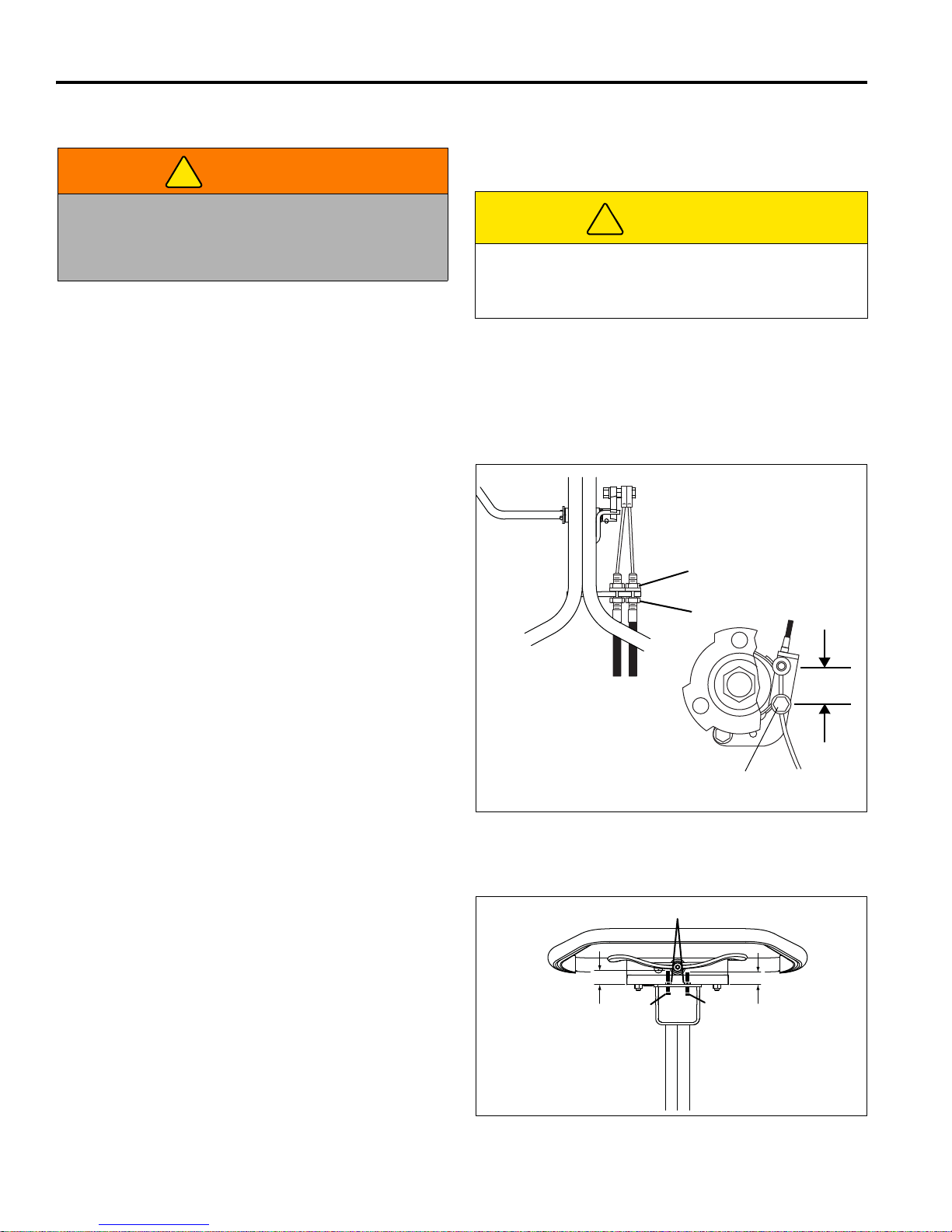
6 ADJUSTMENTS (ALL UNITS)
!
!
HANDLE
BRAKE BAND
A
B
C
1-1/2”
(38 mm)
1-1/16 in.
(27 mm)
7/8 in.
(22 mm)
X
Y
Z
6 ADJUSTMENTS (ALL UNITS)
6.1 GENERAL________________________________________________________________
3. Long hair, jewelry, or loose fitting clothing may get
WARNING
Before you adjust, clean, or repair this equipment,
always disengage all drives, engage parking brake,
turn key switch OFF, and disconnect power connector
to prevent serious injury.
1. Adjustments and maintenance should always be
performed by a qualified technician. If proper
adjustment cannot be made, contact an authorized
Jacobsen Dealer.
2. Replace, do not adjust, worn or damaged
components.
6.2 BRAKE __________________________________________________________________
A properly adjusted brake requires 10 lbs. pull at top of
brake lever to engage and must have 1-1/2” (38 mm)
center to center when released.
tangled in moving parts.
CAUTION
Be careful to prevent entrapment of the hands and
fingers between moving and fixed components of the
machine.
4. Do not change speed limit settings or overspeed the
drive motors.
1. Minor adjustments are made at the handle. Loosen
nut (A), turn nut (B) to adjust the brake cable, then
tighten nut (A).
2. If adjustments cannot be made at the handle,
remove the transport wheel, and make the
adjustment at the brake band.
3. Loosen screw (C) and pull cable to obtain desired
brake tension. Tighten screw (C). Readjust (A) and
(B).
Figure 6A
6.3 SPEED PADDLE STOPS ____________________________________________________
1. Loosen both nuts (X).
2. Adjust positive paddle stop (Y) to 7/8 in. (22 mm).
3. Adjust negative paddle stop (Z) to 1-1/16 in. (27
mm).
4. Tighten nuts (X) to lock adjustment.
After adjusting paddle stops, the controller speed paddle
calibration must be reset. [See Section 4.3].
34
Figure 6B
Page 35
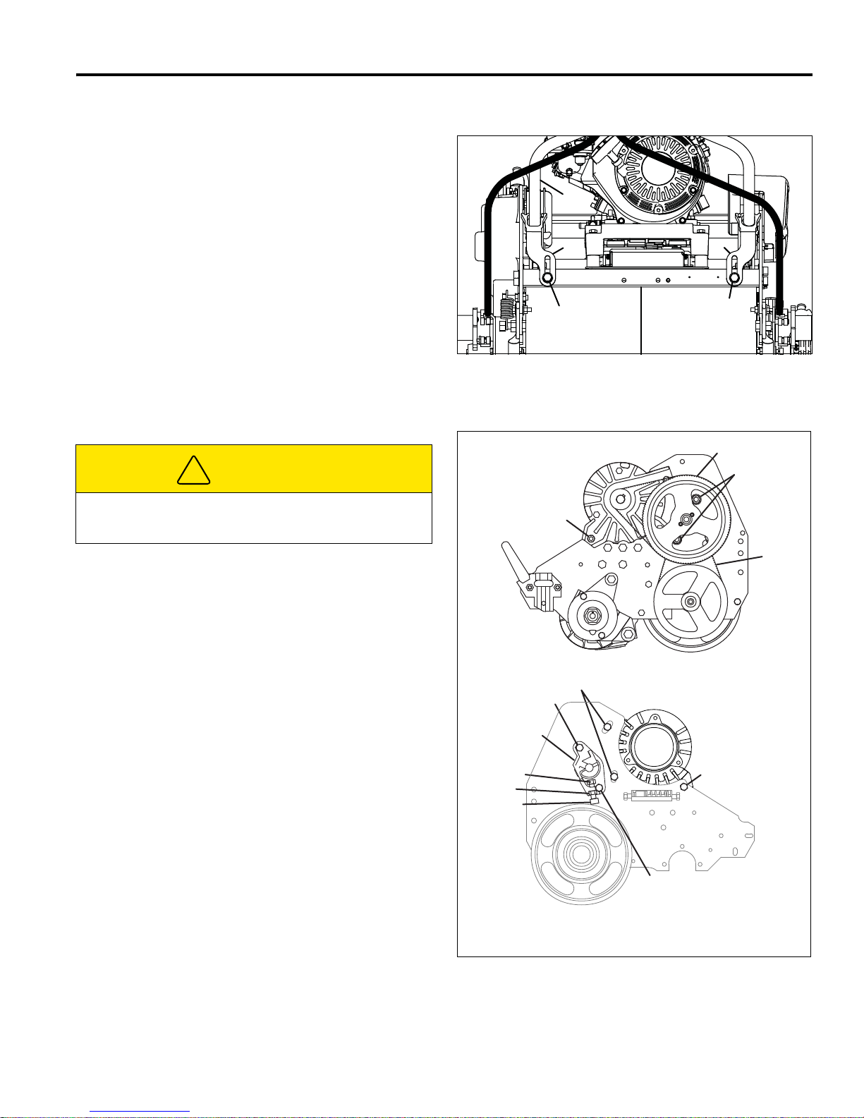
ADJUSTMENTS (ALL UNITS) 6
EE
F
D
D
!
G
M
H
J
J
J
K
L
P
Fixed Head Mower Shown
Floating Head Mower Similar
P
P
N
6.4 HANDLE _________________________________________________________________
1. To adjust the angle of the handle bar (F), loosen
screw (D) on both sides of the mower and adjust the
handle bar to the desired position.
2. After adjusting handle bar, adjust bracket (E) so that
the handle bar just rests on the bottom of the slot in
bracket. Tighten screw (D). Check that handle
moves from bottom to top of slot in bracket (E)
without binding.
Figure 6C
6.5 TRACTION BELTS _________________________________________________________
.
CAUTION
To prevent permanent damage to the belt, do not
twist, fold, bend. or overtighten the belt.
1. To adjust belt (G), assemble 5/16-18 x 1” hex head
screw (K) and 5/16-18 hex nut (L) to bottom of
bearing bracket (H). Loosen nuts (J).
2. Place bedknife gauge bar (M) on top of roller and
under screw (K). Tighten screw (K) until belt (G)
deflects 1/10” (2.5 mm) with 1 ~ 2 lb (0.45 ~ 0.91
kg) load applied at mid span.
3. Tighten nuts (J) and remove 5/16-18 x 1” screw (K)
and lower nut (L).
4. Place hardware (K and L) in a safe place for future
adjustments.
5. To adjust belt (N), loosen pivot hardware (P), and
pivot motor housing towards front of mower until belt
deflects 1/10” (2.5 mm) with 1 ~ 2 lb. (0.45 ~ 0.91
kg) load applied at mid span. Tighten hardware (P).
Figure 6D
35
Page 36
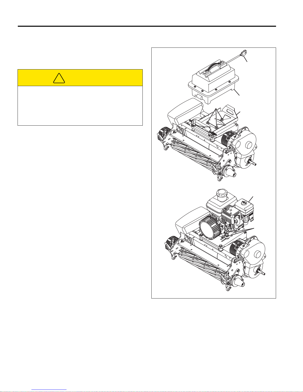
6 ADJUSTMENTS (ALL UNITS)
!
R
S
W
Battery Power Module
Gen-Set Power Module
V
U
T
6.6 FRONT ROLLER WEIGHT ___________________________________________________
The weight on the front roller is adjustable. Adjust the
front roller weight as required to meet your turf needs.
CAUTION
To prevent injury or property damage, place mower
on kickstand or support mower handle before
removing battery pack.
Full battery packs weigh approximately 60 lbs (27.2
kg). Use proper lifting techniques when moving them.
1. Battery Power Module: To adjust front roller weight,
disconnect power connector (R), and remove battery
pack (S). Loosen hardware (T), place battery pack
back onto mower, and slide battery mounting tray (U)
as required.
Gen-Set Power Module: Loosen engine mounting
hardware (V) and slide engine (W) as required.
2. To adjust the front roller weight:
a. To increase front roller weight, slide battery tray
(U), or engine (W) towards front of mower.
b. To decrease front roller weight, slide battery tray
(U), or engine (W) towards rear of mower.
c. Use the decal on the power module mount as a
guide for adjusting the front roller weight.
Aligning the oil drain (Gen-Set) or the V-notch in
the battery tray (Battery Tray) with the desired
line on the decal allows for consistent front roller
weight setting.
3. Battery Power Module: When desired weight is
attained, measure distance from edge of power
module mount to tray (U). Remove battery pack (S).
Recheck measured dimension and tighten hardware
(R).
Gen-Set Power Module: Tighten engine mounting
hardware (V).
Figure 6E
36
Page 37
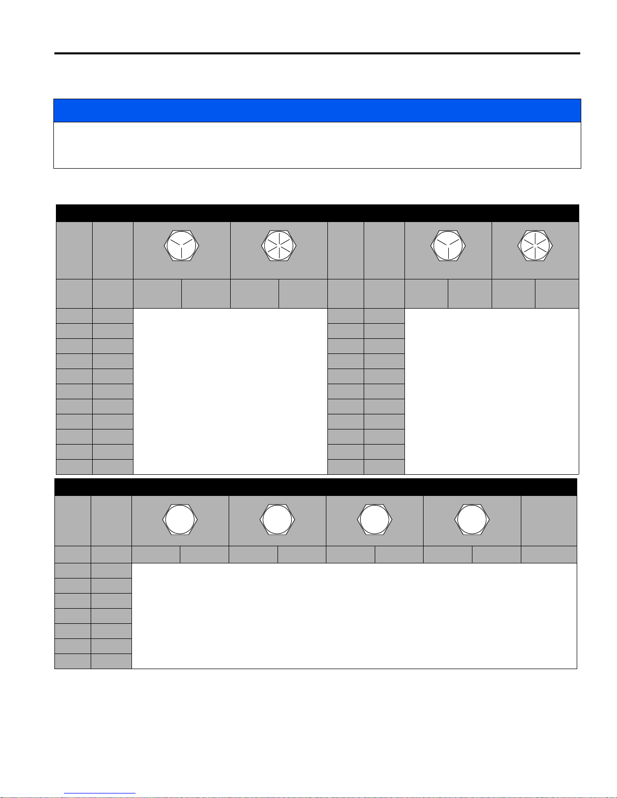
ADJUSTMENTS (ALL UNITS) 6
4.6
8.8
10.9
12.9
6.7 TORQUE SPECIFICATION ___________________________________________________
NOTICE
All torque values included in these charts are approximate and are for reference only. Use of these torque values is
at your sole risk. Jacobsen is not responsible for any loss, claim, or damage arising from the use of these charts.
Extreme caution should always be used when using any torque value.
Jacobsen uses Grade 5 Plated bolts as standard, unless otherwise noted. For tightening plated bolts, use the value
given for lubricated.
AMERICAN NATIONAL STANDARD FASTENERS
SIZE UNITS GRADE 5 GRADE 8 SIZE UNITS GRADE 5 GRADE 8
Lubricated Dry Lubricated Dry Lubri-
cated
#6-32 in-lb (Nm) – 20 (2.3) – – 7/16-14 ft-lb (Nm) 37 (50.1) 50 (67.8) 53 (71.8) 70 (94.9)
#8-32 in-lb (Nm) – 24 (2.7) – 30 (3.4) 7/16-20 ft-lb (Nm) 42 (56.9) 55 (74.6) 59 (80.0) 78 (105)
#10-24 in-lb (Nm) – 35 (4.0) – 45 (5.1) 1/2-13 ft-lb (Nm) 57 (77.2) 75 (101) 80 (108) 107 (145)
#10-32 in-lb (Nm) – 40 (4.5) – 50 (5.7) 1/2-20 ft-lb (Nm) 64 (86.7) 85 (115) 90 (122) 120 (162)
#12-24 in-lb (Nm) – 50 (5.7) – 65 (7.3) 9/16-12 ft-lb (Nm) 82 (111) 109 (148) 115 (156) 154 (209)
1/4-20 in-lb (Nm) 75 (8.4) 100 (11.3) 107 (12.1) 143 (16.1) 9/16-18 ft-lb (Nm) 92 (124) 122 (165) 129 (174) 172 (233)
1/4-28 in-lb (Nm) 85 (9.6) 115 (13.0) 120 (13.5) 163 (18.4) 5/8-11 ft-lb (Nm) 113 (153) 151 (204) 159 (215) 211 (286)
5/16-18 in-lb (Nm) 157 (17.7) 210 (23.7) 220 (24.8) 305 (34.4) 5/8-18 ft-lb (Nm) 128 (173) 170 (230) 180 (244) 240 (325)
5/16-24 in-lb (Nm) 173 (19.5) 230 (26.0) 245 (27.6) 325 (36.7) 3/4-10 ft-lb (Nm) 200 (271) 266 (360) 282 (382) 376 (509)
3/8-16 ft-lb (Nm) 23 (31.1) 31 (42.0) 32 (43.3) 44 (59.6) 3/4-16 ft-lb (Nm) 223 (302) 298 404 315 (427) 420 (569)
3/8-24 ft-lb (Nm) 26 (35.2) 35 (47.4) 37 (50.1) 50 (67.8) 7/8-14 ft-lb (Nm) 355 (481) 473 (641) 500 (678) 668 (905)
Dry Lubri-
cated
Dry
SIZE UNITS
Lubricated Dry Lubricated Dry Lubricated Dry Lubricated Dry
M4 Nm (in-lb)––––––3.83 (34)5.11 (45)2.0 (18)
M5 Nm (in-lb) 1.80 (16) 2.40 (21) 4.63 (41) 6.18 (54) 6.63 (59) 8.84 (78) 7.75 (68) 10.3 (910 4.0 (35)
M6 Nm (in-lb) 3.05 (27) 4.07 (36) 7.87 (69) 10.5 (93) 11.3 (102) 15.0 (133) 13.2 (117) 17.6 (156) 6.8 (60)
M8 Nm (in-lb) 7.41 (65) 9.98 (88) 19.1 (69) 25.5 (226) 27.3 (241) 36.5 (323) 32.0 (283) 42.6 (377) 17.0 (150)
M10 Nm (ft-lb) 14.7 (11) 19.6 (14) 37.8 (29) 50.5 (37) 54.1 (40) 72.2 (53) 63.3 (46) 84.4 (62) 33.9 (25)
M12 Nm (ft-lb) 25.6 (19) 34.1 (25) 66.0 (48) 88.0 (65) 94.5 (70) 125 (92) 110 (81) 147 (108) 61.0 (45)
M14 Nm (ft-lb) 40.8 (30) 54.3 (40) 105 (77) 140 (103) 150 (110) 200 (147) 175 (129) 234 (172) 94.9 (70)
METRIC FASTENERS
Non Critical
Fasteners
into
Aluminum
37
Page 38
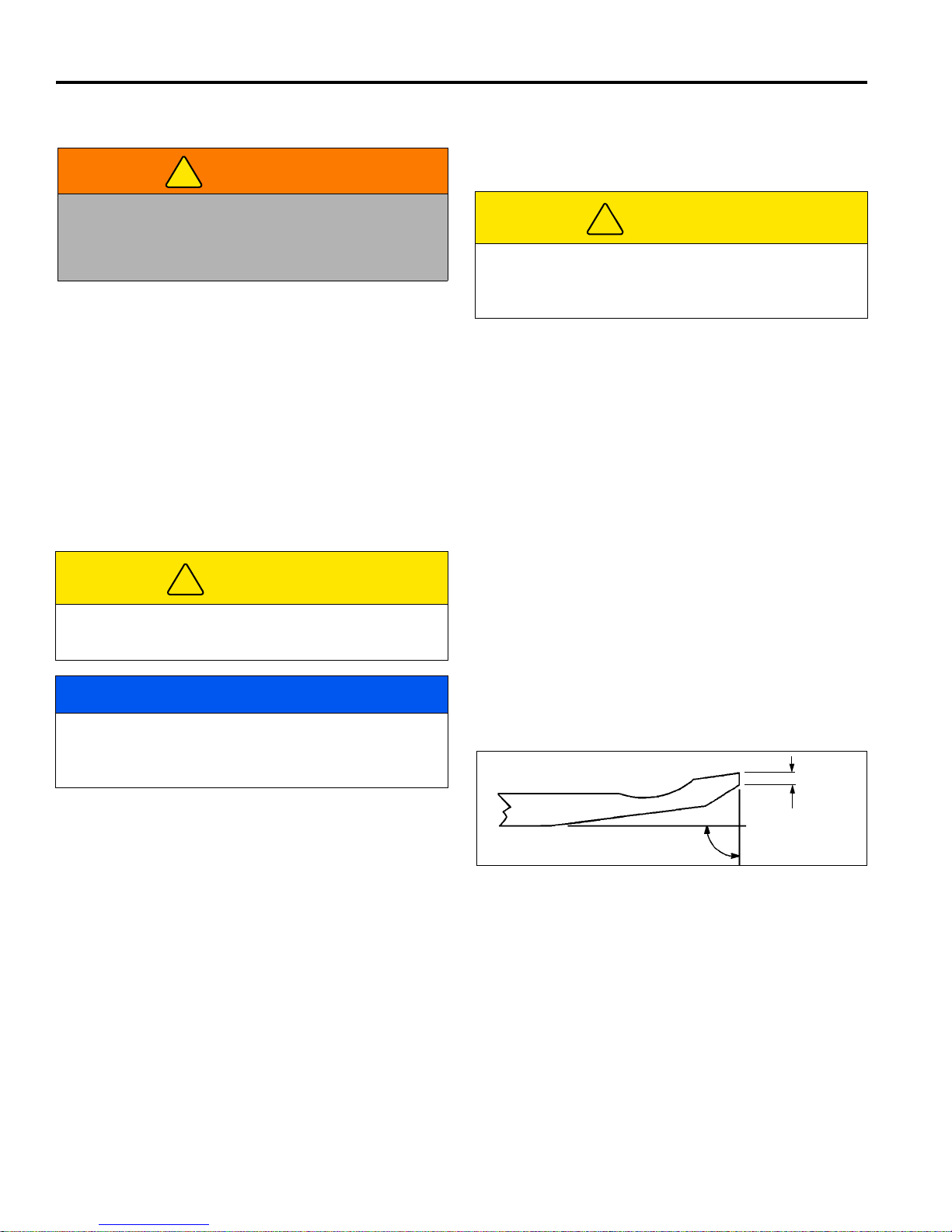
7 FIXED HEAD REEL ADJUSTMENTS
!
!
!
°
°
1/32”
(0.8 mm)
7 FIXED HEAD REEL ADJUSTMENTS
7.1 GENERAL________________________________________________________________
3. Long hair, jewelry, or loose fitting clothing may get
WARNING
Before you adjust, clean, or repair this equipment,
always disengage all drives, engage parking brake,
turn power off and disconnect power connector to
prevent serious injury.
1. Adjustments and maintenance should always be
performed by a qualified technician. If proper
adjustment cannot be made, contact an authorized
Jacobsen Dealer.
2. Replace, do not adjust, worn or damaged
components.
7.2 REEL TO BEDKNIFE _______________________________________________________
(Pre-adjustment Check)
1. Check the reel bearings for end play or radial play. If
there is any abnormal movement of the reel, up and
down, or side to side, adjust, or replace components
as needed.
CAUTION
tangled in moving parts.
CAUTION
Be careful to prevent entrapment of the hands and
fingers between moving and fixed components of the
machine.
4. Do not change speed limit settings or overspeed the
drive motors.
4. Proper reel-to-bedknife adjustment is critical. A gap
of 0.001 to 0.003” (0.025 to 0.076 mm) must be
maintained across the entire length of the reel and
bedknife.
5. The reel must be parallel to the bedknife. An
improperly adjusted reel will lose its sharp edges
prematurely and may result in serious damage to
the reel and bedknife.
Handle the reel with extreme care to prevent personal
injury and damage to the cutting edges.
NOTICE
Before tipping mower back for adjustments, the fuel
lever must be moved to the OFF position to prevent
fuel from leaking into the crankcase.
2. Inspect the reel blades and bedknife to insure good
sharp edges without bends or nicks.
a. The cutting edges of the reel blades and bedknife
must be sharp, free of burrs, and show no signs
of rounding off.
b. The bedknife and bedknife backing must be
securely tightened. The bedknife must be
straight and sharp.
c. A flat surface of at least 1/32 in. (0.8 mm)
minimum must be maintained on the front face of
the bedknife. Use a standard flat file to dress the
bedknife.
3. If wear or damage is beyond the point where the
reel or bedknife can be corrected by the lapping
process, they must be reground.
6. Grass conditions will also affect the adjustment.
a. Dry, sparse conditions will require a wider gap to
prevent heat buildup and damage to the reel and
bedknife.
b. High quality grass with a good moisture content
requires a closer gap (near zero).
Figure 7A
38
Page 39
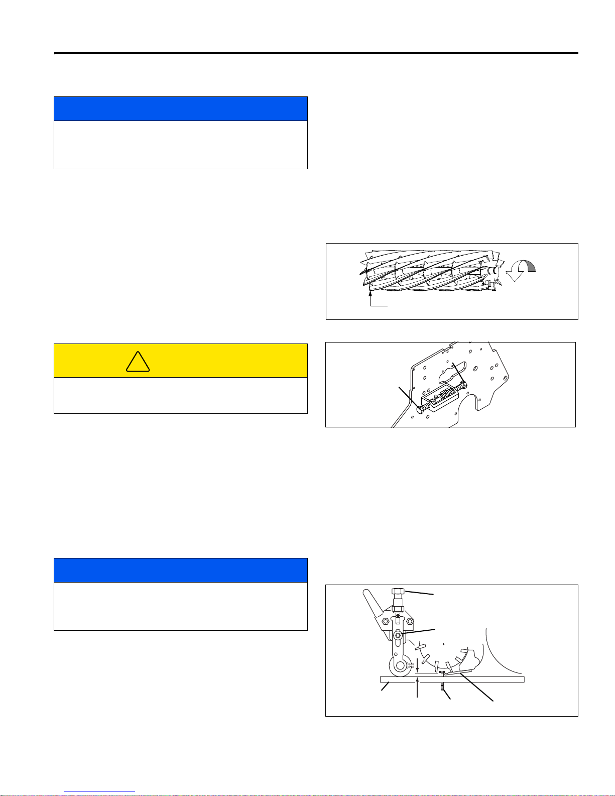
FIXED HEAD REEL ADJUSTMENTS 7
!
Rotation
Leading Edge
A
B
C
D
E
F
G
H
7.3 BEDKNIFE ADJUSTMENT ___________________________________________________
a. Slide a feeler gauge or shim stock 0.001 - 0.003
NOTICE
Before tipping mower back for adjustments, the fuel
lever must be moved to the OFF position to prevent
fuel from leaking into the crankcase.
1. Adjuster (A) is used to increase or decrease the
spring load on the bedknife. Adjuster (B) is used to
move the bedknife to the reel or away from the reel.
2. Once the spring is totally collapsed as a result of
many adjustments, the bedknife cannot be moved.
Back-off adjuster (A) before adjusting (B).
3. For most applications, compress the spring to 1 in.,
(25 mm).
4. Start adjustment at the leading edge of the reel,
followed by the trailing end. The leading end of the
reel blade is the end that passes over the bedknife
first during normal rotation.
in., (0.025 - 0.075 mm) between the reel blade
and the bedknife. Do not turn the reel.
b. Adjust the trailing end of the reel in the same
manner, then recheck the adjustment at the
leading end.
c. When the reel and bedknife are properly
adjusted, the reel will spin freely and will cut a
piece of newspaper along the full length of the
reel when the paper is held at 90° to the
bedknife.
Figure 7B
CAUTION
Handle the reel with extreme care to prevent personal
injury and damage to the cutting edges.
5. Turn adjuster (B) clockwise to bring the bedknife
closer to the reel or counterclockwise to back the
bedknife away from the reel.
7.4 CUTTING HEIGHT _________________________________________________________
Note: Make sure the bedknife is properly adjusted before
setting the cutting height. [See Section 7.3].
1. Push kickstand down and tip mower back on it’s
handle.
NOTICE
Gen-Set Power Modules: Do not leave the mower
tipped back for an extended length of time or oil may
migrate into the combustion chamber.
2. Loosen nuts (D) on both sides just enough to allow
knob (C) to raise the front roller. Raise both sides an
equal amount.
3. Set gauge screw (G) to the desired cutting height
(F). Measure from the gauge bar (E) to the
underside of the screw head (G) then tighten wing
nut to lock the adjustment.
4. Place gauge bar between front roller and traction
roller, near the outer end of the rollers.
Figure 7C
5. Slide screw head over bedknife (H) and adjust knob
(C) so roller just contacts the gauge bar. Tighten nut
(D).
6. Repeat Steps 4 and 5 on the opposite end of the
reel then tighten nuts (D). Recheck and readjust the
cutting height if necessary.
Figure 7D
39
Page 40
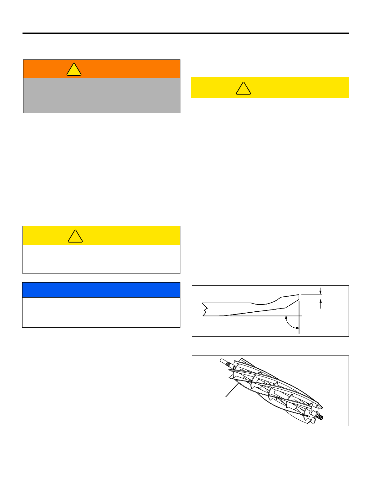
8 FLOATING HEAD REEL ADJUSTMENTS
!
!
!
°
°
1/32”
(0.8 mm)
Leading Edge
LF025
8 FLOATING HEAD REEL ADJUSTMENTS
8.1 GENERAL________________________________________________________________
3. Long hair, jewelry or loose fitting clothing may get
WARNING
Before you adjust, clean, or repair this equipment,
always disengage all drives, engage parking brake,
turn power off and disconnect power connector to
prevent serious injury.
1. Adjustments and maintenance should always be
performed by a qualified technician. If proper
adjustment cannot be made, contact an authorized
Jacobsen Dealer.
2. Replace, do not adjust, worn or damaged
components.
8.2 BEDKNIFE-TO-REEL _______________________________________________________
(Pre-adjustment Check)
tangled in moving parts.
CAUTION
Be careful to prevent entrapment of the hands and
fingers between moving and fixed components of the
machine.
4. Do not change speed limit settings or overspeed the
drive motors.
1. Check the reel bearings for end play or radial play.
There should be no end play or radial play. See Section
8.6.
CAUTION
To prevent personal injury and damage to the cutting
edges, wear gloves and handle the reel and bedknife
with extreme care.
NOTICE
Before tipping mower back for adjustments, the fuel
lever must be moved to the OFF position to prevent
fuel from leaking into the crankcase.
2. Inspect the reel blades and bedknife to insure good
sharp edges without bends or nicks.
a. The leading edge of the reel blades must be sharp,
free of burrs and show no signs of rounding off.
b. The bedknife and bedknife backing must be
securely tightened. The bedknife must be straight
and sharp.
5. The reel must be parallel to the bedknife. An
improperly adjusted reel will lose its sharp edges
prematurely and may result in serious damage to the
reel and bedknife.
6. Grass conditions will also affect the adjustment.
a. Dry, sparse conditions will require a wider gap to
prevent heat buildup and damage to the reel and
bedknife.
b. High quality grass with a good moisture content
requires a closer gap (near zero).
Figure 8A
c. A flat surface of at least 1/32 in. (0.8 mm) minimum
must be maintained on the front face of the bedknife. Use a standard flat file to dress the bedknife.
3. If wear or damage is beyond the point where the reel
or bedknife can be corrected by the lapping process,
they must be reground.
4. Proper reel-to-bedknife adjustment is critical. A gap of
0.001 to 0.003” (0.025 to 0.076 mm) must be
maintained across the entire length of the reel and
bedknife.
40
Figure 8B
Page 41
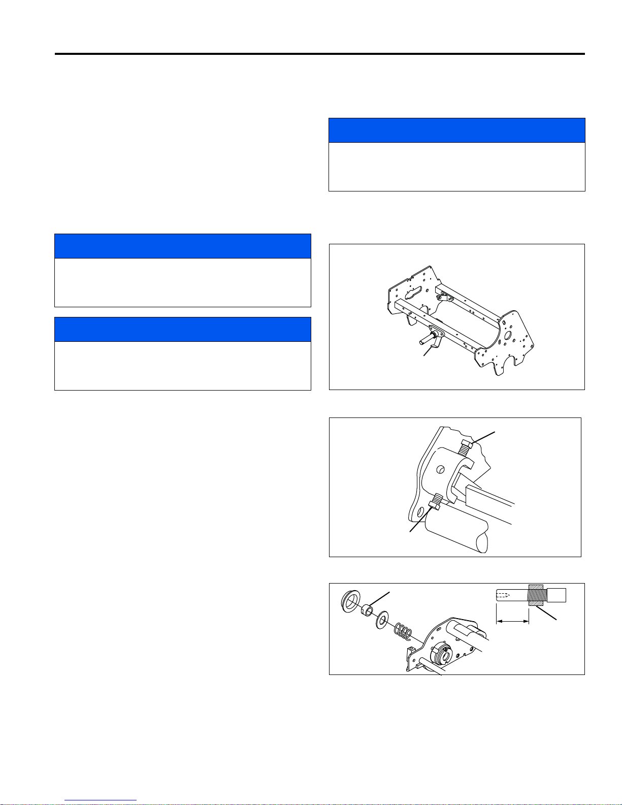
FLOATING HEAD REEL ADJUSTMENTS 8
A
GKV-1
B
C
P
P
1-27/32 in.
(46.8 mm)
8.3 BEDKNIFE ADJUSTMENT ___________________________________________________
1. Read Section 8.2 before making the adjustment.
2. Start adjustment at the leading end of the reel,
followed by the trailing end. The leading end of the
reel blades is that end which passes over the
bedknife first during normal reel rotation.
3. Additional access to bedknife adjusting hardware (B
and C) can be obtained by pressing the limit bracket
(A) away from the reel as the mower is tipped back
onto it’s handle. This allows the back side of the reel
to pivot down and away from the frame.
NOTICE
Before tipping mower back for adjustments, the fuel
lever must be moved to the OFF position to prevent
fuel from leaking into the crankcase.
NOTICE
Gen-Set Power Modules: Do not leave the mower
tipped back for an extended length of time or oil may
migrate into the combustion chamber.
full length of the reel, when the paper is held at
90° to the bedknife.
NOTICE
Avoid excessive tightening or serious damage may
result to bedknife and reel blades. Reels must turn
freely.
4. Return mower to upright position. Limit bracket (A)
is spring loaded and should latch into bracket on
reel.
4. Use adjusters (B and C), to adjust gap. Loosen
bottom adjuster (C) and turn top adjuster (B) down
(Clockwise) to close gap.
a. Slide a feeler gauge or shim stock 0.001” - 0.003”
(0.025 - 0.075 mm) between the reel blade and
the bedknife. Do not turn the reel.
b. Adjust the trailing end of the reel to the same
gap in a similar manner then recheck the
adjustment at the leading end.
c. When the reel is properly adjusted to the
bedknife, the reel will spin freely and you should
be able to cut a piece of newspaper, along the
Figure 8C
8.4 REEL BEARING ___________________________________________________________
Any end play or radial play indicates bad bearings, a
weak tension spring or a backed off nut.
1. Check bearing housing mounting hardware. Tighten
or replace components as required. Carefully clean
threads with degreaser.
2. Apply a medium strength grade of Loctite to nut (P),
then thread nut onto the reel shaft until the nut is
1-27/32 in. (46.8 mm) from the end of the reel shaft.
Figure 8E
3. Fill reel bearing housings with NLGI - Grade O
grease after adjusting spring.
41
Page 42
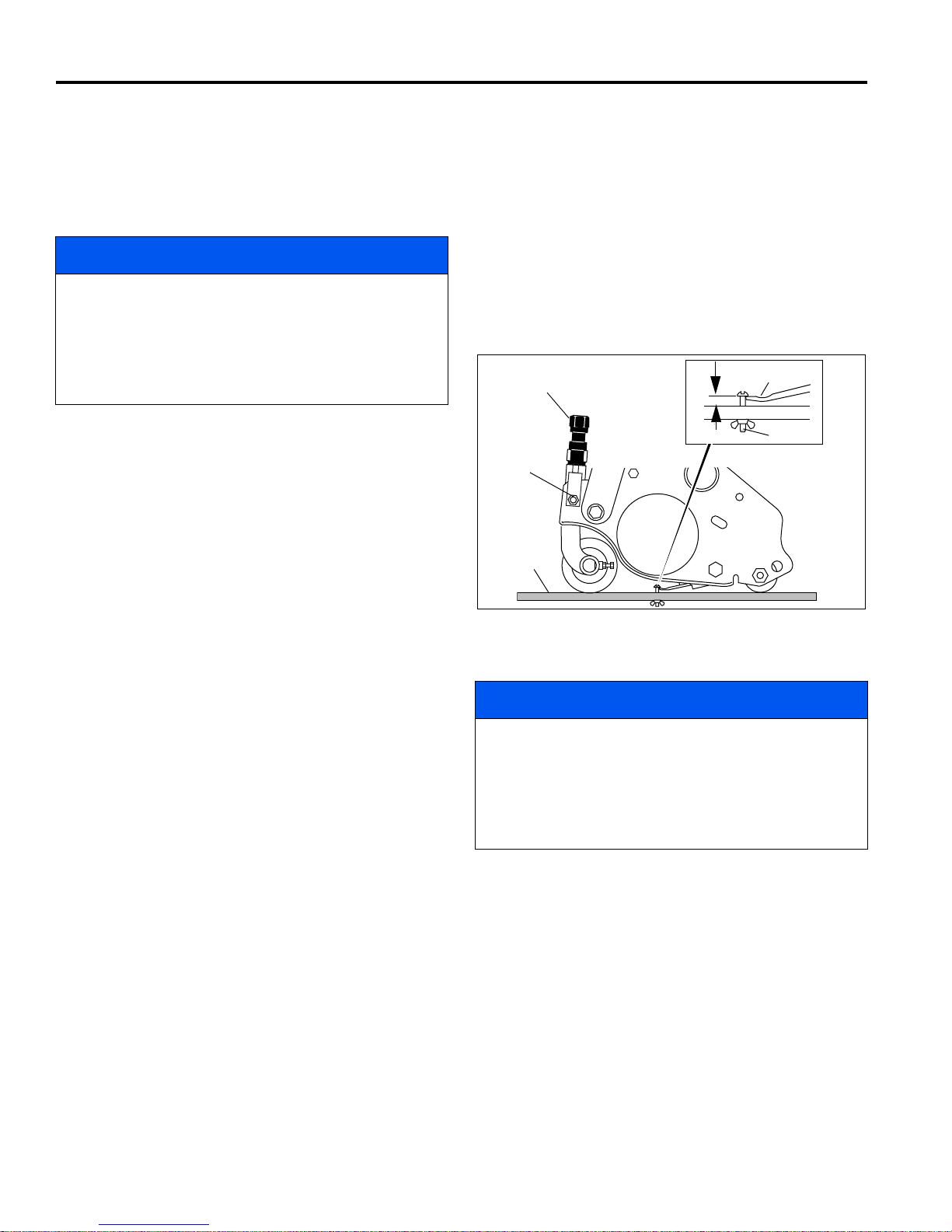
8 FLOATING HEAD REEL ADJUSTMENTS
F
K
G
E
H
J
8.5 CUTTING HEIGHT _________________________________________________________
Note: Always make the reel to bedknife adjustment
before adjusting height of cut. (Sections 8.2 and 8.3).
6. Place gauge (E) across bottom of front and rear
rollers near one end of roller.
1. Push kickstand down and tip mower back on it’s
handle.
NOTICE
Gen-Set Power Modules: Before tipping mower back
for adjustments, the fuel lever must be moved to the
OFF position to prevent fuel from leaking into the
crankcase. Do not leave the mower tipped back for an
extended length of time or oil may migrate into the
combustion chamber.
4. Set desired cutting height on the gauge (E).
a. Measure distance between the underside of
screw head and gauge block surface (F).
b. Adjust screw (H) to obtain desired height then
tighten the wing nut.
5. Loosen the nuts on the front roller brackets (G) just
enough to allow the adjuster knob (K) to raise or
lower the front roller.
7. Slide the head of gauge screw (H) over the bedknife
(L) and adjust the knob (K) to close the gap between
the screw head and bedknife. Then tighten locknut
(G).
8. Repeat Steps 4 and 5 on opposite end. Complete
adjustment to one end before adjusting opposite end.
9. Tighten nuts (G) and recheck each end.
Figure 8F
8.6 REEL ASSEMBLY REMOVAL________________________________________________
The reel assembly can be removed for maintenance or to
use a different reel.
1. Remove hairpin and washer and slide the lift hangers
off the pins.
2. Disconnect motor electrical connectors and reel
ground wire. Whenever the reel motors are
disconnected from the harness, cover the
connectors on the motor to prevent debris from
entering motor.
3. Remove hairpin and flat washer and lift panhard rod
off of reel bolt.
Gen-Set Power Modules: Before tipping mower back
for adjustments, the fuel lever must be moved to the
OFF position to prevent fuel from leaking into the
crankcase. Do not leave the mower tipped back for an
extended length of time or oil may migrate into the
combustion chamber.
4. Tip the unit back onto the handle and slide the reel
away from the mower.
5. Reel assembly is reverse of removal.
NOTICE
42
Page 43
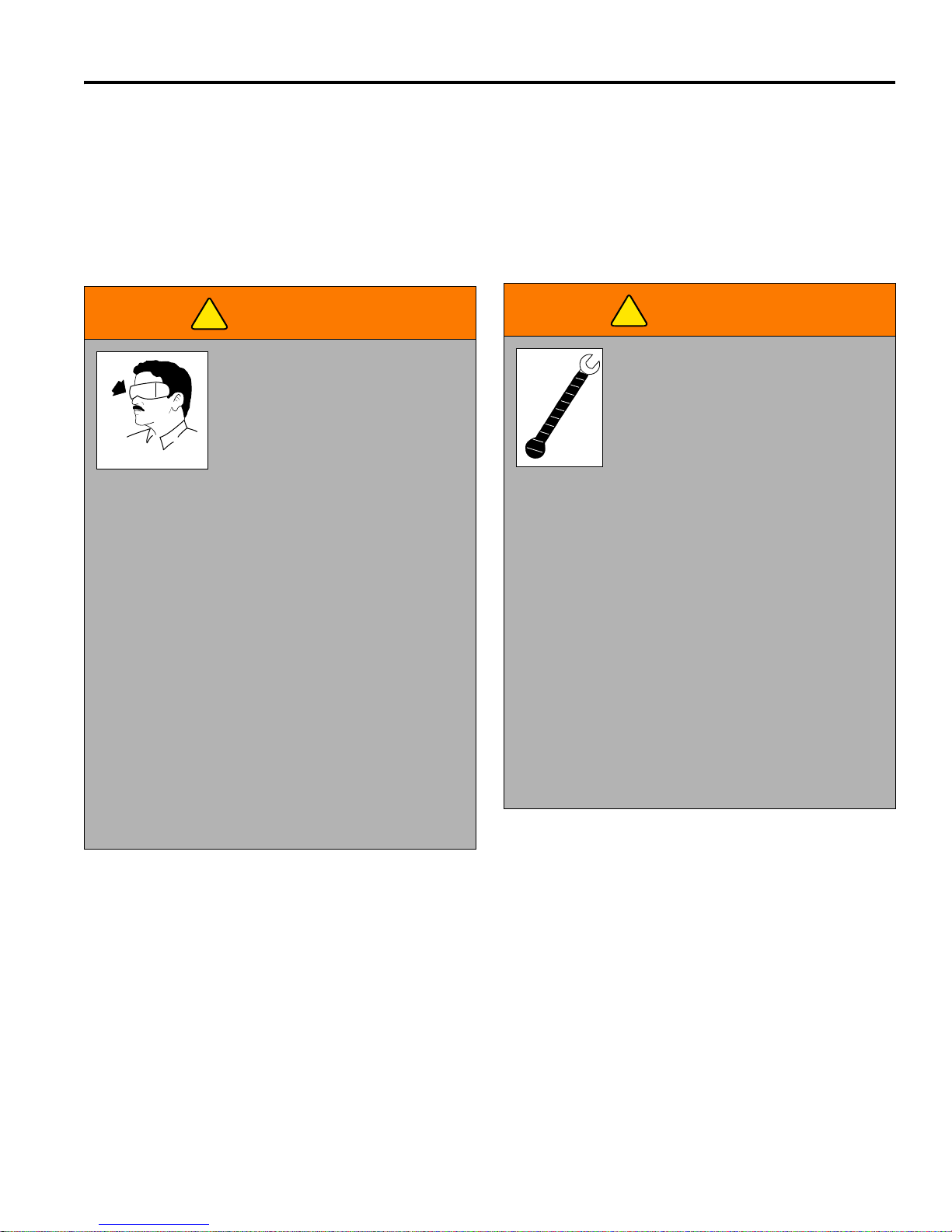
BATTERY POWER MODULE 9
!
TR016
!
TR017
9 BATTERY POWER MODULE
9.1 SAFETY__________________________________________________________________
Batteries contain dilute sulfuric acid which can result in severe burns.
Hydrogen gas is formed within a battery during the charging cycle. Hydrogen in concentrations of 4% and higher are
explosive and can be ignited by open flame or an electrical spark. A battery explosion will cause sulfuric acid and
battery components to be thrown over a large area with considerable force.
Always observe the following warnings when working on or near batteries:
WARNING
The electrolyte in a storage battery
is a dilute acid which can cause
severe burns to the skin and eyes.
Treat all electrolyte spills to the
body and eyes with extended
flushing with clear water. Contact a
physician immediately. Always wear
a safety shield or approved safety goggles when
charging batteries.
Hydrogen is explosive in concentrations as low as 4%
and is generated in the charging cycle of electric
mowers. Because it is lighter than air, it will collect in
the ceiling of buildings necessitating proper
ventilation. Air exchanges of 5 changes per hour is
considered the minimum requirement.
Never smoke around batteries.
Never charge batteries in an area that has open flame
or electrical equipment that could cause an electrical
arc.
Be sure that the key switch is off, all electrical
accessories are turned off and power connector is
disconnected before starting work on vehicle.
WARNING
Wrap wrenches with vinyl tape to
prevent the possibility of a dropped
wrench from ‘shorting out’ a battery,
which could result in an explosion and
severe personal injury.
Electrolyte spills should be neutralized
with a solution of 1/4 cup (59.1ml) of
sodium bicarbonate (baking soda) dissolved in 1-1/2
gallons (5.7 liters) of water and flushed with water.
Never disconnect a circuit under load at a battery
terminal.
Wear appropriate protective clothing when working
with batteries. Electrolyte can cause severe burns to
the eyes, skin and clothing.
Full battery packs weigh approximately 55 lbs. Use
proper lifting techniques when moving them.
Batteries, battery posts, terminals and related
accessories contain lead and lead compounds,
chemicals known to the State of California to cause
cancer and reproductive harm. Wash your hands
after handling
.
Remove all jewelry (watches, ring etc.)
9.2 GENERAL ________________________________________________________________
The batteries used it this mower are sealed lead acid
(SLA) maintenance free type.
Temperature is important when conducting tests on a
battery and test results must be corrected to compensate
for temperature differences.
As a battery ages, it still performs adequately except that
its capacity is diminished. Capacity describes the time
that a battery can continue to provide its design amperes
from a full charge.
A new battery must mature before it will develop its
maximum capacity. A battery has a maximum life,
therefore good maintenance is designed to maximize the
available life and reduce the factors that can reduce the
life of the battery.
43
Page 44
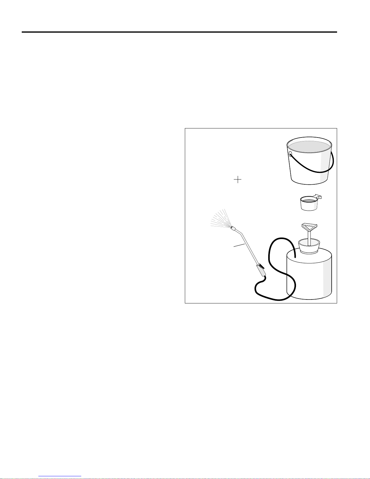
9 BATTERY POWER MODULE
1-1/2 GALLONS
CLEAR WATER
1/4 CUP SODIUM
BICARBONATE
(BAKING SODA)
2 GAL. GARDEN SPRAYER
(1 1/2 GAL. OF WATER)
NON-METAL
WAND
TR008
9.3 MAINTENANCE ___________________________________________________________
Tool List
Insulated wrench, 3/8”
Insulated wrench, 11/32”
Standard Screwdriver
Before charging batteries
Inspect the connector housings of the battery charger
and battery pack for dirt or debris. It is suggested to apply
white lithium grease to both terminals to prevent
corrosion.
Charge the batteries daily after use.
9.4 CLEANING BATTERIES ____________________________________________________
When cleaning the batteries, do not use a water hose
without first spraying with a solution of sodium
bicarbonate (baking soda) and water to neutralize any
acid deposits.
Use of a water hose without first neutralizing any acid,
will move acid from the top of the batteries to another
area of the mower or storage facility where it will attack
the metal structure or the concrete/asphalt floor. After
hosing down the batteries, a residue will be left on the
batteries which is conductive and will contribute to the
discharge of the batteries.
The correct cleaning technique is to spray the top and
sides of the batteries with a solution of sodium
bicarbonate (baking soda) and water. This solution is
best applied with a garden type sprayer equipped with a
non metallic spray wand. The solution should consist of
1/4 cup (59.1 ml) of sodium bicarbonate (baking soda)
mixed with 1-1/2 gallons (5.7 l) of clear water. In addition
to the batteries, special attention should be paid to
metallic components adjacent to the batteries which
should also be sprayed with the sodium bicarbonate
(baking soda) solution.
Allow the solution to sit for at least three minutes; use a
soft bristle brush or cloth to wipe the tops of the batteries
in order to remove any residue that could cause the self
discharge of the battery. Rinse the entire area with low
pressure clear water. Cleaning should take place yearly
or more often under extreme conditions.
44
Figure 9A
Page 45
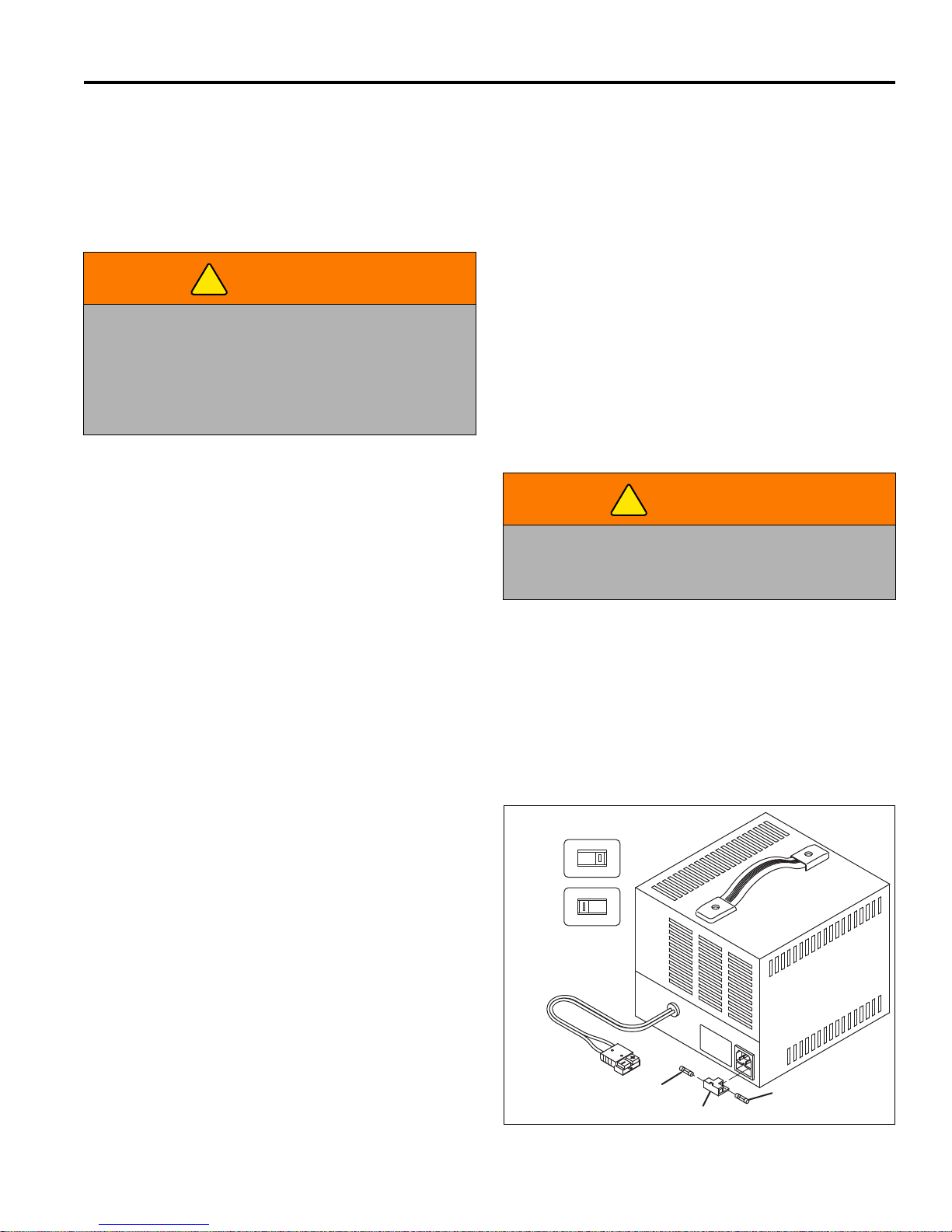
BATTERY POWER MODULE 9
!
!
WA
R
N
ING
- For contin
ued
prote
ction
ag
ainst fire, re
place only w
ith sam
e
size and type fu
se
.
INT
ERAC
TE
R
INC
O
RP
OR
A
TED
M
OD
EL:
BATCH
:
S
ER
IAL NO
:
INP
UT:
1. Connect and di
sconnect batter
y leads o
nly when
supp
ly cord is disc
o
nn
ec
ted or arcing
and b
urning
m
ay re
sult.
2. B
A
TTERY LEAD CO
N
N
ECTIO
N
S - For a batter
y
installed in a
veh
icle, first conne
ct charge
r output
lead to ungrounded batter
y post - not conn
ected to
auto
m
obile chassi
s - in acco
rda
nce w
ith polar
ity
indication, and
th
en opposite
p
olarity lead to
chas
sis a
way
from
b
atter
y; do not co
nne
ct
to
carburetor or fuel
line
s.
D
isconn
ect chassis l
ead
first. F
or batter
y n
ot in
stalled
in a vehicle
, refer to
instru
ction
m
an
ual.
3. Do not over
-charge battery - see instruction
m
anual
4. D
o not smok
e,
strike a m
atch, or cau
se a spar
k in
vicinity of batte
r
y during char
ging.
5. U
se only in a w
e
ll ve
ntilated area.
This equipm
ent e
m
ploys parts, s
uch
as sw
itches and
relays
, that tend to pro
d
uce arcs and spar
ks and
therefore, if used
in a
garage
, locate in a
r
oom
or
enclosure pro
vided for the p
ur
po
se
or not less than 18
inches from the floor.
C
A
U
T
IO
N
- D
O
N
O
T EX
POSE
T
O
R
AIN:
replace
defective cords or w
ires i
mm
ediately.
CAUTIO
N
:
NE PAS
EXP
O
SER
A
LA
PLUIE.
ADVERTISSEM
EN
T
: R
ISQU
E D
E M
ELANG
E
GAZE
AUX
EXPLO
SIF.
LIRE LA NOTICE A
VANT D
'U
TILIS
ER
LE
CHARG
EU
R.
WARNING - RISK OF EXPLOSIVE GAS MIXTURE
115V
230V
Input Voltage Selector
Position
1
Position
2
Spare Fuse
Fuse Holder
Fuse
9.5 BATTERY CHARGER_______________________________________________________
The battery charger is designed to fully charge the
battery pack. Read the instruction manual included with
the charger for proper operating procedure.
Before charging, the following should be observed:
WARNING
Portable chargers should be mounted on a platform
above the ground, or in such a manner as to permit
the maximum air flow underneath and around the
charger. Serious damage to the charger, overheating
and potential for fire may result if the charger does not
have sufficient air flow.
The charging must take place in an area that is well
ventilated and capable of removing the hydrogen gas that
is generated by the charging process. A minimum of five
air exchanges per hour is recommended.
The charging connector components are in good
condition and free from dirt or debris. It is suggested to
apply white lithium grease to both terminals to prevent
corrosion.
The charger connector is fully inserted into the battery
pack receptacle.
The charger connector/cord set is protected from
damage and is located in an area to prevent injury that
may result from personnel running over or tripping over
the cord set.
Install all chargers in accordance with the manufacturers
instructions.
AC Voltage
The charger is equipped with an input voltage selector
switch located on the rear of the charger. Determine what
input voltage is used in your area and set switch
accordingly before connecting AC power cord. This
charger can be used with the following AC input voltages:
100 - 130 V (Set voltage selector to 115 V (Position 1))
200 - 240 V (Set voltage selector to 230 V (Position 2))
NOTE: Charger will operate with either a 50 or 60 Hz
input voltage.
Make certain the AC power cord is equipped with an
appropriate plug for the area you live in. The charger is
equipped with a grounding plug, do not attempt to
defeat its functionality.
WARNING
An ungrounded electrical device may become a
physical hazard that could result in an electrical shock
or electrocution
Note: The AC power cord included with the battery
charger is used with 115 V - 60 Hz (North America) input
voltage only. If you live in an area where 115 V - 60 Hz
input voltage is not used, a new AC power cord must be
purchased locally.
The battery charger should fully charge the battery pack
in approximately 5 hours with 115V AC input voltage.
Battery charging times may exceed 8 hours in areas
where 100V AC input voltage is used.
If the charger is operated in an outdoor location, rain
and sun protection must be provided.
Remove AC power cord from outlet before connecting or
disconnecting battery charger to battery pack.
The charging (DC) cord is equipped with a polarized
connector which fits into a matching receptacle on the
battery pack.
If the charger is not operating correctly, unplug charger
from both the AC outlet and the battery pack and check
the fuse. If a new fuse is required, order part number
4102780 from your Jacobsen Dealer. There is one spare
fuse included in the fuse holder.
45
Page 46
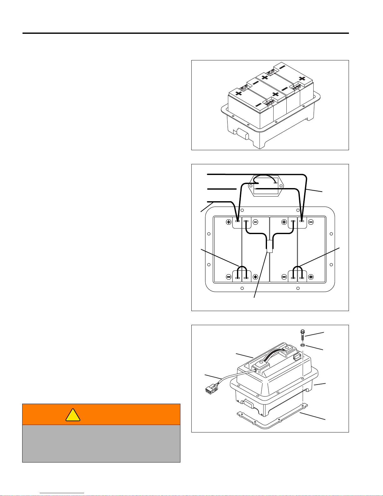
9 BATTERY POWER MODULE
!
P
N
KEY
RD Wire
BK Wire
D
E
E
F
F
Og/Gn Wire
J
K
L
G
F
H
9.6 BATTERY INSTALLATION __________________________________________________
If the batteries have been cleaned and any acid in the
battery tray area neutralized, no corrosion to the
surrounding area should be present. Any corrosion found
should be immediately removed with a putty knife and a
wire brush. The area should be washed with a solution of
sodium bicarbonate (baking soda) and water and
thoroughly dried before priming and painting with a
corrosion resistant paint.
The batteries should be placed into the battery tray as
shown in Figure 9B. Using batteries with the correct
physical size will prevent movement, but will not be tight
enough to cause distortion of the battery case.
Inspect all wires and terminals. Clean any corrosion from
the battery terminals or the wire terminals with a solution
of sodium bicarbonate (baking soda) and brush clean if
required.
Use care to connect the battery wires as shown in Figure
9C and tighten the battery post hardware securely.
Protect the battery terminals and battery wire terminals
with a commercially available protective coating.
Figure 9B
Battery Pack Assembly:
1. Install batteries into battery tray.
2. Fasten fuse cable assembly (D) to battery pack with
screws, lockwashers, and nuts.
3. Fasten two cable jumper wires (E) into their
respective positions.
4. Thread the main cable (F) through the hole in the
side of the battery case lid (G).
5. Attach the main cable (F) to the batteries, and
battery monitor (M).
NOTE: There will be an Orange/Green wire with
insulated 1/4” terminal that is not used on the Eclipse
mowers. Seal end of the wire to prevent short-circuits.
6. Assemble the two halves of the battery case (G)
and (H), with screws (J), flat washers (K), and
battery casing straps (L).
Refer to Section 2.6 for battery specifications.
WARNING
Figure 9C
Aerosol containers of battery terminal protectant must
be used with extreme care. Insulate the metal
container to prevent the metal can from contacting
battery terminals which could result in an explosion.
46
Figure 9D
Page 47
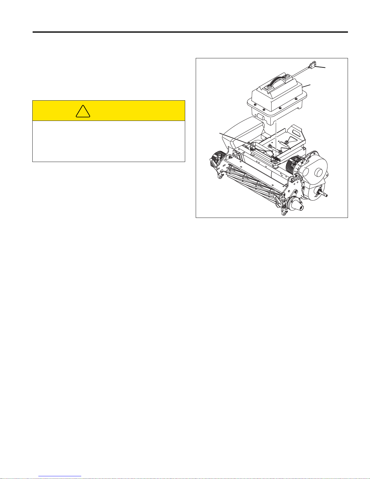
BATTERY POWER MODULE 9
!
A
B
C
9.7 REPLACING BATTERY PACK________________________________________________
The battery pack (A) is designed to be easily lifted out
and replaced. This allows the mower to quickly return to
service should the batteries become discharged or fail.
Additional battery packs are available as an accessory.
See Section 2.7
CAUTION
To prevent injury or property damage, place mower
on kick stand before removing battery pack.
Full battery packs weigh approximately 60 lbs. (27.2
kg) Use proper lifting techniques when moving them.
To remove battery pack:
1. Park mower on a solid, level area.
2. Set parking brake and remove key from switch.
3. Disconnect battery connector (B), place mower on
kickstand.
4. Push and hold battery release latch (C) down and
lift battery pack (A) away from mower.
5. Reverse procedure to install pack. Be sure pack is
completely seated on frame and secure.
Figure 9E
47
Page 48
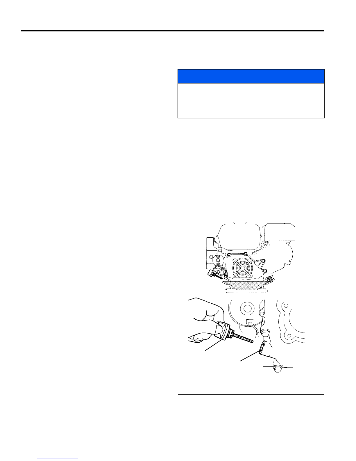
10 GEN-SET POWER MODULE
Upper Oil Level
Oil Filler Cap
10 GEN-SET POWER MODULE
10.1 ENGINE _________________________________________________________________
IMPORTANT: A separate Engine Manual, prepared by
the engine manufacturer, is supplied with the power
module. Read the engine manual carefully until you
are familiar with the operation and maintenance of
the engine. Proper attention to the engine
manufacturer’s directions will assure maximum
service life of the engine. To order replacement
engine manuals contact the engine manufacturer.
The proper break-in of a new engine can make a
considerable difference to the performance and life of the
engine.
The mower is designed to operate and cut most
efficiently at the preset governor setting. Do not
change the engine governor settings or overspeed
the engine.
During the break-in period, Jacobsen recommends the
following:
1. Operate machine modestly for the first 25 hours.
2. Allow the engine to reach operating temperature
before operating at full load.
3. Change the engine oil after the first 20 hours of
operation.
4. Refer to Section 13.2 and Engine Manual for
specific maintenance intervals.
NOTICE
10.2 ENGINE OIL ______________________________________________________________
Check the engine oil at the start of each day, before
starting the engine. If the oil level is low, remove oil filler
cap and add oil as required.
See the engine manufacturer’s Owners’s Manual for
detailed service information.
After adding or changing oil, start and run engine at idle
with all drives disengaged for 30 seconds. Shut engine
off. Wait 30 seconds and check oil level. Add oil to bring
up to FULL mark on dipstick.
Use only SAE 10W30 engine oils with API classification
SG.SF/CC.CD.
48
Figure 10A
Page 49
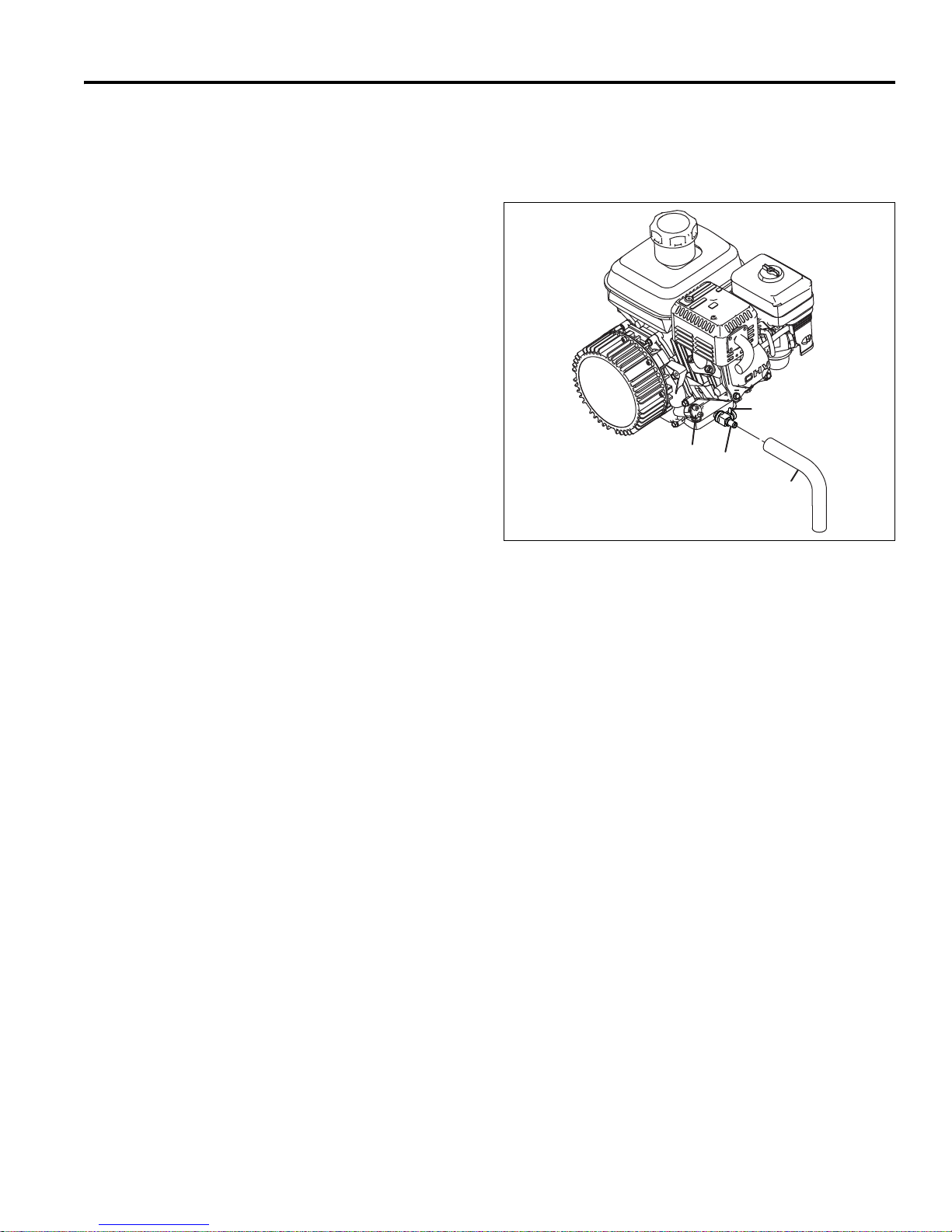
GEN-SET POWER MODULE 10
A
B
C
D
10.3 ENGINE OIL CHANGE ______________________________________________________
Perform initial oil change after the first 20 hours of
operation. Change oil every 100 hours thereafter.
1. To change engine oil, attach a 7/16 in. (11 mm) i.d.
hose (A) to oil drain valve (B). Place other end of
hose into a suitable container.
2. Remove oil fill plug (C).
3. Push drain lever (D) towards rear of mower and
rotate down. Allow engine oil to drain into container.
4. When oil has completely drained, rotate drain lever
(D) up until it latches in the closed position.
5. Remove hose (A) and clean up any spilled oil.
6. Add engine oil until oil level is at full level. See
Figure 10A.
After adding or changing oil, start and run engine at idle
with all drives disengaged for 30 seconds. Shut engine
off. Wait 30 seconds and check oil level. Add oil to bring
up to FULL level.
Use only SAE 10W30 engine oils with API classification
SG.SF/CC.CD.
Figure 10B
10.4 ENGINE SPEED ___________________________________________________________
The engine speed is set at the factory for proper
generator output. However, engine speed should be
checked periodically, and adjusted to 59 volts. An output
voltage greater than 60 volts will cause an alarm to sound
and may cause system damage. Controller will shut
down after 60 seconds if the over voltage condition is not
corrected.
1. Turn the ignition switch to run position. Start the
engine and turn ignition switch to start position.
2. Press either orange button on LCD display until
system voltage screen is on the display.
3. Remove the throttle lever cover.
4. Adjust the engine throttle position until LCD displays
system voltage of 59 volts.
5. Stop the engine and install throttle lever cover.
49
Page 50

10 GEN-SET POWER MODULE
!
10.5 FUEL ____________________________________________________________________
Handle fuel with care - it is highly flammable. Use an
approved container, the spout must fit inside the fuel filler
neck. Avoid using cans and funnels to transfer fuel.
WARNING
Never remove the fuel cap from the fuel tank, or add
fuel, when the engine is running or while the engine is
hot.
Do not smoke when handling fuel. Never fill or drain
the fuel tank indoors.
Do not spill fuel and clean spilled fuel immediately.
Never handle or store fuel containers near an open
flame or any device that may create sparks and ignite
the fuel or fuel vapors.
Be sure to reinstall and tighten fuel cap securely.
• Store fuel according to local, state or federal
ordinances and recommendations from your fuel
supplier.
• Never overfill or allow the tank to become empty.
• Use clean, fresh, regular grade, unleaded gasoline
minimum 86 Octane.
• See engine manual before using oxygenated (blended)
fuel.
• Do not fill above the fuel filler neck.
50
Page 51
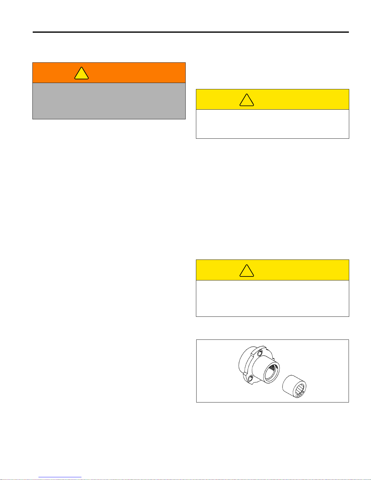
MAINTENANCE 11
!
!
!
11 MAINTENANCE
11.1 GENERAL ________________________________________________________________
e. Keep tires properly inflated (If installed).
WARNING
Before you adjust, clean, or repair this equipment,
always disengage all drives, engage parking brake,
turn power off and disconnect power connector to
prevent serious injury.
1. Adjustment and maintenance should always be
performed by a qualified technician. If proper
adjustments cannot be made, contact an Authorized
Jacobsen Dealer.
2. Inspect the equipment on a regular basis, establish
a maintenance schedule and keep detailed records.
a. Keep the equipment clean.
b. Keep all moving parts properly adjusted and
lubricated.
c. Replace worn or damaged parts before operating
the machine.
d. Keep shields in place and all hardware securely
fastened.
3. Long hair, jewelry or loose fitting clothing may get
tangled in moving parts.
CAUTION
Be careful to prevent entrapment of the hands and
fingers between moving and fixed components of the
machine.
4. Use the illustrations in the Parts Catalog as
reference for the disassembly and reassembly of
components.
5. Recycle or dispose of all hazardous materials
(batteries, lubricants, etc.) according to local, state
or federal regulations.
6. Do not change speed limit settings or overspeed the
drive motors.
7. After servicing reel or traction motor, check to be
sure motor connections are tight.
11.2 TIRES (OPTION) ___________________________________________________________
1. Keep tires properly inflated to prolong tire life. Check
pressure only when the tires are cool.
CAUTION
2. Use an accurate, low pressure tire gauge. 6 - 8 psi
(0.413-0.551 BAR)
11.3 WHEEL BEARING _________________________________________________________
The bearing has the word LOCK and an arrow stamped
on the face. When replacing the bearing, make
absolutely certain that the bearing is being installed in the
proper direction or rotation.
For the Right wheel, install the bearing with the
“LOCK➨" arrow to the Outside of the bearing housing.
For the Left wheel, install the bearing with the “LOCK➨"
arrow to the Inside of the housing.
Unless you have the proper training, tools and
experience, DO NOT attempt to mount a tire on a rim.
Improper mounting can produce an explosion that
may result in serious injury.
Figure 11A
51
Page 52
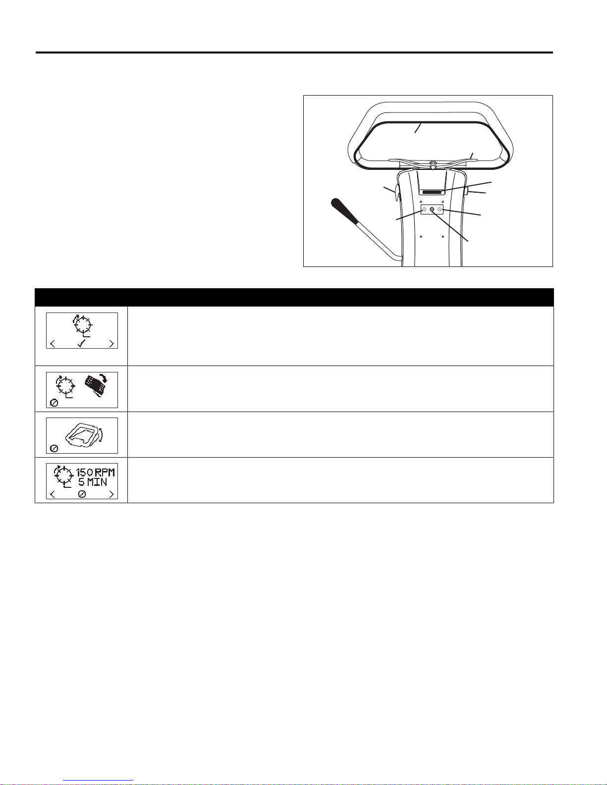
11 MAINTENANCE
A
F
G
H
E
B
C
D
11.4 BACKLAPPING AND GRINDING _____________________________________________
Check for damage to the bedknife and reel blades.
Refer to (Section 6.2).
1. Determine if backlapping or grinding will restore the
proper cutting edge.
2. For optimum performance use a bedknife grinder to
touch-up the blade then reassemble and adjust the
bedknife to the reel as described in (Section 6.2).
Disconnect motor connections whenever turning the
reel by means other than the reel motor. When
tightening, hand tighten motor connections only,
do not use wrenches to tighten motor
connection.
Figure 11B
Backlap Display Description
Backlap Select - Used to switch mower into backlap mode. Start the mower and enter
Maintenance mode. [See Section 4.3]
Use the orange buttons (G or H) until the select backlap screen is on the display. Press the
black button (F) to enter backlap mode.
Engage Reel Switch - To backlap, place reel switch (E) in ON position. If Cancel (Ø) is
selected, display will return to backlap select screen.
Engage Bail - Engage O.P.C. bail (C) and release. Reel motor will begin turning, a slow beeping
(1 every three seconds) alarm will sound and a five minute timer will start. If Cancel (Ø) is
selected, display will return to backlap select screen.
Backlap Reel Speed and Timer Adjust reel speed between 150 to 400 rpm using the orange
buttons (G or H). Press the black button (F) to Cancel (Ø) backlap.
3. Apply lapping compound with a long handle brush
along the entire length of the reel, (180 grit is
recommended, Section 2.7).
4. Continue lapping and at the same time make a fine
adjustment on the reel and bedknife until there is a
uniform clearance along the full length of the cutting
edges.
5. Exit backlap mode by allowing the five minute timer
to end, selecting Cancel (Ø), placing reel switch (E)
in the OFF position, moving the O.P.C. bail (C),
moving the thumb lever (B), or turning key switch
(D) to the OFF position.
6. Turn key switch (D) to off position.
7. Carefully and thoroughly remove all lapping
compound from reel and bedknife before running
the reel in forward direction.
52
Page 53
MAINTENANCE 11
!
!
11.5 STORAGE ________________________________________________________________
General
1. Wash the mower thoroughly and lubricate. Repair
and paint damaged or exposed metal.
2. Inspect the mower, tighten all hardware, replace
worn or damaged components.
3. Clean the tires thoroughly and store the tractor on
the kickstand so the load is off the tires. The front
roller should be resting on a wood board.
4. Keep the machine and all its accessories clean, dry
and protected from the elements during storage.
Never store equipment near an open flame.
5. Wash the reel and bedknife thoroughly, then repair
and paint any damaged or exposed metal.
6. Lubricate all fittings and friction points.
7. Backlap the reels then back the reel away from the
bedknife. Apply a light coat of rust preventative oil to
the sharpened edges of the reel and bedknife.
CAUTION
To prevent personal injury and damage to the cutting
edges, handle the reel with extreme care.
Battery Power Module:
During periods of storage, the batteries will need
attention to keep them maintained and prevent
discharge.
In high temperatures the chemical reaction is faster, while
low temperatures cause the chemical reaction to slow
down. If a fully charged battery is allowed to sit unused, it
will slowly self discharge. When the battery charge level
falls to 80% of its full charge, it should be recharged.
to slow self discharge. The batteries should be tested or
recharged at thirty day intervals.
Battery Power Module After Storage
1. Fully charge the batteries.
2. Make certain that the tires are properly inflated.
3. Remove all oil from the reels and bedknife. Adjust
bedknife and cutting height.
Gen-Set Power Module:
1. While the engine is warm, remove drain plug, drain
the oil from the crankcase. Install drain plug and refill
with fresh oil. Torque drain plug to 22 ft. lb. (30 Nm).
2. Clean exterior of engine. Paint the exposed metal or
apply a light coat of rust preventative oil.
3. To prevent the build-up of gum residues and vanish
films, fill the tank with stabilized fuel. Use an antioxidant fuel conditioner, such STA-BIL®. Read and
follow the instructions on the container.
4. Operate the engine for about 5 minutes to distribute
the treated fuel. Stop the engine, close the fuel
shut-off valve and let the engine cool. Drain fuel.
5. Remove the spark plug and pour about one ounce
of SAE 30 oil into the cylinder. Crank engine slowly
by hand to distribute oil over the cylinder wall.
Replace the spark plug.
6. Pull the starter rope slowly until resistance is felt.
Continue pulling until the notch on the starter pulley
aligns with the hole on the recoil starter. At this
point, the intake and exhaust valves are closed.
Gen-Set Power Module After Storage
1. Check or service the fuel filter and air cleaner.
If a battery is allowed to fully discharge and is left in a
discharged state, sulfation takes place on and within the
plates. This condition is not reversible and will cause
permanent damage to the battery. In order to prevent
damage, the battery should be recharged.
In winter conditions, the battery must be fully charged to
prevent the possibility of freezing. A fully charged battery
will not freeze in the most severe of winter climates.
Although the chemical reaction is slowed in cold
temperatures, the battery must be stored fully charged,
and disconnected from any circuit that could discharge
the battery. Disconnect the charging plug from the mower
power connector. The batteries must be cleaned and all
deposits neutralized and removed from the battery case
2. Check oil level in the engine crankcase.
3. Fill the fuel tank with fresh fuel. Open fuel shut off
valve.
4. Remove all oil from the cutting edges. Readjust reelto-bedknife and cutting height.
5. Start the engine and allow enough time for the
engine to become properly warmed and lubricated.
WARNING
Never operate the engine without proper ventilation;
exhaust fumes can be fatal if inhaled.
53
Page 54

12 TROUBLESHOOTING
12 TROUBLESHOOTING
12.1 GENERAL________________________________________________________________
The troubleshooting chart below lists basic problems that may occur during start-up and operation. For more detailed
information, contact your area Jacobsen Dealer.
Symptoms Possible Causes Action
Unit does not have
power
Engine will not
start.
Engine hard to start
or runs poorly,
looses power or
stalls.
Mower does not
react properly to
O.P.C. Lever
Reel does not cut,
or cuts unevenly
1. Power Connector Disconnected 1. Connect Power Connector
2. Batteries Discharged 2. Fully charge battery pack
3. Engine not running 3. Start engine before attempting to energize unit
4. 50 Amp fuse blown 4. Open battery tray and check fuse. Replace if
required
5. 30 Amp fuse blown 5. Remove handle cover and check fuse. Replace if
required
6. Defective Battery 6. Perform load test, replace batteries as needed
7. O.P.C. bail engaged 7. Disengage bail and restart
1. Choke in wrong position 1. See Engine Manual
2. Empty fuel tank or dirty fuel 2. Drain and refill fuel tank with fresh, clean fuel
3. Fuel Shut-off valve closed 3. Open fuel shut-off valve
4. Engine / Spark Plug 4. See Engine Manual
5. Engine switch off 5. Turn engine switch to On
1. Choke in wrong position 1. See Engine Manual
2. Dirty or incorrect fuel 2. Refill with proper grade, clean fuel
3. Loose Wiring 3. Check spark plug wire
4. Air intake plugged 4. Clean air intake and air cleaner
5. Vent in fuel cap plugged 5. Clean fuel cap
1. Power switch not on 1. Follow proper start-up procedure
2. Parking brake engaged 2. Disengage parking brake
3. Reel switch in off position 3. Turn reel switch on
4. Broken Belt 4. Check and replace belts as needed
5. Bail lever not properly calibrated 5. Calibrate bail lever
6. Traction motor fault 6. Check LCD display, service traction motor
1. Reel to bedknife not adjusted 1. Adjust Reel to Bedknife
2. Reel switch in off position 2. Turn reel switch on
3. Reel motor fault 3. Check LCD display, service reel motor
4. Low battery charge 4. Fully charge battery pack
5. Over Voltage condition 5. Adjust generator output
54
Page 55

MAINTENANCE & LUBRICATION CHARTS 13
!
13 MAINTENANCE & LUBRIC ATION CHARTS
13.1 GENERAL ________________________________________________________________
The mower was designed for minimum lubrication. Over
greasing will produce high loads on the bearings;
thereby reducing the performance of the machine. Over
greasing reel bearings may also damage the electric
motor; voiding the warranty.
All maintenance intervals must be performed more
frequently when operating in extremely dusty conditions.
2. Lubricate with grease that meets or exceeds NLGI
Grade 2 LB specifications. Apply grease with a
manual grease gun and fill slowly until grease
begins to seep out. Do not use compressed air.
3. For smooth operation of pivot points and other
friction points, apply several drops of SAE 30 oil
every 50 hours or as required.
4. Do not over grease reel bearing (L2). Damage to
WARNING
Before you clean, adjust, or repair this equipment,
disengage all drives, engage parking brake, turn
power off and disconnect power connector to prevent
injuries.
the motor may result. This damage is not covered
under the warranty.
5. To lubricate point (L4), remove L.H. transport wheel
and mounting bracket (E) to gain access to fitting.
Turn the traction drum if pulley (F) is blocking the
fitting then insert grease gun through hole and
carefully apply grease.
1. Always clean grease fittings before and after
lubrication.
6. To lubricate points (L7), remove transport wheel, nut
(A) from end of shaft and pull wheel hub (D) off.
Remove collar (B) and bushing (C) then pack
bearing with lithium grease.
13.2 MAINTENANCE CHART_____________________________________________________
Recommended Service and Lubrication Intervals
Every
20
Hours
IC
IR* R II
● Charge Batteries
Belt Tension
Air Cleaner
▼ Combustion Chamber
▼ Engine Oil
▼ Fuel Line
▼ Fuel Strainer
▼ Spark Plug
▼ Valve Clearance
Grease Locations
L1 - L5
L6-L7
Every
3-4
Hours
AR I C
A - Adjust C - Clean I - Inspect L- Lubricate R - Replace AR - As Required
* Indicates initial service for new machines.
I Manual grease gun with NLGI Grade 2 (Service Class LB).
II Engine Oil - See 10.2
Every
50
Hours
Every
100
Hours
C
A/R
LLI
Every
250
Hours
C
A
Yearly Lubricant
I-A
R - 2yrs
L I
Type
● Battery Power Module
▼ Gen-Set Power Module
55
Page 56
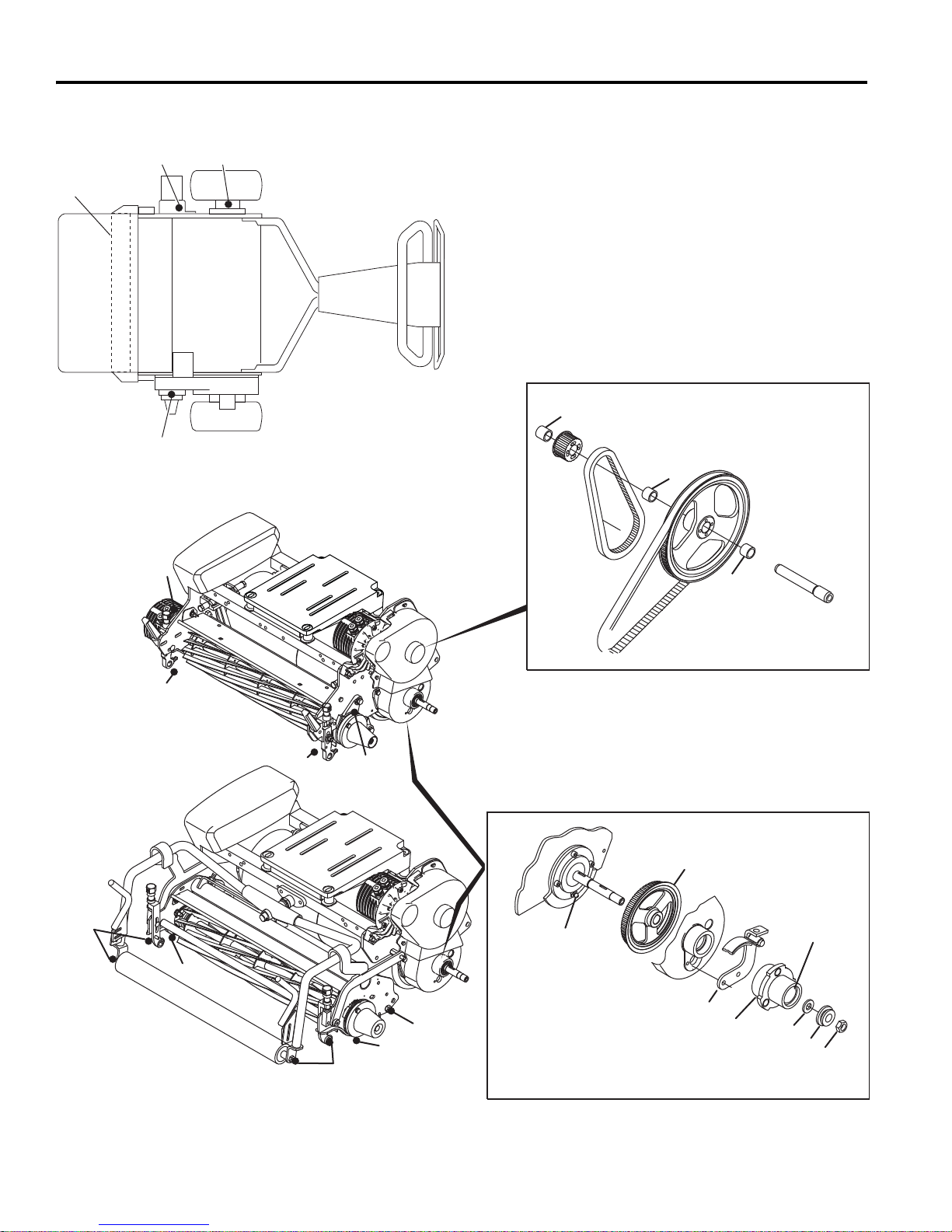
13 MAINTENANCE & LUBRICATION CHARTS
F
C
D
B
A
L
4
L
6
L
6
L
7
E
●
●
●
●
●
L
3
L
L
5
2
L
1
L
L
5
L
5
2
L
2
L
1
L
1
L
1
L
1
L
1
L1 - Reel Roller Bearing
L
2 - Reel Motor Bearing Housing
L
3 - Right Side Traction Drum Bearing Housing
L
4 - Left Side Traction Drum Bearing Housing
L
5 - Reel Bearing Housing
L
6 - Pulley Shaft Bearing
L
7 - Hub
Wheel Hub Assembly
Pulley Shaft Assembly
13.3 LUBRICATION CHART _____________________________________________________
56
Page 57

PARTS CATALOG 14
14 PARTS CATALOG
14.1 HOW TO USE THE PARTS CATALOG _________________________________________
Abbreviations
N/S - Not serviced separately, can only be obtained
by ordering main component or kit.
AR -Variable quantity or measurement is required
to obtain correct adjustment.
Indented Items
Indented items indicate component parts that are
included as part of an assembly or another component.
These parts can be ordered separately or as part of the
main component.
Symbols such as ●, next to the item number,
indicate that a note exists which contain additional
information important in ordering that part.
Item Part No. Qty Description Serial Numbers/Notes
● 1 123456 1 Mount, Valve Indicates a piece part
2 789012 1 Valve, Lift Includes Items 2 and 3
3 345678 1 • Handle Serviced part included with Item 2
4 N/S 1 • Seal Kit Non serviced part included with Item 2
5 901234 1 Screw, 1/4-20 x 2” Hex Head
14.2 TO ORDER PARTS _________________________________________________________
1. Write your full name and complete address on the
order.
2. Explain where and how to make shipment.
3. Give product number, name and serial number that is
stamped on the name plate or serial plate of your
product.
4. Order by the quantity desired, the part number, and
description of the part as given in the parts list.
5. Send or bring the order to an authorized Jacobsen
Distributor.
6. Inspect all shipments on receipt. If any parts are damaged or missing, file a claim with the carrier before
accepting.
7. Do not return material without a letter of explanation,
listing the parts being returned. Transportation
charges must be prepaid.
14.3 PARTS CATALOG TABLE OF CONTENTS______________________________________
1.1..............................Handle Covers.............................................................................................................................................. 58
2.1..............................Handle Assembly......................................................................................................................................... 60
3.1..............................Handle to Frame Mount............................................................................................................................... 62
4.1..............................Power Module Mounting Plate.................................................................................................................... 64
5.1..............................Frame ............................................................................................................................................................ 66
6.1..............................Lower Unit .................................................................................................................................................... 68
7.1..............................Reel ............................................................................................................................................................... 70
8.1.............................. Grass Shield and Roller Brackets .............................................................................................................. 72
9.1..............................Floating Head Reel Connection.................................................................................................................. 74
10.1............................Outer Reel Assembly................................................................................................................................... 76
11.1............................Inner Reel Assembly.................................................................................................................................... 78
12.1............................Differential and Rollers................................................................................................................................ 80
13.1............................Parking Brake and Wheels.......................................................................................................................... 82
14.1............................Belts and Drive Motors................................................................................................................................ 84
15.1............................Harness Routing .......................................................................................................................................... 86
16.1............................Genset Power Source.................................................................................................................................. 88
17.1............................Battery Power Source.................................................................................................................................. 90
18.1............................Battery Case ................................................................................................................................................. 92
19.1............................Electrical Schematic .................................................................................................................................... 94
57
Page 58
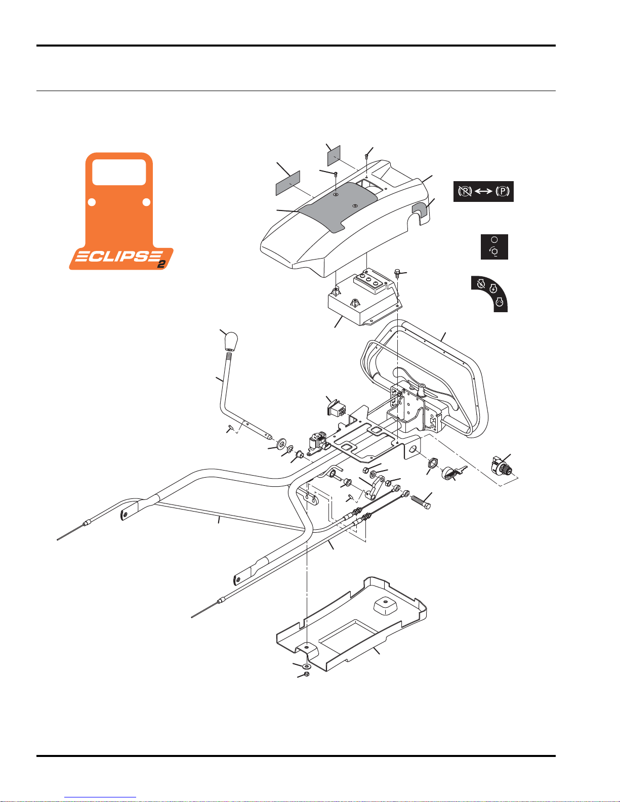
®
DRY ERASE MARKER ONLY
1
2
3
4
5
6
6
29
7
8
9
9
10
11
12
13
14
15
16
17
18
19
20
21
21
22
22
23
23
24
24
25
25
26
27
28
4265172
4265171
4265170
ECLIPSE
2
1.1 Handle Covers
Serial No. All
58
Page 59

ECLIPSE
Item Par t No. Qty. Description Serial Numbers/Notes
1
2 4254050 1 Control Lever
3 4127340 1 Knob
4 453017 1 Flat Washer, 1/2
5 454025 AR Spring Washer, 1/2
6 366708 2 Bearing, Flanged
7 461381 1 Roll Pin, 3/16 x 13/16”
8 2000067 1 Lever, Brake Cable
9 443110 2 Nut, 3/8-16 Hex
10 446142 1 Lockwasher, 3/8 Heavy
11 400268 1 Screw, 3/8-16 x 1-3/4” Hex Head
12 4258791 1 Cable, 34-1/2” Brake
12 4258791 1 Cable, 34-1/2” Brake
12 4258830 1 Cable, 38-1/2” Brake
13 4258830 1 Cable, 38-1/2” Brake
13 4258790 1 Cable, 40-1/2” Brake
14 4253551 1 Controller, MCU REFERENCE U5, See 19.1
15 409807 4 Screw, 1/4-20 x 1/2” Thread Cutting
16 4165020 1 Key Switch REFERENCE SW2, See 19.1
17 4131618 1 • Key
18 N/S 1 • Nut, Face
19 4130132 1 Switch, Rocker REFERENCE SW1, See 19.1
20 4253330 1 Cover, Upper Console
21 4260810 1 Decal, Eclipse 2
22 4265172 1 Decal, Key Switch
23 4265171 1 Decal, Reel
24 4265170 1 Decal, Parking Brake
25 402056 4 Screw, #8-32 x 3/8” Slotted
26 4253310 1 Cover, Lower Console
27 445770 2 Nut, 1/4-20 Nylon Insert
28 452004 2 Flat Washer, 1/4
29 461181 1 Groove Pin, 3/16 x 3/4”
REF 1 Handle Assembly See 2.1
Eclipse
Eclipse
Eclipse
Eclipse
Eclipse
118, 118F Left Side
2
122, 122F Left Side
2
126 Left Side
2
118, 118F Right Side
2
122, 122F, 126 Right Side
2
2
> Change from previous revision
59
Page 60
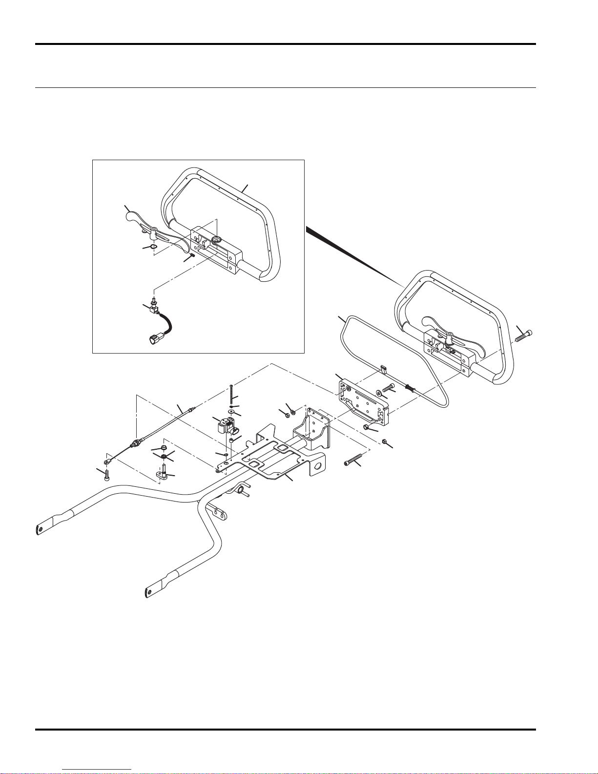
ECLIPSE
2
2.1 Handle Assembly
11
10
9
12
Serial No. All
8
7
13
16
19
15
18
17
21
20
22
23
24
25
2
14
3
4
6
5
6
26
1
60
Page 61

ECLIPSE
Item Par t No. Qty. Description Serial Numbers/Notes
1
2 4136328 1 Plate, Tilt
3 434029 4 Screw, 1/4-20 x 1” Hex Socket
4 453023 4 Flat Washer, 1/4
5 446130 4 Lockwasher, 1/4 Heavy
6 443102 6 Nut, 1/4-20 Hex
7 4136325 1 Bail
8 4147696 1 Handle, Overmolded Includes Decal
9 4260432 1 Hand Throttle Potentiometer REFERENCE R1, See 19.1
10 454020 1 Spring Washer, 7/16
11 4137303 1 Plate, Throttle
12 422504 1 Set Screw, #10-32 x 3/8”
13 4128933 4 Screw, 5/16-18 x 1-1/2” Hex Socket
14 444718 4 Locknut, 5/16-18 Hex Center
15 4256692 1 Cable, OPC
16 434031 1 Screw, 1/4-20 x 3/4” Hex Socket Nylon Patch
17 4156781 1 Lever, Bail
18 4196280 1 Spring, Torsion
19 364154 1 Bushing
20 458001 1 Retaining Ring, 3/8 Truarc
21 4145428 1 Switch, Rotary REFERENCE R2, See 19.1
22 402022 2 Screw, #6-32 x 2” Slotted Round
23 446106 2 Lockwasher, #6
24 453005 2 Flat Washer, #6
25 4136366 2 Spacer, 3/8 x 5/16
26 434054 2 Screw, 1/4-20 x 1-3/4” Hex Socketv
4256578 1 Handle
2
> Change from previous revision
61
Page 62
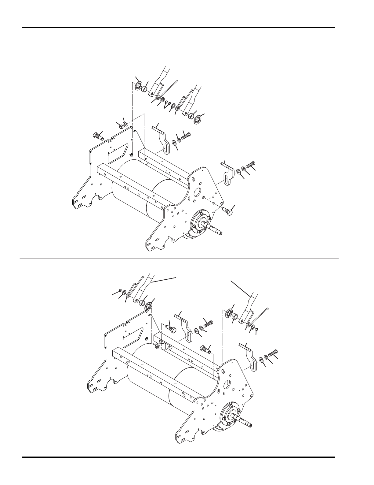
1
1
2
2
3
3
4
5
6
7
8
8
9
9
10
10
11
11
12
12
1
1
2
2
3
3
4
5
6
7
8
8
9
10
10
11
11
12
12
13
Eclipse
2
118 and 118F
63334 63343
63335 63344
63336 63345
63337 63346
Eclipse
2
122, 122F, and 126
63338 63347
63339 63348
63340 63349
63341 63350
63342 63351
Handle Assembly
12
ECLIPSE
2
3.1 Handle to Frame Mount
Serial No. All
62
Page 63

ECLIPSE
Item Par t No. Qty. Description Serial Numbers/Notes
1
2 447224 2 Lockwasher, 5/8 Internal Tooth
3 443828 2 Nut, 5/8-18 Hex Jam
4 4257813 1 Handle Stop, Right Side
5 4257814 1 Handle Stop, Left Side
6 2809900 1 Torsion Spring, Handle
6 2809900 1 Torsion Spring, Handle
7 2809901 1 Torsion Spring, Handle
7 2809901 1 Torsion Spring, Handle
8 455012 2 Flat Washer, 1/2
9 456006 2 Retaining Ring, 1/2” Truarc
10 400286 2 Screw, 3/8-16 x 2-3/4” Hex Head
10 400274 2 Screw, 3/8-16 x 2-1/2” Hex Head
11 446142 2 Lockwasher, 3/8 Heavy
12 453011 4 Flat Washer, 3/8
12 453011 2 Flat Washer, 3/8
13 445808 2 Nut, 3/8-16 Hex Nylock
2811559 2 Bolt, Handle Mount
Eclipse
Eclipse
Eclipse
Eclipse
Eclipse
Eclipse
Eclipse
Eclipse
Eclipse
118, 118F Left Side
2
122, 122F, 126 Right Side
2
118, 118F Right Side
2
122, 122F, 126 Left Side
2
118, 118F
2
122, 122F, 126
2
118, 118F
2
122, 122F, 126
2
118, 118F Only
2
2
> Change from previous revision
63
Page 64
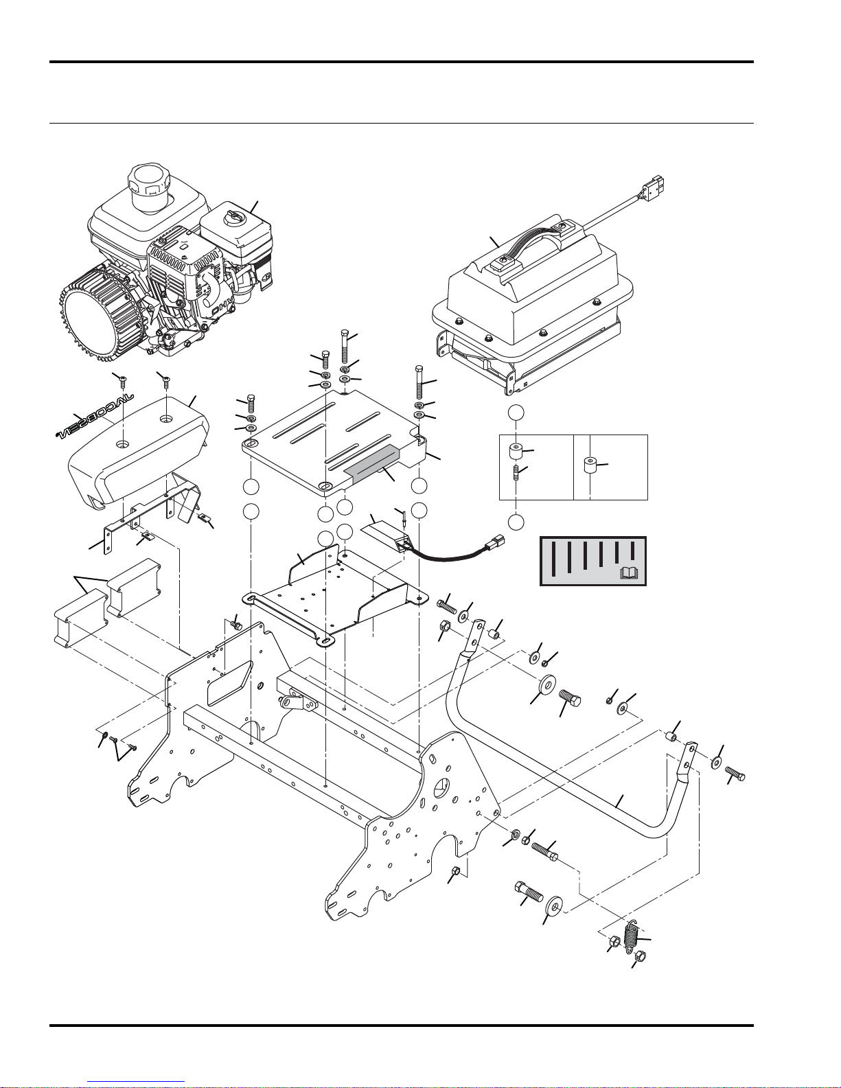
1
2
3
4
37
5
5
6
6
7
8
8
9
9
10
10
10
10
11
12
13
19
20
15
16
16
16
16
17
36
12
4172240
14
18
A
B
A
B
A
B
A
B
A
B
21
Gen-Set Battery
22
23
23
24
24
24
24
25
25
26
26
27
28
28
29
30
31
31
32
33
33
34
35
ECLIPSE
2
4.1 Power Module Mounting Plate
Serial No. All
Fixed Head Frame Shown. Floating Head Similar
64
Page 65

ECLIPSE
Item Part No. Qty. Description Serial Numbers/Notes
2
1
2 63306 1 Battery Power Module See 20.1
3 4253190 2 Controller, Motor REFERENCE U1, U2, See 19.1
4 800271 8 Screw, #10-24 x 1/2” Pan Head
5 404016 2 Screw, 1/4-20 x 5/8” Truss Head
6 445245 2 Tinnerman Nut, 1/4-20
7 4253595 1 Mount, Power Module
8 400186 2 Screw, 5/16-18 x 7/8” Hex Head Gen-Set Power Module Only
8 400198 2 Screw, 5/16-18 x 2-1/4” Hex Head Battery Power Module Only
9 400196 2 Screw, 5/16-18 x 2” Hex Head Gen-Set Power Module Only
9 400204 2 Screw, 5/16-18 x 3-1/2” Hex Head Battery Power Module Only
10 446136 4 Lockwasher, 5/16 Battery Power Module Only
11 409807 2 Screw, 1/4-20 x 1/2” Thread Cutting
12 4193060 1 Decal, Front Roller Weight
13 4258590 1 Cover, Motor Controller
14 4255550 4 Female Iso Mount Gen-Set Power Module Only
15 4259130 1 Bracket, Controller Cover
16 453009 4 Flat Washer, 5/16
17 4257467 1 Plate, Power Module Mounting
18 4255551 4 Stud, Iso-Mount Gen-Set Power Module Only
19 4265710 1 Resistor, Ceramic REFERENCE R3, See 19.1
20 400058 2 Pop Rivet, 3/16 x 1/2”
21 361139 4 Spacer Battery Power Module Only
22 4257455 1 Kickstand, 18”
22 4247755 1 Kickstand, 22”
22 4257770 1 Kickstand, 26” Used on 63342 and 63351
23 400190 2 Screw, 5/16-18 x 1-1/4” Hex Head
24 452006 4 Flat Washer, 5/16
25 366715 2 Spacer
26 444718 2 Locknut, 5/16-18 Hex Center
27 400268 1 Screw, 3/8-16 x 1-3/4” Hex Head
28 443810 2 Nut, 3/8-16 Hex Jam
29 446142 1 Lockwasher, 3/8 Heavy
30 400410 1 Screw, 1/2-13 x 1-3/4” Hex Head
31 344132 2 Washer, 1/2
32 443118 1 Nut, 1/2-13 Hex
33 444758 2 Locknut, 1/2-13 Hex Center
34 364164 1 Spring, Extension
35 400404 1 Screw, 1/2-13 x 1” Hex Head
36 4264210 1 Decal, Jacobsen
37 306998 2 Lockwasher, #10 Int/Ext Tooth
63305 1 Gen-Set Power Module See 19.1
Used on 63334, 63335, 63336,
63337, 63343, 63344, 63345, and
63346
Used on 63338, 63339, 63340,
63341, 63347, 63348, 63349, and
63350
> Change from previous revision
65
Page 66
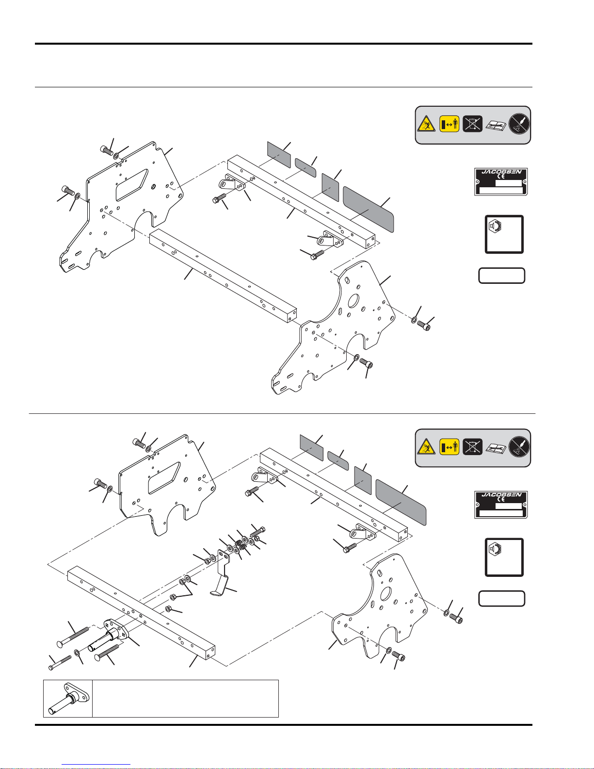
96
dB
L
WA
Manufactured under one or more
of the following U.S. patents:
xxxxxxx xxxxxxx xxxxxxx
xxxxxxx xxxxxxx xxxxxxx
CHARLOTTE, NC
YEAR OF
PRODUCTION:
MADE IN U.S.A.
®
A Textron Company
96
dB
L
WA
Manufactured under one or more
of the following U.S. patents:
xxxxxxx xxxxxxx xxxxxxx
xxxxxxx xxxxxxx xxxxxxx
CHARLOTTE, NC
YEAR OF
PRODUCTION:
MADE IN U.S.A.
®
A Textron Company
1
1
2
2
3
3
3
3
4
4
4
4
4
4
4
4
5
5
5
5
5
5
5
5
6
6
6
6
7
7
7
7
8
8
8
8
9
9
9
9
10
10
10
10
11
11
11
11
12
13
14
15
If 2 Bolt Spindle Mount is installed, order
Spindle Mount Kit 4273830 (122F), or
4273831 (118F).
16
16
16
17
18
19
19
19
19
19
19
19
20
21
21
Eclipse2 118, 122 and 126
63334 63343
63335 63344
63338 63347
63339 63348
63342 63351
Eclipse
2
118F and 122F
63336 63345
63337 63346
63340 63349
63341 63350
ECLIPSE
2
5.1 Frame
Serial No. All
66
Page 67

ECLIPSE
Item Part No. Qty. Description Serial Numbers/Notes
1
4253156 1 Frame, L.H. Side Fixed Head
1 4253154 1 Frame, L.H. Side Floating Head
2 4253155 1 Frame, R.H. Side Fixed Head
2 4253157 1 Frame, R.H. Side Floating Head
3 4257453 2 18” Crossbar
3 4247754 2 22” Crossbar
3 4257470 2 26” Crossbar
4 434030 8 Screw, 3/8-16 x 7/8” Hex Socket
5 64163-04 8 Flat Washer, 3/8
6 4127931 1 Decal, Patent
7 4117466 1 Decal, 96 dBA Noise
8 4169640 1 Decal, Danger
9 REF 1 Serial Plate
10 800710 2 Screw, 5/16-18 x 1” Hex Flange
11 4258190 2 Bracket, Handle Mount
12 400192 1 Screw, 5/16-18 x 1-1/2” Hex Head
13 441672 1 Carriage Bolt, 5/16-18 x 2-1/2”
14 441688 1 Carriage Bolt, 5/16-18 x 3-1/2”
15 4273518 1 Spindle Mount
16 548911 5 Nut, 5/16-18 Hex Flange
17 445802 1 Nut, 5/16-18 Nylon Insert Hex
18 400200 2 Screw, 5/16-18 x 2-1/2” Hex Head
19 453009 8 Flat Washer, 5/16
20 4255870 1 Limit Bracket
21 332844 2 Spring, Compression
Eclipse
Eclipse
Eclipse
Eclipse
Eclipse
Eclipse
Eclipse
Eclipse
Eclipse
Eclipse
Eclipse
Eclipse
Eclipse
Eclipse
Eclipse
Eclipse
Eclipse
Eclipse
Eclipse
118, 122, and 126
2
118F and 122F
2
118, 122, and 126
2
118F and 122F
2
118 and 118F
2
118, 122, and 126
2
126
2
122, 122F, and 126
2
122, 122F, and 126
2
118F and 122F Only
2
118F and 122F Only
2
118F and 122F Only
2
118F and 122F Only
2
118F and 122F Only
2
118F and 122F Only
2
118F and 122F Only
2
118F and 122F Only
2
118F and 122F Only
2
118F and 122F Only
2
2
> Change from previous revision
67
Page 68
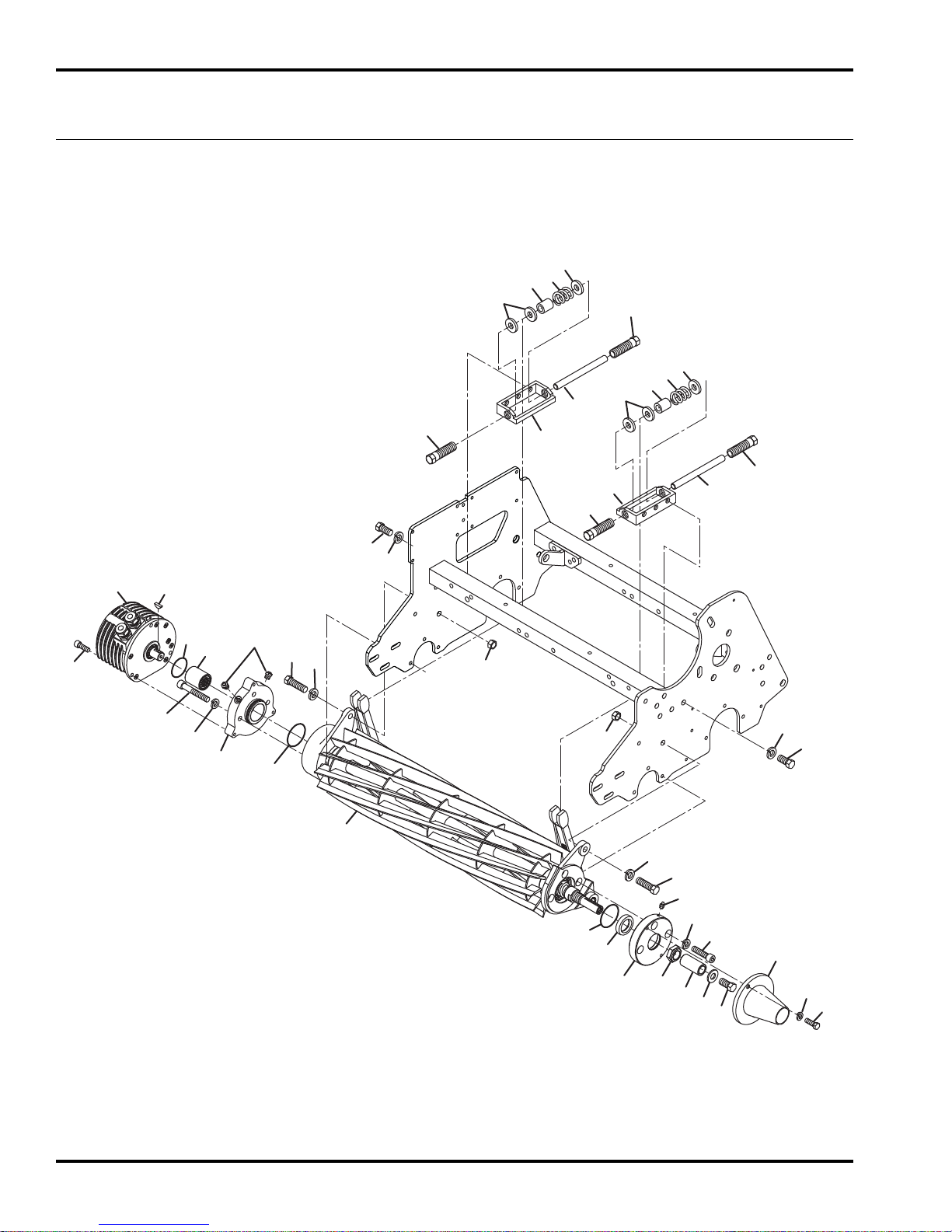
ECLIPSE
2
6.1 Lower Unit
Fixed Head Units
Serial No. 63334 - All
Serial No. 63335 - All
Serial No. 63338 - All
Serial No. 63339 - All
6
Serial No. 63342 - All
Serial No. 63343 - All
Serial No. 63344 - All
Serial No. 63347 - All
7
9
8
7
10
6
7
9
8
7
Serial No. 63348 - All
Serial No. 63351 - All
5
6
5
10
6
31
29 30
26
13
15
27
24
25
13
4
3
2
3
28
28
3
4
1
3
2
16
15
13
12
11
17
18
19
14
20
21
23
22
68
Page 69

ECLIPSE
Item Part No. Qty. Description Serial Numbers/Notes
2
1
2 400264 2 Screw, 3/8-16 x 1-1/4” Hex Head
3 446142 8 Lockwasher, 3/8 Heavy
4 400258 6 Screw, 3/8-16 x 3/4” Hex Head
5 3001610 2 Block, Bedknife Adjuster
6 366726 4 Bolt, 5/8-11 Special
7 366653 6 Spacer, 7/8 x 3/8 x 1/8”
8 367512 2 Spacer, 5/8 x 3/8 x 3/4”
9 366709 2 Spring
10 366727 2 Rod
11 4179780 1 Seal Carrier
12 366648 1 Grease Seal
13 4104720 3 O-Ring
14 434036 3 Screw, 5/16-18 x 1-1/4” Hex Socket
15 446136 6 Lockwasher, 5/16 Heavy
16 471214 1 Grease Fitting, 1/4-20 Straight
17 367029 1 Nut, 3/4-16 Nylock Hex Jam Nut
18 367164 1 Spacer, Reel Shaft
19 453011 1 Flat Washer, 3/8
20 400294 1 Screw, 3/8-24 x 3/4” Hex Head
21 557775 1 Cover, Reel Shaft
22 400108 2 Screw, 1/4-20 x 3/4” Hex Head
23 446130 2 Lockwasher, 1/4 Heavy
24 4167541 1 Adapter, Motor
25 471242 2 Grease Fitting, Relief
26 434049 3 Screw, 5/16-18 x 2” Hex Socket
27 2812384 1 Coupler, Motor
28 443110 2 Nut, 3/8-16 Hex
29 4261470 1 Motor, Brushless Bi-Directional Reference M1, See 19.1
30 463029 1 Key, Woodruff
31 434028 3 Screw, 1/4-20 x 3/4” Hex Socket
REF 1 Reel and Bedknife Assembly See 7.1
> Change from previous revision
69
Page 70
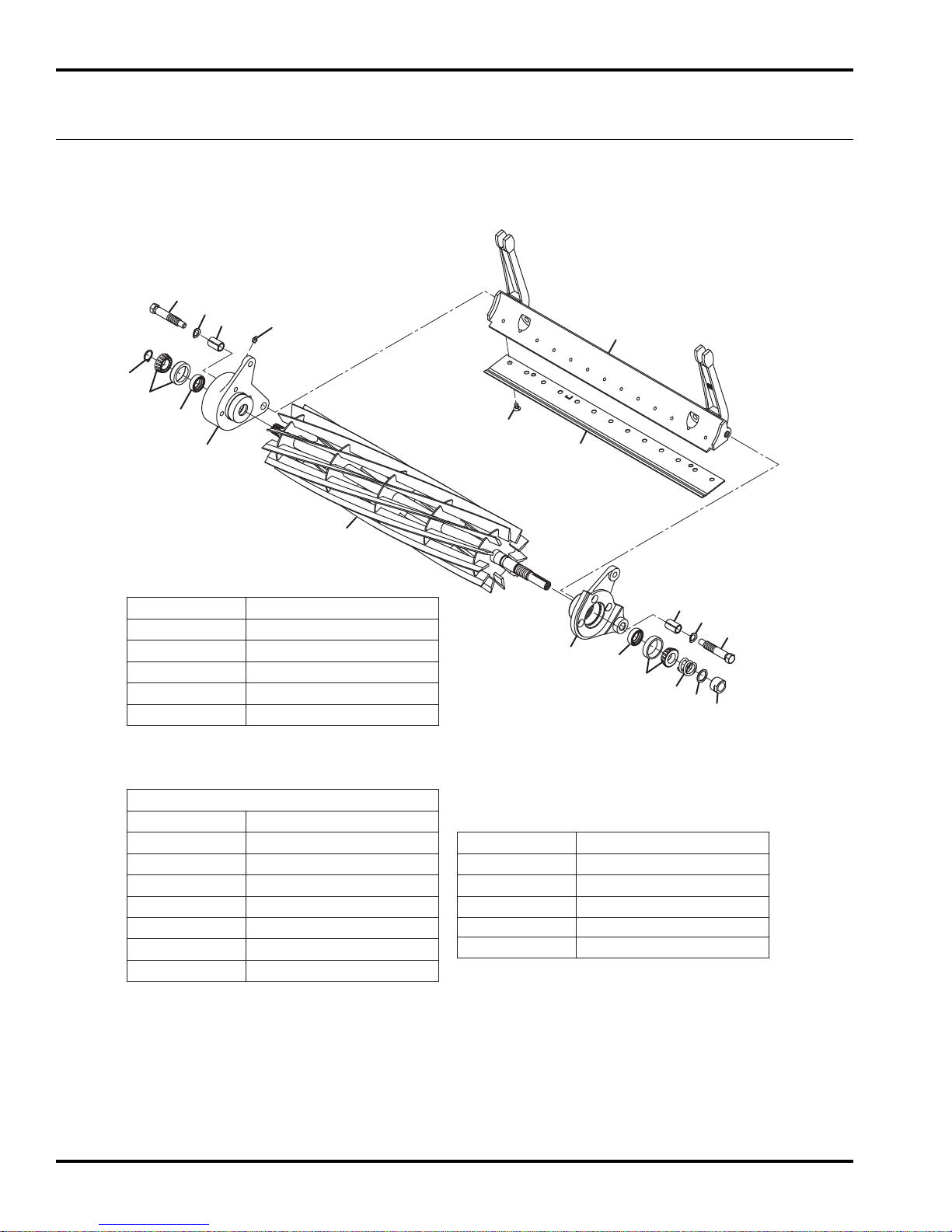
ECLIPSE
7.1 Reel
Fixed Head Units
11
9
2
15
7
16
6
Serial No. 63334 - All
Serial No. 63335 - All
Serial No. 63338 - All
Serial No. 63339 - All
8
10
Serial No. 63342 - All
Serial No. 63343 - All
Serial No. 63344 - All
Serial No. 63347 - All
17
Serial No. 63348 - All
Serial No. 63351 - All
19
18
1
Reels
Part Number Description
4170202 18” 11 Blade Reel
4225502 18” 15 Blade Reel
4172945 22” 11 Blade Reel
4223946 22” 15 Blade Reel
4170203 26” 7 Blade Reel
Standard Style Bedknives
(Secured with screws)
Part Number Description
5000098 18” Low Profile
● 5002888 18” Super Tournament
4234901 18” Championship
503478 22” Low Profile
503477 22” High Profile
● 5002887 22” Super Tournament
4234900 22” Championship
● 5000141 26” Heavy Section
4
16
15
2
3
5
12
13
14
Optional MagKnife Bedknives
Part Number Description
4131005 22” Medium Section
4131369 22” High Profile
4131001 22” Low Profile
4131370 22” Tournament
4131003 22” Super Tournament
● Standard Bedknife
70
Page 71

ECLIPSE
Item Part No. Qty. Description Serial Numbers/Notes
See Chart 1 Reel
1
2 4105281 1 Bearing Housing
3 366650 1 • Grease Seal
4 545940 1 • Bushing
5 500534 1 • Bearing Cup and Cone
6 4179720 1 Bearing Housing
7 366650 1 • Seal
8 545940 1 • Bushing
9 500534 1 • Bearing Cup and Cone
10 4128725 1 • Grease Fitting
11 458013 1 Snap Ring
12 5002151 1 Spring
13 304745 1 Washer
14 364900 1 Nut, 3/4-16 Reel
15 365501 2 Screw, Bedknife Backing
16 454017 2 Spring Washer, 7/16
17 5000102 1 Bedknife Backing, 18”
17 2000075 1 Bedknife Backing, 22”
17 2000076 1 Bedknife Backing, 26” Used on 63342 and 63351
18 See Chart 1 Bedknife
19 4252470 AR Screw, 1/4-20 x 1/2” Bedknife Package of 100 Screws
Used on 63334, 63335, 63343, and
63344
Used on 63338, 63339, 63347, and
63348
2
> Change from previous revision
71
Page 72
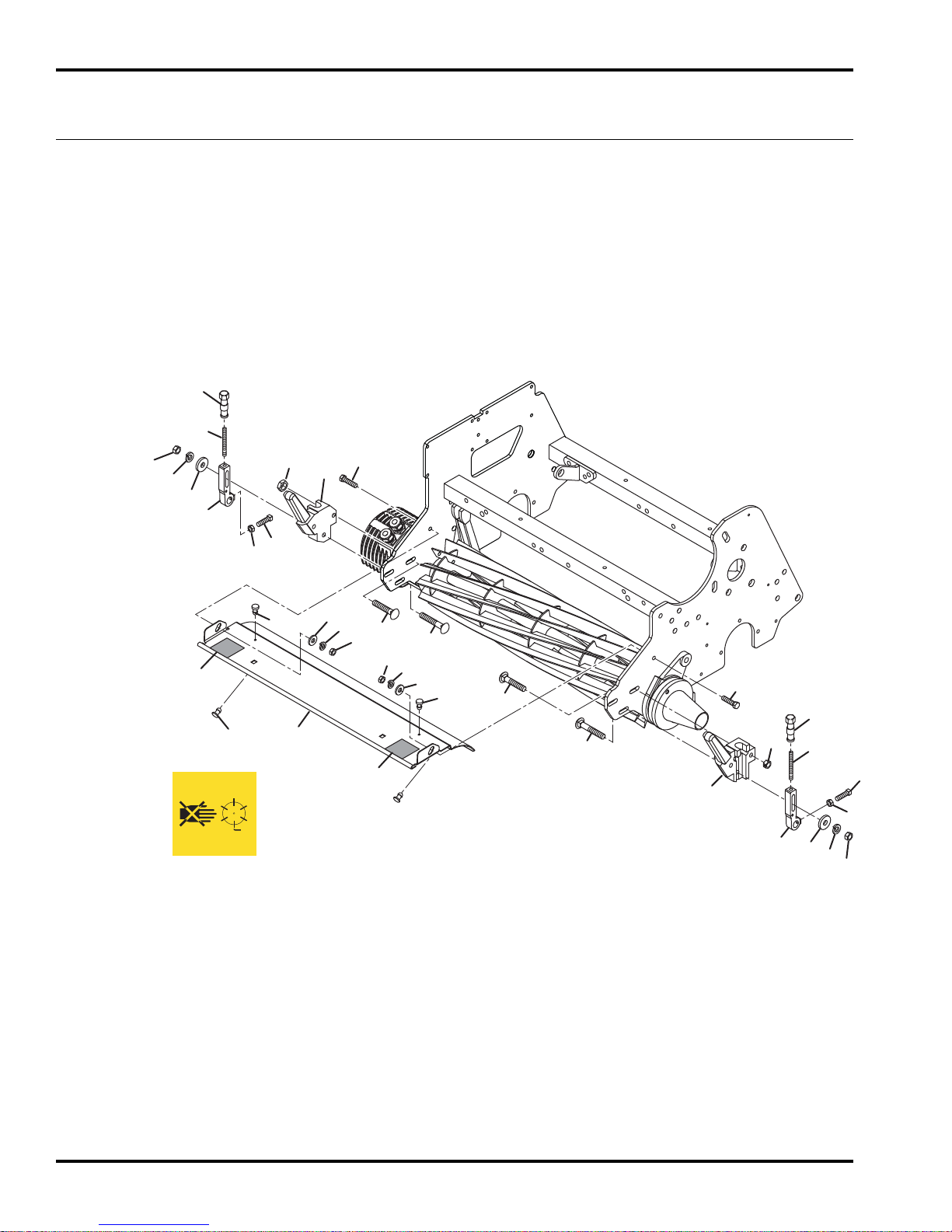
ECLIPSE
2
8.1 Grass Shield and Roller Brackets
Fixed Head Units Only
7
6
Serial No. 63334 - All
Serial No. 63335 - All
Serial No. 63338 - All
Serial No. 63339 - All
Serial No. 63342 - All
Serial No. 63343 - All
Serial No. 63344 - All
Serial No. 63347 - All
Serial No. 63348 - All
Serial No. 63351 - All
13
12
2
11
2
9
17
3
5
15
14
16
18
19
14
8
14
19
10
18
16
8
17
7
16
1
2
10
9
6
15
4
14
4127335
5
11
12
13
72
Page 73

ECLIPSE
Item Part No. Qty. Description Serial Numbers/Notes
1
1 4139660 1 Grass Shield, 22 Inch
1 4139662 1 Grass Shield, 26 Inch Used on 63342 and 63351
2 4127335 2 • Decal, Danger
3 241928 1 Bracket, Catcher Mounting, R.H.
4 241927 1 Bracket, Catcher Mounting, L.H.
5 2000072 2 Bracket, Roller Adjusting
6 343616 2 Stud, Front Roller Adjusting
7 3005692 2 Adjusting Knob
8 441677 4 Carriage Bolt 5/16-18 x 1-1/2”
9 444718 4 Locknut, 5/16-18 Center
10 441674 2 Carriage Bolt, 5/16-18 x 1-3/4”
11 364441 2 Spacer
12 446136 2 Lockwasher, 5/16 Heavy
13 443106 2 Nut, 5/16-18 Hex
14 443102 4 Nut, 1/4-20 Hex
15 352737 2 Set Screw, 1/4-20 x 7/8” Square Hd
16 3008974 4 Grommet
17 400112 2 Screw, 1/4-20 x 1” Hex Head
18 453023 2 Flat Washer, 1/4
19 446130 2 Lockwasher, 1/4 Heavy
4139661
1 Grass Shield, 18 Inch
Used on 63334, 63343, 63335, and
63344
Used on 63338, 63347, 63339, and
63348
2
> Change from previous revision
73
Page 74
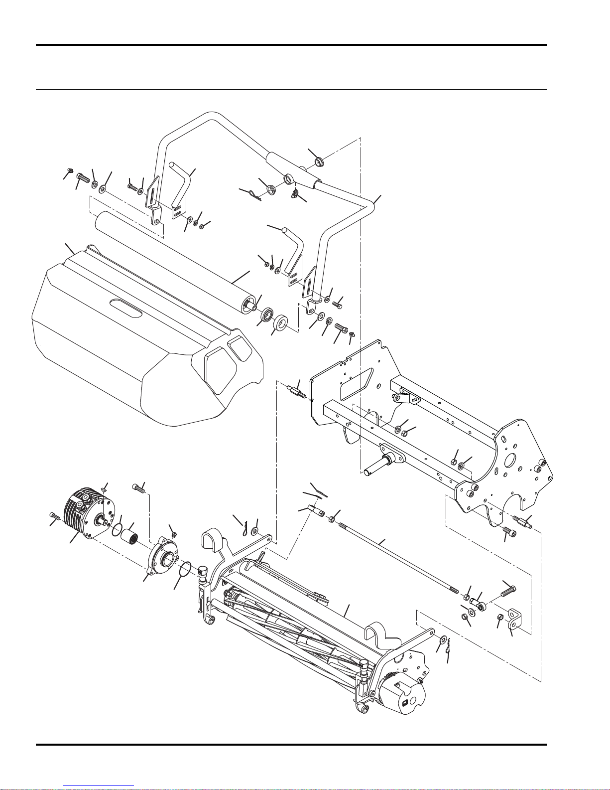
4
3
1
2
5
6
7
7
8
8
8
8
9
9
10
10
11
11
12
13
14
15
15
15
15
16
17
18
19
20
21
22
22
23
24
25
25
26
27
29
29
30
30
30
30
31
32
36
37
37
38
35
33
34
34
29
29
30
30
28
28
25
40
ECLIPSE
2
9.1 Floating Head Reel Connection
Floating Head Units Only
Serial No. 63336 - All
Serial No. 63337 - All
Serial No. 63340 - All
Serial No. 63341 - All
Serial No. 63345 - All
Serial No. 63346 - All
Serial No. 63349 - All
Serial No. 63350 - All
74
Page 75

ECLIPSE
Item Part No. Qty. Description Serial Numbers/Notes
1
4175221 1 Rear Roller - 18”
1 1004990 1 Rear Roller - 22”
2 4175220 1 • Shaft, 18”
2 3010422 1 • Shaft, 22”
3 3010286 2 • Seal
4 3010712 2 • Bearing
5 4168727 1 Roller Mount - 18”
5 4136994 1 Roller Mount - 22”
6 4203300 1 Grass Catcher, 18” Floating Head
6 4239563 1 Grass Catcher, 22” Floating Head
7 352726 2 Bushing
8 453023 8 Flat Washer, 1/4
9 446128 4 Lockwasher, 1/4 Med.
10 443102 4 Nut, 1/4-20 Hex
11 400108 4 Screw, 1/4-20 x 3/4” Hex Head
12 4140152 1 Mount, Left Side Catcher
13 4140151 1 Mount, Right Side Catcher
14 471221 1 Grease Fitting, 1/4-28 90°
15 460312 4 Hairpin
16 366317 1 Rod End, 3/8-24
17 4104720 1 O-Ring, Motor
18 4261470 1 Motor, Brushless Bi-Directional Reference M2, See 19.1
19 4167400 1 Plate, Motor Adapter
20 4169040 1 Rod, Panhard, 18”
20 4138778 1 Rod, Panhard, 22”
21 360893 1 Rod End
22 4140166 2 Pin, Threaded
23 434024 4 Screw, 5/16-18 x 3/4” Socket Head
24 434029 3 Screw, 1/4-20 x 3/4” Socket Head
25 443110 2 Nut, 3/8-16 Hex
26 443112 1 Nut, 3/8-24 Hex
27 445785 1 Nut, 3/8-24 Left Hand Hex
28 471214 2 Grease Fitting
29 446142 5 Lockwasher, 3/8 Heavy
30 453011 5 Flat Washer, 3/8
31 463029 1 Key, Woodruff
32 845279 1 Seal, O-Ring
33 REF 1 Reel Assembly See 10.1
34 4156930 2 Screw, 3/8-24 x 1” Special
35 2812384 1 Coupler
36 4261071 1 Bracket, Panhard Mount
37 444762 2 Locknut, 3/8-16 Hex Center
38 434030 1 Screw, 3/8-16 x 7/8” Hex Socket
39 417242 1 Fitting, Relief
40 400264 1 Screw, 3/8-16 x 1-1/4” Hex Head
41
Used on 63336, 63345, 63337, 63346
Used on 63340, 63349, 63341, 63350
Used on 63336, 63345, 63337, 63346
Used on 63340, 63349, 63341, 63350
Used on 63336, 63345, 63337, 63346
Used on 63340, 63349, 63341, 63350
Used on 63336, 63345, 63337, 63346
Used on 63340, 63349, 63341, 63350
Used on 63336, 63345, 63337, 63346
Used on 63340, 63349, 63341, 63350
2
> Change from previous revision
75
Page 76
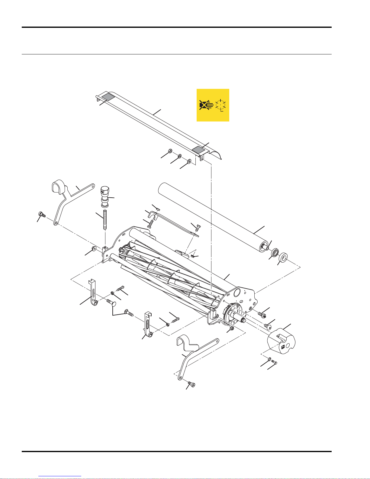
ECLIPSE
2
10.1 Outer Reel Assembly
Floating Head Units Only
Serial No. 63336 - All
Serial No. 63337 - All
Serial No. 63340 - All
Serial No. 63341 - All
Serial No. 63345 - All
Serial No. 63346 - All
Serial No. 63349 - All
Serial No. 63350 - All
28
10
4127335
28
28
12
8
13
25
18
14
6
22
23
26
21
1
2
20
20
27
4
3
76
16
19
12
15
17
12
15
24
5
11
7
20
8
9
6
Page 77

ECLIPSE
Item Part No. Qty. Description Serial Numbers/Notes
1
1 1004990 1 Rear Roller, 22”
2 4175220 1 • Shaft, 18” Roller
2 3010422 1 • Shaft, 22” Roller
3 3010286 2 • Seal
4 3010712 2 • Bearing
5 1002224 2 Zerk Bolt
6 365246 2 Shoulder Bolt
7 4171380 1 Casting, Counterweight
8 446130 4 Lockwasher, 1/4 Heavy
9 400118 2 Screw, 1/4-20 x 1-3/4” Hex Head
10 2811027 1 Shield, Reel, 18”
10 4174640 1 Shield, Reel, 22”
11 403782 2 Screw, 1/4-20 x 3/4” Truss Head
12 443102 4 Nut, 1/4-20 Hex
13 453023 2 Flat Washer, 1/4
14 343616 2 Stud
15 352737 2 Screw, 1/4-20 x 7/8” Sq Hd Set
16 3008438 1 Roller Bracket
17 3008439 1 Roller Bracket
18 3005692 2 Knob, Front Roller Adjusting
19 441674 2 Carriage Bolt, 5/16-18 x 1-3/4”
20 445795 4 Nut, 5/16-18 Spiralock Flange
21 400184 2 Screw, 5/16-18 x 3/4” Hex Head
22 4175240 1 Bracket, 118F Panhard Rod
22 4140163 1 Bracket, 122F Panhard Rod
23 4140164 1 Screw, 3/8-16 x 1-1/4 Special
24 4140284 1 Bar, Left Support
25 4140285 1 Bar, Right Support
26 443810 1 Nut, 3/8-16 Hex Jam
27 N/S 1 Inner Reel Assembly See 11.1
28 4127335 2 Decal, Danger
4175221 1 Rear Roller, 18”
Used on 63336, 63345, 63337, and
63346
Used on 63340, 63349, 63341, and
63350
Used on 63336, 63345, 63337, and
63346
Used on 63340, 63349, 63341, and
63350
Used on 63336, 63345, 63337, and
63346
Used on 63340, 63349, 63341, and
63350
Used on 63336, 63345, 63337, and
63346
Used on 63340, 63349, 63341, and
63350
2
> Change from previous revision
77
Page 78
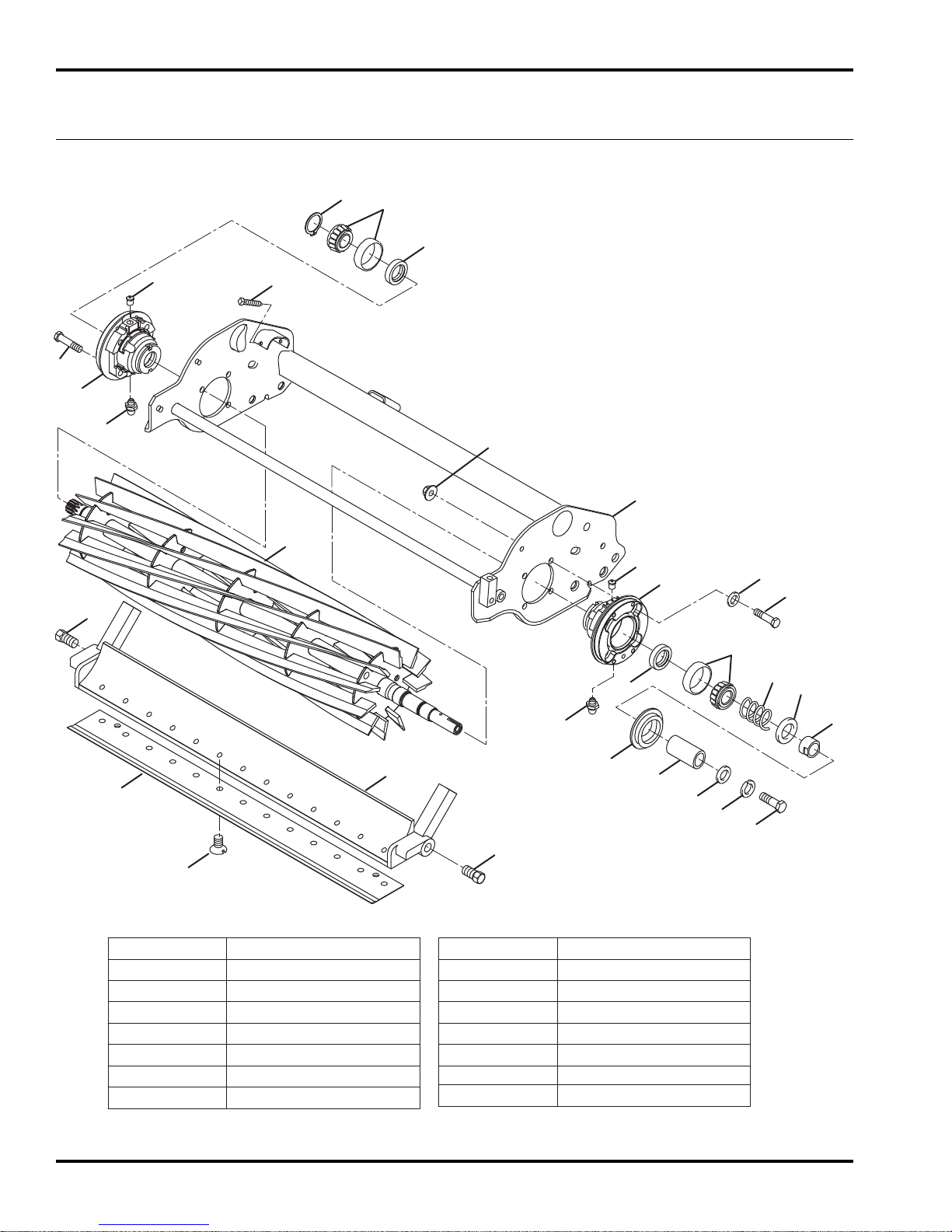
25
5
24
18
10
1
9
21
8
17
16
17
14
15
4
7
6
12
23
22
26
11
19
28
13
29
27
3
2
20
2
Optional MagKnife Bedknives
Part Number Description
4131369 22” High Profile
4131004 18” Super Tournament
4131373 18” Tournament
4131371 18” Low Profile
4131001 22” Low Profile
4131370 22” Tournament
4131003 22” Super Tournament
Standard Style Bedknives
(Secured with screws)
Part Number Description
5000098 18” Low Profile
● 5002888 18” Super Tournament
4234901 18” Championship
503478 22” Low Profile
503477 22” High Profile
4234900 22” Championship
● 5002887 22” Super Tournament
● Standard Bedknife
ECLIPSE
2
11.1 Inner Reel Assembly
Floating Head Units Only
Serial No. 63336 - All
Serial No. 63337 - All
Serial No. 63340 - All
Serial No. 63341 - All
Serial No. 63345 - All
Serial No. 63346 - All
Serial No. 63349 - All
Serial No. 63350 - All
78
Page 79

ECLIPSE
Item Part No. Qty. Description Serial Numbers/Notes
1
1 5002577 1 Frame, 22” Reel
2 400192 8 Screw, 5/16-18 x 1-1/2” Hex Head
3 446142 1 Lockwasher, 3/8 Heavy
4 4225504 1 15 Blade, 18” Left Hand Reel Used on 63337 and 63346
4 4225505 1 15 Blade, 22” Left Hand Reel Used on 63341 and 63350
4 4170220 1 11 Blade, 18” Left Hand Reel Used on 63336 and 63345
4 5001101 1 11 Blade, 22” Left Hand Reel Used on 63340 and 63349
4 5001099 1 9 Blade, 22” Left Hand Reel Optional Reel
4 5003053 1 7 Blade, 22” Left Hand Reel Optioanl Reel
5 1004756 1 Bearing Housing
6 500534 1 • Bearing, Cup and Cone
7 336962 1 • Seal, Grease
8 471214 1 • Grease Fitting
9 471242 1 • Vent Fitting
10 445795 8 Nut, 5/16-18 Spiralock Flange
11 304745 1 Washer
12 458013 1 Snap Ring
13 367164 1 Spacer
14 2811055 1 Backing, 18” Bedknife
14 2000068 1 Backing, 22” Bedknife
15 See Chart 1 Bedknife
16 4252470 AR Screw, 1/4-20 x 1/2” Bedknife Package of 100 Screws
17 315298 2 Wheel Bolt, 7/16 x 3/4”
18 412503 4 Screw, 3/8-16 x 1-1/4” Square Head
19 400294 1 Screw, 3/8-24 x 1” Hex Head
20 453009 4 Flat Washer, 5/16
21 1000480 1 Bearing Housing
22 500534 1 • Bearing, Cup and Cone
23 336962 1 • Seal, Grease
24 471214 1 • Grease Fitting
25 471242 1 • Vent Fitting
26 5002151 1 Spring, Compression
27 364900 1 Nut, Reel
28 453011 1 Flat Washer, 3/8
29 163892 1 Seal
4170204 1 Frame, 18” Reel
Used on 63336, 63345, 63337, and
63346
Used on 63340, 63349, 63341, and
63350
2
> Change from previous revision
79
Page 80
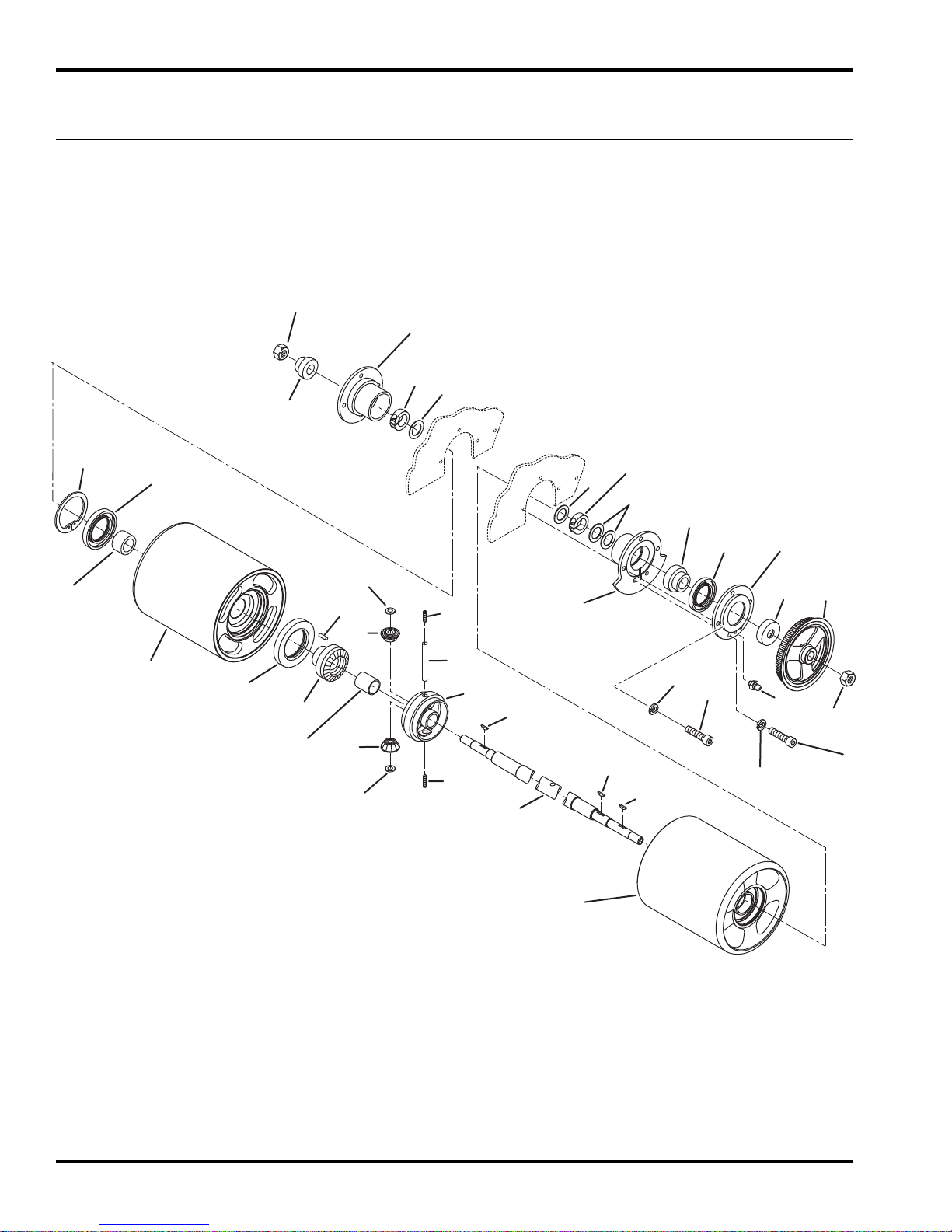
24
22
21
23
26
27
29
19
17
31
25
25
28
30
2
5
4
6
7
8
1
12
12
13
13
14
10
16
14
3
1
15
15
11
9
18
28
20
19
24
32
ECLIPSE
2
12.1 Differential and Rollers
Serial No. All
80
Page 81

ECLIPSE
Item Part No. Qty. Description Serial Numbers/Notes
1 1000024 2 18” Smooth Roller
1 132655 2 22” Smooth Roller
1 1000027 2 26” Dimpled Roller
2 366699 1 • Differential Gear Bushing
3 366698 1 • Drum Bushing
4 366701 1 • Grease Seal
5 366700 1 • Grease Seal
6 241836 1 • Differential Gear
7 319085 1 • Pin
8 458127 1 • Snap Ring
9 395419 1 18” Roller Shaft
9 395367 1 22” Roller Shaft
9 395418 1 26” Roller Shaft
10 241835 1 Differential
11 463017 1 Key, #9 Woodruff
12 308030 2 Thrust Washer
13 202947 2 Pinion Gear
14 415563 2 Set Screw, 7/16-20 x 3/8”
15 463007 2 Key, #7 Wooodruff
16 308028 1 Pinion Shaft
17 220318 1 Bearing Housing
18 220319 1 Bearing Housing
19 366693 2 Bearing
20 2810096 1 Nut, 1-14 Nylock Hex
21 241833 1 Seal Cover
22 366702 1 Grease Seal
23 471214 1 Grease Fitting
24 446136 5 Lockwasher,5/16 Heavy
25 366697 2 Spacer
26 366696 1 Spacer
27 3004484 1 Pulley, 56 Tooth
28 366695 2 Locking Collar
29 367029 1 Nut, 3/4-16 Hex Nylock Jam
30 434024 2 Screw, 5/16-18 x 3/4” Socket Head
31 361451 2 Washer
32 434003 3 Screw, 5/16-18 x 1” Socket Head
2
> Change from previous revision
81
Page 82
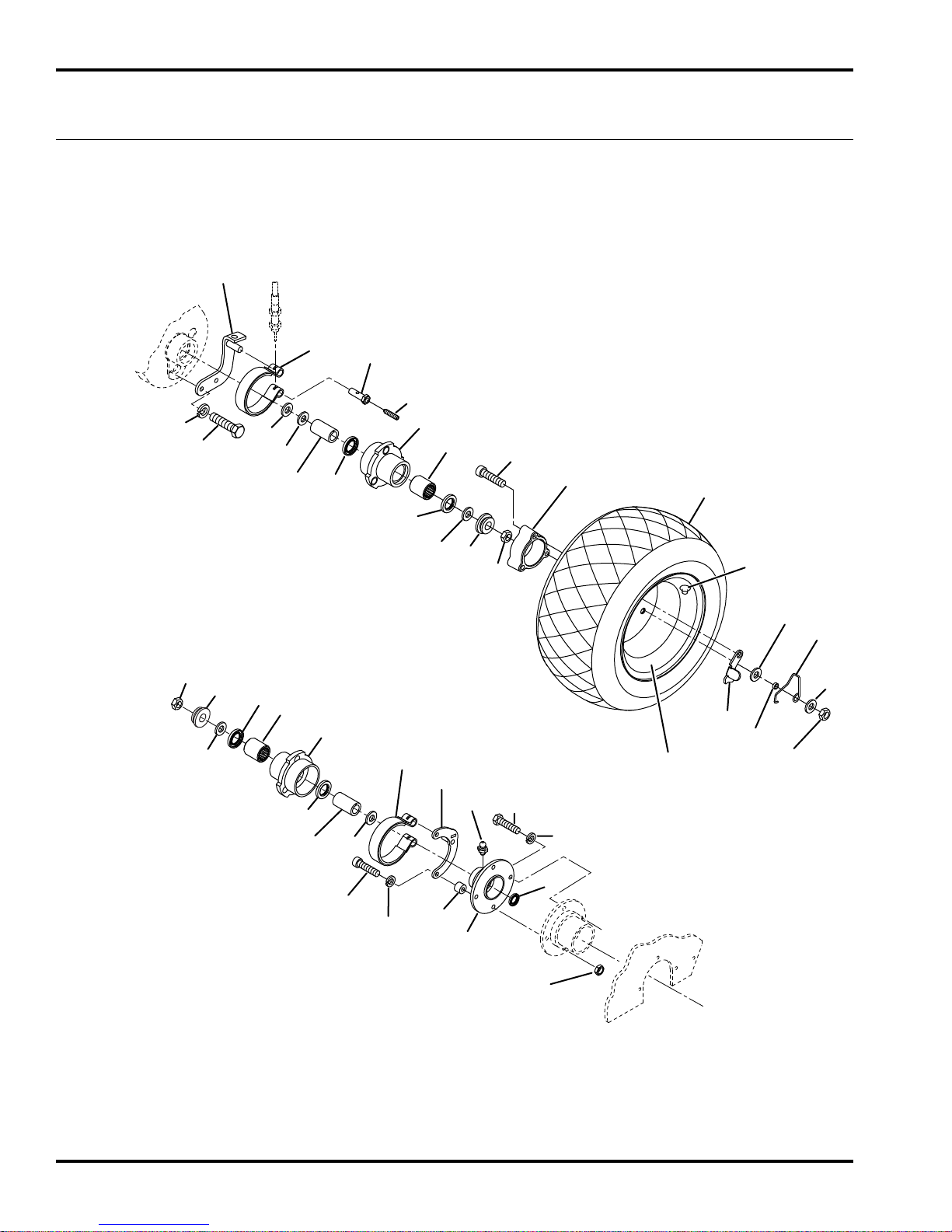
7
8
1
24
16
16
13
17
25
33
6
4
2
9
5
3
3
18
17
35
35
36
34
28
29
19
32
14
14
22
23
16
16
13
21
20
12
11
12
10
15
15
31
27
30
26
4
ECLIPSE
2
13.1 Parking Brake and Wheels
Serial No. All
82
Page 83

ECLIPSE
Item Part No. Qty. Description Serial Numbers/Notes
1
2 338766 1 • Bearing
3 366705 2 • Grease Seal
4 164056 2 Brake Band
5 132663 1 Brake Mounting Bracket
6 132658 1 Seal Housing
7 365753 1 • Grease Seal
8 4128725 1 • Grease Fitting
9 164063 1 Brake Mounting Bracket
10 1000477 1 L.H. Hub
11 338766 1 • Bearing
12 366705 2 • Grease Seal
13 366717 2 Clutch Sleeve
14 445801 2 Nut, 5/8-18 Hex Jam Lock
15 366718 2 Latching Collar
16 366697 4 Bushing
17 446136 4 Lockwasher, 5/16 Heavy
18 400188 2 Screw, 5/16-18 x 1” Hex Head
19 361451 1 Washer Left Side Only
20 415513 2 Set Screw, 1/4-20 x 1/2”
21 366742 2 Brake Band Pin
22 446130 2 Lockwasher, 1/4 Heavy
23 400108 2 Screw, 1/4-20 x 3/4” Hex Head
24 366737 2 Spacer
25 434032 2 Screw, 5/16-18 x 1-3/4” Socket Head
26 443106 1 Nut, 5/16-18 Hex
1000476 1 R.H. Hub
2
62293 1 Pneumatic Transport Tire Kit Optional Accessory
27 360111 2 • Valve
28 554847 2 • Tire
29 5002905 2 • Wheel, Gray
30 271920 2 • Wheel Spacer
31 434049 6 • Screw, 5/16-18 x 2” Socket Head
32 366719 2 • Latch
33 366716 6 • Spacer
34 366704 2 • Spring
35 452004 12 • Flat Washer, 5/16
36 444718 6 • Locknut, 5/16-18 Center
> Change from previous revision
83
Page 84
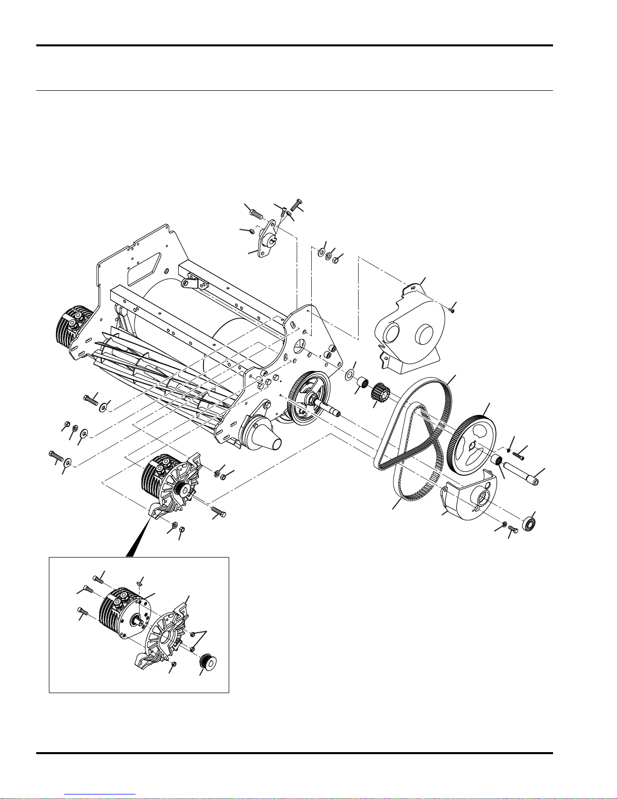
8
12
18
18
18
27
31
15
17
17
17
19
19
19
20
20
20
11
13
16
16
21
1
2
3
4
5
6
7
9
14
14
17
22
23
24
25
26
28
29
30
32
32
33
33
10
ECLIPSE
2
14.1 Belts and Drive Motors
Serial No. All
84
Fixed Head Frame Shown. Floating Head Similar
Page 85

ECLIPSE
Item Part No. Qty. Description Serial Numbers/Notes
2
1
2 2000148 1 Bracket, Bearing
3 2811070 1 Belt, Polychain, 80 Tooth
4 2811223 1 Pully, 18 Tooth
5 2811107 1 Pully, 112 Tooth
6 3001273 1 Shaft
7 4140154 1 Floating Head Pulley Cover
8 4199640 1 Cover, Belt
9 2811106 1 Belt, 130 Tooth
10 2811108 1 Pulley, 23 Tooth
11 4256571 1 Mount, Motor
12 4261470 1 Motor, Brushless Bi-Directional Reference M2, See 19.1
13 463029 1 Key, Woodruff
14 367554 2 Bearing, Needle
15 446130 2 Lockwasher, 1/4 Heavy
16 444708 3 Locknut, 1/4-20 Center
17 400190 4 Screw, 5/16-18 x 1-1/4” Hex Head
18 452006 3 Flat Washer, 5/16
19 446136 3 Lockwasher, 5/16 Heavy
20 443106 3 Nut, 5/16-18 Hex
21 434011 1 Screw, 14-20 x 5/8” Socket Head
22 400262 2 Screw, 3/8-16 x 1” Hex Head
23 453011 2 Flat Washer, 3/8
24 446142 2 Lockwasher, 3/8 Heavy
25 443110 2 Nut, 3/8-16 Hex
26 434034 2 Screw, 10-24 x 1” Socket Head
27 400106 2 Screw, 1/4-20 x 5/8” Hex Head
28 434031 1 Screw, 1/4-20 x 3/4” Socket Head
29 409807 3 Screw, 1/4-20 x 3/4” Thread Cutting
30 359864 AR Thrust Washer
31 366707 1 Ball Bearing
32 443806 2 Nut, 5/16-24 Hex Jam
33 434029 2 Screw, 1/4-20 x 3/4” Socket Head
446116 2 Lockwasher, #10
> Change from previous revision
85
Page 86
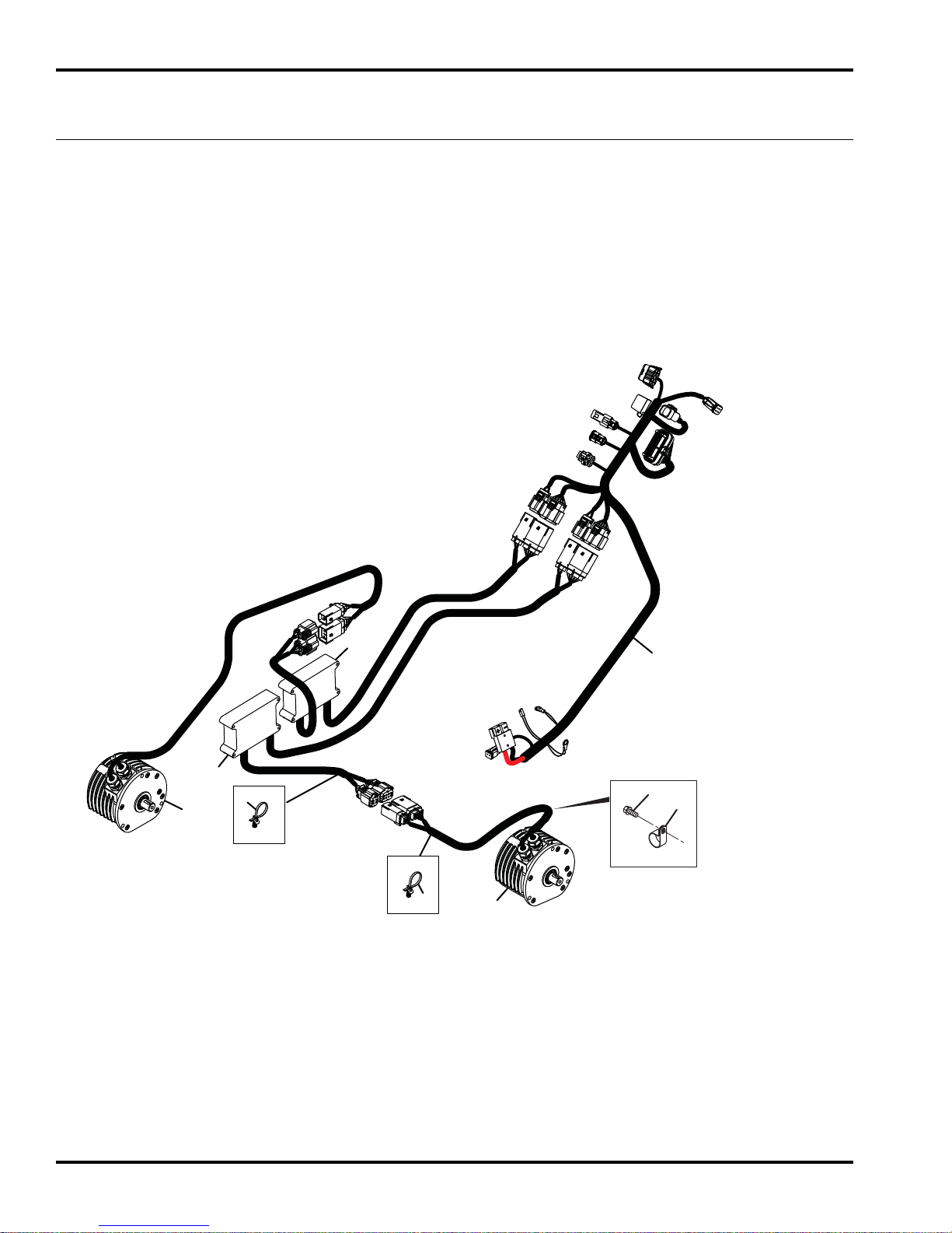
SW1Reel Switch
J14 CAN Diagnostic Connector
R1 Hand Throttle Potentiometer
R2 Rotary Switch
SW2 Ignition
Switch
F230 Amp Fuse
J1 and J2
Controller
Connection
J6 and J7
Reel Motor
Controller
Connection
J10 and J11
Reel Motor
Connection
J12 and 13
Tr action Motor
Connection
M1 Reel Motor
M2 Traction Motor
GC1
GC2
J22 and J24
Engine
Shutdown
J23 48V
Power
J15 Light Kit
J8 and J9
Tr action Motor
Controller
Connection
1
2
3
4
5
6
6
7
8
ECLIPSE
2
15.1 Harness Routing
Serial No. All
86
Page 87

ECLIPSE
Item Part No. Qty. Description Serial Numbers/Notes
4254330 1 Harness, Main
1
4262910 1 • 30 Amp Mini Fuse REFERENCE F1, See 19.1
2 4253190 1 Controller, Reel Motor REFERENCE U1, See 19.1, 4.1
3 4261770 1 Motor, Brushless Bi-Directional REFERENCE M1, See 19.1, 6.1, 9.1
4 4253190 1 Controller, Traction Motor REFERENCE U2, See 19.1, 4.1
5 4261770 1 Motor, Brushless Bi-Directional REFERENCE M2, See 19.1, 14.1
6 4245913 2 Clip, Cable Tie
7 354080 1 Clamp, 1” Tube
8 409807 1 Screw, 1/4-20 x 1/2” Thread Cutting
9 473142 12 Cable Tie, 3/16 x 14” Not Shown, harnes to handle.
2
> Change from previous revision
87
Page 88
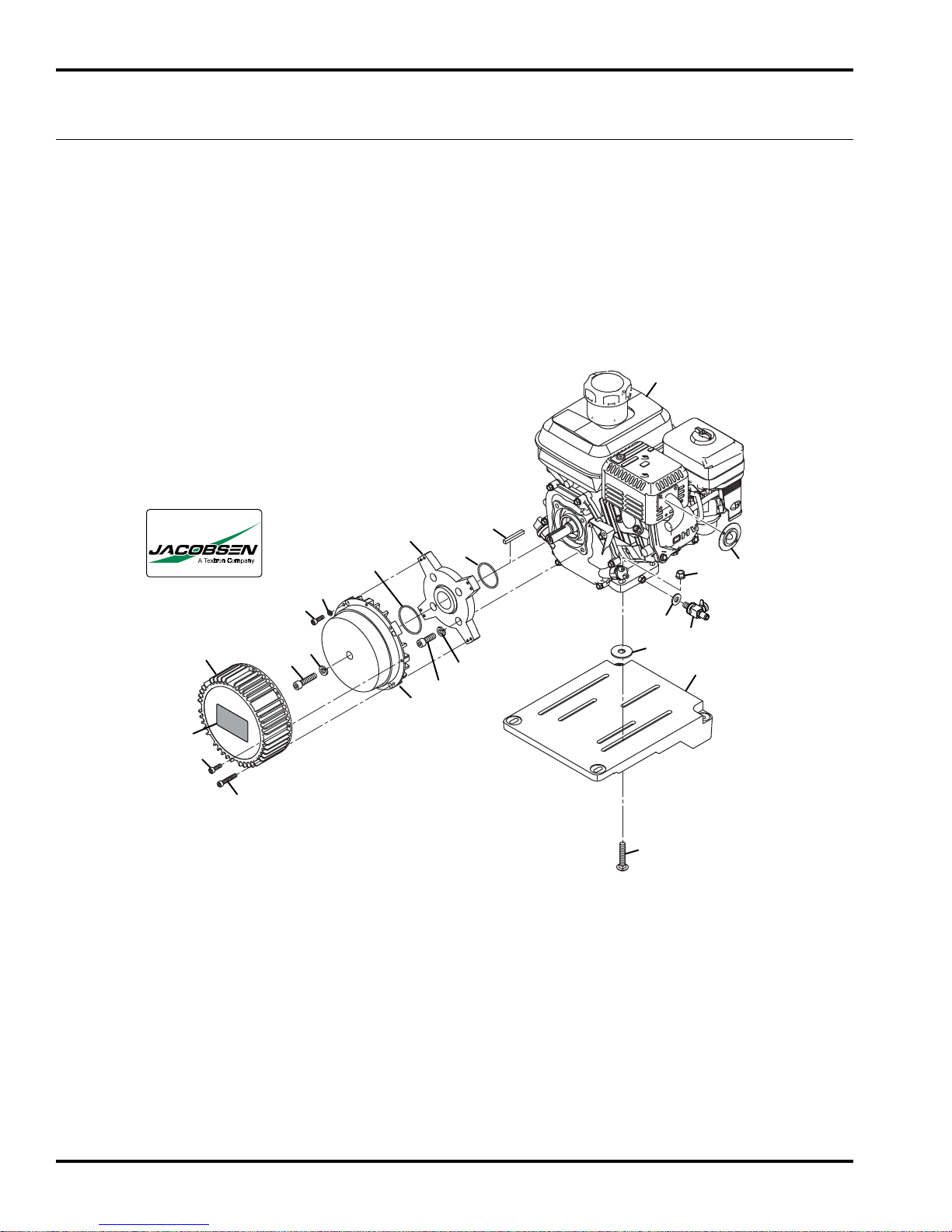
ECLIPSE
2
16.1 Genset Power Source
63305
Serial No. 63334 - All
Serial No. 63335 - All
Serial No. 63336 - All
Serial No. 63337 - All
Serial No. 63337 - All
Serial No. 63338 - All
Serial No. 63339 - All
Serial No. 63340 - All
1
Serial No. 63341 - All
20
14
17
21
20
11
2
3
9
®
10
12
18
17
5
4
19
16
16
8
6
15
13
7
88
Page 89

ECLIPSE
Item Part No. Qty. Description Serial Numbers/Notes
2
1
2 320774 1 • Key, 3/16 x1-1/2” Square
3 4170500 1 Trim, Muffler
4 4172080 1 Valve, Oil Drain
5 4187840 1 Gasket, Oil Drain Valve
6 4253595 1 Mount, Power Source
7 441977 4 Carriage Bolt, 5/16-18 x 1-1/2”
8 452010 4 Flat Washer, 3/8
9 548911 4 Nut, 5/16-18 Hex Flange
10 N/S 1 • Generator Adapter Base
11 N/S 1 • O-Ring, 2” O.D.
12 N/S 1 • O-Ring, 2-1/4” O.D.
13 N/S 1 • Generator
14 N/S 1 • Cover, Generator
15 434060 4 Screw, 5/16-24 x 7/8” Hex Socket
16 446136 5 Lockwasher, 5/16 Heavy
17 450697 8 Screw, M5-.8 x 16 mm Hex Socket
18 450409 4 Lockwasher, M5
19 800646 1 Screw, 5/16-24 x 1-1/4” Hex Socket
20 4182386 1 Decal, Jacobsen
21 450700 4 Screw, M5-.5 x 30 mm Hex Socket
4258930 1 Engine, Honda GX-120
4258510 1 Generator, Eclipse II REFERENCE U3, See 19.1
> Change from previous revision
89
Page 90
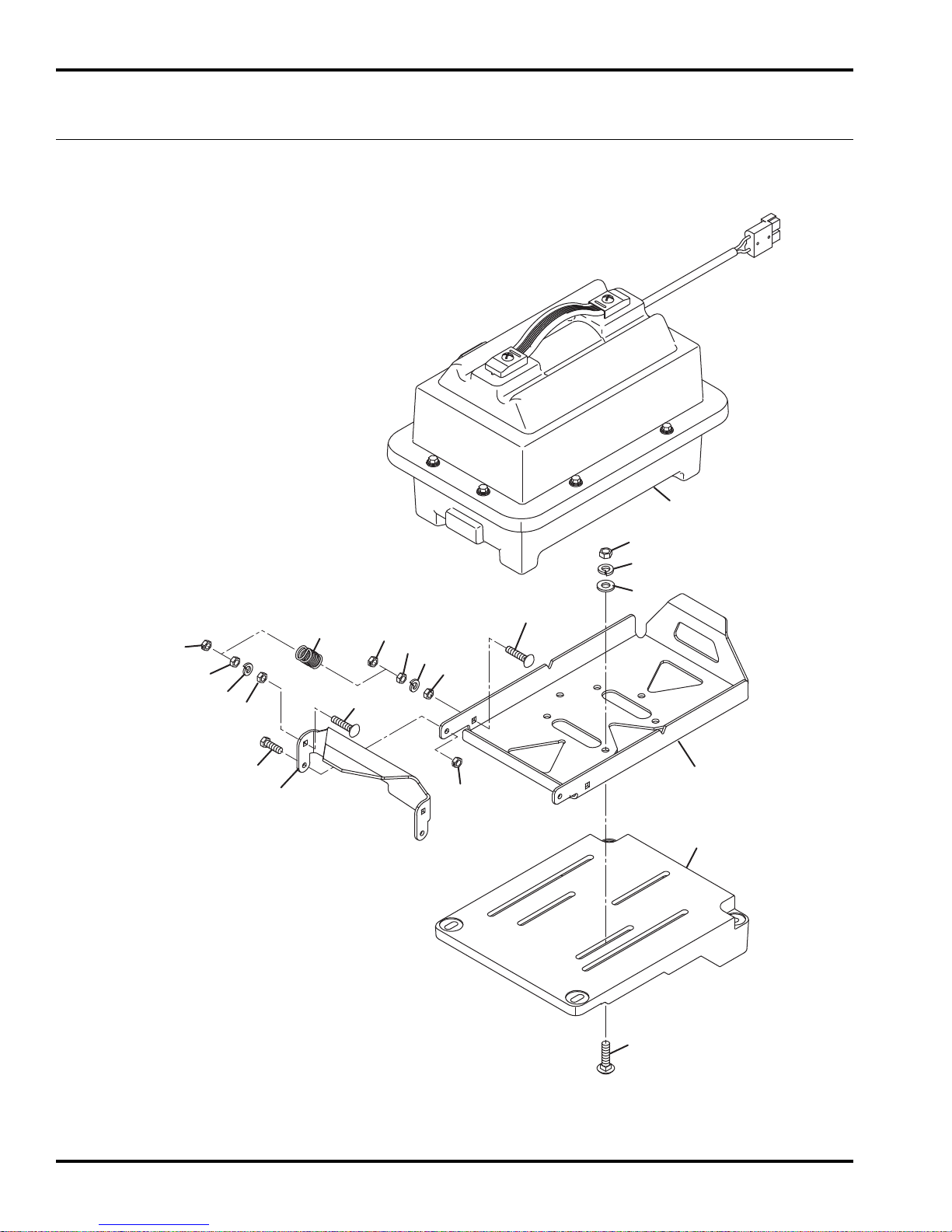
1
2
2
2
3
3
3
3
4
4
5
5
6
7
8
9
10
11
12
13
14
ECLIPSE
2
17.1 Battery Power Source
63306
Serial No. 63343 - All
Serial No. 63344 - All
Serial No. 63345 - All
Serial No. 63346 - All
Serial No. 63347 - All
Serial No. 63348 - All
Serial No. 63349 - All
Serial No. 63350 - All
Serial No. 63341 - All
90
Page 91

ECLIPSE
Item Part No. Qty. Description Serial Numbers/Notes
2
1
2 444708 6 Locknut, 1/4-20 Center
3 443102 8 Nut, 1/4-20 Hex
4 446130 4 Lockwasher, 1/4 Heavy
5 441604 4 Carriage Bolt, 1/4-20 x 1”
6 400108 2 Screw, 1/4-20 x 3/4 Hex Head
7 443106 3 Nut, 5/16-18 Hex
8 446136 3 Lockwasher, 5/16 Heavy
9 452006 3 Flat Washer, 5/16
10 440082 3 Carriage Bolt, 5/16-18 x 1”
11 4104080 1 Battery Tray
12 2811206 1 Clip
13 4253595 1 Power Module Mount
14 68668 1 Battery Pack See 18.1
2809837 2 Spring, Extension
> Change from previous revision
91
Page 92
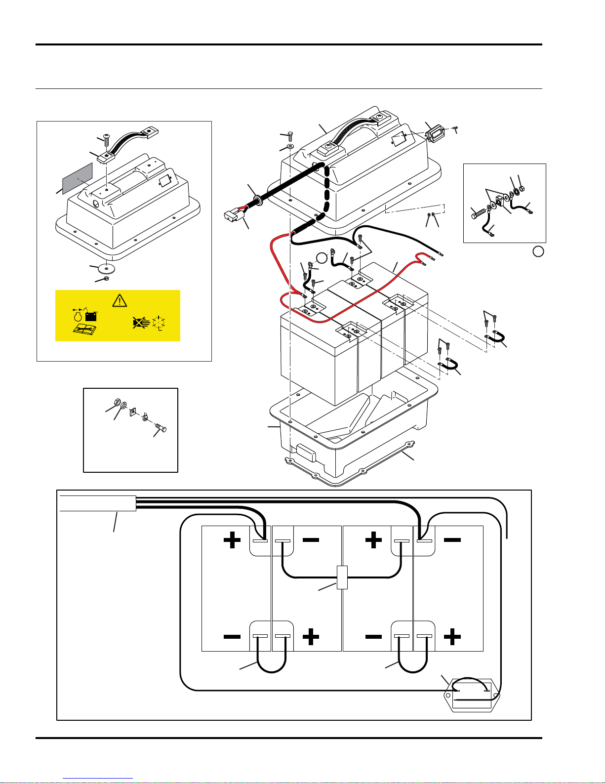
ECLIPSE
2
18.1 Battery Case
Serial No. All
20
20
STOP
18
16
19
17
4170001
15
23
14
26
21
5
8
1
27
7
6
10
A
10
6
10
24
25
To Battery
Gauge
2
4
6
3
6
A
10
10
9
9
12
11
10
Battery Post Style
Terminal Hardware
7
22
See Above
9
9
Battery and Battery Monitor Connections
13
14
P
KEY
N
92
Page 93

ECLIPSE
Item Part No. Qty. Description Serial Numbers/Notes
68668 1 Battery Case Does Not Include Batteries
1
2 452004 2 • Flat, Washer 1/4
3 4105800 1 • Fuse, 50A Reference F1, See 19.1
4 447214 1 • Lockwasher, 5/16 Internal
5 443106 1 • Nut, 5/16 Hex
6 2811664 2 • Cable
7 2811662 1 • Main Cable
8 366984 1 • Grommet
9 2811663 2 • Cable, Jumper
10 403741 8 • Screw, #8-32 x 5/8” Hex Head
11 444306 8 • Nut, 8-32 Hex
12 446112 8 • Lockwasher, #8 Heavy
13 4101600 2 • Strap, Battery Case
14 4245270 1 • Gauge, Battery Reference U4, See 19.1
15 2811221 1 • Lid, Battery Case Includes Decals
16 455058 2 • • Flat Washer, 1/4
17 444708 2 • • Locknut, 1/4-20, Center Lock
18 2811220 1 • • Handle, Battery Case
19 404022 2 • • Screw, 1/4-20 x 1” Truss Head
20 4170001 1 • • Decal, Danger
21 453023 8 • Flat Washer, 1/4
22 2809762 1 • Battery Case, Lower Half
23 408851 8 • Screw, 1/4-20 x 3/4” Hex Self Tap
24 444304 2 Nut, #6-32 Hex
25 N/S 4 Battery, 12V Reference B1, B2, B3, B4, See 19.1
26 402006 2 Screw, #6-32 x 1/2” Slotted Round
27 450419 2 Flat Washer, #6
4105660 1 • Screw, 5/16-18 x 1-1/4” Nylon
2
> Change from previous revision
93
Page 94
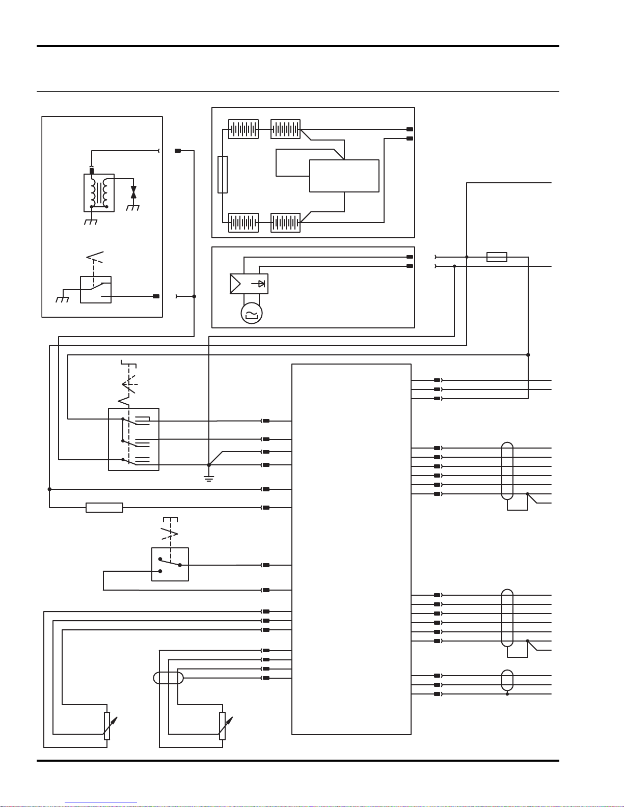
Run
Start
Off
E
F
D
A
J2-25
J24
J22
J23- –
J23- +
J23- –
J23- +
P
N
Key
J2-24
Red
Wht/Red
J2-15
J2-16
J2-29
B
Wht/Red
Red
SW2
Key
Switch
GC1
Yel
On
Off
SW1
Mow
Switch
R3
5Ω
Resistor
R2
Bail
Potentiometer
R1
Throttle
Potentiometer
SW3
Engine
On/Off
Switch
T1
Ignition
Coil
E1
Spark
Plug
F1
50A
B1B2
B3B4
F2
30A
U4
Battery Gauge
U3
1kW
Generator
U5
MCU
Controller
3
2
Red/Wht
Red/Wht
+15V Output
+48V Input
+48V Reel Motor
+48V Traction Motor
Blk
Brn
Blk
Blk
Blk
Blk
Blk
Key-Ignition
RedRed
BlkRed
Key-Start
Mow Enable Input
Throttle Pot +5V
Throttle Pot Wiper
Throttle Pot –
J2-13
G
U
Red/Wht
Red/Wht
Red/Blu
Red
J1-3
RedJ1-1
Red/Blu
J1-2
J2-14Yel
On
Off
Blk Blk
Red Red/Yel Red Red/Yel
Reel Motor Speed
Reel Motor Dir
Reel Motor Enable
Reel Motor Gnd
Grn
J2-21
Blu
J2-9
Wht
J2-8
Blk
J2-10
Reel Motor Temp
Red
J2-12
Reel Motor Tach
Brn
J2-17
CAN High
CAN Low
CAN Shield
RedJ2-1
BlkJ2-2
ShldJ2-3
J2-33
Resistor Gnd
Resistor -Ref
J2-35
Resistor +Ref
J2-34
J2-31
J2-32
J2-30
Red/Blu
Grn/Blu
Blk/Blu
Shld
Red/Blu
Grn/Blu
Blk/Blu
Red/Grn
Grn
Blk/Grn
Red/Grn
Grn
Blk/Grn
Bail Pot +5V
Bail Pot Wiper
Bail Pot –
J2-27
Throttle Pot Shieldg
Blk
Red
Grn
J2-5
Blu
J2-20
Wht
J2-19
Blk
J2-4
Red
J2-11
Traction Motor Speed
Traction Motor Dir
Traction Motor Enable
Traction Motor Gnd
Traction Motor Temp
Traction Motor Tach
Brn
Grn
Blu
Wht
Red
Brn
Grn
Blu
Wht
Red
Brn
Red
Blk
Red
Red
Blk
Yel
Blk
J2-6
Engine Control
(Hybrid Genset)
Generator
(Hybrid Genset)
Battery Pack
(Battery)
Yel
Red
Blk
Shld
MCU Gnd
Blk
J2-26
ECLIPSE
2
19.1 Electrical Schematic
Serial No. All
94
Page 95
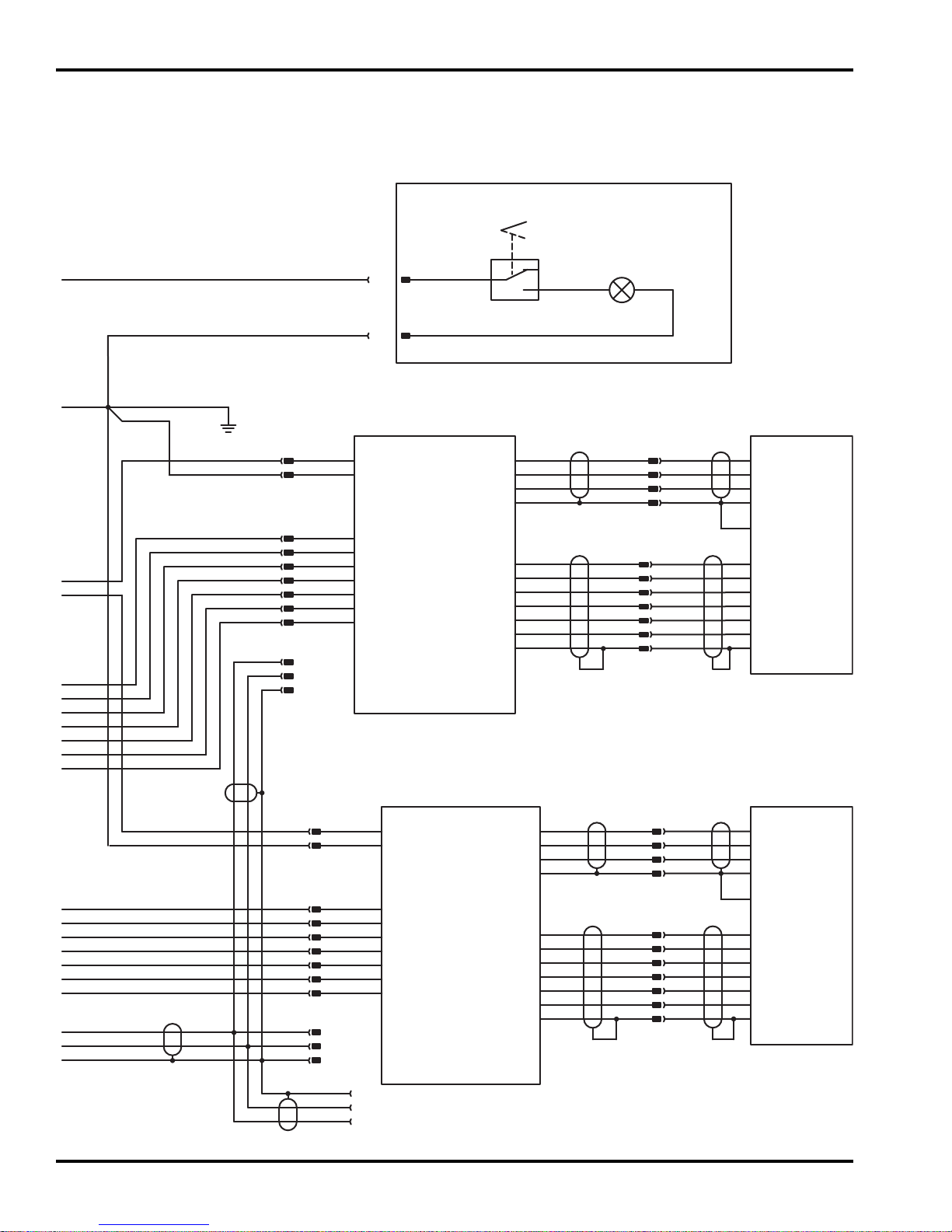
U2
Traction
Motor
Controller
U1
Reel
Motor
Controller
M1
Reel
Motor
Red
Blk
Shld
SW4
Light
Switch
L1
Work
Light
Optional
Work Light
Kit
On
Off
Blk
Grn
Blu
Wht
Red
Brn
Grn
Blu
Wht
Red
Brn
Grn
Blu
Wht
Red
Brn
Grn
Blu
Wht
Red
Brn
Blk
Red
Red
Red
Blk
Yel
Blk
J6-8
J6-9
J6-10
J14-C
J14-B
J14-A
+48V Input
Gnd
Phase A
Phase C
J7-1 J10-1
J10-2
J10-3
J11-3
J11-4
J11-5
J11-6
J11-2
Motor Speed
Motor Dir
Motor Enable
Motor Gnd
Motor Temp
Motor Tach
J11-1
J6-1
J6-2
J6-3
J7-2
J6-4
J6-5
J6-6
J11-7
Org
Yel
Grn
Gy
Brn
Blu
Gn/Ye
M2
Traction
Motor
Phase A
Phase B
Phase C
J8-8
J8-9
J8-10
+48V Input
Gnd
Phase B
J9-1
J15-1
J15-2
J12-1
J12-2
J12-3
Shield
Phase A
Phase C
Phase B
Shield
J10-4
Blk
Wht
Red
Gn/Ye
Org
Yel
Grn
Gy
Brn
Blu
Gn/Ye
Blk
Wht
Red
Gn/Ye
Shield
Motor
Case
J12-4
HALL B
HALL C
Signal Gnd
Temp
J13-3
J13-4
J13-5
J13-6
HALL A
J13-2
+5V Output
Motor Speed
Motor Dir
Motor Enable
Motor Gnd
Motor Temp
Motor Tach
J13-1
CAN
Diagnostic
Connector
J8-1
J8-2
J8-3
J9-2
J8-4
J8-5
J8-6
Shield
HALL B
HALL C
Signal Gnd
Temp
HALL A
+5V Output
Shield
HALL B
HALL C
Signal Gnd
Temp
HALL A
+5V Sensor Support
Shield
HALL B
HALL C
Signal Gnd
Temp
HALL A
+5V Sensor Supply
Shield
J13-7
Blk
Blk
Motor Speed -
J8-7
Yel
Grn
Blu
Vio
Red
Brn
Blk
Red
Blk
Wht
Gry
Yel
Red
Red
Red
Blk
Blu BlkBlu
Red
Blk
Red
Blk
Wht
Blk
Shld
Shld
Blk
Red
Red
Blk
Shld
Blk
Yel
J6-7
Motor Speed -
Yel
Grn
Blu
Vio
Red
Brn
Blk
Yel
Org
Yel
Grn
Gy
Brn
Blu
Gn/Ye
Org
Yel
Grn
Gy
Brn
Blu
Gn/Ye
Wht
Red
Blk
Wht
Red
Gn/Ye Gn/Ye
Blk
Phase A
Phase B
Phase C
Shield
Motor
Case
ECLIPSE
2
95
Page 96

ECLIPSE
2
Item
M1 See 6.1 or 9.1 4261470 Reel Motor
M2 See 14.1 4261470 Traction Motor
SW1 See 1.1 4165020 Key Switch
SW2 See 1.1 4130132 Reel Switch
SW3 Not Shown N/S Engine Shut Down Switch Included with Engine
SW4 Not Shown 4208861 Light Switch
Reference
Illustration
B1 See 18.1 N/S 12 Volt SLA Battery
B2 See 18.1 N/S 12 Volt SLA Battery
B3 See 18.1 N/S 12 Volt SLA Battery
B4 See 18.1 N/S 12 Volt SLA Battery
E1 Not Shown N/S Spark Plug Included with Engine
F1 See 18.1 4105800 50 Amp Fuse (Battery) Battery Power Module Only
F2 Not Shown 4262910 30 Amp Fuse (Main) Included with Harness
L1 Not Shown 4187221 48V Work Light Part of optional light kit 63320
R1 See 2.1 4260432 Hand Throttle Potentiometer
R2 See 2.1 4145428 Bail Lever Potentiometer
R3 See 4.1 4260610 Resistor, 5Ω Ceramic
T1 Not Shown N/S Ignition Coil Included with Engine
U1 See 4.1 4253190 Reel Motor Controller
U2 See 4.1 4253190 Traction Motor Controller
U3 See 16.1 4258510 Generator, 1kW Gen-Set Power Module Only
U4 See 18.1 4245270 Battery Gauge Battery Power Module Only
U5 See 1.1 4253551 MCU Controller
Part
Number
Description Serial Numbers/Notes
Obtain batteries localy or
through your Jacobsen Dealer
Battery Power Module Only
96
Page 97
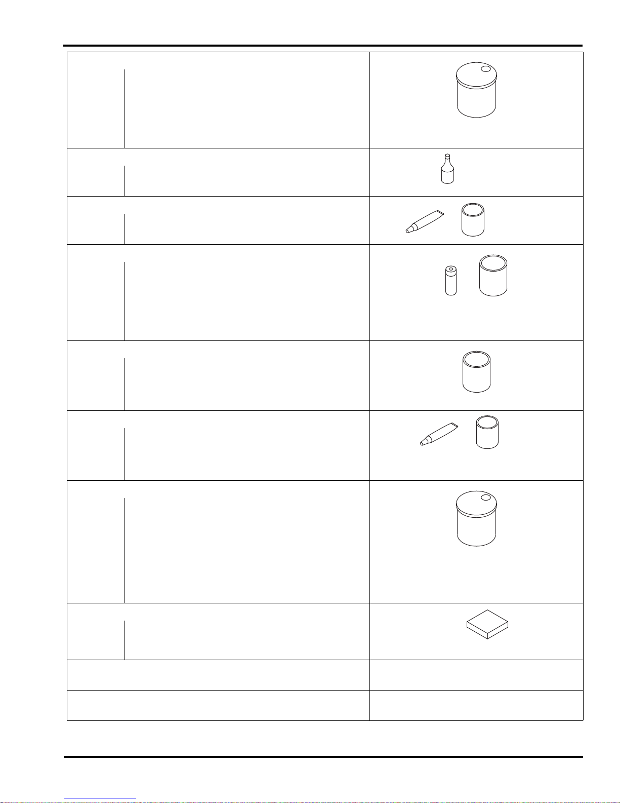
Fluids and Compounds
Hydraulic Fluid*
5001405 Two 2-1/2 Gallon Container of ISO VG68 Oil
5001404 One 5 Gallon Pail of ISO VG68 Oil
2500548 Two 2-1/2 Gallon Container of 10W30 Oil
2500546 One 5 Gallon Pail of 10W30 Oil
503409 Two 2-1/2 Gallon Container of ATF Fluid
503407 One 5 Gallon Pail of ATF Fluid
2-Cycle Oil
554599 Twenty Four 8 Ounce Plastic Container
Grease
5000067 One 5 Gallon Pail OO-Grease
5000068 Twenty Four 8 Ounce Tube OO-Grease
Paint
4184140 12 Ounce Orange Aerosol Can
2500789 Twelve 1 Quart Can Orange
546409 Two 1 Gallon Can Orange
5002631 Hunter Green Aerolol Can
838140 16 Ounce Ransomes Green Aerosol Can
4112764 1 Quart Can Ransomes Green
Lapping Compound
5002488 One 10 Pound Pail of 80 Grit
5002490 One 25 Pound Pail of 80 Grit
5002489 One 10 Pound Pail of 120 Grit
5002491 One 25 Pound Pail of 120 Grit
Specialty Compound
365422 5.3 Ounce Tube of Electrical Insulating Gel
5001581 14 Ounce Can of Lubriplate Multi Lube A
523248 Chain Lubricant
4136736 Zinc Spray Corrosion Protection
Biodegradable Hydraulic Fluid*
5003102 One 55 Gallon Drum Jacobsen GreensCare 68
5003103 One 5 Gallon Pail Jacobsen GreensCare 68
5003105 One 55 Gallon Drum Jacobsen GreensCare 46
5003104 One 5 Gallon Pail Jacobsen GreensCare 46
4115976 One 55 Gallon Drum Jacobsen GreensCare 32
4115977 One 5 Gallon Pail Jacobsen Greens Care 32
4114701 GreensCare Bio-Flush
5003106 Twenty Four 14 Ounce Tube Greens Care Grease
O-Ring Kit
5002452 SAE O-Ring Boss (3/32 ~ 2” Tube O.D.)
5002453 Common O-Ring Kit
5002454 O-Ring Face Seal ORFS (-4 ~ -24 ORS Tube Size)
Right Start Kit for New Machines
See your local Jacobsen Dealer
On-Time Maintenance Kit
See your local Jacobsen Dealer
* Refer to the Operator’s manual or the Parts & Maintenance Manual for the correct hydraulic oil requirements for your machine.
Jacobsen offers a High Usage Parts Catalog illustrating commonly used Parts through easy to read line Drawings. See your local
Jacobsen Dealer for a copy.
Page 98

INDEX
1000024.......................81
1000027.......................81
1000476.......................83
1000477.......................83
1000480.......................79
1002224.......................77
1004756.......................79
1004990.................75
132655.........................81
132658.........................83
132663.........................83
163892.........................79
164056.........................83
164063.........................83
2000067.......................59
2000068.......................79
2000072.......................73
2000075.......................71
2000076.......................71
2000148.......................85
202947.........................81
220318.........................81
220319.........................81
241833.........................81
241835.........................81
241836.........................81
241927.........................73
241928.........................73
271920.........................83
2809762.......................93
2809837.......................91
2809900.......................63
2809901.......................63
2810096.......................81
2811027.......................77
2811055.......................79
2811070.......................85
2811106.......................85
2811107.......................85
2811108.......................85
2811206.......................91
2811220.......................93
2811221.......................93
2811223.......................85
2811559.......................63
2812384.................69
3001273.......................85
3001610.......................69
3004484.......................81
3005692.................73
3008438.......................77
3008439.......................77
3008974.......................73
3010286.................75
3010422.................75
3010712.................75
, 77
, 75
, 77
, 77
, 77
, 77
304745.................. 71
306998.........................65
308028.........................81
308030.........................81
315298.........................79
319085.........................81
320774.........................89
332844.........................67
336962.........................79
338766.........................83
343616.................. 73
344132.........................65
352726.........................75
352737.................. 73
354080.........................87
359864.........................85
360111.........................83
360893.........................75
361139.........................65
361451.................. 81
364154.........................61
364164.........................65
364441.........................73
364900.................. 71
365246.........................77
365501.........................71
365753.........................83
366317.........................75
366648.........................69
366650.........................71
366653.........................69
366693.........................81
366695.........................81
366696.........................81
366697.................. 81
366698.........................81
366699.........................81
366700.........................81
366701.........................81
366702.........................81
366704.........................83
366705.........................83
366707.........................85
366708.........................59
366709.........................69
366715.........................65
366716.........................83
366717.........................83
366718.........................83
366719.........................83
366726.........................69
366727.........................69
366737.........................83
366742.........................83
366984.........................93
367029.................. 69
, 79
, 77
, 77
, 83
, 79
, 83
, 81
367164 .................. 69
367512 ........................ 69
367554 ........................ 85
395367 ........................ 81
395418 ........................ 81
395419 ........................ 81
400058 ........................ 65
400106 ........................ 85
400108 ......69
400112 ........................ 73
400118 ........................ 77
400184 ........................ 77
400186 ........................ 65
400188 ........................ 83
400190 .................. 65
400192 .................. 67
400196 ........................ 65
400198 ........................ 65
400200 ........................ 67
400204 ........................ 65
400258 ........................ 69
400262 ........................ 85
400264 .................. 69
400268 .................. 59
400274 ........................ 63
400286 ........................ 63
400294 .................. 69
400404 ........................ 65
400410 ........................ 65
402006 ........................ 93
402022 ........................ 61
402056 ........................ 59
403741 ........................ 93
403782 ........................ 77
404016 ........................ 65
404022 ........................ 93
408851 ........................ 93
409807 ......59
4101600 ...................... 93
4104080 ...................... 91
4104720 ................ 69
4105281 ...................... 71
4105660 ...................... 93
4105800 ................ 93
4117466 ...................... 67
412503 ........................ 79
4127335 ................ 73
4127340 ...................... 59
4127931 ...................... 67
4128725 ................ 71
4128933 ...................... 61
4130132 ................ 59
4131001 ................ 71
4131003 ................ 71
4131004 ...................... 79
4131005 ...................... 71
, 75, 83, 91
, 65, 85, 87
, 79
, 85
, 79
, 75
, 65
, 79
, 75
, 96
, 77
, 83
, 96
, 79
, 79
4131369 ................71
4131370 ................71
4131371 ...................... 79
4131373 ...................... 79
4131618 ...................... 59
4136325 ...................... 61
4136328 ...................... 61
4136366 ...................... 61
4136994 ...................... 75
4137303 ...................... 61
4137577 ...................... 75
4138778 ...................... 75
4139660 ...................... 73
4139661 ...................... 73
4139662 ...................... 73
4140151 ...................... 75
4140152 ...................... 75
4140154 ...................... 85
4140163 ...................... 77
4140164 ...................... 77
4140166 ...................... 75
4140284 ...................... 77
4140285 ...................... 77
4145428 ................61
4147696 ...................... 61
415513 ........................ 83
415563 ........................ 81
4156781 ...................... 61
4156930 ...................... 75
4165020 ................59
4167541 ...................... 69
4168727 ...................... 75
4169040 ...................... 75
4169640 ...................... 67
4170001 ...................... 93
4170202 ...................... 71
4170203 ...................... 71
4170204 ...................... 79
4170220 ...................... 79
4170500 ...................... 89
4171380 ...................... 77
4172080 ...................... 89
417242 ........................ 75
4172945 ...................... 71
4174640 ...................... 77
4175220 ................75
4175221 ................75
4175240 ...................... 77
4179720 ...................... 71
4179780 ...................... 69
4182386 ...................... 89
4187221 ...................... 96
4187840 ...................... 89
4193060 ...................... 65
4196280 ...................... 61
4199640 ...................... 85
, 79
, 79
, 96
, 96
, 77
, 77
98
Page 99

INDEX
4203300...................... 75
4208861...................... 96
4223946...................... 71
422504........................ 61
4225502...................... 71
4225504...................... 79
4225505...................... 79
4234900...................... 79
4234901................ 71
4239563...................... 75
4245270................ 93
4245913...................... 87
4247754...................... 67
4247755...................... 65
4252470................ 71
4253154...................... 67
4253155...................... 67
4253156...................... 67
4253157...................... 67
4253190.......... 65
4253310...................... 59
4253330...................... 59
4253551................ 59
4253595.......... 65
4254050...................... 59
4254330...................... 87
4255550...................... 65
4255551...................... 65
4255870...................... 67
4256571...................... 85
4256578...................... 61
4256692...................... 61
4257453...................... 67
4257455...................... 65
4257467...................... 65
4257470...................... 67
4257770...................... 65
4257813...................... 63
4257814...................... 63
4258190...................... 67
4258510................ 89
4258590...................... 65
4258790...................... 59
4258791...................... 59
4258830...................... 59
4258930...................... 89
4259130...................... 65
4260432................ 61
4260610...................... 96
4260810...................... 59
4261071...................... 75
4261470....69
4264210...................... 65
4265170...................... 59
4265171...................... 59
4265172...................... 59
, 75, 85, 96
, 79
, 96
, 79
, 87, 96
, 96
, 89, 91
, 96
, 96
4265710 ...................... 65
4273518 ...................... 67
4324900 ...................... 71
434003 ........................ 81
434011 ........................ 85
434024 .................. 75
434028 ........................ 69
434029 ............ 61
434030 .................. 67
434031 .................. 61
434032 ........................ 83
434034 ........................ 85
434036 ........................ 69
434049 .................. 69
434054 ........................ 61
434060 ........................ 89
440082 ........................ 91
441604 ........................ 91
441672 ........................ 67
441674 .................. 73
441677 ........................ 73
441688 ........................ 67
441977 ........................ 89
443102 61
443106 73
443110 ......59
443112 ........................ 75
443118 ........................ 65
443806 ........................ 85
443810 .................. 65
443828 ........................ 63
444304 ........................ 93
444306 ........................ 93
444708 ............ 85
444718 ......61
444758 ........................ 65
444762 ........................ 75
445245 ........................ 65
445770 ........................ 59
445785 ........................ 75
445795 .................. 77
445801 ........................ 83
445802 ........................ 67
445808 ........................ 63
446106 ........................ 61
446112 ........................ 93
446116 ........................ 85
446128 ........................ 75
44613061
44613665
44614259
447214 ........................ 93
447224 ........................ 63
, 73, 75, 77, 91
, 83, 85, 91, 93
, 69, 75, 85
, 65, 73, 83
, 69, 73, 77, 83,
................. 85, 91
, 69, 73, 81, 83,
........... 85, 89, 91
, 63, 65, 69, 75,
................. 79, 85
, 81
, 75, 85
, 75
, 85
, 83
, 77
, 77
, 91, 93
, 79
450409 ........................ 89
450419 ........................ 93
450697 ........................ 89
450700 ........................ 89
452004 ............59
452006 ............65
452010 ........................ 89
453005 ........................ 61
453009 ............65
453011 63
453017 ........................ 59
453023 61
454017 ........................ 71
454020 ........................ 61
454025 ........................ 59
455012 ........................ 63
455058 ........................ 93
456006 ........................ 63
458001 ........................ 61
458013 ..................71
458127 ........................ 81
460312 ........................ 75
461181 ........................ 59
461381 ........................ 59
463007 ........................ 81
463017 ........................ 81
463029 ............69
471214 ......69
471221 ........................ 75
471242 ..................69
473142 ........................ 87
5000098 ................71
5000102 ...................... 71
5000141 ...................... 71
5001099 ...................... 79
5001101 ...................... 79
5002151 ................71
5002577 ...................... 79
5002887 ................71
5002888 ................71
5002905 ...................... 83
5003053 ...................... 79
500534 ..................71
503477 ..................71
503478 ..................71
545940 ........................ 71
548911 ..................67
554847 ........................ 83
557775 ........................ 69
62293 .......................... 83
64163-04 ..................... 67
68668 ....................91
800271 ........................ 65
800646 ........................ 89
800710 ........................ 67
845279 ........................ 75
, 69, 75, 79, 85
, 73, 75, 77, 93
, 83, 93
, 85, 91
, 67, 79
, 79
, 75, 85
, 75, 79, 81
, 79
, 79
, 79
, 79
, 79
, 79
, 79
, 79
, 89
, 93
99
Page 100

Jacobsen, A Textron Company
11108 Quality Drive, Charlotte, NC 28273
www.Jacobsen.com
800-848-1636
When Performance Matters.
™
Equipment from Jacobsen is built to exacting
standards ensured by ISO 9001 and ISO 14001
registration at all of our manufacturing locations.
A worldwide dealer network and factory trained
technicians backed by Genuine Jacobsen Parts
provide reliable, high-quality product support.
 Loading...