

Page 1
OPOZORILO: Ob nepravilni rabi lahko ta stroj povzroč i resne poškodbe. Uporabniki in vzdrževalci
stroja morajo poznati pravilno uporabo in biti opozorjeni na nevarrnosti. Pred uporabo, pripravo, nastavljanjem ali vzdrževanjem se prepričajte, da ste prebrali in razumeli navodila.
Technical Manual
4131586-SI
Greens King 500A Series
Greens King 500A Serija
63281 – 18” 11 Blade Reel
63282 – 22” 11 Blade Reel
63285 – 26” 7 Blade Reel
WARNING:If incorrectly used, this machine can cause severe injury. Those who
use and maintain this machine should be trained in its proper use, warned of its
dangers and should read the entire manual before attempting to set up, operate,
adjust or service the machine.
Page 2

To Order Parts
1. Write your full name and complete address on the
order.
2. Explain where and how to make shipment.
3. Give product number, name and serial number that is
stamped on the name plate or serial plate of your
product.
4. Order by the quantity desired, the part number, and
description of the part as given in the parts list.
Use of other than Jacobsen authorized Parts and Accessories will void the warranty.
Table of Contents
1 Safety
1.1 Operating Safety............................................... 4
1.2 Important Safety Notes .....................................5
2 Specifications
2.1 Product Identification ........................................ 6
2.2 Engine ............................ ............. .................... ..6
2.3 Mower ............................................................... 6
2.4 Traction and Differential ....................................7
2.5 Weights .................... ......................................... 7
2.6 Accessories & Support Literature .....................7
3 Decals
3.1 Decals............................................................... 8
4 Initial Inspection
4.1 General............................................................. 9
4.2 Initial inspection ................................................9
5 Controls
5.1 Icons ............................................................... 10
5.2 Controls ..........................................................10
6Operation
6.1 Daily Inspection .............................................. 12
6.2 Operator Presence Control (O.P.C.) .. ...... .......12
6.3 Operating Procedures .....................................13
6.4 Starting/Stopping engine ................................14
6.5 Transport Wheels (Optional Kit) .....................15
6.6 Grass Catcher .................................................15
6.7 Weight Bars ....................................................15
6.8 Mowing ...........................................................16
6.9 Daily Maintenance ..........................................17
5. Send or bring the order to an authorized Jacobsen
Dealer.
6. Inspect all shipments on receipt. If any parts are
damaged or missing, file a claim with the carrier
before accepting.
7. Do not return material without a letter of explanation,
listing the parts being returned. Transportation
charges must be prepaid.
7 Adjustments
7.1 General .......................................................... 18
7.2 Reel To Bedknife ............................................ 18
7.3 Bedknife Adjuster ............ ............................... 19
7.4 Bedknife ......................................................... 19
7.5 Brake ......................... ..................................... 19
7.6 Cutting Height ................................................ 20
7.7 Belt Adjustment .............................................. 20
7.8 Handle ................ ............................................ 21
7.9 Torque Specification ...................................... 22
8 Maintenance
8.1 General .......................................................... 23
8.2 Engine ................ ............................................ 23
8.3 Engine Oil ....................................................... 24
8.4 Fuel ................................................................ 24
8.5 Tires ............................................................... 25
8.6 Wheel Bearing ..................................... ...... ..... 25
8.7 Backlapping and Grinding .............................. 25
8.8 Storage ...................... ................... .................. 26
9 Troubleshooting
9.1 General .......................................................... 27
10 Maintenance & Lubrication Charts
10.1 General .......................................................... 28
10.2 Maintenance Chart ......................................... 28
10.3 Lubrication Chart............................................ 29
11 Parts List
11.1 Parts List ........................................................ 30
© Copyright 2005, Textron Inc. “All rights reserved, including the
right to reproduce this material or portions thereof in any form.”
2
LITHO IN U.S.A. 4-2006
Page 3

Suggested Stocking Guide
To Keep your Equipment fully operational and productive, Jacobsen suggests you maintain a stock of the more
commonly used maintenance items. We have inc luded part numbers for addit ional support materials and training
aids.
To order any of the following material:
1. Write your full name and complete address on your
order form.
2. Explain where and how to make shipment:
❑ UPS ❑ Regular Mail
❑ Overnight ❑ 2nd Day
3. Order by the quantity desired, the part number, and
the description of the part.
4. Send or bring the order to your authorized Jacobsen
Dealer.
Service Parts
Qty. Part No. Description Qty. Part No. Description
2810713 Engine to Reel Belt 2811363 Reel to Reducer Belt
2811071 Reducer to Traction Belt 5000141 26” Heavy Section Bedknife
5000098 18” Low Profile Bedknife 5002888 18” Super Tournament Bedknife
503478 22” Low Profile Bedknife 503477 22” High Profile Bedknife
5002887 22” Super Tournament Bedknife 164056 Brake Band
Service Support Material
Qty. Part No. Description
4131586 Technical Manual
Qty. Description
Service Manual
Operator Training Video
How To Use This Manual
Abbreviations
N/S - Not serviced seperately, can only be obtained by ordering main component or kit.
AR -Variable quantity or measurement is required to obtain correct adjustment.
Symbols such as ●, nex t to the item number, indicate that a note exi sts which con tain additiona l informati on
important in ordering that part.
Indented Items
Indented items indicat e component parts that are included as part of an a ssembly or another component. The se
parts can be ordered separetely or as part of the main component.
Item Part No. Qty Description Serial Numbers/Notes
● 1 123456 1 Mount, Valve Indicates a piece part
2 789012 1 Valve, Lift Includes Items 2 and 3
3 345678 1 • Handle Serviced part included with Item 2
4 N/S 1 • Seal Kit Non serviced part included with Item 2
5 901234 1 Screw, 1/4-20 x 2” Hex Head
3
Page 4

1 SAFETY
!
1 SAFETY
1.1 OPERATING SAFETY ______________ __ ___ __ ________________ ___ __ ____________
WARNING
EQUIPMENT OPERATED IMPROPERLY OR BY UNTRAINED PERSONNEL CAN BE DANGEROUS.
Familiarize yourself with the location and proper use of all controls. Inexperienced operator’s should receive
instruction from someone familiar with the equipment before being allowed to operate the machine.
1. Safety is dependent upon the awareness, concern
and prudence of those who operate or service the
equipment. Never allow minors to operate any
equipment.
2. It is your responsibility to read this manual and all
publications assoc iated with this equipment (Engine
manual, accessories and attachments). If the
operator can not read English it is the owner’s
responsibility to explain the material contained in
this manual to them.
3. Learn the proper use of the machine, the location
and purpose of all the controls before you operate
the equipment. Working with unfamiliar equipment
can lead to accidents.
4. Never allow anyone to operate or service the
machine or its attachments without proper training
and instructions; or while under the influence of
alcohol or drugs.
5. Wear all the necessary protective clothing and
personal safety devi ces to protect your head, eyes,
ears hands and feet. Long hair, loose clothing or
jewelry may get tangled in moving parts. Operate
the machine only in daylight or in good artificial light.
10. Never direct discharge of material toward
bystanders, nor allow anyone near the machine
while in operation. The owner/operator can prevent
and is responsible for injuries inflicted to
themselves, to bystanders and damage to property.
11. Never operate equipment that is not in perfect
working order or is without decals, guards, shields,
discharge deflectors or other protective devices
securely fastened in place.
12. Never disconnect or bypass any switch.
13. Carbon monox ide in the exhaust f umes can be fatal
when inhaled. Never operate the engine without
proper ventilation.
14. Fuel is highly flammable, handle with care. See
Section 6.9
15. Keep the eng ine clean. Allo w the engine to coo l and
always close fuel shut off valve and remove the
spark plug wire from the spark plug before storing.
Do not store unit near an open flame or flammable
debris.
16. Place unit on a flat su rface, dise ngage all dr ives an d
engage parking brake before starting the engine.
6. Evaluate the terrain to determine what accessories
and attachments are neede d to properly and safely
perform the job. Only use accessories and
attachments approved by Jacobsen.
7. Stay alert for holes in the terrain and other hidden
hazards.
8. Inspect the area where the equipment will be used.
Pick up all the debris you can find be fore operating.
Beware of overhead obstructions (low tree limbs,
electrical wires, etc.) and also underground
obstacles (sprinklers, p ipes, tree roots, etc.) Ente r a
new area cautiously. Stay alert for hidden hazards.
9. Do not carry passengers. Keep bystanders and pets
a safe distance away.
This machine is to be operated and maintained as specified in t his manual and is intende d for the pr ofes sional
maintenance of specialized turf grasses. It is not intended for use on rough terrain or long grasses.
4
17. Local regulations may restrict the age of the
operator.
18. Operate the machine across the face of the slope
(horizontally), not up and do wn the slope (v ertically).
Never operate on wet grass.
19. Always operate at speeds that allow you to have
complete control of the machine. Be sure of your
footing; keep a firm hold on the handle and walk;
never run.
20. Before you clean, adjust or repair this equipment,
stop the engine, discon nect the spark plug wi re, and
keep the wire away from the plug to prevent
accidental starting.
Page 5
SAFETY 1
!
!
!
1.2 IMPORTANT SAFETY NOTES________________________________________________
This safety alert symbol is used to alert you to potential hazards.
DANGER - Indicates an imminently hazardous situation which, if not avoided, WILL result in death or serious injury.
WARNING - Indicates a potentially hazardous situation which, if not avoided, COULD result in death or serious
injury.
CAUTION - Indicates a potential ly haz ardous situa tion whi ch, if not avoid ed, MAY result in minor or moderate in jury
and property damage. It may also be used to alert against unsafe practices.
For pictorial clar ity, some illustrations in this m anual may sh ow shields, gua rds or plates ope n or removed. U nder no
circumstances should this equipment be operated without these devices securely fastened in place
WARNING
The Operator Pres ence Control (OPC) on this m achine will s hut off the reel
and traction drive if the operator releases the OPC bail.
To protect t he oper ator and others from in jury, never operate equipment with
the OPC system disconnected or malfunctioning.
WARNING
1. Before leaving the operator’s position for any reason:
a. Disengage all drives.
b. Engage parking brake.
c. Stop engine.
2. Keep hands, feet, and clothing away from moving parts. Wait for all
movement to stop before you clean, adjust or service the machine.
3. Keep the area of operation clear of all bystanders and pets.
4. Chock or block the wheels if the machine is left on an incline.
5. Never operate mowing equipment without the discharge deflector
securely fastened in pl ace.
By following all instructions in this manual, you will prolong the life of your machine and maintain its maximum
efficiency. Adjustments and maintenance should always be performed by a qualified technician.
If additional informati on or service is needed, co ntact your Authorized Jacobsen Dea ler who is kept informed of th e
latest methods to service this equip ment and can pro vide prompt an d efficient servi ce. Use of other than original or
authorized Jacobsen parts and Accessories will void the warranty.
5
Page 6

2 SPECIFICATIONS
CHARLOTTE, NC
YEAR OF
PRODUCTION:
MADE IN U.S.A.
®
A Textron Company
63281 1601
2006
2 SPECIFICATIONS
2.1 PRODUCT IDENTIFIC ATI ON_________________________ _________________ __ __ ___
63281............................ 18 in. (457 mm) Greens King 518A
with InCommand™ control system,
Honda 4.0 H.P. gasoline engine
and 11 blade reel.
63282............................ 22 in. (559 mm) Greens King 522A
with InCommand™ control system,
Honda 4.0 H.P. gasoline engine
and 11 blade reel.
63285............................ 26 in. (660 mm) Greens King 526A
with InCommand™ control system,
Honda 4.0 H.P. gasoline engine
and 7 blade reel.
Serial Number .............. An identification plate, like the one
shown, listing the serial number, is
attached to the rear crossmember
of the frame.
Always provide the serial number of the unit when ordering
replacement parts or requesting service information.
Product
63281
63282
63285
EEC Sound
Power
90
91
89
Vibration M/S
Arms
5.74
6.477
3.401
2
2.2 ENGINE__________________________________________________________________
Engine..............................Honda GX-120 K1Q JG2 4-Cycle,
4HP (2.98 kW) at 4000 RPM
Speed...............................High Idle - 3000 ± 100 RPM
Low Idle - 1700 ± 100 RPM
Fuel..................................Regular Grade (Unleaded)
Fuel Tank .........................0.66 Gallon (2.5 liter)
Use clean, fresh, regular unleaded gasoline, 85 octane
minimum. When us ing blended fuel, do not use a blend
with more than 10% ethanol.
Under no circumstances should you use a blend with
methanol.
2.3 MOWER _________________________________________________________________
Reel .................................7 or 11 blades, hardened high
manganese carbon steel.
Reel Diameter..................5 in. (127 mm)
Cutting Width...................18-1/4 in. (457 mm), 22 in.
(559 mm), 26 in. (660 mm)
Cutting Frequency:
7 Blade........................0.250 in. (6.3 mm)
11 Blade......................0.169 in. (4.3 mm)
Height of cut.....................5/64 to 7/16 in. (2 to 11 mm)
Bedknives........................ Hardened carbon steel
High Profile................. Yields 5/32 in. (4 mm) cut
(Standard on 63285)
Low Profile.................. Yields 7/64 in. (2.8 mm) cut
Super Tounament .......Yields 1/16 in. (1.6 mm) cut
(Standard on 63281, 63282)
Reel Clutch...................... Cog Type
6
Page 7

SPECIFICATIONS 2
!
2.4 TRACTION AND DIFFERENTIAL____________________________ __ __ ______________
Transport Tires (Option)...11 x 4 pneumatic bidirectional
Tire Pressure....................6 to 8 psi (41 to 55 kPa)
Reel Drive ........................7 Rib Micro V Belt
Traction Drive...................Synchronous polyurethane belts
with Kevlar cord
Traction Reduction Ratio..21.8:1
Reel Reduction Ratio.......1.67:1
Traction Clutch.................Cog type
Drive Clutch......................Centrifugal
Travel speed.....................3.2 mph (5.14 km/h)
@3000RPM
Differential........................Full automotive type, housed in
traction drum
Rear Drive Drum..............Machined aluminum alloy
2 Sections:
63281..........................7-3/4 (O.D.) x 9.10 in.
(197 x 231 mm)
63282..........................7-3/4 (O.D.) x 10.97 in.
(197 x 278 mm)
63285..........................7-3/4 (O.D.) x 13.25 in.
(197 x 343 mm)
2.5 WEIGHTS_________________________________________________________________
Weights: Lbs. (kg)
Weight with catcher, front roller, kickstand and weight bars
63281 ............................................................210 (95)
63282 ............................................................223 (101)
63285 ............................................................272 (123)
2.6 ACCESSORIES & SUPPORT LITERATURE _____________________________________
Contact your area Jacobsen Dealer for a complete listing of accessories and attachments.
CAUTION: Use of other than Jacobsen authorized parts and accessories may cause personal injury or damage
to the equipment and will void the warranty.
Accessories
Lapping Compound (180 grit) ...................................554598
Orange Touch-up Paint (12 oz. spray) ......................554598
Guide Wheel ...............................................................68612
18 in. Grass Catcher................................................... 68122
22 in. Grass Catcher................................................... 68123
26 in. Grass Catcher................................................... 68124
22 in. Push Brush.........................................................68611
22 in. Front Roller Brush............................................. 68610
18 in. Turf Groomer..................................................... 68624
22 in. Turf Groomer..................................................... 68605
26 in. Turf Groomer..................................................... 68625
18 in. MagKnife Conversion Kit............................... 4131024
22 in. MagKnive Conversion Kit.............................. 4130281
26 in. MagKnife Conversion Kit............................... 4131029
Grooved Rollers
18 in. Machined Steel ..................................................68616
22 in. Assembled Disc .................................................68527
22 in. Machined Aluminum...........................................68614
22 in. Machined Steel ..................................................68613
22 in. Segmented Roller ..............................................68673
26 in. Machined Aluminum...........................................68617
26 in. Machined Steel ..................................................68628
Support Literature
Technical Manual.....................................................4131586
Operator Training Video...........................................4131596
Service & Repair Manual
Mower Caddy 518 Latch Kit ................................... 68649
Mower Caddy 522 Latch Kit ................................... 68650
Mower Caddy 526 Latch Kit ................................... 68651
Mower Caddy......................................................... 68648
Solid Rollers
18 in. with Scraper ......................................................68626
22 in. with Scraper ......................................................68530
26 in. with Scraper ......................................................68627
7
Page 8
3 DECALS
! DANGER
To avoid serious bodily injury stop engine
and disengage reels before working on
mower or emptying baskets.
! CAUTION
1. Keep all shields in place.
2. Stop engine to adjust and oil.
3. When mechanism becomes clogged
disengage power and stop engine
before cleaning.
4. Keep hands, feet and clothing away
from power-driven parts.
5. Read manual thoroughly before operating machine.
365511
1. No opere esta maquina sin previo
entrenamiento, instruccion y sin haber
leido el manual de operacion.
2. Tenga todas las guardas en su lugar y
plezas bien aseguradas.
3. Neutralice todas las velocidades y
apague el motor antes de vaciar los
recolectores de pasto, darie servicio,
limplar, ajustar y destrabar la maquina.
4. Mantenga las manos, los ples y ropa
suelta lejos de plezas en movimiento.
5. No deberan transportar pasajeros si no
existe un asiento para ellos.
6. Si no sabe leer ingles, pida que aiguien
le lea las calcomanias de avisos y los
manuales de instruccion y o perac io n.
! PRECAUCION
340623
ALLOW ENGINE
TO COOL FOR 2
MINUTES BEFORE
REFUELING
! CAUTION
362764
BE SURE THE TRACTION CLUTCH
LEVER IS IN NEUTRAL BEFORE
STARTING THE ENGINE.
CAUTION
3001790
3001235
4127335
! WARNING
Keep Bystanders Away. Do
Model 518A 95.3 kg
Model 522A 101.2 kg
Model 526A 123.4 kg
2811102
Model 522TA 100.7 kg
Model PGM 19 84.0 kg
Model PGM 22 85.0 kg
Vehicle Mass:
Model TC22 101.1 kg
Not Operate Without Guards
In Place
TO PREVENT INJURY AND ACCIDENTAL
CLUTCH ENGAGEMENT DO NOT ADJUST
ENGINE SPEED USING THROTTLE LEVER
ON ENGINE. ALWAYS ADJUST ENGINE
SPEED USING THE OPC HANDLE AND
THROTTLE PADDLE
WARNING
4146636
3 DECALS
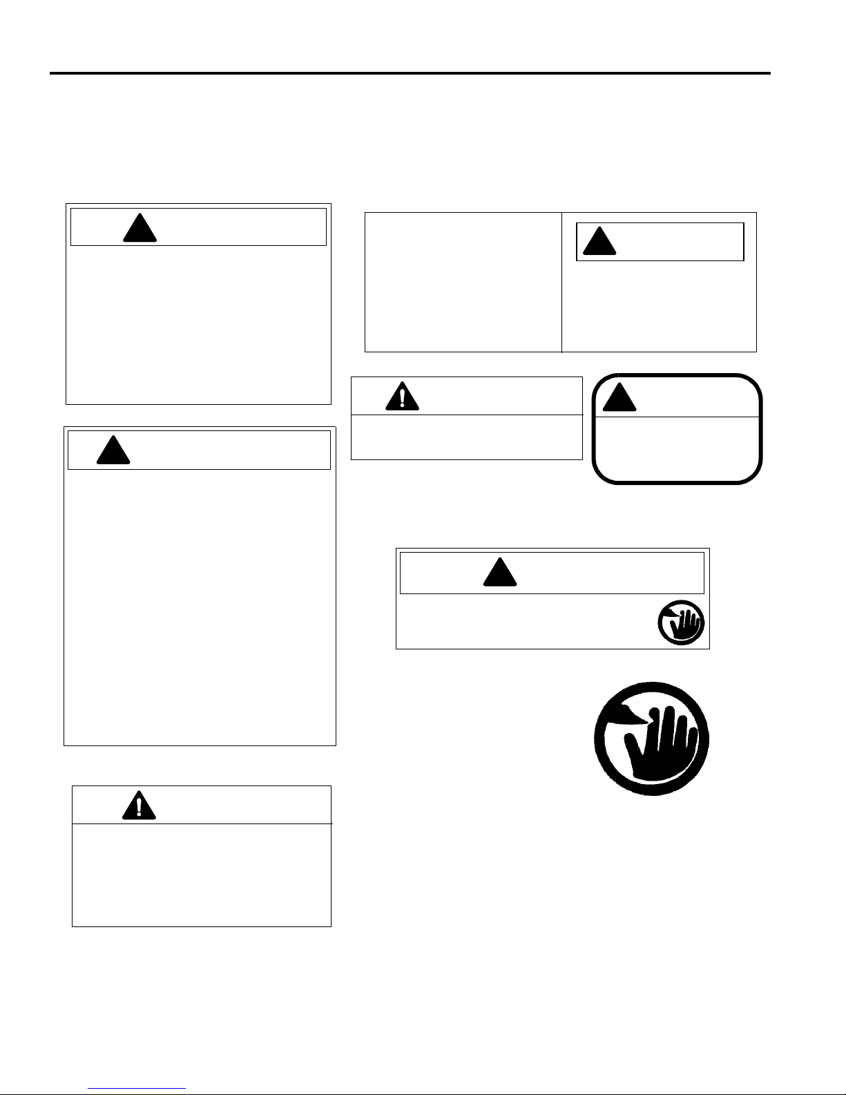
3.1 DECALS __ __ __ _________________ ______________________________ ____________
Familiarize yourself with the decals, they are critical to the safe operation of the mower.
REPLACE DAMAGED DECALS IMMEDIATELY.
8
Page 9
INITIAL INSPECTION 4
!
!
4 INITIAL INSPECTION
4.1 GENERAL ______________ __ ___ ________________ _____________________________
The set-up and testing of the unit should always be
performed by a trained technician, familiar with the
operation of the equipment.
Read each instruction completely and make sure you
understand it before procee ding with the assembly. Stay
alert for potential hazards and obey all safety
precautions.
The RIGHT , LEFT, FRONT and REAR of the machine are
referenced from the operator’s seat, facing forward.
Accessories not included with this product must be
ordered separately. See instructions provided with
accessory for installation and parts.
CAUTION
Do not attempt to operate the machine unless
you are familiar with this type of equipment and
know how to operate all controls correctly.
This machine is shipped assembled. After unpacking,
perform the initial insp ection, operating checks , and test
the Operator Presence Control (OPC) .
4.2 INITIAL INSPECTION ______________ ___ ________________ ________________ ___ ___
CAUTION
The initial inspection should be performed only when the engine is off and all fluids are cold.
Disengage all drives, engage parking brake, stop engine and disconnect spark plug wire.
1. Perform a visual inspection o f th e e ntir e uni t, loo k for
signs of wear, loose hardware, and componen ts that
may have been damaged during transport.
2. Inspect paint and decals for damage or scratches.
Decals provide important operating and safety
information. Replace all missing or hard to read
decals.
3. Check that the engine oil level is at the full level
mark with the engine cold.
4. Visually check for fuel or oil leaks.
5. Inspect lube points for proper lubrication.
9
Page 10
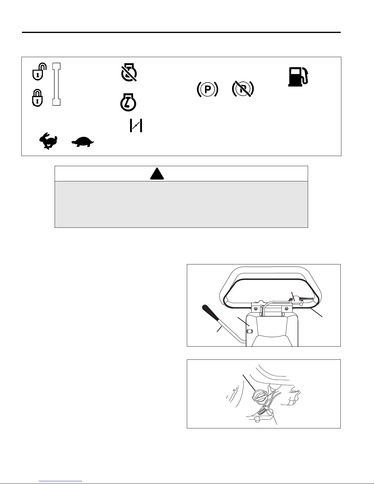
5 CONTROLS
O.P.C. Unlock
O.P.C. Lock
Engaged Disengaged
Parking Brake
Fuel
Gasoline
Choke
Engine Off
Engine Run
Fast Slow
Throttle
!
N
D
P
C
B
A
J
D
5 CONTROLS
5.1 ICONS_____________ __ ___ ________________ ________________ _________________
WARNING
Never attempt to operate the machine unless you have read the Safety and Operation
Manual, the Par ts and Ma intenance Manual, the engi ne manua l and k now how to operate
all controls correctly.
Familiarize yourself with the icons shown above and what they represent. Learn the
location and purpose of all the controls before operating this mower.
5.2 CONTROLS ______________________________________________________________
A. Parking Brake – Used whenever the mower is left
unattended or as a service brake while transporting.
B. Paddle Throttle – Controls the spe ed of the engine
when OPC Bail is enga ged. Push (+) side of lev er to
increase engine speed. Push (-) side of lever to
decrease engine speed.
C. O.P.C. Bail – Engaging bai l increases eng ine speed
which engages the centrifugal clutch. Release bail
to return engine to idle. The bail must be
disengaged to start the engine.
D. Engine Switch – The engine switch enables and
disables the ignition system. The engine switch
must be in the ON position for the engine to run.
Turning the engine switch to the OFF position s tops
the engine.
OFF
ON
Figure 5A
10
Figure 5B
Page 11

E. Choke Lever - The choke lever opens and closes
!
!
ON
OFF
E
F
G
H
G
1
G
2
H
1
H
2
the choke valve in the carburetor. The CLOSED
position enriches the fuel mixture for starting a cold
engine. The OPEN position provide s the correct fuel
mixture for operation after starting, and for res tarting
a warm engine.
F. Fuel Valve Lever - The fuel valve ope ns and closes
the connection between the fuel tank and the
carburetor. The fuel valve lever must be in the ON
position for the engine to run. When the engine is
not in use, leave the fuel valve lever in the OFF
position to prevent ca rburetor floo ding and to r educe
the possibility of fuel leakage.
Note: Before tipping mower back for adjustments,
the fuel lever must be moved to the OFF position to
prevent fuel from leaking into the crankcase.
CONTROLS 5
Figure 5C
G. Traction Clutch Lever - Point lever forward (G
disengage traction drive and allow drum to “freewheel”. Point lever to the back (G
H. Reel Clutch Lever - Poin t lever up (H
the reel drive mecha nism. Point lever down (H
disengage the reel.
) to engage.
1
) to engage
1
2
2
) to
) to
WARNING
To prevent bodily injury or property damage,
never engage the reel or traction clutch levers
while the engine is running or the O.P.C. bail is
engaged.
DANGER
Keep hands and feet away from the cutting unit to
prevent serious cuts.
J. E-Stop - Used to stop the engine. Push switch
down to disable engine ignition, pull up for normal
operation.
Figure 5D
11
Page 12

6 OPERATION
!
!
6 OPERATION
6.1 DAILY INSPECTION_________________________ _________________ ______________
2. Check the fuel supply and crankcase oil level. All
CAUTION
The daily inspection should be performed only when
the engine is off and all fluids are cold. Disengage all
drives, engage parking brake, stop engine and
disconnect spark plug wire.
fluids must be at the full mark.
3. Make sure the mower is adjusted to the required
cutting height.
4. Make sure the machine is lubricated and the
transport tires are properly inflated.
1. Perform a visual inspection o f th e e ntir e uni t, loo k for
signs of wear, loose hardware, missing or damaged
components. Check for fuel or oil leaks.
5. Check the O.P.C. system.
6.2 OPERATOR PRESENCE CONTROL (O.P.C.)____________________________________
1. The O.P.C. system is intended to protect the operator
and others from in jury by stopping the reel an d drive
mechanism as soon as the operator releases the
O.P.C. bail. T he unit is also equippe d with an eng ine
stop (E-Stop) switch that will stop the engine from the
operator’s position.
WARNING
Never operate equip ment with the O. P.C. system
disconnected or malfunctioning. Do not
disconnect or bypass any switch.
2. To test the system:
a. Place mower on the kickstand.
b. Disengage the reel clutch lever (E).
3. Start the engine.
a. Slide bail to the left adn engage OPC Bail.
b. Engine speed will increase, the drive mechanism
will engage and the wheels will begin to turn.
c. Release the O.P.C. bail. The bail must
disengage, engine spee d retur n to i dle an d dri ve
mechanism must stop.
d. Push E-Stop switch down. Engine must stop
immediately.
4. If the drive mechanism engages before the O.P.C.
bail is engaged or the d rive mechanism continue to
turn after the O.P.C. bail is releas ed; s top t he eng ine
immediately and have the system repaired.
12
Page 13
OPERATION 6
!
!
!
6.3 OPERATING PROCEDURES_________________________________________________
CAUTION
To help prevent injury, always wear safety glasses, leather work shoes or boots, a hard hat, and ear protection.
Long hair, loose clothing or jewelry may get tangled in moving parts.
1. Under no circumstances should the engine be
started with operator or bystanders standing in front
of the reel.
2. Never run the engine in an enclosed area.
3. Keep hands and feet away from moving parts and
cutting units. If possible, do not make adjustments with
the engine running.
4. Do not operate mower or attachments with loose,
damaged or missing components. Whenever
possible mow when grass is dry.
5. First mow in a test area to become thoroughly
familiar with the operation of the mower and control
levers.
Note:T o prevent damage to the reel and bedknife never
operate the reels when they are not cutting grass.
Excessive friction and heat will develop between the
bedknife and reel and damage the cutting edge.
6. Study the area to determine the best and safest
operating procedure. Consider the height of the
grass, type of terrain, and condition of the surface.
Each condition will require certain adjustments or
precautions. Only use accessories and attachm ents
approved by Jacobsen.
10. Disengage the reel clutch when crossing paths or
roadways. Look out for traffic.
11. Stop and inspect the equipment for damage
immediately after striking an obstruction or if the
machine begins to vibrate abnormally. Have the
equipment repaired before resuming operation.
WARNING
Before you clean, adjust, or repair this
equipment, always d isengage all drives, engage
parking brake, stop engine and remove spark
plug wire to prevent injuries.
12. Slow down and use extra care on hillsides. Use
caution when operating near drop offs.
13. Look behind an d down before bac king up to be sure
of a clear path. Use care when approaching blind
corners, shrubs, trees or other objects that may
obscure vision.
14. Never use your hands to clean cutting units. U se a
brush to remove grass clippings from blades.
Blades are extremely sha rp and can cause serious
injuries
7. Be aware of mower discharge direction and never
direct discharge of material toward bystanders.
Never allow anyone near the machine while in
operation. The owner/operator is responsible for
injuries inflicted to bystanders and/or damage to
their property.
CAUTION
Before mowing, pick up all debris such as rocks, toys
and wire which can be thrown by the machine. Enter a
new area cautiously. Always operate at speeds that
allow you to have complete control of the mower.
8. Use discretion when mowing near gravel areas
(roadway, parking areas, cart paths, etc.). Stones
discharged from the mower may cause serious
injuries to bystanders and/or damage the
equipment.
9. Disengage the reel clutch to stop blades when not
mowing.
13
Page 14
6 OPERATION
!
!
OFF
ON
D
ON
OFF
E
F
N
D
P
C
B
A
G
H
G
1
G
2
H
1
H
2
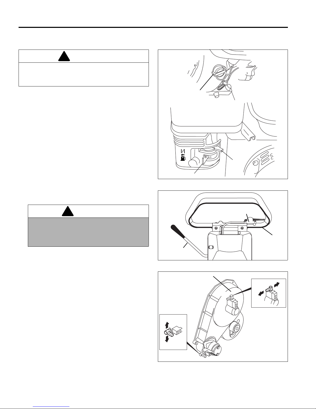
6.4 STARTING/STOPPING ENGINE ______________________________________________
CAUTION
Always start and stop the engine when the mower is
on level ground. Keep feet away from blade when
starting engine.
Starting
1. Check oil level and fuel supply then open fuel valve
lever (F).
2. Move the choke lever (E) to the “CLOSED” position.
3. Set engine switch (D) to “ON”.
4. Make certain the O.P.C. ba il (C) is disengaged and
the parking brake (A) is engaged.
5. Select desired position for traction clutch lever (G)
and reel clutch lever (H).
To cu t - engage traction clutch (G
).
(H
1
To transport - engage traction clutch (G
disengage reel clutch (H
).
2
) and reel clutch
1
) and
1
WARNING
To prevent bodily injury or property damage,
never engage the traction or reel clutch lever
while the engine is running or the O.P.C. bail is
engaged.
6. Start the engine. Do not allow the cord to “snap”
back into the starter. Do not tilt the mower back
when starting.
7. When engine starts, move choke lever (F) to the
“OPEN” position. Intermittent choking may be
required while engine is cold.
8. Allow engine to warm up gradually.
Stopping
1. To stop the engine, release the O.P.C. bail (C), and
set engine switch (D) to “OFF” position. Close fuel
shutoff valve (F).
Figure 6A
Figure 6B
2. Engage parking brake (A).
14
Figure 6C
Page 15
OPERATION 6
!
G
H
G
1
G
2
H
1
H
2
!
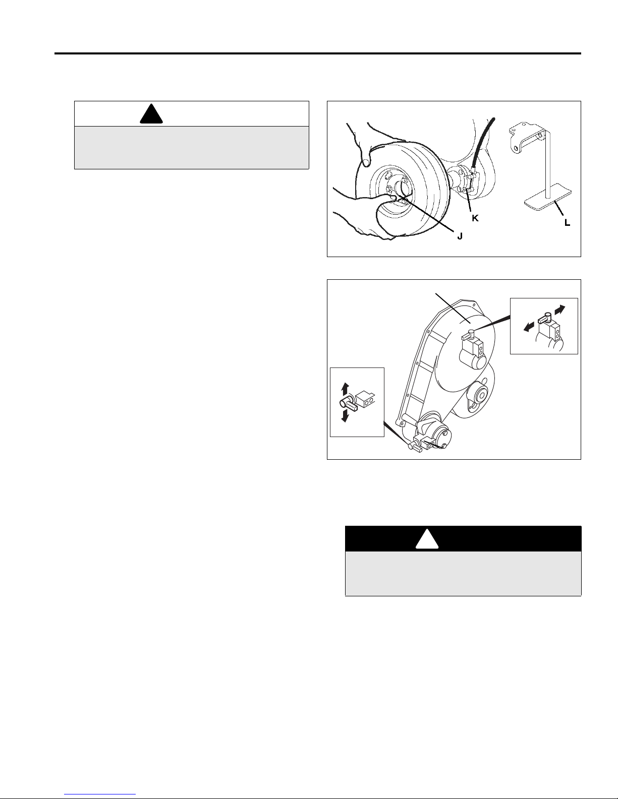
6.5 TRANSPORT WHEELS (OPTIONAL KIT) _______________________________________
WARNING
Always stop the engine and disengage the drive
levers before installing or removing the transport
wheels.
1. Push and hold the kickstand against the ground then
pull the mower hand le ba ck until the mower rests on
the stand (L).
2. To remove wheels, press retaining clip (K) away
from hub and pull wheel off hub.
3. To install wheels, press retaining clip (K), place
wheel on hub and turn the wheel backwards until
studs on back of whe el line up with ho les in hub (J).
Push wheel in and release clip.
Figure 6D
4. Always disengage reel clutch l ever (H
traction clutch lever (G
mower more than a few feet.
5. Push the mower forward off the kickstand, start the
engine and engage the O.P.C. bail.
6. When using a vehicle to transport the mowe r, apply
parking brake, stop engine and close fuel shut-off
valve.
7. Recommended Tire Pressure: 6 to 8 psi (41 to 55
kPa).
) prior to transporting the
1
) and engage
2
Figure 6E
6.6 GRASS CATCHER _________________________________________________________
1. When the basket is about two thirds (2/3) full of grass
clippings, move the mower off the green.
2. Sto p on a f lat surfa ce, disen gage all dr ives and s top
the engine.
3. Remove and empty the grass clippings from the
mower.
To prevent serious injury, always stop the engine
and disengage all drives before emptying grass
catcher.
DANGER
6.7 WEIGHT BARS ____________________________________________________________
1. This mower was designed to be used with a Jacob-
2. When using a front roller, the weights can be
sen Turf Groomer®. The weight bars located above
the grass deflector should be removed when using a
groomer.
removed to compensate for soft greens and other
mowing conditions.
e. As the mower crosses the edge of the green,
lower the mower head to the ground and
proceed across the green in a straight line. While
mowing support the hand le so the handle tubes
do not contact the handle stops. Allowing the
handle to rest on the handle stops or pushing the
handle up into the sto ps m ay resu lt i n an uneven
cut.
15
Page 16
6 OPERATION
!
1
2
3
4
5
6.8 MOWING_________________________________________________________________
1. Stop the engine. Place mower on kickstand and
remove the transport wheels.
2. Engage the reel clutch lever (H
clutch lever (G
kickstand. Start the engine.
). Push the mower forward off
1
) and the traction
1
WARNING
To prevent bodily injury or property damage,
never engage the reel or traction clutch levers
while the engine is running or the O.P.C. bail is
engaged.
3. Position mower slightly off the green.
a. Adjust engine speed (B) to provide a safe,
comfort able walking speed.
b. Push handle down to lift t he mower head above
the grass then engage the O.P.C. bail (C).
c. As the mower crosses the edge of the green,
lower the mower head to the ground and
proceed across the green in a straight line.
d. When the opposite side of the green i s reached,
push down of the handle to lift the mower head
without disengaging the O .P.C. bail a nd proceed
off the green to turn around or simply release
O.P.C. bail and turn around.
6. Use caution while operating on hillside and dropoffs.
Figure 6F
Second
Mowing
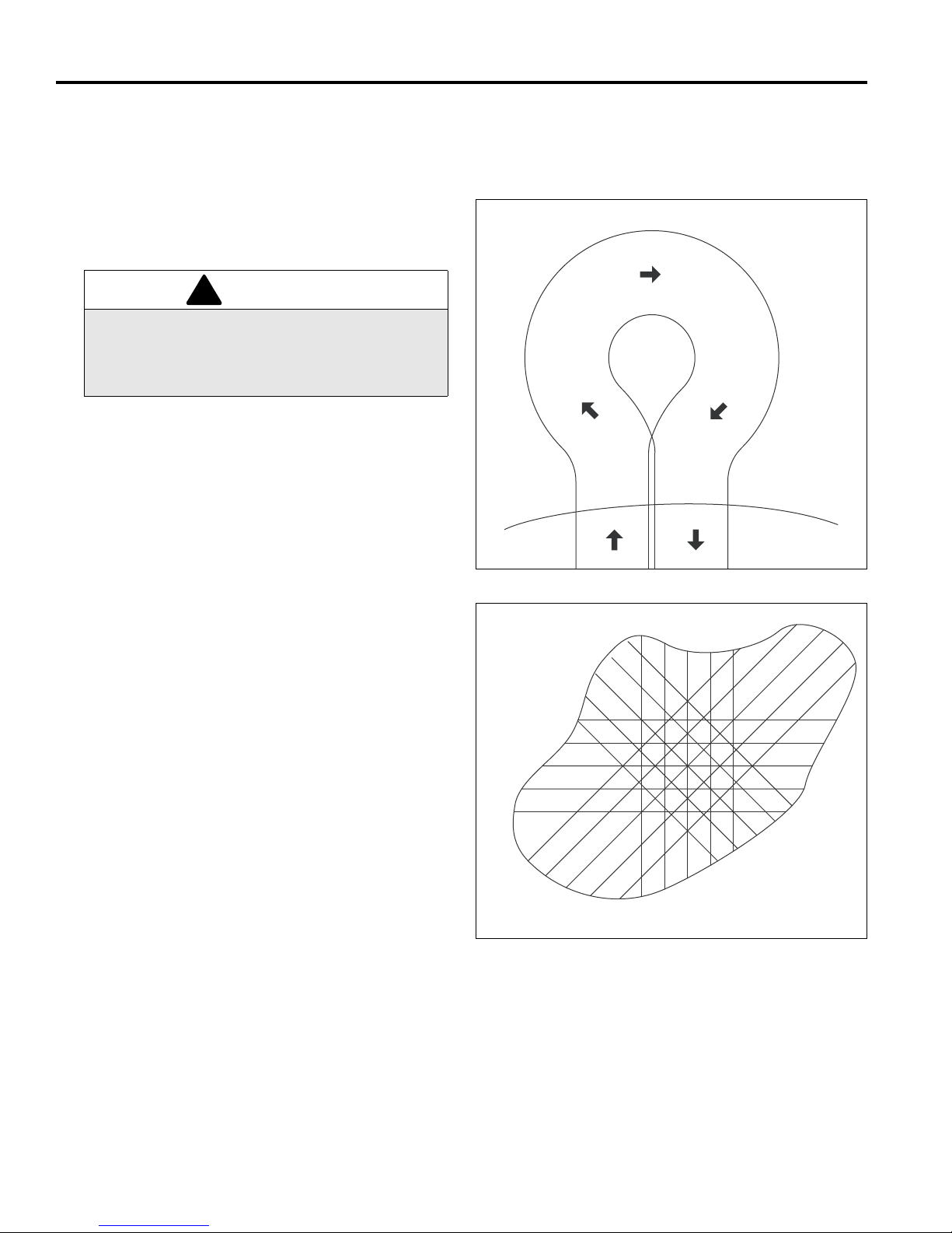
e. To turn to the right, start by turning mower slightly
to the left (2). When the mower has moved
approximately 1/2 its own width to the left, swing
it around quickly to t he right (3 and 4), guiding
the mower with your right hand. This method
makes it possible to turn around quickly with very
few steps. [Figure 6F]
Note:T o prevent damage to the reel and bedknife never
operate the reels when they are not cutting grass.
Excessive friction and heat will develop between the
bedknife and reel and damage the cutting edge.
4. To assure complete , even cutting , overlap swaths by
1 to 2 in., (25 to 50 mm), then make one or more
passes around the perimeter of the green to clean
ragged edges and separate the putting green
surface from the apron.
5. For a more even playing surface and neater
appearance, alter the mowing pattern each time a
green is mowed. The patterns s hown in Figure 6G
are suggestions only, the operator or course
superintendant can arrange patterns to suit each
green.
First
Mowing
Fourth
Mowing
Third
Mowing
Figure 6G
16
Page 17

OPERATION 6
!
6.9 DAILY MAINTENANCE______________________________________________________
1. Park the mower on a flat, level surface. Engage
parking brake and stop the engine.
2. Grease and lubricate all points if required.
3. To prevent fires, wash the mower after each use.
a. Use only fresh water for cleaning your
equipment.
Note: Use of salt water or affluent water has been
known to encourage rust and corrosion of metal parts
resulting in premature deterioration or failure.
Damage of this nature is not covered b y the factory
warranty.
b. Do not use high pressure spray.
c. Do not spray water into the cooling fins or the
engine air intake.
Note: Do not wash a hot or running engine. Use
compressed air to clean the engine.
4. Fill fuel tank at the end of each operating day. Do
not fill above the fuel strainer shoulder. Close fuel
valve when unit is not in use.
Use clean, fresh, unleaded gasoline, 86 octane
minimum.
Handle fuel with care - it is highly flammable. Use an
approved container, the spout must fit inside the fuel filler
neck. Avoid using cans and funnels to transfer fuel.
WARNING
Never remove the fuel cap f rom the fuel tank, or add
fuel, when the engine is r un ning or while the engi ne is
hot.
Do not smoke when handling fuel. Never fill or drain
the fuel tank indoors.
Do not spill fuel and clean spilled fuel imm edi ate ly.
Never handle or store fuel containers near an open
flame or any device that may create sparks and ig nite
the fuel or fuel vapors.
Be sure to reinstall and tighten fuel cap securely.
5. Store fuel according to local, state or federal
ordinances and recommendations from your fuel
supplier.
6. Check the engine oil at the start and end of each
day, before starting the engine. If the oil level is low,
remove the oil filler cap and add oil as require d. Do
not overfill.
17
Page 18
7 ADJUSTMENTS
!
!
!
°
°
1/32”
(0.8 mm)
7 ADJUSTMENTS
7.1 GENERAL____________ ___ __ ______________________________ _________________
2. Replace, do not adjust, worn or damaged
WARNING
Before you adjust, clean, or repair this equipment,
always disengage all drives, engage parking brake
and stop engine to prevent serious injury.
Whenever performing maintenance other than
carburetor adjustments, remove the spark plug wire
and place the wire away from the plug to prevent
accidental starting and bodily injury.
1. Adjustments and maintenance should always be performed by a qualified technician. If proper adjustment
cannot be made, contact an authorized Jacobsen
Dealer.
7.2 REEL TO BEDKNIFE _______________________________________________________
(Pre-adjustment Check)
1. Check the reel bearings for end play or radial play. If
there is any abnormal movem ent of the reel, up an d
down or side to side, adjust or replace components
as needed.
components.
3. Long hair, jewelry or loose fitting clothing may get
tangled in moving parts.
CAUTION
Be careful to prevent entrapment of the hands and
fingers between moving and fixed components of the
machine.
4. Do not change governor settings or overspeed the
engine.
5. A lifting hook has been provided between the
engine and the clutch m echanism so the mower can
be safely hoisted onto a workbench.
5. The reel must be parallel to the bedknife. An
improperly adjusted reel will lose its sharp edges
prematurely and may result in serious damage to
the reel and bedknife.
6. Grass conditions will also affect the adjustment.
CAUTION
To prevent personal injury and damage to the cutting
edges, handle the reel with extreme care.
2. Inspect the reel blades and bedknife to insu re good
sharp edges without bends or nicks.
a. The cutting edges of the reel blades and bed-
knife must be sharp, free of burrs and show no
signs of rounding off.
b. The bedknife and bedknife backing must be
securely tightened. The bedknife must be
straight and sharp.
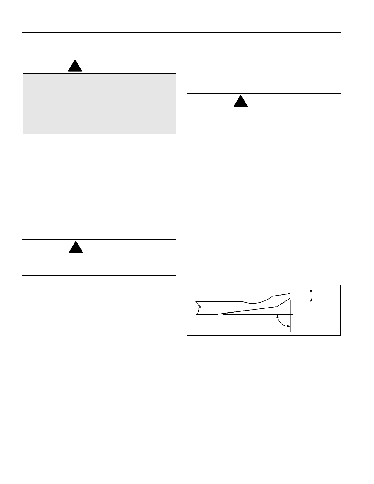
c. A flat surface of at least 1/32 in. (0.8 mm)
minimum must be maintained on the front face of
the bedknife. Use a s tandar d f lat file to dr es s th e
bedknife.
3. If wear or damage is beyond the point where the
reel or bedknife can be corrected by the lapping
process, they must be reground.
4. Proper reel-to-bedknife ad justment is critical. A ga p
of 0.001 to 0.003” (0.025 to 0.076 mm) must be
maintained across the entire length of the reel and
bedknife.
a. Dry, sparse conditions wi ll req uire a wid er gap t o
prevent heat buildup and damage to the reel and
bedknife.
b. High quality grass with a good mois ture content
requires a closer gap (near zero).
Figure 7A
18
Page 19
ADJUSTMENTS 7
A
B
Rotation
Leading Edge
!
H
J
K
Brake Band
1.50”
(38 mm)
7.3 BEDKNIFE ADJUSTER _____________________________________________________
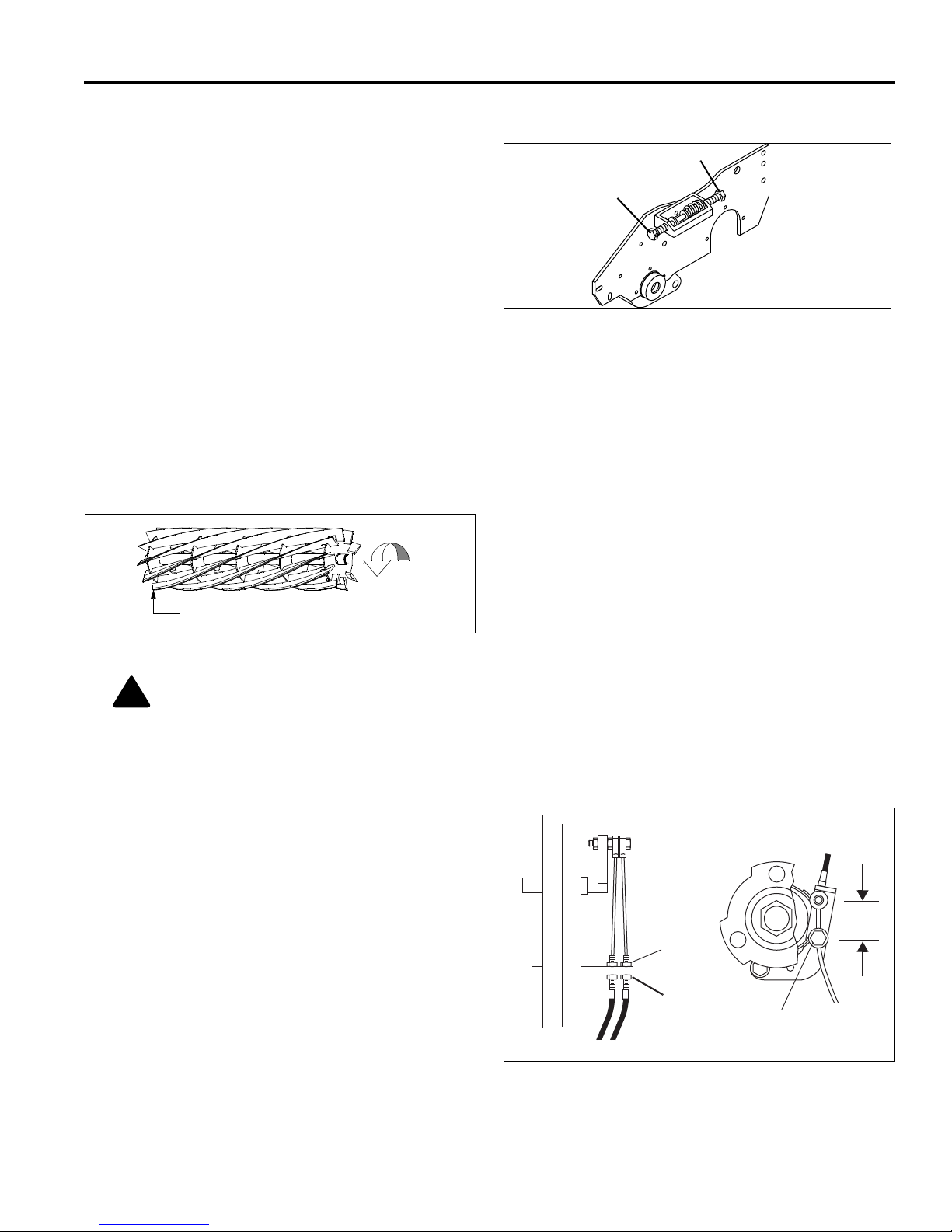
1. Adjuster (A) is used to increase or decrease the
spring load on the bedk nife. Adjuster (B) is used to
move the bedknife to the reel or away from the reel.
2. Once the spring is totally collapsed as a result of
many adjustments, the bedknife cannot be moved.
Back-off adjuster (A) before adjusting (B).
3. For most applications, com press the spring to 1 in .,
(25 mm).
Figure 7B
7.4 BEDKNIFE _______________________________________________________________
1. Read Section 7.2 before making the adjustment.
2. Start adjustment at the leading edge of the reel,
followed by the trailing e nd. The leading end of the
reel blade is the en d that passes over the bedknife
first during normal rotation.
Figure 7C
CAUTION: Ha ndle the reel with extreme care
to prevent personal injur y and damage to the
cutting edges.
3. Turn adjuster (B) clockwise to bring the bedknife
closer to the reel or counterclockwise to back the
bedknife away from the reel.
a. Slide a feeler gauge or shim s tock .0 01 -.00 3 in.,
(.025 - .075 mm) between t he reel bl ade and th e
bedknife. Do not turn the reel.
b. Adjust the trailing end of the reel in the same
manner, then recheck the adjustment at the
leading end.
c. When the reel and bedknife are properly
adjuster, the reel will spin freely and will cut a
piece of newspaper along the full length of the
reel when the paper is held at 90° to the
bedknife.
7.5 BRAKE __________________________________________________________________
A properly adjusted brake requires 10 lb. pull at top of
brake lever to engage and must have 1.50” (38 mm)
center to center when released.
1. Minor adjustments are made at the handle. Loosen
nut (H), turn nut (J) to adjust the brake cable, then
tighten nut (H).
2. If adjustments cannot be made at the handle,
remove the transport wheel and make the
adjustment at the brake band.
3. Loosen screw (K) and pull cable to obtain desired
brake tension. Tighten screw (K). Readj ust (H) and
(J).
Figure 7D
19
Page 20
7 ADJUSTMENTS
L
M
N
O
P
Q
CAUTION: To prevent permanent damage to
the belt, do not twist, fold, bend or overtighten
the belt.
!
A
F
B
C
D
E
K
L
M
H
G
N
F
7.6 CUTTING HEIGHT _________________________________________________________
Note: Make sure the bedknife is properly adjusted before
setting the cutting height. (See Section 7.4)
1. Push kickstand down and tip mower back on it’s handle. Do not leave the mower tipped back for an
extended length of time or oil may migrate into the
combustion chamber.
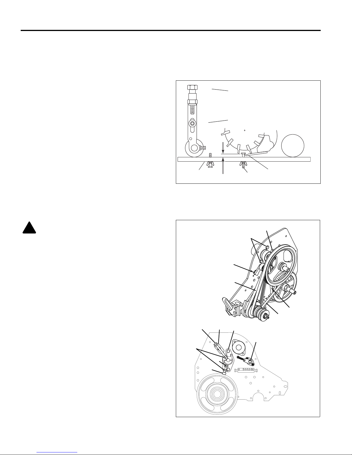
2. Loosen nuts (M) on both sides just enou gh to allow
knob (L) to raise the front roller or Turf Groomer.
Raise both sides an equal amount.
3. Set gauge screw (P) to the desired cutting height
(O). Measure from the gauge bar (N) to the
underside of the screw head (P) then tighten wing
nut to lock the adjustment.
4. Place gauge bar between front roller and traction
roller, near the outer end of the rollers.
5. Slide screw head over bedknife (Q) a nd adjust knob
(L) so roller just contacts the gauge ba r. Tighten nut
(M).
6. Repeat Steps 4 and 5 on the opposite end of the
reel then tighten n uts (M). Recheck and r eadjust the
cutting height if necessary.
Figure 7E
7.7 BELT ADJUSTMENT _______________________________________________________
.
1. Belt (A) is tensioned by a sp ring loaded idler pulley
(F). No adjustment is necessary.
2. To adjust belt (B) or (C), loosely assembl e 5/16-18 x
3-1/4” hex head screw (K) through tension bracket
(P), bearing bracket and 5/16-18 hex nut (N).
Assemble 5/16-18 x 1” hex head screw (L) and 5/
16-18 hex nut (N) to bottom of bear ing bracket (G).
Loosen nuts (E).
a. Place bedknife gauge bar (H) on top of roller and
b. Tighten screw (K) until belt (C) deflects 9/64” (3.5
c. Tighten nuts (E) and remov e 5/16-18 x 1” screw
Note: 5/16-18 x 3-1/4” sc rew (K) and upper nut (N)
can be left in place after the adjustment procedure
is complete without affecting operation.
3. Place hardware (L and N) in a safe place for future
adjustments.
under screw (L). Tighten scre w (L) until belt (B)
deflects 1/10” (2.5 mm) with 12.2 ~ 15.2 lb (5.5 ~
7.4 kg) load applied at midshipman.
mm) with 3.5 ~ 6.3 lb (1.59 ~ 2.86 kg) load
applied at midshipman.
(L) and lower nut (N)
Figure 7F
20
Page 21
ADJUSTMENTS 7
Y
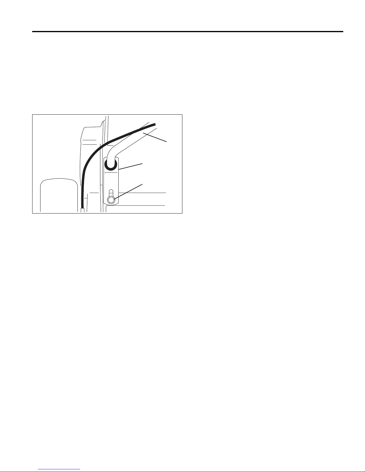
7.8 HANDLE _________________________________________________________________
1. To adjust the angle of the handle bar (Y), loosen
screw (W) on both side s of the mo wer and ad ju st th e
handle bar to the desired position.
2. After adjusting handle bar, adjust bracket (X) so that
the handle bar jus t rests on the bottom of the slot in
bracket. Tighten screw (W).
X
W
Figure 7G
21
Page 22
7 ADJUSTMENTS
4.6
8.8
10.9
12.9
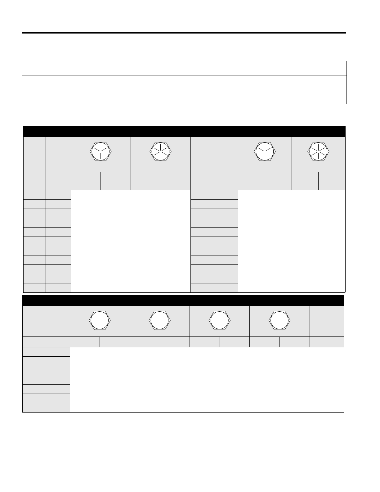
7.9 TORQUE SPECIFICATION___________________________________________________
CAUTION
All torque values included in these charts are approximate and are for reference only. Use of these torque values is
at your sole risk. Jacobsen is not responsible for any loss, claim, or damage arising from the use of these charts.
Extreme caution should always be used when using any torque value.
Jacobsen uses Grade 5 P lated bolts as standard, unless othe rwise noted. For tightenin g plated bolts, use the value
given for lubricated.
AMERICAN NATIONAL STANDARD FASTENERS
SIZE UNITS GRADE 5 GRADE 8 SIZE UNITS GRADE 5 GRADE 8
Lubricated Dry Lubricated Dry Lubri-
cated
#6-32 in-lb (Nm) – 20 (2.3) – – 7/16-14 ft-lb (Nm) 37 (50.1) 50 (67.8) 53 (71.8) 70 (94.9)
#8-32 in-lb (Nm) – 24 (2.7) – 30 (3.4) 7/16-20 ft-lb (Nm) 42 (56.9) 55 (74.6) 59 (80.0) 78 (105)
#10-24 in-lb (Nm) – 35 (4.0) – 45 (5.1) 1/2-13 ft-lb (Nm) 57 (77.2) 75 (101) 80 (108) 107 (145)
#10-32 in-lb (Nm) – 40 (4.5) – 50 (5.7) 1/2-20 ft-lb (Nm) 64 (86.7) 85 (115) 90 (122) 120 (162)
#12-24 in-lb (Nm) – 50 (5.7) – 65 (7.3) 9/16-12 ft-lb (Nm) 82 (111) 109 (148) 115 (156) 154 (209)
1/4-20 in-lb (Nm) 75 (8.4) 100 (11.3) 107 (12.1) 143 (16.1) 9/16-18 ft-lb (Nm) 92 (124) 122 (165) 129 (174) 172 (233)
1/4-28 in-lb (Nm) 85 (9.6) 115 (13.0) 120 (13.5) 163 (18.4) 5/8-11 ft-lb (Nm) 113 (153) 151 (204) 159 (215) 211 (286)
5/16-18 in-lb (Nm) 157 (17.7) 210 (23.7) 220 (24.8) 305 (34.4) 5/8-18 ft-lb (Nm) 128 (173) 170 (230) 180 (244) 240 (325)
5/16-24 in-lb (Nm) 173 (19.5) 230 (26.0) 245 (27.6) 325 (36.7) 3/4-10 ft-lb (Nm) 200 (271) 266 (360) 282 (382) 376 (509)
3/8-16 ft-lb (Nm) 23 (31.1) 31 (42.0) 32 (43.3) 44 (59.6) 3/4-16 ft-lb (Nm) 223 (302) 298 404 315 (427) 420 (569)
3/8-24 ft-lb (Nm) 26 (35.2) 35 (47.4) 37 (50.1) 50 (67.8) 7/8-14 ft-lb (Nm) 355 (481) 473 (641) 500 (678) 668 (905)
Dry Lubri-
cated
Dry
SIZE UNITS
Lubricated Dry Lubricated Dry Lubricated Dry Lubricated Dry
M4 Nm (in-lb) – – – – – – 3.83 (34) 5.11 (45) 2.0 (18)
M5 Nm (in-lb) 1.80 (16) 2.40 (21) 4.63 (41) 6.18 (54) 6.63 (59) 8.84 (78) 7.75 (68) 10.3 (910 4.0 (35)
M6 Nm (in-lb) 3.05 (27) 4.07 (36) 7.87 (69) 10.5 (93) 11.3 (102) 15.0 (133) 13.2 (117) 17.6 (156) 6.8 (60)
M8 Nm (in-lb) 7.41 (65) 9.98 (88) 19.1 (69) 25.5 (226) 27.3 (241) 36.5 (323) 32.0 (283) 42.6 (377) 17.0 (150)
M10 Nm (ft-lb) 14.7 (11) 19.6 (14) 37.8 (29) 50.5 (37) 54.1 (40) 72.2 (53) 63.3 (46) 84.4 (62) 33.9 (25)
M12 Nm (ft-lb) 25.6 (19) 34.1 (25) 66.0 (48) 88.0 (65) 94.5 (70) 125 (92) 110 (81) 147 (108) 61.0 (45)
M14 Nm (ft-lb) 40.8 (30) 54.3 (40) 105 (77) 140 (103) 150 (110) 200 (147) 175 (129) 234 (172) 94.9 (70)
22
METRIC FASTENERS
Non Critical
Fasteners
into
Aluminum
Page 23

MAINTENANCE 8
!
!
!
8 MAINTENANCE
8.1 GENERAL ______________ __ ___ ________________ _____________________________
d. Keep all fluids at their proper levels.
WARNING
Before you adjust, clean, or repair this equipment,
always disengage all drives, engage parking brake
and stop engine to prevent serious injury.
Whenever performing maintenance other than
carburetor adjustments, remove the spark plug wire
and place the wire away from the plug to prevent
accidental starting and bodily injury.
1. Adjustment and maintenance should always be performed by a qualified technician. If proper adjustments
cannot be made, contact an Authorized Jacobsen
Dealer.
2. Inspect the equipment on a regular basis, establish a
maintenance schedule and keep detailed records.
a. Keep the equipment clean.
b. Keep all moving parts properly adjusted and lubri-
cated.
c. Replace worn or damaged parts before operating
the machine.
e. Keep shields in place and all hardware securely
fastened.
f. Keep tires properly inflated.
3. Long hair, jewelry or loose fitting clothing may get
tangled in moving parts.
CAUTION: Be careful to prevent entrapment
of the hands and fing ers betwe en moving an d
fixed components of the machine
4. Use the illustrations in the Parts Catalog as reference
for the disassembly and reassembly of components.
5. Recycle or dispose of all hazardous materials (fuel,
lubricants, etc.) according to local, state or federal
regulations.
6. Do not change governor settings or overspeed the
engine.
7. A lifting hook has been provided between the engine
and the clutch mechanism so the mower can be safely
hoisted onto a workbench
8.2 ENGINE _________________________________________________________________
IMPORTANT: A separate Engine Manual, prepared by
the engine manufacturer, is supplied with this machine.
Read the engine manual carefully until you are familiar
with the operation and maintenance of the engine.
Proper attention to the engine manufacturer’s
directions will assure maximum service life of the
engine. To order replacement engine manuals contact
the engine manufacturer.
The proper break-in of a new engine can make a
considerable difference to the performance and life of the
engine.
Note: The mower is designed to operate and cut most
efficiently at the preset governor setting. Do not change the
engine governor settings or overspeed the engine.
During the break-in period, Jacobsen recommends the
following:
1. Operate machine modestly for the first 25 hours at
reduced engine speed.
2. Avoid full throttle starts and rapid acceleration.
3. Allow the engine to reach operating temperature before
operating at full load.
4. Change the engine oil after the first 20 hours of
operation.
5. Refer to Section 10.2 and Engine Manual for
specific maintenance intervals.
23
Page 24
8 MAINTENANCE
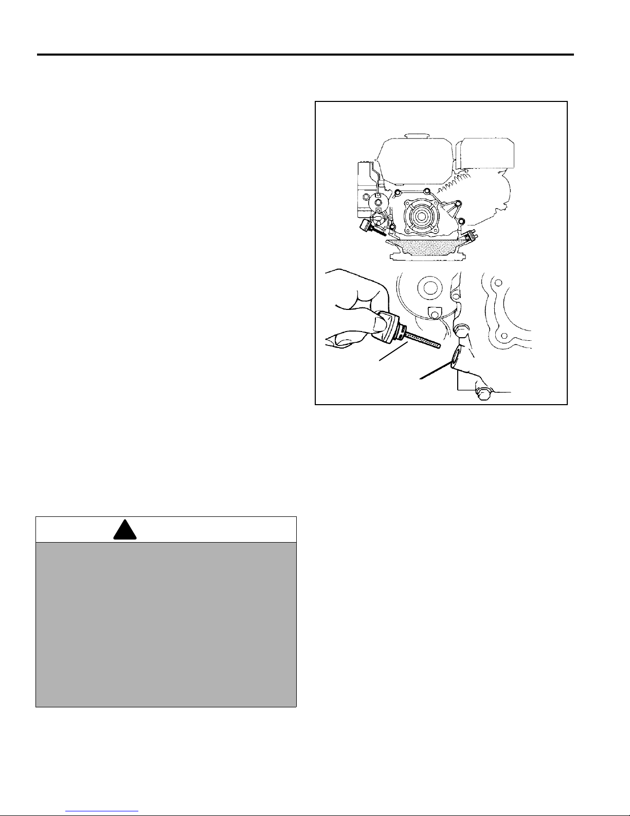
Upper Oil Level
Oil Filler Cap
!
8.3 ENGINE OIL ______________________________________________________________
Check the engine oil at the start of each day, before starting
the engine. If the oil level is low , remove oil filler cap and add
oil as required.
Perform initial oil change after the first 20 hours of operation.
Change oil every 100 hours thereafter.
See the engine manufacturer’s Owners’s Manual for
detailed service information.
After adding or changing oil, start and run engine at idle with
all drives disengaged for 30 seconds. Shut engine off. Wait
30 seconds and check oil level. Add oil to bring up to FULL
mark on dipstick.
Use only SAE 10W30 engine oils with API classification
SG.SF/CC.CD
Figure 8A
8.4 FUEL____________________________________________________________________
Handle fuel with care - it is highly flammable. Use an
approved container, the spout must fit inside the fuel filler
neck. Avoid using cans and funnels to transfer fuel.
WARNING
Never remove the fuel cap f rom the fuel tank, or add
fuel, when the engine is r un ning or while the engi ne is
hot.
Do not smoke when handling fuel. Never fill or drain
the fuel tank indoors.
Do not spill fuel and clean spilled fuel imm edi ate ly.
Never handle or store fuel containers near an open
flame or any device that may create sparks and ig nite
the fuel or fuel vapors.
Be sure to reinstall and tighten fuel cap securely.
• Never overfill or allow the tank to become empty.
• Use clean, fresh, regular grade, unleaded gasoline
minimum 86 Octane.
• See engine manual before using oxygenated (blended)
fuel.
• Do not fill above the fuel filler neck.
• Store fuel according to local, state or federal
ordinances and recommendations from your fuel
supplier.
24
Page 25
MAINTENANCE 8
!
8.5 TIRES ___________________________________________________________________
1. Keep tires properly inflated to prolo ng tire l ife. Che ck
pressure only when the tires are cool.
2. Use an accurate, low pressure tire gauge. 6 - 8 psi
(41.3-551. kPa)
CAUTION: Unless you have the proper
training, tools and experience, DO NOT
attempt to mount a tire on a rim. Improper
mounting can produc e an explosion that may
result in serious injury.
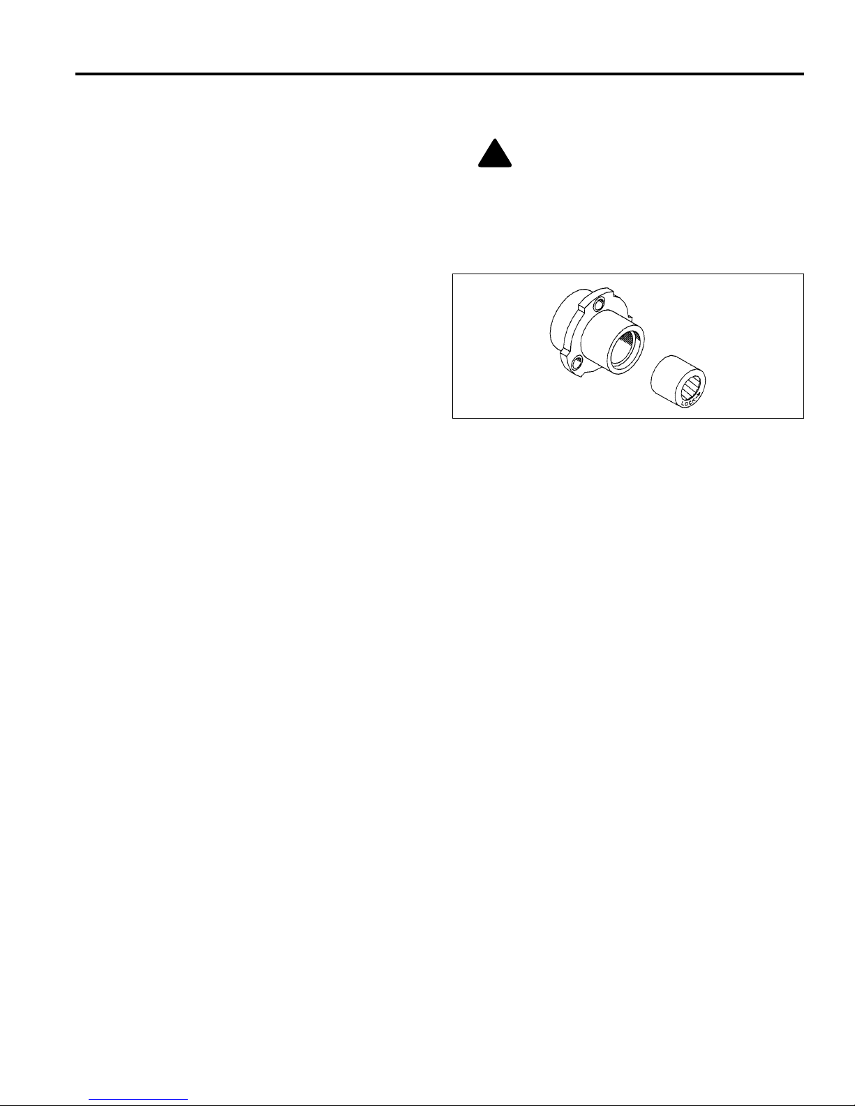
8.6 WHEEL BEARING _________ ___ ________________ ________________ _____________
The bearing has the word LOCK and an arrow stamped
on the face. When replacing the bearing, make
absolutely certain that the bearing is being installed in the
proper direction or rotation.
For the Right wheel, install the bearing with the
“LOCK➨" arrow to the Outside of the bearing housing.
For the Left wheel, install the bearing with the “LOCK➨"
arrow to the Inside of the housing.
Figure 8B
8.7 BACKLAPPING AND GRINDING______________________________________________
Check for damage to the bedknife and reel blades.
Refer to (Section 7.2).
1. Determine if backlapping or gri nding will restore the
proper cutting edge.
2. For optimum performance use a bedknife grinder to
touch-up the blade then reas semble and adjust the
bedknife to the reel as described in (Section 7.2).
3. Remove shaft cover from right side of reel and
assemble a 3/8-24 bolt and locknut to the end of th e
shaft.
a. Apply lapping compound with a long handle
brush along the entire length of the reel, (180 grit
is recommended, Section 2.6).
b. Continue lapping and at the s ame time make a
fine adjustment on the reel and bedknife until
there is a uniform clearanc e along th e full le ngth
of the cutting edges.
4. Carefully and thoroughly remove all lapping
compound from reel and bedknife before running
the reel in forward direction.
25
Page 26

8 MAINTENANCE
!
8.8 STORAGE________________________________________________________________
General
1. Wash the mower thoroughly and lubricate.
2. Repair and paint damaged or exposed metal.
3. Inspect the mower, tighten all hardware, replace
worn or damaged components. Refurbish the reel
and bedknife.
4. Back the bedknife away from the reel and apply a
light coat of r ust preventative oil on the reel blades
and bedknife,
5. Sto re the mower on kickstand so the loa d is off the
tires. The front roller or Turf Groomer should be
resting on a wood board.
6. Keep the mower and all its accessories clean, dry
and protected from the elements during storage.
Never store equipment wi th fuel in the tank inside a
building where fumes may reach an open flame or
spark.
7. Do not store near flammable debris.
Engine
3. Fill the fuel tank with fresh fuel. Open fuel shut off
valve.
4. Remove all oil from the cutting edges. Readjust
reel-to-bedknife and cutting height.
5. Support mower so traction drum is off the ground
and disengage reel clutch. Start the engine and
operate at 1/2 throttle. Allow enough time for the
engine to become properly warmed and lubricated.
NOTE: T he traction drum will rotate with e ngine running
at 1/2 throttle.
WARNING
Never operate the engine without proper ventilation;
exhaust fumes can be fatal if inhaled.
1. While the engine is warm, remove drain plu g, drain
the oil from the crankcase. Ins tall drai n pl ug a nd refi ll
with fresh oil. Torque drain plug to 22 ft. lb. (30 Nm).
2. Clean exterior of engine. Paint the exposed metal or
apply a light coat of rust preventative oil.
3. To prevent the build-up of gu m residues and vanish
films, fill the tank with stabilized fuel. Use an antioxidant fuel conditioner, such STA-BIL®. Read and
follow the instructions on the container.
4. Operate the engine for about 5 minute s to distribute
the treated fuel. Stop the engine, close the fuel shutoff valve and let the engine cool. Drain fuel.
5. Remove the spark plug and pour about one ounce
of SAE 30 oil into the cylinder. Crank engine slowly
by hand to distribute oil over the cylinder wall.
Replace the spark plug.
6. Pull the starter rope slowly until resistance is felt.
Continue pulling unti l the notch on the s tarter pulley
aligns with the hole on the recoil starter. At this
point, the intake and exhaust valves are closed.
After Storage
1. Check or service the fuel filter and air cleaner.
2. Check oil level in the engine crankcase.
26
Page 27

TROUBLESHOOTING 9
9 TROUBLESHOOTING
9.1 GENERAL ______________ __ ___ ________________ _____________________________
The troubleshooting chart below lists basic problems that may occur during start-up and operation. F or more detailed
information, contact your area Jacobsen Dealer.
Symptoms Possible Causes Action
Engine will not start.
Engine hard to start
or runs poorly,
looses power or
stalls.
Mower does not
react to O.P.C.
Lever
Reels do not cut, or
cut unevenly
1. Choke in wrong position 1. See Engine Manual
2. Empty fuel tank or dirty fuel 2. Drain and refill fuel tank with fresh, clean fuel
3. Fuel Shut-off valve closed 3. Open fuel shut -off valve
4. Engine / Spark Plug 4. See Engine Manual
5. Engine switch off 5. Turn engine switch t o On
1. Choke in wrong position 1. See Engine Manual
2. Dirty or incorrect fuel 2. Refill with proper grade, clean fuel
3. Loose Wiring 3. Check spark plug wire
4. Air intake plugged 4. Clean air intake and air cleaner
5. Vent in fuel cap plugged 5. Clean fuel cap
1. Parking brake engaged 1. Disengage parking brake
2. Traction clutch disengaged 2. Engage traction clutch
3. Reel clutch disengaged 3. Engage reel clutch
4. Broken Belt 4. Check and replace belts as needed
1. Reel to bedknife not adjusted 1. Adjust Reel to Bedknife
2. Reel clutch disengaged 2. Engage reel clutch
27
Page 28
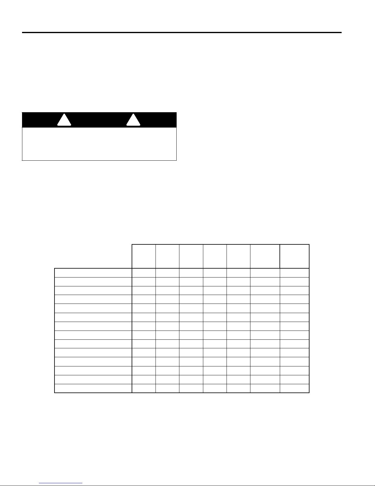
10 MAINTENANCE & LUBRICATION CHARTS
!
!
10 MAINTENANCE & LUBRICATION CHARTS
10.1 GENERAL________________________________________________________________
The mower was designed for minimum lubricati on. Over
greasing will produce high loads on the bearings and
engine; thereby reducing the performance of the
machine.
All maintenance intervals must be performed more
frequently when operating in extremely dusty conditions.
WARNING
3. For smooth operation of pivot points and other
friction points, apply several drops of SAE 30 oil
every 50 hours or as required.
4. To lubricate points (L
and L7), remove left transport
6
wheel.
Remove nut (A) from end of shaft and pull wheel hub
(D) off. Remove collar (B) and bushing (C) then pack
bearing (L
) with lithium grease.
7
Before you clean, adjust, or repair this equipment,
disengage all drives, lower implements to the ground,
engage parking brake, stop engine and disconnect spark
plug wire to prevent injuries.
Remove mounting bracket (E) to gain access to
fitting (L
). Turn the traction drum if pulley (F) is
6
blocking the fitting then insert grease gun through
hole and carefully apply grease.
1. Always clean grease fittings before and after lubrication.
2. Lubricate with grease that meets or exceeds NLGI
Grade 2 LB specifications. Apply grease with a
5. To lubricate point (L
one pump of grease to fitting on end of shaft.
), remove cover (G) and apply
10
manual grease gun and fill slowly until grease
begins to seep out. Do not use compressed air.
10.2 MAINTENANCE CHART _____________________________ _______________________
Recommended Service and Lubrication Intervals
Every
8-10
Hours
Air Cleaner
Every
20
Hours
IC
Combustion Chamber
Engine Oil
IR* R I
Fuel Line
Fuel Strainer
Spark Plug
Valve Clearance
Grease Locations
- L
L
1
4
- L
L
5
6
L
7
- L
L
8
9
L
10
L
11
LLII
A - Add or Adjust C - Clean I - Inspect L- Lubricate R - Replace AR - As Required
* Indicates initial service for new machines.
I Engine Oil - See Section 8.3
II Manual grease gun with NLGI Grade 2 (Service Class LB).
III Lubriplate
®
marine grease, Jacobsen Part No. 5001581
Every
50
Hours
Every
100
Hours
Every
250
Hours
Yearly Lubricant
C
R - 2yrs
C
A/R
A
L II
LLIII
L III
L II
L II
Type
28
Page 29
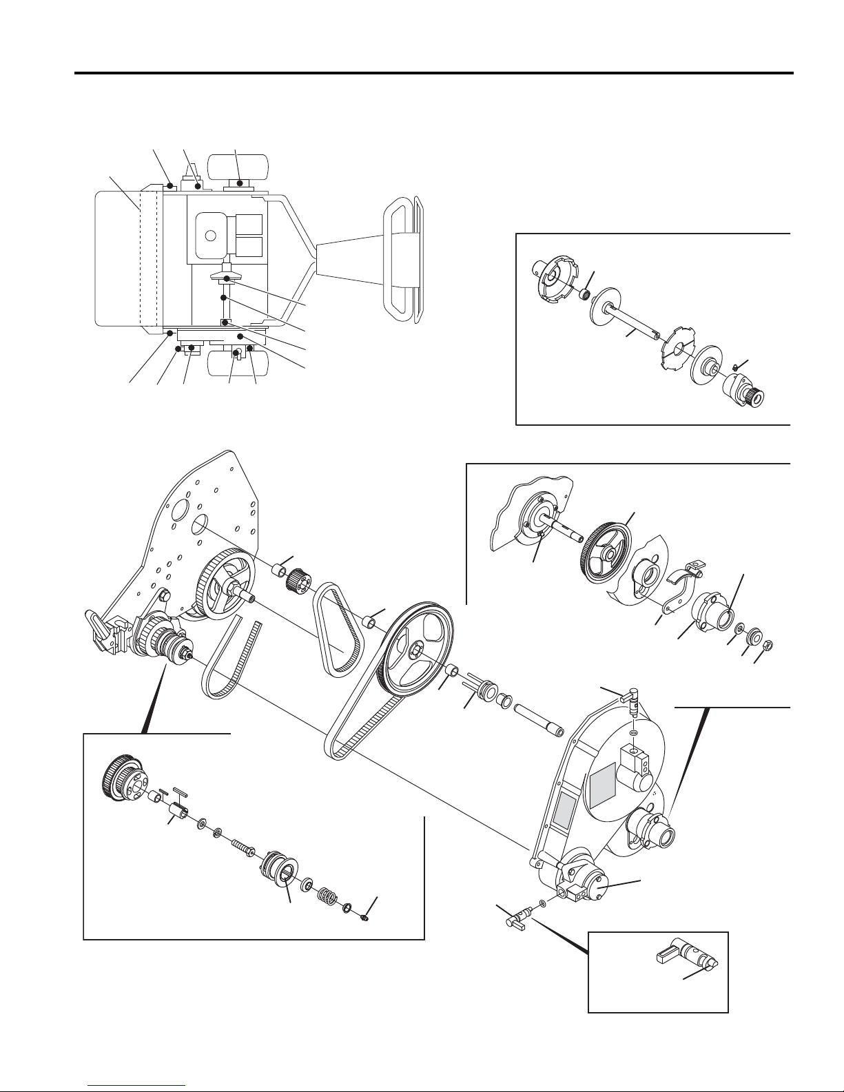
MAINTENANCE & LUBRICATION CHARTS 10
L
14
L
14
L
13
Æ
Æ
●
F
C
D
G
B
A
L
9
L
10
E
●
●
● - NLGI #2 Grease
Æ - Lubriplate
¨
Marine Grease
L
12
L
8
Æ
●
●
●
●
L
11
●
L
11-12
Apply Lubricant
L
6
L
7
Æ
●
L
5
●
L
3
L
4
L
5
L
6
L
7
L
8
L
9
L
10
L
11
L12L
13
L
14
L
2
L
2
L
1
10.3 LUBRICATION CHART______________________________________________________
29
Page 30

Naročilo delov
1. Na naročilnico napišite polno ime in točen naslov.
2. Pojasnite kam in kako naj bo pošiljka dostavljena.
3. Navedite številko in ime proizvoda ter serijsko
številko, ki je izpisana na ploščici za ime oziroma se rijsko številko na vaši napravi.
4. Na naročilnico napišite želeno koli čino delov in njihov
opis, kot je naveden na seznamu delov.
V primeru uporabe delov in priključkov, ki jih ni odobilo podjetje Jacobsen, garancija ne velja.
Kazalo
1 Varnost
1.1 Varnost pri delu................................................. 4
1.2 Pomembna varnostna navodila ........................5
2 Specifikacije
2.1 Identifikacija proizvoda ..................................... 6
2.2 Motor .............................. .................... ...............6
2.3 Kosilnica ...........................................................6
2.4 Pogon in diferencial ..........................................7
2.5 Teže ............................... ................................... 7
2.6 Dodatna oprema in dokumentacija ...................7
3 Nalepke
3.1 Nalepke............................................................. 8
4Začetni pregled
4.1 Splošno............................................................. 9
4.2 Začetni pregled .................................................9
5Krmila
5.1 Ikone............................................................... 10
5.2 Controls ..........................................................10
6 Delovanje
6.1 Dnevni pregled................................................ 12
6.2 Nadzor prisotnosti uporabnika (N.P.U.) ..........12
6.3 Delovni postopki ................... ...... ....... ...... .......13
6.4 Vklop/izklop motorja ........................................14
6.5 Transportna kolesa (Dodoatna oprema) .........15
6.6 Lovilec za travo ...............................................15
6.7 Uteži ............................... .................... .............15
6.8 Košnja ............................ ................................. 16
6.9 Dnevno vzdrževanje .......................................17
5. Naročilnico pošljite oziroma prinesite pooblaščenemu zastopniku Jacobsen.
6. Ob prejemu preglejte vse pošiljke. Če so deli
poškodovani oziroma manjk aj o, pr i dost av lj alc u
vložite pritožbo preden pošiljko sprejmete.
7. Materiala ne vračajte brez pisnega pojasnila, kjer
navedite, katere dele vračate. stroški transporta
morajo biti plačani vnaprej.
7 Prilagoditve
7.1 Splošno .......................................................... 18
7.2 Vreteno in spodnji nož .................................... 18
7.3 Regulator spodnjeg a noža ............................. 19
7.4 Spodnji nož .................................................... 19
7.5 Zavora ............................................................ 19
7.6 Višina košnje .................................................. 20
7.7 Nastavitev jermenov ....................................... 20
7.8 Ročaj .............................................................. 21
7.9 Specifikacija vijakov ........................................ 22
8 Vzdrževanje
8.1 Splošno .......................................................... 23
8.2 Motor .............................................................. 23
8.3 Motorno olje ................................................... 24
8.4 Gorivo ........................ ................... .................. 24
8.5 Kolesa ............................................................ 25
8.6 Nosilci koles .................................................... 25
8.7 Brušenje in ostrenje ....................................... 25
8.8 Skladiščenje ................................................... 26
9 Odpravljanje težav
9.1 Splošno .......................................................... 27
10 Tabele za vzdrževanje in podmazovanje
10.1 Splošno .......................................................... 28
10.2 Tabela za vzdrževanje ................................... 28
10.3 Tabela za podmazovanje ............................... 29
11 Seznam delo v
11.1 Seznam delov ................................................ 30
© Copyright 2005, Textron Inc. “Vse pravice pridržane, vkljušno s pravico do
2
reprodukcije tega materiala v kakršni koli obliki.”
LITHO V ZDA. 4-2006
Page 31

Predlagane smernic za zaloge
Da bi vaša oprema delovala dol go in dobro, podjetje Jacob sen predlaga, da im ate pogosto rabljene dele ve dno na
zalogi. Priložili smo tudi številke delov za dodatno opremo in pomoč pri delu.
Če želite naročiti opremo:
1. Na naročilnico napišite polno ime in točen naslov.
2. Pojasnite kam in kako naj se oprema dostavi:
× UPS × Običajna pošta
× Naslednji dan × Drugi dan
3. Na naročilnico napišite želeno koli čino delov in njihov
opis, kot je naveden na seznamu delo.
4. Naročilnico pošljite oziroma prinesite pooblaščenemu zastopniku Jacobsen.
Potrošni material
Kos Št. dela Opis Kos Št. dela. Opis
2810713 Jermen med motorjem in vretenom 2811363 Jermen med zavoro in vretenom
2811071 Zavorni jermen 5000141 26” Spodnji nož za dolgo travo
5000098 18” Spodnji nož z nizkim profilom 5002888 18” Poseben spodnji nož
503478 22” Spodnji nož z nizkim profilom 503477 22” Spodnji nož z visokim profilom
5002887 22” Poseben spodnji nož 164056 Zavorni jermen
Dodatni material
Kos Št dela. O pis
4131586 Tehnični priročnik
Kos Opis
Servisni priročnik
Video za učenje
Uporaba priročnika
Kratice
N/D - Ni dobavljivo posebej. na voljo je le v osnovnem kompletu oziroma ob napravi.
SŠ -Za dosego pravilnih nastavitev je potrebno spremenljivo število oziroma količina.
Simboli kot na primer I, poleg številke dela , opozarjajo na dodatno op ombo, ki vsebuje dodatne po membne
informacije za naročanje del ov.
Priporočeni deli
Priporočeni deli so del i, ki jih je mogoče dobiti v paketu ozirom a poleg druge komponente. Te dele lahko naročite
posebej oziroma poleg osnovne naprave.
Del Št. dela. Kos Opis Serijske številke/opombe
l 1 123456 1 Nastavek, Ventil Posamezni del
2 789012 1 Ventil, Dvigalka Vsebuje dela 2 in 3
3 345678 1 • Ročica Element, vključen k delu 2
4 N/D 1 • Tesnilni kit Nedobavljiv element, vključen k delu 2
5 901234 1 Vijak, 1/4-20 x 2” Šestkotna glava
3
Page 32

1 SAFETY
!
1 SAFETY
1.1 VARNOST PRI DELU ___________ _________________ ___________________________
OPOZORILO
NEPOZNAVANJE NAVODIL ALI NEPRAVILNA UPORABA JE LAHKO NEVARNA.
Seznanite se s pravilno uporabo vseh vodil in kje se nahajajo. Neizkušenega upravljalca mora pred uporabo z
opremo seznaniti nekdo, ki napravo dobro pozna.
1. Varnost je odvisna od zavedanja, skrbi in prev idno sti
tistih, ki upravljajo ali vzdržujejo napravo. Nikoli ne
zaupajte upravljanja naprave mladoletni osebi.
2. Vaša odgovornost je, da preberete ta priročnik in
vse publikacije, povezane z napravo. Odgovornost
lastnika je, da pojasni navodila upravljalcu, v
primeru da le-ta ne razume jezika, v katerem so
napisana.
3. Naučite se pravilne uporabe opreme, kje se
nahajajo vodila in čemu so namenjena. Delo brez
poznavanja opreme lahko pripelje do nesreče.
4. Upravljanja ali vzdrževanja naprave oziroma
priključkov ne dovolite nikomur, ki z njo ni ustrezno
seznanjen ter z opremo in navodili nima izkušenj
oziroma je pod vplivom alkohola ali mamil.
5. Nosite ustrezno zaščitno opremo in obleko, da
zavarujete glavo, oči, ušesa, roke in noge. Dolgi
lasje, ohlapna obl ačila ali nakit se lahko zapl etejo v
premične dele naprave. Z napravo delajte le pod
dobro umetno svetlobo ali podnevi.
6. Preglejte teren in tako določite, katere priključke
boste uporablili, da bo delo potekalo varno in
nemoteno. Uporabljajte le dovoljene priključke in
dodatno opremo.
10. Iznosa materiala nikoli ne usmerjajte neposredno
proti opazovalcem, ravno tako ne dovolite, da se
kdo zadržuje v bližini naprave. Lastnik oziroma
upravljalec lahko preprečita oziroma sta odgovorna
za lastne poškodbe, poškodbe opazovalcev in
materialno škodo.
11. Nikoli ne delajte z naprav o, ki ni tehnično brez hibna,
je brez varnostnih nalepk oziroma varovala, in kjer
ščiti, odbojniki in druga zaščitna oprema niso
pravilno nameščeni.
12. Nikoli ne izklopite ali onemogočite stikala.
13. Ogljikov monoksid v izpušnih plinih je lahko
smrtonosen, kadar pride v pljuča. Nikoli ne
zaganjajte motorja v nezračenih prostorih.
14. Gorivo je močno vnetljivo. Ravnajte previdno.
15. Motor naj bo čist. Pustite, da se ohladi in vedno
zaprite dovod goriva ter izklopite vžigalno svečko
preden napravo uskladiščite. Ne hranite naprave v
bližini odprtega ognja ali vnetljivih snovi.
16. Postavi te napravo na ravno po vršino, zaus tavite vse
pogone in vključite ročno zavoro preden poženete
motor.
17. Lokalna pravila lahko omejujejo starost upravljalca.
7. Bodite pozorni na luknje v terenu in druge prikrite
nevarnosti.
8. Preglejte področje, na katerem boste uporabljali
napravo. Pred začetkom dela poberite kamenje.
Bodite pozorni na ovire nad glavo (nizke veje
dreves, električne žice, ipd.) in pod zemljo (zalivalne
naprave, cevi, korenine dreves, ipd). Na novo
področje napredujte previdno. Bodite pozorni na
skrite nevarnosti.
9. Ne vozite potnikov. Opazovalci in domače živali naj
bodo na primerni varnostni razdalji.
Napravo uporabljajte in vzdržujte, kot je prikazano v tem priročniku. Naprava je namenjena posebnim vrstam
trave. Naprave ne uporabljajte na neravnem terenu ali v dolgi travi.
4
18. Napravo vodite po površini brega (horizontalno), ne
premikajte je v ver tikalni smeri. Ne delajte na m okri
travi.
19. Vedno delajte s tako hitrostjo, ki vam omogoča
popoln nadzor nad napravo. Pazite na korake.
Trdno držite vodilo in hodite, nikoli ne tecite.
20. Pred čiščenjem, nastavljanjem ali popravilom
naprave ustavite motor, izklopite vžigalno svečko,
vžigalno kapo pa umakni te daleč stran, da ne pride
do neželenega vžiga.
Page 33
SAFETY 1
!
!
!
1.2 POMEMBNA VARNOSTNA NAVODILA _ _______________________________________
Ta opozorilni znak svari pred varnostnimi tveganji.
NEVARNOST – Ta znak opozarja na neposredno nevarnost, katere posledica je smrt ali resne poškodbe, če
nevarnosti ne preprečimo.
OPOZORILO – Ta znak opozarja na možno nevarnost, katere posledica je lahko smrt ali resne poškodbe, če
nevarnosti ne preprečimo.
POZOR – Ta znak op ozarja na možno nevar nost, katere posledic a je lahko la žja pošk odba ali ma terialna šk oda, če
nevarnosti ne preprečimo. Svari tudi pred nepravilno uporabo.
Zaradi ja snejšega prikaza nekatere ilustracije v tem priročniku prikazujejo odstranjene zaščitne dele in odprte pokrove.
Naprave pod nobenim pogojem ne uporabljajte brez nameščenih delov.
OPOZORILO
Mehanizem za nadzo r pri so tnos ti uprav lj al ca bo iz klj u čil vrete no in pogonsko
gred, kadar bo upravljalec sprostil stikalo mehanizma.
Da bi bil upravljalec in drugi ljudje varni pred poškodbami, naprave ne
uporabljajte, če je mehanizem za nadzor prisotnosti upravljalca (MNPU)
okvarjen ali izključen.
OPOZORILO
1. Preden zaradi kakršnih koli razlogov zapustite operaterjevo mesto:
a. Izključite vse pogone.
b. Vključite parkirno zavoro.
c. Ustavite motor.
2. Rok, nog in obleke ne približuj te gibljivim de lom. Počakajte, da p reneha
vsako gibanje, preden napravo očistite, nastavljate oziroma popravljate.
3. V delovnem področju stroja se ne smejo zadrževati ljudje in živali.
4. Zaustavite oziroma blokirajte kolesa, če se naprava nahaja na strmini.
5. Naprave za košenje ne uporabljajte, če zaščite izpusta niso ustrezno
nameščene.
Z upoštevanjem teh navodil boste podaljšali življenjsko dobo vaše naprave in ohranili njeno največjo učinkovitost.
Natavitve in popravila naj vedno izvaja pooblaščeni tehnik.
Kadar potrebujete d odatno informacijo ali storitev, se obrnite na pooblaščenega zastopnika pod jetja Jacobsen, ki je
seznanjen z najnovejšimi postopki za servisiranje naprave in lahko zagotovi hitro storitev. V primeru uporabe delov in
dodatkov, ki niso originalni oziroma odobreni s stani podjetja Jacobsen, garancija ne velja.
5
Page 34
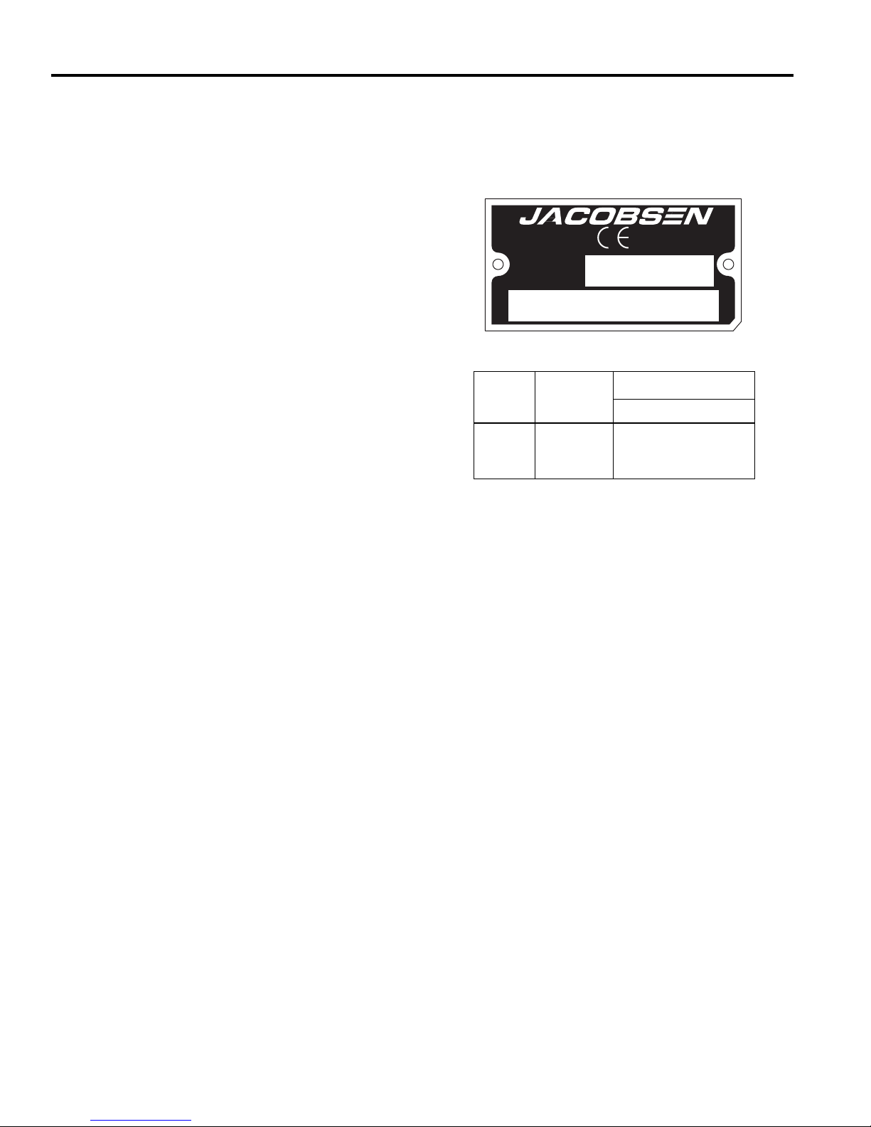
2 SPECIFICATIONS
63281 1601
2006
2 SPECIFICATIONS
2.1 IDENTIFIKACIJA PROI ZV ODA __________________________ __ __ ___ ______________
63281............................ 18 in. (457 mm) Greens King 518A
z nadzornim sistemom
Kadar naročate rezervne dele oziroma potrebujete
informacije o storitvah, vedno navedite serijsko številko.
InCommand™ , Honda 4.0 K.M.
bencinskim motorjem in vretenom z
11 rezili.
63282............................ 22 in. (559 mm) Greens King 522A
z nadzornim sistemom
InCommand™ , Honda 4.0 K.M.
CHARLOTTE, NC
YEAR OF
PRODUCTION:
A Textron Company
MADE IN U.S.A.
®
bencinskim motorjem in vretenom z
11 rezili.
63285............................ 26 in. (660 mm) Greens King 526A
z nadzornim sistemom
InCommand™ , Honda 4.0 K.M.
bencinskim motorjem in vretenom s
7 rezili.
Serijska številka ........... Serijska številka vaše naprave je
izpisana na identifikacijski ploščici,
kakršna je prikazana na sliki desno,
najaja pa se na zadnjem križnem
Proizvod
63281
63282
63285
Moč zvoka
po EEC
90
91
89
Vibracije v M/S
Roke
5.74
6.477
3.401
2
elementu.
2.2 MOTOR__________________________________________________________________
Motor................................Honda GX-120 K1Q JG2 4-taktni,
4KM (2.98 kW) pri 4000 obratih
Hitrost ..............................visoka - 3000 ± 100 obrati
nizka - 1700 ± 100 obrati
Uporabljajte čist, svež, običajen neosvinčen bencin,
vendar naj bo najmanj 86 oktanski. Kadar uporabljate
mešano gorivo, naj mešanica ne vsebuje več kot 10%
etanola.
Gorivo ..............................Običajno (neosvinčeno)
Posoda za gorivo.............0.66 Galone (2.5 litra)
Pod mobeim pogojem ne uporabljajte mešanice z
metanolom.
2.3 KOSILNICA_______________________________________________________________
Vreteno ............................7 ali 11 rezil, kaljeno visokoman-
gansko ogljikovo jeklo.
Premer vretena................5 in. (127 mm)
Širina košenja..................18-1/4 in. (457 mm), 22 in.
(559 mm), 26 in. (660 mm)
Frekvenca košenja:
7 rezil ..........................0.250 in. (6.3 mm)
11 rezil.........................0.169 in. (4.3 mm)
Višina košenja..................5/64 to 7/16 in. (2 to 11 mm)
Vretena............................ Kaljeno ogljikovo jeklo
Globok profil ...............Omogoča 5/32 in. (4 mm) rez
(Standard na 63285)
Nizek Profil .................Omogoča 7/64 in. (2.8 mm) rez
Super turnirski ............Omogoča 1/16 in. (1.6 mm) rez
(Standard na 63281, 63282)
Sklopka vretena............... Zobniška
6
Page 35

SPECIFICATIONS 2
!
2.4 POGON IN DIFFERENCIAL __________________________________________________
Kolesa (Opcija).................11 x 4 pnevmatska dvosmerna
Pritisk v pnevmatikah.......6 do 8 psi (41 do 55 kPa)
Pogon vretena..................Rebrasti Micro V jermen
Krmilo pogona..................Sinhronizirani poliretanski jermeni
s struno iz kevlarja
Redukcija na pogonu .......21.8:1
Redukcija na vretenu .......1.67:1
Sklopka pogona ...............Zobniška
Sklopka motorja ...............Centrifugalna
Potovalna hitrost ..............3.2 mph (5.14 km/h)
pri 3000 obratih
Diferencial........................Popolnoma avtomatski, pritrjen v
boben vretena
Boben motorja..................Valjana aluminijeva zlitina
2 predela:
63281..........................7-3/4 (O.D.) x 9.10 in.
(197 x 231 mm)
63282..........................7-3/4 (O.D.) x 10.97 in.
(197 x 278 mm)
63285..........................7-3/4 (O.D.) x 13.25 in.
(197 x 343 mm)
2.5 TEŽE_____________________________________________________________________
Teže: Lbs. (kg)
Teža z lovilcem, sprednjim valjem, stojalom in utežmi
63281 ............................................................210 (95)
63282 ............................................................223 (101)
63285 ............................................................272 (123)
2.6 DODATNA OPREMA IN DOKUMENTACIJA_____________________________________
Obrnite se na vašega zastopnika podjetja Jacobsen za popoln seznam dodatne opreme.
POZOR: Uporaba delov, ki jih ni odobrilo podjetje Jacobsen, lahko povzroči telesne poškodbe oziroma
okvare opreme, garancija pa v tem primeru ne velja.
Dodatna oprema
Brusilno sredstvo (180 velikost zrn) ..........................554598
Oranžna retuširna barva (12 unčni sprej).................. 554598
Krmilo.......................................................................... 68612
18 in. Lovilec za travo .................................................68122
22 in. Lovilec za travo .................................................68123
26 in. Lovilec za travo .................................................68124
22 in. Potisna ščetka....................................................68611
22 in. Ščetka prednjega valja...................................... 68610
18 in. Dvigovalnik trave...............................................68624
22 in. Dvigovalnik trave...............................................68605
26 in. Dvigovalnik trave...............................................68625
18 in. Konverzijska oprema magnetnih sp. nožev... 4131024
22 in. Konverzijska oprema magnetnih sp. nožev... 4130281
26 in. Konverzijska oprema magnetnih sp. nožev... 4131029
Kljuke za podvozje in ročaj kosilnice 518.................... 68649
Kljuke za podvozje in ročaj kosilnice 522.................... 68650
Kljuke za podvozje in ročaj kosilnice 526.................... 68651
Podvozje in ročaj......................................................... 68648
Gladki valji
18 in. z grebljico.......................................................... 68626
22 in. z grebljico.......................................................... 68530
26 in. z grebljico.......................................................... 68627
Profilirani valji
18 in. Valjano jeklo.......................................................68616
22 in. Sestavljen disk...................................................68527
22 in. Valjan aluminij....................................................68614
22 in. Valjano jeklo.......................................................68613
22 in. Segmentiran valj ................................................68673
26 in. Valjan alumini.....................................................68617
26 in. Valjano jeklo.......................................................68628
Dodatna dokumentacija
Tehnični priročnik .....................................................4131586
Video za uporabnika................................................4131596
Servisni priročnik
7
Page 36
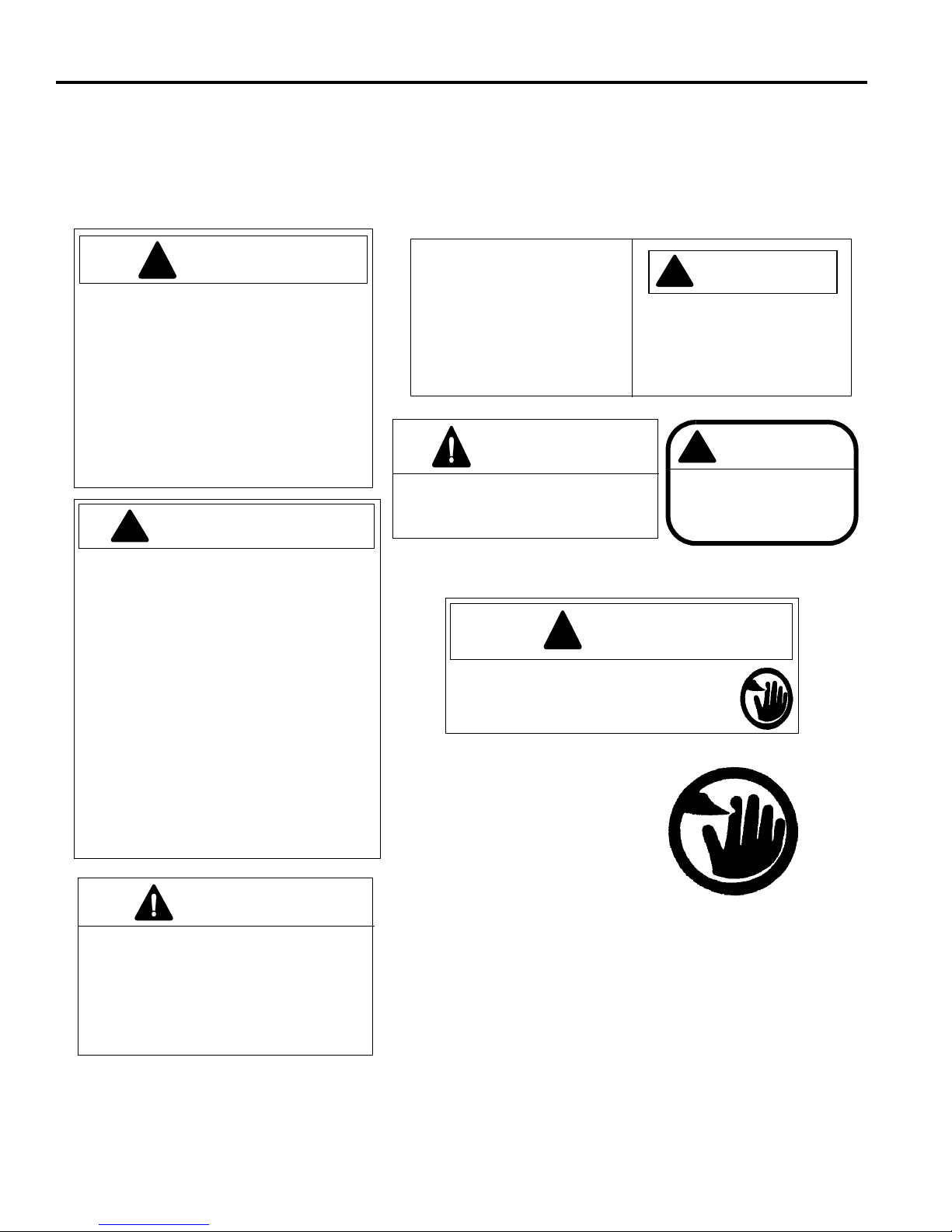
3 DECALS
!
NEVARNOST
!
POZOR
1. Zaščita naj bo na svojem mestu.
2. Kadar prilagajate nastavitve ali podmazujete, ustavite motor.
3. Če se mehanizem prenasiči, izkjučite
elektriko in ugasnite motor pred
čiščenjem.
4. Ne približujte rok, nog ali obleke
delom pod napetostjo.
5. Pred uporabo natančno preberite
navodila.
365511
1. Ne uporabljajte naprave, če niste
seznanjeni z njenim delovanjem
oziroma niste prebrali navodil za uporabo.
2. Vsa zaščita naj bo na svojem mestu in
vsi deli morajo biti čvrsto pritrjeni.
3. Ustavite napravo in ugasnite motor preden praznite posodo za travo, prilagajate nastavitve, ali napravo popravljate
oziroma razstavljate .
4. Držite roke, noge in oblačila stran od
gibljivih delov naprave.
5. Na napravi ne vozite drugih ljudi brez
ustreznega sedeža zanje.
6. Če navodil ne razumete, prosite
nekoga, da jih raztolmači.
! POZOR
340623
PRED DOLIVANJEM
GORIVA PUSTITE
NAJ SE MOTOR HLADI
PRIBL. 2 MINUTI
! POZOR
362764
POZOR
3001790
3001235
4127335
! POZOR
Model 518A 95.3 kg
Model 522A 101.2 kg
Model 526A 123.4 kg
2811102
Model 522TA 100.7 kg
Model PGM 19 84.0 kg
Model PGM 22 85.0 kg
Masa vozila:
Model TC22 101.1 kg
OPOZORILO
4146636
DA BI PREPREČILI POŠKODBE IN
NEŽELJEN VKLOP SKLOPKE, NE
PRILAGAJATE HITROSTI MOTORJA Z
ROČICO NA MOTORJU, TEMVEČ
UPORABLJAJTE ROČICO NPU IN
PEDAL ZA PLIN.
PRED ZAGONOM MOTORJA NAJ
BO ROČICA SKLOPKE VRETENA
V NEVTRALNEM POLOŽAJU
Drugi ljudje se ne smejo
zadrževati v bližini naprave.
Naprave ne uporabljajte, če
nima nameščene zaščite.
Da ne pride do hudih telesnih poškodb,
ustavite motor in izključite vreteno,
preden začnete prilagajati napravo ali
praznete posodo za travo.
3 DECALS
3.1 NALEPKE________________________ __ ___ __ ______________________________ ___
Seznanite se z nalepkami, saj so zelo pomem bne za varno delo s kosilnico. POŠKODOVANE
NALEPKE NEMUDOMA ZAMENJAJTE.
8
Page 37
INITIAL INSPECTION 4
!
!
4 INITIAL INSPECTION
4.1 SPLOŠNO ________________ _________________ ________________ _______________
Priprave in preizkušanje naprave naj vedno izvaja
izkušen tehnik, ki dobro pozna delovanje naprave.
POZOR
Vsako navodilo pr eberite do konca in se prepri čajte, da
ga v celoti razumete, preden začnete s sestavljanjem.
Pazite na možne nevarnosti in upoštevajte vsa varnostna
navodila.
DESNA, LEVA, PREDNJA in ZADNJA stran naprave so
prikazane glede na voznikov sedež, usmerjen naprej.
Dodatno opremo, ki ni dobavl jena s strojem, je potrebno
naročiti posebej. Navodila za montažo in dele dobite v
tehničnem priročniku za priključek, ki ste ga naročili.
Naprava se dobavlja sestavljena. Ko ste jo razpakirali, jo
preglejte in preizkustte delovanje ter sistem nadzora
prisotnosti upravljal ca (NPU) .
Ne uporabljajte kosilnice, če s tovrstnimi
napravami niste seznanjeni in niste prepričani,
pravilno uporabljate vsa krmila.
4.2 ZAČETNI PREGLED________________________________________________________
POZOR
Začetni pregled se izvaja, ko je motor izključen in so tekočine hladne. Izključite vse pogone, potegnite ročno zavoro,
ustavite motor in izključite vžigalno svečko.
1. Preglejte celotno napravo. Iščite znake obrabe, slabo
pritrjene dele in kom pon ente , ki bi se l ahko p oš kod ovale med transportom.
2. Preglejte zaščitni premaz in nalepke. Nalepke
vsebujejo pomembn e informacije glede delovanja i n
varnosti. Izgubljene ali slabo berljive nalepke takoj
zamenjajte.
3. Prepričajte se, da sega gladina motornega olja do
najvišje oznake, kadar je motor hladen.
4. Prepričajte se, da olje oziroma gorivo ne iztekata.
5. Prepričajte se, da je naprava na vseh mestih
ustrezno podmazana.
9
Page 38
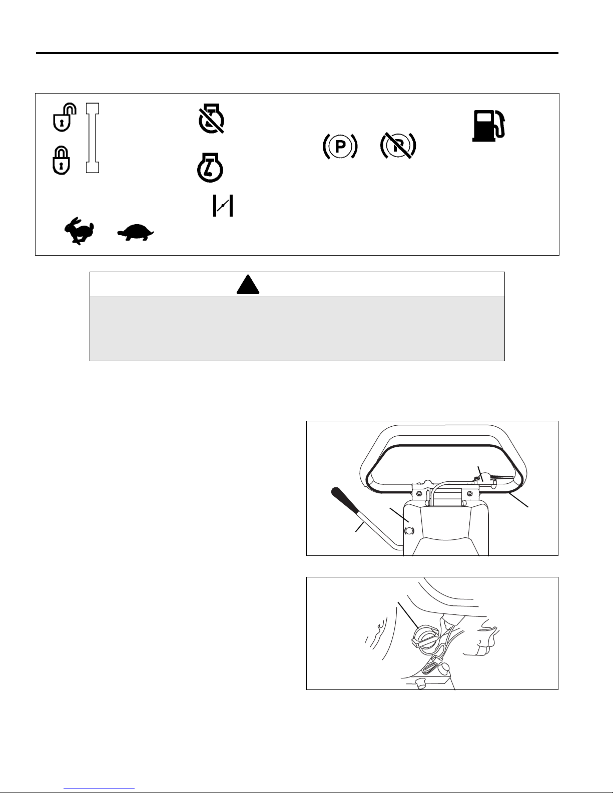
5 CONTROLS
Odklep MNPU
Zaklep MNPU
Potegnjena Izklopljena
Parkirna zavora
Gorivo
Bencin
Loputa
Motor je izklopljen
Motor je vklopljen
Visoka Nizka
Hitrost
!
N
D
P
C
B
A
J
OFF
ON
D
5 CONTROLS
5.1 IKONE_____________ __ ___ ________________ ________________ _________________
OPOZORILO
Naprave ne uporabljaj te, če niste p rebrali p riročnik a o varn osti in up ravlja nju ter pri ročnika
o delih in vzdrževanju ter priročnika o motorju, in znate varno upravljati z vsemi vodili.
Seznanite se z vsemi zgoraj prikazanimi ikonami in kaj predstavljajo. Preden začnete
uporabljati napravo, si zapomnite, kje se nahajajo posamezna vodila in njihov namen.
5.2 KRMILA _________________________________________________________________
A. Parkirna zavora – Uporabite jo, kadar kosilnic a ni v
uporabi ali kot pomožno zavoro pri transportu.
B. Drsno stikalo – N adzoruje hitrost motorja, kad ar je
vključen NPU. Potisnite drsnik na strani (+), da
hitrost motorja povečate, ali na strani (-), kadar
želite hitrost zmanjšati.
C. Varovalno stikalo NPU – Vklop varovalke poveča
hitrost motorja, kar vključi sklopko. Če stikalo
popustite, se motor vrne v prosti tek. Ob zagonu
motorja mora biti stikalo izklopl jen o.
D. Stikalo motorja – Stikalo motorja od klepa oziroma
zaklepa zagonski mehanizem. Stikalo mora biti v
položaju ON, da lahko zaženemo motor. Če to
stikalo obrnemo v položaj OF F, se motor ustavi.
OFF
Slika 5A
10
ON
Slika 5B
Page 39
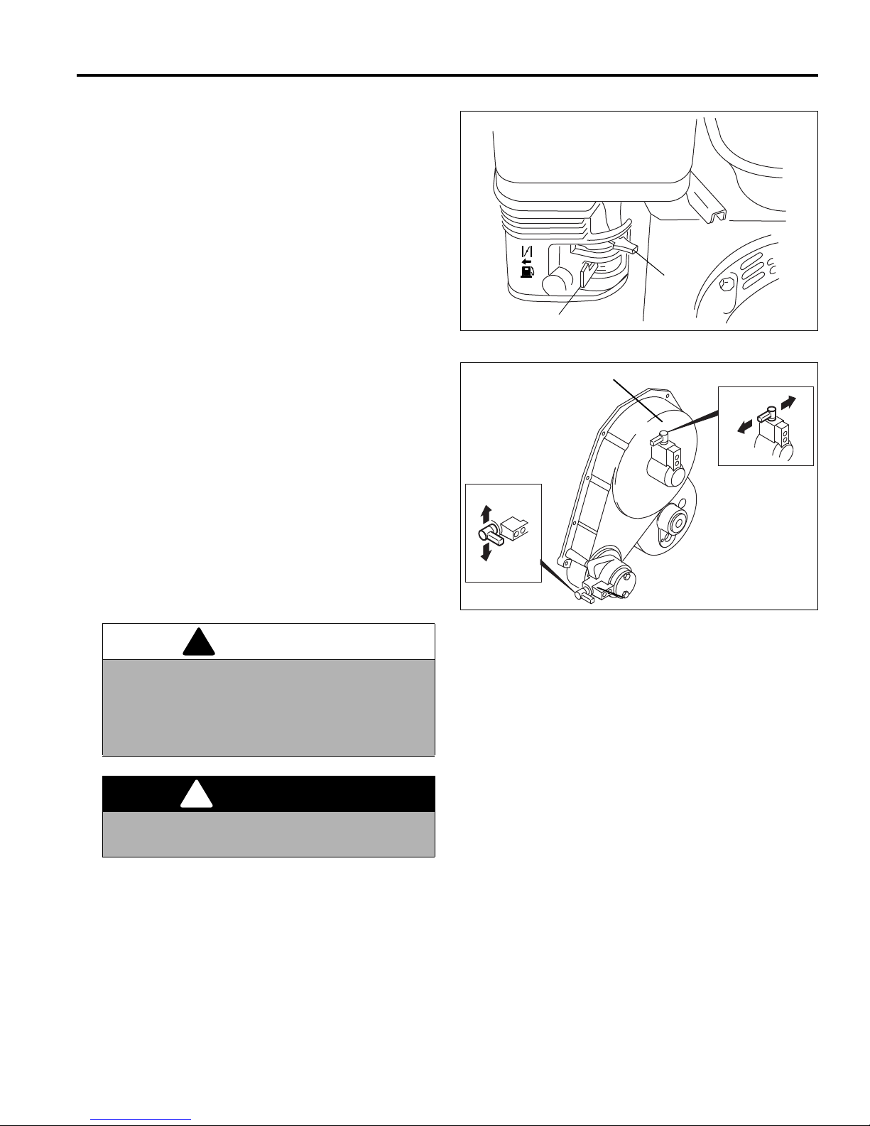
E. Regulator dušilke – Regulator skrbi za odpiranje in
!
!
ON
OFF
E
F
G
H
G
1
G
2
H
1
H
2
zapiranje dušilnega ventila v uplinjaču. Položaj
CLOSED pomeni bogato me šanico goriva, pri merno
za zagon hladnega motorja. Položaj OPEN
zagotavlja mešanico goriva, primetno za delo po
zagonu in za ponoven zagon ogretega motorja.
F. Ventil za dovod goriva – Ventil za dovod goriva
odpira oziroma zapira povezavo med posodo za
gorivo in uplinjačem. Ta ventil se mora nahajati v
položaju ON, kadar je motor vključen. Kadar je
motor ugasnjen, pustite ventil za dovod griva v
položaju OFF, da preprečite morebitno zalitje
uplinjača in zmanjšate možnost iztekanja goriva.
CONTROLS 5
Slika 5C
Opomba:
prilagoditve, premaknite ventil za dovod goriva v
položaj OFF da preprečite iztekanje goriva v pokrov
motorne gredi.
G. Ročica pogonske sklopke – Potisnite ročico naprej
(G
2
se prosto vrti. Po vlecite ročico nazaj (G
vključite.
H. Ročica pogonske sklopke – Potisnite ročico naprej
(G
2
se prosto vrti. Po vlecite ročico nazaj (G
vključite
Preden kosilnico nagnete nazaj za
), da izključite tračni pogon in pustite bobnu, da
), da pogon
1
), da izključite tračni pogon in pustite bobnu, da
), da pogon
1
OPOZORILO
Da bi preprečili telesne poškodbe in materialno
škodo, nikoli ne vključite sklopke tračnega
pogona in sklopke pogonskega mehanizma
vretena kadar motor deluje oziroma kadar je
vključeno varnostno stikalo NPU.
Slika 5D
NEVARNOST
Da preprečite težje ur eznine, rok o ziroma nog n e
približujte rezilom.
J. E-Stop – Uporablja se za ustavljanje motorja.
Potisnite stikalo navzdol, da onemogočite zagon
motorja. Povlecite stikalo navzgor za normalno
delovanje.
11
Page 40

6 OPERATION
!
!
6 OPERATION
6.1 VSAKODNEVNI PR EGLED ________________________ __ _________________ __ _____
komponente. Prepričajte se, da ojle oziroma gorivo
CAUTION
Vsakodnevni pregled naj se izvaja le, ko je motor izkl-
jučen in so tekočine hladne. Izključite vse pogone, pote-
gnite ročno zavoro, ustavite motor in izključite vžigalno
svečko.
ne iztekata.
2. Preverite zalogo goriva in gl adino olja v menjalni ku.
Vse posode s tekočinami naj bodo polne.
3. Poskrbite, da je na kosilnici nastavljena ustrezna
višina košnje.
1. Preglejte celotno napravo. iščite znake obrabe, slabo
pritrjene dele in poškodovane oziroma manjkajoče
4. Poskrbite, da je kosilnica us trezno pod mazana in da
so pnevmatike napolnjene do predpisanega pritiska.
5. Preizkusite sistem N.P.U.
6.2 NADZOR PRISOTONOSTI UPRAVLJALCA (N.P.U.) ______________________________
1. Sisitem N.P.U. je namenjen zaščiti upravljalca in
drugih ljudi pred po škodbami. Sistem u stavi vreteno
in pogonski meh anizem takoj, ko upravlj alec izpusti
stikalo N.P.U. naprava je še dodatno opremljena s
stikalom (E-Stop), ki ustavi motor iz položaja
operaterja.
OPOZORILO
Ne uporabljajte naprave, če je mehani zem N.P. U.
izključena ali okvarjen.
2. Za preizkus sistema:
a. Postavite kosilnico na stojalo.
b. Izključite sklopko vretena (E).
3. Zaženite motor.
a. Pomaknite stikalo NPU v levo, da zaženete meh-
anizem NPU.
b. Hitrost motorja se bo povečala, vključil se bo
pogonski mehanizem in kolesa se bodo začela
obračati.
c. Izpustite stikalo NPU. Mehanizem se mora
izključiti, motor se vrne v prosti tek in pogonski
mehanizem se mora ustaviti.
d. Potisnite stikalo E-St op navzdol. Motor se mora
nemudoma zaustaviti.
4. Če se pogonski mehanizem zažene preden
premaknete stikalo NPU, oziroma če se pogonski
mehanizem ne ustavi potem ko ste stikalo NPU
izpustili, nemudoma ustavite motor in pošljite
napravo v popravilo.
12
Page 41
OPERATION 6
!
!
!
6.3 DELOVNI POSTOPKI _______________________________________________________
POZOR
Da ne bi prišlo do poškodb, vedno nosite zaščitna očala, usnjene delovne čevlje oziroma škornje, klobuk in zaščito
za ušesa. Dolgi lasje, ohlapna oblačila in nakit se lahko zapletejo v gibljive dele.
1. Pod nobenim pogojem naj upravljalec ne poganja
motorja, kadar sto ji pred vretenom, oziroma se tam
nahajajo drugi ljudje.
2. Ne zaganjajte motorja v zaprtih prostorih.
3. Rok in nog ne približujte gib ljivim delom in rezilom.
Če je le mogoče, ne spreminjajte nastavitev, kadar
motor deluje.
4. Ne uporabljajte kosilnice oziroma priključkov, če so
deli slabo pritrjeni, poš kodovani ali manjkajo. Kadar
je to mogoče, kosite, ko je trava suha.
5. Najprej pokosite preizkusno področje, da se
temeljito seznanite z delovanjem in upravljanjem
naprave.
Opomba:
spodnjega noža, nikoli ne vključite vretena, če ne
režete trave. Med vretenom in spodnjim nožem se v
takšnem primeru razvije preveliko trenje in vročina.
6. Preglejte področje, da določite najboljši in
najvarnejši drelovni načrt. Upoštevejte višino trave,
tip retena in stanje površine. Vsak izmed teh
pogojev zahteva določene prilagoditve in varnostne
ukrepe. Uoprabljajt e le dodatke in priključke, ki jih je
odobrilo podjetje Jacobsen.
Da bi preprečili poškodbe vretena in
10. Izključite sklopko vretena, kadar prečkate poti ali
ceste. Pazite na promet.
11. Kadar zadanete ob oviro oziroma se naprava začne
nenormalno tresti, nemudoma ustavite in preglejte
opremo. Pred nadalje vanjem dela opravite potrebn a
popravila.
OPOZORILO
Pred čiščenjem, prilagajanjem ali servisom vedno
izključite vse pogone, potegnite ročno zavoro,
ustavite motor in odstranite svečko za vžig, da
preprečite poškodbe
12. Na pobočjih upočasnite in bodite še posebej
previdni. Bodite pazljivi pri delu v bližini previsov.
13. Poglejte nazaj in navzdol, preden zapeljete
vzvratno. prepričajte se, da je pot za vami prosta.
Bodite previdni, ko se približujete slepim kotom,
grmovju, drevesom in drugim objektom, ko lahko
zakrivajo pogled.
14. Rezil nikoli ne čistite z rokami. uporabite kr tačo, da
izrezil odstranite odrezke trave. Rezila so zelo ostra
in lahko povzročijo hude poškodbe.
7. Bodite pozorni na smer iznosa mate riala iz kosilnice
in ga nikoli ne usmerjajte proti drugim ljudem. Med
delom naj se v bližini kosilnice ne zadržujejo drugi
ljudje. Lastnik/upravljalec je odgovoren za telesne
poškodbe in materialno škodo, povzročeno
mimoidočim.
POZOR
Preden začnete s košnjo, poberite vovire kot na
primer kamenje, igrače in žice, ji jih naprava lahko
izvrže. Na novo področje vstopajte previdno. Vedno
delajte s hitrostjo, ki vam omogoča popoln nadzor nad
kosilnico.
8. Bodite posebej previdni, k o kosite v bližini peš čenih
področij (cest, parikirišč, poti, ipd.). Kamenje, ki ga
izvrže kosilnica, lahko poškoduje mimoidoče in/ali
njihovo opremo.
9. Kadar ne kosite, izključite sklopko vretena, da
ustavite rezila.
13
Page 42
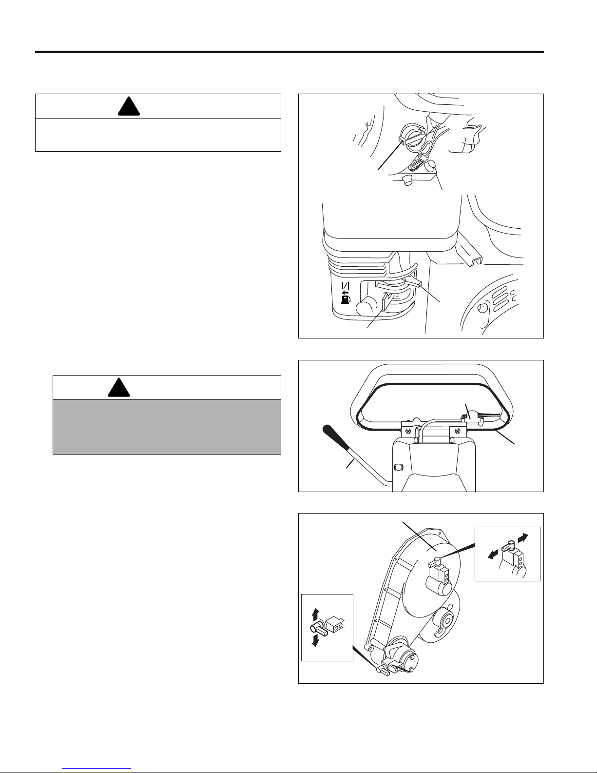
6 OPERATION
!
!
OFF
ON
OFF
ON
D
ON
OFF
E
F
N
D
P
C
B
A
G
H
G
1
G
2
H
1
H
2
6.4 VKLOP/IZKLOP MOTORJA__________________________________________________
POZOR
Motor vedno zaženite, ko je kosilnica na ravni
površini. Med zagonom nog ne približujte rezilom.
Zagon
1. Preverite nivo olja in zalogo goriva, nato odprite
ventil za gorivo (F).
2. Premaknite krmilo dušilke (E) v položaj “ZAPRTO” .
3. Premaknite stikalo motorja (D) v položaj “ON”.
4. Poskrbite, da je stikalo N.P.U (C) izključeno, ročna
zavora (A) pa vklj učena.
5. Ročici sklopke vretena (G) in (H) pomaknite v
ustrezen položaj.
Košnja - Vključite sklopko pogona (G
).
(H
1
Vožnja - Vključite sklopko pogona (G
sklopko vrtena (H
).
2
) in vretena
1
) in izključite
1
OPOZORILO
Da preprečite telesne poškodbe ali materialno
škodo, nikoli ne vklapljate sklopke pogona ali
vretena, kadar motor teče oziroma je vlopljeno
stikalo N.P.U.
6. Zaženite motor. ne pustite, da žica “odskoči” nazaj v
zaganjač. Kosilnice med zagonom ne nagibajte
nazaj .
7. Ko se motor zažene, poma knite krmilo dušilk e (F) v
položaj “ODPRTO”. Dokler je motor še hladen, je
občasno potrebno pripreti dušilko.
8. Pustite, da se motor počasi ogreje.
Ustavljanje
1. Ko ustavljate motor, sprostite stikalo N.P.U. (C), in
pomaknite stikalo (D) v p oložaj “OFF”. Zaprite ventil
za dotok goriva (F).
2. Potegnite ročno zavoro (A).
Slika 6A
Slika 6B
14
Slika 6C
Page 43
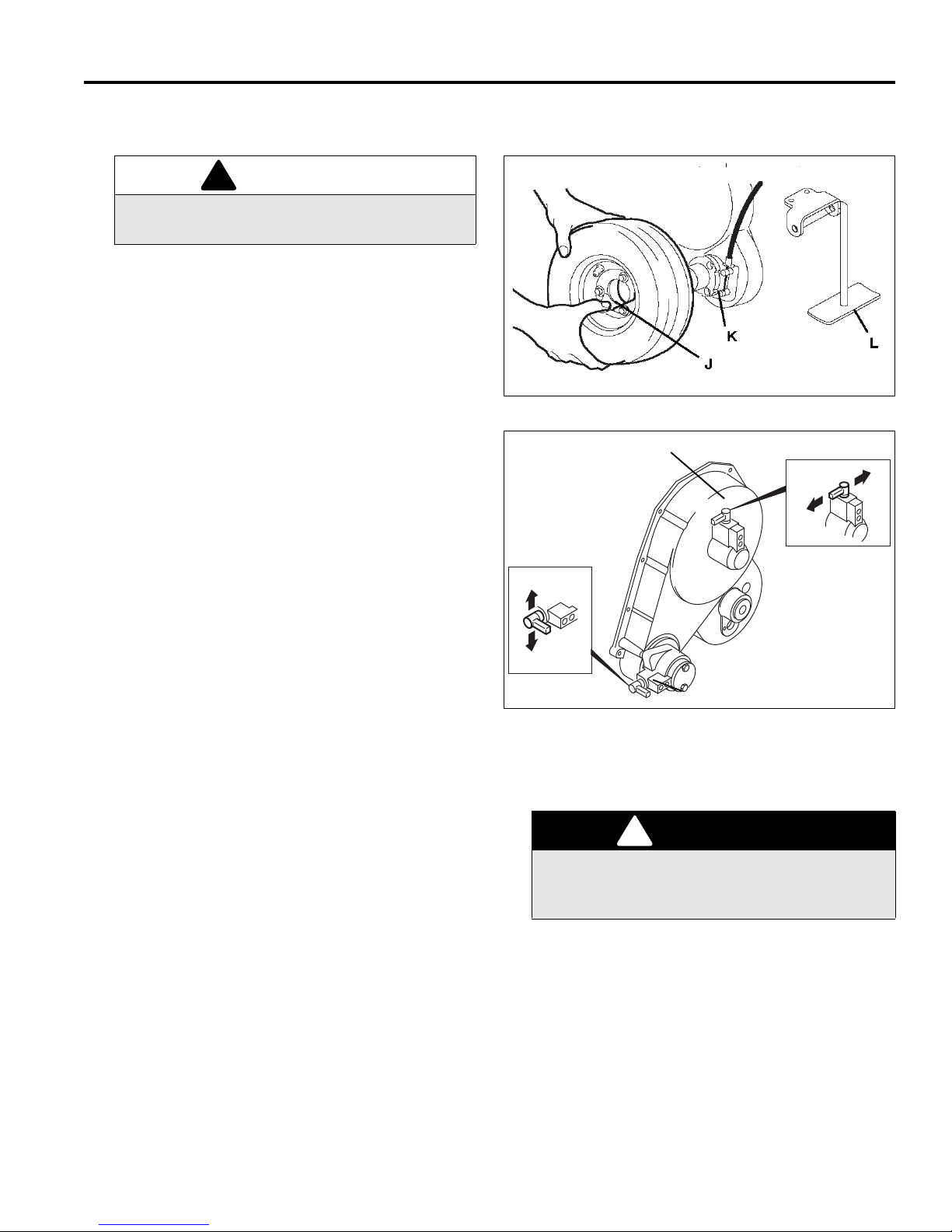
OPERATION 6
!
G
H
G
1
G
2
H
1
H
2
!
6.5 TRANSPORTNA KOLESA (DODATNA OPREMA) ________________________________
OPOZORILO
Vedno ustavite motor in izključite pogonske
ročice preden nameščate ali odstranjujet e kol esa.
1. Potisnite in postavite stojalo na tla, nato povlecite
ročaj kosilnice nazaj, dokler kosilnica ne počiva na
stojalu (L).
2. Kadar odstranjujete transportna kolesa, potisnite
spojko stran od pesta (K), nato odstran ite ko lo.
3. Kadar nameščate kolesa, pritisnite spojko na pesto
(K) in vrtite kolo nazaj, dokler se vijaki na zadnjem
delu ne poravnajo z luknjami v pestu (J). Potisnite
kolo in spustite spojko.
Slika 6D
4. Vedno izključite sklopko vretena (H
sklopko pogona (G
za več kot nekaj čevljev.
5. Potisnite kosilnico naprej iz stojala, zaženite motor
in vključite stikalo sistema N.P.U.
6. Kadar kosilnico prevažate z drugim vozilom,
potegnite ročno zavoro, ustavite motor in zaprite
ventil za dotok goriva.
7. Priporočen pritisk v pnevmatika h: 6 do 8 psi (41 do
55 kPa).
), preden kosilnico premaknete
1
) in vključite
2
Slika 6E
6.6 LOVILEC ZA TRAVO _______________________________________________________
1. Ko je košara do dveh tretjin (2/3) pol na trave, odpel-
jite kosilnico iz zelenice.
2. Ustavite na ravni površini, ugasnite motor in
izključite vse pogone.
3. Odstranite posodo za travo in jo izpraznite.
Da bi prepeprečili hude poško dbe , v edno ustav it e
motor in izključite vse pogone, preden praznite
posodo za travo.
NEVARNOST
6.7 UTEŽI____________________________________________________________________
1. Kosilnica je namenjena upor abi z dvigovalcem trav e
2. Kadar uporabljate sprednji valj, lahko odstranite
Jacobsen Turf Groomer®. Uteži, ki se naha jajo nad
odbojnikom za travo, se ob uporabi dvigovalnika
trave odstranijo.
uteži, ki kompenzirajo mehke zelenice in druge
pogoje pri košnji.
e. Ko s kosinico prečkate rob zelenice, spustite
glavo kosilnice in nadaljujte po zelenici v ravni
črti. Med košnjo držite za ročaj tako, da se
ogrodje ročaja ne bo dotikalo zaščit ročaja. Stik z
zaščitami na zgornji ozi roma s podnj i strani lahk o
povzroči neenakomerno košenje.
15
Page 44
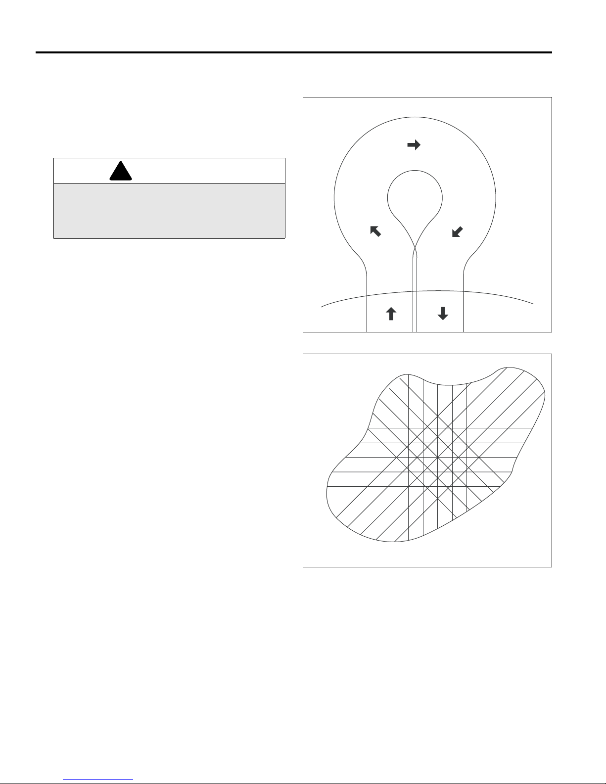
6 OPERATION
!
1
2
3
4
5
6.8 KOŠNJA _________________________________________________________________
1. Ustavite motor. Postavite kosilnico na stojalo in
odstranite transportna kolesa .
2. Vključite sklopko vretena (H
potisnite kosilnico nap re j iz sto jala. Za že nit e mo tor.
) in pogona (G1).
1
OPOZORILO
Da bi preprečili telesne poškodbe ali materialno
škodo, nikoli ne vključite sklopke vretena ali
pogona kadar motor deluje ali kadar je vključen
sistem N.P.U.
3. Postavite kosilnico poleg zunanjega roba zelenice.
a. Prilagodite hitrost motorja (B) tako, da bo hoja
varna in udobna.
b. Potisnite ročico navzdol, da dvignete glavo
kosilnice nad travo in vključite sistem N.P.U. (C).
c. Ko s kosilnico prečkate rob zelenice, spustite
glavo kosilnice na travo in prečkajte zelenico v
ravni črti.
d. Ko dosežete nasprotno stra n zelenice, potisnit e
ročico navzdol, da dvignete kosilnico, ne da bi
izključili N.P.U., in zapustite zelenico, da bi
obrnili. Lahko pa tudi izpustite stikalo N.P.U. in
zasukate kosilnico.
Slika 6F
Second
Mowing
e. Obrat v desno začnite s premikanjem kosilnice
rahlo v levo (2). Ko ste kosilnico premaknili
približno 1/2 š irine v levo, (3 in 4), jo z desno
roko hitro zasukaj te v desno. Ta način omogoča
hitro obračanje v malo korakih. [Slika 6F]
Opomba:
spodnjega noža, nikoli ne vključite vretena, če ne
režete trave. Med vretenom in spodnjim nožem se v
takšnem primeru razvije preveliko trenje in vročina.
4. Da bi bila košnja kar najbolj enakomerna in
temeljita, naj se zank e prekrivajo za 1 do 2 in., (25
do 50 mm), nato pa še enkrat ali večkrat obhodite
rob zelenice, da popravite neravne robove in ločite
površino za patanje od obrobe.
5. Za bolj enakomerno igralno površino in lepši izgled,
pri vsaki košnji zelenice spremenite vzorec. Vzorci,
ki jih kaže Slika 6G, so le predlogi. Upravljalec ali
nadzornik igr išča lahko izdelata vzorce, ki ustrezaj o
zelenici.
6. Bodite previdni na pobočjih in previsih.
Da bi preprečili poškodbe vretena in
First
Mowing
Fourth
Mowing
Third
Mowing
Slika 6G
16
Page 45

OPERATION 6
!
6.9 DNEVNO VZDRŽEVANJE____________________________________________________
1. Parkirajte kosilnico na ravni, horizontalni površini.
Potegnite ročno zavoro in ustavite motor.
2. Naoljite in podmažite vsa mesta, če je to potrebno.
3. Da ne pride do požara, kosilnico po vsaki uporabi
operite.
a. Napravo perite le s svežo vodo.
Opomba:
pospešuje razvoj rje in korozije kovinskih delov. Tako
se naprava prehitro obrabi in poškoduje. Tovrstne
okvare niso pokrite z garancijo.
b. Ne uporabljajte razpršilcev pod pritiskom.
c. Ne pršite vode na hladilne plavuti ali v dovod
Opomba:
motorja. Za čiščenje motorja uporabljajte stisnjen zrak.
4. Na koncu vsakega delovnega dne napolnite
rezervoar z gori vom. Ne polnite preko ramena ustja
za dotok goriva. Kadar naprave ne uporabljate,
zaprite ventil za gorivo.
Uporabljajte čist, svež, 86-oktanski neosvinčen
bencin.
Uporaba slane vode ali raztopin dokazano
zraka.
Ne perite vročega oziroma delujočega
pokrovček in dolijte olje po potrebi. Ne polnite do
vrha.
Z gorivom ravnajte previdno - je zelo vnetljivo.
Uporabljajte odobreno posodo za gorivo, izliv se mora
prilgati vratu rezervoarja. Izogibajte se uporabi lijev in
ročk za polnjenje rezervoarja.
OPOZORILO
Nikoli ne odstranjujte pokrovčka rezervoarja oziroma
dodajajte goriva, kadar motor deluje oziroma je vroč.
Dadar delate z gori vom, ne kadite. Ne polnite oz ir om a
praznite rzervoarja za gorivo v zaprtih prostorih.
Ne polivajte goriva in nemudoma počistite polito
gorivo.
Ne hranite oziroma uporabljajte goriva v bližini
odprtega ognja ali naprav, ki povzročajo iskre, ki lahko
vžgejo gorivo ali hlape.
Pokrovček rezervoarja vedno čvrsto pritidite nazaj.
5. Gorivo hranite v skladu z lokalno, državno oziroma
zvezno zakonodajo in nasveti dobavitelja.
6. Na začetku vsakega dne, preden zaženete motor,
preverite gladino olja. Če je gladina nizka, od stranit e
17
Page 46
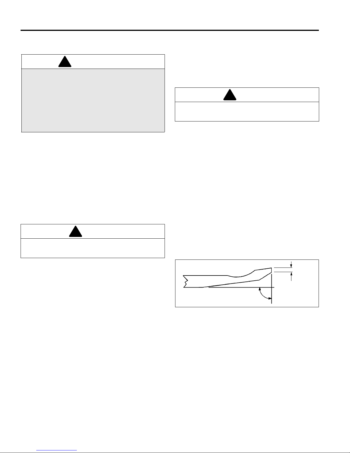
7 ADJUSTMENTS
!
!
!
¬
¬
1/32‚
(0.8 mm)
7 ADJUSTMENTS
7.1 SPLOŠNO_____ ___ __ __ _________________ ________________ ________________ ___
2. Obrabljenih oziroma okvarjenih komponent ne
OPOZORILO
Preden prilagajate, čistite ali popravljate napravo,
vedno izključite vse pogone, potegnite ročno zavoro
in ustavite motor. S tem boste preprečili resne
poškodbe.
Kadar koli izvajate vzdrževalna dela, ki niso
povezana s nastavitvami uplinjača, odstranite
vžigalno kapo in jo ne pustite v bližini svečke, da
preprečite neželen vžig in telesne poškodbe.
1. Prilagoditve in vzdrževanje naj vedno izvaja kvalificirano tehnično osebje. Če pravilnih nastavitev ni mogoče doseči, se obrnite na pooblaščene prodajalce
podjetja Jacobse n.
7.2 VRETENO IN SPODNJI NOŽ_________________________________________________
(Preizkus pred nastavitvami)
1. Prepričajte se, da nosilci na vretenu niso razrahljani v
nobeni smeri. Če opazite nenormalno gibanje
vretena – navzgor in navzdol oziroma vstran – po
potrebi prilagodite oziroma zamenjajte sestavne
dele.
POZOR
Da bi preprečili telesne poškodbe in poškodbe na
rezilih, z vretenom ravnajte izredno previdno.
popravljajte, ampak jih zamenjajte.
3. Dolgi lasje, nakit ozirom a ohlapna oblačila se lahko
zapletejo v gibljive dele.
POZOR
Bodite previdni, da se vaše roke ali prsti ne ujamejo
med gibljive in fiksne dele naprave.
4. Ne spreminjajte glavnih nastavitev oziroma ne
preobremenite motorja.
5. Kljuka za dviganje se nahaja med motorjem in
mehanizmom sklopke, tako da lahko kosilnico na
lahek način dvignemo na delovno površino.
5. Vreteno mora biti vzporedno s spodnjim nožem.
Nepravilno nameščeno vreteno bo prehitro izgubilo
svoje ostre robove, lahko pa pride tudi do resnih
poškodb vretena in spodnjega noža.
6. Na nastavitve bodo vplivale tudi lastnosti trave.
a. Suha in redka trava zahteva širši razmik, da
preprečimo pregrevanje vretena in spodnjega
noža ter posledično njune poškodbe.
b. Trava visoke kvalitet e z visoko vsebnostj o vlage
zahteva manjši razmik (blizu ničli).
2. Prepričajte se, da imajo rezila in spodnj i nož ostre in
ravne robove brez udarnin.
a. Robovi rezil in spodnj ega noža morajo biti ostr i,
brez odrgnin in ne smejo kazati znakov okroglin.
b. Spodnji nož in hrbet spo dnjega noža mora ta biti
čvrsto pritirjena. Spodnji nož mora biti oster in
raven.
c. Ploska površina dolžine najmanj 1/32 in (0.8
mm) mora biti vedno prisotna na prednji strani
spodnjega noža. Za brušenje spodnjega noža
uporabite standardno plosko pilo.
3. Kadar obrabe in poškodbe vretena ali spodnjega
noža ni več mogoče popraviti z prekrivanjem, jih je
potrebno ponovno nabrusiti.
4. Pravilna nastavitev vretena in spodnjega noža je
zelo pomembna. Vzdolž celotne dolžine vretena in
spodnjega noža je potrebno vzdrževati razmak v
velikosti od 0,001’’ do 0,003’’ (0,025 mm do 0,076
mm).
18
Slika 7A
Page 47
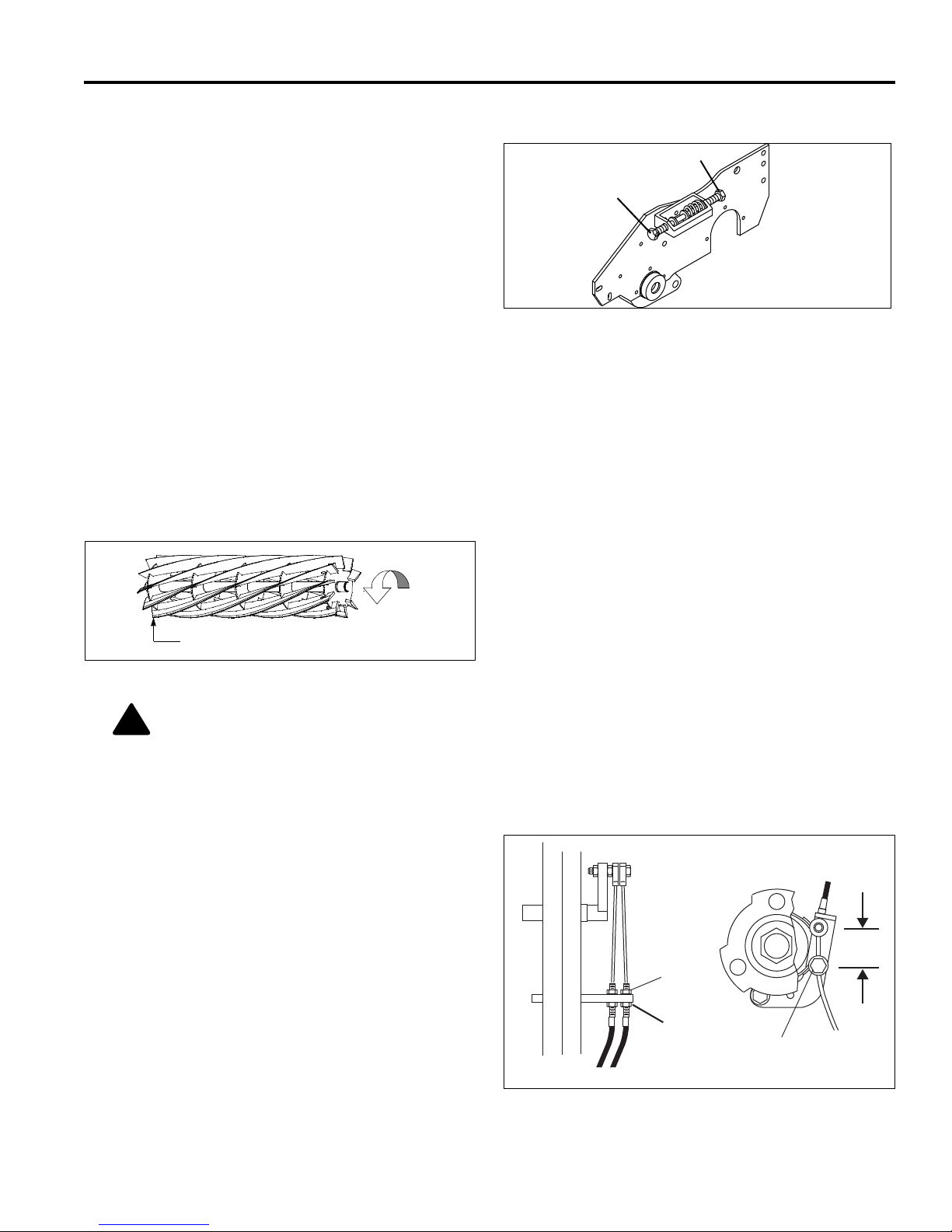
ADJUSTMENTS 7
A
B
Smer vrtenja
Vodilni rob
!
7.3 REGULATOR SPODNJEGA NOŽA ____________________________________________
1. Regulator (A) se uporablja za povečevanje ali
zmanjševanje vzmetn e sile na spod njem nožu. Regulator uporabljamo za pomikanje spodnjega noža
bližje vretenu ali stran od nje.
2. Ko se vzmet do konca sesede zaradi preveč
regulacije, spodnje ga noža ni ve č mogoče prem ikati.
Pred spreminjanjem nastavitev regulatorja (B)
umaknite regulator (A).
3. Za široko uporabo vzmet skrčite do dolži ne 1’’ i n (25
mm).
Slika 7B
7.4 SPODNJI NOŽ _____ ___ ________________ ________________ _________________ ___
1. Preberite razdelek 7.2 preden spreminjate nastav-
itve.
2. Spremembe začnite uveljavljati na vodilnem robu
vretena in nadal jujte s po možnim. Vodilni rob je tisti,
ki prvi prečka spodnji nož ob normalnem vrtenju
vretena.
Slika 7C
POZOR: Z vretenom bodite skrajno
previdni, da preprečite telesne poškodbe
in materialno škodo.
3. Regulator (B) obrnite v smeri urnega kazalca, da
spodnji nož približate vretenu z rezili oziroma
zavrtite regulator v naspr otni smeri urnega kazalca,
kadar želite spodnji nož pomakniti stran od vretena.
a. Med vreteno in spodnji nož potisnite merilno
napravo ali kontrolno paličico velikosti 0,001’’0,003’’ in (0,25-0,75 mm). Ne premikajte vretena.
b. Na enak način prilagodite tudi pomožni konec,
potem pa ponovno preverite nastavitve
vodilnega roba.
c. Ko sta spodnji nož in vreteno pravilno
nameščena, se bo vreteno vrtela prosto in bo
razrezala časopisni list vzdolž celotne dolžine
vretena, kadar papir vstop a v vreteno pod koto m
90° glede na spodnji nož.
7.5 ZAVORA _________________________________________________________________
Pravilno uravnana za vora zahteva vlečno silo 10 lb. na
vrhu zavorn e ročice, da se vključi. Kad ar je sproščena,
mora biti razdalja med središčema 1,50’’ (38 mm).
1. Manjše prilagoditve se izvajajo na ročici. Za
regulacijo zavornega kabla sprostite vijak (H), nato
obrnite vijak (J).
2. Če nastavitev ni mogoče spreminjati na ročici,
odstranite kolo in p rilagoditve opravite na z avornem
jermenu.
3. Popustite vijak (K) in povlecite kabel, da dosežete
željeno napetost zavornega jermena. Privijte vijak
(K) in ponovno prilagodite (H) in (J).
1.50”
(38 mm)
H
J
K
Brake Band
Slika 7D
19
Page 48
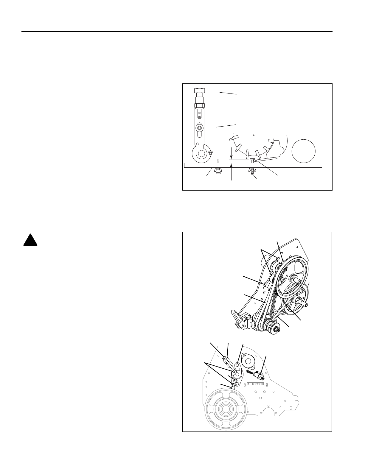
7 ADJUSTMENTS
L
M
N
O
P
Q
POZOR: Da preprečite trajno poškodbo
jermena, ga ne zvijajte , prepogibajte, kriv ite, ali
premočno pričvrstite.
!
A
F
B
C
D
E
K
L
M
H
G
N
F
7.6 VIŠINA KOŠNJE ___________________________________________________________
Opomba: Prepričajte se, da je spodnji nož pravilno
nastavljen preden določate višino reza (glej razdelek 7.4).
1. Potisnite stojalo navzdo l in prevrnite kosilnico nazaj
na ročaj. Kosilnice ne pustite predolgo v nagnjenem
položaju, da preprečite iztekanje olja v izgorevalne
komore.
2. Popustite vijaka (M) na obeh straneh tako , da ročaj
(L) dv igne prednji del česalnik a za rušo. Oba konca
dvignite enako visoko.
3. Z merilnim vijakom (P) določite želeno višino reza
(O). Merite od merilnega roba (N) prot i spodnji strani
glave vijaka, nato pa privijte vijak s krilci, da
blokirate nastavitve.
4. Postavite merilno palico med prednji in pomožni
valj; blizu zunanjih robov valjov.
5. Potisnite glavo vijaka preko spodnjega noža (Q) in
prilagodite ročaj tako, da se valj rahlo dotakne
merilne palice.
6. Ponovite korake na nasprotni strani vretena in
pričvrstite vijake (M). Ponovno preverite in nastavit e
višino reza, če je to potrebno.
Slika 7E
7.7 NASTAVITEV JERMENOV___________________________________________________
.
1. Jermen (A) je se premika s pomočjo ko les a z utorom
in vzmeti. Prilagajanje ni potrebno.
2. Za prilagajanje jermenov (B) in (C), rahlo privijte
vijak velikosti 5/16-18×3-3-1/4’’ in šestkotno glavo
(K) skozi konzolo z 5/16-18 šestkotnimi maticami.
Pričvrstite vijak dimenzij 5/16-18×1’’ in šestkotno
glavo ter 5/16-18’’ šes tkotno matico na dno nosilne
objemko (G). Razrahljajte vijaka (E).
a. Postavite merilni rob spodn jega noža (H) na vrh
b. Privijajte vijak (K) do kler pa s (C) ne odv rne 9/6 4’’
c. Privijte mati ce (E) in odstranite vijak dimenzij 5/
Opomba:
zgornja matica lahko ostaneta na svojem mestu po
končanem prilagajnju, ne da bi ovirala delovanje.
3. Opremo (L in N) spravite na varno mesto za
prihodnje prilagoditve.
valja in pod vijak (L). Privijajte vijak (L) dokler
pas (B) ne odvrne 1/10’’ (2,5mm) z bremenom
12,2~15,2 lb (5,5 ~ 7,4 kg) na sredini.
(3,5mm) s tovorom 3,5~6,3 lb (1,59 ~ 2,86 kg) na
sredini.
16-18×1’’ (L) in spodnjo matico (N).
Vijak z dimenzijami 5/16-18×3-3-1/4’’ (K) in
Slika 7F
20
Page 49
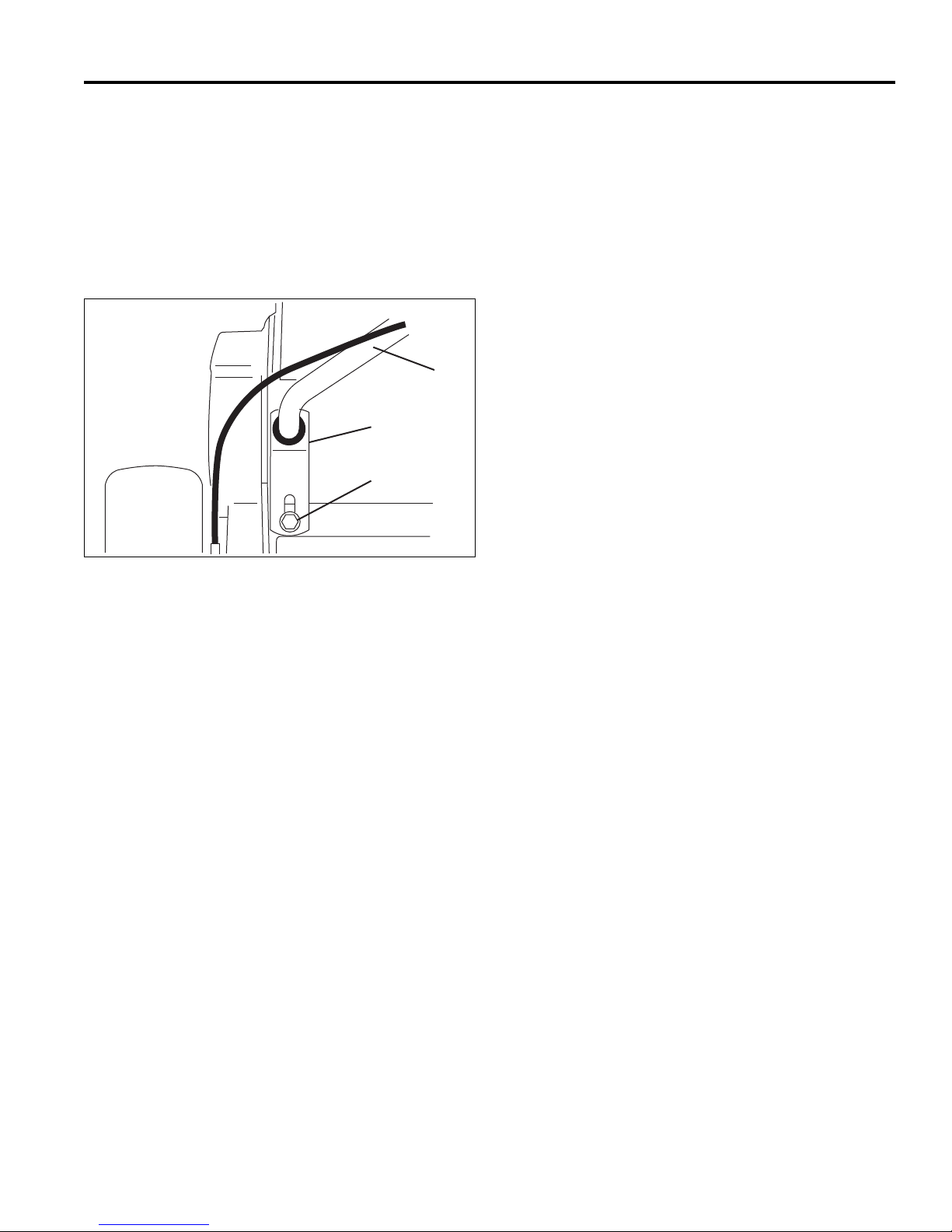
ADJUSTMENTS 7
Y
7.8 ROČAJ __________________________________________________________________
1. Za prilagoditev kota ročaja (Y), popustite vijak (W) na
obeh straneh kosilnice in postavite ročaj v želeni
položaj.
2. Potem ko ste prilagodili položaj ročaja, nastavite
objemko (X) tako, da bo ročaj rahlo počival na dnu
reže v objemki. Privijte vijak (W).
X
W
Slika 7G
21
Page 50
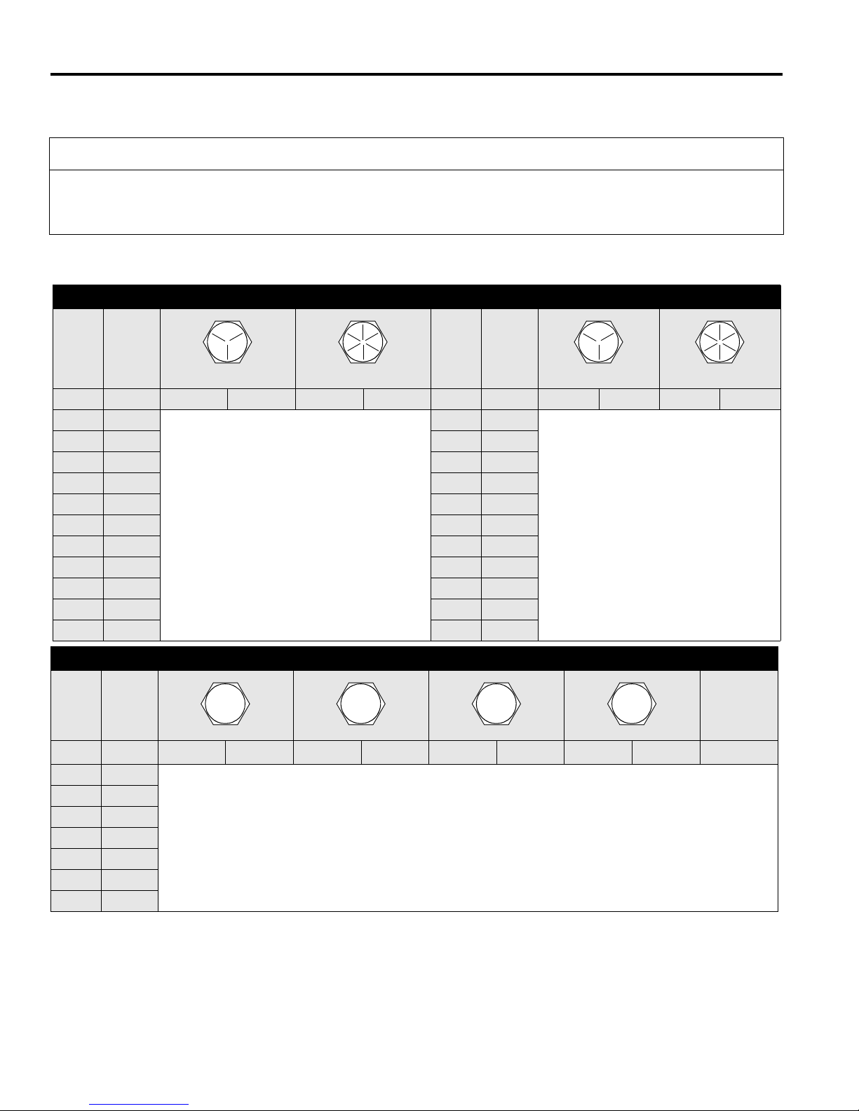
7 ADJUSTMENTS
4.6
8.8
10.9
12.9
7.9 SPECIFIKACIJE VIJAKOV __________________________________________________
POZOR
Vse vrednosti navedene v tej tabeli naj služijo zgolj za referenco. Tabele in vrednosti uporabljajte na lastno
odgovornost. Podjetje Jacobsen ne odgovarja za škodo, ki izvira iz uporabe teh vrednosti. pri uporabi katerekoli
vrednosti za vijake bodite vedno zelo previdni.
Podjetje Jacobsen kot standard uporablj a ploščate vijake stopnje 5, razen kjer ne navedeno dr ugače. Za privijanje
vijakov uporabljajte vrednosti, navedene za podmazane.
AMERIŠKI NACIONALNI STANDARDNI VIJAKI
MERE ENOTE STOPNJA 5 STOPNJA 8 MERE ENOTE STOPNJA 5 STOPNJA 8
Podmazan Suh Podmazan Suh Podmazan Suh Podmazan Suh
#6-32 in-lb (Nm) – 20 (2.3) – – 7/16-14 ft-lb (Nm) 37 (50.1) 50 (67.8) 53 (71.8) 70 (94.9)
#8-32 in-lb (Nm) – 24 (2.7) – 30 (3.4) 7/16-20 ft-lb (Nm) 42 (56.9) 55 (74.6) 59 (80.0) 78 (105)
#10-24 in-lb (Nm) – 35 (4.0) – 45 (5.1) 1/2-13 ft-lb (Nm) 57 (77.2) 75 (101) 80 (108) 107 (145)
#10-32 in-lb (Nm) – 40 (4.5) – 50 (5.7) 1/2-20 ft-lb (Nm) 64 (86.7) 85 (115) 90 (122) 120 (162)
#12-24 in-lb (Nm) – 50 (5.7) – 65 (7.3) 9/16-12 ft-lb (Nm) 82 (111) 109 (148) 115 (156) 154 (209)
1/4-20 in-lb (Nm) 75 (8.4) 100 (11.3) 107 (12.1) 143 (16.1) 9/16-18 ft-lb (Nm) 92 (124) 122 (165) 129 (174) 172 (233)
1/4-28 in-lb (Nm) 85 (9.6) 115 (13.0) 120 (13.5) 163 (18.4) 5/8-11 ft-lb (Nm) 113 (153) 151 (204) 159 (215) 211 (286)
5/16-18 in-lb (Nm) 157 (17.7) 210 (23.7) 220 (24.8) 305 (34.4) 5/8-18 ft-lb (Nm) 128 (173) 170 (230) 180 (244) 240 (325)
5/16-24 in-lb (Nm) 173 (19.5) 230 (26.0) 245 (27.6) 325 (36.7) 3/4-10 ft-lb (Nm) 200 (271) 266 (360) 282 (382) 376 (509)
3/8-16 ft-lb (Nm) 23 (31.1) 31 (42.0) 32 (43.3) 44 (59.6) 3/4-16 ft-lb (Nm) 223 (302) 298 404 315 (427) 420 (569)
3/8-24 ft-lb (Nm) 26 (35.2) 35 (47.4) 37 (50.1) 50 (67.8) 7/8-14 ft-lb (Nm) 355 (481) 473 (641) 500 (678) 668 (905)
METRI?NI VIJAKI
Manj
pomembni
vijaki za
MERE ENOTE
Podmazan Suh Podmazan Suh Podmazan Suh Podmazan Suh
M4 Nm (in-lb) – – – – – – 3.83 (34) 5.11 (45) 2.0 (18)
M5 Nm (in-lb) 1.80 (16) 2.40 (21) 4.63 (41) 6.18 (54) 6.63 (59) 8.84 (78) 7.75 (68) 10.3 (910 4.0 (35)
M6 Nm (in-lb) 3.05 (27) 4.07 (36) 7.87 (69) 10.5 (93) 11.3 (102) 15.0 (133) 13.2 (117) 17.6 (156) 6.8 (60)
M8 Nm (in-lb) 7.41 (65) 9.98 (88) 19.1 (69) 25.5 (226) 27.3 (241) 36.5 (323) 32.0 (283) 42.6 (377) 17.0 (150)
M10 Nm (ft-lb) 14.7 (11) 19.6 (14) 37.8 (29) 50.5 (37) 54.1 (40) 72.2 (53) 63.3 (46) 84.4 (62) 33.9 (25)
M12 Nm (ft-lb) 25.6 (19) 34.1 (25) 66.0 (48) 88.0 (65) 94.5 (70) 125 (92) 110 (81) 147 (108) 61.0 (45)
M14 Nm (ft-lb) 40.8 (30) 54.3 (40) 105 (77) 140 (103) 150 (110) 200 (147) 175 (129) 234 (172) 94.9 (70)
aluminij
22
Page 51

MAINTENANCE 8
!
!
!
8 MAINTENANCE
8.1 SPLOŠNO ___________________ __ __ ___ ________________ ________________ ______
d. Vzdržujte ustrezen nivo gladine vseh tekočin.
OPOZORILO
Pred prilagajanjem, čiščenjem ali popravljanjem
naprave, vedno izklju čite vse pogone, potegnite ročno
zavoro in ustavite motor. S tem bos te preprečili hude
poškodbe.
Kadar koli izvajate vzdrževalna dela, ki niso povezana
s nastavitvami uplinjača, odstranite vžigalno kapo in jo
ne pustite v bližini svečke, d a preprečite neželen vžig
in telesne poškodbe.
e. Zaščitni deli naj bod o na svoje m mestu in čvrsto
pritirjeni.
f. Pnevmatike naj bodo ustrezno napolnjene.
3. Dolgi lasje, nakit in ohlapna oblačila se lahko
zapletejo med gibljive dele.
POZOR: Pazite, da se vaši prsti oziroma
roke ne ujamejo med gibljive in fiksne dele
stroja.
1. Prilagoditve in vzdrževanje naj vedno izvaja kvalificirano tehnično osebje. Če ustreznih nastavi t ev ni mogoče doseči, se obrnite na pooblaščene prodajalce
podjetja Jacobse n.
2. Redno pregledujte opremo. Določite urnik
vzdrževanja in vodite natančen dnevnik
a. Naprava naj bo čista.
b. Vsi gibljivi deli naj bodo ustrezno nastavljeni in
podmazani.
c. Pred uporabo zamenjajte obrabljene ali
poškodovane dele.
4. Za referenco pri razstavlajju ali sestavljanju
komponent uporabite ilustracije v katalogu delov.
5. Reciklirajte oziroma odlagajte vse nevarne m ateriale
(gorivo, maziva ipd.) v skladu z lo kalnimi, državnimi
ali zveznimi predpisi.
6. Ne spreminjajte vodilnih nastav itev in ne prekora čite
hitrosti motorja.
7. Kljuka za dviganje se nahaja med motorjem in
mehanizmom sklopke, tako da lahko kosilnico na
lahek način dvignemo na delovno površino.
8.2 MOTOR __________________________________________________________________
POMEMBNO: Poseben priročnik za motor, ki ga je
sestavil proizvajalec motorja, je priložen tej napravi.
Priročnik skrbno preberite, da se seznanite z
delovanjem in vzdrževanjem motorja. Dosledno
upoštevanje navodil proizajalca zagotavlja najdaljšo
življenjsko dobo motorja. Za naročilo nadomestnega
priročnika za motor se obrnite na proizvajalca.
3. Pustite, da se motor segreje na delovno
temperaturo, preden ga polno obremenite.
4. Zamenjejte motorno olje po prvih 20 urah delovanja.
5. Specifične intervale za vzdrževanje najdete v
razdelku 10.2 in v priročniku za motor.
Pravilen začetek dela z novim motorjem lahko močno
vpliva na delovanje motora in njegovo življenjsko dobo .
Opomba:
tavljenimi vodilnimi nastavitvami. Ne spremijajte
vodilnih nastavitev motorja ozirma ne prekoračite
hitrosti.
V začetnem obdobju upoštevajte naslednja priporočila:
1. Prvih 25 ur napravo uporabljajte zmerno in
zmanjšajte hitrost motorja.
2. Izogibajte se zagananju s polnim plinom in hitrim
pospeškom.
Kosilnica najbolje deluje in kosi z prenas-
23
Page 52
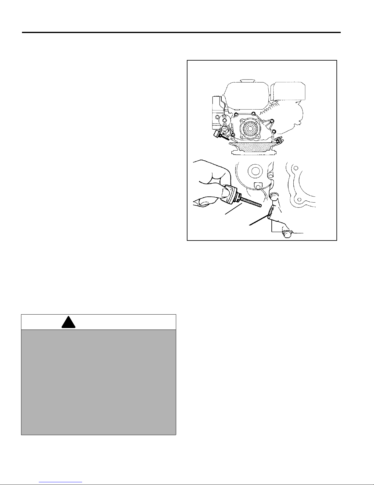
8 MAINTENANCE
Najv. gladina olja
Pokrov posode
!
8.3 MOTORNO OLJE____ __ ___ __ ________________ _________________ __ ____________
Na začetku vsakega dne, preden zaženete motor,
preverite gladino olja. Če je gladina nizka, odstranite
pokrovček in dolijte olje po potrebi.
Olje prvič zamenjajte po 20 urah dela, nato pa na vsak ih
100 delovnih ur.
Podrobjejše informacije o oskrbi motorja najdete v
priročniku za motor.
Po menjavi ali dol ivanju olja naj motor del uje v prostem
teku 30 sekund, pri čemer so vsi pogoni izključeni.
Ugasnite motor. počakajte 30 sekund in preverite gladino
olja. dodajte olje, da bo gladina segala do oznake
POLNO na merilcu.
Uporabljajte le motorna olja SAE 10W30 z API
clasifikacijo SG.SF/CC.CD
Slika 8A
8.4 GORIVO _________________________________________________________________
Z gorivom ravnajte previdno, ker je vnetljivo.
Uporabljajte odobreno posodo za gorivo, izliv se mora
prilgajati vratu r ezervoarja. Izogibajte se upo rabi lijev in
ročk za polnjenje rezervoarja.
OPOZORILO
Nikoli ne odstranjujte pokrovčka rezervoarja oziroma
dodajajte goriva, kadar motor deluje oziroma je vroč.
Kadar delate z gorivo m, ne kad ite. Ne pol nite oz irom a
praznite rezervoarja za gorivo v zaprtih prostorih.
Ne polivajte goriva in nemudoma počistite polito
gorivo.
Ne hranite oziroma uporabljajte goriva v bližini
odprtega ognja ali naprav, ki povzročajo iskre, ki lahko
vžgejo gorivo ali hlape.
Pokrovček rezervoarja za gorivo vedno čvrsto pritidite
na njegovo mesto.
• Ne polnite prekomerno oziroma ne dopustite, da se
rezervoar sprazni.
• Uporabljajte čist, svež, 86-oktanski neosvinčen
bencin.
• Pred uporabo obogatenega goriva (mešanice)
preberite priročnik za motor.
• Ne polnite prekomerno.
• Gorivo hr anite v skladu z lokal nimi, državnimi oziroma
zveznimi predpisi in nasveti dobavitelja.
24
Page 53
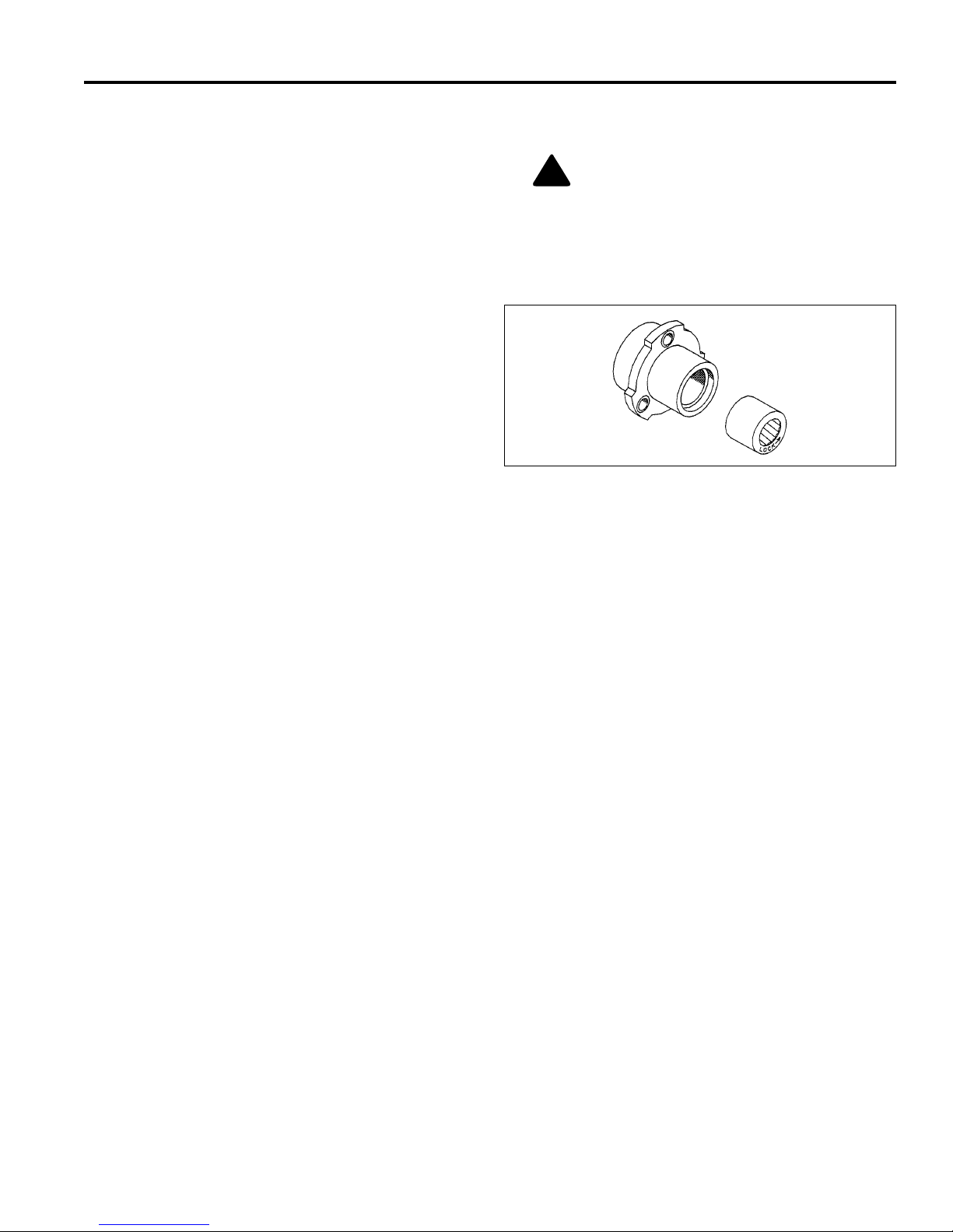
MAINTENANCE 8
!
8.5 KOLESA _________________________________________________________________
1. Da bo podaljšali njihovo življenjsko dobo, naj bodo
pnevmatike ustrezno napolnjene.
2. Uporabite natančen merilec pritisk a. 6 - 8 psi (41.3-
551. kPa)
POZOR: Če nimate ustreznega znanja,
orodja in izkušenj, NE skušajte namestiti
pnevmatike na obroč. Nepravilna
namestitev lahko pripelje do eksplozije, ki
lahko povzroči težke poškodbe .
8.6 NOSILCI KOLES___________________________________________________________
Nosilec koles ima na prednji strani vtisnjeno besedo
LOCK in puščico. Kad ar menjate nosilec, se pr epričajte,
da je nosilec pravilno u smerjen oziroma se v rti v pravo
smer .
Za desno kolo namestite nosilec tako, da bo beseda
“LOCK" s puščico na zunanji strani ohišja nosilca.
Za levo kolo namestite nosilec tako, da bo beseda
“LOCK" s puščico na notranji strani ohišja nosilca.
Slika 8B
8.7 BRUŠENJE IN OSTRENJE____________________________ ______________ _________
Preglejte spodnji nož in rezila za poškodbe. Glej
(Razdelek 7.2).
1. Ugotovite, ali bo brušenje oziroma ostrenje rezilu
vrnilo potrebno ostrino.
2. Za najvčjo učinkovitost uporabite brus za spodnji
nož za popravke, nato pa ponovno namestite in
uravnajte sposnji nož glede na vreteno, kot je
opisano v (Razdelek 7.2).
3. Odstranite pokrov gredi iz desne strani in namestite
3/8-24 zat ič in zaklep na konec gredi.
a. Z daljšim čopičem nanesite brusilno sredstvo
vzdolž celotnega vretena, (priporočljiva velikost
zrn je 180, Razdelek 2.6).
b. Nadaljujte z brušenjem in istočasno rahlo
prilagajate nasta vitve spodnjega noža, dokler ni
razmik med rezili in spodnjim nožem
enakomeren vdolž celotne dolžine rezil.
4. Pazljivo in temeljito odstranite vse brusilno sredstvo
iz vretena in spodnjega noža preden zavrtite
vreteno v smeri naprej.
25
Page 54

8 MAINTENANCE
!
8.8 SKLADIŠČENJE___________________________________________________________
Splošno
1. Temeljito operite kosilnico in jo podmažite.
2. Popravite in pobarvajte izpostavljene dele kovine.
3. Preglejte kosilnico in pričvrstite vse komponente,
obrabljene in poškodovane dele pa zamenjajte.
Spolirajte spodnji nož in vreteno.
4. Odmaknite spodnji nož od vretena in na rezila
vretena in spodnji nož nanesite sredstvo proti
rjavenju.
5. Kosilnica naj počiva na stojalu, da kolesa niso
obremenjena. Sprednji valj ali dvigovalnik za travo
naj počivata na leseni deski.
6. Kosilnica in vsa dodatna oprema naj bo shranjena
na suhem in čistem mestu in zaščitena pred
elementi. Nikoli ne hranite opreme s posodo za
gorivo v zgradbi, kjer hlapi lahko pridejo v stik z
iskrami ali odprtim ognjem.
7. Ne skladiščite v bližini vnetljivih odpadkov.
Motor
Po skladiščenju
1. Preverite oziroma očistite zračni filter in filter za
gorivo.
2. Preverite nivo olja v menjalniku.
3. Napolnite rezervoar s sv ežim go rivom. O dprite ventil
za gorivo.
4. Odstranite olje iz robov rezil. Ponovno nastavite
Vreteno in spodnji nož ter višino košnje.
5. Podstavite kosilnico tako, da je pogon ski boben nad
tlemi, in izključite sklopko vretena. Zaženite motor,
ki naj dela s polovično močjo. Pustite, da se dobro
ogreje in podmaže.
Opomba:
polovično močjo.
Pogonski boben se bo vrtel, če bo motor delal s
OPOZORILO
Ne pustite, da motor deluje brez ustreznega zračenja;
vdihanje izpušnih plinov je lahko smrtonosno.
1. Dokler je motor topel, odstranite zamašek odtoka, da
olje izteče iz menjalnika. Ponovno namestite
zamašek in nalijte novo olje. Zamašek pričvrstite do
22 ft. lb. (30 Nm).
2. Očistite zunanjost motorja. Pobarvajte iz postavljene
dele kovine ali jih zaščitite s sredstvom proti rji.
3. Da bi preprečili nabiranje ostankov in usedlin,
uporabljajte stabil izirano gorivo. Uporabljajte antioksidacijski dodate k k gorivu, ko t na primer STA-BIL®.
Preberite in upoštevajte navodila na embalaži.
4. Pustite, da motor deluje približno pet minut, da
oplemeniteno gorivo zak roži. Ustavite motor, zaprite
ventil za gorivo in pustite, da se motor ohladi.
Iztočite gorivo.
5. Odstranite svečko za vžig i n vlijte pr ibližn o eno u nčo
(28,35 g) olja SAE 30 v c ilindre. Počasi vrtite m otor,
da se olje porazdeli po stenah cilindra. ponovno
namestite svečko za vžig.
6. Potegnite vrv zaganjača, dok ler ne začutute odpo ra.
Vlecite še naprej, dokler se zareza na vitlu
zaganjača ne pora vna z luknjo na zag anjaču. Takrat
so vsi vhodni in izhodni ventili zaprti.
26
Page 55

TROUBLESHOOTING 9
9 TROUBLESHOOTING
9.1 SPLOŠNO ___________________ __ __ ___ ________________ ________________ ______
Tabela za odpravljanje napak navaja najpogostejš e napake, njihove vzroke ter ukrepe za odpr avo. Za podrobnejše
informacije se obrnite na pooblaščenega zastopnika podjetja Jacobsen.
Napaka Možni vzroki Ukrep
Motor ne deluje.
Motor slabo vžiga,
deluje počasi,
izgublja moč ali se
ustavi
Kosilnica se ne
odziva na stikalo
N.P.U.
Vreteno ne kosi,
oziroma kosi
neenakomerno
1. Dušilka v napačnem položaju 1. Glej priročnik za motor
2. Prazen rezervoar ali umazano gorivo 2. Izpraznite rezer voar in nalijte čisto in sveže gorivo
3. Zaprt ventil za gorivo 3. Odprite ventil za gorivo
4. Motor / Vžigalna svečka 4. Glej priročnik za motor
5. Motor je ugasnjen 5. Obrnite stikalo motorja v položaj ON
1. Dušilka v napačnem položaju 1. Glej priročnik za motor
2. Umazano ali nepravilno gorivo 2. Nalijte primerno in sveže gorivo
3. Slabo pritrjena žica 3. Preglejte svečko za vžig
4. Zamašen vstopnik za zrak 4. Očistite vstopnik za zrak in zračni filter
5. Zamašen zračnik v pokrovu za gorivo 5. Očistite pokrov rezervoarja za gorivo
1. Potegnjena je ročna zavora 1. Sprostite ročno zavoro
2. Izključena je sklopka pogona 2. Vklopite sklopko pogona
3. Izključena je sklopka vretena 3. Vklopite sklopko vretena
4. Strgan jermen 4. Preverite in po potrebi zamenjajte jermen
1. Vrteno in spodnji nož nista usklajena 1. Uskladite spodnji nož in vreteno
2. Izključena je sklopka vretena 2. Vklopite sklopko vretena
27
Page 56
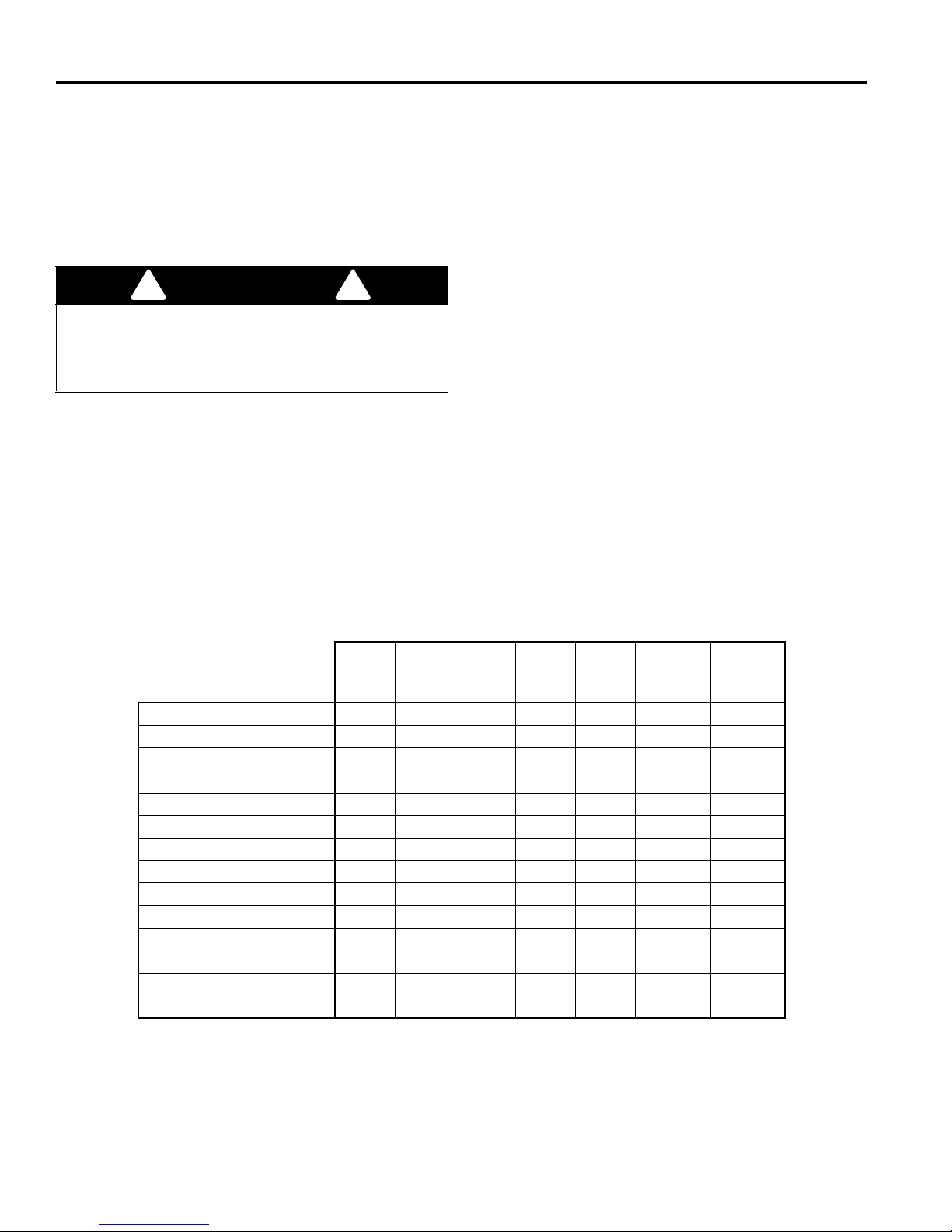
10 MAINTENANCE & LUBRICATION CHARTS
!
!
10 MAINTENANCE & LUBRICATION CHARTS
10.1 SPLOŠNO ________________________________________________________________
Kosilnica potrebuje minimalno podmzovanje. Premočno
podmazovanje močno obremeni tečaje in motor, kar
zmanjša učinkovitost delovanja kosilnice.
Vsa vzdrževalna dela se mor aj o iz va jat i pog os teje , kad ar
delo poteka v zelo prašnih pogojih.
OPOZORILO
Pred čiščenjem, prilagajanjem ali servisom vedno
3. Za tekoče delovanje osi, tečajev in trugih mest, kjer
prihaja do trenja, nanesite več kapljic olja SAE 30
vsakih 50 ur oziroma po potrebi.
4. Kadar podmazujete točke (L
in L7), odstranite le vo
6
kolo.
Odstranite vijak (A) iz konca osi in potegnite pesto
kolesa (D) iz osi. Odstr anite obroč (B) in obloge (C)
nato podmažite (L
) z litijevo mastjo.
7
izključite vse pogone, potegnite ročno zavoro, ustavite
motor in odstranite svečko za vžig, da preprečite
poškodbe.
Odstranite namestitveni nosilec (E) da dobite dostop
do točke (L
). obrnite pogonski boben, če ročica (F)
6
ovira dostop do mesta, nato pa s pištolo za nanos
1. Vedn o očistite nastavke za podmazovna nje, pred in
po podmazonvanju.
2. Podmazujte z mazivi, ki dosegajo ali presegajo
specifikacije NL GI stopnja 2 L B. Mazivo n anašajte z
maziva previdno nanesite mazivo skozi odprtino.
5. Za podmazovanje točke (L
), odstranite po krov (G)
10
in nanesite eno merico maziva na nastavek na
koncu osi.
ročno pištolo ša nanos maziv in počasi polnite,
dokler mazivo ne začne polzeti iz nastavka. Ne
uporabljajte stisnjenega zraka.
10.2 TABELA ZA VZDRŽEVANJE __________________ ___ ________________ ____________
Priporočljivi intervali za podmazovanje in pregled
Vsakih
8-10
ur
Zračni filter
Izgorevalna komora
Motorno olje
Cev za gorivo
Črpalka za gorivo
Svečka za vžig
Prostor med ventili
Nastavki za podmazovanje
L1 - L4
L5 - L6
L7
L8 - L9
L10
L11
Vsakih
20
ur
PO
PZ* Z I
NNII
D - Dodati ali popraviti O - Očistiti P - Pregledati N- Naoljiti Z - Zamanjati PP - Po potrebi
* Pri začetnem pregledu novga stroja.
I Motorno olje - Glej razdelek 8.3
II Ročna pištola za mazivo z NLGI Stopnje 2 (Razred LB).
III Lubriplate
®
mazivo, Jacobsen del št. 5001581
Vsakih
50
ur
Vsakih
100
PP
NNIII
ur
O
Vsakih
250
ur
O
D
N II
Letno Tip
Z - 2 leti
N II
N III
N II
maziva
28
Page 57
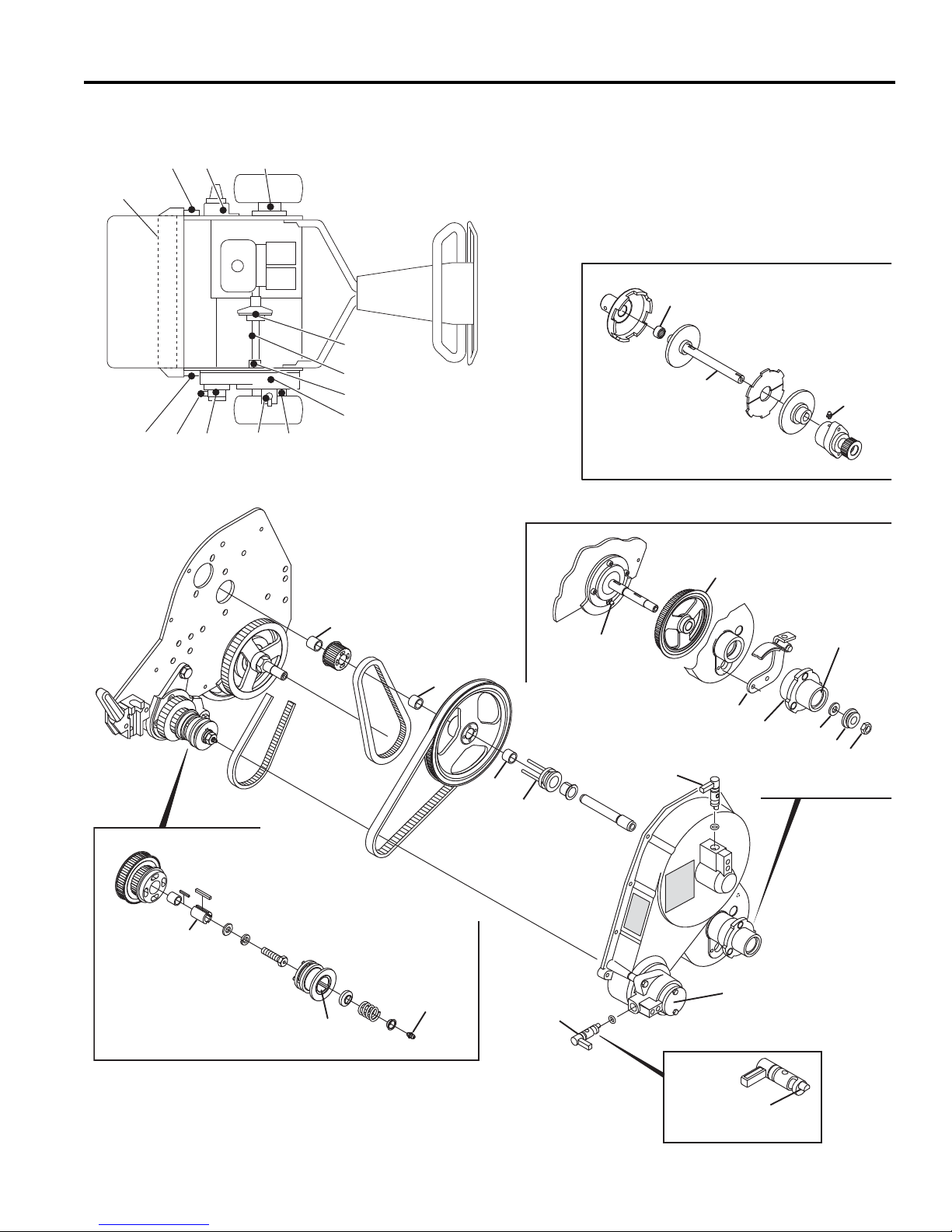
MAINTENANCE & LUBRICATION CHARTS 10
L
14
L
14
L
13
Æ
Æ
●
F
C
D
G
B
A
L
9
L
10
E
●
●
● - NLGI #2 Grease
Æ - Lubriplate
¨
Marine Grease
L
12
L
8
Æ
●
●
●
●
L
11
●
L
11-12
Apply Lubricant
L
6
L
7
Æ
●
L
5
●
L
3
L
4
L
5
L
6
L
7
L
8
L
9
L
10
L
11
L12L
13
L
14
L
2
L
2
L
1
10.3 TABELA ZA PODMAZOVANJE_______________________________________________
29
Page 58

1.1......................................Handle Attachment............................................................................................................................................................................. 31
2.1......................................Handle and Controls.......................................................................................................................................................................... 32
3.1......................................Frame Assembly................................................................................................................................................................................. 34
4.1......................................Lower Unit........................................................................................................................................................................................... 36
5.1......................................Reel...................................................................................................................................................................................................... 38
6.1......................................Engine and Clutch.............................................................................................................................................................................. 40
7.1......................................Engine Throttle and Clutch Cover.................................................................................................................................................... 42
8.1......................................Belts..................................................................................................................................................................................................... 44
9.1......................................Belt Cover ........................................................................................................................................................................................... 46
10.1....................................Weight Bars and Roller Brackets...................................................................................................................................................... 48
11.1....................................Differential and Rollers...................................................................................................................................................................... 50
12.1....................................Parking Brake and Wheels................................................................................................................................................................ 52
Page 59
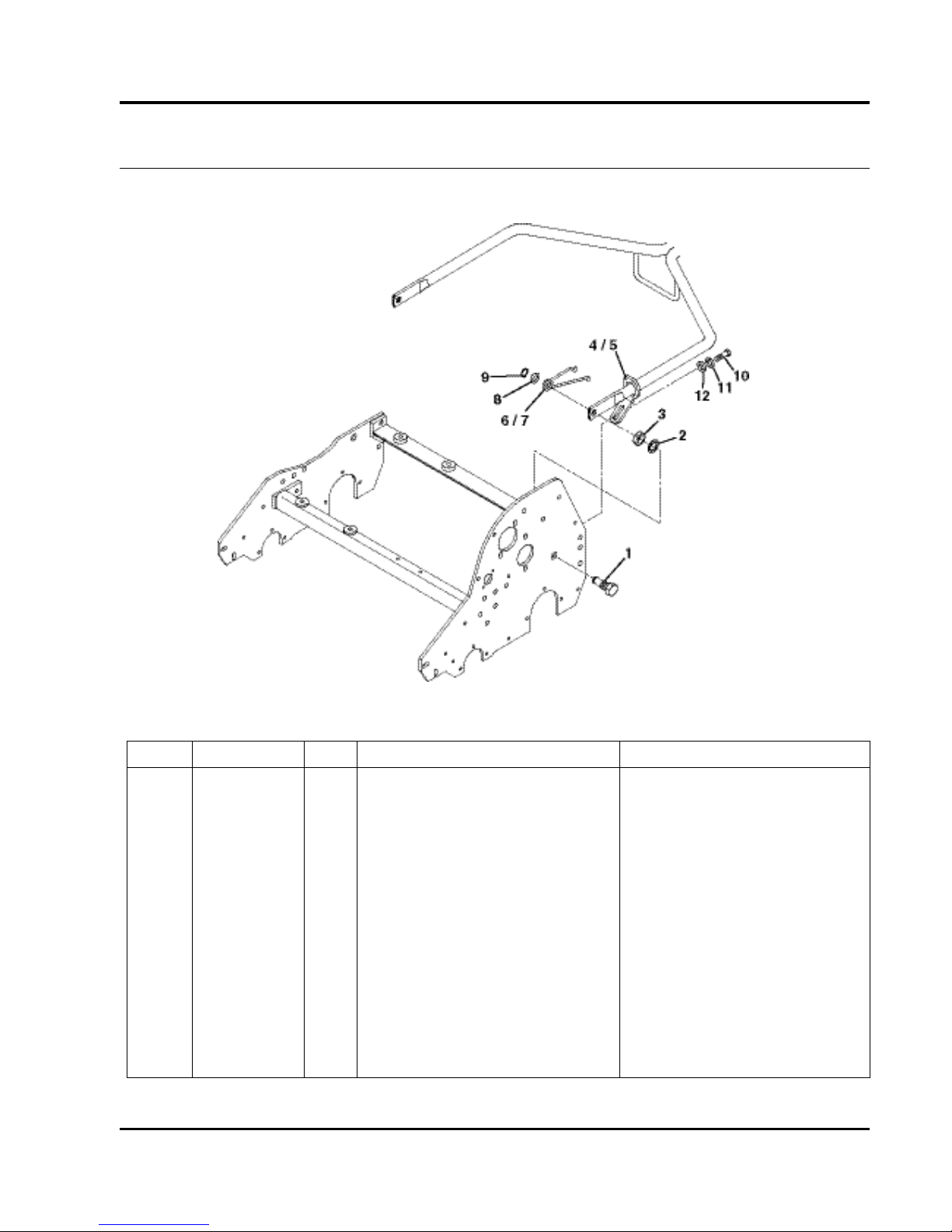
31
> Change from previous revision
GREENS KING 500A SERIES
1.1 Handle Attachment
Serial No. All
Item Part No. Qty. Description Serial Numbers/Notes
1
2811159 2 Bolt, Handle Mount
2 447224 2 Lockwasher, 5/8” Internal Tooth
3 443828 2 Nut, 5/8-18 Hex Jam
4 4115960 1 Right Side Handle Stop
5 4115961 1 Left Side Handle Stop
6 2809900 1 Left Side Torsion Spring
7 2809901 1 Right Side Torsion Spring
8 455012 2 Flat Washer, 3/4
9 458006 2 Retaining RIng, 1/2 Truarc
10 400262 2 Screw, 3/8-16 x 1” Hex Head
11 446142 2 Lockwasher, 3/8 Heavy
12 453011 2 Flat Washer, 3/8
Page 60
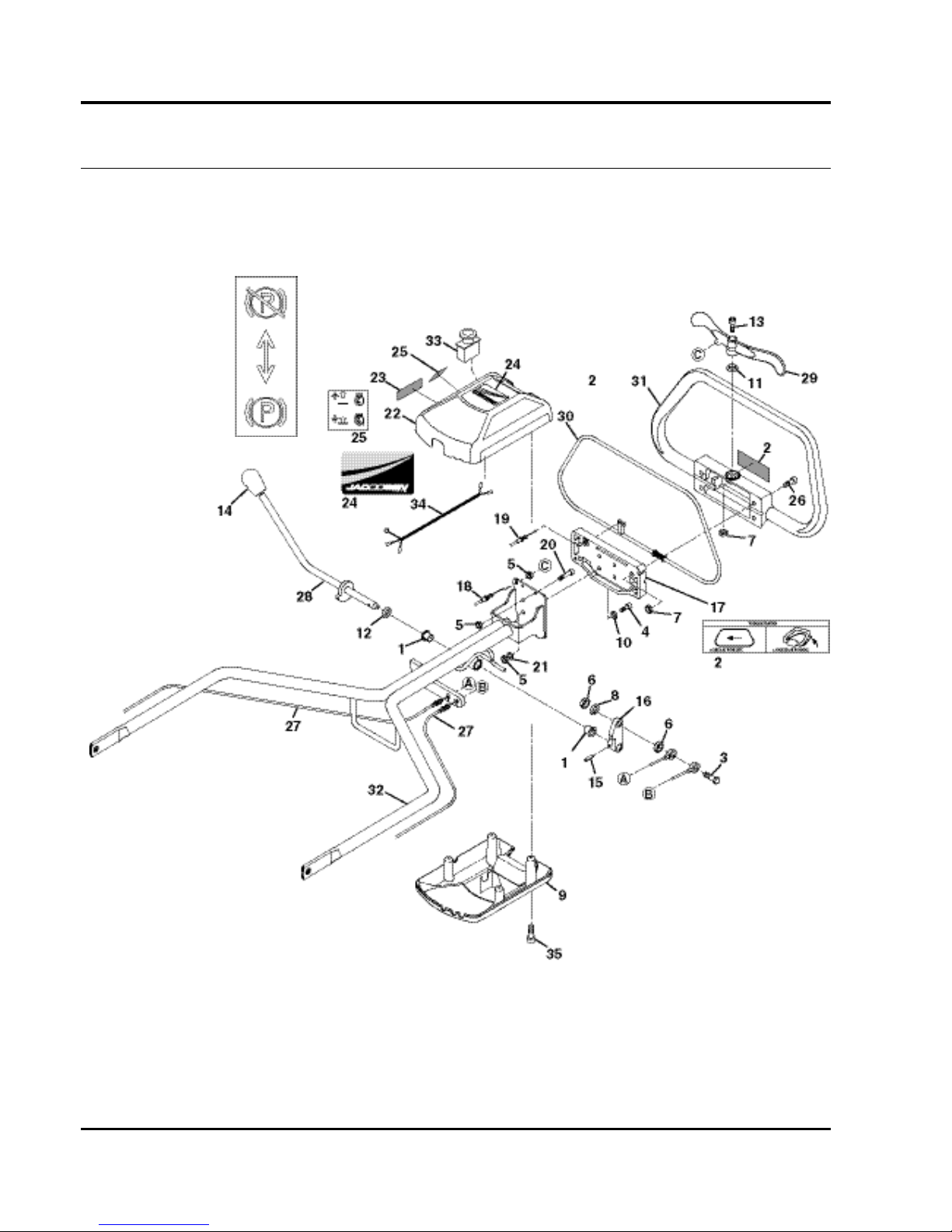
32
GREENS KING 500A SERIES
2.1 Handle and Controls
Serial No. All
23
Page 61

33
> Change from previous revision
Item Part No. Qty. Description Serial Numbers/Notes
1
366708 2 Flanged Bearing
2 4139678 1 Decal, Bail Operation
3 400268 1 Screw, 3/8-16 x 1-3/4” Hex Head
4 434029 4 Screw, 1/4-20 x 1” Socket Head
5 443102 7 Nut, 1/4-20 Hex
6 443110 2 Nut, 3/8-16 Hex
7 444718 5 Locknut, 5/16-18 Center
8 446142 1 Lockwasher, 3/8 Heavy
9 4127051 1 Cover, Back
10 453023 4 Flat Washer, 1/4
11 454008 1 Washer, 1/2 Spring
12 454008 AR Washer, 1/2 Spring
13 434032 1 Screw, 5/16-18 x 1-3/4” Socket Head
14 4127340 1 Knob
15 461181 1 Groove Pin, 3/16 x 3/4”
16 2000067 1 Lever, Brake
17 4136328 1 Plate, Tilt
18 4130475 1 Cable, Paddle Throttle See 6.1 for Engine Connection
19 4136550 1 Cable, Bail Throttle See 6.1 for Engine Connection
20 434010 2 Screw, 1/4-20 x 1-3/4 Socket Head
21 446130 4 Lockwasher, 1/4 Heavy
22 4147697 1 Cover, Front
23 3002753 1 • Decal, Parking Brake
24 4124759 1 • Decal, Jacobsen Emblem
25 4147495 1 • Decal, E-Stop
26 4128933 4 Screw, 5/16-18 x 1-1/2” Socket Head
27 4130474 2 Brake Cable
28 4131414 1 Lever, Brake
29 4136323 1 Plate, Throttle
30 4136325 1 Bail Lever
31 4147696 1 Handle, Overmolded
32 4130460 1 Handle, 518 Used on 63281 only
32 4130464 1 Handle, 522 Used on 63282 Only
32 4130468 1 Handle, 526 Used on 63285 only
33 4147835 1 E-Stop Switch
34 4147215 1 Harness, E-Stop
35 4128662 4 Screw, #10-32 x 3/8” Socket Head
GREENS KING 500A SERIES
Page 62
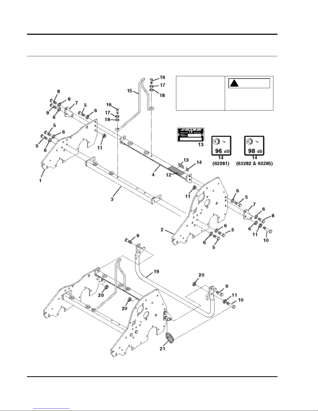
34
GREENS KING 500A SERIES
3.1 Frame Assembly
Serial No. All
12
! WARNING
Keep Bystanders Away. DoModel 518A 95.3 kg
Model 522A 101.2 kg
Model 526A 123.4 kg
2811102
Model 522TA 100.7 kg
Model PGM 19 84.0 kg
Model PGM 22 85.0 kg
Vehicle Mass:
Model TC22 101.1 kg
Not Operate Without Guards
In Place
Page 63

35
> Change from previous revision
GREENS KING 500A SERIES
Item Part No. Qty. Description Serial Numbers/Notes
1
2811122 1 Frame, R.H. Side
2 2811121 1 Frame, L.H. Side
3 1000022 1 518 Front Crossbar
3 1000839 1 522 Front Crossbar
3 1000023 1 526 Front Crossbar
4 1000020 1 518 Rear Crossbar
4 1000838 1 522 Rear Crossbar
4 1000021 1 526 Rear Crossbar
5 400258 6 Screw, 3/8-16 x 3/4” Hex Head
6 446142 10 Lockwasher, 3/8 Heavy
7 366796 2 Kickstand, Mounting Bracket
8 400262 2 Screw, 3/8-16 x 1” Hex Head
9 400260 3 Screw, 3/8-16 x 7/8” Hex Head
10 400268 2 Screw, 3/8-16 x 1-3/4” Hex Head
11 443810 4 Nut, 3/8-16 Hex Jam
12 2811102 1 Decal, Warning
13 REF 1 Serial Plate
14 4117466 1 Decal, 96 db Noise Used on 63281 Only
14 4131528 1 Decal, 98 db Noise Used on 63282, 63285 Only
15 3006118 1 Hook, Lift
16 400188 2 Screw, 5/16-18 x 1” Hex Head
17 446136 2 Lockwasher, 5/16 Heavy
18 364441 2 Spacer
19 1000018 1 518 Kickstand
19 132674 1 522 Kickstand
19 1000019 1 526 Kickstand
20 444850 3 Nut, 3/8-16 Center Lock Jam
21 364164 1 Spring
Page 64
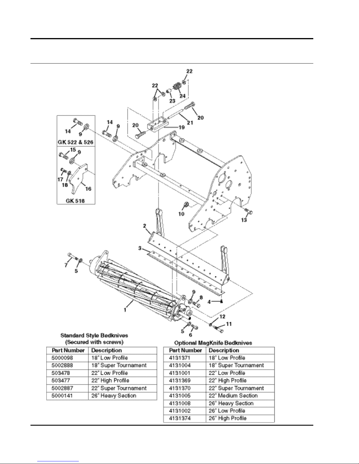
36
GREENS KING 500A SERIES
4.1 Lower Unit
Serial No. All
Page 65

37
> Change from previous revision
GREENS KING 500A SERIES
Item Part No. Qty. Description Serial Numbers/Notes
1
REF 1 Reel Assembly See 5.1
2 5000102 1 Bedknife Backing, 518 Standard Standard
2 4130295 1 Bedknife Backing, 518 Magknife Magknife Option
2 5000457 1 Bedknife Backing, 522 Standard Standard
2 4130281 1 Bedknife Backing, 522 Magknife Magknife Option
2 5000412 1 Bedknife Backing, 526 Standard Standard
2 4130286 1 Bedknife Backing, 526 Magknife Magknife Option
3 REF 1 Bedknife See Chart
4 3009138 AR Screw, 1/4-20 x 3/4 Soc. Hd.
5 446136 6 Lockwasher, 5/16 Heavy
6 434051 3 Screw, 5/16-18 x 1/2” Socket Head
7 434036 3 Screw, 5/16-18 x 1-1/4” Socket Hd.
8 400264 2 Screw, 3/8-16 x 1-1/4 Hex Head
9 446142 5 Lockwasher, 3/8 Heavy
10 443110 2 Nut, 3/8-16 Hex
11 365501 2 Bolt, Bedknife Shoe
12 454017 2 Shim, Bedknife Shoe
13 400256 3 Screw, 3/8-16 x 5/8” Hex Head
14 400258 2 Screw, 3/8-16 x 3/4” Hex Head 63281
14 400258 3 Screw, 3/8-16 x 3/4” Hex Head 63282 and 63285
15 400264 1 Screw, 3/8-16 x 1-1/4” Hex Head Used on 63281 Only
16 3001644 1 Weight Used on 63281 Only
17 400114 1 Screw, 1/4-20 x 1-1/4” Hex Head Used on 63281 Only
18 446130 1 Lockwasher, 1/4 Heavy Used on 63281 Only
19 3001600 2 Bedknife Block
20 366726 4 Bolt, Special
21 366727 2 Rod
22 366653 6 Spacer
23 367512 2 Spacer
24 366709 2 Spring
Page 66
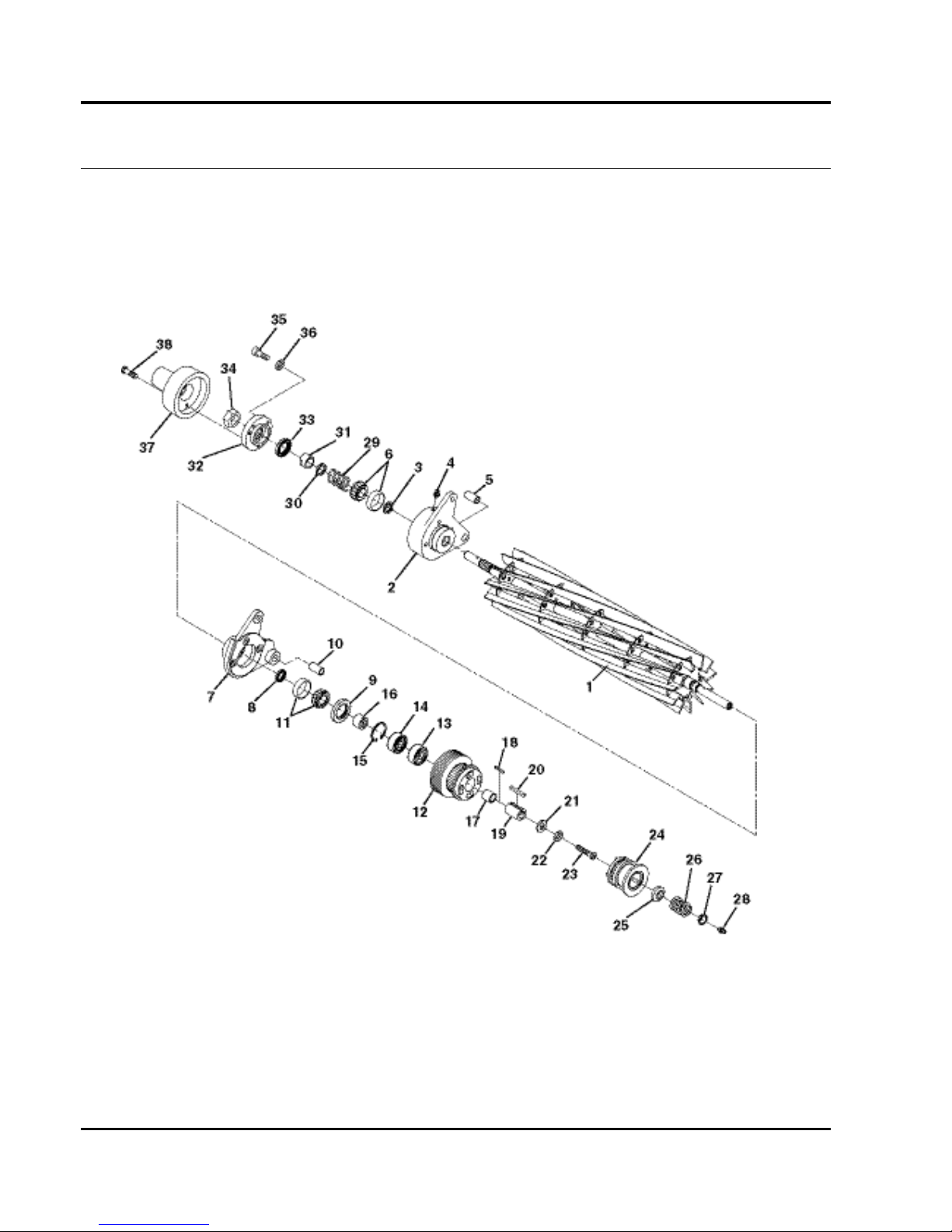
38
GREENS KING 500A SERIES
5.1 Reel
Serial No. All
Page 67

39
> Change from previous revision
GREENS KING 500A SERIES
Item Part No. Qty. Description Serial Numbers/Notes
1
5000095 1 Reel, 18” Used on 518
1 5000148 1 Reel, 22” 11 Blade Used on 522
1 5003652 1 Reel, 26” 7 Blade
2 1000447 1 Bearing Housing
3 366650 1 • Seal
4 4128725 1 • Grease Fitting
5 545940 1 • Bushing
6 500534 1 • Bearing Cup and Cone
7 1000446 1 Bearing Housing
8 366650 1 • Grease Seal
9 366649 1 • Grease Seal
10 545940 1 • Bushing
11 500534 1 • Bearing Cup and Cone
12 2811185 1 Pulley
13 365229 1 • Bearing With Seal
14 366652 1 • Bearing
15 458461 1 • Snap Ring
16 366645 1 Spacer
17 366646 1 Spacer
18 345556 1 Key, 1/8 Square x 1”
19 340462 1 Spacer
20 320774 2 Key, 3/16 Square x 1-1/4”
21 366653 1 Washer
22 446142 1 Lockwasher, 3/8 Heavy
23 366651 1 Bolt
24 5002727 1 Reel Clutch
25 3004368 1 Spring Retainer
26 3006061 1 Spring
27 3004369 1 Spring Retainer
28 471217 1 Grease Fitting
29 363047 1 Spring
30 304745 1 Washer
31 364900 1 Nut
32 164041 1 Seal Carrier
33 366648 1 • Grease Seal
34 367029 1 Nut, 3/4-16 Hex Nylock Jam
35 434028 3 Screw, 1/4-20 x 3/4” Socket Head
36 446130 3 Lockwasher, 1/4 Heavy
37 4136845 1 Cover
38 2811566 2 Screw, 1/4-20 x 12” Socket Head
Page 68
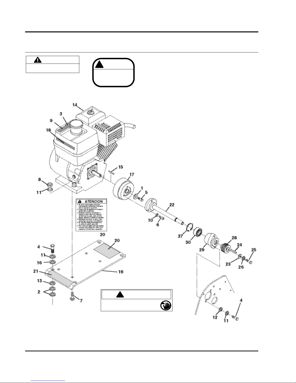
40
GREENS KING 500A SERIES
6.1 Engine and Clutch
Serial No. All
BE SURE THE TRACTION CLUTCH
LEVER IS IN NEUTRAL BEFORE
STARTING THE ENGINE.
CAUTION
3
ALLOW ENGINE
TO COOL FOR 2
MINUTES BEFORE
REFUELING
! CAUTION
9
!
DANGER
To avoid serious bodily injury stop engine
and disengage reels before working on
mower or emptying baskets.
21
Page 69

41
> Change from previous revision
GREENS KING 500A SERIES
Item Part No. Qty. Description Serial Numbers/Notes
1
303873 1 Washer
2 348849 AR Shim, 0.01”
3 362764 1 Decal, Refueling Caution
4 400188 6 Screw, 5/16-18 x 1” Hex Head
5 306369 1 Screw, 5/16-24 x 3/4” Hex Head
6 434029 3 Screw, 1/4-20 x 1” Socket Head
7 441677 4 Carriage Bolt, 5/16-18 x 1-1/2”
8 443106 4 Nut, 5/16-18 Hex
9 3001790 1 Decal, Caution
10 446130 3 Lockwasher, 1/4 Heavy
11 446136 8 Lockwasher, 5/16 Heavy
12 453009 2 Flat Washer, 5/16
13 3005515 AR Shim, 0.02”
14 503532 1 Engine, 4HP Honda
15 320774 1 • Key, 3/16 x1-1/2” Square
16 364441 4 Spacer
17 4135990 1 Torque Clutch Engages at 2000 RPM
18 2811096 1 Decal, Greens King 518A
18 2811097 1 Decal, Greens King 522A
18 2811099 1 Decal, Greens King 526A
19 5002848 1 Engine Base Includes Decals
20 340830 1 • Decal, Spanish
21 3001235 1 • Decal, Danger
22 4136559 1 Clutch Shaft, 518 Used on 63281 only
22 4136557 1 Clutch Shaft, 522 Used on 63282 Only
22 4136544 1 Clutch Shaft, 526 Used on 63285 only
23 366653 1 • Spacer
24 367082 1 • Key,
25 400262 1 • Screw, 3/8-16 x 1” Hex Head
26 446142 1 • Lockwasher, 3/8 Heavy
27 458113 1 • Snap Ring
28 3007847 1 • Pulley
29 4137242 1 • Housing, Bearing
30 4137243 1 • Bearing
Page 70
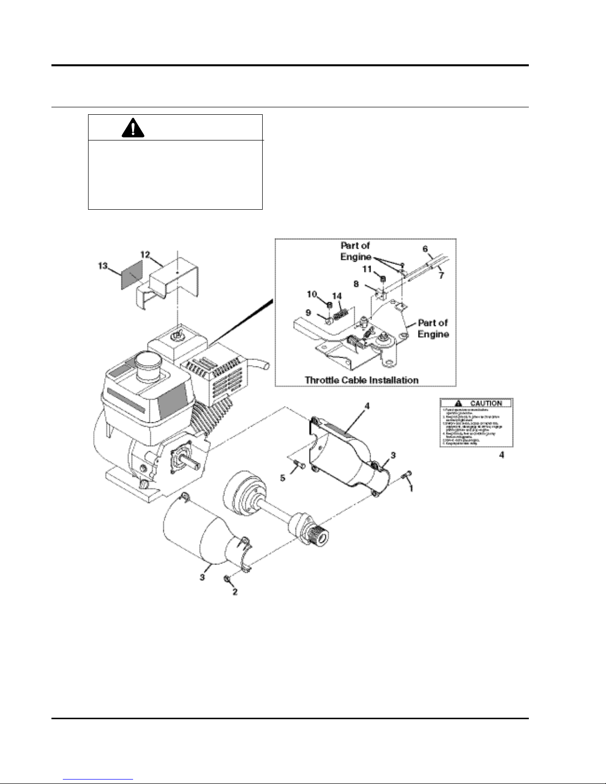
42
GREENS KING 500A SERIES
7.1 Engine Throttle and Clutch Cover
Serial No. All
TO PREVENT INJURY AND ACCIDENTAL
CLUTCH ENGAGEMENT DO NOT ADJUST
ENGINE SPEED USING THROTTLE LEVER
ON ENGINE. ALWAYS ADJUST ENGINE
SPEED USING THE OPC HANDLE AND
THROTTLE PADDLE
WARNING
4146636
13
Page 71

43
> Change from previous revision
GREENS KING 500A SERIES
Item Part No. Qty. Description Serial Numbers/Notes
1
400108 4 Screw, 1/4-20 x 3/4” Hex Head
2 444708 4 Locknut, 1/4-20 Center
3 4148537 1 Cover, 18” Clutch Used on 518, Includes Decal
3 4148538 1 Cover, 22” Clutch Used on 522, Includes Decal
3 4147698 1 Cover, 26” Clutch Used on 526, Includes Decal
4 361854 1 • Decal, Warning
5 400218 2 Screw, 5/16-24 x 1/2” Hex Head
6 REF 1 Cable, Paddle Throttle See 2.1
7 REF 1 Cable, Bail Throttle See 2.1
8 4136549 1 Guide, Cable
9 4136554 1 Collar, Cable Stop
10 4137299 1 • Set Screw, #6-32
11 4137299 1 Set Screw, #6-32 x 3/16” Cup
12 4147695 1 Throttle Cover
13 4146636 1 • Decal, Throttle Warning
14 4108643 1 Spring, Throttle Plate
Page 72
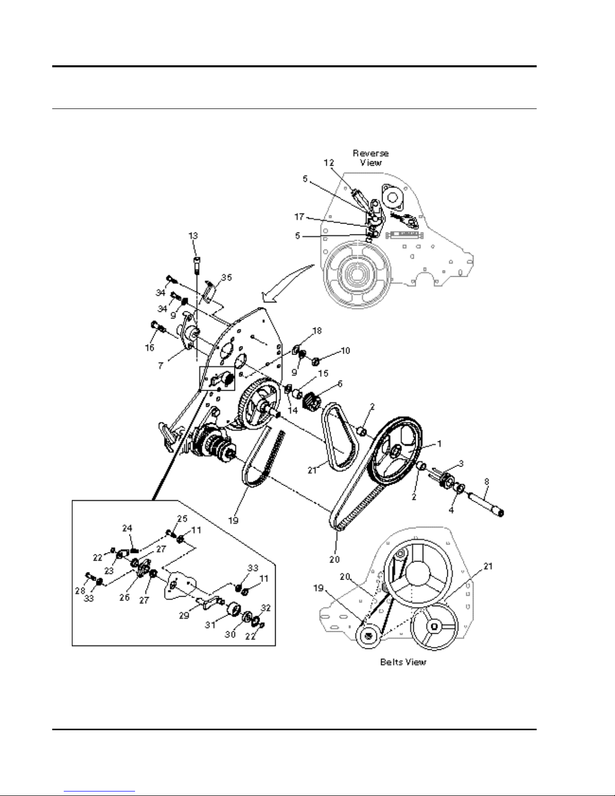
44
GREENS KING 500A SERIES
8.1 Belts
Serial No. All
Page 73

45
> Change from previous revision
GREENS KING 500A SERIES
Item Part No. Qty. Description Serial Numbers/Notes
1
503685 1 Pulley, 80 Tooth
2 367554 2 • Needle Bearing
3 1000056 1 Traction Clutch
4 366725 1 Flanged Bushing
5 443106 2 Nut, 5/16-18 Hex
6 5002447 1 Pulley, 18 Tooth
7 2000148 1 Bearing Bracket
8 3001273 1 Shaft
9 446142 3 Lockwasher, 3/8 Heavy
10 443110 2 Nut, 3/8-16 Hex
11 443102 7 Nut, 1/4-20 Hex
12 2500485 1 Screw, 5/16-18 x 3-1/4” Hex Head
13 434031 1 Screw, 1/4-20 x 3/4” Socket Head
14 359864 AR Washer
15 367553 1 Needle Bearing
16 400262 2 Bolt, 3/8-16 x 1”
17 400188 1 Screw, 5/16-18 x 1” Hex Head
18 453011 2 Washer
19 2810713 1 Belt, 7 Rib Micro V
20 2811363 1 Belt, 112 Tooth
21 2811071 1 Belt, 80 Tooth
22 458006 2 Retaining Ring
23 2809667 1 Bracket, Idler Spring
24 2809669 1 Spring, Idler
25 400116 1 Screw, 1/4-20 x 1-1/2” hex Head
26 4130965 1 Bracket, Idler
27 352936 2 Bushing
28 400106 2 Screw, 1/4-20 x 5/8” Hex Head
29 2809665 1 Arm, Idler
30 344545 1 Bearing
31 2809666 1 Pulley, Idler
32 458105 1 Retaining Ring
33 446128 2 Lockwasher, 1/4
34 400254 2 Screw, 3/8-16 x 1/2” Hex Head
35 3009434 1 Bracket, Belt Adjusting
Page 74
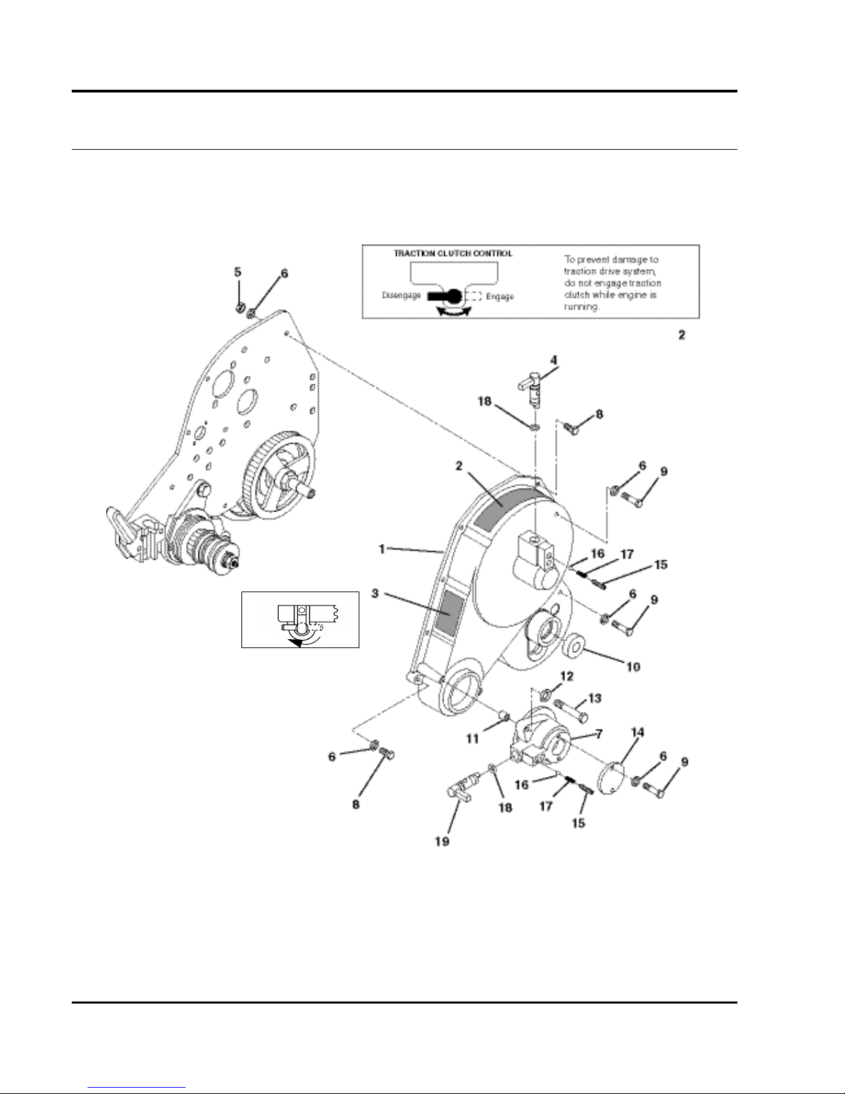
46
GREENS KING 500A SERIES
9.1 Belt Cover
Serial No. All
REEL CLUTCH CONTROL
ENGAGEDISENGAGE
J-T-3001792
3
Page 75

47
> Change from previous revision
GREENS KING 500A SERIES
Item Part No. Qty. Description Serial Numbers/Notes
1
503638 1 Belt Cover
2 2811092 1 • Decal, Warning
3 3001792 1 • Decal, Reel Clutch
4 3000660 1 Traction Clutch Lever
5 443102 3 Nut, 1/4-20 Hex
6 446130 12 Lockwasher, 1/4 Heavy
7 220317 1 Shifter Housing
8 400112 6 Screw, 1/4-20 x 1-1/4” Hex Head
9 400106 5 Screw, 1/4-20 x 5/8” Hex Head
10 366707 1 Ball Bearing
11 366715 2 Spacer
12 446136 2 Lockwasher, 5/16 Heavy
13 400196 2 Screw, 5/16-18 x 2” Hex Head
14 366710 1 Cover
15 422522 4 Set Screw, 3/8-16 x 1/2” Socket Hd.
16 343850 4 Ball, 1/4” Diameter
17 343848 2 Spring
18 339910 2 “O”Ring
19 3004402 1 Shifter Shaft
Page 76
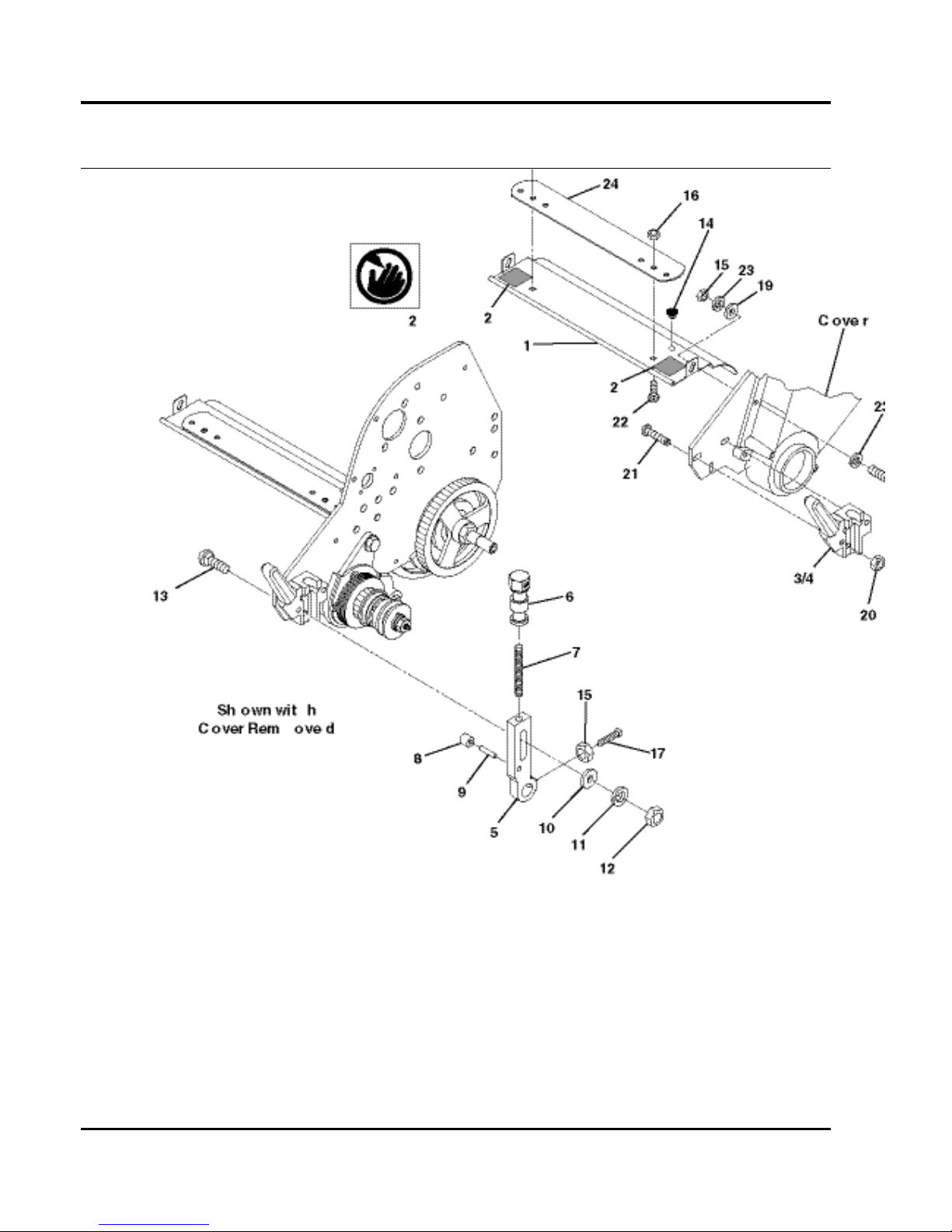
48
GREENS KING 500A SERIES
10.1 Weight Bars and Roller Brackets
Serial No. All
Page 77

49
> Change from previous revision
GREENS KING 500A SERIES
Item Part No. Qty. Description Serial Numbers/Notes
1 4139661 1 Grass Shield (518A) Used on 63281 Only
1 4139660 1 Grass Shield (522A) Used on 63282 Only
1 4139662 1 Grass Shield (526A) Used on 63285 Only
2 4127335 2 • Decal, Danger
3 241827 1 L.H. Catcher Mounting Bracket
4 241828 1 R.H. Catcher Mounting Bracket
5 2000072 2 Roller Bracket
5 2000040 2 Roller Bracket Used on 63285 Only
6 3005692 2 Adjuster Knob
7 343616 2 Stud
8 366852 2 Spacer
9 461339 2 Pin, 1/4 x 1-1/4”
10 364441 2 Washer
11 446136 2 Lockwasher, 5/16 Heavy
12 443106 2 Nut, 5/16-18 Hex
13 441674 2 Carriage Bolt 5/16-18 x 1-3/4”
14 3008974 4 Grommet
15 443102 4 Nut, 1/4-20 Hex
16 445781 2 Nut, 5/16-18 Whiz Lock
17 352737 2 Screw, 1/4-20 x 7/8” Square Head
18 400112 2 Screw, 1/4-20 x 1-1/4” Hex Head
19 453023 2 Flat Washer
20 444718 4 Locknut, 5/16-18 Center
21 441677 4 Carriage Bolt, 5/16-18 x 1-1/4”
22 441614 2 Carriage Bolt, 5/16-18 x 1”
23 446130 2 Lockwasher, 1/4 Heavy
24 3000053 2 Plate
25 68122 1 518 Grass Catcher
25 68123 1 522 Grass Catcher
25 68124 1 526 Grass Catcher
Page 78
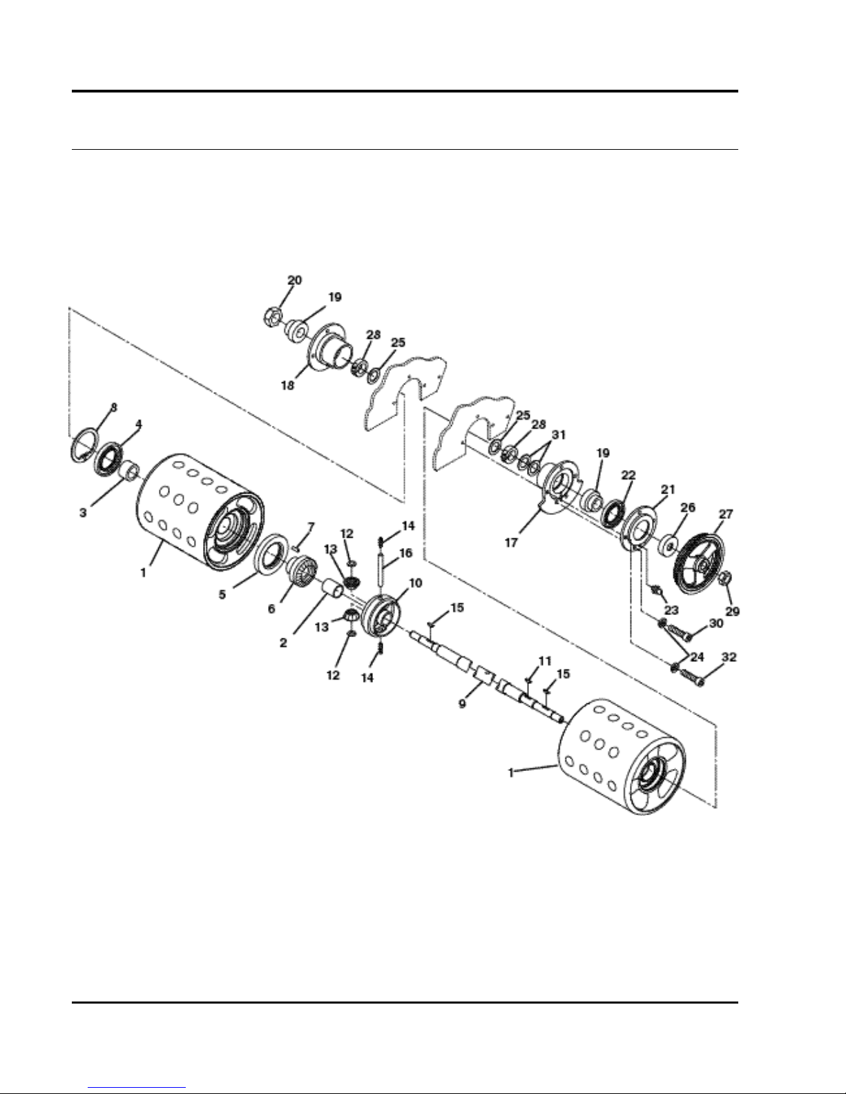
50
GREENS KING 500A SERIES
11.1 Differential and Rollers
Serial No. All
Page 79

51
> Change from previous revision
GREENS KING 500A SERIES
Item Part No. Qty. Description Serial Numbers/Notes
1 1000024 2 Smooth Roller (518)
1 132655 2 Smooth Roller (522)
1 1000027 2 Dimpled Roller (526)
2 366699 1 • Differential Gear Bushing
3 366698 1 • Drum Bushing
4 366701 1 • Grease Seal
5 366700 1 • Grease Seal
6 241836 1 • Differential Gear
7 319085 1 • Pin
8 458127 1 • Snap Ring
9 395419 1 Roller Shaft (518)
9 395367 1 Roller Shaft (522)
9 395418 1 Roller Shaft (526)
10 241835 1 Differential
11 463017 1 Key, #9 Woodruff
12 308030 2 Thrust Washer
13 202947 2 Pinion Gear
14 415563 2 Set Screw, 7/16-20 x 3/8”
15 463007 2 Key, #7 Wooodruff
16 308028 1 Pinion Shaft
17 220318 1 Bearing Housing
18 220319 1 Bearing Housing
19 366693 2 Bearing
20 2810096 1 Nut, 1-14 Nylock Hex
21 164057 1 Seal Cover
22 366702 1 • Grease Seal
23 471214 1 • Grease Fitting
24 446136 5 Lockwasher,5/16 Heavy
25 366697 2 Spacer
26 366696 1 Spacer
27 3004484 1 Pulley, 56 Tooth
28 366695 2 Locking Collar
29 367029 1 Nut, 3/4-16 Hex Nylock Jam
30 434024 2 Screw, 5/16-18 x 3/4” Socket Hd
31 361451 2 Washer
32 434004 3 Screw, 5/16-18 x 1-3/4” Soc Hd
Page 80
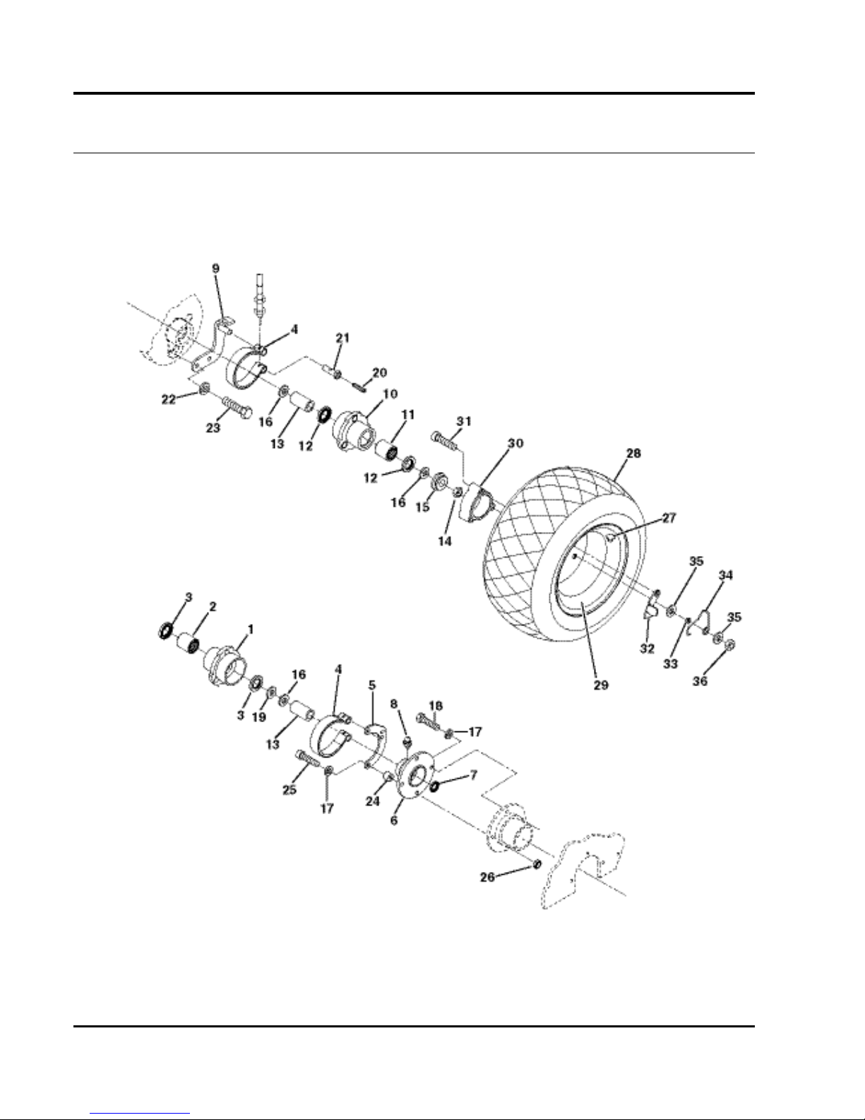
52
GREENS KING 500A SERIES
12.1 Parking Brake and Wheels
Serial No. All
Page 81

53
> Change from previous revision
GREENS KING 500A SERIES
Item Part No. Qty. Description Serial Numbers/Notes
1
1000476 1 R.H. Hub
2 338766 1 • Bearing
3 366705 2 • Grease Seal
4 164056 2 Brake Band
5 132663 1 Brake Mounting Bracket
6 132658 1 Seal Housing
7 365753 1 • Grease Seal
8 4128725 1 • Grease Fitting
9 164063 1 Brake Mounting Bracket
10 1000477 1 L.H. Hub
11 338766 1 • Bearing
12 366705 2 • Grease Seal
13 366717 2 Clutch Sleeve
14 445801 2 Nut, 5/8-18 Hex Jam Lock
15 366718 2 Latching Collar
16 366697 4 Bushing
17 446136 4 Lockwasher, 5/16 Heavy
18 400188 2 Screw, 5/16-18 x 1” Hex Head
19 361451 1 Washer Left Side Only
20 415513 2 Set Screw, 1/4-20 x 1/2”
21 366742 2 Brake Band Pin
22 446130 2 Lockwasher, 1/4 Heavy
23 400108 2 Screw, 1/4-20 x 3/4” Hex Head
24 366737 2 Spacer
25 434032 2 Screw, 5/16-18 x 1-3/4” Socket Head
26 443106 1 Nut, 5/16-18 Hex
62293 1 Pneumatic Transport Tire Kit Optional Accessory
27 360111 2 • Valve
28 554847 2 • Tire
29 5002905 2 • Wheel, Gray
30 271920 2 • Wheel Spacer
31 434049 6 • Screw, 5/16-18 x 2” Socket Head
32 366719 2 • Latch
33 366716 6 • Spacer
34 366704 2 • Spring
35 452004 12 • Flat Washer, 5/16
36 444718 6 • Locknut, 5/16-18 Center
Page 82

54
INDEX
1000018................................35
1000019................................35
1000020................................35
1000021................................35
1000022................................35
1000023................................35
1000024................................51
1000027................................51
1000056................................45
1000446................................39
1000447................................39
1000476................................53
1000477................................53
1000838................................35
1000839................................35
132655..................................51
132658..................................53
132663..................................53
132674..................................35
164041..................................39
164056..................................53
164057..................................51
164063..................................53
2000040................................49
2000067................................33
2000072................................49
2000148................................45
202947..................................51
220317..................................47
220318..................................51
220319..................................51
241827..................................49
241828..................................49
241835..................................51
241836..................................51
2500485................................45
271920..................................53
2809665................................45
2809666................................45
2809667................................45
2809669................................45
2809900................................31
2809901................................31
2810096................................51
2810713................................45
2811071................................45
2811092................................47
2811102................................35
2811121................................35
2811122................................35
2811159................................31
2811185................................39
2811363................................45
2811566................................39
3000053................................49
3000660................................47
3001235 ...............................41
3001273 ...............................45
3001600 ...............................37
3001644 ...............................37
3001792 ...............................47
3002753 ...............................33
3004368 ...............................39
3004369 ...............................39
3004402 ...............................47
3004484 ...............................51
3005692 ...............................49
3006061 ...............................39
3006118 ...............................35
3007847 ...............................41
3008974 ...............................49
3009138 ...............................37
3009434 ...............................45
303873 .................................41
304745 .................................39
308028 .................................51
308030 .................................51
319085 .................................51
320774 .......................... 39, 41
338766 .................................53
339910 .................................47
340462 .................................39
340830 .................................41
343616 .................................49
343848 .................................47
343850 .................................47
345556 .................................39
352737 .................................49
352936 .................................45
359864 .................................45
360111 .................................53
361451 .......................... 51, 53
361854 .................................43
363047 .................................39
364164 .................................35
364441 .................................35
364900 .................................39
365229 .................................39
365501 .................................37
365753 .................................53
366645 .................................39
366646 .................................39
366648 .................................39
366649 .................................39
366650 .................................39
366651 .................................39
366652 .................................39
366653 ....................37, 39, 41
366693 .................................51
366695 .................................51
366696 .................................51
366697 .......................... 51, 53
366698.................................51
366699.................................51
366700.................................51
366701.................................51
366702.................................51
366704.................................53
366705.................................53
366707.................................47
366708.................................33
366709.................................37
366710.................................47
366715.................................47
366717.................................53
366718.................................53
366719.................................53
366725.................................45
366726.................................37
366727.................................37
366737.................................53
366742.................................53
366796.................................35
366852.................................49
367029...........................39, 51
367082.................................41
367512.................................37
367553.................................45
367554.................................45
395367.................................51
395418.................................51
395419.................................51
4108643...............................43
4115960...............................31
4115961...............................31
4117466...............................35
4124759...............................33
4127051...............................33
4127335...............................49
4127340...............................33
4128662...............................33
4128725.........................39, 53
4128933...............................33
4130460...............................33
4130464...............................33
4130468...............................33
4130475...............................33
4130762...............................33
4130965...............................45
4131414...............................33
4131528...............................35
4135990...............................41
4136323...............................33
4136325...............................33
4136328...............................33
4136544...............................41
4136549...............................43
4136550...............................33
4136554............................... 43
4136557............................... 41
4136559............................... 41
4136845............................... 39
4137242............................... 41
4137243............................... 41
4137299............................... 43
4139660............................... 49
4139661............................... 49
4139662............................... 49
4146636............................... 43
4147215............................... 33
4147495............................... 33
4147695............................... 43
4147696............................... 33
4147697............................... 33
4147698............................... 43
4147835............................... 33
4148537............................... 43
4148538............................... 43
5000095............................... 39
5000148............................... 39
5002447............................... 45
5002727............................... 39
5002848............................... 41
5002905............................... 53
5003652............................... 39
500534................................. 39
503532................................. 41
503638................................. 47
503685................................. 45
545940................................. 39
554847................................. 53
68122................................... 49
68123................................... 49
68124................................... 49
To prevent damage to the reel
and.................13, 16
Page 83

Page 84

 Loading...