


Technical Manual
4325163-Rev B
HoverKing
32251 – 20 Inch (50.8 cm) HoverKing
32252 – 20 Inch (50.8 cm) Metal Blade Kit
32253 – 20 Inch (50.8 cm) Plastic Blade Kit
32254 – 20 Inch (50.8 cm) String Cutter Kit
32255 – 20 Inch (50.8 cm) Handle Extension Accessory
32257 – 16 Inch (40.6 cm) HoverKing
32258 – 16 Inch (40.6 cm) Metal Blade Kit
32259 – 16 Inch (40.6 cm) Plastic Blade Kit
32260 – 16 Inch (40.6 cm) String Cutter Kit
32261 – 16 Inch (40.6 cm) Handle Extension Accessory
32256 – Wheel Kit
™
WARNING
Warning: If incorrectly used, this machine can
cause severe injury. Those who use and maintain
this machine should be trained in its proper use,
warned of its dangers, and must read the entire
manual before attempting to set up, operate, adjust,
or service the machine.
GB

FOREWORD
This manual contains safety, operating, adjustment,
maintenance, troubleshooting instructions and parts list
for your new Jacobsen machine. This manual should be
stored with the equipment for reference during operation.
The serial plate is located on the deck housing. Jacobsen
recommends you record these numbers below for easy
reference.
Before you operate your machine, you and each operator
you employ should read the manual carefully in its
entirety. By following the safety, operating and
maintenance instructions, you will prolong the life of your
equipment and maintain its maximum efficiency.
If additional information is needed, contact your
Jacobsen Dealer.
A Textron Company
CHARLOTTE NC PRODUCT OF U.S.A.
®
Suggested Stocking Guide
To Keep your Equipment fully operational and productive, Jacobsen suggests you maintain a stock of the more
commonly used maintenance items. We have included part numbers for additional support materials and training aids.
To order any of the following material:
1. Write your full name and complete address on your
order form.
2. Explain where and how to make shipment:
❑ UPS ❑ Regular Mail
❑ Overnight ❑ 2nd Day
3. Order by the quantity desired, the part number, and
the description of the part.
4. Send or bring the order to your authorized Jacobsen
Dealer.
Service Parts
Qty. Part No. Description Qty. Part No. Description
4325116 Metal Blade (Package of 3) 4325134 1/2” HOC Spacer
4325126 Plastic Blade (Package of 6) 4325117 Blade Bolt, Metal Blade (Black)
4325146 String Cutter (Package of 50) 4325126 Blade Bolt, Plastic Blade (Silver)
4325118 20 Inch (508 mm) Blade Disk Washer
4325148 16 Inch (406 mm) Blade Disk Washer
Service Support Material
Qty. Part No. Description
4325163 Technical Manual
© 2015, Jacobsen, A Textron Company/Textron Innovations Inc.
“All rights reserved, including the right to reproduce this material
or portions thereof in any form.”
Qty. Part No. Description
Proposition 65 Warning
This product contains or emits
chemicals known to State of California
to cause cancer and birth defects or
other reproductive harm.
2
LITHO IN U.S.A. 7-2015

Table of Contents
Introduction
1.1 Important............................................................................. 1
1.2 Product Identification ..........................................................2
1.3 Serial Number .....................................................................2
1.4 Guidelines for the Disposal of Scrap Products ...................3
Safety
2.1 How to Operate Safely........................................................ 4
Specifications
3.1 Engine Specifications..........................................................8
3.2 Dimensions and Weights ....................................................9
3.3 Cutting Unit Specification.................................................. 11
3.4 Recommended Lubricants ................................................11
3.5 Accessories.......................................................................11
3.6 Support Literature .............................................................12
Decals
4.1 Safety Decals.................................................................... 13
Set-up
5.1 General .............................................................................14
5.2 Initial Inspection ................................................................14
5.3 Engine Oil .........................................................................14
5.4 Handle Assembly ..............................................................15
5.5 Handle Mounting Holes.....................................................15
5.6 Blade Disk Torque ............................................................15
Controls
6.1 Handle Controls ................................................................16
6.2 Engine Controls ................................................................17
Operation
7.1 Daily Inspection.................................................................19
7.2 OPC System .....................................................................19
7.3 Operating Procedure.........................................................20
7.4 Starting The Engine ..........................................................21
7.5 To Stop The Engine..........................................................22
7.6 Mowing..............................................................................22
Maintenance and Lubrication Charts
8.1 Maintenance Chart............................................................23
Maintenance
9.1 General Precautions .........................................................24
9.2 Engine...............................................................................24
9.3 Engine Oil .........................................................................25
9.4 Engine Air Filter ................................................................25
9.5 Fuel ...................................................................................26
9.6 Engine Exhaust.................................................................26
9.7 Inspecting Cutter Disk.......................................................27
9.8 Care and Cleaning ............................................................28
9.9 Mower Storage..................................................................29
Adjustments
10.1 General Precautions .......................................................30
10.2 Height of Cut (HOC)........................................................30
10.3 Bail Cable Adjustment (20 inch Mowers) ........................31
10.4 Torque Specification .......................................................32
Problem Solving
11.1 General ...........................................................................33
Notes
Parts List
13.1 How To Use The Parts Catalog ......................................36
13.2 To Order Parts ................................................................36
13.3 Parts Catalog Table of Contents.....................................36

1 INTRODUCTION
1Introduction
1.1 IMPORTANT______________________________________________________________
The Jacobsen HoverKing is a walk behind rotary mower.
If you follow all instructions in this manual, you increase the life of your mower and keep its maximum performance. The
adjustments and maintenance must always be done by an approved technician.
IMPORTANT: Do the maintenance included in this manual to make sure that the quality of cut is kept at a high level.
This SAFETY, OPERATION AND MAINTENANCE MANUAL is part of the mower and must stay with the mower always.
Suppliers of both original and used mowers need to keep the documentation that comes with the mower.
You must use the mower to cut the grass and not for any other purpose. Compliance with the conditions or operation,
service and repair specified by the manufacturer, are understood to be part of the correct use.
ALL operators MUST read through this manual and understand the Safety Instructions, controls, lubrication and
maintenance procedures.
Make sure that you obey all safety and road traffic regulations.
You must not make any changes to the mower that the manufacturer does not approve. This type of change can
release the manufacturer from the liability for any damage or injury.
When you discard worn parts, know the environmental result and use the systems available in the country where the
mower is used. When the mower is at its end of life, there are guidelines in this manual for the removal of the mower
from use.
Use only Jacobsen approved parts.
2006/42/EC
The instructions recorded here are the original instructions confirmed by Jacobsen, A Textron Company.
en-1

INTRODUCTION 1
1.2 PRODUCT IDENTIFICATION _________________________________________________
Mower Serial number plate
The serial number plate is found on the deck housing near the air filter.
®
A Textron Company
CHARLOTTE NC PRODUCT OF U.S.A.
1.3 SERIAL NUMBER__________________________________________________________
Record the mower and engine numbers shown below:
Mower Number:_________________________
en-2

1 INTRODUCTION
1.4 GUIDELINES FOR THE DISPOSAL OF SCRAP PRODUCTS _______________________
1.4.1 DURING SERVICE LIFE ____________________________________________________
The used oil is hazardous material. Follow the recommended procedures for their safe removal.
If a fluid leaks, contain the spill to make sure that the leak does not flow into the ground or drainage system. Follow the
local laws to make sure that leaks are controlled safely.
The maintenance procedures in this manual make sure that the damage that the mower can cause in the local
environment is controlled safely.
Take these actions after the mower complete its full service life.
1.4.2 END OF SERVICE LIFE _____________________________________________________
Use these guidelines with applicable Health, Safety and Environmental laws. Always use the approved local waste
disposal and agencies for recycled materials.
• Park the mower in a location to use all of the necessary lifting equipment.
• Use the correct tools and Personal Protective Equipment (PPE) and take instruction from the technical manuals
applicable to the mower.
• Remove and keep correctly
1. Fuel
2. Engine Oil
Disassemble the structure of the mower and refer to the technical manuals. Give attention to parts that have
mechanical pressure or tension applied to the part in the mower, including springs.
• Separate items that continue to have service life and returned to storage.
• Separate items that are worn into the material groups and removed according to the agencies for the recycled
materials that are available. Common types are as shown:
• Steel
• Non ferrous metals
• Aluminum
• Brass
• Copper
• Plastic Materials
• Identified
• Can be recycled
• Can not be recycled
• Not Identified
• Rubber
• Electrical and Electronic Components
• Add items that can not be easily separated into different materials to the “General discarded materials” area.
• Do not burn the discarded materials
Change the mower records to show that the mower is not in service and is discarded. Supply this serial number to
Jacobsen Warranty Department to close their records.
en-3

SAFETY 2
2Safety
2.1 HOW TO OPERATE SAFELY ______________________________________________________
!
WARNING
EQUIPMENT OPERATED INCORRECTLY OR WITHOUT TRAINING CAN BE DANGEROUS.
Know the location and correct operation of controls. Operators without experience must receive instruction from
another person that knows the correct operation of the equipment before you operate the mower.
Only use parts, accessories and attachments approved by Jacobsen.
2.1.1 SAFE OPERATION
a Read the Operator’s Manual and other training material. If the operator or technician can not read this manual,
the owner is responsible to describe this material to the operators and technicians. Manuals in additional
languages may be available on the Jacobsen or RansomesJacobsen website.
a Read all of the instructions for this mower carefully. Know the controls and the correct operation of the
equipment.
b Children or persons who do not understand these instructions must not use the mower. The local regulations can
limit the age of the operator.
c Never use a mower near persons, including children or animals.
d Remember that the operator or owner is responsible for accidents or hazards that occur to other persons or their
property.
e Never allow persons to operate or service the mower or its attachments without correct instructions.
f Do not operate equipment while tired, sick or after you use alcohol or drugs.
2.1.2 PREPARATION
a When you operate the mower, wear correct clothing, slip resistant work shoes or boots, work gloves, hard hat,
safety glasses and hearing protection. Long hair, loose clothing or jewelry can be caught in moving parts.
b Do not operate the equipment with the OPC System disconnected or the system does not operate correctly. Do
not disconnect or prevent the operation of any switch.
c Never operate equipment that is not in correct order or without decals, guards, shields, deflectors or other
protective devices fastened.
d Inspect the mower before you operate the mower. Check the engine oil level. Fuel is flammable. Use caution
when you add the fuel to the mower.
e Operate the mower in daylight or in good artificial light. Use caution when you operate the mower during bad
weather. Never operate the mower with lightning in the area.
f Inspect the area to select the accessories and attachments that are needed to correctly and safely do the job.
Only use parts, accessories and attachments approved by Jacobsen.
g Be careful of holes in the terrain and other hazards that are not visible.
h Inspect the area where the equipment is operated. Remove all objects you can find before you operate. Be
careful of obstructions above the ground (low tree limbs, electrical wires) and also underground obstacles
(sprinklers, pipes, tree roots). Enter a new area carefully. Look for possible hazards.
i Inspect the cutting system before you start the mower. Make sure the blades are free to rotate.
en-4

2 SAFETY
2.1.3 OPERATION
a Never operate the engine without enough ventilation or in an enclosed area. The carbon monoxide in the exhaust
fumes can increase to dangerous levels.
b Keep other persons or animals away from the mower.
c Only start the engine with the operator in the locations indicated. Never start the engine with persons near the
mower.
d Keep your hands and feet away from the cutting blades.
e Do not use on the slopes greater than the safe slope limit for the equipment.
f To guard against loss of control:
– Operate the mower across the face (horizontally), but not up and down on the face of slopes (vertically).
– Do not start or stop suddenly on slopes.
– Decrease the speed when you operate on slopes or when you must turn. Use caution when you change
direction. Turf condition can change the mower stability.
– Use caution when you operate the mower near drop-offs, ditches or embankments.
– Be careful of holes in the terrain and other hazards that are not visible.
g Always operate at speeds that allow you to have complete control of the machine. Make sure of your footing keep
a tight grip on the handle and walk. Never run when you operate the mower.
h Use caution when you go near corners, trees or other objects that can prevent a clear view.
i Before you move across or operate on the paths or roads, release the OPC handle and lift the mower. Look for
traffic.
j Stop the engine when the mower is on any surface that is not grass.
k Do not release the cut grass in the direction of persons or allow persons near the mower while in operation.
l Do not operate the mower with damaged guards or without safety devices in position.
m Do not change the engine governor setting or over-speed the engine. Never change or tamper with adjusters that
are closed with a seal for the engine speed control.
n Before you leave the mower, for any reason:
– Release the OPC handle to stop the engine and allow the mower to settle to the ground.
o When you hit an object or mower starts to cause the vibration that is not normal, inspect the mower for damage
and make repairs.
p Do not use this equipment for uses that the mower was not made for.
2.1.4 SAFE HANDLING OF FUELS
a The fuel and the fuel vapors are flammable. Use caution when you add the fuel to the mower. The fuel vapors
can cause an explosion.
b Never use the containers that are not approved to keep or transfer fuel.
c Never keep the mower or fuel containers near an open flame or any device that can cause the ignition of fuel or
fuel vapors.
d Never fill the fuel containers inside a vehicle or on a truck or trailer with a plastic liner. Always put the fuel
container on the ground away from your vehicle before you fill the container.
en-5

SAFETY 2
e Refuel the mower before you start the engine. When the engine is in operation or while the engine is hot, never
remove the fuel cap or add fuel to the mower.
f Refuel outdoors only and do not smoke when you add fuel. Extinguish all types of ignition.
g The fuel nozzle must touch the rim of the fuel tank when you add fuel to the mower. Do not use a device to lock
the fuel nozzle in the open position.
h Do not over fill the fuel tank. Leave at least 1 inch (25 mm) below the filler neck.
i Always tighten the fuel tank cap and container cap after you add fuel.
j If the fuel spills on your clothing, change your clothing immediately.
2.1.5 MAINTENANCE AND STORAGE
a Before you clean, adjust or repair this equipment, stop the engine and disconnect the spark plug wire. Keep the
wire away from the plug to prevent the engine to start.
b Make sure the mower is stored on a solid and level surface.
c Never allow persons to service the mower or its attachments without correct instructions.
d When you put the mower on a trailer or put the mower in storage, close the fuel valve. Do not keep fuel near
flames or drain the fuel inside a building.
e Be careful and wear gloves when you check or service the cutting unit blades. Replace any damaged blades, do
not try to correct a damaged blade.
f Keep your hands and feet away from parts that move. Do not adjust the mower with the engine in operation,
unless the adjustment needs the engine in operation.
g Keep the mower and the engine clean.
h Allow the engine to become cool before storage.
i Keep all nuts, bolts and screws tight to make sure the equipment is in safe condition.
j Replace worn or damaged parts for safety. Replace damaged or worn decals. Only use parts, accessories and
attachments approved by Jacobsen.
k To decrease the fire hazard, remove materials that burn from the engine, muffler, battery tray and fuel tank area.
2.1.6 WHEN YOU PUT THE MOWER ON A TRAILER
a Use straps, chains, cables or ropes to fasten the mower to the trailer.
2.1.7 CHILDREN
Children are often attracted to the mower when you are mowing. If the operator does not know that children in the area,
accidents can occur. You must never assume that children will continue to stay where you last saw them.
a When you operate the mower, keep children away. Children must be watched by an adult other than the operator.
b Stop the mower immediately if a child enters the area of operation.
c Never allow children to operate the mower.
en-6

2 SAFETY
2.1 IMPORTANT SAFETY NOTES _______________________________________________
This safety alert symbol is used to alert you to potential hazards.
DANGER - Indicates an imminently hazardous situation which, if not avoided, WILL result in death or serious injury.
WARNING - Indicates a potentially hazardous situation which, if not avoided, COULD result in death or serious
injury.
CAUTION - Indicates a potentially hazardous situation which, if not avoided, MAY result in minor or moderate injury
and property damage. It may also be used to alert against unsafe practices.
NOTICE - Indicates a potentially hazardous situation which, if not avoided, MAY result in property damage. It may
also be used to alert against unsafe practices.
For pictorial clarity, some illustrations in this manual may show shields, guards or plates open or removed. Under no
circumstances should this equipment be operated without these devices securely fastened in place.
!
WARNING
The Interlock System on this machine will stop the engine if the operator
releases the OPC (Operator Presence Control) bail.
To protect the operator and others from injury, never operate equipment with
the Interlock System disconnected or malfunctioning.
!
WARNING
1. Before leaving the operator’s position for any reason, release the OPC
bail. Allow the mower to settle to the ground.
2. Keep hands, feet, and clothing away from moving parts. Wait for all
movement to stop before you clean, adjust, or service the machine.
3. Keep the area of operation clear of all bystanders and pets.
4. Never operate mowing equipment without the guards securely fastened
in place.
By following all instructions in this manual, you will prolong the life of your machine and maintain its maximum
efficiency. Adjustments and maintenance should always be performed by a qualified technician.
If additional information or service is needed, contact your Authorized Jacobsen Dealer who is kept informed of the
latest methods to service this equipment and can provide prompt and efficient service.
en-7

SPECIFICATIONS 3
3Specifications
3.1 ENGINE SPECIFICATIONS __________________________________________________
20 in. HoverKing 16 in. HoverKing
Make Honda Honda
Model GCV160 GXV57
Type Four cycle, overhead Cam Four cycle, overhead valve
Number of Cylinders 1 1
Bore and Stroke 2.5 in. (6.4 cm) x 2.0 in. (5.0 cm) 1.77 in. (4.5 cm) x 1.42 in. (3.6 cm)
Total Displacement
Intake System Naturally Aspirated Naturally Aspirated
Net Power 4.4 hp (3.3 kW) @ 3600 rpm 2.0 hp (1.5 kW)@ 4800 rpm
Torque 6.9 ft.Lb. (9.4 Nm) @ 2500 rpm 2.4 ft.Lb. (3.2 Nm) @ 4500 rpm
Maximum Speed 3600 ± 50 rpm (No Load) 4600 ± 50 rpm (No Load)
Low Idle 1400 ± 150 rpm (No Load) 2500 ± 200 rpm (No Load)
9.8 in
3
(0.160 l) 3.5 in3(0.057 l)
Rotation Counter-clockwise viewed at PTO shaft Counter-clockwise viewed at PTO shaft
Fuel Unleaded Gasoline, 87 Octane Minimum Unleaded Gasoline, 87 Octane Minimum
Fuel Tank Capacity 0.25 U.S. Gallon (0.93 l) 0.071 U.S. Gallon (0.27 l)
Engine Oil (API Class) 10W30 (SJ) 10W30 (SJ)
Oil Capacity 18.6 oz. (0.55 l) 8.4 oz. (0.25 l)
Start Method Recoil Start Recoil Start
Cooling System Forced Air Forced Air
Ignition System Transistorized Magneto Transistorized Magneto
Dry Weight 22 lb. (9.8 kg) 11.9 lb. (5.4 kg)
Dimensions
(Length x Width x Height)
14.4 x 13.0 x 13.7 in.
(36.7 x 33.1 x 34.7 cm)
9.8x 11.3 x 9.4 in.
(24.9 x 28.6 x 24.0 cm)
en-8

3 SPECIFICATIONS
3.2 DIMENSIONS AND WEIGHTS ________________________________________________
20 Inch HoverKing 16 Inch HoverKing
A - Width of Cut 20 inch (50.8 cm) 16 inch (40.6 cm)
B - Maximum Width 23.4 inch (59.4 cm) 19.5 inch (49.5 cm)
C - Height (Standard Handle)
Handle at 30° angle from ground
D - Height (Extended Handle)
Handle at 30° angle from ground
E - Length (Standard Handle)
Handle at 30° angle from ground
F - Length (Extended Handle)
Handle at 30° angle from ground
G - Handle Length (Standard Handle) 50 inch (127 cm) 50 inch (127 cm)
H - Handle Length (Extended Handle) 67 inch (170 cm) 67 inch (170 cm)
Weight of unit, fuel tank filled x x
Weight of unit, fuel tank empty x-1.278 x-.45369
36.7 inch (93.2 cm) 32 inch (81.3 cm)
46.5 inch (118.1 cm) 41.8 inch (106.2 cm)
59 inch (149.9 cm) 59 inch (149.9 cm)
76 inch (193.04 cm) 76 inch (193.04 cm)
en-9

20 inch (50.8 cm)
HoverKing
(Standard Handle)
SPECIFICATIONS 3
C
C
G
E
16 inch (40.6 cm)
HoverKing
(Standard Handle)
G
E
A
B
A
B
20 inch (50.8 cm)
HoverKing
(Extended Handle)
D
H
F
en-10
3 SPECIFICATIONS
3.3 CUTTING UNIT SPECIFICATION _____________________________________________
Blade Length 4 in. (10.2 cm)
Number of blades 3
Height of cut 1 to 3 in. (2.5 to 7.6 cm)
Height of cut adjustment 1/2 in. (1.3 cm) spacers put between impeller
and blade disk.
3.4 RECOMMENDED LUBRICANTS______________________________________________
Engine Oil:
Must meet MIL-L-46152 or API Classification grades SJ
Temperature Viscosity
Above 50° F (10° C) SAE 10W-30 or SAE 30
Below 50° F (10° C) SAE 10W-30
3.5 ACCESSORIES ___________________________________________________________
3.5.1 METAL BLADE KIT ________________________________________________________
20 inch (50.8 cm) Kit number 32252
16 inch (40.6 cm) Kit number 32258
20 inch
(50.8 cm)
16 inch
(40.6 cm)
3.5.2 PLASTIC BLADE KIT_______________________________________________________
20 inch (50.8 cm) Kit Number 32253
16 inch (40.6 cm) Kit number 32259
20 inch
(50.8 cm)
16 inch
(40.6 cm)
en-11

SPECIFICATIONS 3
3.5.3 STRING CUTTER KIT _______________________________________________________
20 inch (50.8 cm) Kit Number 32254
16 inch (40.6 cm) Kit number 32260
20 inch
(50.8 cm)
3.5.4 HANDLE EXTENSION KIT ___________________________________________________
20 inch (50.8 cm) HoverKing Kit number 32255
Includes longer bail and throttle control cables.
16 inch (40.6 cm) HoverKing Kit number 32261
Includes longer OPC switch harness.
16 inch
(40.6 cm)
3.5.5 WHEEL KIT _______________________________________________________________
Kit number 32256
3.6 SUPPORT LITERATURE ____________________________________________________
Contact your Jacobsen Dealer for a complete listing of literature available for your mower.
Technical Manual: 4325163
Engine Manual
en-12

4 DECALS
4Decals
4.1 SAFETY DECALS _________________________________________________________
Understand the purpose of these decals. The decals are important to the safe operation of the mower. REPLACE THE
DAMAGED DECALS IMMEDIATELY.
DANGER
Injury or death can occur from contact with the
blade or from the objects discharged from the
mower.
WARNING
Read the manual.
Wear safety glasses, hearing protection and other required safety equipment.
Be careful of discharged objects. When the mower is in operation, keep persons and animals away.
Be careful when you operate the mower on slopes. To prevent slips or falls, only mow when the grass is dry.
Your hands or feet can be injured from contact with the blades. To prevent injury, disconnect the spark plug wire before
you service the mower.
Stay away from hot surfaces and moving parts. Never operate equipment that is not in correct order or without decals,
guards, shields, deflectors or other protective devices fastened.
en-13

SET-UP 5
5Set-up
5.1 GENERAL ________________________________________________________________
A qualified technician must always do the assembly, adjustment and mower tests. The technician must know the
correct operation of this equipment.
Completely read each instruction and make sure you understand the instructions before continue with the assembly.
Look for possible hazards and obey all safety precautions.
The RIGHT and LEFT, FRONT and BEHIND the machine are given from the operator’s position.
Order the accessories not included with this product separately. See the accessory instructions accessory for
installation and parts.
!
CAUTION
Do not operate the mower unless you know this type of equipment and know how to operate all controls correctly.
5.2 INITIAL INSPECTION _______________________________________________________
Do a visual inspection of the mower. Look for indications of wear or loose hardware. Look for any components that are
not included on the mower or damaged components. Inspect paint and decals for damage or scratches. Decals provide
important safety and operating information. Replace all missing or hard to read decals.
5.3 ENGINE OIL______________________________________________________________________
NOTICE
Your mower was shipped from the factory without oil in the engine crankcase. Make certain the engine oil is
added before you start the engine. The damage caused by low or no oil in the engine is not covered under
the warranty.
1. Place the mower on a flat and level surface.
2. Remove the oil cap/dipstick. Check to make sure there is no oil in the
crankcase.
3. Slowly add the correct amount of engine oil. Do not overfill the engine.
• 20 inch (50.8 cm) HoverKing - 18.6 oz. (0.55 l)
• 16 inch (40.6 cm) HoverKing - 8.4 oz. (0.25 l)
4. Wait three to five minutes and check the engine oil level.
• Clean the dipstick with a lint-free cloth.
• Insert the dipstick until the cap touches the engine base. Do not
screw the cap into the engine.
• Remove the dipstick. Engine oil must be between the upper and
lower level marks.
• If the engine oil level is above the upper level mark, remove the
excess engine oil.
• If the engine oil level is below the lower limit mark, add more engine
oil. Check the oil level again. Do not overfill the engine.
5. Insert the dipstick and hand tighten the oil cap.
6. Change the engine oil after the first 5 hours of operation.
Upper Limit Mark
20 inch
HoverKing
Engine
Oil cap and
dipstick
16 inch
HoverKing
Engine
Oil cap and
dipstick
Lower Limit Mark
en-14

5 SET-UP
5.4 HANDLE ASSEMBLY ______________________________________________________
The handle was shipped with the upper handle
disconnected from the bottom handle.
1. Align the holes in the bottom handle with the holes in
the upper handle.
2. Insert the four carriage bolts from the upper handle
side. Secure with the four nylon insert hex flange
nuts.
3. Secure the handle control cable(s) to the bottom
handle using cable ties.
4. 20 Inch (50.8 cm) HoverKing: Make sure the bail
cable is inserted in the correct slot in the throttle
lever.
• When the standard handle is installed, the bail
cable must be in the upper slot.
• When the optional tapered handle is installed, the
bail cable must be in the lower slot.
5. Handle cables must be routed down handle and on
the right side of the engine. Do not wrap cables
around the left side of the engine.
NOTE: 20 inch (50.8 cm) HoverKing standard handle
shown. 16 inch (40.6 cm) HoverKing handle and optional 20 inch (50.8 cm) HoverKing tapered handle is assembled the
same way.
Handle
Cables
Bottom
Handle
Upper Slot
Lower Slot
Upper
Handle
Carriage
Bolts
Nylon Insert Hex
Flange Nuts
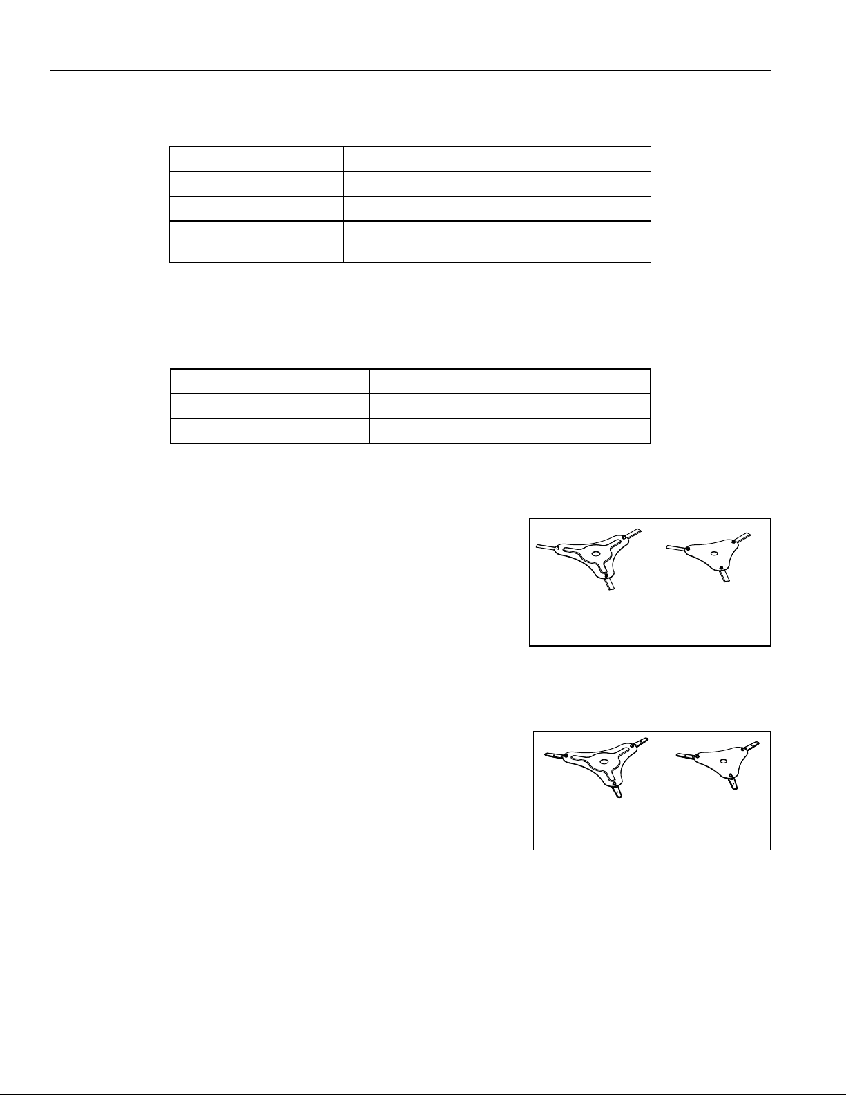
5.5 HANDLE MOUNTING HOLES ________________________________________________
The HoverKing has two mounting positions for the handle. Handle
positions are only recommendations. The handle should be
mounted so the operator has the best control of the mower based
on specific mowing conditions.
20 Inch (50.8 cm) HoverKing: The back hole is recommended for
operation on steep inclines. The front hole is recommended for
operation on more level terrain.
16 Inch (40.6 cm) HoverKing: The back hole is recommended for
operation on more level terrain. The front hole is recommended for
operation on steeper inclines.
Front Hole
Front Hole
20 inch
HoverKing
Back Hole
16 inch
HoverKing
Back Hole
5.6 BLADE DISK TORQUE______________________________________________________
Check torque on the blade disk. Do not over torque blade disk bolt or damage to the impeller bushing can result.
20 inch (50.8 cm) HoverKing - 38-40 ft. lb. (51-54 Nm)
16 inch (40.6 cm) HoverKing - 12-14 ft.lb. (16-19 Nm)
en-15

CONTROLS 6
6Controls
6.1 HANDLE CONTROLS_______________________________________________________
20 inch
HoverKing
Handle
6.1.1
6.1.2
16 inch
HoverKing
Handle
6.1.1
6.1.1 BAIL HANDLE ____________________________________________________________
The bail handle controls the operation of the OPC (Operator Presence Control) system. The bail handle must be closed
before the engine will start. When the bail handle is released, the engine must stop within 3 seconds.
6.1.2 THROTTLE LEVER (20 INCH (50.8 CM) HOVERKING ONLY) _______________________
The throttle lever is to control the engine speed. Push the throttle lever forward to increase the engine speed. Pull the
throttle lever to decrease the engine speed. When you operate the mower, Jacobsen recommends that the engine
speed is at full throttle.
When you start a cold engine, pull the throttle lever completely toward the operator to close the choke plate. Slowly
push the throttle lever forward to increase the engine speed as the engine becomes warm.
en-16

6 CONTROLS
6.2 ENGINE CONTROLS _______________________________________________________
6.2.2
6.2.5
20 inch
HoverKing
Engine
6.2.4
6.2.7
6.2.4
6.2.1
6.2.5
6.2.2
6.2.1
6.2.6
6.2.3
16 inch
HoverKing
Engine
6.2.3
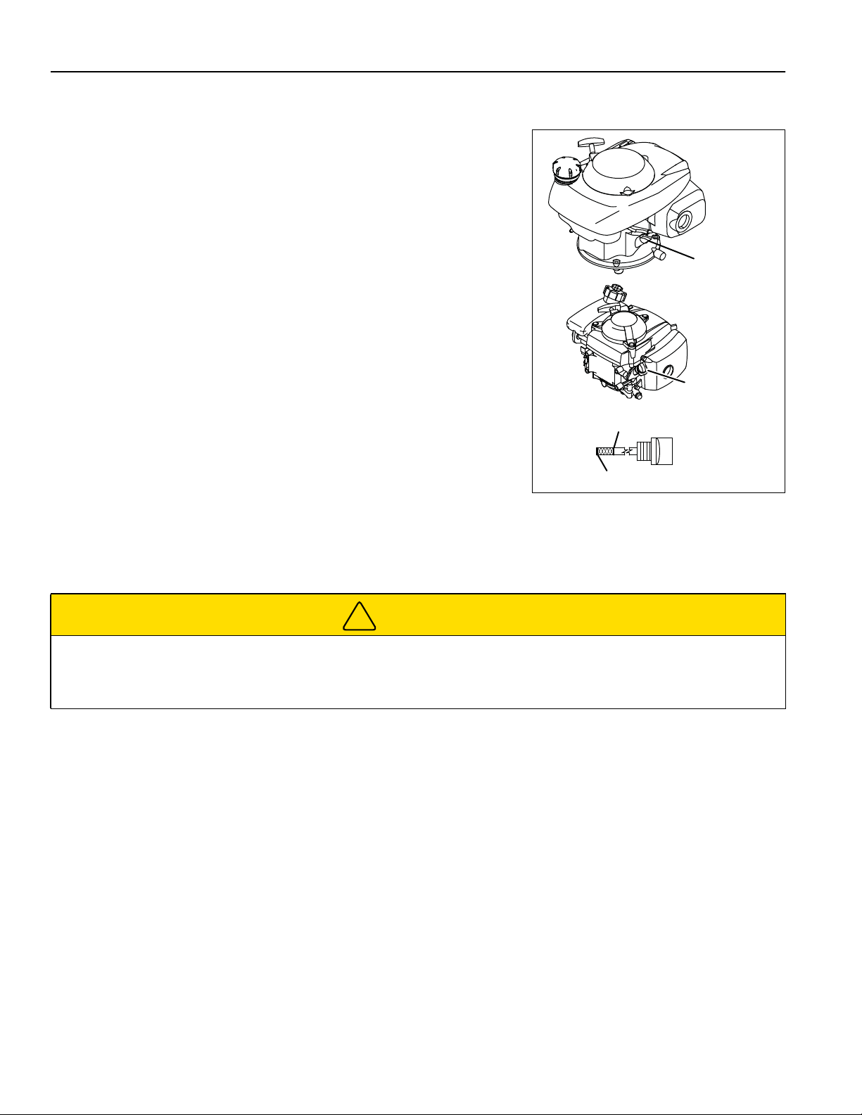
6.2.1 FUEL SHUT-OFF VALVE ____________________________________________________
Rotate the fuel shut off valve 90°to the CLOSED position to stop the flow of fuel to
the carburetor. The fuel valve must be in the OPEN position for the engine to
operate.
When the mower is not used or before you service the mower, close the fuel shut-off
valve.
OPEN
Position
CLOSED
Position
6.2.2 STARTER HANDLE ________________________________________________________
The starter handle is used to start the engine. Slowly pull on handle until resistance is felt, then pull firmly. Do not allow
the starter handle to snap back into the recoil starter.
6.2.3 DIPSTICK/OIL CAP ________________________________________________________
The dipstick/oil cap is used to check the engine crankcase oil level and add oil to the engine.
6.2.4 AIR FILTER COVER________________________________________________________
The air filter cover holds the air filter in position to prevent dirt and debris being pulled into the engine.
6.2.5 FUEL TANK CAP __________________________________________________________
Remove the fuel tank cap to add fuel to the mower. When the engine operates, do not remove the fuel tank cap. Do not
start the engine unless the fuel cap is installed.
en-17

CONTROLS 6
6.2.6 FUEL CAP BREATHER (16 INCH (40.6 CM) HOVERKING ONLY) ___________________
The fuel cap breather must be turned two to three turns to the left before you start the engine. When the mower is not
used, close the fuel cap breather.
6.2.7 CHOKE LEVER (16 INCH (40.6 CM) HOVERKING ONLY) __________________________
When you start a cold engine, move the CHOKE lever to the choke position.
Slowly push the choke lever to the RUN position as the engine becomes
warm.
RUN
Position
Choke
Position
en-18

7 OPERATION
7Operation
7.1 DAILY INSPECTION________________________________________________________
!
CAUTION
The inspection must be done each day when the engine is stopped.
Do a visual inspection of the mower. Look for indications of wear or loose hardware. Look for any damaged
components.
Check the fuel supply and crankcase oil level. When the engine is cold, all fluids must be at the full level mark.
Test the OPC system.
7.2 OPC SYSTEM_____________________________________________________________
The OPC System prevents the engine to start unless the bail handle is closed. The system stops the engine if the
operator releases the bail handle.
!
WARNING
Do not operate the equipment with the OPC System disconnected or the system does not operate correctly. Do not
disconnect or prevent the operation of any switch.
Do each of these tests to make sure the OPC System operates correctly. If any of the tests fail, stop the test and have
the system inspected and repaired as shown below:
• The engine does not start during test 1
• The engine does start during test 2
• The engine continues to run during test 3
Refer to the chart below for each test and follow the check (✔) marks across the chart. Turn off the engine between
each test.
TEST 1: The test shows the normal engine start procedure. The bail handle is closed. The engine will start.
TEST 2: The engine must not start if the bail handle is open.
TEST 3: Start the engine with the normal procedure. Release the bail handle. The engine and mower blades must
stop..
Test Bail Handle
Closed
Yes No Yes No
1 ✔✔
2 ✔✔
3 ✔★★
Engine Starts
en-19
★ Start the engine with the normal procedure,
release the bail.
The engine must stop and the cutting unit blades
must not rotate after three (3) seconds.

OPERATION 7
7.3 OPERATING PROCEDURE __________________________________________________
!
CAUTION
To prevent injury, always wear safety glasses, leather work shoes or boots, a hard hat and ear protection.
1. Never operate the engine without enough ventilation or in an enclosed area. The carbon monoxide in the exhaust
fumes can increase to dangerous levels.
2. Keep your hands and feet away from moving parts and the cutting units. When possible, do not adjust the mower
with the engine started.
3. Do not operate the mower with loose or damaged components. All components must be correctly fastened to the
mower. Mow when the grass is dry to get the best results.
4. First cut in a test area so that you completely understand the operation of the mower and controls.
5. Inspect the area to find the safest procedure for the mower. Check the height of the grass, the type of terrain and
the conditions of the surface. Each condition needs the correct adjustments and precautions.
6. Do not release the cut grass in the direction of persons or allow persons near the mower while in operation. The
owner and operator are responsible for injuries caused to persons near the mower and any damage to their
property.
!
CAUTION
Remove all objects you can find before you operate the mower. Carefully enter a new area and always operate at
speeds that allow you to control the mower safely.
7. Be careful when you operate near to gravel areas (roads, parking areas, cart paths). Stones released from the
equipment can cause injuries to persons and cause damage to the equipment.
8. When you are not mowing grass, always stop the engine.
9. When you hit an object or mower starts to cause vibration that is not normal, inspect the mower for damage and
make repairs.
!
WARNING
Before you clean, adjust or repair this equipment, always stop the engine, close the fuel shut-off valve and
disconnect the spark plug wire..
10. Walk slowly and be careful when you operate on the slopes or near sharp edges.
11. Never use your hands to clean the blades. Use a brush to remove the grass clippings from the blades. The
blades are sharp and can cause injuries.
en-20

7 OPERATION
7.4 STARTING THE ENGINE ____________________________________________________
20 Inch (50.8 cm) HoverKing:
Start the engine with the operator behind or on the right side of the mower.
Check the engine oil level.
Check fuel level. Make sure fuel shut-off valve is in the OPEN position
When you start a cold engine, pull the throttle lever completely toward the
operator to close the choke plate.
Pull and hold the bail handle against the upper handle. Move the handle to
the upright position.
Place your foot firmly on the rear surface of the deck.
Slowly pull on the starter handle until resistance is felt, then pull firmly. Do
not allow the starter handle to snap back into the recoil starter. Repeat
until the engine starts.
When the engine starts, slowly push the throttle lever forward to increase
the engine speed as the engine becomes warm.
16 Inch (50.8 cm) HoverKing:
Bail
Handle
Throttle
Lever
Starter
Handle
Fuel Shut-Off
Valve
Start the engine with the operator behind or on the right side of the
mower.
Check the engine oil level.
Check fuel level. Make sure fuel shut-off valve is in the OPEN
position. Turn the fuel cap breather two to three turns to the left.
When you start a cold engine, move the choke lever to the CHOKE
position.
Pull and hold the bail handle against the upper handle. Move the
handle to the upright position.
Place your foot firmly on the rear surface of the deck.
Slowly pull on the starter handle until resistance is felt, then pull firmly.
Do not allow the starter handle to snap back into the recoil starter.
Repeat until the engine starts.
When the engine starts, slowly move the choke lever to the RUN
position as the engine becomes warm.
Fuel Cap
Breather
Choke
Lever
Bail
Handle
Starter
Handle
Fuel Shut-Off
Valve
en-21

OPERATION 7
7.5 TO STOP THE ENGINE ______________________________________________________
1. Release the bail lever to stop the engine. Allow the engine to settle to the ground and all movement stop.
2. Move the fuel shut-off valve to the closed position.
3. 16 inch (40.6 cm) HoverKing: Close the fuel cap breather valve.
7.6 MOWING_________________________________________________________________________
!
WARNING
To prevent injuries, when the blades rotate, keep your hands, feet and clothing away from the cutting unit.
NEVER use your hands to clean the cutting units. Use a brush to remove grass from the blades. The blades can be
sharp and can cause injury.
Only mow when the grass is dry.
Make sure of your footing when you operate on slopes. Operation on slopes needs caution. If you are not
comfortable when you operate on a slope, do not mow the slope.
Always stay above the mower when you mow on slopes. Keep the mower pointing down when you mow on slopes.
Never mow by pushing the hover mower up a slope.
Mow across slopes horizontally, not vertically.
To m o w:
1. Move the mower to the area to be mowed. Start the engine.
2. To get the best results and highest quality of cut, start at the outer edge of the area to be mowed. Mow from the
left side to the right side in decreasing sized half circles starting at the edge of your turf and work inwards. When
you follow this pattern, the mulching performance of the mower improves.
3. Do not cut off more than 1/3 of the length of the blade of grass. Cutting more than 1/3 of the blade length can
damage the health of your turf. Hover mowers do an excellent job mowing grass over mixed surfaces, make sure
that the surfaces are level to each other and are free from branches, rocks and debris.
4. You can trim around the trees and bushes in half circle motions.
5. Use caution and be aware of your footing when you operate the mower on slopes. Move the hover mower from
the right to the left side along the slope. Stand at the top of the hill. Start at the bottom of the slope and work your
way to the top. When you must mow on steep or deep slopes, use the handle extension kit for easy and safe
operation.
Always stay above the mower when you mow on slopes.
6. To mow around sand trap and flower bed edges: Walk forward while you pull the hover mower towards you in a
clockwise direction around the edge. Mow from the left side to the right side so that the rotation of the blades
throws any grass or debris away from the bed or sand trap. The hover mower deck must never be more than 3 to
4 inches (7.5 to 10 cm) over the edge of the bed or sand trap edge.
7. To trim around surface transitions: When the turf is the same level as the path, move the hover mower slowly
towards the grass edge, the airflow will raise the overhanging grass and it will create a neat and quality cut
.
en-22

8 MAINTENANCE AND LUBRICATION CHARTS
8Maintenanceand Lubrication Charts
8.1 MAINTENANCE CHART
Mower Service Interval Chart
Interval Item Section
First 5 Hours
or First Month
1
• Replace the engine oil
• Check all blades and blade bolts.
• Check engine shaft bolt and blade disk
Each day • Check OPC System
• Check the engine oil level
• Check the air filter
• Check the blades, blade bolts and blade disk for damage or
loose hardware
• Clean any grass or dirt from blades and mower housing.
• Make sure air inlet around engine base is not blocked.
• Inspect the mower for hardware that is loose or missing.
• Inspect the mower for damage.
Each 25 hours
or 3 Months
1
Each 50 Hours
or 6 Months
1
Each 100 Hours
or Year
1
Each 200 Hours
or 2 Years
1
Whichever occurs first. Log hours of operation to determine proper maintenance intervals.
1
• Clean the air filter
• Replace the engine oil
• Check the spark plug. Replace if needed.
• Replace spark plug
• Replace air filter
2
3
2
Clean the air filter more often when used in dusty areas.
3
Change engine oil every 25 hours when used under heavy load or in high ambient temperatures.
en-23

MAINTENANCE 9
9Maintenance
9.1 GENERAL PRECAUTIONS ________________________________________________________
!
WARNING
Before you clean, adjust or repair this equipment, stop the engine, close the fuel shut-off valve and disconnect the
spark plug wire.
Make sure the mower is parked on a solid and level surface. Only tilt the mower so the air cleaner and carburetor
are above the crankcase.
A qualified technician must always do adjustments and maintenance. If the correct adjustments can not be made,
contact your Jacobsen Dealer.
Inspect the equipment according to the maintenance schedule and keep complete records.
a Keep the equipment clean.
b Keep all moving parts correctly adjusted and lubricated.
c Replace worn or damaged parts before you operate the mower.
d Keep all fluids at the correct level.
When you make the adjustments or repairs, do not wear jewelry or loose fitting clothing.
Refer to the illustrations in the Parts Manual for the removal and assembly of parts.
When you discard hazardous materials (engine oil, fuel), follow your local, state or federal-recommended procedures.
9.2 ENGINE __________________________________________________________________
IMPORTANT - The mower includes a separate Engine Manual prepared by the engine manufacturer. Read the Engine
Manual and know the operation and maintenance of the engine. When you follow the engine manufacturer instructions,
you will make sure of the maximum service life of the engine. The replacement engine manuals are available from the
engine manufacturer.
Refer to the Engine Manual as an aid when you check or change the oil or service the air cleaner.
The operation and maintenance during the first 5 hours of a new engine can make a difference to the performance and
life of the engine.
During the first 5 hours of operation, Jacobsen recommends the following.
• Allow the engine to reach a temperature of at least 140° F (60° C) before operation at full load.
• Check the engine oil level two times each day. Higher than normal oil use can occur during the first 5 hours.
• Change the engine oil and oil filter after the first 5 hours of operation.
• Check the air filter.
• Refer to the Engine manual for specified maintenance intervals.
NOTICE
The mower operates and cuts correctly at the preset governor setting. Do not change the engine governor setting
or over speed the engine.
en-24
9 MAINTENANCE
9.3 ENGINE OIL ______________________________________________________________
Check engine oil level
Check the engine oil level before you start the engine or at least five minutes
after you stop the engine.
a Place the mower on a level surface.
b Remove the oil cap and dipstick. Clean the dipstick with a clean cloth.
c Insert the dipstick until the cap touches the engine base. Do not screw
the cap into the engine.
d Remove the dipstick. Engine oil must be between the upper and lower
level marks.
e If the engine oil level is above the upper level mark, remove the excess
engine oil.
f If the engine oil level is below the lower limit mark, add more engine
oil. Check the oil level again. Do not overfill the engine.
Change Engine Oil
a Start the engine to increase the temperature, then stop the engine.
Turn the fuel shut-off valve to the CLOSED position and disconnect
the spark plug wire.
b Remove the drain plug from the bottom of the crankcase and clean with a cloth.
c Drain the engine oil into a container.
20 inch
HoverKing
Engine
Oil cap and
dipstick
16 inch
HoverKing
Engine
Oil cap and
dipstick
Upper Limit Mark
Lower Limit Mark
d Replace the drain plug and fill the engine with the correct quantity and grade of oil through the filler.
!
CAUTION
The engine oil can damage your skin. Use gloves when you use engine oil. If engine oil touches your skin, clean the
area immediately.
Discard used engine oil as shown in local regulations.
9.4 ENGINE AIR FILTER _______________________________________________________
Clean the outside of the filter cover. Remove the cover and the air filter.
Clean the inside of the filter housing and cover. Make sure dust and other particles do not get into the carburetor inlet.
20 inch (50.8 cm) HoverKing: Tap the filter several times on a hard surface to remove dirt. Never try to brush off dirt.
16 inch (40.6 cm) HoverKing: Clean the filter in warm soapy water. Rinse and allow to dry completely. Dip the filter in
clean engine oil. Squeeze out all excess oil. When started, the engine will smoke if too much oil is left in the filter.
When you replace the filter, inspect the new filter. Do not use a damaged filter and never use an incorrect filter.
Assemble the filter and cover to the filter housing.
en-25

MAINTENANCE 9
9.5 FUEL ____________________________________________________________________
Gasoline is flammable. Use caution when you add the fuel to the mower. Only use an approved container. The
spout on the container must fit inside the fuel filler neck. Never use the containers that are not approved to keep or
transfer fuel.
!
WARNING
Refuel the mower before you start the engine. When the engine is in operation or while the engine is hot, never
remove the fuel cap or add fuel to the mower.
Refuel outdoors only and do not smoke when you add fuel.
If the fuel spills, do not try to start the engine, but move the mower away from the area. Until fuel vapors are
removed, do not allow the sparks, open flame or other types of ignition.
Never keep fuel containers near an open flame or any device that can cause the ignition of fuel or fuel vapors.
Always tighten the fuel tank cap and container cap after you add fuel.
Fill the fuel tank to less than 1 inch (2.5 cm) below the filler neck.
Use clean unleaded gasoline with a 87 octane rating minimum.
Check fuel hoses and clamps each year. Replace fuel hoses and clamps at first indication of wear or damage.
Keep fuel according to your local, state or federal regulations and instructions from your fuel supplier.
9.6 ENGINE EXHAUST _______________________________________________________________
!
WARNING
The exhaust fumes contain carbon monoxide. The carbon monoxide in the exhaust fumes can increase to
dangerous levels. To protect you from carbon monoxide poisoning, inspect the complete exhaust system every
month and replace damaged components immediately.
NEVER operate the engine without enough ventilation.
The temperature of the exhaust components can be greater than 300° F (149° C). To prevent the burns, do not
touch a hot exhaust system.
If you sense a change in the color or sound of the exhaust, stop the engine immediately. Identify the problem and have
the system repaired.
en-26

9 MAINTENANCE
9.7 INSPECTING CUTTER DISK _________________________________________________
A bent or unbalanced cutter disc can cause excessive vibration. Always mow with a flat and balanced cutter disc and
non worn blades. Make sure that the cutter disc insert nuts, blade bolts and blades are properly securely fastened to
the disc.
1. Stop the engine and wait for all moving parts to stop. Turn the fuel shut-off valve to the closed position and
disconnect the wire from the spark plug.
2. Rotate and tip the lawn mower onto its left edge with the carburetor and air cleaner facing up and away from the
ground.
3. Remove the blade attachment bolts and the blades.
4. Remove the engine shaft bolt and washer.
5. Remove blade disc from the mower and place on a flat level surface with the blade side facing down.
6. Inspect for a consistent gap at each of the three blade disc ends where blades are attached.
7. If an inconsistent gap is seen between the flat surface and the surface of the blade disc, or if the disc is warped or
damaged in any way, replace the blade disc.
!
WARNING
Never operate the mower with a bent or damaged blade disc. A bent or damaged disc will cause excessive vibration
and unsafe operating conditions including loose components or thrown objects. Loose components can be thrown
causing serious injury or death.
8. Inspect the disc insert nuts to ensure they are properly secure and tight. If the insert nuts are loose or damaged,
the blade disk must be replaced. Do not attempt to tighten the insert nuts if they are loose.
9. Inspect the blade attachment bolts for excessive wear and to ensure they are properly tightened. Make sure the
correct blade bolts are used. Using incorrect blade bolts can result in injury or death. The blade bolts used with
the metal blades are black in color. The blade bolts used with the plastic blades are silver in color. Never use
incorrect blade bolts.
10. Tighten, blade bolts to 7 ft. lb. (9.5 Nm). Replace worn or damaged bolts. Loose or damaged bolts can cause
blades or blade bolts to be thrown into the operator mowing area causing serious injury or death.
11. Inspect the blades for wear or damage. Replace worn and damaged blades immediately. Worn or damaged
blades can cause objects be thrown into operator mowing area causing serious injury or death.
!
WARNING
Always replace all three blades at the same time. Never replace only one or two blades. When you replace less than
all three blades at the same time can cause your mower to become unbalanced and can cause excessive vibration.
Excessive vibration can create unsafe operating conditions resulting in loose or thrown objects which can result in
serious injury or death.
en-27

MAINTENANCE 9
9.8 CARE AND CLEANING _____________________________________________________
Clean the mower after each use. To prevent damage to the engine, do not wash the mower with the engine in
operation. When possible, clean the mower with compressed air.
NOTICE
Do not wash any part of the mower that is hot. Do not use the high-pressure spray or steam. Use cold water and
automotive cleaners.
!
WARNING
Never use your hands to clean the blades. Use a brush to remove grass clippings from the blades. The blades are
sharp and can cause injuries.
Keep the top and bottom of the deck housing clean and free of grass and debris. Never block the impeller air intake
openings around the base of the engine. Tilt the mower on the left edge so the air filter and carburetor face up and
away from the ground to clean the bottom of the deck housing.
Use compressed air to clean the engine. Do not pressure wash engine.
Use clean water to wash your equipment.
NOTICE
To use salt water or drain water is known to cause rust and corrosion of metal parts and can cause damage or
failure. This damage is not included by the factory warranty.
Clean all plastic or rubber parts with a weak soap solution or use commercially available rubber cleaners.
Repair damaged metal surfaces and use Jacobsen touch-up paint. Apply wax to the equipment for maximum paint
protection.
!
CAUTION
To prevent fire, clean grass clippings and dirt from the cutting disk, engine and exhaust components.
en-28

9 MAINTENANCE
9.9 MOWER STORAGE ________________________________________________________
General
• Clean the mower. Repair and paint damaged or exposed metal.
• Inspect the mower, tighten all hardware, replace worn or damaged components.
• Keep the mower and all accessories clean, dry and protected from the elements. Never keep the mower near an
open flame or spark which can cause ignition of the fuel or fuel vapors.
Engine
• Drain the fuel from the mower. Start the engine. Allow the engine to operate until it runs of fuel and stops. Try to
start the engine again. When you can no longer start the engine, the fuel system is completely empty.
• While the engine is warm, remove the drain plug and drain the oil from the crankcase. Install the drain plug and
fill the engine with oil.
• Remove the spark plug and add 1 ounce (29 ml) of clean engine oil into the spark plug hole. Slowly pull the
starter rope several times to distribute the engine oil on the cylinder walls. Install the spark plug.
• Clean the outside surface of the engine. Paint bare metal or apply a thin layer of rust preventative oil.
Blades
• Completely clean the blade disk and blades. Paint any damaged or bare metal surfaces.
• Apply a thin layer of rust preventative oil to the sharpened edges of the blades.
!
CAUTION
The blades have sharp edges. To prevent injury, use caution when you service or hold the blade.
After Storage
• Remove the spark plug. Place a clean rag over the spark plug hole and pull the starter handle quickly to remove
excess oil from the cylinder. Install the spark plug.
• Check or service the air filter
• Check the level of engine oil.
• Fill the fuel tank with fuel.
• Remove all oil from the blades. Adjust the cutting height.
• Start the engine and allow the engine to become warm and lubricated.
!
WARNING
Never operate the engine without enough ventilation or in an enclosed area. The carbon monoxide in the exhaust
fumes can increase to dangerous levels.
en-29

ADJUSTMENTS 10
10Adjustments
10.1 GENERAL PRECAUTIONS ________________________________________________________
!
WARNING
Before you clean, adjust or repair this equipment, stop the engine, close the fuel shut-off valve and disconnect the
spark plug wire.
Make sure the mower is parked on a solid and level surface. Only tilt the mower so the air cleaner and carburetor
are above the crankcase.
A qualified technician must always do adjustments and maintenance. If the correct adjustments can not be made,
contact your Jacobsen Dealer.
Inspect the equipment according to the maintenance schedule and keep complete records.
a Keep the equipment clean.
b Keep all moving parts correctly adjusted and lubricated.
c Replace worn or damaged parts before you operate the mower.
d Keep all fluids at the correct level.
When you make the adjustments or repairs, do not wear jewelry or loose fitting clothing.
Refer to the illustrations in the Parts Manual for the removal and assembly of parts.
When you discard hazardous materials (engine oil, fuel), follow your local, state or federal-recommended procedures.
10.2 HEIGHT OF CUT (HOC) _____________________________________________________
The height of cut is adjusted by adding or removing 1/2 inch (1.2 cm)
spacers between the blade disk and the impeller.
1. Stop the engine, close the fuel shut-off valve and disconnect the
spark plug wire.
2. Tilt the mower on the left edge so the air filter and carburetor face
up and away from the ground to access the bottom of the deck
housing.
3. Remove the engine shaft bolt, washer and blade disk.
!
CAUTION
The blades have sharp edges. To prevent injury, use caution when
you service or hold the blade.
4. Refer to the height of cut chart and install the correct number of spacers between the blade disk and the impeller.
5. Using the correct length engine shaft bolt for the height of cut, assemble the blade disk, washer and engine shaft
bolt. Tighten the shaft bolt to 38-40 ft. lb. (51-54 Nm) for the 20 inch (50.8 cm) HoverKing or 12-14 ft.lb. (16-19
Nm) for the 16 inch (40.6 cm) HoverKing.
6. Store remaining engine shaft bolt lengths and spacers for future use.
HOC Spacers
3 inch (7.6 cm) 0 3/8-24 x 3-1/2 inch (8.9 cm) 1/4-28 x 2-3/4 inch (7 cm)
2-1/2 inch (6.4 cm) 1 3/8-24 x 3-1/2 inch (8.9 cm) 1/4-28 x 3-1/4 inch (8.3 cm)
2 inch (51 cm) 2 3/8-24 x 4-1/2 inch (11.4 cm) 1/4-28 x 3-3/4 inch (9.5 cm)
1-1/2 inch (3.8 cm) 3 3/8-24 x 4-1/2 inch (11.4 cm) 1/4-28 x 4-1/4 inch (10.8 cm)
1 inch (2.5 cm) 4 3/8-24 x 4-1/2 inch (11.4 cm) 1/4-28 x 4-3/4 inch (12.1 cm)
Engine Shaft Bolt
20 inch (50.8 cm) HoverKing
Blade Disk
Washer
Engine Shaft Bolt
16 inch (40.6 cm) HoverKing
Spacer(s)
Shaft Bolt
en-30

10 ADJUSTMENTS
10.3 BAIL CABLE ADJUSTMENT (20 INCH MOWERS) _______________________________
Adjust the bail cable to remove excess movement.
Make sure the bail cable is inserted in the correct slot in the throttle
lever.
• When the standard handle is installed, the bail cable must be
in the upper slot.
• When the optional tapered handle is installed, the bail cable
must be in the lower slot.
Use the cable adjuster as required to adjust the cable length.
Test the operation of the OPC handle.
Upper Slot
Lower Slot
• When the bail is open, the engine must not start.
• When the bail is closed, the engine will start.
• When the bail is released, the engine must stop.
Cable
Adjuster
en-31

ADJUSTMENTS 10
10.4 TORQUE SPECIFICATION ___________________________________________________
NOTICE
The torque values included in these charts are approximate and are for reference only. Use these torque values at
your risk. Jacobsen is not responsible for any loss, claim or damage caused by these charts. Always use caution
with torque values.
Jacobsen uses Grade 5 (Inch) and Grade 8.8 (Metric) Plated bolts, unless a note is given. Always check the marks on
the head of the bolts for the bolt grade. For tightening plated bolts, use the value given for lubricated.
AMERICAN NATIONAL STANDARD FASTENERS
SIZE UNITS
SIZE UNITS
GRADE 5 GRADE 8
Lubricated Dry Lubricated Dry Lubri-
#6-32 in-lb (Nm) – 20 (2.3) – – 7/16-14 ft-lb (Nm) 37 (50.1) 50 (67.8) 53 (71.8) 70 (94.9)
#8-32 in-lb (Nm) – 24 (2.7) – 30 (3.4) 7/16-20 ft-lb (Nm) 42 (56.9) 55 (74.6) 59 (80.0) 78 (105)
#10-24 in-lb (Nm) – 35 (4.0) – 45 (5.1) 1/2-13 ft-lb (Nm) 57 (77.2) 75 (101) 80 (108) 107 (145)
#10-32 in-lb (Nm) – 40 (4.5) – 50 (5.7) 1/2-20 ft-lb (Nm) 64 (86.7) 85 (115) 90 (122) 120 (162)
#12-24 in-lb (Nm) – 50 (5.7) – 65 (7.3) 9/16-12 ft-lb (Nm) 82 (111) 109 (148) 115 (156) 154 (209)
1/4-20 in-lb (Nm) 75 (8.4) 100 (11.3) 107 (12.1) 143 (16.1) 9/16-18 ft-lb (Nm) 92 (124) 122 (165) 129 (174) 172 (233)
1/4-28 in-lb (Nm) 85 (9.6) 115 (13.0) 120 (13.5) 163 (18.4) 5/8-11 ft-lb (Nm) 113 (153) 151 (204) 159 (215) 211 (286)
5/16-18 in-lb (Nm) 157 (17.7) 210 (23.7) 220 (24.8) 305 (34.4) 5/8-18 ft-lb (Nm) 128 (173) 170 (230) 180 (244) 240 (325)
5/16-24 in-lb (Nm) 173 (19.5) 230 (26.0) 245 (27.6) 325 (36.7) 3/4-10 ft-lb (Nm) 200 (271) 266 (360) 282 (382) 376 (509)
3/8-16 ft-lb (Nm) 23 (31.1) 31 (42.0) 32 (43.3) 44 (59.6) 3/4-16 ft-lb (Nm) 223 (302) 298 404 315 (427) 420 (569)
3/8-24 ft-lb (Nm) 26 (35.2) 35 (47.4) 37 (50.1) 50 (67.8) 7/8-14 ft-lb (Nm) 355 (481) 473 (641) 500 (678) 668 (905)
METRIC FASTENERS
SIZE UNITS Non Critical
4.6 8.8 10.9 12.9
Lubricated Dry Lubricated Dry Lubricated Dry Lubricated Dry
M4 Nm (in-lb) ––––––3.83 (34) 5.11 (45) 2.0 (18)
M5 Nm (in-lb) 1.80 (16) 2.40 (21) 4.63 (41) 6.18 (54) 6.63 (59) 8.84 (78) 7.75 (68) 10.3 (910 4.0 (35)
M6 Nm (in-lb) 3.05 (27) 4.07 (36) 7.87 (69) 10.5 (93) 11.3 (102) 15.0 (133) 13.2 (117) 17.6 (156) 6.8 (60)
M8 Nm (in-lb) 7.41 (65) 9.98 (88) 19.1 (69) 25.5 (226) 27.3 (241) 36.5 (323) 32.0 (283) 42.6 (377) 17.0 (150)
M10 Nm (ft-lb) 14.7 (11) 19.6 (14) 37.8 (29) 50.5 (37) 54.1 (40) 72.2 (53) 63.3 (46) 84.4 (62) 33.9 (25)
M12 Nm (ft-lb) 25.6 (19) 34.1 (25) 66.0 (48) 88.0 (65) 94.5 (70) 125 (92) 110 (81) 147 (108) 61.0 (45)
M14 Nm (ft-lb) 40.8 (30) 54.3 (40) 105 (77) 140 (103) 150 (110) 200 (147) 175 (129) 234 (172) 94.9 (70)
GRADE 5 GRADE 8
Dry Lubri-
cated
cated
Dry
Fasteners into
Aluminum
en-32

11 PROBLEM SOLVING
11ProblemSolving
11.1 GENERAL________________________________________________________________
The problem solution chart lists basic problems that can occur during start and operation of the mower. For complete
information about the hydraulic and electrical systems, contact your Jacobsen Dealer.
Symptoms Possible Causes Action
Engine will not
start.
Engine hard to
start or looses
power.
Engine runs
poorly.
1. Spark plug wire is
disconnected.
2. The fuel cap breather hole
is plugged.
3. The air filter is dirty. 3. Clean or replace the air filter.
4. Air filter is soaked in
gasoline.
5. The spark plug gap is
incorrect.
6. The spark plug is pitted,
fouled or cracked
7. The fuel tank is empty Fuel
stale or dirty.
8. OPC System is not
functioning.
9. Throttle or choke lever not
in the CHOKE position
1. Fuel level low, fuel stale or
dirty.
2. Air filter dirty. 2. Clean or replace the air filter.
3. The fuel cap breather hole
is plugged.
4. Deck housing plugged with
grass clippings. Impeller air
intake blocked.
5. Engine oil too low, too high
or dirty.
6. Engine problem. 6. Consult engine manual.
1. Spark plug wire not full
connected to sprak plug
2. The spark plug gap is
incorrect.
3. The spark plug is pitted,
fouled or cracked
4. Air filter dirty. 4. Clean or replace the air filter.
5. Throttle or choke lever in
the CHOKE position.
1. Connect the spark plug wire.
2. Clean the fuel cap breather hole or replace the fuel cap.
4. Replace the air filter. Only tip the mower on the left side so
the air filter and carburetor is away from the ground.
5. Check the spark plug and adjust the gap.
6. Replace the spark plug
7. Drain and refill fuel tank with fresh gasoline.
8. Test, adjust, or repair OPC System.
9. Move throttle or choke lever to CHOKE position.
1. Fill with fresh fuel.
3. Clean the fuel cap breather hole or replace the fuel cap.
4. Remove grass clippings or dirt from bottom of deck
housing and impeller air intake around engine base.
5. Add or remove oil until the correct oil level is achieved.
Replace dirty engine oil.
1. Fully press the spark plug wire onto the spark plug.
2. Check the spark plug and adjust the gap.
3. Replace the spark plug
5. Move the throttle or choke lever to the RUN position.
en-33

Symptoms Possible Causes Action
The mower or
engine vibrates
more than normal.
1. The bottom of the deck
housing contains grass or
debris
2. The engine mounting bolts
are loose
3. Engine mount to deck
hardware is loose.
4. The blade bolts are loose
or missing.
5. The blade disk is bent or
warped.
6. One or more blades
missing.
7. A blade is bent or broken. 7. Install three new blades.
8. HOC spacers not installed
correctly.
9. Blade disk not properly
seated on impeller hub or
HOC spacer
10. Engine shaft bolt is loose. 10. Tighten the engine shaft bolt to 38 ft. lb. (51.5 Nm)
1. Clean bottom of deck housing.
2. Tighten the engine mounting bolts.
3. Tighten engine mount to deck hardware.
4. Tighten or replace all three blade bolts.
5. Replace the blade disk.
6. Install three new blades.
8. Remove and install HOC spacers properly.
9. Install blade disk so it properly seats on the hub or HOC
spacers.
PROBLEM SOLVING 11
en-34

12 NOTES
12Notes
en-35

PARTS LIST 13
13PartsList
13.1 HOW TO USE THE PARTS CATALOG__________________________________________
Abbreviations
N/S - Not serviced separately, can only be obtained by ordering main component or kit.
AR -Variable quantity or measurement is required to obtain correct adjustment.
Symbols such as ●, next to the item number, indicate that a note exists which contain additional information
important in ordering that part.
Indented Items
Indented items indicate component parts that are included as part of an assembly or another component. These parts
can be ordered separately or as part of the main component.
Item Part No. Qty Description Serial Numbers/Notes
● 1 123456 1 Mount, Valve Indicates a piece part
2 789012 1 Valve, Lift Includes Items 2 and 3
3 345678 1 • Handle Serviced part included with Item 2
4 N/S 1 • Seal Kit Non serviced part included with Item 2
5 901234 1 Screw, 1/4-20 x 2” Hex Head
13.2 TO ORDER PARTS _________________________________________________________
1. Write your full name and complete address on the order.
2. Explain where and how to make shipment.
3. Give product number, name and serial number that is stamped on the name plate or serial plate of your product.
4. Order by the quantity desired, the part number, and description of the part as given in the parts list.
5. Send or bring the order to an authorized Jacobsen Distributor.
6. Inspect all shipments on receipt. If any parts are damaged or missing, file a claim with the carrier before accepting.
7. Do not return material without a letter of explanation, listing the parts being returned. Transportation charges must
be prepaid.
13.3 PARTS CATALOG TABLE OF CONTENTS______________________________________
1.1.............................. 20 Inch HoverKing Handle........................................................................................................................... 37
2.1.............................. 16 Inch HoverKing Handle........................................................................................................................... 38
3.1.............................. 20 Inch HoverKing Deck Housing............................................................................................................... 39
4.1.............................. 16 Inch HoverKing Deck Housing............................................................................................................... 41
5.1.............................. Accessories .................................................................................................................................................. 43
en-36

HOVERKING
1.1 20 Inch HoverKing Handle
20 Inch (50.8 cm) HoverKing Mowers
Serial No. 32251 - All
7
8
1
5
3
4
4
6
3
9
10
10
Item Part No. Qty. Description Serial Numbers/Notes
1
2 4325129 1 Lower Handle
3 4325111 4 Carriage Bolt, 5/16-18 x 1-1/2”
4 4325123 4 Nut, 5/16-18 Nylon Insert Flange
5 4325122 1 Cable, Bail
6 4325121 1 Throttle Lever
7 4325110 1 Screw, 1/4-20 x 2-3/4” Hex Socket Stainless Steel
8 4325109 1 Nut, 1/4-20 Hex
9 4325119 2 Clevis Pin, 3/8 x 1-3/4”
10 4325147 2 Hair Pin
4325158 1 Upper Handle Includes Grip and Bail Handle
4325130 1 • Handle, Bail
2
9
37
> Change from previous revision

2.1 16 Inch HoverKing Handle
16 Inch (40.6 cm) HoverKing Mowers
HOVERKING
Serial No. 32257 - All
6
5
1
3
3
2
4
7
8
8
Item Part No. Qty. Description Serial Numbers/Notes
1
2 4325142 1 Lower Handle
3 4325111 4 Carriage Bolt, 5/16-18 x 1-1/2”
4 4325123 4 Nut, 5/16-18 Nylon Insert Flange
5 4325161 1 OPC Switch and Harness
6 4325108 1 Screw, 1/4-20 x 1-1/2” Hex Socket
7 4325119 2 Clevis Pin, 3/8 x 1-3/4”
8 4325147 2 Hair Pin
4325137 1 Upper Handle Includes Grip and Bail Handle
4325136 1 • Handle, Bail
4
7
> Change from previous revision
38

HOVERKING
3.1 20 Inch HoverKing Deck Housing
20 Inch (50.8 cm) HoverKing Mowers
Serial No. 32251 - All
14
15
™
HOVERKING
5
3
4
6
1
2
39
20
10
16 / 19
21
7
17
18
11
13
8
12
9
18
17
18
7
22
23
17
23
20
21
20
21

HOVERKING
Item Part No. Qty. Description Serial Numbers/Notes
1
2 4325113 1 • Decal, Banner Warning
3 4325114 1 • Decal, Blade Warning
4 4325115 1 Mount, Engine
5 N/S 1 Engine, Honda GCV160
6 4325112 4 Bolt, 3/8-16 x 1-1/8” Tri-Lobe
7 4325123 8 Nut, 5/16-18 Nylon Insert Flange
8 4325125 1 Key, 3/16” Square
9 4325120 1 Spacer, Impeller
10 4325124 1 Fan, Impeller
11 4325134 4 Spacer, HOC
12 4325152 1 Screw, 3/8-24 x 3-1/2” Grade 8 Used for 3-1/2” and 4” HOC
12 4325153 1 Screw, 3/8-24 x 4-1/2” Grade 8 Used for 2”, 2-1/2” and 3” HOC
13 4325118 1 Washer, Disk
14 4325155 1 Decal, HoverKing
15 4325156 1 Decal, Jacobsen
4325157 1 Deck, 20”
16 32252 1 20” Metal Blade Kit
17 4325116 3 • Blade, 4” Metal Package of 3 Blades
18 4325117 3 • Bolt, Blade Black Color
19 32253 1 20” Plastic Blade Kit
20 4325135 3 • Blade, 4” Plastic Package of 6 Blades
21 4325126 3 • Bolt, Blade Silver Color
22 32254 1 20” String Cutter Kit
23 4325146 2 • Cutter String Package of 50 Cutter Strings
> Change from previous revision
40

HOVERKING
4.1 16 Inch HoverKing Deck Housing
16 Inch (40.6 cm) HoverKing Mowers
Serial No. 32257 - All
14
5
15
™
4
HOVERKING
3
6
1
2
7
9
8
7
41
20
21
10
20
21
17
18
15
18
13
12
11
16 / 19
17
18
22
23
23
20
21

HOVERKING
Item Part No. Qty. Description Serial Numbers/Notes
1
2 4325113 1 • Decal, Banner Warning
3 4325114 1 • Decal, Blade Warning
4 4325138 1 Mount, Engine
5 N/S 1 Engine, Honda GXV57
6 4325144 4 Screw, M6-1 x 20 mm Hex Head
7 4325109 8 Nut, 1/4-20 Nylon Insert Flange
8 4325140 1 Key, 5 mm Square
9 4325145 1 Spacer, Impeller
10 4325139 1 Fan, Impeller
11 4325143 4 Spacer, HOC
12 4325151 1 Screw, 1/4-28 x 4-3/4” Grade 8 Used for 2” HOC
12 4325150 Screw, 1/4-28 x 4-1/4” Grade 8 Used for 2-1/2” HOC
12 4325149 Screw, 1/4-28 x 3-3/4” Grade 8 Used for 3” HOC
12 4325154 Screw, 1/4-28 x 3-1/4” Grade 8 Used for 3-1/2” HOC
12 4325141 Screw, 1/4-28 x 2-3/4” Grade 8 Used for 4” HOC
13 4325148 1 Washer, Disk
14 4325155 1 Decal, HoverKing
15 4325156 1 Decal, Jacobsen
4325160 1 Deck, 16”
16 32258 1 16” Metal Blade Kit
17 4325116 3 • Blade, 4” Metal Package of 3 Blades
18 4325117 3 • Bolt, Blade Black Color
19 32259 1 16” Plastic Blade Kit
20 4325135 3 • Blade, 4” Plastic Package of 6 Blades
21 4325126 3 • Bolt, Blade Silver Color
22 32260 1 16” String Cutter Kit
23 4325146 2 • Cutter String Package of 50 Cutter Strings
> Change from previous revision
42

HOVERKING
5.1 Accessories
Handle Extension Kit 20 inch Tapered Handle Kit
Serial No. All
Wheel Kit
2 / 7
5
3 / 8
1 / 6
4
11
2 / 7
9
10
43
12

HOVERKING
Item Part No. Qty. Description Serial Numbers/Notes
32255 1 20” HoverKing Handle Extension Kit
1
2 4325111 4 • Carriage Bolt, 5/16-18 x 1-1/2”
3 4325123 4 • Nut, 5/16-18 Nylon Insert Flange
4 4325127 1 • Cable, Extended Bail
5 4325128 1 • Extended Throttle Lever
6 4325132 1 • Handle Extension
7 4325111 4 • Carriage Bolt, 5/16-18 x 1-1/2”
8 4325123 4 • Nut, 5/16-18 Nylon Insert Flange
9 4325162 1 • OPC Switch w/ Extended Harness
10 4325159 1 Handle, Tapered 20 Inch (50.8 cm) HoverKing Only
11 4325133 1 • Handle, Tapered Bail 20 Inch (50.8 cm) HoverKing Only
4325132 1 • Handle Extension
32261 1 16” HoverKing Handle Extension Kit
12 32256 1 Wheel Kit
> Change from previous revision
44

INDEX
32252...........................40
32253...........................40
32254...........................40
32255...........................44
32256...........................44
32258...........................42
32259...........................42
32260...........................42
4325108.......................38
4325109.................37, 42
4325110.......................37
4325111.......... 37, 38, 44
4325112.......................40
4325113.................40, 42
4325114.................40, 42
4325115.......................40
4325116.................40, 42
4325117.................40, 42
4325118.......................40
4325119.................37, 38
4325120.......................40
4325121.......................37
4325122.......................37
4325123.... 37, 38, 40, 44
4325124.......................40
4325125.......................40
4325126.................40, 42
4325127.......................44
4325128.......................44
4325129.......................37
4325130.......................37
4325132.......................44
4325133.......................44
4325134.......................40
4325135.................40, 42
4325136.......................38
4325137.......................38
4325138.......................42
4325139.......................42
4325140.......................42
4325141.......................42
4325142.......................38
4325143.......................42
4325144.......................42
4325145.......................42
4325146.................40, 42
4325147.................37, 38
4325148.......................42
4325149.......................42
4325150.......................42
4325151.......................42
4325152.......................40
4325153.......................40
4325154.......................42
4325155.................40, 42
4325156.................40, 42
4325157...................... 40
4325158...................... 37
4325159...................... 44
4325160...................... 42
4325161...................... 38
4325162...................... 44
45

INDEX
46


Equipment from Jacobsen is built to exacting
standards ensured by ISO 9001 and ISO 14001
registration at all of our manufacturing locations.
A worldwide dealer network and factory trained
technicians backed by Genuine Jacobsen Parts
provide reliable, high-quality product support.
Jacobsen, A Textron Company
11108 Quality Drive, Charlotte, NC 28273
www.Jacobsen.com
800-848-1636
When Performance Matters.
™
 Loading...