

Page 1

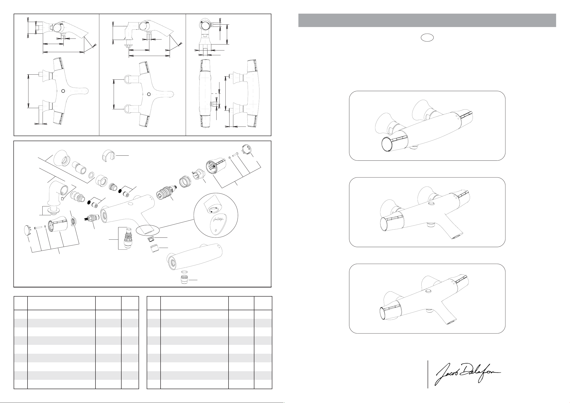
Ø59
G1/2
102 maxi
97 mini
205
G1/2
39°
70
105
208
G1/2
39°
Ø59
G1/2
G1/2
52
95 mini
100maxi
N O T I C E T E C H N I Q U E
F
SYMBOL
MITIGEUR THERMOST ATIQUE
150±15
20maxi
E71684-..
12
150
E71685-.. E71683-..
13
150±15
G1/2
20maxi
2
16
15
14
3
1
14
4
6
17
7
8
2
9
10
➛
Clé fournie
ou 1 pièce 1 euro
5
.peRnoitangiséD
1
2
3
4
5
6
7
8
9
11
edoC
elcitra
A8E
erutarépmetedeéngiopelbmesnE
ehcaC
exifeétuB
euqitatsomrehtehcuotraC
tibédedeéngiopelbmesnE
elbalgéreétuB
euqimarécseuqsidàetêT
ruesrevnielbmesnE
ruetaréa'dreinaP
PC-561
PC-361A8E
FN120A8R
93250392R
PC-461A8E
FN420A8R
50430392R
PC-751A8E
FN851A8R
.dnoC
rap
1
1
1
1
1
1
2
1
1
.peRnoitangiséD
01
11
21
31
41
51
61
71
ruetaréa'degaC
tniojcevaelliuoD
secasorederiaP
uorcé-egètorP
ruoter-itnateertlifelbmesnE
siV
settennolocederiaP
noitaxifedelbmesnE
edoC
elcitra
PC-951A8E
96972992R
PC-161A8E
FN061A8R
FN620A8R
40440392R
PC-651A8E
FN900A8R
.dnoC
rap
1
1
1
2
2
1
1
1
39007064 revision 4 1/5
Une marque de la Société KOHLER FRANCE - 330 339 144 RCS BOBIGNY
Siège Social : Immeuble Le Cap - 3, rue de Brennus
TEL. : 33 (0) 1 49 17 37 37 - FAX : 33 (0) 1 49 17 37 40
SERVICE ASSISTANCE CLIENTÈLE : 0810 307 000
93631 La Plaine St Denis cedex
www.jacobdelafon.fr
www.jacobdelafon.es
SAT ESPAÑA Y PORTUGAL : 902 11 38 36
Page 2
CONDITIONS DE FONCTIONNEMENT DU MITIGEUR THERMOSTATIQUE
Les pressions indiquées sont mesurées en écoulement (pression dynamique)
- Pressions d'alimentation mini/maxi
- Pressions d'alimentation supérieures à 5 bars
- Pressions d'alimentation recommandées
- Différence de pression
-Température d'alimentation en eau chaude, mini
-Température d'alimentation en eau chaude, maxi
- Température d'alimentation en eau chaude recommandée
-Plage de réglage, environ
-Butée de sécurité à
-Limitation de la température en tout chaud
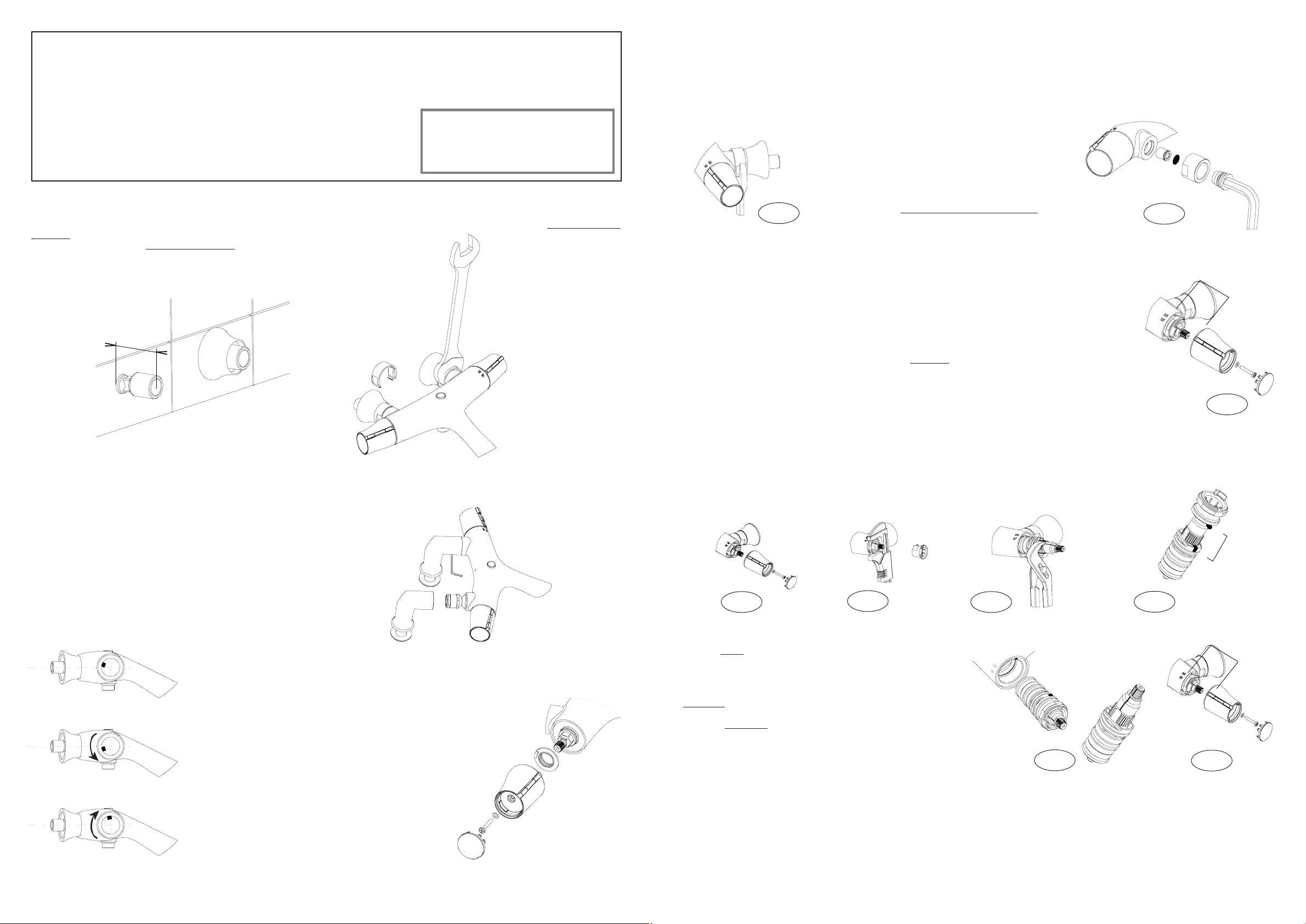
INSTALLATION
- Avant l’installation, purger soigneusement les canalisations. La robinetterie installée, démonter l’aérateur avant sa mise en eau. Ouvrir l’eau. Le
sélecteur de débit ouvert au maximum. Tourner le sélecteur de température en chaud maximum, puis en froid maximum afin d’éliminer toutes les
impuretés par un écoulement abondant. Remonter l’aérateur.
- Raccorder impérativement l'eau chaude à gauche (près de la poignée de réglage de débit).
MONTAGE DES ROBINETTERIES MURALES
: 1 bar/6 bars
: installer un réducteur de pression
: 3 bars dynamiques sur eau chaude et sur eau froide
: 2 bars maximum
: 50°C
: 80°C
: 60°C (économie d'énergie)
: 20°C à 50°C
: 40°C
: maxi 50°C
Nos mitigeurs thermostatiques fonctionnent
parfaitement avec un chauffe-eau à
accumulation. Une puissance d'au moins
18 Kw (250 mth/mn) est requise pour un
chauffe-eau instantané ou mixte.
➚
➁
40 à 45 mm
➚
➀
ENTRETIEN
Revêtement : La finition spéciale de ce mitigeur exige une attention particulière : pour conserver l’aspect de votre robinetterie, nettoyer
régulièrement sa surface avec une éponge savonneuse non abrasive, bien rincer et essuyer avec un linge doux. Eviter formellement l'utilisation des
produits contenant de l'alcool méthylique, des acides, des solvants ou des abrasifs qui endommageraient le revêtement.
Cartouche thermostatique : Avec des eaux fortement calcaires ou chargées, les filtres protégeant la cartouche thermostatique peuvent
s'obstruer et réduire le débit. Il sera alors nécessaire de nettoyer les filtres en trempant dans du vinaigre chaud la cartouche sur laquelle ils sont sertis
en suivant les indications du paragraphe de démontage de la cartouche thermostatique.
Filtres et clapets anti-retour : Les filtres protégeant la robinetterie peuvent s'obstruer et réduire
Fig. 1
VÉRIFICATION ET RÉGLAGE
Le réglage effectué en usine convient à la majorité des installations domestiques. Cependant, il est possible
que la température de l'eau délivrée par le mitigeur ne corresponde pas exactement à celle affichée sur
le sélecteur. Dans ce cas un réglage peut être effectué par l'installateur.
Précaution : avant d'effectuer cette vérification, s'assurer de la présence d’eau chaude et d’eau froide
par un écoulement suffisant, en tournant le sélecteur en butée "tout chaud" puis, en butée "tout froid".
Vérification : en position 37 du sélecteur, la température de l'eau, mesurée au thermomètre à la sortie
de la robinetterie (utiliser de préférence un thermomètre de bain), doit se trouver dans une plage comprise
entre 36 et 38°C. Dans le cas contraire, procéder au réglage comme suit :
Réglage : à partir du "tout froid" et à débit moyen, tourner lentement le sélecteur de température (toujours
dans le même sens) jusqu'à l'obtention d'une eau à 37°C au thermomètre. Si la température a dépassé
38°C, revenir en "froid" et recommencer le réglage.
- Lorsque la température est stabilisée, extraire lentement le sélecteur de température sans le tourner
(utiliser un tournevis cruciforme).
- Remonter le sélecteur de température (sans tourner l’axe) en alignant le chiffre 37 avec le repére (voir
fig. 3), fixer l’ensemble à l’aide de la vis.
le débit. Dans ce cas les nettoyer en les trempant dans du vinaigre
chaud après avoir déposé la robinetterie.Un corps étranger peut
empêcher la fermeture d'un des clapets anti-retour situé dans les
arrivées. Ceci provoquant une intercommunication d'eau chaude
ou d'eau froide au niveau de l'installation, il est indispensable d'y
remèdier en procédant au nettoyage de la façon suivante (voir fig.
1 et 2) :
- à l'aide d'une clé hexagonale de 12, dévisser la douille contenant le filtre
et le clapet anti-retour dans le sens des aiguilles d'une montre, puis les
pousser avec la clé pour les extraire (fig. 2).
- au remontage, veiller à ce que le clapet anti-retour s'ouvre dans le
sens de l'écoulement.
➛
Filtre
➛
Anti-retour
Fig. 2
Chiffre 37
➛
➛
Axe
➛
Sélecteur de température
➛
➛
Douille
➛
Repère
Fig. 3
Æ
➚
• Déposer un joint d’étanchéité sur les raccords.
• Régler l’horizontalité des raccords en respectant la cote d’entr’axes de 150 mm avec un dépassement de 40 à 45 mm mur fini.
• Visser les rosaces, positionner les joints d’étanchéité, visser les écrous à l’aide d’une clé plate de 41 avec le protège-écrou fourni.
• Bloquer.
➚
➁
Ä
➀
Butée réglable
➛
➛
Sélecteur de débit
MONTAGE DES ROBINETTERIES SUR GORGE
• Emboîter les colonnettes sur la robinetterie.
• Serrer sans bloquer les vis de fixation à la clé 6 pans mâle de 3.
• Présenter l’ensemble sur la baignoire, visser et bloquer les écrous de colonnettes.
• Bloquer les vis de fixation.
• Raccorder..
UTILISATION
➛
Butée
➛
Position de préréglage en usine
Augmente le débit
➛
➛
Diminue le débit
- Le réglage de la température est obtenu
en tournant lentement le sélecteur de température (poignée de droite).
- Par mesure de sécurité, une butée limite
la température à 40°C. Pour obtenir une
température supérieure, appuyer sur le
bouton et continuer la rotation du sélecteur.
- Le réglage du débit est obtenu en tournant la poignée de
gauche.
- De pl us , u ne bu té e réglable permet de réaliser des économies
de consommation d'eau. Toutefois, pour obtenir un débit
supérieur, appuyer sur le bouton et continuer la rotation.
Si le préréglage (d’environ 70% du débit total de la douchette) ne
convient pas, il est possible de le modifier en procédant comme suit :
- La robinetterie en position fermée, repérer la position du
sélecteur de débit, le démonter sans le tourner.
- Extraire la butée, la positionner de un ou plusieurs crans,
suivant les dessins.
- Remonter le sélecteur de débit dans la position d’origine.
Les modèles bain/douche sont équipés d'un inverseur revenant automatiquement en position bain. Lorsque le mitigeur
coule en position bain, pour passer en position douche
appuyer sur le bouton d'inverseur ; après fermeture et
réouverture du débit, l'eau coulera à nouveau en bain.
CHANGEMENT DE LA CARTOUCHE THERMOSTATIQUE
DÉMONTAGE
L'alimentation en eau fermée en amont, tourner le sélecteur de débit en position "ouvert" puis, procéder
au démontage suivant les fig. 4, 5 et 6.
La cartouche étant un élément sensible, ces opérations sont à effectuer avec précautions.
➁
➙
➚
Fig. 4
REMONTAGE
- Engager à fond l’ensemble butées sur la cartouche en orientant l’ergot avec
l’encoche (fig. 7).
- Engager l’ensemble cartouche et butées dans le corps en orientant l’ergot
avec l’encoche (fig. 8)
- Visser à fond et serrer modérément.
Remarque : La cartouche peut être montée sans graisse. Mais en cas
de nécessité, cette opération sera facilitée en utilisant uniquement de
la graisse au silicone n’endommageant pas les joints.
- Vérifier que le trait noir soit correctement aligné avec la rainure (fig.8).
- Remonter le sélecteur de température (sans tourner l’axe) en alignant
le chiffre 37 avec le repère (fig. 9).
- Fixer le sélecteur avec la vis
PRÉVENTION CONTRE LE GEL
Après la vidange de l'installation de l'habitation, évacuer l'eau contenue dans le mitigeur comme suit :
1 - mitigeur DOUCHE
- Séparer le flexible de douche du mitigeur.
- Tourner la poignée de débit en position "ouvert" et manipuler lentement le sélecteur de température. Laisser couler.
2 - mitigeur BAIN/DOUCHE
- Démonter le flexible de douche ainsi que l'aérateur en bout de bec du mitigeur.
- Tourner la poignée de débit en position "ouvert', manipuler lentement le sélecteur de température et le bouton d'inverseur. Laisser couler.
REMARQUE : Nous vous conseillons d'installer en amont de votre mitigeur un robinet d'arrêt sur la canalisation d'eau chaude et la canalisation d'eau
froide, ceci afin de faciliter l'entretien de votre mitigeur.
Fig. 5
➚
➀
Cartouche
Fig. 6
➛
Ensemble
cartouche et
butées
➛
➚
➚
➚
➛
Encoche
Ergot
Fig. 8
➛
Rainure
Trait noir
Ensemble
butées
Fig. 7
➛
➛
➛
Chiffre 37
➛
Axe
Sélecteur de
température
➛
➛
Cartouche
➛
➛
Fig. 9
➚
Appuyer ici
➚
➛
Ergot
Encoche
➛
Repère
➚
Page 3
Ø59
G1/2
102 maxi
97 mini
205
G1/2
39°
70
105
208
G1/2
39°
Ø59
G1/2
G1/2
52
95 mini
100maxi
INSTRUCTIONS
GB
SYMBOL
THERMOSTA TIC MIXER
150±15
20maxi
E71684-..
12
150
E71685-.. E71683-..
13
150±15
G1/2
20maxi
2
16
15
14
3
1
14
4
6
17
7
8
2
9
10
➛
Supplied tool
or 1 coin 1 euro
5
11
.feRnoitangiseDedoCkcaP.feRnoitangiseDedoCkcaP
1
2
3
4
5
6
7
8
9
paC
potsdexiF
ylbmessaeldnaherutarepmeT
egdirtraccitatsomrehT
ylbmessaeldnahwolF
potselbatsujdA
evlavcsidcimareC
ylbmessaretreviD
teksabrotareA
PC-561A8E
1
PC-361A8E
1
FN120A8R
1
93250392R
1
PC-461A8E
1
FN420A8R
1
50430392R
2
PC-751A8E
1
FN851A8R
1
01
11
21
31
41
51
61
71
egacrotareA
laeshtiwhsuB
snoehctucsE
rotcetorptuN
tesretlifdnaevlavkcehC
wercS
sdetnuom-kceD
erawdrahgnitnuoM
PC-951A8E
96972992R
PC-161A8E
FN061A8R
FN620A8R
40440392R
PC-651A8E
FN900A8R
1
1
1
2
2
1
1
1
39007064 revision 4 2/5
Une marque de la Société KOHLER FRANCE - 330 339 144 RCS BOBIGNY
Siège Social : Immeuble Le Cap - 3, rue de Brennus
TEL. : 33 (0) 1 49 17 37 37 - FAX : 33 (0) 1 49 17 37 40
SERVICE ASSISTANCE CLIENTÈLE : 0810 307 000
93631 La Plaine St Denis cedex
www.jacobdelafon.fr
www.jacobdelafon.es
SAT ESPAÑA Y PORTUGAL : 902 11 38 36
Page 4

OPERATING CONDITIONS FOR THE THERMOSTATIC MIXER
Indicated pressure is measured by flow (dynamic pressure)
Minimum/maximum water supply pressure
If water supply pressure exceeds 5 bars
Recommended water supply pressure
Pressure difference
Minimum hot water supply temperature
Maximum hot water supply temperature
Recommended hot water temperature
Temperature adjustement zone (approximate)
Safety button set at
Maximum hot water temperature from mixer
INSTALLATION
- Drain pipes thoroughly before installing. After installing mixer, remove aerator. Turn on water supply. Turn flow control handle to full flow. Turn
temperature selector to hot, for the hottest water temperature, then to cold, for the coldest water temperature, to remove all deposits. Reinstall aerator.
- The hot water connection must be done on the left (near the flow setting handle).
WALL INSTALLATION
: 1 bar/6 bars
: Install a pressure reducer
: 3 bars on hot and cold water
: 2 bars maximum
: 50°C
: 80°C
: 60°C (energy-saving)
: 20°C to 50°C
: 40°C
: maxi 50°C
This thermostatic mixer operates correctly
with a storage water heater but can also be
used with an instantaneous gas heater with
a power rating of 18 Kw or 250 mth/min.
➚
➁
40 à 45 mm
➚
➀
CARE AND MAINTENANCE
Finish: This mixer has a finish which requires special care. To maintain its shine and luster, clean regularly with a non-abrasive sponge and
soap, rinse thoroughly and dry with a soft cloth. Do not use harsh products containing methyl alcohol, acids, solvents or abrasives that can damage
the finish.
Thermostatic cartridge : Very hard or highly charged water can obstruct the filters protecting the thermostatic cartridge and reduce the flow
of water. Clean the filters by soaking the thermostatic cartridge in which they are inserted in warm vinegar after following the instructions in the paragraph
on removing the cartridge.
Filters and non-return valves : The filters, protecting the mixer device can get clogged
Fig. 1
TESTING AND SETTING
The factory setting is appropriate for most home systems. However, it is possible that the temperature of the
water run by the mixer is not exactly the one noted on the selector. In this case, the installer can adjust the setting.
Caution: Before testing the mixer, make sure that hot water and cold water come out with a right flow; to do
this, turn the temperature selector all the way to the ‘’hot’’ stop then to the ‘’cold’’ stop.
Testing: With the selector in position 37, the temperature of the water coming out of the mixer should be within
a range of 36° and 38°C (measure with a bath thermometer). If this is not the case, proceed with the setting as
follows:
Setting: With the mixer on ‘’cold’’ and normal water flow, slowly turn the temperature selector (always in the
same direction) until water at 37°C is obtained. If the temperature goes over 38°C, go back to the ‘’cold’’ setting
and set again.
- When the temperature is stabilized, pull out the temperature handle slowly without turning it( use a cruciform
screwdriver).
- Install the temperature handle, (without turning the spindle) lining up the number 37 with the mark. Tighten the
assembly with the screw. (See fig. 3)
and reduce water flow. When this happens and remove the
mixer clean the filters by soaking them in warm vinegar. (See
fig.1 and 2)
Impureties may prevent the non-return valve in the inlet
connection from closing. This causes an improper mix of hot
and cold water; to correct this, clean the valves as follows:
- Using a 12mm socket wrench, unscrew the pin containing
the filter and non-return valve by turning the wrench clockwise,
push it with the wrench, then extract it (fig. 2).
- When replacing the check non-return valve, make sure
it opens in the same direction as the water flow.
Check valve
Temperature selector
➛
Filter
➛
Fig. 2
Number 37
➛
➛
Spindle
➛
➛
Fig. 3
➛
Bush
Æ
➛
Reference
mark
➚
• Seal fittings.
• Install eccentric fittings horizontally, 150 mm apart. They should extend 40 to 45 mm from finished wall.
• Screw on escutcheons, position washers and then tighten nuts with an open-end wrench # 41 with the nut protector supplied.
• Lock in place
➚
➁
Ä
➀
Stop setting
➛
DECK-MOUNT INSTALLATION
• Fix deck-mount connections to faucet.
• Insert fixing screws with an allen wrench.
• Position faucet on bathtub, screw and tighten nuts on connections.
• Tighten fixing screws.
• Connect faucet to water supply.
OPERATION
➛
Stop
Setting position plant
Increase the flow
➛
➛
Decrease the flow
➛
- Set the temperature by slowly turning the temperature selector
(right handle).
- For safety reasons, there is a stop that limits temperature to
40°C. To get a higher temperature, push the button and continue
turning the temperature selector.
- Adjustable water flow is set by turning the left handle.
- There is also a water-saving stop. To obtain a higher flow rate,
push the button and continue turning handle.
If the pre-set water saving stop is not appropriate (about 70% of
the outlet shower bush-flow), it can be modified as follows:
- Close mixer, note the position of flow setting handle and dismantle
it without turning it.
- Pull out the stopper, and shift one or several notches, according
to drawing.
- Install the flow setting handle in the original position.
The bath/shower mixers feature a flow diverter that automatically
returns to the bath position. When the mixer runs in the bath
position, push the diverter button to go to the shower position; after
flow is shut and reopen, water will run again in the bath position.
➛
Flow selector
CHANGING THE THERMOSTATIC CARTRIDGE
REMOVAL
Close the water feed upstream of the mixer and open the water flow handle, then proceed to remove the
cartridge as shown in figures 4,5 and 6.
The cartridge is a sensitive component, so handle with case.
➁
➙
➚
Fig. 4
ASSEMBLY
- Install the ‘’stop assembly’’ home on the cartridge, adjusting the stop
pin in the notch (fig. 7).
- Install the assembly cartridge + stop in the body, adjusting the stop
pin in the notch (fig. 8).
- Screw the nut home, and tighten slightly.
Note : The cartridge can be installed without any grease, but using only
silicon grease facilitate operation would and not damage the o-rings.
- Check that the black line is correctly in line with the slot (fig. 8).
- Install the temperature handle (without turning the spindle) lining the
number 37 with the mark (fig.9).
- Tighten the handle with the screw.
PREVENTION AGAINST FREEZING
After purging the plumbing system, evacuate water in the mixer as follows :
1 - SHOWER thermostatic valve mixer
- Remove the shower hose from the thermostatic valve mixer.
- Turn the water flow handle to the ‘’open’’ position and slowly turn the temperature selector. Let water run out.
2 - BATH/SHOWER thermostatic valve mixer
- Remove the shower hose and the aerator located at the end of the thermostatic valve mixer spout.
- Turn the water flow handle to the ‘’open’’ position and slowly turn the temperature selector and the flow diverter button. Let water run out.
NOTE : We recommend that you install a stop-valve on the hot water pipe and the cold water pipe upstream of your thermostatic valve mixer, for easier
mixer maintenance.
Fig. 5
➚
➀
Cartridge
Fig. 6
➛
Valve and stop
assembly
➛
➚
➚
➚
➛
Nock
Stop
pin
Fig. 8
➛
Thin black
Groove
➛
Fig. 7
➛
Stop
➛
assembly
Number
37
➛
➛
Spindle
Température
selector
➛
➛
Cartridge
➛
➚
➛
Fig. 9
➚
Push
➚
➛
Stop
pin
Nock
Reference
mark
Page 5

Ø59
G1/2
102 maxi
97 mini
205
G1/2
39°
70
105
208
G1/2
39°
Ø59
G1/2
G1/2
95 mini
100maxi
INSTRUCCIONES
INSTRUCCIONES
E
SYMBOL
GRIFERIA TERMOSTATICA
150±15
20maxi
E71684-..
12
16
17
15
150
E71685-.. E71683-..
13
14
52
150±15
G1/2
20maxi
2
3
1
MURAL Y SOBRE PLAY A
14
4
6
7
8
2
5
.feRnóicanimoneD
1arudarepmetatenamotnujnoC
2 rodecellebmenópaT
3ojifepoT
4 ocitátsomretohcutraC
5laduacedatenamotnujnoC
6 elbalugerepoT
7socimárecsocsidedarutnoM
8 osrevniotnujnoC
9rodaeriaallijeRFN851A8R1
.doC
olucítra
PC-561A8E
PC-361A8E
FN120A8R
93250392R
PC-461A8E
FN420A8R
50430392R
PC-751A8E
.tnaC.feRnóicanimoneD
1
1
1
1
1
1
1
1
01
11
21
31
41
51
61
71
9
10
11
ollinroT
➛
Llave suministrada
o 1 moneda de 1 euro
.doC
olucítra
odaeriaaretnoC
r
atnujnocolliuqsaC
senotesoR
acreutrotcetorP
onroter-itnayortlifotnujnoC
ayalpejatnomarapserocaR
nóicajifotnujnoC
PC-951A8E
96972992R
PC-161A8E
FN061A8R
FN620A8R
40440392R
PC-651A8E
FN900A8R
.tnaC
1
1
1
2
2
1
1
1
39007064 revision 4 3/5
Oficinas centrales: Carretera de Logroño, km. 17
TELEFONO DE ATENCION AL CLIENTE: 902 113 836
50629 SOBRADIEL - ZARAGOZA
www.jacobdelafon.es
marketing@jacobdelafon.es
Page 6

CONDICIONES DE FUNCIONAMIENTO
Las presiones indicadas son medidas según flujo saliente (presión dinámica)
- Presiones de alimentación mínimas/máximas
- Presiones de alimentación superiores a 5 bares
- Presiones de alimentación recomendadas
- Diferencia de presión
- Temperatura mínima de agua caliente entrante
- Temperatura máxima de agua caliente entrante
- Temperatura recomendada del agua caliente entrante
- Intervalo de reglaje de la temperatura, aprox
- Tope de seguridad
- Temperatura máxima del agua caliente del termostato
INSTALACION
- Antes de la instalación, purgar bien las canalizaciones. Una vez instalada la grifería, y antes de abrir el agua, desmontar el aireador. Abrir
el agua.Girar el selector de caudal al máximo. Girar el selector de temperatura al máximo (tanto para el agua fría como para la caliente) para así
eliminar todas las impurezas gracias a un flujo de agua abundante.Volver a montar el aireador.
- Conectar imperativamente el agua caliente a la izquierda.
: 1 bares/6 bares
: instalar un reductor de presión
: 3 bares dinámicas en agua caliente y en agua fría.
: 2 bares máximo
: 50°C
: 80°C
: 60°C (ahorro energético)
: 20°C a 50°C
: 40°C
: 50°C
Este termostato funciona con un calentador de
tipo «acumulador» o bien con calentador de
agua de gas instantáneo cuya potencia sea de
al menos 18 kw o 15500 kcal.
MANTENIMIENTO
Revestimiento: Para conservar el aspecto de la grifería, limpiar con una esponja jabonosa, aclarar bien y secar con un paño suave. Evitar
la utilización de productos que contengan alcohol metílico, disolventes y abrasivos que podrian dañar el revestimiento.
Cartucho termostático: Con aguas fuertemente calcáreas o cargada de impurezas, los filtros que protejen el cartucho termostático pueden
obstruirse y reducir el flujo de caudal. Será entonces necesario limpiar los filtros empapando el cartucho con vinagre caliente de acuerdo con las
indicaciones del apartado dedicado al desmontaje del cartucho termostático.
Filtros y válvulas anti-retorno : Los filtros que protejen la grifería puden obstruirse y
reducir su caudal. En ese caso limpiar empapandolos en vinagre caliente Las impurezas pueden
Fig. 1
provocar el cierre de una de las válvulas anti-retorno situada
en la entrada . Esto provocará una defectuosa mezcla de agua
fria y agua caliente a nivel de instalación, será entonces
necesario proceder a su limpieza de la manera siguiente (ver
fig.1 y 2).
- con la ayuda de una llave hexagonal de 12, aflojar la anilla o
casquillo que contiene el filtro y la válvula anti-retorno
sentido de las agujas del reloj, despues ayudarse de la llave
para poder extraerlos.
- para el montaje, asegurase de que la válvula anti-retorno se
abre en el sentido en el que fluye el caudal.
en el
➛
Anti-retorno
Fig. 2
➛
Filtro
➛
Anilla
Æ
MONTAJE DE GRIFERIAS MURALES
➚
➁
40 a 45 mm
➚
➀
- Colocar la junta de estanquiedad sobre los racores.
- Regular la horizontalidad de los rácores repetando una cota entre ejes de 150 mm y con una separación de la pared de 40-45 mm.
- Roscar los rosetones o embellecedores, colocar las juntas de entanqueidad y apretar las tuercas con una llave plana de 41 con el protector de la tuerca.
- Apretar al máximo.
MONTAJE DE GRIFERIAS SOBRE PLAYA
- Ajustar los racores a la grifería.
- Apretar (sin llegar a fijar) los tornillos de fijación con una llave hexagonal .
- Montar la grifería sobre la bañera, apretar y fijar las tuercas.
- Apretar los tornillos de fijación.
- Conectar el agua
UTILIZACION
➛
Tope
➛
Posición de pre-reglaje de fábrica
Aumento de
caudal
➛
➛
Disminución de
caudal
- El reglaje de la temperatura se realiza
girando lentamente el selector de
temperatura (puño o maneta de la
derecha).
- Por medidas de seguridad, un tope
limita la temperatura a 40°C. Para obtener
una temperatura superior, presionar el
botón pulsador y continuar girando el selector.
- El reglaje del caudal se realiza girando el puño o maneta de
la izquierda.
- Ademas, un tope regulable permitirá un ahorro en el
consumo de agua. Sin embargo, para obtener un caudal
superior, presionar el botón pulsador y continuar la rotación.
El pre-reglaje ( que produce un ahorro de agua total de en torno
al 70%) es posible modificarlo. Así, seguiremos los siguientes pasos:
- Con los puños o manetas del caudal cerradas, visualizar
la posición del selector de caudal. Desmontarlo sin girarlo.
- Extraer el tope, moverlo una o más muescas, según el
dibujo.
- Instalar el selector de caudal en su posición de origen.
Los modelos baño/ducha están equipados con un inversor
que retorna automáticamente a posición baño. Cuando el
caudal fluye en posición baño, para pasar a posición ducha,
pulsar el botón inversor; depués de cerrar y volver a abrir el
caudal, el agua fluirá de nuevo en posición baño.
➚
➁
Ä
➀
Tope regulable
➛
➛
Selector de caudal
COMPROBACION Y REGLAJE
El reglaje que se realiza en la fábrica es el apropiado para la mayoria de los sistemas o instalaciones domésticas.
Sin embargo, es posible que la temperatura del agua saliente no se corresponda a lo marcado en el selector
de temperatura. En ese caso el instalador puede hacer un reglaje del selector.
Precaución : antes de efectuar esta comprobación, aseguarse de que el flujo de agua fria y caliente es suficiente,
girando el selector hasta el tope máximo de agua caliente y despues haste el tope máximo de agua fría.
Comprobación : la temperatura del agua saliente,con el selector en posición 37, medida con un termómetro
(utilizar preferentemente un termometro de baño), debe estar comprendida entre 36 y 38° . En caso contrario,
proceder a su reglaje según explicamos a continuación:
Reglaje : partiendo con un caudal medio y al máximo de frío, girar lentamente el selector de temperatura
(siempre en el mismo sentido) hasta la obtención del agua a una temperaturale de 37° según termómetro. Si
la temperatura es superior a 38° , volver a poner de nuevo el caudal al máximo de frío y comenzar de nuevo
el reglaje.
- Cuando la temperatura esta bien reglada, extraer lentamente el selector de temperatura sin girarlo.
- Volver a montar el selector de temperatura (sin girar el eje) alineando la cifra 37 con la referencia de nivel (ver
fig. 3), fijar el conjunto con la ayuda de tornillo.
CAMBIO DEL CARTUCHO TERMOSTATICO
DESMONTAJE
Cerrar la llave de paso del agua, girar el puño o selector de caudal (para un caudal máximo) despues,
proceder a su desmontaje según las fig. 4, 5 y 6.
EL cartucho es un elemento sensible, estas operaciones deben efectuarse con cuidado.
➁
➙
➚
Fig. 4
MONTAJE
- Presionar a fondo el conjunto de topes sobre el cartucho, ajustando
el pitón en la muesca (fig. 7).
- Ajustar el cartucho y los topes en el cuerpo, ajustando el pitón en la
muesca (fig. 8)
- Atornillar y apretar moderadamente.
Observación : El cartucho puede ser montado sin grasa. Pero en caso
de necesidad, esta operación puede facilitarse utilzando (únicamente)
grasa de silicona , la cual no daña las juntas.
- Asegurarse que la raya negra esta correctamente alineada con la
ranura (fig.8).
- Cuando cambie el cartucho de temperatura o el cabezal (válvula)
de caudal : ayudarse (por ejemplo) de un lápiz para extraer el cono del
selector (fig. 9) y fijar el selector con un tornillo.
PREVENCION CONTRA LAS HELEDAS
Después del vaciado de la instalación de la habitación, evacuar el agua contenida en el termostato como sigue (purgar)
1 - termoestato DUCHA
- Separar el flexible de ducha del termostato.
- Girar el puño o mando del caudal hasta el máximo de caudal y manipular lentamente el seleccionador de temperatura. Dejar que caiga el agua.
2 - termostato BAÑO/DUCHA
- Desmontar el flexible de ducha así como la rejilla que se encuentra al final del caño del mezclador.
- Girar el puño o mando en posición “abierto”, manipular lentamente el seleccionador de temperatura y el botón inversor. Dejar que caiga el agua.
OBSERVACION: Se aconseja instalar una llave de paso en la tubería del agua caliente y otra en la del agua fría para asi faciltar el mantenimiento de la
grifería.
Fig. 5
➚
➀
Cartucho
Fig. 6
➛
Conjunto
topes y
cartuchos
➛
➚
➚
➚
➛
Muesca
Fig. 8
Pitón
➛
Ranura
Raya negra
➛
Cifra 37
➛
➛
➛
➛
Eje
➛
Selector de temperatura
Fig. 3
➚
➛
Conjunto
topes
➛
Muesca
➛
Fig. 7
➛
Cartucho
Cifra 37
➛
➛
Eje
Selector de
temperatura
➛
➚
➛
Fig. 9
Referencia
➚
Presionar aquí
➚
➛
Pitón
Referencia
Page 7

Ø59
G1/2
102 maxi
97 mini
205
G1/2
39°
70
105
208
G1/2
39°
Ø59
G1/2
G1/2
52
95 mini
100maxi
NOTICIA TECNICA
P
SYMBOL
MISTURADORA TERMOST A TICA
150±15
20maxi
E71684-..
12
150
E71685-.. E71683-..
13
150±15
G1/2
20maxi
2
16
15
14
3
1
14
4
6
17
7
8
2
9
10
➛
Chave fournecida
o 1 peçã de 1 euro
5
laniSoãçahniseD
1
2
3
4
5
6
7
8
9
11
.doC
ogitra
arutarepmetodahnupotnujnoC
ojirednocsE
oxifrodatimiL
ocitátsomretohcutraC
laduacedodahnupotnujnoC
levómrodatimiL
socimârecsocsidmocsaçebaC
rosrevniotnujnoC
rodajeraedotseC
PC-561A8E
PC-361A8E
FN120A8R
93250392R
PC-461A8E
FN420A8R
50430392R
PC-751A8E
FN851A8R
.dnoC
rop
1
1
1
1
1
1
1
1
1
laniSoãçahniseD
01
11
21
31
41
51
61
71
rodajera-atroP
atnujmoclahlO
setiefnE
acropedogirbA
atlov-itnaeortlifotnujnoC
osufaraP
satinulocedraP
oãçaxiifotnujnoC
.doC
ogitra
PC-951A8E
96972992R
PC-161A8E
FN061A8R
FN620A8R
40440392R
PC-651A8E
FN900A8R
.dnoC
rop
1
1
1
2
2
1
1
1
39007064 revision 4 4/5
Oficinas centrales: Carretera de Logroño, km. 17
TELEFONO DE ATENCION AL CLIENTE: 902 113 836
50629 SOBRADIEL - ZARAGOZA
www.jacobdelafon.es
marketing@jacobdelafon.es
Page 8

CONDICÕES DE FUNCIONAMENTE DA MISTURADORA TERMOSTÁTICA
As pressões indicadas são medidas em escoamente (pressão dinámica)
- Pressões de alimentação mínima /maxima
- Pressões de alimentação superior a 5 bar
- Pressões de alimentação recomendada
- Diferencia de pressão
- Temperatura de alimentação em água quente mínima
- Temperatura de alimentação em água quente máxima
- Temperatura de alimentação em água quente aconselhada
- Limites de afinação, maís o menos
- Limitador de segurança a
- Limitação da temperatura em « todo quente »
INSTALACÃO
- Antes da instalação, purgar com cuidado as canalizações. A torneira instalada, retirar o arejador e/o a duchinha antes da sua ligação a água. Abrir
a água. O selector de caudal aberto ao máximo. Dar voltas ao selector de temperatura até o máximo da posição quente, despois fazer igual até o
máximo da posição fría, no fím de eliminar todas as impurezas graças ao escoamente abundante. Pôr de novo o arejador.
- Ligar imperativamente a água quente a esquerda (perto do punhado da afinação do caudal).
MONTAGEM DAS TORNEIRAS MURÁIS
: 1 bar/6 bar
: instalar um redutor de pressão
: 3 bar dinamico em água quente e em água fría
: 2 bar máximo
: 50°C
: 80°C
: 60°C (economia de energia)
: 20°C a 50°C
: 40°C
: maxi 50°C
Esta misturadora termostática funciona
correctamente com um aquecedor de água de
tipo « a acumulação » mais é possível utilizar
um aquecedor de água de tipo « instantâneo »
a gás do qual a potência deve ser pelo menos
de 18 kw o 250 mth/min.
➚
➁
40 à 45
➚
➀
PARA MANTER
Revestimento : A fase de acabamento de esta misturadora monocomando exige um cuidado particular : para conservar o aspecto da sua
torneira limpar regularmente a sua superfície cóm uma esponja saponácea não abrasiva, bém enxaguar e enxugar com uma roupa macia. Evitar
formalmente a utilização de produtos com álcool metílico, ácidos, solventes o abrasivos que prejudicariam.
Cartucho termostático: Com águas muito calcarias o cargadas, os filtros protegendo o cartucho termostático podem se entupir e reduzir
o caudal. Será então necessário de limpar os filtros molhando no vinagre quente o cartucho sobre o qual estão engastados. Seguir as indicacões do
parágrafo de desmontagem do cartucho termostático.
Vàlvula-filtros e válvula anti-volta : Os filtros protegendo a torneira podem se entupir e
Fig. 1
VERIFICAÇÃO E AFINAÇÃO
A afinação feita na fábrica convém a maioria das instalações domésticas. No entanto, é possivél que a temperatura
não corresponde no selector. Neste caso, uma afinação pode ser feita por o instalador.
Precaução : antes de efectuar esta verificação, verificar a presencía de água quente e de água fría, por um
escoamente suficiente, dando voltas ao selector « tudo quente » até o máximo, despois « tudo frío » até o máximo.
Verificação : em posição 37 do selector, a temperatura da água medida com o termómetro a saída da torneira
(utilizar de preferêcia um termómetro de banho), deve se encontrar entre 36 e 38 °C. No caso contrario, proceder
a afinação seguinte :
Afinação : a contar do « todo frío » e em escoamente normal, dar voltas lentamente ao selector de temperatura
(sempre no mesmo sentido) até obter uma água a 37 °C. Se a temperatura for mais que 38 °C, vir atrás em « frío »
e començar de novo o afinação.
- Quando a temperatura está estabilizada, saír lentamente o selector de temperatura sem dar voltas (utilizar uma
chave de parafusos cruzada).
- Montar de novo o selector de temperatura (o eixo não deve dar voltas) alinhando a cifra 37 com o sinal. Fixar o
conjunto com o parafuso (ver fig. 3).
reduzir o caudal. Neste caso os limpar molhando-os no vinagre
quente despois de ter posto de lado a torneira. Um corpo
estrangeiro pode impedir a fechada de uma das válvulas antivolta situada nas porcas de ligação da misturadora termostática.
Isso provoca uma intercomunicação de água quente o de água
fría ao nivel da instalação : É indispensável de remediar a isso
procedendo a limpeza da maneira seguinte : ( fig.1 and 2)
- Com uma chave hexágonal de 12, desenroscar o olhal
contendo a válvula anti-volta no sentido das agulhas dum
relógio, despois o empurar com a chave para o extrair. Ver a
figura ao lado.(fig. 2).
- Ao remontagem, olhar por a válvula anti-volta que se abra no
sentido do escoamente.
➛
Anti-volta
Fig. 2
Cifra 37
➛
Eixo
Selector
de temperatura
➛
Filtro
➛
➛
➛
➛
Olhal
➛
Sinal
Fig. 3
Æ
➚
- Colocar uma vàlvula de estanqueidade sobre as ligacões
- Regular a horizontalidade das ligacões respeitando a cota de entre os eixos de 150 mm com um excesso de 40 a 45 mm parede acabada
- Enroscar as rosáceas, colocar as vàlvulas de estanqueidade, enroscar as porcas com a chave francesa de 41 com a protega – porca fornecida
- Bloquear
MONTAGEM DAS TORNEIRAS SOBRE COLUNITAS
- Encaixar as colunitas sobre a torneira.
- Apertar sem bloquear os parafusos de fixação com a chave hexàgonal de 3.
- Apresentar o conjunto sobre a banheira, enroscar e bloquear as porcas de colunitas.
- Bloquear os parafusos de fixação.
- Ligar.
UTILIZAÇÃO
➛
Limitador
Posição de pre-afinação
Aumentar o caudal
➛
em fábrica
➛
➛
Diminuir o caudal
- A afinação da temperatura é tida dando
voltas lentamente ao selector de temperatura
(punhado direito).
- Por medida de segurança, há um limitador
de temperatura a 40 °C. Para obter uma temperatura superior,
caregar no botão e continuar a rotação do selector.
- A afinação do caudal se faz dando voltas ao punhado de
esquerda.
- Mais além, um limitador móvel permite de realizar economías
de consumação de água. No entanto, para obter um caudal
superior, carregar no botão e continuar a rotação.
Se a preafinação (mais o menos 70% do caudal total da
duchinha) não convém, é possivél de modificar procedendo
como segue :
- A torneira em posição fechada, sinalar a posição do limitador
de caudal, e desmontar sem dar voltas.
- Saír o limitador, e pôr em posição de um o mais entalhe a mais,
seguindo os desenhos.
- Montar de novo o selector de caudal na posição de origina.
Os modelos banho duche estão aparelhados dum inversor que
vêm atrás automaticamente em posição banho. Quando a
misturadora corre em posição banho, para mudar em posição
duche, basta carregar no botão de inversor ; despois de fechar
e abrir de novo o caudal a água corre de novo ao banho.
➚
➁
Ä
➀
Limitador móvel
➛
➛
Selector de caudal
MUDANÇA DO CARTUCHO TERMOSTÁTICO
DESMONTAGEM
A alimentação em água fechada a montante, dar voltas ao selector de caudal em posição « aberto », despois,
proceder ao desmontagem seguindo as fig. 4, 5 e 6.
O cartucho sindo um elemento sensível, estas operações necessitam muito cuidado.
➁
➙
➚
Fig. 4
REMONTAGEM
- Encaixar até o fundo o conjunto limitadores sobre o cartucho, orientando
o esporão com o entalho (fig. 7).
- Empenhar o conjunto cartucho e limitadores no corpo, orientado o
esporão com o entalho (fig. 8).
- Enroscar até o máximo e apertar moderamente.
Nota : o cartucho poder ser montado sem gordura. Mais em caso de
necessidade, esta operacão será maís fácil utilizando unicamente
gordura ao silicono que não prejudica as vàlvulas.
- Verificar que o traço negro seja correctamente alinhado com a
ranhura (fig. 8).
- Remontar o selector de temperatura (sem dar voltas ao eixo) alinhando
a cifra 37 com o sinal (fig. 9).
- Fixar o selector com o parafuso.
PREVENÇÃO CONTRA O GELO
Despois do despejo da instalação da habitação, evacuar a água contida na misturadora como segue :
1 - misturadora DUCHE
- Separar o tubo flexivel de duche da misturadora.
- Dar voltas ao punhado de caudal em posição « aberto » e manipular lentamente o selector de temperatura.
2 - misturadora BANHO-DUCHE
- Desmontar o flexível de duche, e o arejador na extremidade do bico da misturadora.
- Dar voltas ao punhado de caudal em posição «aberto» manipular lentamente o selector de temperatura e o botão inversor. Deixar correr.
NOTA : Conselhamos a instalação a montante da sua misturadora termostatica, uma torneira de retenção na canalisação de água quente e de água
fría. Isso por fim de manter más fácil a sua misturadora.
Fig. 5
➚
➀
Cartucho
Fig. 6
➛
Conjunto
cartucho e
limitadores
➛
➚
➚
➚
➛
Entalho
Esporão
➛
Fig. 8
Ranhura
Conjunto
limitadores
Fig. 7
➛
Traço negro
➛
➛
Cifra 37
➛
Eixo
Selector de
temperatura
➛
Entalho
➛
Cartucho
➛
➛
➚
➛
Fig. 9
➚
Apertar aquí
➚
➛
Esporão
Sinal
Page 9

Ø59
G1/2
102 maxi
97 mini
205
G1/2
39°
70
105
208
G1/2
39°
Ø59
G1/2
G1/2
52
95 mini
100maxi
Техническое описание
RU
SYMBOL
Термостатический смеситель
150±15
20maxi
E71684-..
12
150
E71685-.. E71683-..
13
150±15
G1/2
20maxi
2
16
15
14
3
1
14
4
6
17
7
8
2
5
9
10
➛
Ключ в комплекте
смесителя, либо
монета в 1 евро
.çîÏåинавонеìèàÍëукитрÀ
1
2 àêøулгаЗ PC-361A8E
3 ьлетичинаргоéûннелперкаЗ FN120A8R
4
5
6 ьлетичинаргоéûмеурилугеР FN420A8R
7
8 еробсâьлетачþлкереП PC-751A8E
9 àротарэаàêòåÑ FN851A8R 1
яинаворилугеракчуР
еробсâûрутарепìåò
йиксечитатсоìðåÒ
æдиртрак
яинелварïóакчуР
åðîáñâûäîâìîропан
àíаскуб-нарК
хаксидхиксечиìàðåê
Êî ьтсонткелпì
PC-561A8E
93250392R
PC-461A8E
50430392R
11
икватсоп
1
1
1
1
1
1
2
1
.çîÏåинавонеìèàÍëукитрÀ
01 аротарэасупроК PC-951A8E
11 йокдалкорпñаклутВ 96972992R
21 йелетаæàðòîàðàÏ PC-161A8E
31 икйагûòèùàçьлатеÄ FN061A8R
41
51 òíè 40440392R
61
71 éåæеперкткелпмîÊ FN900A8R 1
еробсâ
напалкéûнтарбоèртьлиÔ
õûволгуàðàÏ
вокиндохереп
Êî ьтсонткелпì
FN620A8R
PC-651A8E
икватсоп
1
1
1
2
2
1
1
39007064 revision 4 5/5
Une marque de la Société KOHLER FRANCE - 330 339 144 RCS BOBIGNY
Siège Social : Immeuble Le Cap - 3, rue de Brennus
TEL. : 33 (0) 1 49 17 37 37 - FAX : 33 (0) 1 49 17 37 40
SERVICE ASSISTANCE CLIENTÈLE : 0810 307 000
93631 La Plaine St Denis cedex
www.jacobdelafon.fr
www.jacobdelafon.es
SAT ESPAÑA Y PORTUGAL : 902 11 38 36
Page 10

Условия функционирования термостатического смесителя
Рекомендуемые давления воды
Давление на входе (мин) : 1 - 6 бар
Давление на входе более 5 бар : Установите редуктор давления
Рекомендуемое давление на входе : 3 бара для горячей и холодной воды
Разница давлений : Не более 2 бар
Минимальная температура горячей воды на входе : 50° С
Максимальная температура горячей воды на входе : 80° С
Рекомендуемая температура горячей воды на входе : 60° С (экономия энергии)
Диапазон регулировки, приблизительно : 20°-50° С
Ограничитель температуры : 40° С
Максимальная температура горячей воды : Íèæå 50° Ñ
Наши термостатические смесители
прекрасно работают с накопительными
водонагревателями. Требуемая мощность
водонагревателя постоянного и
переменного действия должна быть не
менее 18 кВт.
Указания по установке
воду, демонтируйте аэратор. Полностью откройте воду. Поверните ручку управления температуры влево до упора (горячая
вода), затем вправо до упора (холодная вода) для того, чтобы удалить все посторонние частицы потоком воды. Установите
аэратор на место.
Подсоединение горячей воды должно находиться обязательно слева
(рядом с ручкой управления напором воды).
Перед установкой смесителя тщательно промойте трубопроводы. После установки смесителя перед тем, как включить
40 à 45 mm
Установка настенных смесителей
· Перед монтажом не забудьте намотать специальную
уплотнительную ленту на резьбу эксцентриков.
· Смонтируйте эксцентрики на подводящие трубопроводы таким
образом, чтобы межцентровое расстояние между ними было равно
150 мм. Эксцентрики должны располагаться по горизонтали и выступать
на 40-45 мм относительно отделки стены.
· Навинтите отражатели на эксцентрики. Установите прокладки и
завинтите гайки смесителя на эксцентрики. Используйте для этого
рожковый ключ 41 мм и защитную деталь из комплекта смесителя.
· Зафиксируйте смеситель.
➚
➀
Установка смесителей на деку
· Вставьте смеситель в угловые переходники.
· Завинтите слегка фиксационные винты. Используйте шестигранный ключ (3 мм).
· Установите полученную конструкцию на ванную, завинтите до упора гайки угловых переходников.
· Плотно завинтите фиксационные винты.
· Подсоедините угловые переходники к трубам водоснабжения
➁
Ä
Использование смесителя
Положение, выставленное на
заводе
Увеличение напора воды
➛
➛
➛
Уменьшение напора воды
медленным поворотом ручки регулирования температуры
Регулировка температуры осуществляется
(правая ручка).
Механизм безопасности ограничивает
температуру на уровне 40° С. Для того чтобы повысить
температуру воды, нажмите кнопку и продолжайте вращать
ручку регулятора.
Регулировка напора воды осуществляется
вращением левой ручки.
Также регулируемый ограничитель позволяет
экономить расход воды. Для того чтобы увеличить подачу
воды, нажмите кнопку и продолжайте вращение.
Если заводская регулировка не устраивает (около
70% максимального напора), ее можно изменить, действуя
следующим образом:
· Запомните положение ручки управления при
выключенном кране и демонтируйте ее, не поворачивая.
Снимите ограничитель.
· Выньте ограничитель, переместите его на один или
несколько делений, руководствуясь рисунками.
· Установите ручку управления напором в прежнее
положение.
Модели смесителей для ванны/душа снабжены
переключателем, автоматически возвращающим смеситель
в режим «ванна».
Когда смеситель работает в режиме «ванна», для
того чтобы перейти в режим «душ», нажмите кнопку
переключателя, после того, как вы закроете и включите воду
снова, она польется опять в режиме «ванна».
➚
➀
Регулируемый
ограничитель
➛
Ручка управления
напором воды
➛
➚
➁
Техническое обслуживание
смесителя регулярно очищайте его поверхность не царапающей губкой с мыльной раствором, затем промойте водой и вытрите мягкой тканью.
Никогда не используйте средства, содержащие метиловый спирт, кислотные, щелочные, абразивные вещества. Их применение может привести
к повреждению поверхности.
термостатический картридж, могут засоряться и уменьшать количество поступающей воды. В этом случае приходится чистить фильтры, опуская
в теплый раствор уксуса картридж, на котором закреплены фильтры, действуя согласно инструкции параграфа «демонтаж термостатического
картриджа».
уменьшать количество поступающей воды. В этом случае фильтры можно почистить, поместив их в
теплый раствор уксуса. Посторонние частицы могут препятствовать закрытию одного из обратных
рисунок 1
Уход за смесителем: отделка корпусных деталей смесителя требует тщательного и регулярного ухода. Чтобы сохранить внешний вид
Термостатический картридж: из-за повышенного содержания различных примесей и кальция в воде, фильтры, защищающие
Фильтры и обратные клапаны: Фильтры, защищающие смеситель, могут засоряться и
➛
фильтры
клапанов, смонтированных в корпусе смесителя. В этом случае может
произойти вытеснение холодной или горячей воды из системы
водоснабжения сразу после установки смесителя. Для устранения проблемы
необходимо действовать следующим образом (смотрите рис. 1 и 2):
С помощью шестигранного ключа (12мм) отвинтите втулку с обратным
клапаном, поворачивая ключ по часовой стрелке, после чего протолкните
клапан ключом для того, чтобы вынуть его.
При сборке позаботьтесь о том, чтобы обратный клапан открывался по
направлению потока воды.
обратный клапан
рисунок 2
➛
➛
втулка
Æ
Проверка и регулировка
Заводская регулировка подходит для большинства применений. Однако, возможно, что температура воды из
смесителя несколько отличается от температуры, обозначенной на регуляторе. В этом случае специалист
может произвести регулировку.
Меры предосторожности: перед тем как регулировать смеситель, удостоверьтесь в наличии достаточного
давления горячей и холодной воды. Для этого, поворачивая ручку регулировки температуры, сначала сделайте
воду максимально горячей, затем максимально холодной.
Проверка: когда ручка регулировки температуры находится в положении 37° С, температура воды, измеренная
термометром, должна быть 36° - 38° С. В противном случае, приступите к регулировке, действуя следующим
образом.
Регулировка: включив максимально холодную воду при среднем уровне подачи воды медленно
поворачивайте ручку регулировки температуры (все время в одном направлении) до достижения 37° С на
термометре. Если температура превысила 38° С, повторите все сначала.
После этого аккуратно снимите ручку регулировки температуры, не поворачивая ее (используйте крестовую
отвертку)
Установите ручку регулировки температуры (не поворачивая ее по оси), совмещая число 37 с черной
отметкой на корпусе смесителя.
Закрепите ручку регулировки температуры винтом.
Смена термостатического картриджа
Демонтаж
Отключите воду, откройте кран, после чего приступите к демонтажу, согласно рис. 4,5,6.
Термостатический картридж чувствительный элемент, поэтому все последующие операции выполняйте аккуратно.
➁
➙
➚
рисунок 4
Монтаж
· Наденьте ограничитель в сборе до упора на картридж так, чтобы выступ на корпусе ограничителя совпал с выемкой на корпусе картриджа.
(См. рис. 7)
· Полученную конструкцию вставьте в корпус смесителя так, чтобы выступ на корпусе картриджа совпал с выемкой на корпусе смесителя.
(См. рис. 8)
· Закрутите до конца с небольшим усилием.
Замечание: Картридж может быть установлен без смазки. Однако в
случае необходимости, вы можете облегчить монтаж термостатического
картриджа, воспользовавшись исключительно силиконовой смазкой, так
как данная смазка не портит уплотнительные кольца.
Проверьте, чтобы черная линия точно совпадала с желобком. (рис. 8)
Установите ручку регулировки температуры (не поворачивая ее по оси),
совмещая число 37 с черной отметкой на корпусе смесителя. (См. рис. 9)
Закрепите ручку регулировки температуры винтом.
Меры предосторожности против замерзания
Слив воду из системы трубопроводов, удалите воду из смесителя
следующим образом:
1 Термостатический смеситель для душа
- Отсоедините гибкий шланг душа от смесителя.
- Откройте кран и медленно поверните ручку регулировки температуры. Дайте воде стечь.
2 Термостатический смеситель для ванны/ душа
- Отсоедините гибкий шланг душа, а также аэратор, расположенный на конце излива смесителя.
- Откройте кран и медленно поверните ручку регулировки температуры, а также нажмите кнопку переключателя ванна/душ. Дайте воде стечь.
Замечание: рекомендуем вам установить запорные вентили на подводящих трубах холодной и горячей воды для облегчения ухода за вашим
смесителем.
рисунок 5 рисунок 6 рисунок 7
➚
➀
картридж
➛
Картридж и
ограничитель в
сборе
➚
➚
➚
➛
➛
выемка на
корпусе
смесителя
выступ на
➛
корпусе
смесителя
рисунок 8 рисунок 9
черная
линия
➛
ïàç
цифра 37
➛
➛
îñü
ручка регулировки
температуры
рисунок 3
ограничитель
в сборе
цифра 37
➛
îñü
➛
➛
➛
➛
картридж
➛
➛
➛
ручка
регулировки
температуры
➛
отметка
➚
➚
надавить
здесь
➚
выступ на
➛
корпусе
смесителя
➛
выемка на
корпусе
смесителя
➛
отметка
➚
 Loading...