

N O T I C E T E C H N I Q U E
1
3
6
2
4
29
30
31
11
5
12
32
13
1
INSTRUCTIONS
SYMBOL
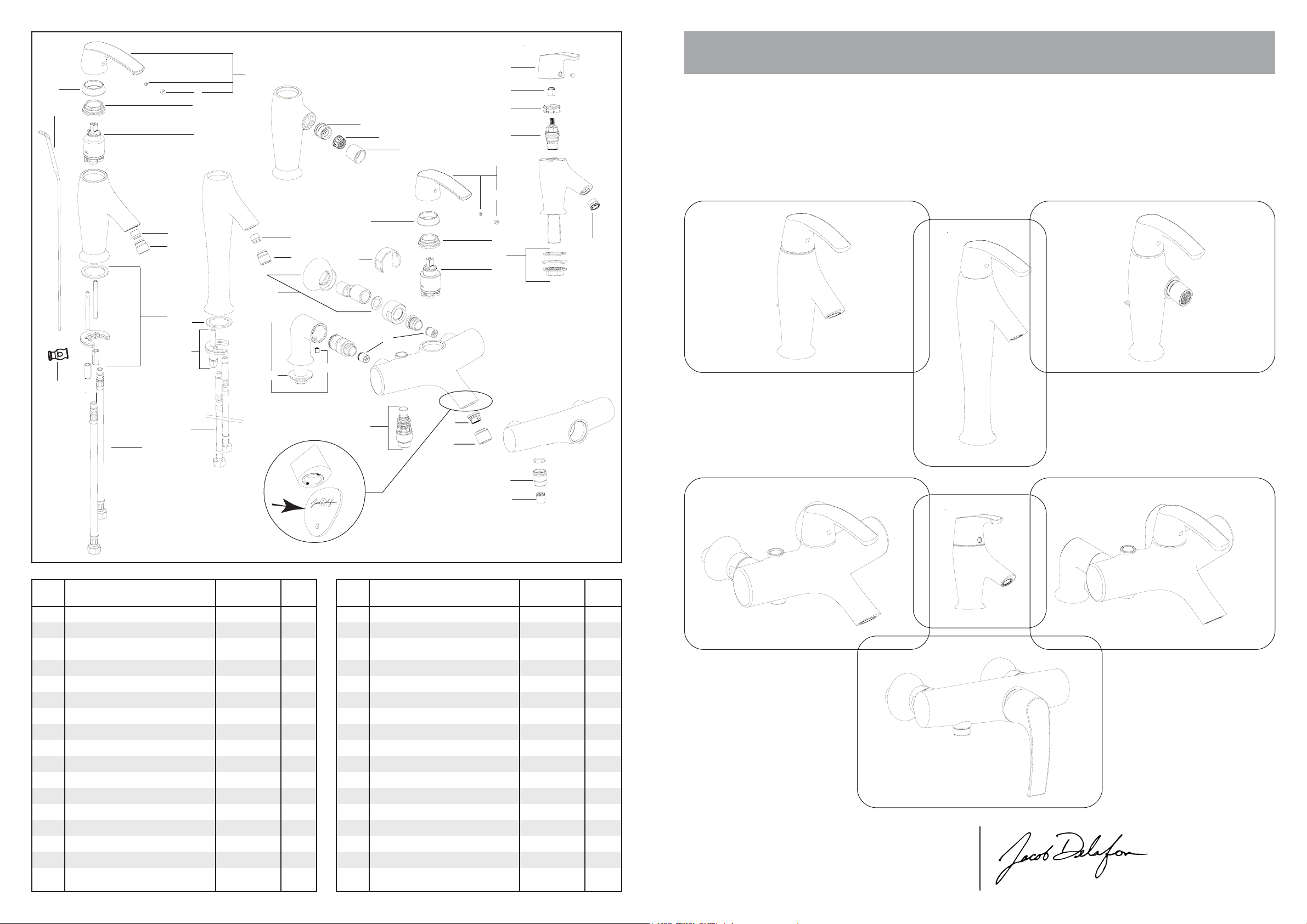
MITIGEUR MONOCOMMANDE
SINGLE CONTROL LEVER MIXER
2
3
7
8
9
26
27
14
25
8
18
4
33
34
5
17
15
16
24
23
.pe nR oitangiséD
1
2
3
4
5
6
7
8
9
01
11
21
31
41
51
61
71
28
19
10
20
21
22
Clé fournie
Supplied tool
16
ou 1 pièce 1 euro
or 1 coin 1 euro
edoC
elcitra
ehcaccevareiveL
ehcaC
ellepuoC
uorcE
euqimarécseuqsidàehcuotraC
etteritelbmesnE
ruetaréa'dreinaP
ruetaréa'degaC
noitaxifedelbmesnE
selbixelfederiaP
elutoR
ruetaréA
ruetaréa'degaC
etteritednoitaxiF
settennolocederiaP
ruoter-itnatepalC
secasorceva
seuqirtnecxesdroccarederiaP
PC-841A8E
FN941A8R
PC-051A8E
FN151A8R
85950392R
PC-251A8E
A376NF8R
PC-451A8E
40740392R
60740392R
PC-290A8E
96722392R
PC-551A8E
81840392R
PC-651A8E
25710392R
PC-161A8E
dnoC
rap
1
1
1
1
1
1
1
1
1
1
1
1
1
1
1
2
1
.pe nR oitangiséD
81
91
02
12
22
32
42
52
62
72
82
92
03
13
23
33
43
uorcé-egètorP
ruesrevnielbmesnE
ruetaréa'dreinaP
ruetaréa'degaC
tniojcevaelliuoD
siV
noitaxifedelbmesnE
ruetaréa'dreinaP
tnioJ
noitaxifedelbmesnE
selbixelfederiaP
ehcaccevareiveL
ruenîartnE
egateuqilcne'deugaB
T4/12/1GetiordCDetêT
ruetaréA
noitaxifedelbmesnE
edoC
elcitra
R8A604NF
dnoC
rap
FN061A8R
2
PC-751A8E
1
FN851A8R
1
PC-951A8E
1
96972992R
1
40440392R
1
FN900A8R
1
FN673A8R
1
48350392R
1
FN873A8R
1
FN773A8R
1
PC-794A8E
1
23110792R
5
61900792R
2
FN606A8R
1
1
55280992R
1
3900 6947 revision B 1/3
Une marque de la Société KOHLER FRANCE - 330 339 144 RCS BOBIGNY
Siège Social : Immeuble Le Cap - 3, rue de Brennus
TEL. : 33 (0) 1 49 17 37 37 - FAX : 33 (0) 1 49 17 37 40
SERVICE ASSISTANCE CLIENTÈLE : 0810 307 000
93631 La Plaine St Denis cedex
www.jacobdel afon.fr
www.jacobdel afon.es
SAT ESPAÑA Y PORTUGAL : 902 11 38 36
45
80
G1/2
140
42°
G 3/8
0 à 45
90
185
110
300
400
0 à 45
185
39°
300
44
G 3/8
E72680-..
220
110
90
0 à 45
39°
350
150 ± 15
90
G 1’’ 1/4
205
Ø 63
E19774-..
35 à 55
52
110
150 ± 15
44
G 3/8
E73680-..
222
110
85
0 à 45
150
350
G 1’’ 1/4
5°
120
205
Ø 63
35 à 55
52
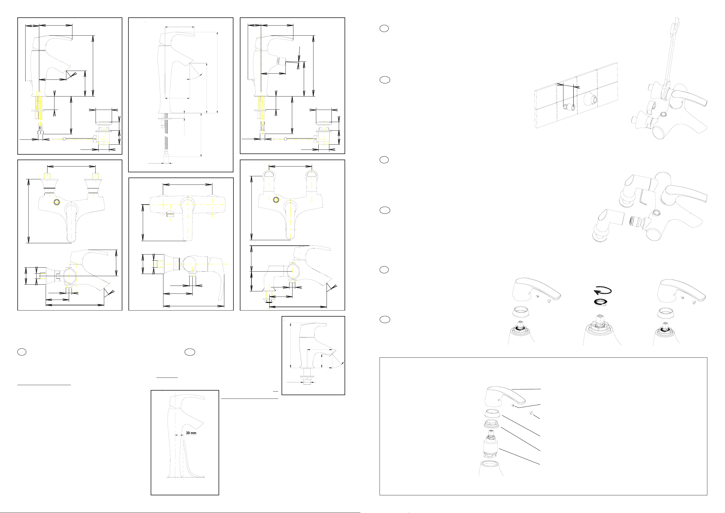
MONTAGE DES ROBINETTERIES MURALES / WALL INSTALLATION
F
• Déposer un join t d’étanchéité sur les raccords.
• Régler l’horizontalité des raccords en respectant la cote d’entr’axes de 150 mm avec un
dépassement de 40 à 45 mm depuis le mur fini.
• Visser les rosaces, positionner les joints d’étanchéité, visser les écrous à l’aide d’une clé plate de
41 avec le protège-écrou fourni.
• Bloquer.
GB
• Seal fittings.
• Install eccentric fittings horizontally, 150 mm
apart. They should extend 40 to 45 mm from finished wall.
• Screw on escutcheons, position washers and
then tighten nuts with an open-end wrench # 41
with the nut protector supplied.
• Lock in place.
40 à 45 mm
➀
➚
MONTAGE DES ROBINETTERIES SUR GORGE / DECK-MOUNT INSTALLATION
F
• Emboîter les colonnettes sur la robinetterie.
• Serrer sans bloquer les vis de fixation à la clé 6 pans mâle de 3.
• Présenter l’ensemble sur la baignoire, visser et bloquer les écrous de
colonnettes.
• Bloquer les vis de fixation.
• Raccorder.
➁
ª
GB
• Fix deck-mount connections to faucet.
• Insert fixing screws with an allen wrench.
• Position faucet on bathtub, screw and tighten nuts on connections.
•Tighten fixing screws.
• Connect faucet to water supply.
➚
➀
➚
➁
90
Ø 59
G 1/2
G 1/2
80
E71680-..
• Choix des bondes pour E19774-...
E78296-CP Bonde ‘Click’ pour vasque avec trop plein
E78292-CP Bonde à recouvrement courte (long. 50mm) sans trop plein
E78293-CP Bonde à recouvrement longue (long. 80mm) sans trop plein
200
39°
Ø 59
E71682-..
G 1/2
G 1/2
90
190
• Choise of the drains for the E19774-...
E78296-CP Clicker drain for vessel with over flow
E78292-CP Short cover drain for vessel (lgth. 50mm) without over flow
E78293-CP Long cover drain for vessel (lgth. 80mm) without over flow
CONSEILS A L'INSTALLATION / INSTALLATION INSTRUCTIONS
F
• Avant l'installation, purger soigneusement les canali-
sations. La robinetterie installée, démonter l’aérateur avant sa
mise en eau. Ouvrir l’eau. Pousser le levier à gauche (eau
chaude), à droite (eau froide) au maximum afin d’éliminer
toutes les impuretés par un écoulement abondant. Remonter
l’aérateur.
•Revêtement : la finition de ce mitigeur exige une
attention particulière : pour conserver l’aspect de
votre robinetterie, nettoyer régulièrement sa surface avec une éponge savonneuse non abrasive,
bien rincer et essuyer avec un linge doux. Eviter
formellement l'utilisation des produits contenant de
l'alcool méthylique, des acides, des solvants ou
des abrasifs qui endommageraient le revêtement.
• Chauffe-eau à gaz instantané
Pour son bon fonctionnement, il est conseillé :
• De régler le sélecteur de température au maximum.
• D’utiliser une eau à une pression statique de 1 bar
minimum, 6 bars maximum, 3 bars conseillés.
Montage de E19774 /
Installation of E19774
GB
• Drain pipes thoroughly
before installing. After installing
faucet, remove aerator. Turn on water
supply. Push lever as far to the left
(hot water) and to the right (cold
Vasque
→
Vessel
90
70
E71681-..
water) as possible to
remove all deposits
with a strong flow of water. Reinstall aerator.
• Finish: This mixer has a finish which requires
special care. To maintain its shine and luster,
clean regularly with a non-abrasive sponge and
soap, rinse thoroughly and dry with a soft cloth.
Do not use harsh products containing methyl
alcohol, acids, solvents or abrasives that can
damage the finish.
• Instantaneous gas water heater
Recommandations:
•Set temperature regulator at maximum position.
• Have static water pressure of at least 1 bar, 6
bars maximum, 3 bars advised.
G 1/2
82
39°
202
E12831-4-..
RÉGLAGE DE LA TEMPERATURE / ADJUSTING TEMPERATURE
Une bague-limiteur de température
F
(A), clipsée sur la cartouche, permet
de limiter le déplacement du levier
vers la gauche, et de diminuer ainsi la
température de l’eau chaude. (selon
➀➁➂➃➄)
A temperature-control ring (A)
GB
attached to the cartridge will control
leftward lever movement and thus
adjust the temperature of hot and
cold water. (according to ➀➁➂➃➄)
➀
➚
A
➛
➁
➚
CHANGEMENT DE LA CARTOUCHE / CHANGE OF THE VALVE
1. Fermer les arrivées d’eau.
T urn off the water supplies
to the faucet.
2. Oter le cache
Remove the cap.
3. Désserrer la vis du levier.
Loosen the setcrew.
4. Enlever le levier.
Lift the handle.
5. Dévisser la coupelle.
Loosen the bonnet.
6. Dévisser l’écrou.
Loosen the nut.
Levier
Lever
Vis
Screw
Cache
Cap
Coupelle
Bonnet
Ecrou
Nut
Cartouche
Cartridge
7. Déboîter la cartouche.
Lift the valve .
8. Inserrer la nouvelle cartouche.
Install the new valve.
9. Visser l’écrou.
Tighten the nut.
10. Visser la coupelle.
Tighten the bonnet.
1 1. Remonter le levier , serrer la vis.
Reinstall the lever, tighten the set screw .
12. Emboîter le cache.
Fit the cap and the lever together.
13. Ouvrir l’eau, vérifier le fonctionnement.
Turn on the water supplies, check the faucet.
➂
➚
➃
➚
➄
 Loading...