

Page 1

MODELS COVERED IN THIS MANUAL:
AJ-66CE
AJ-66CEL
MODELS FOR EXPORT ONLY
www.jacksonmsc.com
AJ-66 SERIES RACK CONVEYOR DISHMACHINES
(ELECTRICALLY HEATED)
September 28, 2001
P/N 7610-002-43-26 (Revision A)
I
N
S
T
A
L
L
A
T
I
O
N
&
O
P
E
R
A
T
I
O
N
M
A
N
U
A
L
Page 2

SECTION DESCRIPTION PAGE
I. GENERAL SECTION
Specifications 1
II. INSTALLATION & OPERATION SECTION
Installation Instructions 2
Operating Instructions 3
III. TROUBLESHOOTING SECTION 4
IV. DIMENSIONS 6
V. PARTS SECTION
AJ-66 Single Phase Control Box Assembly 8
AJ-66 Three Phase Control Box Assembly 10
Motor Overloads 12
Heater Box Assembly 13
Heater Box Cover/Thermostats 16
Wash Section Incoming Plumbing Assembly 17
Prewash Section Incoming Plumbing Assembly 18
AJ-66 (Left to Right) Drain Plumbing Assembly 19
AJ-66 (Right to Left) Drain Plumbing Assembly 20
Drain Handle Weldment Assembly/Frame Weldment 21
Motors/Motor Support Bracket Assembly 22
Wash Pump Assembly 23
Wash Pump Weldment 24
Prewash Pump Weldment 25
Assorted Gaskets 26
Wash Heaters/Hood Weldments/Tub Weldments 27
Wash Manifold, Prewash Manifold & Strainer Support Weldments 28
Upper Wash Arm Assembly 29
Lower Wash Arm Assembly 30
Prewash Arm Assembly 31
Final Rinse Assembly 32
Rinse Tray Assembly 33
Drive Assembly 34
Lubrication Chart for Gear Drive 37
Drive Motor Gear Reducer Preventative Maintenance 38
Wash Door and Vent Cowl Assembly 39
Miscellaneous Door Assemblies 40
AJ-66 (Left to Right) Rack Rail Assembly 41
AJ-66 (Right to Left) Rack Rail Assembly 42
Accuator Assemblies 43
Pawl Bar Roller Bracket 44
AJ-66 Pawl Bar Assembly 45
Miscellaneous Parts and Weldments 46
Strainers 49
Float Switch Assembly 50
Dress Panel 51
Magnet Switch Assemblies 52
Curtains 53
208 Volt/230 Volt - 50/60 Hz - Single Phase Schematic 54
208 Volt/220 Volt/230 Volt - 50/60 Hz - Three Phase Schematic 55
380 Volt/460 Volt/600 Volt - 60 Hz - Three Phase Schematic 56
380 Volt/415 Volt/440 Volt - 50 Hz - Three Phase Schematic 57
TABLE OF CONTENTS
i
Page 3
SPECIFICATIONS
1
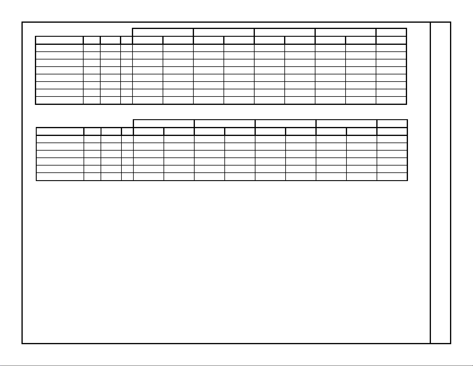
Drive Motor Prewash Motor Wash Motor Heater Load Total
Model Volts Phase Hz HP Amps HP Amps HP Amps KW Amps Amps
AJ-66CE/CEL 208 1 60 1/4 1.8 1 6 2 8.5 15 72 88.3
AJ-66CE/CEL 230 1 60 1/4 1.8 1 6 2 8.5 15 65.2 81.5
AJ-66CE/CEL 200 3 60 1/4 1.1 1 3.4 2 5.6 13.9 40.1 50.2
AJ-66CE/CEL 208 3 60 1/4 1.1 1 3.4 2 5.6 15 41.7 51.8
AJ-66CE/CEL 230 3 60 1/4 1.1 1 3.4 2 5.6 15 37.7 47.8
AJ-66CE/CEL 380 3 60 1/4 0.55 1 1.8 3 5.1 15 22.8 30.3
AJ-66CE/CEL 460 3 60 1/4 0.55 1 1.7 2 2.8 15 18.8 23.9
AJ-66CE/CEL 600 3 60 1/4 0.46 2 2.8 2 2.8 16.3 15.7 21.8
RACKS PER HOUR:
AJ-66CE: 248
AJ-66CEL: 234
DISHES OR GLASSES PER HOUR:
AJ-66CE: 6200
AJ-66CEL: 5850
WASH TANK CAPAITY (GALLONS):
ALL MODELS: 15.4
PREWASH TANK CAPACITY (GALLONS):
ALL MODELS: 16
WASH PUMP CAPACITY:
GALLONS PER MINUTE: 270
PREWASH PUMP CAPACITY (GPM):
ALL MODELS: 120
VENTING REQUIREMENTS (CFM)(100% CAP.):
INPUT END: 200
OUTPUT END: 400
TOTAL: 600
CONVEYOR SPEED (FPM):
CE MACHINES: 6.9
CEL MACHINES: 6.5
GALLONS PER RACK:
CE MACHINES: .94
CEL MACHINES: 1.00
WATER TEMPERATURES (
°
F):
CE MODELS:
PREWASH (MINIMUM) 110
WASH (MINIMUM) 160
RINSE (MINIMUM) 180
CEL MODELS:
PREWASH (MINIMUM) 110
PREWASH (RECOMMENDED) 140
WASH (MINIMUM) 140
RINSE (MINIMUM) 140
FLOW PRESSSURE (PSI) 20
FLOWRATE (GPM) 3.9
MINIMUM CHLORINE (PPM) 50
(CEL MODELS ONLY)
Drive Motor Prewash Motor Wash Motor Heater Load Total
Model Volts Phase Hz HP Amps HP Amps HP Amps KW Amps Amps
AJ-66CE/CEL 208 3 50 1/3 0.6 1 3.6 3 12 15 41.7 57.9
AJ-66CE/CEL 220 3 50 1/3 0.6 1 3.6 3 12 13.7 36 52.2
AJ-66CE/CEL 230 3 50 1/3 0.6 1 3.6 3 12 15 37.7 53.9
AJ-66CE/CEL 380 3 50 1/3 0.6 1 1.8 3 5.1 15 22.8 30.3
AJ-66CE/CEL4153501/30.636361520.933.5
AJ-66CE/CEL4403501/30.6353516.822.132.7
Page 4

Jackson MSC Inc. provides technical support for all of the dishmachines
detailed in this manual. We strongly recommend that you refer to this manual before making a call to our technical support staff. Please have this
manual with you when you call so that our staff can refer you, if necessary ,
to the proper page. Technical support is avaliable from 8:00 a.m. to 5:00
p.m. (EST), Monday through Friday. Technical support is not available on
holidays. Contact technical support toll-free at 1-888-800-5672. Please
remember that technical support is available for service personnel only.
VISUAL INSPECTION: Before installing the unit, check the container and
machine for damage. A damaged container is an indicator that there may
be some damage to the machine. If there is damage to both the container
and machine, do not throw away the container. The dishmachine has been
inspected and packed at the factory and is expected to arrive to you in
new, undamaged condition. However, rough handling by carriers or others
may result in there being damage to the unit while in transit. If such a situation occurs, do not return the unit to Jackson; instead, contact the carrier and ask them to send a representative to the site to inspect the damage to the unit and to complete an inspection report. You must contact the
carrier within 48 hours of receiving the machine. Also, contact the dealer
through which you purchased the unit.
UNPACKING THE DISHMACHINE:Once the machine has been removed
from the container, ensure that there are no missing parts from the
machine. This may not be obvious at first. If it is discovered that an item is
missing, contact Jackson immediately to have the missing item shipped to
you.
LEVEL THE DISHMACHINE: The dishmachine is designed to operate
while being level. This is important to prevent any damage to the machine
during operation and to ensure the best results when washing ware. The
unit comes with adjustable bullet feet, which can be turned using a pair of
channel locks or by hand if the unit can be raised safely. Ensure that the
unit is level from side to side and from front to back before making any
connections.
PLUMBING THE DISHMACHINE: All plumbing connections must comply
with all applicable local, state, and national plumbing codes. The plumber
is responsible for ensuring that the incoming water line is throroughly
flushed prior to connecting it to any component of the dishmachine. It is
necessary to remove all foreign debris from the water line that may potentially get trapped in the valves or cause an obstruction. Any valves that are
fouled as a result of foreign matter left in the water line, and any expenses resulting from this fouling, are not the responsibility of the manufacturer.
CONNECTING THE DRAIN LINE: The drain for the models covered in
this manual are gravity disharge drains. All piping from the 1-1/2” MNPT
connection must be pitched (1/4” per foot) to the floor or sink drain. All piping from the machine to the drain must be a minimum 1-1/2” I.P.S. and
shall not be reduced. There must also be an air gap between the machine
drain line and the floor sink or drain. If a grease trap is required by code,
it should have a flow capacity of 30 gallons per minute.
WATER SUPPLY CONNECTION: Ensure that you have read the section
entitled “PLUMBING THE DISHMACHINE” above before proceding. Install
the water supply line (3/4” pipe size minimum) to the dishmachine line
strainer using copper pipe. It is recommended that a water shut-off valve
be installed in the water line between the main supply and the machine to
allow access for service. The water supply line is to be capable of 25 PSI
“flow” pressure at the recommended temperature indicated on the data
plate.
In areas where the water pressure fluctuates or is greater than the recommended pressure, it is suggested that a water pressure regulator be
installed. The models covered in this manual do not come with water pressure regulators as standard equipment.
Do not confuse static pressure with flow pressure. Static pressure is the
line pressure in a “no flow” condition (all valves and services are closed).
Flow pressure is the pressure in the fill line when the fill valve is opened
during the cycle.
It is also recommended that a shock absorber (not supplied) be installed
in the incoming water line. This prevents line hammer (hydraulic shock),
induced by the solenoid valve as it operates, from causing damage to the
equipment.
PLUMBING CHECK: Slowly turn on the water supply to the machine after
the incoming fill line and the drain line have been installed. Check for any
leaks and repair as required. All leaks must be repaired prior to placing the
machine in operation.
ELECTRICAL POWER CONNECTION: Electrical and grounding connections must comply with the applicable portions of the National Electrical
Code ANSI/NFPA 70 (latest edition) and/or other electrical codes.
Disconnect electrical power supply and place a tag at the disconnect
switch to indicate that you are working on the circuit.
The dishmachine data plate is located on the right side and to the front of
the machine. Refer to the data plate for machine operating requirements,
machine voltage, total amperage load and serial number.
To install the incoming power lines, open the control box. Install conduit
into the pre-punched holes in the back of the control box. Route power
wires and connect to power block and grounding lug. Install the service
wires (L1, L2, and L3 (3 phase only)) to the appropriate terminals as they
are marked on the terminal block. Install the grounding wire into the lug
provided. Tighten the connections. It is recommended that “DE-OX” or
another similar anti-oxidation agent be used on all power connections.
VOLTAGE CHECK: Ensure that the power switch is in the OFF position
and apply power to the dishmachine. Check the incoming power at the terminal block and ensure it corresponds to the voltage listed on the data
plate. If not, contact a qualified service agency to examine the problem. Do
not run the dishmachine if the voltage is too high or too low. Shut off the
service breaker and mark it as being for the dishmachine. Advise all proper personnel of any problems and of the location of the service breaker.
Replace the control box cover and tighten down the screws.
VENTILATION OF DISHMACHINE: The dishmachine should be located
with provisions for venting into an adequate exhaust hood or ventilation
system. This is essential to permit efficient removal of the condensation
exhaust. Ensure that the exhaust system is acceptable in accordance with
all applicable codes and standards.
NOTE: Damage caused by steam or moisture due to improper ventilation is NOT covered under the warranty.
This units covered in this manual have the following exhaust requirements:
Load End: 200 CFM
Unload End: 400 CFM
The exhaust system must be sized to handle this volume for the dishma-
chine to operate as it was designed to.
ELECTRIC HEAT: The thermostats for the machines covered in this man-
ual are factory set. They should not be adjusted except by an authorized
service agent.
INSTALLATION INSTRUCTIONS
2
Page 5

CHEMICAL FEEDER EQUIPMENT: The AJ-66CEL is designed to operate with a third party chemical injection system. Jackson does not endorse
any particular chemical injection system. The system selected must be
able to provide detergent and sanitizer in the required concentrations. The
minimum chlorine concentration for proper sanitization is 50 PPM.
Furthermore, the selected feeder needs to be able to operate against a
head of 25 PSI and deliver 7.38 ml of a 10% chlorine sanitizer per minute.
Detergent may be introduced into the unit through the removal of the bulkhead plug in the rear of the tub and replacing it with the third party detergent injection fitting. Remove the bulkhead plug in the side of the tub to
install the detergent concentration probe.
The 1/8” brass plugs on the incoming plumbing rinse injector may be
removed to install sanitizer and rinse aid injection fittings.
All wires for the chemical injectors should be routed through the back of
the control box.
Terminals in the control box marked “CVS” provide a constant voltage signal whenever the drive motor is operating.
Terminals in the control box marked “DET” provide a voltage signal whenever the wash motor is operating.
DELIMING OPERATIONS: In order to maintain the dishmachine at its
optimum performance level, it will be required to remove lime and corrosion deposits on a frequent basis. A deliming solution should be available
from your detergent supplier. Read and follow all instructions on the label
of the deliming solution.
To proceed with the deliming operation, fill the dishmachine and add the
correct amount of deliming solution as recommended by the deliming solution manufacturer. The water capacity of the various tanks of the dishmachine can be verified on the specification sheet(s) of this manual.
Perform the following operations to delime the dishmachine:
1. Turn the NORMAL/DELIME switch on the back of the control box to the
DELIME position.
2. Disconnect or turn off all chemical feeder pumps.
3. Close all doors (after adding the deliming solution).
4. Run the machine for the recommended period of time.
5. Turn the unit off and open the doors.
6. Wait five minutes, then inspect the inside of the machine. If the machine
is not delimed, run another time cycle as per the deliming solution’s
instructions.
7. When clean, drain and re-fill the machine.
8. Run in MANUAL for 10 minutes to remove residual deliming solution.
9. Drain and re-fill the machine.
OPERATING INSTRUCTIONS
PREPARATION: Before proceeding with the start-up of the unit, verify the
following:
1. Close door(s) on dishmachine.
2. Close the drain valve(s).
POWER UP: To energize the unit, turn on the power at the service breaker. The voltage should have been previously verified as being correct. If
not, the voltage will have to be verified.
FILLING THE WASH TUB: Ensure that the delime switch is in the NORMAL position, and place the power switch into the ON position. The
machine should fill automatically and shut off when the appropriate level is
reached (just below the pan strainer). The wash tub must be completely
filled before operating the wash pump to prevent damage to the component. Once the wash tub is filled, the unit is ready for operation.
WARE PREPARATION: Proper preparation of ware will help ensure good
results and less re-washes. If not done properly, ware may not come out
clean and the efficiency of the dishmachine will be reduced. It is important
to remember that a dishmachine is not a garbage disposal and that simply throwing unscrapped dishes into the machine simply defeats the purpose altogether of washing the ware. Scraps should be removed from
ware prior to being loaded into a rack. Pre-rinsing and pre-soaking are
good ideas, especially for silverware and casserole dishes. Place cups
and glasses upside down in racks so that they do not hold water during the
cycle. The dishmachine is meant not only to clean, but to sanitize as well,
to destroy all of the bacteria that could be harmful to human beings. In
order to do this, ware must be properly prepared prior to being placed in
the machine.
DAILY MACHINE PREPARATION: Refer to the section entitled “PREPARATION” at the top of this page and follow the instructions there.
Afterwards, check that all of the chemical levels are correct and/or that
there is plenty of detergent available for the expected workload.
WASHING A RACK OF WARE: To wash a rack, simply slide a rack of
soiled ware into the load end of the machine. Once the the machine is
started, it should pull the rack through the machine and push it out the
unload end. Once a rack has started through, you may put another rack in.
OPERATIONAL INSPECTION:Based upon usage, the pan strainers may
become clogged with soil and debris as the workday progresses.
Operators should reguarly inspect the pan strainers to ensure they have
not become clogged. If the strainers do, they will reduce the washing
capability of the machine. Instruct operators to clean out the pan strainers
at regular intervals or as required by work load.
NOTE: On units equiped with prewash sections (AJ-66 and AJ-80), operators should also take the time to inspect the prewash section strainers
and clean them as required by workload.
SHUTDOWN AND CLEANING: At the end of the workday, place the
power switch in the OFF position and open the door(s). Open the drain
valves and allow the machine to drain completely. Remove the pawl bar
assembly (clean as required). Remove the
pan strainers and, if equiped, the prewash strainers, run off sheets and
scrap basket strainer. Remove the wash and, if equipped, the prewash
arms and verify that the nozzles and arms are free from obstructions.
Flush the arms with fresh water. Remove the pump suction strainers and
clean out as required. Remove the rinse tray assembly and clean. Remove
the curtains and scrub with a mild detergent and warm water. Wipe out the
inside of the unit and then reassemble with the components previously
removed.
INSTALLATION INSTRUCTIONS (CONTINUED)/OPERATING INSTRUCTIONS
3
Page 6

Problem: Nothing on dishmachine operates. The power switch is ON and the power indicator light is OFF.
Possible causes:
1. Machine is not wired correctly to incoming power source. Have an electrician verify wiring.
2. Machine circuit breaker is tripped. Reset the circuit breaker. If it trips again, contact an electrician to verify the machine amp draw.
3. Service breaker is tripped. Reset the service breaker. If it trips again, contact an electrician to verify the machine amp draw.
Problem: Machine will not fill. The power switch is ON and the power indicator light is ON.
Possible causes:
1. No water supply to machine. Verify that water lines have been connected to the machine.
2. Dishmachine doors are not closed. Close doors completely.
3. Incoming water solenoid valve damaged/faulty. Verify that the valve is operating. If not, replace.
4. Tank floats faulty. Verify the wiring of the floats. Verify that no debris is jamming the floats. Replace if necessary.
Problem: Machine fills, but fill is weak.
Possible causes:
1. Low incoming water pressure. Verify that incoming water pressure during fill is 20 PSI.
2. Incoming water solenoid is clogged. Verify that debris is not entrapped in valve. If so, remove debris.
Problem: Low wash tank temperature.
Possible causes:
1. Low incoming water temperature. Verify that the incoming water temperature matches what is indicated on the machine data plate.
2. Heater not energizing. Verify that the wash tank heater is operating. If not, replace.
3. Low incoming voltage. Have an electrician verify that the power coming to the machine is the same as indicated on the data plate.
Problem: Low wash arm pressure, poor spray pattern.
Possible causes:
1. Clogged wash arm nozzles. Verify that nozzles are not clogged with debris. If so, remove debris.
2. Clogged wash tank or wash pump strainers. Clean out strainers if necessary.
3. Worn wash pump impeller. Verify status of impeller, replace if necessary.
Problem: Low prewash arm pressure, poor spray pattern.
Possible causes:
1. Clogged prewash arm nozzles. Verify that nozzles are not clogged with debris. If so, remove debris.
2. Clogged prewash tank or prewash pump strainers. Clean out strainers if necessary.
3. Worn prewash pump impeller. Verify status of impeller, replace if necessary.
Problem: Inadequate rinse.
1. Low incoming water pressure. Verify that incoming water pressure during fill is 20 PSI.
2. Incoming water solenoid is clogged. Verify that debris is not entrapped in valve. If so, remove debris.
Problem: Pawl bar moves with no load, but does not move when loaded.
1. Clutch on drive assembly is out of adjustment. Adjust as required.
Problem: Pawl bar does not move.
1. Failed or broken overload spring. Replace spring if necessary.
2. No power to the drive motor/failed drive motor. Verify power and wiring connections to the motor. If necessary, replace the motor.
3. Pawl bar not properly installed. Verify that the pawl bar is installed correctly.
TROUBLESHOOTING SECTION
4
Page 7

Problem: Racks go through the machine, but results are poor.
1. Verify that detergent is being dispensed into the machine at the appropriate quantities for the water volume. If not, get detergent to appropriate level
and review results of washing ware.
2. Clogged strainers/scrap basket. Clean out strainers and scrap basket and replace.
3. Ware not being properly prescrapped. Review paragraph entitled ‘Ware Preperation” in Operating Instructions.
4. Wash or rinse arms missing end plugs or caps. Verify and replace as required.
5. Low tank heat (see previous page).
6. Inadequate rinse (see previous page).
7. Incorrect voltage coming to the machine. Verify that the voltage matches that on the machine data plate.
8. Wash pump cavitation due to low water level. Verify that the drains are shut and that the water level is correct.
Problem: Sotting of silverware, glasses and dishes.
1. Incorrect final rinse temperature. Verify that the rinse water temperature matches that which is listed on the machine data plate.
2. Clogged wash and/or rinse nozzles and arms. Remove the arms and verify that they and their nozzles are from debris.
3. Excessively hard water. Install a water softener to reduce hardness.
4. Loss of water pressure due to clogged/obstructed wash pump. Turn the power off to the machine at the source. Drain the wash tank of water and
verify that the pump intake is free from debris.
5. Improper scrapping procedures. Review the paragraph entitled “Ware Preperation” in Operating Instructions.
6. incorrect detergent/chemcial concentrations. Verify that the detergent/chemical concentrations are correct for the associated water volume.
TORQUE SETTINGS
When replacing components either in the control box or the heater box area, the manufacturer has suggestions on how much to torque the screws
and nuts used in securing items to the machine. Refer to the table below for the torque specifictions:
ITEMS
TORQUE SPEC
Relays 16 In/lbs
Heater Contactor 35 In/lbs
Heater Nuts 16 In/lbs
Terminal Block 50 In/lbs
TROUBLESHOOTING SECTION (CONTINUED)
5
Page 8
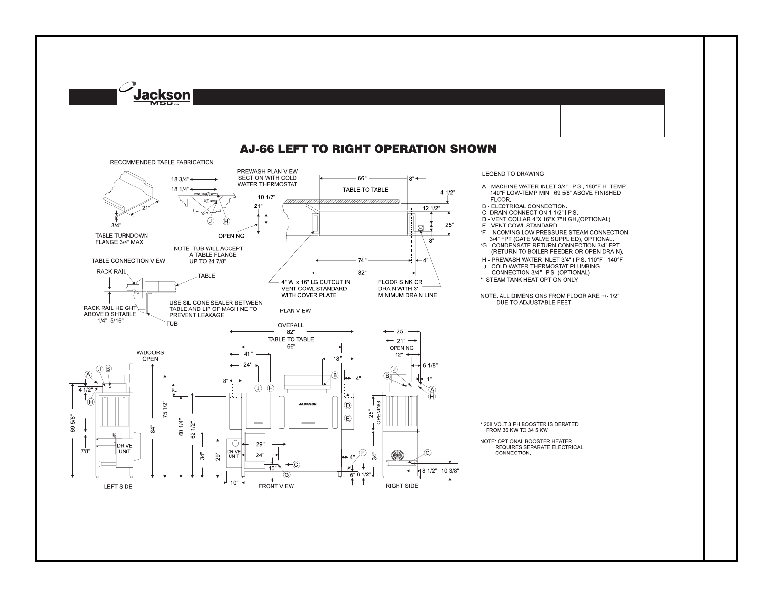
AJ-66 (LEFT TO RIGHT DIRECTION) DIMENSIONS
6
AJ-66 Vision Series
Single-Tank Rack
Conveyor Dishwashers
Page 9
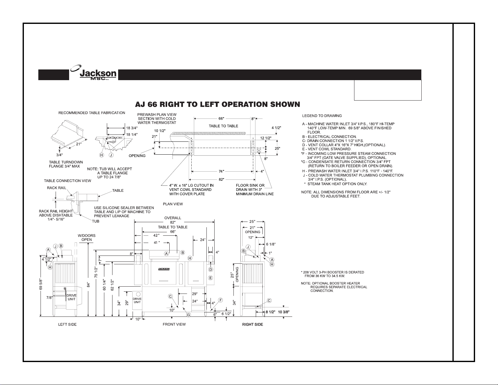
AJ-66 (RIGHT TO LEFT DIRECTION) DIMENSIONS
7
AJ-66 Vision Series
Single-Tank Rack
Conveyor Dishwashers
Page 10
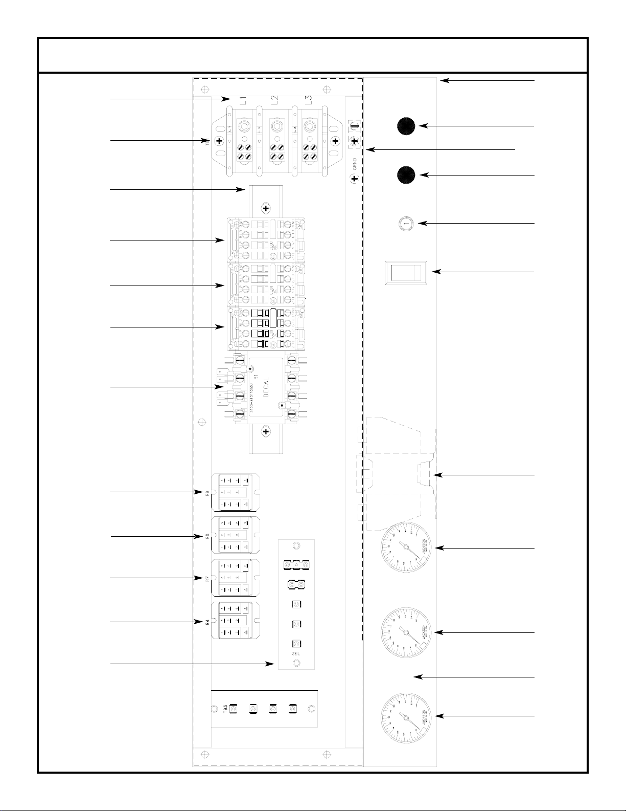
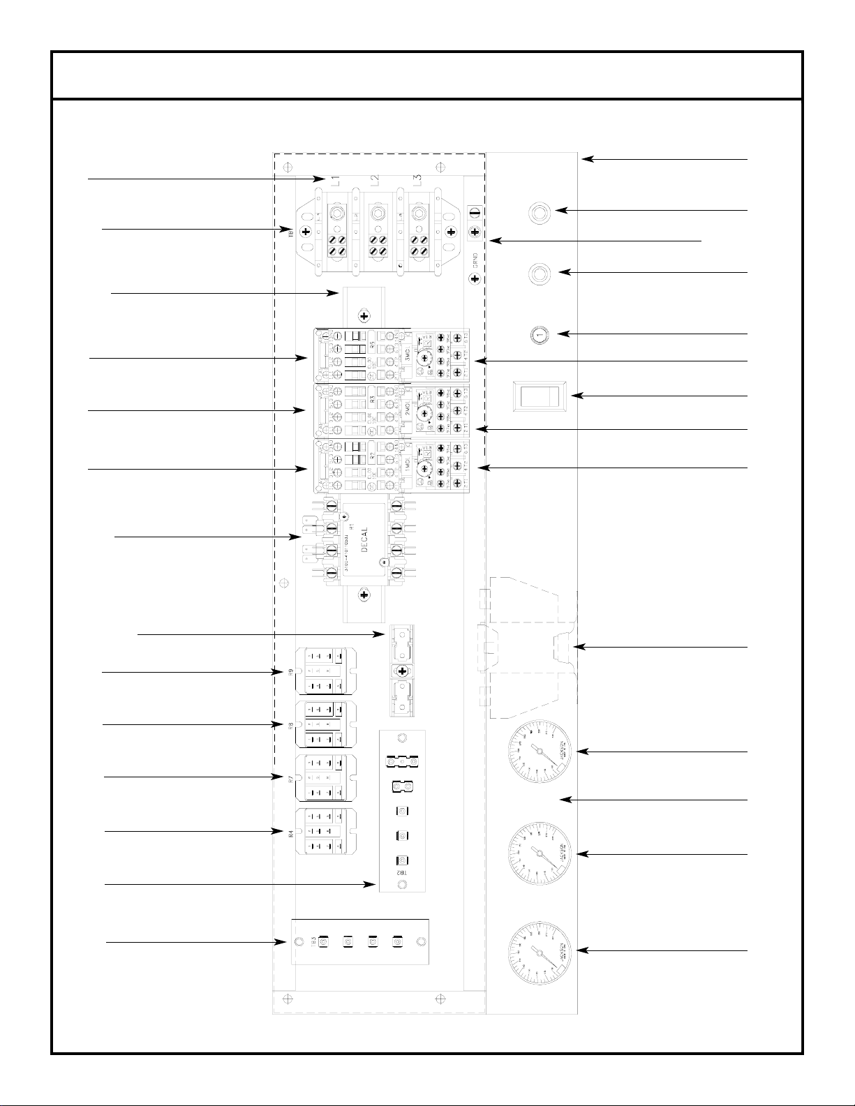
AJ-66 SINGLE PHASE CONTROL BOX ASSEMBLY
8
1
2
3, 4, 5
6
8
4, 7, 10, 11, 12
4, 9, 10
15
14
14
14
16
10, 18
19, 20
21, 22
21, 22
21, 22
21, 23
13, 21
24
25
25
26
Page 11
MISCELLANEOUS PARTS NOT SHOWN:
Grommet, 1/2” OD x 3/8” ID 5325-011-46-73
Bushing, Heyco SB100 5975-210-09-00
Plug, Heyco 2700 G-875 5975-011-47-81
Control Box Cover 5700-031-89-42
Control Box Cover Hinge Weldment 5700-021-68-57
Control Hinge Rod 5700-011-68-58
Washer, Flat, S/S, 1/4” ID 5311-174-01-00
Cotter Pin 5315-011-68-56
MANUAL/DELIME Switch (located on rear of control box) 5930-301-22-18
MANUAL/DELIME Switch Decal (located on rear of control box) 9905-011-74-61
Copper Conductors Only Decal 9905-011-47-35
Control Box Leg 5700-011-71-47
Bolt, 1/4”-20 x 2-1/2” Long Hex Head 5306-011-83-52
Locknut, 1/4”-20 with Nylon Insert 5310-374-01-00
Component Mounting Plate (located inside the control box) 5700-031-67-03
AJ-66 SINGLE PHASE CONTROL BOX ASSEMBLY (CONTINUED)
9
ITEM QTY DESCRIPTION MFG No.
1 1 Electrical Box Weldment 5700-041-88-50
2 1 Decal, L1-L2-L3 9905-101-12-66
3 1 Terminal Block 5940-011-48-27
4 6 Lockwasher, #10 5311-273-02-00
5 2 Screw, 10-32 x 3/4" Long Phillips Trusshead 5305-011-62-17
6 1 Light, Amber 5945-111-44-44
7 1 Wire Lug, 2 AWG to 14 AWG 5940-200-76-00
8 1 Light, Red 5945-111-44-45
9 1 Din Rail 5700-021-72-75
10 3 Screw, 10-32 x 1/2" Long Phillips Trusshead 5305-011-39-36
11 1 Washer, Flat, 1/4" ID 5311-174-01-00
12 1 Decal, Ground 9905-011-86-86
13 1 Terminal Board 5940-021-70-70
14 3 Motor Contactor 5945-111-68-38
15 1 Circuit Breaker 5925-011-68-34
16 1 Switch, ON/FILL & OFF/DRAIN 5930-301-46-00
17 1 Heater Contactor 5945-111-68-37
18 1 Transformer 5950-011-68-35
19 4 Locknut, 10-24 with Nylon Insert 5310-373-01-00
20 12 Screw, 6-32 x 3/8" Long Phillipshead 5305-171-02-00
21 3 Control Relay 5945-111-35-19
22 1 Relay 5945-111-72-51
23 1 Thermometer, 48" Lead 6685-111-68-48
24 2 Thermometer, 96" Lead 6685-111-68-49
25 1 Decal, AJ-66 Gauge 9905-021-72-30
26 1 Terminal Board 5940-021-89-41
Page 12
AJ-66 THREE PHASE CONTROL BOX ASSEMBLY
10
1
2
3, 4, 5
6
4, 7, 10, 11, 12
8
4, 9, 10
14
14
14
15
16
17
18
19
20, 21
22, 23
24, 25, 26
26, 27
26, 27
26, 27
26, 28
29
31
30
30
13, 26
26,32
Page 13

MISCELLANEOUS PARTS NOT SHOWN:
Grommet, 1/2” OD x 3/8” ID 5325-011-46-73
Bushing, Heyco SB100 5975-210-09-00
Plug, Heyco 2700 G-875 5975-011-47-81
Control Box Cover 5700-031-89-42
Control Box Cover Hinge Weldment 5700-021-68-57
Control Hinge Rod 5700-011-68-58
Washer, Flat, S/S, 1/4” ID 5311-174-01-00
Cotter Pin 5315-011-68-56
MANUAL/DELIME Switch (located on rear of control box) 5930-301-22-18
MANUAL/DELIME Switch Decal (located on rear of control box) 9905-011-74-61
Copper Conductors Only Decal 9905-011-47-35
Control Box Leg 5700-011-71-47
Bolt, 1/4”-20 x 2-1/2” Long Hex Head 5306-011-83-52
Locknut, 1/4”-20 with Nylon Insert 5310-374-01-00
Component Mounting Plate (located inside the control box) 5700-031-67-03
AJ-66 THREE PHASE CONTROL BOX ASSEMBLY (CONTINUED)
11
ITEM QTY DESCRIPTION MFG No.
1 1 Electrical Box Weldment 5700-041-88-50
2 1 Decal, L1-L2-L3 9905-101-12-66
3 1 Terminal Block 5940-011-48-27
4 6 Lockwasher, #10 5311-273-02-00
5 2 Screw, 10-32 x 3/4" Long Phillips Trusshead 5305-011-62-17
6 1 Light, Amber 5945-111-44-44
7 1 Wire Lug, 2 AWG to 14 AWG 5940-200-76-00
8 1 Light, Red 5945-111-44-45
9 1 Din Rail 5700-021-72-75
10 3 Screw, 10-32 x 1/2" Long Phillips Trusshead 5305-011-39-36
11 1 Washer, Flat, 1/4" ID 5311-174-01-00
12 1 Decal, Ground 9905-011-86-86
13 1 Terminal Board 5940-021-70-70
14 3 Motor Contactor 5945-111-68-38
15 1 Circuit Breaker (200/ 208/220/230/380 (60 Hz) Volt Models Only) 5925-011-68-34
16 1 See Page Entitled "Motor Overloads" N/A
17 1 Switch, ON/FILL & OFF/DRAIN 5930-301-46-00
18 1 See Page Entitled "Motor Overloads" N/A
19 1 See Page Entitled "Motor Overloads" N/A
20 1 Heater Contactor 5945-002-24-70
21 2 Screw, 10-32 x 3/8" Long Phillips Trusshead 5305-173-12-00
22 1 Transformer (200 Volt Models Only) 5950-002-41-47
22 1 Transformer (208/220/230/460 Volt Models Only) 5950-011-68-35
22 1 Transformer (380/415 Volt Models Only) 5950-011-75-59
22 1 Transformer (600 Volt Models Only) 5950-002-23-77
23 4 Locknut, 10-24 with Nylon Insert 5310-373-01-00
24 1 Fuse Holder (380 (60 Hz)/ 460/600 Volt Models Only) 5920-011-72-89
25 1 Fuse (380 (60 Hz)/460/600 Volt Models Only) 5920-011-72-88
26 12 Screw, 6-32 x 3/8" Long Phillipshead 5305-171-02-00
27 3 Control Relay 5945-111-35-19
28 1 Relay 5945-111-72-51
29 1 Thermometer, 48" Lead 6685-111-68-48
30 2 Thermometer, 96" Lead 6685-111-68-49
31 1 Decal, AJ-66 Gauge 9905-021-72-30
32 1 Terminal Board 5940-021-89-41
Page 14

Model Volts Hz Phase Drive Motor Prewash Motor Wash Motor
AJ-66CE/CEL 208 50 3 5945-011-84-59 5945-002-24-70 5945-111-68-40
AJ-66CE/CEL 220 50 3 5945-011-84-59 5945-002-24-70 5945-111-68-40
AJ-66CE/CEL 230 50 3 5945-011-84-59 5945-002-24-70 5945-111-68-40
AJ-66CE/CEL 380 50 3 5945-111-69-12 5945-002-24-70 5945-111-81-33
AJ-66CE/CEL 415 50 3 5945-111-69-12 5945-002-24-70 5945-111-81-33
AJ-66CE/CEL 440 50 3 5945-111-69-12 5945-002-24-70 5945-111-81-33
AJ-66CE/CEL 208 60 1 N/A N/A N/A
AJ-66CE/CEL 230 60 1 N/A N/A N/A
AJ-66CE/CEL 200 60 3 5945-111-68-39 5945-111-68-41 5945-111-68-40
AJ-66CE/CEL 208 60 3 5945-111-68-39 5945-111-68-41 5945-111-68-40
AJ-66CE/CEL 230 60 3 5945-111-68-39 5945-111-68-41 5945-111-68-40
AJ-66CE/CEL 380 60 3 5945-111-69-12 5945-002-24-70 5945-111-81-33
AJ-66CE/CEL 460 60 3 5945-111-68-39 5945-111-68-41 5945-111-68-40
AJ-66CE/CEL 600 60 3 5945-111-69-12 5945-002-24-70 5945-111-68-41
MOTOR OVERLOADS
12
Page 15
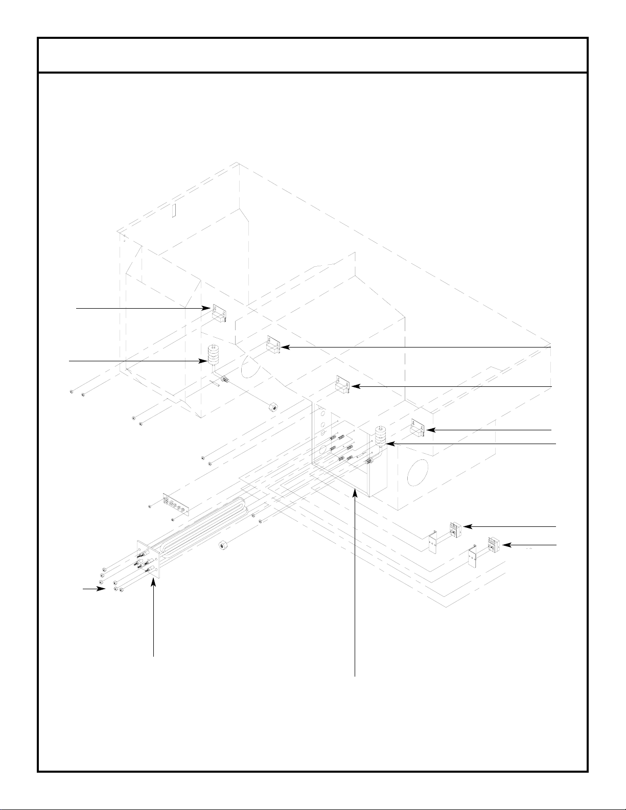
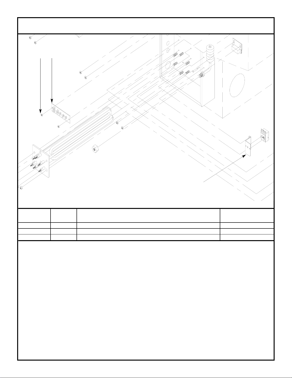
HEATER BOX ASSEMBLY
13
1, 2
3, 4, 5
6
7
8
9
10, 11
12, 14
12, 14
12, 14
13, 15
AJ-66 TUB
Page 16
The wash tank heater system is electrically connected in the circuit so that they are dependent upon the dishwasher being properly
filled with and maintaining a safe water level, two thermostats (mounted in the heater box behind the dress panel), float switch
(mounted in the wash tank), and the heater relay (mounted in control box) with the heater being activated by the thermostats.
Once the dishwasher has been filled to the correct level, the heater should operate automatically. Should the tank heat be too high,
too low or no indication of temperatures at all, the following checkout should be made.
Note: The following checkout should be made by either a qualified service person or electrician.
A.- Checkout of the heater system
1.- If the temperature is too high, adjust thermostat using instructions on the page entitled “Thermostats”.
2.- If temperature is too low, adjust thermostat as above, then:
a.- Turn off power to machine by placing customer’s circuit breaker in the “OFF” position. Turn off machine circuit
breaker located on right side of control box.
b.- Remove cover from control box on top of dishwasher.
c.- Make sure water temperature is below 140 degrees F.(preferably about 130 degrees F.).
d.- Turn on both circuit breakers. Observe heater relay (R1) while the power switch is turned “ON” and “OFF”. If relay
contacts move in and out, the heater relay is operating correctly: if not proceed to ”C”.
B.- If heater relay (R1) closes:
1.- Check power supply at incoming terminal board L1, L2 & L3. It should be the same voltage as indicated on the
machine data plate.
2.- Check power at connections on heater relay (R1). The voltage should agree with the voltage on the machine data
plate. If not, check wires for breaks or bad connections.
3.- Check power at terminals of heater which should agree with the data plate. If not check wires for breaks or bad con
-nections.
4.- Temperatures should rise as explained in “C-1”, and amperage may be checked according to those instructions.
Replace any defective elements.
C.- If heater relay (R1) does not close.
1.- There is an insulated movable insulated movable bar on relay across the top. With an insulated probe, depress this
bar and observe the thermometer: the temperature should rise noticeably in a minute or two. If it moves slowly, it
would indicate that the element is faulty. If it moves constantly higher at a good rate, elements should be good.
Note: A check with an amp probe at heater relay (R1) terminals should be made to verify the amp draw on each leg. This
should be appropriate for the voltage and phase indicated on the data plate.
HEATER BOX ASSEMBLY (CONTINUED)
14
ITEM QTY DESCRIPTION MFG No.
1 1 See Page Entilted "Wash Heaters" N/A
2 1 Heater Gasket 5330-200-02-70
3 6 Washer, Flat, 5/16" 5311-175-01-00
4 6 Lockwasher, 5/16" 5311-275-01-00
5 6 Nut, 5/16"-18 5310-275-01-00
6 1 Thermostat, Wash Regulating 5930-121-67-72
7 1 Thermostat, High Limit Control 5930-121-71-36
8 1 Float Switch (Wash Tank) 6680-121-70-71
9 1 Float Switch (Prewash Tank) 6680-121-70-16
10 1 Heater Box Weldment (A J-44 Only) 5700-031-66-81
10 1 Heater Box Weldment (A J-66/AJ-80 Only) 5700-031-71-66
11 6 Locknut, 1/4"-20 with Nylon Insert 5310-374-01-00
12 3 Reed Switch (All Models) 5930-111-68-44
13 1 Reed Switch (AJ-66 and AJ-80 Models Only) 5930-111-68-44
14 3 Reed Switch Bracket (All Models) 5700-021-71-18
15 1 Reed Switch Bracket (AJ-66 and AJ-80 Models Only) 5700-021-71-18
Page 17
HEATER PROTECTION & AUTOMATIC FILL
This control is activated when the power switch is turned “ON”. The primary function is to automatically energize the wash tank heat
circuit. It will also cutoff the wash tank heat circuit should the water be accidently drained from the machine with the power switch still
“ON”. The power switch should always be turned-off before draining the unit.
This water level control consists of two (2) floats that operate when the power switch is turned on and works in conjunction with the
thermostats and heater relays.
When the power switch is turned “ON” water starts to enter the dishmachine. When it reaches the proper level the normally open contacts in the water level float switch close activating the heating circuit for tank heat.
If the water level below the correct level while power is still on, the float switch will sense the lack of water and de-activate the heater.
HEATER BOX ASSEMBLY (CONTINUED)
15
1
2
3
ITEM QTY DESCRIPTION MFG No.
1 1 Terminal Board 5940-021-70-70
2 2 Locknut, 6-32 with Nylon Insert 5310-373-03-00
3 1 Thermostat Bracket 5700-011-73-72
Page 18

THERMOSTATS:
This unit has a probe-direct sensing type thermostat with fixed set point and adjustable range for both wash and booster tank heat regulating. The same type thermostat is used as the high limit sensor for the wash tank heater. It operates a precision single double throw
switch through a lever for close tolerance narrow differential switching capability . There are two (2) thermostats on the dishwasher. One
monitors the wash tank temperature, the second monitors the rinse water temperature. Although all are identical in appearance there
are different replacement part numbers depending on the function of the thermostat.
To order decals that go with the thermostats:
Decal, Thermostat Regulating 9905-011-84-31
Decal, High Limit 9905-011-84-32
HEATER BOX COVER/THERMOSTATS
16
AJ-66 Heater Box Cover
5700-031-71-70
Secured with Screw, 10-32 x 3/8” Long Phillips Trusshead
5305-173-12-00
Page 19

WASH SECTION INCOMING PLUMBING ASSEMBLY
17
1
2 3
4
8
6
7 8
9
10
21
12
13
14
15
16
3
17
6
18 18 9
19
8
7
8
4
20
11
ITEM QTY DESCRIPTION MFG No.
1 1 Rinse Injector Manifold Weldment 5700-021-67-98
2 3 Plug, Brass, 1/8" NPT 4730-209-07-37
3 2 Vacuum Breaker, 3/4" NPT 4820-300-08-00
4 3 Elbow, Street, 3/4" NPT 4730-206-04-34
5 1 Plug 4730-209-01-00
6 2 Union, Brass, 3/4" 4730-212-05-00
7 2 Solenoid Valve, 3/4" 4810-100-53-00
8 4 Nipple, Close, Brass, 3/4" NPT 4730-207-34-00
9 2 Fitting, 3/4" Male to Slip Copper 4730-401-11-01
10 1 Tube, Copper, 3/4" x 3.44" 5700-011-72-70
11 1 Fill Injector 5700-011-67-99
12 1 Tube, Copper, 3/4" x 2.63" 5700-011-72-71
5
4
22
Page 20

WASH SECTION INCOMING PLUMBING ASSEMBLY (CONTINUED)
18
13 1 Gauge, Pressure, 0-100 P SI 6685-111-59-66
14 1 Valve, Ball, Test Cock, 1/4" NPT 4810-011-72-67
15 1 Tube, Copper, 3/4" x 3" 5700-000-54-85
16 2 Tee, 3/4" x 1/2" x 3/4" 4730-411-03-01
17 1 Elbow, Brass, 90 Degree, 3/4", Copper 4730-406-42-01
18 2 Tube, Copper, 3/4" x 2-13/16" 5700-011-72-72
19 1 "Y"-Strainer, 3/4" 4730-717-02-06
20 1 Nipple, Brass, 6" Long 5700-001-26-74
21 1 Tee, 3/4", CU x CU x CU 4730-411-46-01
22 2 Adapter, 1/2" to 1/4" FNPT 4730-401-41-01
PREWASH SECTION
INCOMING PLUMBING ASSEMBLY
1 2
3 2
5
6
5
7
4
ITEM QTY DESCRIPTION MFG No.
1 1 "Y"-Strainer, 3/4" 4730-717-02-06
2 2 Nipple, Close, Brass, 3/4" NPT 4730-207-34-00
3 1 Solenoid Valve, 3/4" 4810-100-53-00
4 1 Fill Injector 5700-011-67-99
5 2 Elbow, Street, 3/4" 4810-100-53-00
6 1 Vacuum Breaker, 3/4" 4820-300-08-00
7 1 Nipple, Brass, 6" Long 5700-001-26-74
Page 21

AJ-66 (LEFT TO RIGHT) DRAIN PLUMBING ASSEMBLY
19
1
1
1
1
1 1
2
2
2
3
3
3
4 4
5
5
6
6
7
8
9 10910
11
11
12
13
13
ITEM QTY DESCRIPTION MFG No.
1 6 Adapter, Male to Female, 1-1/2" 4730-401-25-01
2 3 No Hub Connector 4720-604-06-00
3 3 Tee, Brass, 1-1/2" FNPT x 1-1/2" FNPT x 1-1/2" FNPT 4730-011-69-93
4 2 Valve, Ball, 1-1/2" FNPT 4820-011-71-46
5 2 Nipple, Brass, Close, 1-1/2" NPT 4730-207-40-00
6 2 Elbow, Brass, 90 Degree, 1-1/2" FNPT 4730-011-73-77
7 1 Elbow, Brass, Street, 1-1/2" NPT 4730-206-32-00
8 1 Rinse Nipple Weldment 5700-021-84-61
9 2 Tube, Copper, 1-1/2" x 4-3/ 4" Long 5700-011-70-08
10 2 Tube, Copper, 1-1/2" x 4-1/4" Long 5700-011-70-07
11 2 Tube, Copper, 1-1/2" x 8-1/4" Long 5700-021-70-06
12 1 Nipple, Brass, 1-1/2" NPT x 3" Long 4730-011-87-04
13 2 Valve Handle Weldment Assembly 5700-021-84-74
1 Entire Assembly 5700-041-69-71
Page 22

AJ-66 (RIGHT TO LEFT) DRAIN PLUMBING ASSEMBLY
20
1
2 2
3 3 3
3
3 3
4
4
5
5
5
6
6
7
7
8
8
9
9
10
10
10
11
12
13
13
ITEM QTY DESCRIPTION MFG No.
1 1 Elbow, 1-1/2" NPT, Brass, Street 4730-206-32-00
2 2 Valve, Ball, 1-1/2" FNPT 4820-011-71-46
3 6 Adapter, Male to Female, 1-1/2" 4730-401-25-01
4 2 Tube, Copper, 1-1/2" x 4-1/ 4" Long 5700-011-88-40
5 3 Tee, Brass, 1-1/2" x 1-1/2" x 1-1/2" 4730-011-69-93
6 2 Nipple, Brass, 1-1/2" NPT , Close 4730-207-40-00
7 2 Tube, Copper, 1-1/2" x 4-3/ 16" Long 5700-021-70-08
8 2 Tube, Copper, 1-1/2" x 8-1/ 8" Long 5700-021-70-06
9 2 Elbow, 1-1/2" FNPT, 90 Degree, Brass 4730-011-73-77
10 3 Connector, No Hub, 1-1/2" 4720-604-06-00
11 1 Nipple, Brass, 1-1/2" NPT x 3" Long 4730-011-87-04
12 1 Rinse Nipple Weldment 5700-021-84-61
13 2 Valve Handle Weldment Assembly 5700-021-84-74
1 Entire Assembly 5700-031-75-00
Page 23

Item 1:
Model Left to Right P/N Right to Left P/N
AJ-66CE/CEL 5700-002-32-01 5700-031-68-09
Item 2:
Bullet Feet (4 per model) - order using part number 5340-011-71-74.
DRAIN HANDLE WELDMENT ASSEMBLY/FRAME WELDMENT
21
1
2
3
4
ITEM QTY DESCRIPTION MFG No.
1 1 Ball Valve Handle Weldment 5700-021-70-45
2 1 Locknut, 1/4"-20 with Nylon Insert 5310-374-01-00
3 1 Spacer 5700-000-01-52
4 1 Screw, 1/4"-20 x 2" Long Hex Head 5306-011-84-72
1 Entire Assembly 5700-021-84-74
1
2
FRAME WELDMENT
Page 24

Model Volts Hz Phase Prewash Motor P/N Wash Motor P/N Drive Motor P/N
AJ-66CE/CEL 208 60 1 6105-121-70-55 6105-021-70-57 6105-121-70-53
AJ-66CE/CEL 230 60 1 6105-121-70-55 6105-021-70-57 6105-121-70-53
AJ-66CE/CEL 200 60 3 6105-121-70-56 6105-021-70-58 6105-121-70-54
AJ-66CE/CEL 208 60 3 6105-121-70-56 6105-121-70-58 6105-121-70-54
AJ-66CE/CEL 230 60 3 6105-121-70-56 6105-121-70-58 6105-121-70-54
AJ-66CE/CEL 380 60 3 6105-121-70-56 6105-121-81-34 6105-121-70-54
AJ-66CE/CEL 460 60 3 6105-121-70-56 6105-121-70-58 6105-121-70-54
AJ-66CE/CEL 600 60 3 6105-002-48-31 6105-002-48-31 6105-002-48-32
AJ-66CE/CEL 208 50 3 6105-121-70-56 6105-121-81-34 6105-002-22-67
AJ-66CE/CEL 220 50 3 6105-121-70-56 6105-121-81-34 6105-002-22-67
AJ-66CE/CEL 230 50 3 6105-121-70-56 6105-121-81-34 6105-002-22-67
AJ-66CE/CEL 380 50 3 6105-121-70-56 6105-121-81-34 6105-002-22-67
AJ-66CE/CEL 415 50 3 6105-121-81-34 6105-121-81-34 6105-002-22-67
AJ-66CE/CEL 440 50 3 6105-121-70-56 6105-121-81-34 6105-002-22-67
MOTORS/MOTOR SUPPORT BRACKET ASSEMBLY
22
The clamp used to secure the pump motor to the bracket may be ordered using
part number 4730-002-32-15.
The locknuts (1/4”-20 Hex with Nylon Insert) used to secure the assembly to the
tub bottom may be ordered using part number 5310-374-01-00.
ITEM QTY DESCRIPTION MFG No.
1 1 Upper Pump Support Bracket Weldment 5700-021-73-68
2 1 Lower Pump Support Bracket Weldment 5700-021-73-71
3 1 Nut, Serrated, 1/4"-20, Hex 5310-011-66-49
1 Entire Assemby 5700-021-73-42
1
2
3
Page 25

WASH PUMP ASSEMBLY
23
1
2
3
4
5
6
7
8
9
10
11
13
14
15
12
ITEM QTY DESCRIPTION MFG No.
1 1 See Page Entitled "Pump Support B racket Assembly" N/A
2 1 Hose Clamp, 4-1/8" - 7", HSS104 4730-002-32-15
3 1 See Page Entitled "Motors" N/A
4 4 Nut, Hex, 3/8"-16, S/S 5310-276-01-00
5 1 Pump Plate 5700-021-71-83
6 1 Pump Seal 5330-011-71-98
7 4 Bolt, 3/8"-16 x 2" Long Hex Head 5305-011-74-98
8 1 Key, 3/16" x 1" Long 5700-011-89-17
9 1 Impeller (Wash) 5700-031-67-45
10 1 Impeller Washer 5700-011-71-95
11 1 Bolt, 1/4"-20 x 3/4" Long Hex Head 5305-274-04-00
12 1 Pump Manifold Hose 5700-002-18-17
13 1 See Page Entitled "Assorted Gaskets" N/A
14 1 See Page Entitled "Wash Pump Weldment" N/A
15 2 Hose Clamp, 1-1/16" - 2" 4730-719-18-00
Page 26

The wash pump weldment is a single part. Separate pieces of the weldment are not available for purchase. The weldment is used for
the wash pump in all models covered in this manual. The weldment may be ordered using part number 5700-041-68-88.
The gasket used to seal the weldment to the tub can be found on the page entitled “Assorted Gaskets”.
The pump weldment is secured to the pump plate (through the actual tub wall) using the following fasteners:
Nut, Hex, 3/8”-16 P/N 5310-276-01-00
Washer, Flat, 3/8” P/N 5311-176-01-00
Lockwasher, Split, 3/8” P/N 5311-276-01-00
Please refer to the page entitled “Ordering Replacement Fasteners” for information concerning Jackson’s policy on minimum order
quantities.
The pump weldment, gasket, and associated fasteners are not available as one assembly and must be ordered separately.
WASH PUMP WELDMENT
24
Intake Suction Scoop Weldment
5700-021-87-60
Page 27

The prewash pump weldment is a single part. Separate pieces of the weldment are not available for purchase. The weldment is used
for the wash pump in all models covered in this manual. The weldment may be ordered using part number 5700-002-10-62.
The gasket used to seal the weldment to the tub can be found on the page entitled “Assorted Gaskets”.
The pump weldment is secured to the pump plate (through the actual tub wall) using the following fasteners:
Nut, Hex, 3/8”-16 P/N 5310-276-01-00
Washer, Flat, 3/8” P/N 5311-176-01-00
Lockwasher, Split, 3/8” P/N 5311-276-01-00
Please refer to the page entitled “Ordering Replacement Fasteners” for information concerning Jackson’s policy on minimum order
quantities.
The pump weldment, gasket, and associated fasteners are not available as one assembly and must be ordered separately.
For a detailed breakdown of the prewash pump, refer to the page entitled “Wash Pump Assembly”. The differences between the wash
pump breakdown shown on that page and the prewash pump assembly are as follows:
Item 9: The impeller for the prewash pump is ordered using part number 5700-031-71-78.
Item 12: The hose for the prewash pump is ordered using part number 5700-011-22-92.
Item 14: The prewash pump weldment is ordered as per the instructions given above.
PREWASH PUMP WELDMENT
25
To order the prewash strainer support bracket, refer to the pages entitled “Miscellaneous Parts and Weldments”. Refer to part number
5700-021-74-94 for information concerning the bracket and the hardware used to secure it to the prewash pump weldment
Prewash Intake Strainer Weldment
5700-021-74-96
Page 28

ASSORTED GASKETS
26
Motor Mounting Gasket, P/N 5330-011-71-62
Heater Gasket, P/N 5330-200-02-70
Rinse Assembly Vellumoid Gasket, P/N 5330-111-42-81
Rinse Drain Plate Gasket, P/N 5330-011-72-27
Pawl Bar Gutter Gasket, P/N 5330-011-68-55
Page 29

The models covered in this manual each have different tub and hood weldments. The weldments, when ordered, do not come with any
parts that attach separately to the machine (for example, curtain hooks in the case of the hood weldments are a seperate item and
must be ordered independently of the hood weldments). To order these components, refer to the tables below:
HOOD WELDMENTS:
Model
Left to Right P/N Right to Left P/N
AJ-66CE/CEL 5700-031-71-71 5700-031-80-66
Hood is a combination of a 44” wash section and a 22” prewash section welded together to form one component.
TUB WELDMENTS:
Model
Left to Right P/N Right to Left P/N
AJ-66CE/CEL 5700-041-68-83 5700-041-68-84
Tub weldment includes the 44” wash section and a 22” prewash section (with attached scrap basket weldment; actual scrap basket
and scrap basket lid are seperate items listed below).
MISCELLANEOUS ITEMS:
Bolt, 1/4”-20 x 3/4” Long Hex Head 5305-274-04-00
Bolt, 1/4”-20 x 5/8” Long Hex Head 5305-274-24-00
Bolt, 1/4”-20 x 1/2” Long Hex Head 5305-274-02-00
Locknut, 1/4”-20 with Nylon Insert 5310-374-01-00
Washer, Flat, S/S, 1/4” ID 5311-174-01-00
(Note: Jackson MSC may require minimum quantities when ordering fasteners)
Curtain Hooks 5700-011-83-54
WASH HEATERS/HOOD WELDMENTS/TUB WELDMENTS
27
Order your wash heaters using the table below:
Model Volts Phase KW Part Number
AJ-66CE/CEL 208 1 15 4540-121-68-45
AJ-66CE/CEL 230 1 15 4540-121-68-46
AJ-66CE/CEL 200 3 15 4540-121-68-45
AJ-66CE/CEL 208 3 15 4540-121-68-45
AJ-66CE/CEL 220 3 13.7 4540-121-68-46
AJ-66CE/CEL 230 3 15 4540-121-68-46
AJ-66CE/CEL 380 3 15 4540-002-33-63
AJ-66CE/CEL 415 3 15 4540-002-33-63
AJ-66CE/CEL 440 3 16.8 4540-121-79-32
AJ-66CE/CEL 460 3 15 4540-121-68-47
AJ-66CE/CEL 600 3 16.3 4540-002-39-93
Page 30

WASH MANIFOLD, PREWASH MANIFOLD & STRAINER SUPPORT WELDMENTS
28
Prewash Manifold Weldment
5700-031-69-70
Wash Manifold Weldment
5700-031-71-13
Secured to the Hood Weldment with:
Washer, Flat, S/S, 1/4” ID
5311-174-01-00
Locknut, 1/4”-20 with Nylon Insert
5310-374-01-00
AJ-66 Wash Strainer Seperator Weldment
5700-031-84-38
Secured with Locknuts, 1/4”-20 with Nylon Insert
5310-374-01-00
Page 31

UPPER WASH ARM ASSEMBLY
29
1
2
3
4
5
6
ITEM QTY DESCRIPTION MFG No.
1 3 Screw, 10-32 x 1/2" Truss Head 5305-011-39-36
2 3 Lanyard 5340-011-72-46
3 3 Locknut, 10-24 with Nylon Insert 5310-373-01-00
4 3 End Cap 5700-011-67-11
5 1 Upper Wash Arm Manifold Weldment 5700-031-67-34
6 1 Cap, Wash Tube 5700-021-69-68
1 Entire Assembly 5700-031-74-99
SERVICE NOTE: When replacing the 10-32 screws in the End Caps, it is recommended that a thread locking fluid be used to ensure
that the screws do not back out during normal operation.
Page 32

LOWER WASH ARM ASSEMBLY
30
1
4
2
3
5
6
ITEM QTY DESCRIPTION MFG No.
1 6 Screw, 10-32 x 1/2" Truss Head 5305-011-39-36
2 6 Lanyard 5340-011-72-46
3 6 Locknut, 10-24 with Nylon Insert 5310-373-01-00
4 6 End Cap 5700-011-67-11
5 1 Lower Wash Arm Manifold Weldment (50 Hz Machines) 5700-002-24-87
5 1 Lower Wash Arm Manifold Weldment (60 Hz Machines) 5700-031-67-29
6 1 Manifold Quick-Release Key 5700-011-94-45
1 Entire Assembly (50 Hz Machines) 5700-022-24-86
1 Entire Assembly (60 Hz Machines) 5700-031-74-66
SERVICE NOTE: When replacing the 10-32 screws in the End Caps, it is recommended that a thread locking fluid be used to ensure
that the screws do not back out during normal operation.
Page 33

PREWASH ARM ASSEMBLY
31
1
2
3
4
5
ITEM QTY DESCRIPTION MFG No.
1 1 Prewash Tube Weldment 5700-001-16-89
2 1 Screw, 10-32 x 3/8" Long Phillips Pan Head 5305-173-26-00
3 1 End Cap 5700-011-67-11
4 1 Lanyard 5340-011-72-46
5 1 Locknut, 10-24 with Nylon Insert 5310-373-01-00
The enitre assembly may be ordered using part number 5700-021-74-65.
SERVICE NOTE: When replacing the 10-32 screws in the End Caps, it is recommended that a thread locking fluid be used to ensure
that the screws do not back out during normal operation.
Page 34

FINAL RINSE ASSEMBLY
32
1
2
3
4
5
Upper Rinse Arm Assembly
Lower Rinse Arm Assembly
ITEM QTY DESCRIPTION MFG No.
1 1 Final Rinse Manifold Weldment 5700-031-74-88
2 1 Upper Rinse Arm with Nozzles 5700-021-74-89
3 4 Upper Rinse Arm Nozzles 5700-011-78-82
4 1 Lower Rinse Arm with Nozzles 5700-021-74-90
5 4 Lower Rinse Arm Nozzles 5700-011-78-79
6 2 O-Ring (Not Shown) 5330-011-74-55
7 1 Vellumoid Gasket (Between Manifold and Hood) 5330-111-42-81
Page 35

RINSE TRAY ASSEMBLY
33
1
2
3
4
ITEM QTY DESCRIPTION MFG No.
1 2 Locknut, 1/4"-20 with Nylon Insert 5310-374-01-00
2 2 Washer, 1/4" 5311-174-01-00
3 2 Rinse Drain Control Plate 5700-011-68-70
4 1 Rinse Tray Weldment 5700-031-66-75
Order the Rinse Tray Strainer Weldment using part number 5700-041-85-09.
Page 36

DRIVE ASSEMBLY
34
1
2
3
4
5
6
7
8
9
10
2
12
13
14
15
ITEM QTY DESCRIPTION MFG No.
1 3 Bolt, 1/4"-20 x 3/4" Long Hex Head 5305-274-04-00
2 4 Locknut, 1/4"-20 with Nylon Insert 5310-374-01-00
3 1 Drive Rod Plate 5700-021-67-42
4 1 Adjuster Crank Assembly 5700-021-69-95
5 1 Adjuster Skotch Yoke Weldment 5700-021-69-76
6 2 Coupling & Expansion Leg Weldment 5700-021-67-50
7 1 Pawl Bar Drive Linkage Casting 9515-021-87-73
8 3 Lockwasher, 1/4", Spring 5311-274-01-00
9 1 Spacer Plate 5700-011-67-58
10 2 Bolt, 1/4"-20 x 1-1/4" Long Hex Head 5305-274-22-00
11 4 Washer, 1/4", Flat 5311-174-01-00
12 4 Locknut, 3/8"-16 with Nylon Insert 5310-376-02-00
13 2 Pillow Block 3120-021-71-87
14 2 Shaft Collar 3120-011-71-91
15 1 Drive Socket 5700-021-67-39
11
Page 37

DRIVE ASSEMBLY (CONTINUED)
35
1
2
3
4
5
6
7
8
9
10
11
12
13 10
11
14
4
5
15
ITEM QTY DESCRIPTION MFG No.
1 1 Drive Plate and Rod Weldment 5700-021-67-44
2 3 Lockwasher, 1/4", Spring 5311-274-01-00
3 3 Bolt, 1/4"-20 x 3/4" Long Hex Head 5305-274-04-00
4 4 Bolt, 3/8"-16 x 1-1/4" Long Hex Head 5305-276-10-00
5 8 Lockwasher, 3/8" 5311-276-01-00
6 4 Washer, 1/4", Flat 5311-174-01-00
7 4 Locknut, 1/4"-20 with Nylon Insert 5310-374-01-00
8 1 Drive Spring 5315-011-71-89
9 2 Pillow Block 3120-021-71-87
10 4 Bolt, 3/8"-16 x 3/4" Long Hex Head 5306-011-71-60
11 4 Lockwasher, 3/8" 5311-276-01-00
12 4 Locknut, 3/8"-16 with Nylon Insert 5310-376-02-00
13 2 Shaft Collar 3120-011-71-91
14 1 Drive Motor Mounting Bracket 5700-031-73-56
15 1 Adjuster Spring 5315-011-71-90
Page 38

DRIVE ASSEMBLY (CONTINUED)
36
1
2
3
4 5
6
7
8
10
9
11
12
Page 39

LUBRICATION CHART FOR DRIVE GEAR
Note: The maintenance procedures detailed here are manufacturer’s instructions for the WINSMITH brand of gear reducer that is installed on the rack conveyors
covered in this manual.
Ambient Temperature -30 - 15°F 16 - 50°F 51 - 95°F 51 - 95°F 96 - 131°F 96 - 131°F
Final Stage Worm Speed
1
up to 2000 FPM up to 2000 FPM up to 450 FPM above 450 FPM up to 450 FPM above 450 FPM
ISO Viscosity Grade 220 460 680 460 680 460
1
AGMA Lubricant No. 5S
2
#7 Compounded3#8 Compounded3#7 Compounded
3
8S
2
7S
2
Mobil SHC 630 600W Super Extra Hecla Super 600W Super SHC 636 SHC 634
Cylinder Cylinder
American Lubricants SHC-90W AGMA #7 Gear Oil AGMA #8 Gear Oil AGMA #7 Gear Oil N/A N/A
Castrol Tribol 800/220 Tribol 1105-7C Tribol 1105-8C Tribol 1105-7C Tribol 800/680 Tribol 800/460
Chevron Tegra 220 Cylinder Oil W460 Cylinder Oil W680 Cylinder Oil W460 Tegra 680 Tegra 460
Conoco Syncon R & O Inca Oil 460 Inca Oil 680 Inca Oil 460 N/A Syncon R & O
220 460
Exxon (Esso) Teresstic SHP220 Spartan EP 460 Spartan EP 680 Spartan EP 460 Teresstic SHP 680 Teresstic SHP
460
Fiske Brothers SPO-MG SPO-277 SPO-288 SPO-277 N/A N/A
Shell Omala RL 220 Valvata J 460 Valvata J 680 Valvata J 460 Omala RL 680 Omala RL 460
Texaco Pinnacle 220 Vanguard 460 Vanguard 680 Vanguard 460 Pinnacle 680 Pinnacle 460
1
The sliding velocity in feet per minute (FPM) for standard ratios is determined by multiplying the speed of the worm in RPM by the factor from the table
below. For selecting proper lubricant, use the speed of the worm in the final stage (input RPM divided by the first stage ratio).
DRIVE ASSEMBLY (CONTINUED)/LUBRICATION CHART FOR GEAR DRIVE
37
ITEM QTY DESCRIPTION MFG No.
1 1 Bolt, 10-32 x 3/8" Long, Hex Head 5306-011-62-45
2 1 Adjusting Handle Weldment 5700-021-72-28
3 4 Nut, 3/8"-16", Hex 5310-276-01-00
4 1 Drive Motor See Motors Page
5 1 Gear Drive 6105-121-70-54
6 8 Lockwasher, 3/8" 5311-276-01-00
7 1 Bolt, 1/2"-13 x 1-3/4" Long Hex Head 5305-011-71-94
8 2 Washer, 1/2", Flat 5311-011-71-93
9 1 Set Screw 5305-011-71-51
10 1 Roller Bearing 3120-011-71-81
11 1 Drive Hub 5700-011-67-97
12 1 Key 5700-011-71-52
Drive Motor Cover Front Weldment
5700-031-69-39
Secured with Screw, 10-32 x 3/8”
Long Phillips Trusshead
5305-173-12-00
Drive Motor Cover Rear
Weldment
5700-031-69-38
Secured with Locknut, 1/4”-20
with Nylon Insert
5310-374-01-00
PB Bolt Spacer (Not Shown)
5700-000-29-40
Page 40

Note: The maintenance procedures detailed here are manufacturer’s instructions for the WINSMITH brand of gear reducer that is installed on
the rack conveyors covered in this manual.
Lubrication & Maintenance:
Factory filling - WINSMITH speed reducers are oil filled at the factory to the proper level for the standard mounting position that you will find it in on
the unit. The oil level should be checked and adjusted (if necessary) prior to operation, using the oil level plug provided and while the unit is oriented in
its operating position.
Ambient temperature - If the operating ambient temperature is other than 51 - 95 °F, then refer to the lubrication chart and refill the unit with the correct grade based on actual ambient temperature and operating speed. See “Oil changing” below for additional information.
Oil changing - When changing the oil for any reason, it should be remembered that oils of various types may not be compatible. Therefore, when changing to a different oil, it is recommended that the housing be completely drained and thoroughly flushed with a light flushing oil prior to refilling with the
appropriate lubricant. The oil level should be rechecked after a short period of operation and adjusted, if necessary. When changing double reduction
models, each housing should be drained and filled independently, even though there may be a common level.
Initial oil change: The new oil in a speed reducer should be changed at the end of 250 hours of operation. This is equivalent to 30 days of
peration for 8 hours per day; 15 days of operation for 16 hours per day, or 10 days of operation for 24 hours per day.
Subsequent oil changes: Under normal conditions, after the initial oil change, the oil should be changed after every 2500 hours of operation, or every 6 months, whichever occurs first. Under severe conditions (rapid temperature changes, moist, dirty or corrosive environment) it may be
necessary to mchange oil at intervals of one to three months. Periodic examination of oil samples taken from the unit will help establish the appropriate
interval.
Synthetic oils: Synthetic lubricants can be advantageous over mineral oils in that they generally are more stable, have a much longer life,
and operate over a wider temperature range. These oils are appropriate for any application but are especially useful when units are subjected to low
start-up temperatures or high operating temperatures. However, continuous operation above 225 °F may cause damage to seals or other components.
It is recommended that the initial oil be changed or filtered after the first 1500 hours of operation to remove metal particles that accumulate during breakin. Subsequent oil changes should be made after 5000 hours operation if units are operating in a clean environment. This can be extended to 10,000
hours if using new reformulated Mobil SHC lubricants (orange in color) and the lubricant remains free of contamination over this period. See comments
under “Subsequent oil changes” for discussion of severe ambient conditions.
Long term storage or infrequent operation: If a speed reducer is to stand idle for an extended period of time, either prior to installation or
during use, it is recommended that the unit be filled completely with oil to protect interior parts from rust and corrosion due to internal condensation. Be
sure to drain the oil to the proper level before placing the speed reducer in service.
Grease fittings: Some units are equipped with grease fittings to lubricate bearings not adequately lubricated by the oil splash. These fittings
must be lubricated every 3 - 6 months depending on operating conditions. bearing greases must be compatible with the type of gear lubricant being
used (i.e. mineral, synthetic, food grade, etc.). For mineral oils, use a high quality lithium base NLGOI #2 bearing grease. For synthetic oils, use a synthetic bearing grease such as Mobil Synthetic Universal gease, Mobilith SHC 100 or a sutable equivalent. For food grade lubricants, use Chevron FM
grease, NGLI 2, or equivalent.
Low input speeds (under 1600 RPM): When input speeds are less than 1600 RPM, grease fittings will be required to lubricate any bearings
not partially covered by the normal oil level.
Oil temperature: Speed reducers in normal operation can generate temperatures up to 200 °F depending on the type of reducer and the
severity of the application 9loading, duration of service, ambient temperatures). Excessive oil temperatures may be the result of several factors including overloading, overfilling, underfilling or inadequate cooling.
Nominal Ratio
Size 5 7.5 10 15 20 25 30 40 50 60 80 100
920 0.347 0.263 0.225 0.216 0.202 0.191 0.215 0.200 0.188 0.182 0.164 0.161
Lubricant selections are provided by the lubricant manufacturer based on AGMA recommeded viscosity grades. Viscosity grades are based on
Lubrication Standard ANSI/AGMA 9005-D94.
DRIVE MOTOR GEAR REDUCER PREVENTATIVE MAINTENANCE
38
Page 41

WASH DOOR & VENT COWL ASSEMBLY
39
1
2 3 5
6
7
8
9
10
4
ITEM QTY DESCRIPTION MFG No.
1 1 Door Handle Weldment 5700-011-82-63
2 1 Front Door Weldment 5700-031-83-39
3 2 Door Glide 5700-111-70-92
4 2 Vent Cowl Cover 5700-001-03-65
8 Locknut, 1/4"-20 with Nylon Insert 5310-374-01-00
5 1 See Page Entitled "Tub and Hood Weldments" N/A
6 2 Vent Cowl 5700-031-67-00
7 1 Magnetic Reed Switch (Modified) 5700-011-73-67
8 2 Locknut, 1/4"-20 with Nylon Insert 5310-274-01-00
9 2 Screw, 8-32 x 3/4" Long Binder Phillipshead 5305-011-72-66
1 Magnetic Reed Switch 5930-111-68-44
10 1 Switch Box Weldment 5700-002-32-25
11
Top Vent Cowl Gasket: 5330-031-83-47
Side Vent Cowl Gasket: 5330-031-83-48
Page 42

MISCELLANEOUS DOOR ASSEMBLIES
40
Door Guide (Left) Weldment
5700-002-32-51
Door Guide (Right) Weldment
5700-031-76-44
Secured with Locknut, 1/4”-20 with Nylon Insert
5310-374-01-00
Door Catch Weldment
5700-031-84-40
Secured with Locknut, 1/4”-20 with Nylon Insert
5310-374-01-00
Door/Hood Support Weldment
5700-031-84-13
Secured with Locknuts, 1/4”-20 with Nylon Insert
5310-374-01-00
Page 43

AJ-66 (LEFT TO RIGHT) RACK RAIL ASSEMBLY
41
1
2 3
4
5
6
ITEM QTY DESCRIPTION MFG No.
1 1 Rack Rail Weldment (AJ-66 Left to Right) 5700-031-76-27
2 8 Bolt, 1/4"-20 x 1" Long Hex Head 5305-274-27-00
3 1 Actuator Limit Switch Assembly 5700-021-75-67
4 8 Rack Guide Spacer 5700-011-71-44
5 8 Locknut, 1/4"-20 with Nylon Insert (Low Profile) 5310-374-02-00
6 3 Actuator Limit Switch Assembly 5700-021-76-96
The opposite rack rail for this model (AJ-66 Left to Right) can be ordered using part number 5700-041-71-37.
Page 44

AJ-66 (RIGHT TO LEFT) RACK RAIL ASSEMBLY
42
1
2
3
4
5
6
ITEM QTY DESCRIPTION MFG No.
1 1 Rack Rail Weldment (AJ-66 Right to Left) 5700-031-76-28
2 8 Locknut, 1/4"-20 with Nylon Insert Low Profile 5310-374-02-00
3 3 Limit Switch Actuator Assembly 5700-021-75-67
4 8 Rack Guide Spacer 5700-011-71-44
5 1 Limit Switch Actuator Assembly 5700-021-75-68
6 8 Bolt, 1/4"-20 x 1" Long Hex Head 5305-274-27-00
The opposite rack rail for this model (AJ-66 Right to Left) can be ordered using part number 5700-041-69-54.
Page 45

ACTUATOR ASSEMBLIES
43
Part Number 5700-021-76-96
1
2
3
Part Number 5700-021-75-67
4
2
3
ITEM QTY DESCRIPTION MFG No.
1 1 Limit Switch Actuator Weldment (Left to Right) 5700-021-76-97
2 1 Magnet Bar 5700-111-69-25
3 1 End Cap 5700-011-60-92
4 1 Limit Switch Actuator Weldment (R ight to Left) 5700-021-72-39
5 1 Limit Switch Actuator Weldment 5700-021-74-63
Part Number 5700-021-75-68
5
3
2
Page 46

PAWL BAR ROLLER BRACKET
44
1
2
3
4
5
ITEM QTY DESCRIPTION MFG No.
1 1 Pawl Bar Bracket (with Studs) Weldment 5700-031-84-68
1 1 Pawl Bar Bracket (without Studs) Weldment 5700-031-92-36
2 10 Locknut, 1/4"-20 with Nylon Insert 5310-374-01-00
3 2 Roller, UHMW 5700-011-68-16
4 2 Bolt, 1/4"-20 x 3/4" Long 5305-274-10-00
5 2 Roller Shaft, 3/8" x 1-1/8" Long 5700-011-68-14
Page 47

AJ-66 PAWL BAR ASSEMBLY
45
1 2
3 4
5
ITEM QTY DESCRIPTION MFG No.
1 18 Locknut, 3/8"-16 with Nylon Insert 5310-011-72-55
2 36 Pawl Bar Spacer 5700-011-71-45
3 1 Pawl Bar Weldment 5700-031-72-78
4 18 Pawl Bar Casting 9515-021-69-00
5 18 Bolt, 3/8"-16 x 1-3/4" Long Hex Head 5306-011-36-94
The entire assembly may be ordered using part number 5700-041-74-64.
Page 48

MISCELLANEOUS PARTS & WELDMENTS
46
Rinse Drain Weldment
5700-021-68-28
Secured with Locknut, 1/4”-20 with Nylon Insert
5310-374-01-00
Pawl Bar Roller Bracket Weldment without Studs
5700-031-92036
Secured with Locknut, 1/4”-20 with Nylon Insert
5310-374-01-00
Wash Fill Tube Weldment
5700-021-71-21
Vellumoid Gasket
5330-111-42-81
Secured with Locknut, 1/4”-20 with Nylon Insert
5310-374-01-00
Rinse Drain Plug
5700-011-68-59
Secured with Washer, Flat, 1/4”
5311-174-01-00
Secured with Locknut, 1/4”-20 with Nylon Insert
5310-374-01-00
Pawl Bar Gutter Weldment
5700-021-66-86
Secured with Locknut, 1/4”-20 with Nylon Insert
5310-374-01-00
Page 49

MISCELLANEOUS PARTS & WELDMENTS (CONTINUED)
47
Top Guide Block
5700-011-69-49
Bottom Guide Block
5700-011-69-50
Right Rinse Pan Locator Bracket
5700-021-92-37
Left Rinse Pan Locator Bracket
5700-021-92-38
Upper Wash Manifold Support Bracket
5700-021-73-97
Lower Wash Arm Support Bracket
5700-011-71-20
Secured with Locknut, 1/4”-20 with Nylon Insert
5310-374-01-00
Overflow Strainer Support
5700-001-96-48
Secured with Locknut, 1/4”-20 with Nylon Insert
5310-374-01-00
Conduit Bracket
5700-021-70-88
Secured with Locknut, 1/4”-20 with Nylon Insert
5310-374-01-00
Page 50

MISCELLANEOUS PARTS & WELDMENTS (CONTINUED)
48
Door Splash Guard
5700-021-85-31
Splash Shield Weldment
5700-031-85-16
Secured with Locknut, 1/4”-20 with Nylon Insert
5310-374-01-00
Hole Direction Cover Weldment
5700-002-32-50
For gasket, see page entitled “Assorted Gaskets”
Secured with Locknut, 1/4”-20 with Nylon Insert
5310-374-01-00
Rinse Arm Support Bracket
5700-011-71-19
Secured with Locknut, 1/4”-20 with Nylon Insert
5310-374-01-00
Pipe Clamp
5700-000-35-05
Secured with Locknut, 1/4”-20 with Nylon Insert
5310-374-01-00
Page 51

STRAINERS
49
Intake Suction Scoop Strainer Weldment
5700-021-87-60
Back Strainer Weldment
5700-021-85-11
Front Strainer Weldment
5700-021-85-10
Screen Strainer with Handle Weldment
5700-002-09-04
Drain Guard Strainer Weldment
5700-002-09-15
Page 52

FLOAT SWITCH ASSEMBLY
50
Float Switch, 60” Lead
6680-121-70-16
Float Switch Nut (1/2”-13 Thread)
5310-011-72-58
Dual Float Switch
6680-121-70-71
Float Switch (1/2”-13 Thread)
5310-011-72-58
Order the 1/2” Flat Washer using part number
5700-011-71-93.
Page 53

FLOAT SWITCH ASSEMBLY (CONTINUED)/DRESS PANEL
51
Float Support Bracket
5700-021-85-15
Float Switch Cover
5700-021-75-71
AJ-66 Front Dress Panel
Left to Right: 5700-031-71-85
Right to Left: 5700-031-72-42
(Left to Right Panel, Rear View Shown)
Page 54

MAGNET SWITCH ASSEMBLIES
52
Limit Switch Bracket
5700-021-71-18
Secured with Locknut, 1/4”-20 with Nylon Insert
5310-374-01-00
Magnetic Reed Switch
5930-111-68-44
TUB FRONT MAGNET ASSEMBLIES
Wash Door Switch Box Weldment
5700-002-32-25
Prewash Door Switch Box Weldment
5700-002-31-83
Secured with Screw, 8-32 x 3/4” Binder Phillipshead
5305-011-72-66
Magnetic Reed Switch
5930-111-68-86
(Used in both Wash and Prewash Door Switch Boxes)
Door Magnet
5700-011-73-67
Secured with Screw, 8-32 x 1/4” Long Phillips Panhead
5305-172-09-00
Page 55

CURTAINS
53
Curtain, 21” Long x 20.5” Wide
8415-131-73-45
Curtain, 12” Long x 20.5” Wide
8415-131-73-44
Curtain Rod
5700-021-73-43
Long Curtain Decal
9905-011-73-84
Short Curtain Decal
9905-011-73-82
Middle Curtain Hook
5700-011-72-65
Secured with Locknut, 1/4”-20 with Nylon Insert
5310-374-01-00
Curtain Hook
5700-011-83-54
Secured with Locknut, 1/4”-20 with Nylon
Insert
5310-374-01-00
Page 56

AJ-66CE/CEL
ELECTRICAL DIAGRAM
208 V - 230 V - 50/60 HERTZ - SINGLE PHASE
54
Page 57

AJ-66CE/CEL
ELECTRICAL DIAGRAM
208V - 220 V - 230V - 50/60 HERTZ - THREE PHASE
55
09905-031-70-76 D
Page 58

AJ-66CE/CEL
ELECTRICAL DIAGRAM
380/460/600V - 60 HERTZ - THREE PHASE
56
09905-031-72-92 C
Page 59

AJ-66CE/CEL
ELECTRICAL DIAGRAM
380/415/440V - 50 HERTZ - THREE PHASE
57
 Loading...