

Page 1

61
SECTION 5:
PARTS SECTION
PDF compression, OCR, web optimization using a watermarked evaluation copy of CVISION PDFCompressor
Page 2

AJ-44C Series Technical Manual 7610-001-76-22
Issued: 03-21-2006 Revised: N/A
SECTION 5: PARTS SECTION
AJ-44 CONTROL BOX ASSEMBLY
62
1
2
4, 5
4, 8, 9, 10
11
12
13
14
15
10
16
17
17
4, 18, 29
19
20
21, 22
21, 22
21, 22
22, 23, 24
25, 26
22, 27
22, 28
7
6
3
PDF compression, OCR, web optimization using a watermarked evaluation copy of CVISION PDFCompressor
Page 3

AJ-44C Series Technical Manual 7610-001-76-22
Issued: 03-21-2006 Revised: N/A
SECTION 5: PARTS SECTION
AJ-44 CONTROL BOX ASSEMBLY (CONTINUED)
63
ITEM QTY DESCRIPTION Mfg. No.
1 1 Electrical Box Weldment 05700-041-88-43
2 1 Terminal Block, 3 Pole 05940-011-48-27
3 1 Thermometer, 96” Lead 06685-111-68-49
4 6 Star Washer, External Tooth, 10-24 05311-273-02-00
5 6 Screw, 10-32 x 3/4” Long Phillips Trusshead 05305-011-62-17
6 1 Decal, Gauge 09905-021-72-29
7 1 Thermometer, 48” Lead 06685-111-68-48
8 1 Wire Lug, 2 AWG to 14 AWG 05940-200-76-00
9 1 Decal, Ground 09905-011-86-86
10 1 Screw, 10-32 x 1/2” Long Phillips Trusshead 05305-011-39-36
11 1 Decal, L1-L2-L3 09905-101-12-66
12 1 Light, Amber 05945-111-44-44
13 1 Light, Red 05945-111-44-45
14 1 Din Rail 05700-021-72-75
15 1 Circuit Breaker (200-380 Volt, 60 Hz Models Only) 5925-011-68-34
15 1 Circuit Breaker (CGP Models Only) 5925-111-64-18
16 1 Switch, ON/FILL - OFF/DRAIN 05930-301-46-00
17 2 Motor Contactor 05945-111-68-38
18 1 Heater Contactor 05700-011-71-44
19 1 Overload See Chart
20 1 Overload See Chart
21 3 Control Relay 05945-111-35-19
22 12 Screw, 6-32 x 3/8” Long Round Phillipshead 05305-171-02-00
23 1 Fuse (380 Volt-460 Volt, (all 60 Hz) Models Only) 5920-011-72-88
1 Fuse, 600 Volt Models Only 5920-002-75-95
24 1 Fuse Holder for (23) Above 5920-011-72-89
25 1 Transformer
200 Volt Model 05950-002-41-47
208-220-230-460 Volt Models 05950-011-68-35
208-220-230-460 Volt CGP Models 05950-002-46-10
380-415 Volt Models 05950-011-75-59
600 Volt Model 05950-002-23-77
26 4 Locknut, 10-24 with Nylon Insert 05310-373-01-00
27 1 Terminal Board 05940-002-78-97
28 1 Terminal Board 05940-021-89-41
29 3 Screw, 10-32 x 3/8” Long Phillips Trusshead 05305-173-12-00
30 2 Control Relay (CGP Models Only (Not Shown) 05945-111-72-51
MISCELLANEOUS PARTS NOT SHOWN:
Grommet, 1/2” OD x 3/8” ID 05325-011-46-73
Bushing, Heyco SB100 05975-210-09-00
Plug, Heyco 2700 G-875 05975-011-47-81
Control Box Cover 05700-031-66-88
Control Box Cover Hinge Weldment 05700-021-68-57
Control Hinge Rod 05700-011-68-58
Washer, Flat, S/S, 1/4” ID 05311-174-01-00
Cotter Pin 05315-011-68-56
MANUAL/DELIME Switch (located on rear of control box) 05930-301-22-18
MANUAL/DELIME Switch Decal (located on rear of control box) 09905-011-74-61
Copper Conductors Only Decal 09905-011-47-35
Control Box Leg 05700-011-71-47
Bolt, 1/4”-20 x 2-1/2” Long Hex Head 05306-011-83-52
Locknut, 1/4”-20 with Nylon Insert 05310-374-01-00
Component Mounting Plate (located inside the control box) 05700-031-67-03
Conduit Bracket 05700-021-70-88
PDF compression, OCR, web optimization using a watermarked evaluation copy of CVISION PDFCompressor
Page 4

AJ-44C Series Technical Manual 7610-001-76-22
Issued: 03-21-2006 Revised: N/A
SECTION 5: PARTS SECTION
AJ-66 & AJ-80 CONTROL BOX ASSEMBLY
64
1
2
3
6
7, 12
8
9
14
14
14
15
16
17
18
19
20
22
24, 25
23
23
23
21
11
5
10
10
13
4
PDF compression, OCR, web optimization using a watermarked evaluation copy of CVISION PDFCompressor
Page 5

AJ-44C Series Technical Manual 7610-001-76-22
Issued: 03-21-2006 Revised: N/A
SECTION 5: PARTS SECTION
AJ-66 & AJ-80 CONTROL BOX ASSEMBLY (CONTINUED)
65
ITEM QTY DESCRIPTION Mfg. No.
1 1 Electrical Box Weldment 05700-041-88-50
2 1 Decal, L1-L2-L3 09905-101-12-66
3 1 Terminal Block 05940-011-48-27
4 1 Terminal Board 05940-021-89-41
5 1 Decal, Gauge 09905-021-72-30
6 1 Light, Amber 05945-111-44-44
7 1 Wire Lug, 2 AWG to 14 AWG 05940-200-76-00
8 1 Light, Red 05945-111-44-45
9 1 Din Rail 05700-021-72-75
10 2 Thermometer, 96” Lead 06685-111-68-49
11 1 Thermometer, 48” Lead 06685-111-68-48
12 1 Decal, Ground 09905-011-86-86
13 1 Terminal Board 05940-002-78-97
14 3 Motor Contactor 05945-111-68-38
15 1 Circuit Breaker (200/208/230/360 Volt, 60 Hz Models Only) 5925-011-68-34
15 1 Circuit Breaker (CGP Models Only) 5925-111-64-18
16 1 Overload See Chart
17 1 Switch, ON/FILL & OFF/DRAIN 05930-301-46-00
18 1 Overload See Chart
19 1 Overload See Chart
20 1 Heater Contactor (for non-steam units) 05945-002-24-70
21 1 Relay 05945-111-72-51
22 1 Transformer (200 Volt Models Only) 05950-002-41-47
Transformer (208/220/230/460 Models Only) 05950-011-68-35
208-220-230-460 Volt CGP Models 05950-002-46-10
Transformer (380/415 Volt Models Only) 05950-011-75-59
Transformer (600 Volt Models Only) 05950-002-23-77
23 3 Control Relay 05945-111-35-19
24 1 Fuse Holder (380 (60 Hz)/460/600 Volt Models Only) 5920-011-72-89
25 1 Fuse (380 (60 Hz)/460 Volt Models Only) 5920-011-72-88
1 Fuse (600 Volt Models Only) 5920-002-75-95
26 2 Control Relay (CGP Models (Not Shown) 05945-111-72-51
MISCELLANEOUS PARTS NOT SHOWN:
Manual/Delime Switch 05930-301-22-18
Manual/Delime Switch Decal 09905-011-74-61
Decal, High Limit Warning Light 09905-002-49-48
Transformer, 150V, 60 Cycle 05950-011-68-35
Control Box Cover 05700-031-66-88
Control Box Leg 05700-011-71-47
Conduit Bracket 05700-021-70-88
PDF compression, OCR, web optimization using a watermarked evaluation copy of CVISION PDFCompressor
Page 6

AJ-44C Series Technical Manual 7610-001-76-22
Issued: 03-21-2006 Revised: N/A
SECTION 5: PARTS SECTION
MOTOR OVERLOAD CHART
66
Model Volts Hz Phase Drive Motor Prewash Motor Wash Motor
AJ-44’S 208 50 3 05945-011-84-59 N/A 05945-111-68-40
220 50 3 05945-011-84-59 N/A 05945-111-68-40
230 50 3 05945-011-84-59 N/A 05945-111-68-40
380 50 3 05945-002-71-09 N/A 05945-111-68-40
415 50 3 05945-111-69-12 N/A 05945-111-81-33
440 50 3 05945-111-69-12 N/A 05945-111-81-33
208 60 1 N/A N/A N/A
230 60 1 N/A N/A N/A
200 60 3 05945-002-66-00 N/A 05945-002-65-99
208 60 3 05945-111-68-39 N/A 05945-111-68-40
230 60 3 05945-111-68-39 N/A 05945-111-68-40
380 60 3 05945-111-69-12 N/A 05945-111-81-33
460 60 3 05945-111-68-39 N/A 05945-111-68-40
600 60 3 05945-111-69-12 N/A 05945-111-81-33
AJ-66’S 200 50 3 05945-011-84-59 05945-002-65-98 05945-111-68-40
208 50 3 05945-011-84-59 05945-002-24-70 05945-111-68-40
220 50 3 05945-011-84-59 05945-002-24-70 05945-111-68-40
230 50 3 05945-011-84-59 05945-002-24-70 05945-111-68-40
380 50 3 05945-002-71-09 05945-002-24-70 05945-111-68-40
415 50 3 05945-111-69-12 05945-002-24-70 05945-111-81-33
440 50 3 05945-111-69-12 05945-002-24-70 05945-111-81-33
208 60 1 N/A N/A N/A
230 60 1 N/A N/A N/A
200 60 3 05945-002-66-00 05945-002-66-02 05945-002-65-99
208 60 3 05945-111-68-39 05945-111-68-41 05945-111-68-40
230 60 3 05945-111-68-39 05945-111-68-41 05945-111-68-40
380 60 3 05945-111-69-12 05945-002-24-70 05945-111-81-33
460 60 3 05945-111-68-39 05945-111-68-41 05945-111-68-40
600 60 3 05945-111-69-12 05945-111-81-33 05945-111-81-33
AJ-80’S 200 50 3 05945-011-84-59 05945-111-68-40 05945-111-68-40
208 50 3 05945-011-84-59 05945-111-68-40 05945-111-68-40
220 50 3 05945-011-84-59 05945-111-68-40 05945-111-68-40
230 50 3 05945-011-84-59 05945-111-68-40 05945-111-68-40
380 50 3 05945-002-71-09 05945-111-68-40 05945-111-68-40
415 50 3 05945-111-69-12 05945-111-81-33 05945-111-81-33
440 50 3 05945-111-69-12 05945-111-81-33 05945-111-81-33
208 60 1 N/A N/A N/A
230 60 1 N/A N/A N/A
200 60 3 05945-002-66-00 05945-002-65-99 05945-002-65-99
208 60 3 05945-111-68-39 05945-111-68-40 05945-111-68-40
230 60 3 05945-111-68-39 05945-111-68-40 05945-111-68-40
380 60 3 05945-111-69-12 05945-111-81-33 05945-111-81-33
460 60 3 05945-111-68-39 05945-111-68-40 05945-111-68-40
600 60 3 05945-111-69-12 05945-111-81-33 05945-111-81-33
PDF compression, OCR, web optimization using a watermarked evaluation copy of CVISION PDFCompressor
Page 7

AJ-44C Series Technical Manual 7610-001-76-22
Issued: 03-21-2006 Revised: N/A
SECTION 5: PARTS SECTION
HEA TER ASSEMBLY
67
Heater Replacement Kit Chart
Model Volts Phase KW Part Number
All* 208 1 15 06401-003-10-21
230 1 15 06401-003-10-22
200 3 15 06401-003-10-21
208 3 15 06401-003-10-21
220 3 15 06401-003-10-22
230 3 15 06401-003-10-22
380 3 15 06401-003-10-28
415 3 15 06401-003-10-28
440 3 15 06401-003-10-29
460 3 15 06401-003-10-31
600 3 15 06401-003-10-33
* - AJ-44CGP, AJ-44CS, AJ-44CSL, AJ-66CGP, AJ-66CS, AJ-66CSL, AJ-80CS and AJ-80CSL models do not use electric
heaters in the wash tank.
See Heater Chart Below
Heater Gasket
05330-200-02-70
5/16” Lockwasher
5/16”-18 Hex Nut
Replacement Kit Note:
All heater kits come with the
heater, the gasket, lockwashers
and locknuts.
SERVICE NOTE:
When replacing the tub heaters, it is HIGHL Yrecommended that you also change out the gasket as well.
Once installed, gaskets become compressed and
are subjected to extreme temperature changes.
Replacing the gasket with a new one when replacing
the heater may prevent future leaks.
SERVICE NOTE:
The nuts used to secure the heater to the tub should be
torqued to 154 in-lbs. After tightening, the unit should be
allowed to heat up and operate normally for approximately 30
minutes. Secure power to the machine and check the nuts
once more to ensure that they are torqued to 154 in-lbs.
PDF compression, OCR, web optimization using a watermarked evaluation copy of CVISION PDFCompressor
Page 8

AJ-44C Series Technical Manual 7610-001-76-22
Issued: 03-21-2006 Revised: N/A
SECTION 5: PARTS SECTION
HEA TER ASSEMBLY (CONTINUED)
68
The wash tank heater system is electrically connected in the circuit so that they are dependent upon the dishwasher being properly filled with and maintaining a safe water level, two thermostats (mounted in the heater box behind the dress panel), float
switch (mounted in the wash tank), and the heater relay (mounted in control box) with the heater being activated by the thermostats.
Once the dishwasher has been filled to the correct level, the heater should operate automatically. Should the tank heat be too
high, too low or no indication of temperatures at all, the following checkout should be made.
Note: The following checkout should be made by either a qualified service person or electrician.
A- Checkout of the heater system
1- If the temperature is too high, adjust thermostat using instructions on the page entitled “Thermostats”.
2- If temperature is too low, adjust thermostat as above, then:
a - Turn off power to machine by placing customer’s circuit breaker in the “OFF” position. Turn off machine
circuit breaker located on right side of control box.
b - Remove cover from control box on top of dishwasher.
c - Make sure water temperature is below 140° F.(preferably about 130°F.).
d - Turn on both circuit breakers. Observe heater relay (R1) while the power switch is turned “ON” and “OFF”.
If relay contacts move in and out, the heater relay is operating correctly: if not proceed to “C”.
B- If heater relay (R1) closes:
1 - Check power supply at incoming terminal board L1, L2 & L3 (3 phase only). It should be the same voltage as
indicated on the machine data plate.
2 - Check power at connections on heater relay (R1). The voltage should agree with the voltage on the
machine data plate. If not, check wires for breaks or bad connections.
3 - Check power at terminals of heater which should agree with the data plate. If not check wires for breaks or
bad connections.
4 - Temperatures should rise as explained in “C-1”, and amperage may be checked according to those instructions. Replace any defective elements.
C - If heater relay (R1) does not close.
1 - There is an insulated movable insulated movable bar on relay across the top. With an insulated probe, depress
this bar and observe the thermometer: the temperature should rise noticeably in a minute or two. If it moves slowly, it would indicate that the element is faulty. If it moves constantly higher at a good rate, elements should be
good.
Note: A check with an amp probe at heater relay (R1) terminals should be made to verify the amp draw on each leg.
This should be appropriate for the voltage and phase indicated on the data plate
HEATER PROTECTION & AUTOMATIC FILL
This control is activated when the power switch is turned “ON”. The primary function is to automatically energize the wash tank
heat circuit. It will also cutoff the wash tank heat circuit should the water be accidently drained from the machine with the power
switch still “ON”. The power switch should always be turned-off before draining the unit.
This water level control consists of two (2) floats that operate when the power switch is turned on and works in conjunction with
the thermostats and heater relays.
When the power switch is turned “ON” water starts to enter the dishmachine. When it reaches the proper level the normally
open contacts in the water level float switch close activating the heating circuit for tank heat.
If the water level below the correct level while power is still on, the float switch will sense the lack of water and de-activate the
heater.
PDF compression, OCR, web optimization using a watermarked evaluation copy of CVISION PDFCompressor
Page 9

AJ-44C Series Technical Manual 7610-001-76-22
Issued: 03-21-2006 Revised: N/A
SECTION 5: PARTS SECTION
HEA TER ASSEMBLY (CONTINUED)/THERMOSTATS/DRESS PANELS
69
THERMOSTATS
The thermostat range is from 140°F to 240°F with a maximum bulb exposure temperature of 300°F.
Calibration:
Wash Thermostat:
Set Point: 165°F (Adjustable range)
Hi-LImit Thermostat:
Fixed set point: 210°F (Non-adjustable)
The hi-limit thermostat is used to protect the heater element in the event of a run away regulating thermostat or a dry fire situ-
ation. It is set for 210°F +0°F or -10°F with a fixed set point. This part is not adjustable.
The wash tank regulating thermostat will maintain the correct wash water temperature to meet NSF requirements. These spec-
ify that the wash be no lower than 140°F on chemical sanitizing models and no lower than 160°F on hot water sanitizing
machines.
To order the thermostats and corresponding decals:
Kit, Thermostat Wash Regulating (CE/CELModels) 06401-003-18-20
Kit, Thermostat Wash Regulating (CS/CSLModels) 06401-003-18-21
Thermostat, High Limit Control 05930-011-49-43
HEATER BOX COMPONENTS
Heater Box Weldment 05700-031-66-81
Heater Box Cover 05700-031-66-82
Terminal Board 05940-002-78-97
FRONT DRESS P
ANELS
Model Left to Right Part Number Right to Left Part Number
AJ-44’s 05700-031-72-22 05700-031-72-22
AJ-44CGP 05700-002-52-77 05700-002-52-77
AJ-66’s 05700-031-71-85 05700-031-72-42
AJ-66CGP 05700-002-51-22 05700-002-57-84
AJ-80’s 05700-031-74-06 05700-031-77-10
PDF compression, OCR, web optimization using a watermarked evaluation copy of CVISION PDFCompressor
Page 10

AJ-44C Series Technical Manual 7610-001-76-22
Issued: 03-21-2006 Revised: N/A
SECTION 5: PARTS SECTION
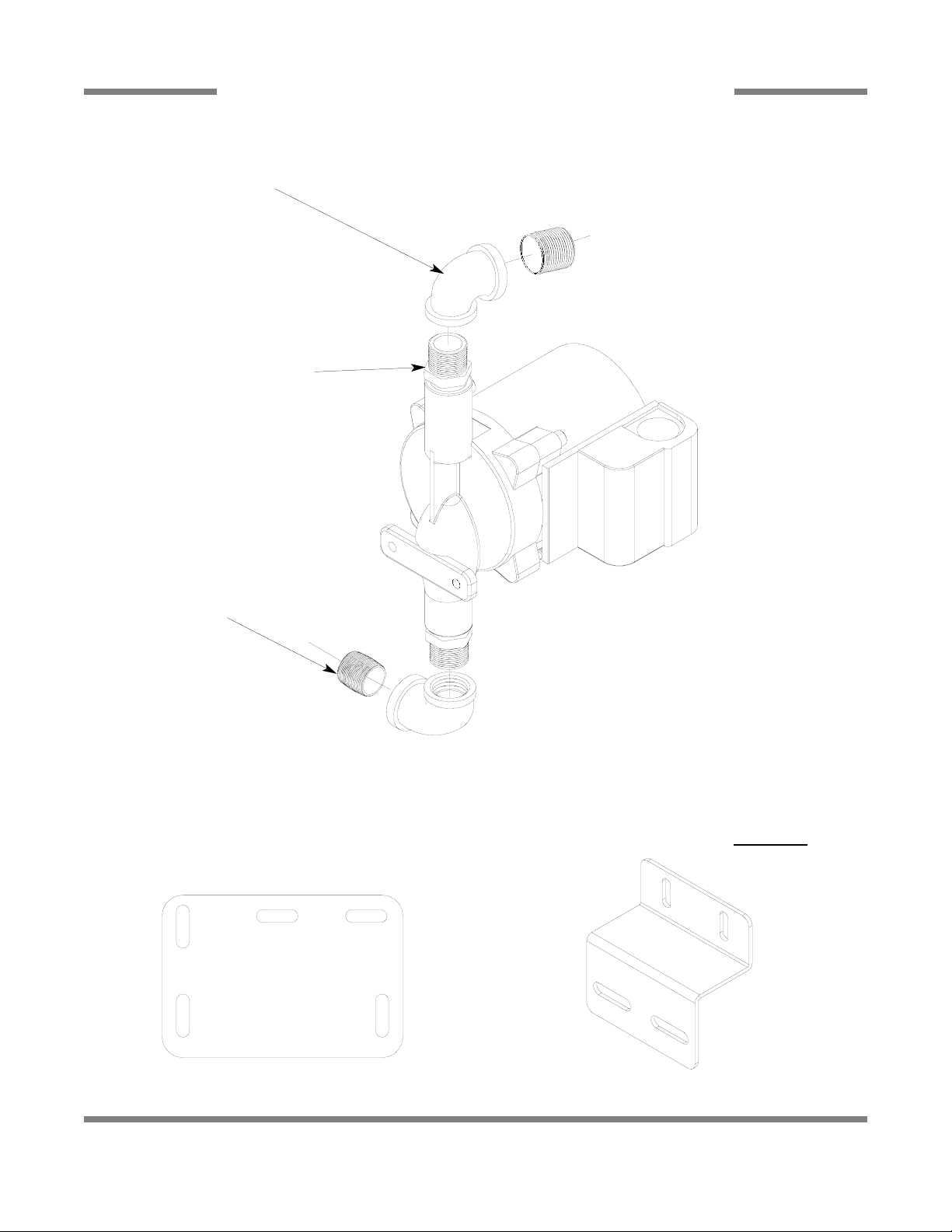
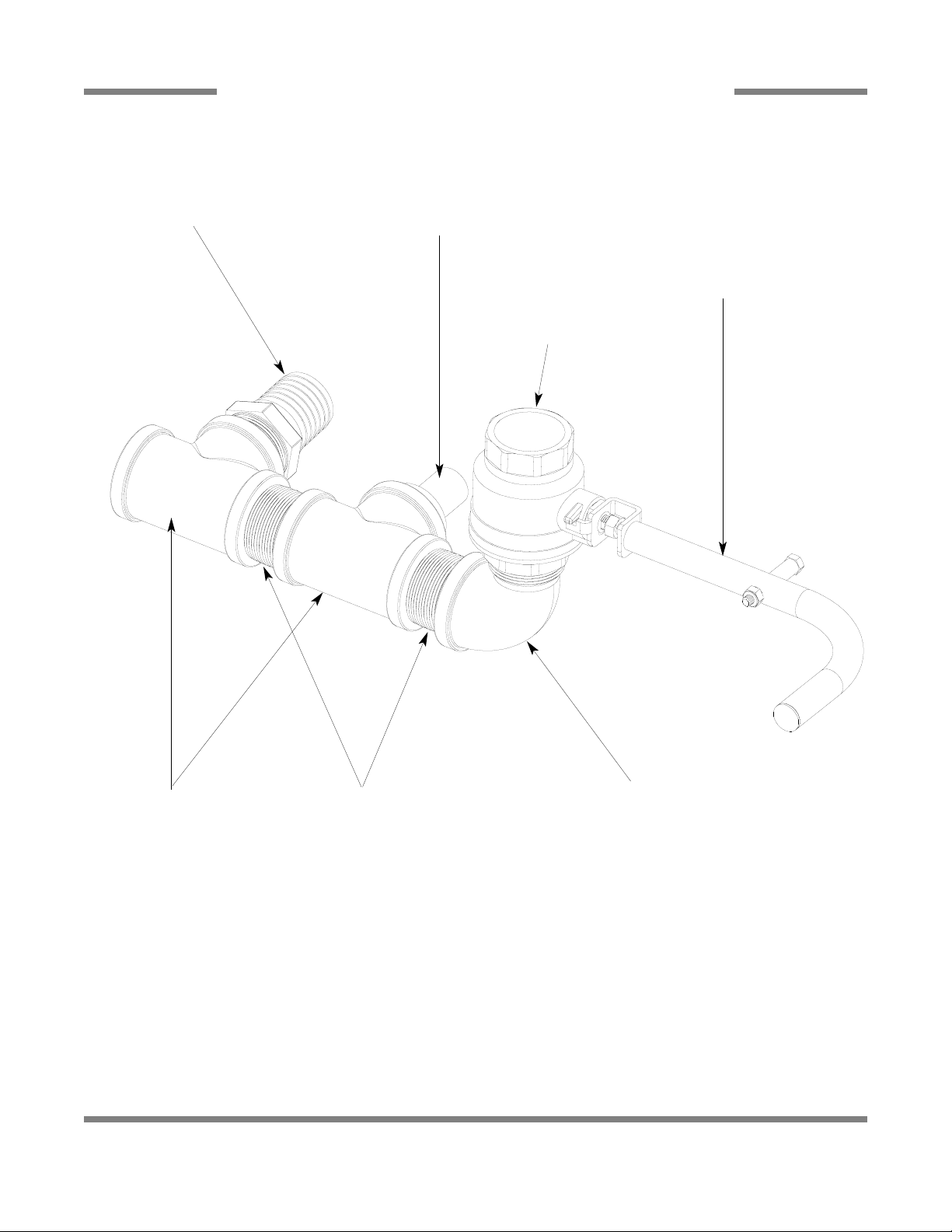
PREWASH PLUMBING ASSEMBLY
70
Y-Strainer, 3/4” NPT,
Brass
04730-717-02-06
Nipple, 3/4”, Brass, Close
04730-207-34-00
Valve, Solenoid, 3/4”
04810-100-53-00
Nipple, 3/4”, Brass, Close
04730-207-34-00
Vacuum Breaker, 3/4”
04820-002-53-77
Elbow, 90°, 3/4” Brass
04730-206-04-34
Elbow, 90°, 3/4” Brass
04730-206-04-34
Nipple, 3/4” x 6” Long
05700-001-26-74
Fill Line Injector Replacement Kit
06401-003-09-93
A new gasket can be
ordered using part number 05330-111-42-81.
Replacement Kit Note:
The kit for the fill line injector comes
with the injector weldment, a new
gasket and the mounting hardware.
PDF compression, OCR, web optimization using a watermarked evaluation copy of CVISION PDFCompressor
Page 11

AJ-44C Series Technical Manual 7610-001-76-22
Issued: 03-21-2006 Revised: N/A
SECTION 5: PARTS SECTION
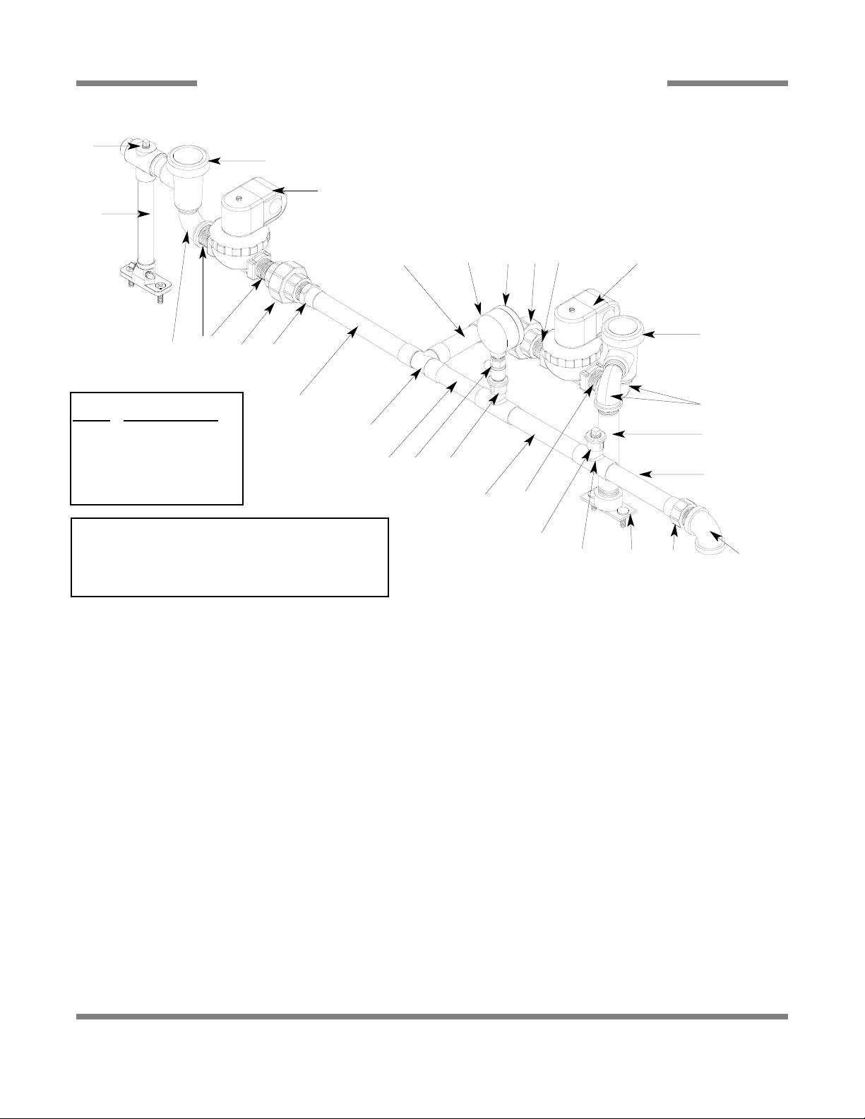
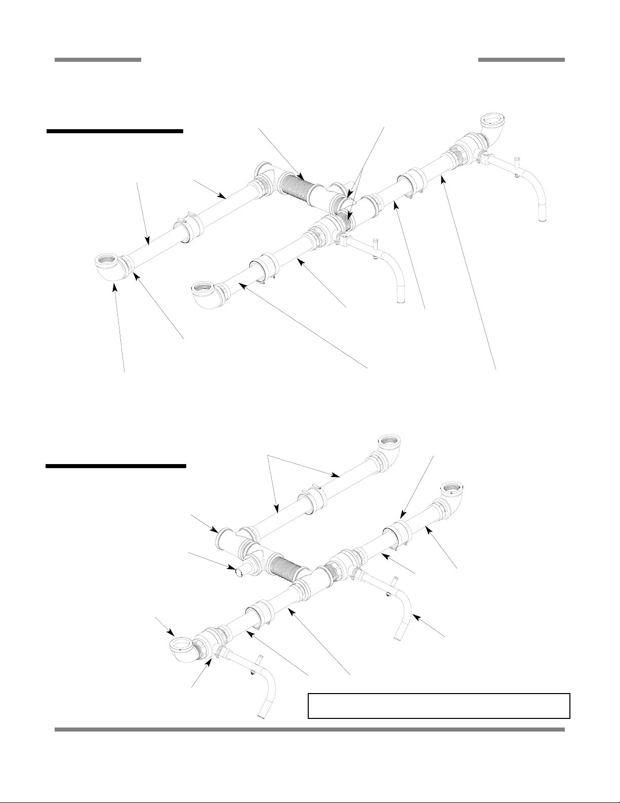
WASH SECTION INCOMING PLUMBING ASSEMBLY
71
ITEM QTY DESCRIPTION Mfg. No.
1 1 Rinse Injector Replacement Kit 06401-003-11-88
1 Gasket 05330-111-42-81
2 3 Plug, Brass, 1/8” NPT 04730-209-07-37
3 2 Vacuum Breaker, 3/4” NPT 04820-002-53-77
4 3 Elbow, Street, 3/4” NPT 04730-206-04-34
5 1 Plug 04730-209-01-00
6 2 Union, Brass, 3/4” 04730-212-05-00
7 2 Solenoid Valve, 3/4” 04810-100-53-00
8 4 Nipple, Close, Brass, 3/4” NPT 04730-207-34-00
9 2 Fitting, 3/4” Male to Slip Copper 04730-401-11-01
10 1 Tube, Copper See Chart
11 1 Fill Injector Replacement Kit 06401-003-09-93
1 Gasket 05330-111-42-81
12 1 Tube, Copper See Chart
13 1 Gauge, Pressure, 0-100 PSI 06685-111-88-34
14 1 Valve, Ball, Test Cock, 1/4” NPT 04810-011-72-67
15 1 Tube, Copper See Chart
16 2 Tee, 3/4” x 3/4” x 1/2” 04730-411-03-01
17 1 Elbow, Brass, 90°, 3/4” Copper 04730-406-42-01
18 2 Tube, Copper See Chart
19 1 Regulator, Pressure, 3/4” NPT, Brass 06685-011-58-22
20 1 Nipple, Brass, 6” Long 05700-001-26-74
21 1 Tee, 3/4”, CU x CU x CU 04730-411-46-01
22 2 Fitting, Adapter, 1/2” to 1/4” 04730-401-41-01
1
3
2
4
20
4
7
7
6 8
8
15
17
8
6 9
10 21 12 162218 5, 16
22
13, 14
19
11 18 9
Left to right direction shown
Tube Length Chart
Item Length (Inches)
10 3/4” x 3-7/16”
12 3/4” x 2-5/8”
15 3/4” x 3”
18 3/4” x 2-13/16”
Replacment Kits Notes:
The rinse and fill injector
replacement kits come with
the injectors, gasket and
mounting hardware. The
rinse injector kit (item 1)
also has the (3) required
brass plugs.
PDF compression, OCR, web optimization using a watermarked evaluation copy of CVISION PDFCompressor
Page 12

AJ-44C Series Technical Manual 7610-001-76-22
Issued: 03-21-2006 Revised: N/A
SECTION 5: PARTS SECTION
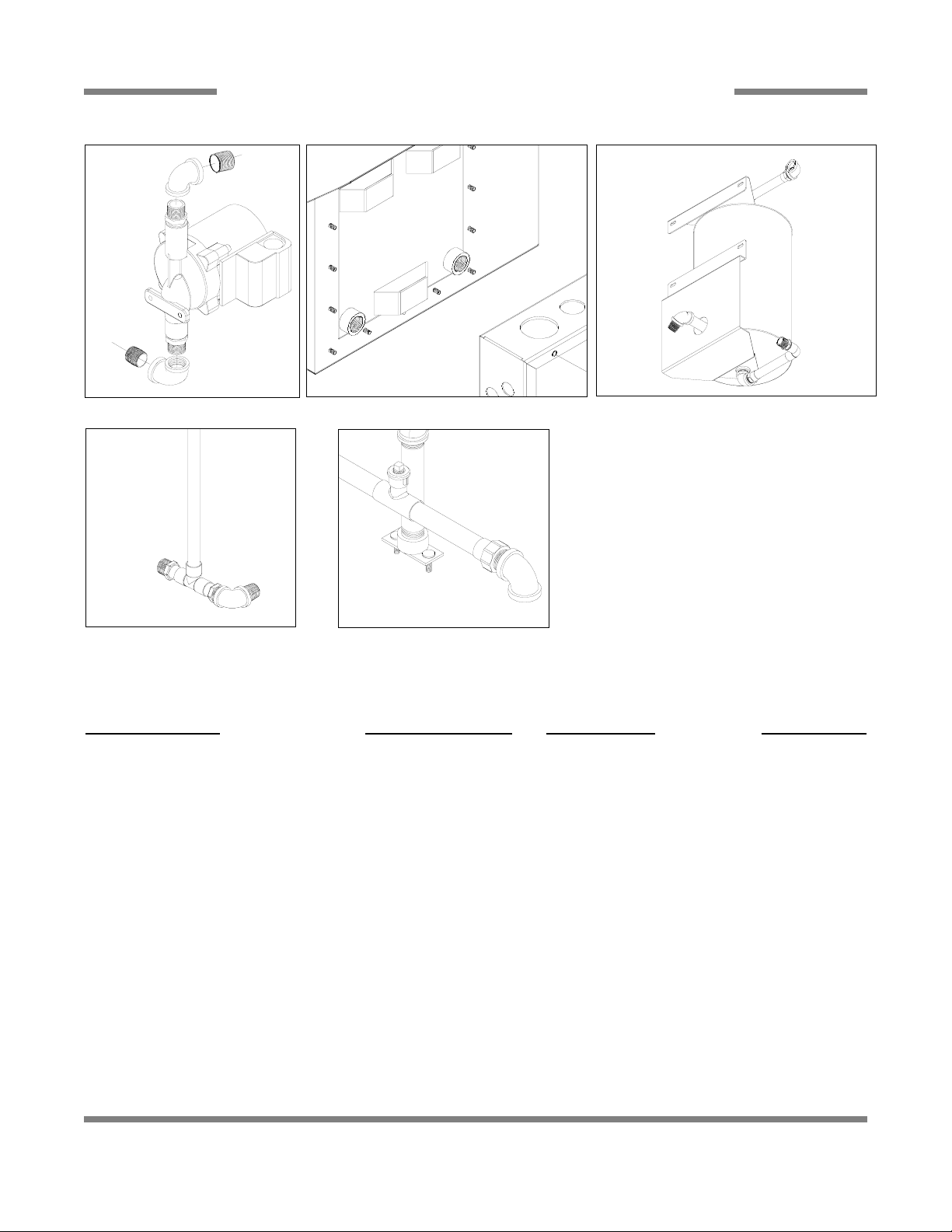
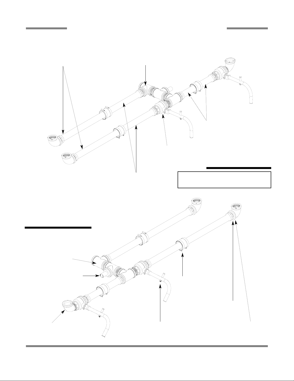
EXTERNAL ELECTRIC BOOSTER INCOMING PLUMBING ASSEMBLIES
72
ITEM QTY DESCRIPTION Mfg. No.
1 - Y-Strainer, 3/4” NPT, Brass 04730-717-02-06
2 - Arrestor, Water Hammer, 1/2” NPT 06685-100-05-00
3 - Regulator, Pressure, 3/4” NPT, Brass 06685-011-58-22
4 - Nipple, 3/4” NPT x 2” Long, Brass 04730-207-46-00
5 - Elbow, Brass, 90°, 3/4” 04730-206-13-00
6 - Nipple, 3/4” NPT, Close, Brass 04730-207-34-00
7 - Coupling, 3/4” FNPT x 3/4” FNPT, Brass 04730-011-87-95
8 - Adapter, 3/4” Male 04730-401-11-01
9 - Tube, Copper See Chart
10 - Adapter, 1/2” NPT x Male 04730-401-07-01
11 - Tee, Copper, 3/4” x 3/4” x 1/2” 04730-411-03-01
1
8
9
11
9
8
2
10
3
4
5
6
7
1
3
4
7
5
6
Plumbing with Water Hammer Arrestor
Plumbing without Water Hammer Arrestor
6
Tube Length Chart
Item #
Length (Inches)
9 3/4” x 3-7/16”
PDF compression, OCR, web optimization using a watermarked evaluation copy of CVISION PDFCompressor
Page 13

AJ-44C Series Technical Manual 7610-001-76-22
Issued: 03-21-2006 Revised: N/A
SECTION 5: PARTS SECTION
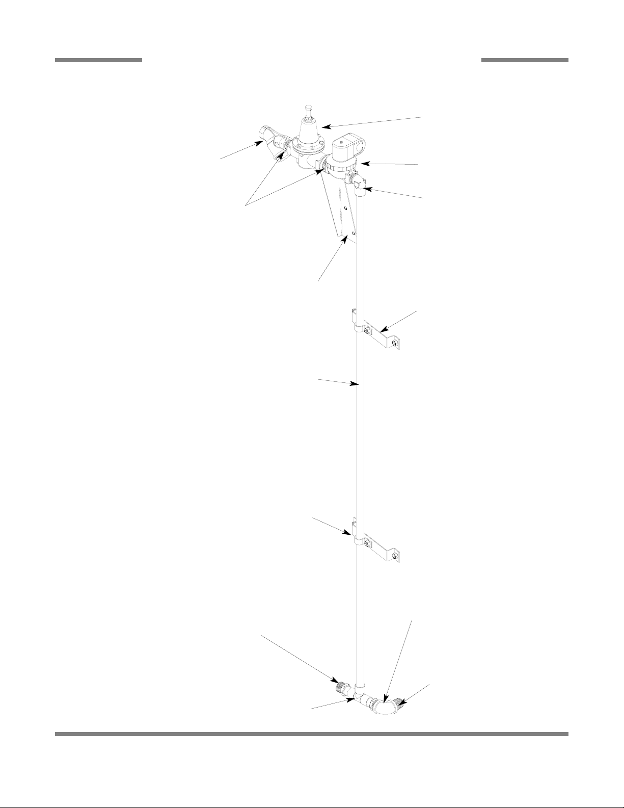
EXTERNAL ELECTRIC BOOSTER OPTION OUTLET PLUMBING
73
Elbow, Brass, 90°, 3/4”
04730-206-13-00
Nipple, 3/4” NPT x 2” Long, Brass
04730-207-46-00
Union, 3/4” NPT, Brass
04730-212-05-00
Adapter, 3/4”, Brass
04730-401-11-01
Tube, Copper, 3/4” x 24” Long
Elbow, 3/4” Copper to Copper (Female)
04730-406-16-01
Tube, Copper, 3/4” x 49-1/2” Long
Elbow, 3/4” Copper to Copper (Female)
04730-406-16-01
Elbow, 3/4”, 90°, Street, Copper to Copper
04730-406-40-01
Tube, Copper, 3/4” x 5-7/8” Long
PDF compression, OCR, web optimization using a watermarked evaluation copy of CVISION PDFCompressor
Page 14

AJ-44C Series Technical Manual 7610-001-76-22
Issued: 03-21-2006 Revised: N/A
SECTION 5: PARTS SECTION
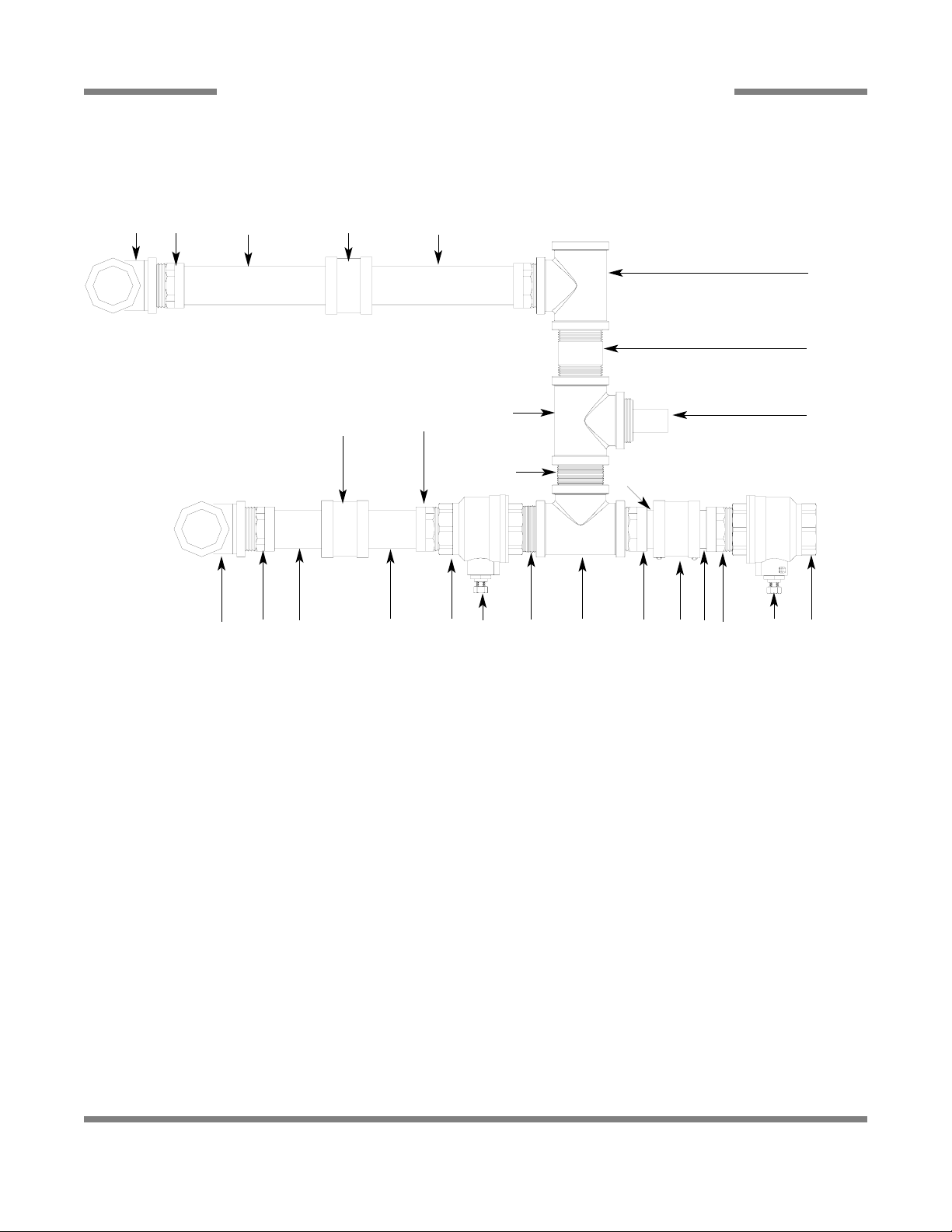
WATER HAMMER ARRESTOR OPTION/WATER PRESSURE REGULATOR KIT OPTION
74
Nipple, 3/4” NPT,
Close, Brass
04730-207-34-00
Water Arrestor, 1/2” NPT
06685-100-05-00
Tee, 3/4” x 3/4” x 1/2”
04730-211-06-00
Water Arrestor, 1/2” NPT
06685-100-05-00
Bushing, 3/4” x 1/2”
04730-002-01-34
Tee, Brass, 3/4” x 3/4” x 3/4”
04730-211-01-34
Nipple, Close, 3/4”
04730-207-34-00
Regulator, Pressure, 3/4”
06685-011-58-22
WATER PRESSURE REGULATOR WITH ARRESTOR KIT OPTION
WATER HAMMER ARRESTOR OPTION
PDF compression, OCR, web optimization using a watermarked evaluation copy of CVISION PDFCompressor
Page 15
AJ-44C Series Technical Manual 7610-001-76-22
Issued: 03-21-2006 Revised: N/A
SECTION 5: PARTS SECTION
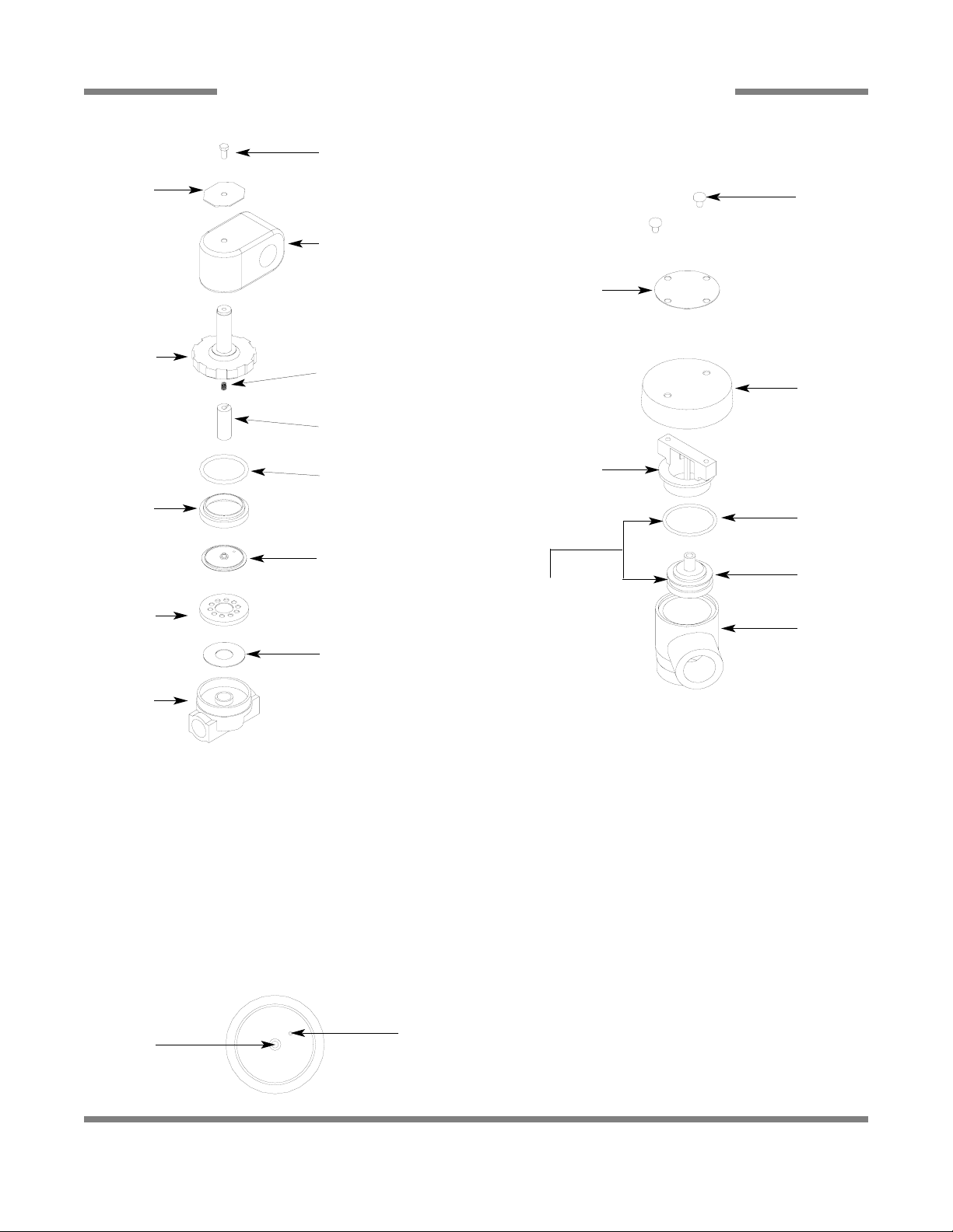
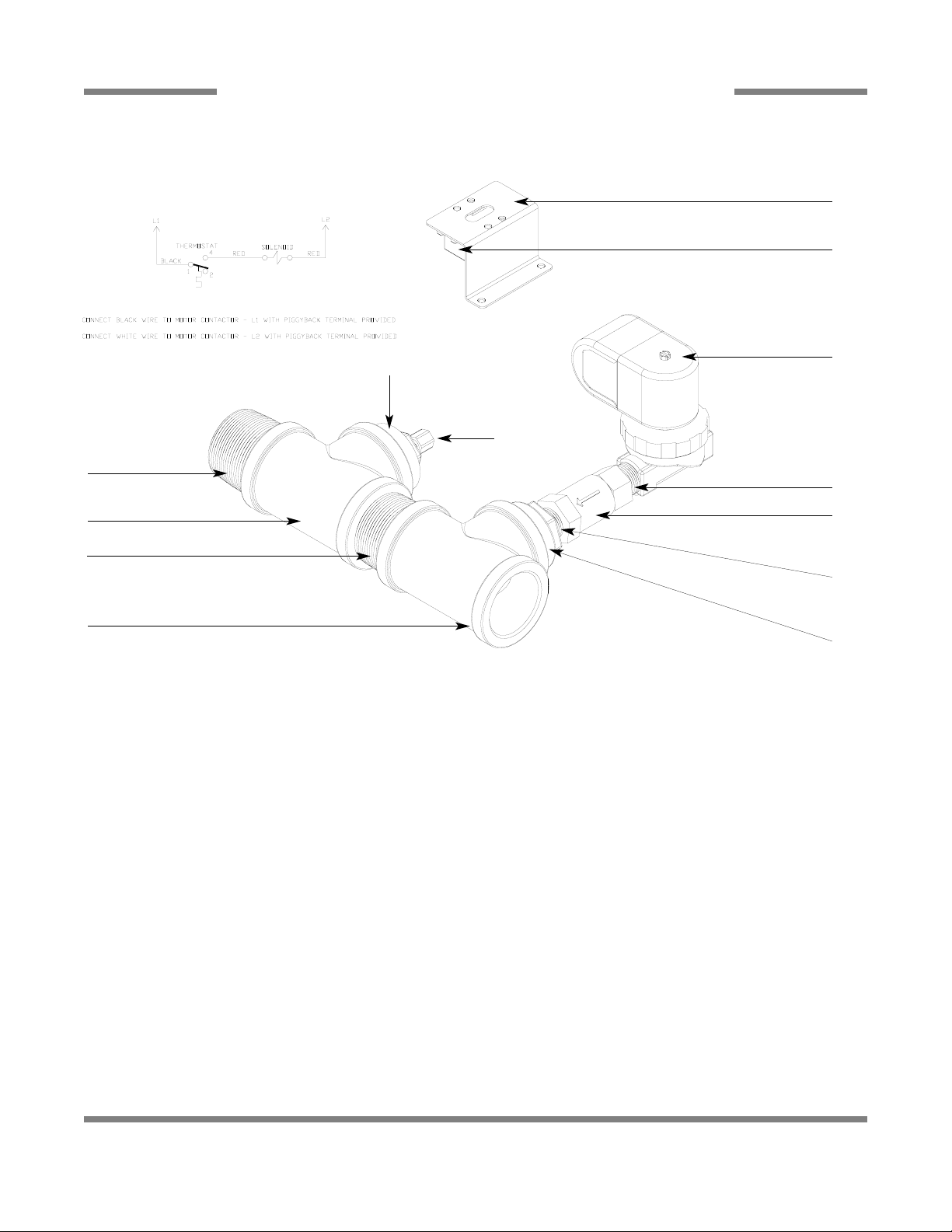
RINSE SOLENOID VALVE & VACUUM BREAKER REPAIR PARTS KITS
75
Complete 110 Volt Solenoid Valve Assembly, 3/4”
04810-100-53-00
Coil & Housing only, 3/4”
06401-003-07-43
Possible Problems:
1. Pilot port extension #1 clogged. Clean hole.
2. Hole #2 Clogged. Pass heated straight pin through hole.
DISASSEMBLY - These valves may be taken apart by
unscrewing the bonnet and the enclosing tube assembly from
the valve body assembly . After unscrewing, carefully lift off the
bonnet and enclosing tube assembly. Don’t drop the plunger.
The o-ring seal and diaphragm cartridge can now be lifted out.
Be careful not to damage the machined faces while the valve
is apart.
TO REASSEMBLE - Place the diaphragm cartridge in the
body with the pilot port extension UP. Hold the plunger with
the synthetic seat against the pilot port. Make sure the o-ring
is in place, then lower the bonnet and enclosing tube assembly over the plunger. Screw the bonnet assembly snugly down
on the body assembly.
Screw
Data Plate
Coil & Housing
Valve Bonnet
Spring
06401-003-07-40
Plunger
06401-003-07-40
Spring position is moved
for clarity.
Goes below the plunger.
O-Ring
06401-003-07-42
Diaphragm
Retainer
Diaphragm
06401-003-07-42
Screen
Retainer
Mesh Screen
Valve Body
Components of
Repair Kit
04820-001-60-57
Cap Screw
Data Plate
Cap
O-Ring
Plunger
Body
Cap Retainer
1
2
Complete Vacuum Breaker Assembly, 3/4” NPT
04820-002-53-77
PDF compression, OCR, web optimization using a watermarked evaluation copy of CVISION PDFCompressor
Page 16

AJ-44C Series Technical Manual 7610-001-76-22
Issued: 03-21-2006 Revised: N/A
SECTION 5: PARTS SECTION
STEAM UNIT WASH TANK COIL ASSEMBLY
76
Coil Weldment
05700-002-84-03
Stand “C” Weldment
05700-002-74-84
Stand “D” Weldment
05700-002-74-85
Coil Nut
05310-011-17-85
Flat Washer
05700-001-17-87
Coil Gasket
05700-001-17-86
SERVICE NOTE: Jackson
HIGHLY recommends that the
Coil Gaskets be replaced any
time the Coil Weldment is
replaced or removed for an
extended period of time.
Stand “B” Weldment
05700-002-74-83
PDF compression, OCR, web optimization using a watermarked evaluation copy of CVISION PDFCompressor
Page 17
AJ-44C Series Technical Manual 7610-001-76-22
Issued: 03-21-2006 Revised: N/A
SECTION 5: PARTS SECTION
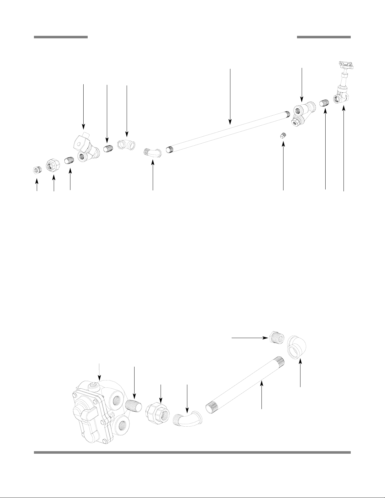
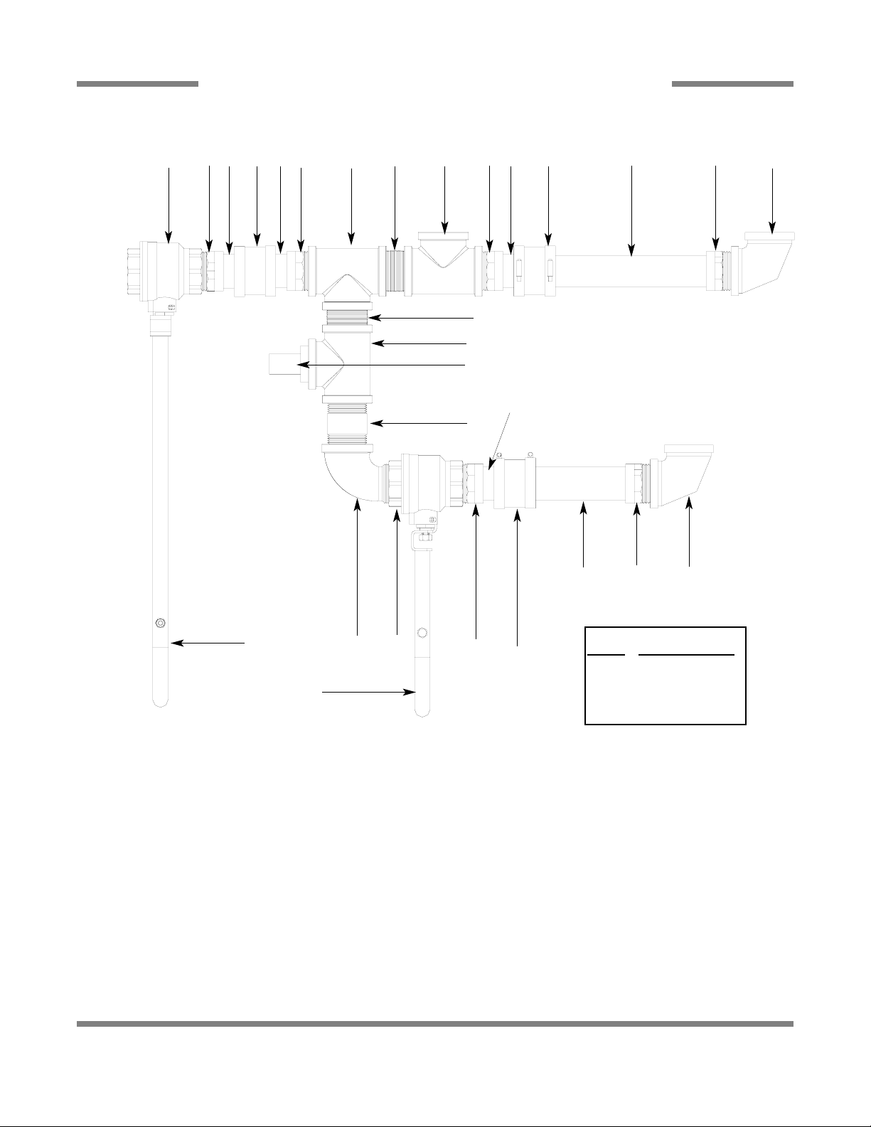
STEAM PLUMBING (LEFT TO RIGHT)
77
ITEM QTY DESCRIPTION Mfg. No.
1 1 Reducer, 3/4” NPT to 1/2” NPT, Black Iron 04730-911-02-34
2 1 Union, 3/4” NPT, Black Iron 04730-912-01-00
3 3 Nipple, Close, 3/4” NPT, Black Iron 04730-907-01-00
4 1 Valve, Steam Solenoid, 3/4” NPT, 120V 04820-011-87-39
5 1 Elbow, 90°, 3/4” FNPT, Black Iron 04730-906-10-34
6 1 Elbow, Street, 90°, 3/4” NPT, Black Iron 04730-011-87-37
7 1 Y-Strainer, 3/4” NPT, Black Iron 04730-217-01-32
8 1 Valve, Gate, Steam, 3/4” NPT 04820-100-19-00
9 1 Plug, 3/8” NPT, Black Iron 04730-909-02-34
10 1 Nipple, 3/4” NPT x 32” Long 04730-002-21-27
11 1 Reducer, 3/4” NPT to 1/2” NPT, Black Iron 04730-911-02-34
12 1 Elbow, 90°, 3/4” FNPT, Black Iron 04730-906-10-34
13 1 Elbow, Street, 3/4” NPT, Black Iron 04730-011-87-37
14 1 Union, 3/4” NPT, Black Iron 04730-912-01-00
15 1 Nipple, Close, 3/4” NPT, Black Iron 04730-907-01-00
16 1 Steam Trap, 3/4” NPT 06680-500-02-77
17 1 Pipe, 3/4” NPT x 10” Long, Black Iron 04730-907-06-34
1
2
3 6
4
3 5
10
9
7
3
8
11
12
17
1314
15
16
STEAM INLET PLUMBING
STEAM OUTLET PLUMBING
PDF compression, OCR, web optimization using a watermarked evaluation copy of CVISION PDFCompressor
Page 18
AJ-44C Series Technical Manual 7610-001-76-22
Issued: 03-21-2006 Revised: N/A
SECTION 5: PARTS SECTION
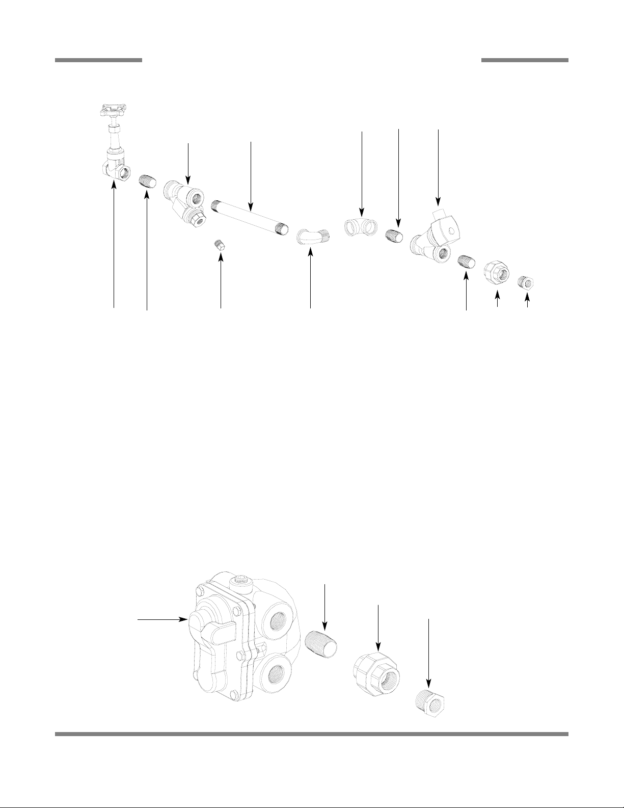
STEAM PLUMBING (RIGHT TO LEFT)
78
ITEM QTY DESCRIPTION Mfg. No.
1 1 Reducer, 3/4” NPT to 1/2” NPT, Black Iron 04730-911-02-34
2 1 Union, 3/4” NPT, Black Iron 04730-912-01-00
3 3 Nipple, Close, 3/4” NPT, Black Iron 04730-907-01-00
4 1 Valve, Steam Solenoid, 3/4” NPT, 120V 04820-011-87-39
5 1 Elbow, 90°, 3/4” FNPT, Black Iron 04730-906-10-34
6 1 Elbow, Street, 90°, 3/4” NPT, Black Iron 04730-011-87-37
7 1 Y-Strainer, 3/4” NPT, Black Iron 04730-217-01-32
8 1 Valve, Gate, Steam, 3/4” NPT 04820-100-19-00
9 1 Plug, 3/8” NPT, Black Iron 04730-909-02-34
10 1 Nipple, 3/4” NPT x 10” Long 04730-907-06-34
11 1 Reducer, 3/4” NPT to 1/2” NPT, Black Iron 04730-911-02-34
12 1 Elbow, 90°, 3/4” FNPT, Black Iron 04730-906-10-34
13 1 Elbow, Street, 3/4” NPT, Black Iron 04730-011-87-37
14 1 Union, 3/4” NPT, Black Iron 04730-912-01-00
15 1 Nipple, Close, 3/4” NPT, Black Iron 04730-907-01-00
16 1 Steam Trap, 3/4” NPT 06680-500-02-77
17 1 Pipe, 3/4” NPT x 10” Long, Black Iron 04730-907-06-34
8 9 63
7
10
5 3
3
4
1
2
17
13
14
16
STEAM INLET PLUMBING
STEAM OUTLET PLUMBING
PDF compression, OCR, web optimization using a watermarked evaluation copy of CVISION PDFCompressor
Page 19

AJ-44C Series Technical Manual 7610-001-76-22
Issued: 03-21-2006 Revised: N/A
SECTION 5: PARTS SECTION
GAS COIL ASSEMBLY (CGP MODELS)
79
Other items used but not shown.
ITEM QTY DESCRIPTION Mfg. No.
1 1 Thermostat, High Limit 05930-011-49-43
2 1 Terminal Board 05940-002-78-97
3 1 Thermostat Bracket 05700-011-81-64
4 1 Decal, Thermostat Regulating 09905-011-84-31
5 1 Thermostat, Wash Regulating 06401-140-00-32
6 2 Fitting, 1/4”, Imperial Brass 05310-924-02-05
Gas Coil Weldment
05700-002-44-23
Connection point for:
Hose, Recirculating Discharge
(See “Hose Connections” page )
Connects with:
3/4” 90° Elbow Brass
04730-206-13-00
3/4” Close Brass Nipple
04730-207-34-00
Connection point for:
Hose, Wash Coil Assembly
(See “Hose Connections” page )
Connects with:
3/4” 90° Elbow Brass
04730-206-13-00
3/4” Close Brass Nipple
04730-207-34-00
Coil Box Weldment
05700-002-50-94
Gas Coil Box Cover
Replacement Kit
06401-003-10-37
PDF compression, OCR, web optimization using a watermarked evaluation copy of CVISION PDFCompressor
Page 20
AJ-44C Series Technical Manual 7610-001-76-22
Issued: 03-21-2006 Revised: N/A
SECTION 5: PARTS SECTION
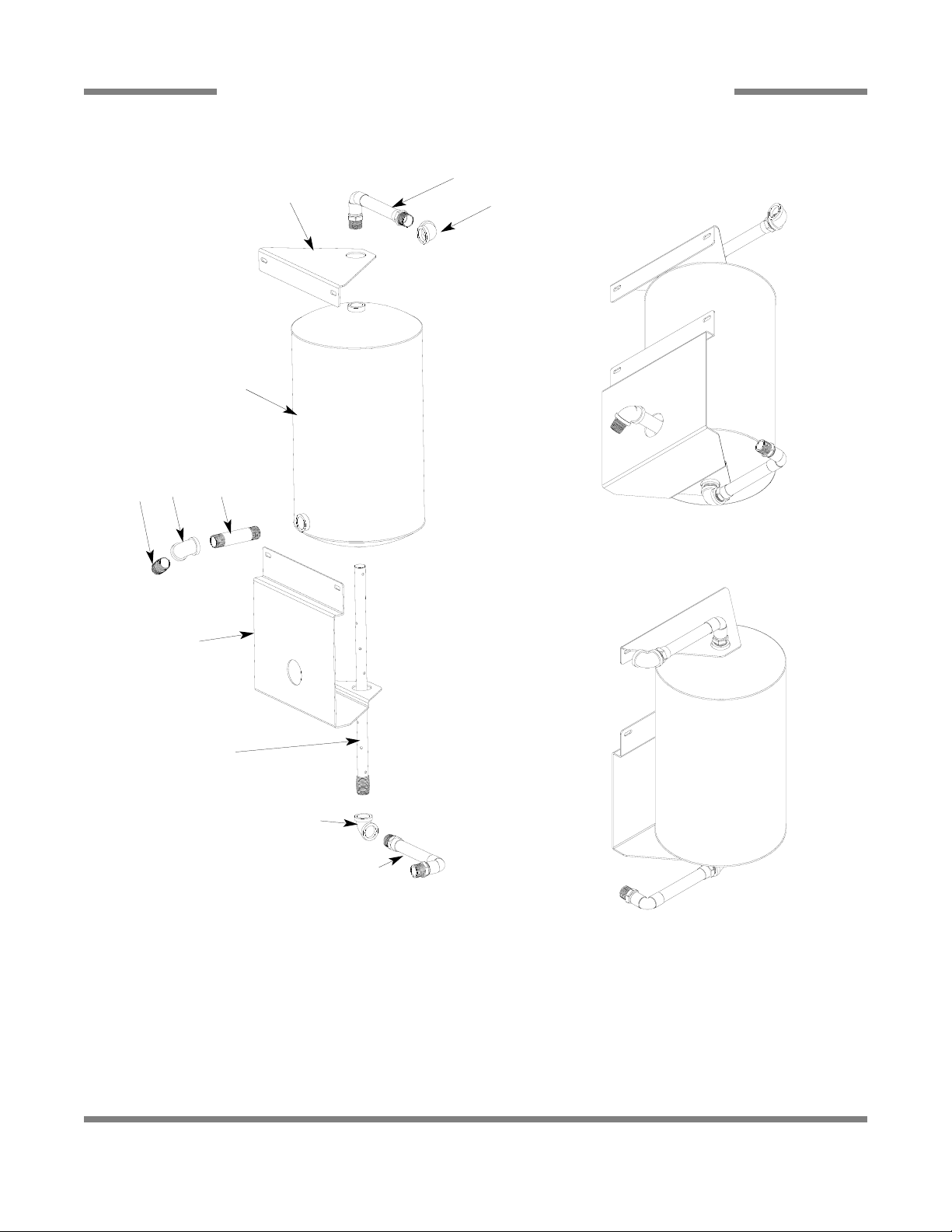
TANK, RINSE BOOSTER (CGP MODELS ONLY)
80
BOTTOM ANGLED VIEW
TOP ANGLED VIEW
ITEM QTY DESCRIPTION Mfg. No.
1 2 Plumbing Assembly, Inlet/Discharge, Rinse Tank 05700-002-51-24
2 1 Tube, Dispersion Weldment 05700-002-46-16
3 1 Tank, GP Rinse 05700-002-45-05
4 1 Bracket, Upper Rinse Tank 05700-002-67-13
5 1 Bracket, Lower Rinse Tank 05700-002-67-14
6 1 Nipple, 3/4” NPT x 4” Long 04730-207-05-00
7 3 Elbow, 3/4” NPT, 90° Brass 04730-206-13-00
8 1 Nipple, 3/4” NPT x Closed Brass 04730-207-34-00
1
7
4
8
7
6
6
2
7
1
6
PDF compression, OCR, web optimization using a watermarked evaluation copy of CVISION PDFCompressor
Page 21
AJ-44C Series Technical Manual 7610-001-76-22
Issued: 03-21-2006 Revised: N/A
SECTION 5: PARTS SECTION
RECIRCULATING PUMP ASSEMBLY (CGP MODELS ONLY)
81
Nipple, 3/4” Close Brass
2 per
04730-207-34-00
Elbow, 3/4” 90° Brass
2 per
04730-206-13-00
Pump, Recirculating with Adapters
05700-002-51-28
Mounting Bracket
05700-002-25-74
Mounting Bracket
05700-002-23-61
Used only on AJ-66CGP/AJ-80CGP left to right units.
Used on AJ-44CGP, AJ-66CGP, AJ-80CGP units right to
left units and the AJ-44CGP left to right unit.
PDF compression, OCR, web optimization using a watermarked evaluation copy of CVISION PDFCompressor
Page 22
AJ-44C Series Technical Manual 7610-001-76-22
Issued: 03-21-2006 Revised: N/A
SECTION 5: PARTS SECTION
HOSE CONNECTIONS (CGP MODELS ONLY)
82
HOSE ASSEMBLIES
AJ-44CGP (L-R & R-L)
AJ-66CGP (L-R ) AJ-66CGP (R-L)
*Each hose assembly includes 2, 3/4” Pushlock Fittings (part number 04730-011-94-00).
A - Hose, Recirculating Discharge (8 1/2”) 05700-002-52-74 (18”) 05700-002-51-38 (8 1/2”) 05700-002-52-74
B - Hose, Recirculating Pump Suction (18 1/2”) 05700-002-52-75 (26”) 05700-002-51-37 (18 1/2”) 05700-002-52-75
C - Hose, Wash Coil Assembly (34”) 05700-002-52-76 (36”) 05700-002-51-39 (50”) 05700-002-57-58
D - Hose, Recirculating Discharge (L-R 48”) 05700-003-03-95 (60”) 05700-003-03-97 (60”) 05700-003-03-97
(R-L 60”) 05700-003-03-97
E - Hose connection to existing gas booster outlet fitting.
F - Hose connection to existing gas booster inlet fitting.
Gas Booster Connection Kit 05700-002-51-73 includes:
18 Feet of 3/4” Hose
4 - 3/4” Push Lock Fittings
A
B
A
C
C
E
D
Recirculating Pump Assembly
Gas Coil Weldment Rinse Booster Tank
Rinse Header Plumbing Assembly
Wash/Fill Plumbing Assembly
B
F
D
PDF compression, OCR, web optimization using a watermarked evaluation copy of CVISION PDFCompressor
Page 23
AJ-44C Series Technical Manual 7610-001-76-22
Issued: 03-21-2006 Revised: N/A
SECTION 5: PARTS SECTION
WASH/FILL PLUMBING ASSEMBLY (CGP MODELS)
83
1
5
2
3
3
4
19
6
6
7
8
9
18
6
18
5
21
15
20
10
14
11, 12
12, 13
8
22
17
16
11
47
ITEM QTY DESCRIPTION Mfg. No.
1 1 Rinse Injector Weldment Replacement Kit 06401-003-11-84
1 Gasket 05330-111-42-81
2 3 Plug, 1/8” NPT, Brass 04730-209-07-37
3 2 Vacuum Breaker, 3/4” NPT 04820-002-53-77
4 2 Valve, Solenoid, 3/4” NPT, 110 Volt 04810-100-53-00
5 3 Elbow, 3/4” Street Brass 04730-206-04-34
6 4 Nipple, Close, Brass, 3/4” NPT 04730-207-34-00
7 4 Union, 3/4”, Copper to Copper 04730-212-05-00
8 2 Adapter, 3/4” Fitting x Male 04730-401-11-01
9 1 Elbow, 90° 3/4” Copper to MSPS 04730-406-42-01
10 1 Tee, 3/4”, CU x CU x CU 04730-411-46-01
11 2 Tee, 3/4” x 3/4” x 1/2” 04730-411-03-01
12 2 Fitting, Adapter, 1/2” to 1/4” 04730-401-41-01
13 1 Plug, 1/4” NPT, Brass 04730-209-01-00
14 1 Test Cock, Valve, Ball, 1/4” NPT 04810-011-72-67
15 1 Gauge, Pressure, 0-100 PSI 06685-111-88-34
16 1 Nipple, Brass, 6” Long 05700-001-26-74
17 1 Fill Injector Replacement Kit 06401-003-09-93
1 Gasket 05330-111-42-81
18 1 Tube, Copper See Chart
19 1 Tube, Copper See Chart
20 1 Tube, Copper See Chart
21 1 Tube, Copper See Chart
22 1 Elbow, 3/4” NPT, 90° Brass 04730-206-13-00
Tube Length Chart
Item #
Length (Inches)
18 3/4” x 2-13/16”
19 3/4” x 3-7/16”
20 3/4” x 3”
21 3/4” x 2-5/8”
Replacement Kits Notes:
The rinse injector and fill injector replacement kits come
with the injector weldments, the gaskets and hardware
for mounting. In the case of Item (1) below, it also comes
with the required (3) brass plugs.
PDF compression, OCR, web optimization using a watermarked evaluation copy of CVISION PDFCompressor
Page 24
AJ-44C Series Technical Manual 7610-001-76-22
Issued: 03-21-2006 Revised: N/A
SECTION 5: PARTS SECTION
RINSE HEADER PLUMBING ASSEMBLY (CGP MODELS)
84
Copper Tube
3/4” x 56” Long
Incoming Plumbing Support Bracket
05700-002-50-70
Nipple, 3/4” Close Brass
04730-207-34-00
Solenoid Valve, 3/4” 110V
04810-100-53-00
Valve, 3/4” Pressure Reducing
04820-002-51-53
Y-Strainer, 3/4” Brass
04730-717-02-06
Inlet Plumbing Mounting Bracket
2 per
05700-002-51-41
Clamp, Pipe
2 per
05700-000-35-06
Elbow, 3/4” NPT 90° Brass
04730-206-13-00
Nipple, 3/4” Close Brass
04730-207-34-00
Adapter, 3/4”
04730-401-10-01
Tee, 3/4” x 3/4” x 3/4”
04730-411-46-01
Elbow, 3/4” Slip x 3/4” NPT
04730-406-42-01
PDF compression, OCR, web optimization using a watermarked evaluation copy of CVISION PDFCompressor
Page 25
AJ-44C Series Technical Manual 7610-001-76-22
Issued: 03-21-2006 Revised: N/A
SECTION 5: PARTS SECTION
AJ-44 SERIES DRAIN PLUMBING ASSEMBLIES
85
AJ-44 Series Ball Valve Handle Assembly
06401-021-83-53
AJ-44CGP Ball Valve Handle Assembly
06401-021-84-74
Ball Valve, 1-1/2” NPT
04820-111-71-46
Elbow, 1-1/2” Brass 90° Street
04730-206-32-00
Nipple, 1-1/2” Brass, Close
04730-207-40-00
Tee, 1-1/2” Brass
04730-011-69-93
Nipple, Rinse Weldment
05700-021-84-61
Fitting, Barbed, 1-1/2” NPT x 1-1/2”
04730-011-69-92
PDF compression, OCR, web optimization using a watermarked evaluation copy of CVISION PDFCompressor
Page 26
AJ-44C Series Technical Manual 7610-001-76-22
Issued: 03-21-2006 Revised: N/A
SECTION 5: PARTS SECTION
AJ-66 DRAIN PLUMBING ASSEMBLIES
86
Tube, Copper, 1-1/2” x 8-1/4” Long
Adapter, Male to Female, 1-1/2”
04730-401-25-01
Elbow, 1-1/2” FNPT, 90°, Brass
04730-011-73-77
Tube, Copper, 1-1/2” x 4-3/4” Long
Tube, Copper, 1-1/2” x 4-1/4” Long
Left to Right Plumbing
Assembly
Connector, No-Hub, 1-1/2”
04720-604-06-00
Valve, Ball, 1-1/2”
04820-111-71-46
Ball Valve Handle Assembly
06401-021-84-74
Nipple, Brass, Close, 1-1/2” NPT
04730-207-40-00
Nipple, Brass, Close, 3” NPT
04730-011-87-04
Tee, Brass, 1-1/2” x 1-1/2” x 1-1/2”
04730-011-69-93
Tube, Copper, 1-1/2” x 8-1/4” Long
Tube, Copper, 1-1/2” x 4-3/4” Long
Tube, Copper, 1-1/2” x 4-1/4” Long
Nipple, Rinse Weldment
05700-021-84-61
Elbow, Brass, Street, 1-1/2” NPT
04730-206-32-00
Right to Left Plumbing
Assembly
All parts are common to both assemblies.
Service Note: Copper tubing should be purchased locally and
cut to length (lengths provided in drawings).
PDF compression, OCR, web optimization using a watermarked evaluation copy of CVISION PDFCompressor
Page 27
AJ-44C Series Technical Manual 7610-001-76-22
Issued: 03-21-2006 Revised: N/A
SECTION 5: PARTS SECTION
AJ-80 DRAIN PLUMBING ASSEMBLIES
87
Tube, Copper, 1-1/2” x 15-3/16” Long
Tube, Copper, 1-1/2” x 11-3/16” Long
Valve, Ball, 1-1/2”
04820-111-71-46
Tube, Copper, 1-1/2” x 4-15/16” Long
Left to Right Plumbing
Assembly
Adapter, Male to Female, 1-1/2”
04730-401-25-01
Elbow, 1-1/2” FNPT, 90°, Brass
04730-011-73-77
Connector, No-Hub, 1-1/2”
04720-604-06-00
Ball Valve Handle Assembly
06401-021-84-74
Nipple, Brass, Close, 1-1/2” NPT
04730-207-40-00
Tee, Brass, 1-1/2” x 1-1/2” x 1-1/2”
04730-011-69-93
Nipple, Rinse Weldment
05700-021-84-61
Elbow, Brass, Street, 1-1/2” NPT
04730-206-32-00
Right to Left Plumbing
Assembly
Assemblies are mirrored and all parts are common to both assemblies.
Service Note: Copper tubing should be purchased locally and cut to length (lengths provided in drawings).
PDF compression, OCR, web optimization using a watermarked evaluation copy of CVISION PDFCompressor
Page 28
AJ-44C Series Technical Manual 7610-001-76-22
Issued: 03-21-2006 Revised: N/A
SECTION 5: PARTS SECTION
AJ-66CGP (LEFT TO RIGHT) DRAIN PLUMBING ASSEMBLY
88
ITEM QTY DESCRIPTION Mfg. No.
1 6 Adapter, Male to Female, 1-1/2” 04730-401-25-01
2 3 No-Hub Connector 04720-604-06-00
3 3 Tee, Brass, 1-1/2” FNPT 04730-011-69-93
4 2 Ball Valve, 1-1/2” FNPT 04820-011-71-46
* 2 Valve Handle Weldment Assembly (Not Shown) 06401-021-84-74
5 2 Nipple, Brass, Close, 1-1/2” NPT 04730-207-40-00
6 2 Elbow, Brass, 90°, 1-1/2” FNPT 04730-011-73-77
7 2 Tube, Copper, 1-1/2” x 1-3/4” Long See Service
Note
8 1 Rinse Nipple Weldment 05700-021-84-61
9 2 Tube, Copper, 1-1/2” x 3-1/2” Long See Service
Note
10 2 Tube, Copper, 1-1/2” x 7-1/2” Long See Service
Note
11 1 Nipple, Brass, 1-1/2” NPT x 3” Long 04730-011-87-04
Service Note: Copper tubing should be purchased locally and cut to length (lengths provided in parts list above).
6
6
5 2
2
1
3
4*
8
5
9
9
4*
3 1
2
1
1
10
11
137
10
13
3
5
7
PDF compression, OCR, web optimization using a watermarked evaluation copy of CVISION PDFCompressor
Page 29
AJ-44C Series Technical Manual 7610-001-76-22
Issued: 03-21-2006 Revised: N/A
SECTION 5: PARTS SECTION
AJ-66CGP (RIGHT TO LEFT) DRAIN PLUMBING ASSEMBLY
89
ITEM QTY DESCRIPTION Mfg. No.
1 1 Elbow, 1-1/2” NPT, Brass, Street 04730-206-32-00
2 2 Valve, Ball, 1-1/2” FNPT 04820-011-71-46
3 6 Adapter, Male to Female, 1-1/2” 04730-401-25-01
4 4 Tube, Copper See Chart
5 3 Tee, Brass, 1-1/2” FNPT 04730-011-69-93
6 2 Nipple, Brass, 1-1/2” NPT, Close 04730-207-40-00
7 2 Tube, Copper See Chart
8 2 Tube, Copper See Chart
9 2 Elbow, Brass, 90°, 1-1/2” FNPT 04730-011-73-77
10 3 No-Hub Connector 04720-604-06-00
11 1 Nipple, Brass, 1-1/2” NPT x 3” Long 04730-011-87-04
12 1 Rinse Nipple Weldment 05700-021-84-61
13 1 Valve Handle Weldment Assembly 06401-021-84-74
14 1 Valve Handle Weldment Assembly 06401-002-57-83
3
10
4
5
8
7
9
2
5
6
6
3
12
3
10
3
11
4
3
1
9
5
4
4
10
32
14
13
Tube Length Chart
Item #
Length (Inches)
4 1-1/2” x 1-7/8”
7 1-1/2” x 5-3/16”
8 1-1/2” x 8-1/8”
PDF compression, OCR, web optimization using a watermarked evaluation copy of CVISION PDFCompressor
Page 30
AJ-44C Series Technical Manual 7610-001-76-22
Issued: 03-21-2006 Revised: N/A
SECTION 5: PARTS SECTION
DRAIN QUENCH SYSTEM
90
ITEM QTY DESCRIPTION Mfg. No.
1 1 Thermostat 05930-121-67-72
2 1 Thermostat Bracket 05700-022-73-72
3 1 Solenoid Valve 04810-100-09-18
4 2 Nipple, Close, 1/2” NPT, Brass 04730-207-15-00
5 1 Valve, Check, 1/2” 04820-002-55-77
6 1 Reducer, 1-1/2” to 1/2” 04730-002-55-75
7 2 Tee, 1-1/2” x 1-1/2” x 1-1/2” 04730-011-69-93
8 2 Nipple, 1-1/2”, Close, Brass 04730-207-40-00
9 1 Reducer, 1-1/2” to 1/4” 04730-002-55-76
10 1 Modified Compression Fitting 05700-001-16-52
1 Complete Kit 06401-002-44-07
To Dishmachine Drain
To Drain
To Cold Water Supply
Schematic
1
2
3
4
5
4
6
7
8
7
8
9
10
From the existing drain, attach the two additional Tees (Item 7) using the 1-1/2” NPT Close Nipples (Item 8). Tighten the
Reducers (Items 6 & 9) into the Tees as shown above. Attach the Modified Compression Fitting (Item 10) into the 1-1/2” to 1/4”
Reducer (Item 9). Position the bulb of the thermostat (Item 1) so that it rests approximately 1/4” from the bottom of the Tee (Item
7). Tighten the Modified Compression Fitting (Item 10) as required.
Mount the Thermostat (Item 1) to the tub using the Thermostat Bracket (Item 2) and set it for 120
°
F - 140°F. Install the Solenoid
Valve (Item 3) to the second Tee (Item 7) and then attach to the incoming cold water line. Use pipe dope or thread tape as
required to prevent any leaks.
PDF compression, OCR, web optimization using a watermarked evaluation copy of CVISION PDFCompressor
Page 31

AJ-44C Series Technical Manual 7610-001-76-22
Issued: 03-21-2006 Revised: N/A
SECTION 5: PARTS SECTION
MOTOR ASSEMBLIES
91
WASH MOTOR CHART
Volts Phase Hz Motor Part Number Kit Part Number
200 - 440 3 50 06105-121-81-34 06401-003-09-96
208 - 230 1 60 06105-021-70-57 06401-003-09-97
200 - 230 3 60 06105-121-70-58 06401-003-09-98
380 3 60 06105-121-81-34 06401-003-09-96
460 3 60 06105-121-70-58 06401-003-09-98
600 3 60 06105-002-48-31 06401-003-09-99
PREW
ASH MOTOR CHART
Model(s) Volts Phase Hz Part Number Kit Part Number
AJ-66’s 208 3 50 06105-121-70-56 06401-003-10-38
220 3 50 06105-121-70-56 06401-003-10-38
230 3 50 06105-121-70-56 06401-003-10-38
380 3 50 06105-121-81-34 06401-003-10-39
415 3 50 06105-121-81-34 06401-003-10-39
440 3 50 06105-121-70-56 06401-003-10-38
208 1 60 06105-121-70-55 06401-003-10-40
230 1 60 06105-121-70-55 06401-003-10-40
200 3 60 06105-121-70-56 06401-003-10-38
220 3 60 06105-121-70-56 06401-003-10-38
230 3 60 06105-121-70-56 06401-003-10-38
380 3 60 06105-121-70-56 06401-003-10-38
460 3 60 06105-121-70-56 06401-003-10-38
600 3 60 06105-002-48-31 06401-003-10-41
AJ-80’s 208 3 50 06105-121-81-34 06401-003-10-39
220 3 50 06105-121-81-34 06401-003-10-39
230 3 50 06105-121-81-34 06401-003-10-39
380 3 50 06105-121-81-34 06401-003-10-39
415 3 50 06105-121-81-34 06401-003-10-39
440 3 50 06105-121-81-34 06401-003-10-39
208 1 60 06105-121-70-57 06401-003-10-42
230 1 60 06105-121-70-57 06401-003-10-42
200 3 60 06105-121-70-58 06401-003-10-43
220 3 60 06105-121-70-58 06401-003-10-43
230 3 60 06105-121-70-58 06401-003-10-43
380 3 60 06105-121-81-34 06401-003-10-39
460 3 60 06105-121-70-58 06401-003-10-43
600 3 60 06105-002-48-31 06401-003-10-41
See Motor
Chart Below
Key, 3/16” x 1” Long
Pump Plate
05700-021-71-83
Cap Screw, 3/8”-16 x 2”
05305-011-74-98
Wash Impeller Replacement Kit
06401-003-10-51
Prewash Impeller Replacment Kit
06401-003-10-55
Pump Seal
06401-003-06-73
Impellar Washer Bolt, 1/4”-20 x 3/4”
Motor Mounting Gasket
06401-003-06-75
Replacment Kit Notes:
The impeller replacement
kits come with the
impeller, washer, key and
bolt. The motor kits come
with everything detailed
above as well as two new
mounting gaskets.
Kit, Motor Brkt Replace
06401-021-73-42
PDF compression, OCR, web optimization using a watermarked evaluation copy of CVISION PDFCompressor
Page 32

AJ-44C Series Technical Manual 7610-001-76-22
Issued: 03-21-2006 Revised: N/A
SECTION 5: PARTS SECTION
PREWASH & WASH PUMP WELDMENTS
92
Intake Suction Scoop Weldment
05700-021-87-60
Prewash Intake
Strainer Weldment
05700-021-74-96
Prewash Strainer
Bracket
05700-021-74-94
Prewash Pump Weldment
AJ-66/AJ-80 Right to Left models:
05700-002-11-96
Wash Pump
Weldment
05700-041-68-88
Prewash Pump Weldment
AJ-66/AJ-80 Left to Right models:
05700-002-10-62
Prewash Pump Weldment
AJ-66CGP Left to Right model
05700-002-43-56
Scoop, Intake Suction Wash
Weldment
05700-002-51-20
Pump Discharge
Weldment
05700-002-50-90
Gasket
05330-002-54-55
Wash Pump Weldment
05700-002-50-92
Prewash Pump Weldment
AJ-66CGP Right to Left model
05700-002-42-69
PDF compression, OCR, web optimization using a watermarked evaluation copy of CVISION PDFCompressor
Page 33

AJ-44C Series Technical Manual 7610-001-76-22
Issued: 03-21-2006 Revised: N/A
SECTION 5: PARTS SECTION
LOWER WASH ARM ASSEMBLY
93
End Cap Replacement Kit
06401-003-10-19
Lanyard
05340-011-72-46
Lower Wash Arm Manifold Weldment (50 Hz Models) 05700-002-24-87
Lower Wash Arm Manifold Weldment (60 Hz Models) 05700-031-67-29
Manifold Quick-Release Key
05700-011-94-45
Service Note:
When replacing the 10-32 screws in the End Caps, it is recommended that a thread locking fluid be used to ensure that the
screws do not back out during normal operation.
Lower Wash Arm Support Bracket
05700-011-71-20
Secured with Locknut, 1/4”-20 with Nylon Insert
05310-374-01-00
Replacement Kit Note:
The replacement kit for the end
cap includes the endcap, lanyard, mounting screw and the
locknut.
Complete Lower Wash Arm Assembly (50 Hz)
05700-002-24-86
Complete Lower Wash Arm Assembly (60 Hz)
05700-031-74-66
PDF compression, OCR, web optimization using a watermarked evaluation copy of CVISION PDFCompressor
Page 34

AJ-44C Series Technical Manual 7610-001-76-22
Issued: 03-21-2006 Revised: N/A
SECTION 5: PARTS SECTION
PREWASH ARM/UPPER WASH ARM ASSEMBLY
94
Lanyard
05340-011-72-46
End Cap Replacement Kit
06401-003-10-19
Upper Wash Arm Manifold Weldment
05700-031-67-34
Cap, Wash Tube
05700-021-69-68
Service Note:
When replacing the 10-32 screws in the End Caps, it
is recommended that a thread locking fluid be used to
ensure that the screws do not back out during normal
operation.
Replacement Kit Note:
The replacement kit for the end cap
includes the endcap, lanyard, mounting
screw and the locknut.
Upper Wash Manifold Support Bracket
05700-021-73-97
End Cap
Replacement Kit
06401-003-10-19
Replacement Kit Note:
The replacement kit for the end cap
includes the endcap, lanyard, mounting
screw and the locknut.
Prewash Tube
Weldment
05700-001-16-89
Complete Prewash Arm Assembly
05700-021-74-65
Complete Upper Arm Assembly
05700-031-74-99
PDF compression, OCR, web optimization using a watermarked evaluation copy of CVISION PDFCompressor
Page 35

AJ-44C Series Technical Manual 7610-001-76-22
Issued: 03-21-2006 Revised: N/A
SECTION 5: PARTS SECTION
CURTAINS/TUB MAGNETS
95
Curtain, 21” Long x 20-1/2” Wide
08415-131-73-45
Curtain, 12” Long x 20-1/2” Wide
08415-131-73-44
Curtain Rod
05700-021-73-43
Long Curtain Decal
09905-011-73-84
Short Curtain Decal
09905-011-73-82
Curtain, 24 1/2” Long x 20-1/2” Wide
CGP MODELS ONLY
08415-002-47-37
Extra Long Curtain Decal
CGP MODELS ONLY
09905-002-52-69
Middle Curtain Hook
05700-011-72-65
Curtain Hook
05700-011-83-54
Limit Switch Bracket
05700-021-71-18
Conveyor Switch Replacement Kit
06401-003-11-79
Replacement Kit Note:
The conveyor switch replacement kit
comes with the switch, a terminal and
a wire nut.
Service Note:
The cord for the conveyor switch needs to be cut to length in the field
and have the pink terminal applied there.
PDF compression, OCR, web optimization using a watermarked evaluation copy of CVISION PDFCompressor
Page 36

AJ-44C Series Technical Manual 7610-001-76-22
Issued: 03-21-2006 Revised: N/A
SECTION 5: PARTS SECTION
FINAL RINSE ASSEMBLY
96
Final Rinse Manifold Weldment
05700-021-74-88
Upper Rinse Arm Replacement Kit
06401-003-10-08
Lower Rinse Arm Replacement Kit
06401-003-10-09
Rinse Pan Strainer Weldment
05700-041-85-09
Rinse Drain Control Plate
05700-011-68-70
Rinse Drain Control Plate
05700-011-68-70
Rinse Drain Overflow Plate
05700-002-53-62
Left Rinse Pan Locator Bracket
05700-021-92-38
Right Rinse Pan Locator Bracket
05700-021-92-37
Rinse Tray Weldment
(All models except CGP)
05700-031-66-75
Rinse Tray Weldment
(CGP models only)
05700-031-66-75
Optional Parts for CGP
Models
Locknut, 1/4”-20 with Nylon Insert
05310-374-01-00
End plugs can be ordered using
part number 04730-209-07-37.
O-Ring
05330-011-74-55
Retaining Ring (Not Shown)
05340-112-01-11
Gasket
05330-111-42-81
Rinse Arm
Support Bracket
05700-011-71-19
Replacement Kit Note:
The replacement kits for the rinse
arms have the rinse arms, end caps, orings and the retaining rings.
PDF compression, OCR, web optimization using a watermarked evaluation copy of CVISION PDFCompressor
Page 37

AJ-44C Series Technical Manual 7610-001-76-22
Issued: 03-21-2006 Revised: N/A
SECTION 5: PARTS SECTION
DRIVE ASSEMBLY
97
10
2
3
4
11
12
13
18
17
14
15
16
5
6
7
8
9
1
See Detail A
PDF compression, OCR, web optimization using a watermarked evaluation copy of CVISION PDFCompressor
Page 38

AJ-44C Series Technical Manual 7610-001-76-22
Issued: 03-21-2006 Revised: N/A
SECTION 5: PARTS SECTION
DRIVE ASSEMBLY (CONTINUED)
98
ITEM QTY DESCRIPTION Mfg. No.
1 1 Drive Plate and Rod Weldment 05700-021-67-44
Replacement Kit with Expansion Legs 06401-021-86-80
Replacement Kit with Expansion Legs/Adjuster Crank 06401-011-94-54
2 1 Adjuster Crank Assembly 05700-021-69-95
3 1 Skotch Yoke Weldment Replacement Kit 06401-003-08-48
4 2 Coupling & Expansion Leg Weldment 05700-021-67-50
5 1 Pawl Bar Drive Linkage Casting 09515-021-87-73
6 1 Spacer Plate 05700-011-67-58
7 2 Pillow Block Replacment Kit 06401-003-08-50
8 2 Shaft Collar 05700-011-89-18
9 1 Drive Socket 05700-021-67-39
10 1 Drive Plate 05700-021-67-42
11 2 Pillow Block 03120-021-71-87
12 1 Drive Spring 05315-011-83-51
13 2 Shaft Collar 05700-011-89-18
14 1 Drive Motor Mounting Bracket 05700-031-73-56
15 1 Adjuster Spring 05315-011-71-90
16 1 Adjusting Handle Weldment 05700-021-72-28
17 1 Drive Motor Replacement Kits
Drive Motor (50 Hz Models) 06401-003-08-41
1 Drive Motor (208-230 Volt, 60 Hz, Single Phase Models) 06401-003-08-42
Drive Motor (208-230 Volt, 60 Hz, Three Phase Models) 06401-003-08-40
Drive Motor (600 Volt, 60 Hz, Three Phase Models) 06401-003-08-43
18 1 Gear Drive 06105-011-71-88
19 1 Roller Bearing 03120-011-71-81
20 1 Drive Hub 05700-011-67-97
19
20
Detail A
Front Drive Motor Cover
Replacement Kit
06401-003-11-64
Rear Drive Motor Cover
Replacment Kit
06401-003-10-18
Replacement Kits Notes:
The replacement kits for the drive motor covers come
with the weldments and the mounting hardware.
PDF compression, OCR, web optimization using a watermarked evaluation copy of CVISION PDFCompressor
Page 39

AJ-44C Series Technical Manual 7610-001-76-22
Issued: 03-21-2006 Revised: N/A
SECTION 5: PARTS SECTION
DOOR ASSEMBLIES
99
ITEM QTY DESCRIPTION Mfg. No.
1 1 Wash Door Assembly 05700-002-43-29
2 1 Prewash Door Weldment (Left to Right Model) 05700-002-52-50
2 1 Prewash Door Weldment (Right to Left Model) 05700-002-49-60
Door Stiffener (Not Shown) 05700-031-83-43
Door Catch Weldment
05700-031-84-80
2
Door Stop
05700-002-05-46
Door Glide
05700-111-70-92
1
Door Switch Magnet
Replacement Kit
06401-003-10-34
Wash Door Handle Weldment
05700-011-82-63
Prewash Door Handle Weldment
05700-011-80-45
Wash Door Hood Support: 05700-031-84-13
Prewash Door Hood Support: 05700-031-84-14
Left Door Guide Weldment
05700-002-32-51
Right Door Guide Weldment
05700-031-76-44
PDF compression, OCR, web optimization using a watermarked evaluation copy of CVISION PDFCompressor
Page 40

AJ-44C Series Technical Manual 7610-001-76-22
Issued: 03-21-2006 Revised: N/A
SECTION 5: PARTS SECTION
PAWL BAR MISCELLANEOUS COMPONENTS
100
Pawl Bar Gutter Weldment Replacement Kit
06401-003-09-95
Bottom Guide Block
Top Guide Block
Pawl Bar Gutter Gasket
05330-011-68-55
Replacement Kits Notes:
The pawl bar gutter weldment
replacement kit contains the weldment, a gasket and the mounting
hardware. The guide block kit contains both blocks and a gasket.
Service Note: It is highly recommended that when
changing out one guide block, that the other be changed
out as well, along with the gasket.
Guide Block Replacment Kit
06401-003-10-15
Pawl Bar Roller Replacement Kit
06401-003-11-80
Replacement Kit Notes:
The replacement kit for the pawl bar roller comes with the roller, roller
shaft, hardware and locknut as shown.
Pawl Bar Bracket (with studs) Weldment
05700-031-84-68
Pawl Bar Bracket (without tabs) Weldment
05700-031-92-36
PDF compression, OCR, web optimization using a watermarked evaluation copy of CVISION PDFCompressor
Page 41

AJ-44C Series Technical Manual 7610-001-76-22
Issued: 03-21-2006 Revised: N/A
SECTION 5: PARTS SECTION
AJ-44 & AJ-66 PAWL BAR ASSEMBLIES
101
Pawl Bar Dog Casting
12 per
05700-021-69-00
AJ-44 Complete Assembly with Hardware
06401-131-81-00
AJ-44 Prison Assembly with Hardware
06401-231-81-00
Pawl Bar Spacer
24 per
05700-011-71-45
Pawl Bar Weldment
05700-031-72-77
AJ-66 Complete Assembly with Hardware
06401-141-74-64
AJ-66 Prison Assembly with Hardware
06401-241-74-64
Pawl Bar Spacer
36 per
05700-011-71-45
Pawl bar Weldment
05700-031-72-78
Pawl Bar Dog Casting
18 per
05700-021-69-00
PDF compression, OCR, web optimization using a watermarked evaluation copy of CVISION PDFCompressor
Page 42

AJ-44C Series Technical Manual 7610-001-76-22
Issued: 03-21-2006 Revised: N/A
SECTION 5: PARTS SECTION
AJ-80 PAWL BAR ASSEMBLIES
102
Bolt, 3/8”-16 x 1-3/4” Long
05306-011-36-94
Pawl Bar Spacer
05700-011-71-45
Pawl Bar Dog Casting
05700-021-69-00
Pawl Bar Weldment
05700-031-74-19
All associated hardware, spacers and castings may be
ordered using the part numbers indicated in the above
assembly.
Pawl Bar Weldment
05700-041-82-01
Both assemblies contain 40 pawl bar dog castings. Please
note the direction of installation as indicated on the above
drawings. When replacing pawl bar dog castings, ensure to
re-install in the appropriate direction. If you do not, then the
rack will not be pulled through the machine during operation.
AJ-80 Complete L-R Assembly
06401-141-81-06
AJ-80 Complete R-L Assembly
06401-241-81-06
AJ-80 Prison Assembly
06401-341-81-06
PDF compression, OCR, web optimization using a watermarked evaluation copy of CVISION PDFCompressor
Page 43

AJ-44C Series Technical Manual 7610-001-76-22
Issued: 03-21-2006 Revised: N/A
SECTION 5: PARTS SECTION
AJ-44 RACK RAIL ASSEMBLY
103
Spacer
6 per
05700-011-71-44
Actuator Switch Replacement Kit
06401-003-10-14
Rack Rail Weldment
05700-031-67-59
Opposite Rack Rail
05700-031-69-48
Replacement Kit Note:
The replacement kit for the actuator
switch comes with the switch, two spacers and the mounting hardware.
PDF compression, OCR, web optimization using a watermarked evaluation copy of CVISION PDFCompressor
Page 44

AJ-44C Series Technical Manual 7610-001-76-22
Issued: 03-21-2006 Revised: N/A
SECTION 5: PARTS SECTION
AJ-66 RACK RAIL ASSEMBLIES
104
Rack Rail Weldment
05700-031-76-27
Opposite Rack Rail
05700-041-71-37
Actuator Switch Replacement
Kit
06401-003-10-99
Rack Guide Spacer
8 per
05700-011-71-44
Actuator Switch Replacement Kit
06401-003-10-14
Left to Right Assembly
Right to Left Assembly
Rack Rail Weldment
05700-031-76-28
Actuator Switch Replacement
Kit
06401-003-10-86
Opposite Rack Rail
05700-041-69-54
Rack Guide Spacer
8 per
05700-011-71-44
Actuator Switch Replacement Kit
06401-003-10-14
Replacement Kit Notes:
The replacement kits for the actuator
switches come with the switch, two spacers
and the mounting hardware.
PDF compression, OCR, web optimization using a watermarked evaluation copy of CVISION PDFCompressor
Page 45

AJ-44C Series Technical Manual 7610-001-76-22
Issued: 03-21-2006 Revised: N/A
SECTION 5: PARTS SECTION
AJ-80 RACK RAIL ASSEMBLIES
105
Rack Guide Weldment (Left to Right)
05700-031-81-53
Opposite Rail
05700-041-74-13
Actuator Switch Replacement Kit
06401-003-10-14
Left to Right Assembly
Actuator Switch Replacment Kit
06401-003-10-83
Rack Guide Spacer
05700-011-71-44
Right to Left Assembly
Actuator Switch Replacement Kit
06401-003-10-85
Actuator Switch Replacment Kit
06401-003-10-14
Rack Guide Weldment (Right to Left)
05700-031-81-54
Opposite Rail
05700-041-74-14
Replacement Kit Notes:
The replacement kits for the actuator switches come with the
switch, two spacers and the
mounting hardware.
Rack Guide Spacer
05700-011-71-44
PDF compression, OCR, web optimization using a watermarked evaluation copy of CVISION PDFCompressor
Page 46

AJ-44C Series Technical Manual 7610-001-76-22
Issued: 03-21-2006 Revised: N/A
SECTION 5: PARTS SECTION
MISCELLANEOUS PARTS AND WELDMENTS
106
Run Off Sheet Weldment
05700-021-71-39
Plate, Right Water
Directional
05700-021-79-23
Plate, Left Water
Directional
05700-021-79-27
Splash Shield Weldment
05700-031-85-16
Hole Direction Plate Replacment Kit
06401-003-10-00
Replacment Kit Note:
The kit for the hole direction plate comes
with the plate, a new gasket and the
mounting hardware.
Pipe Clamp
05700-000-35-05
Rinse Drain Plate Replacment
Kit
(CGP Models Only)
06401-003-10-07
Rinse Drain Plug Replacement Kit
06401-003-10-06
Rinse Drain Weldment Replacement Kit
06401-003-10-05
Rinse Drain Plate Gasket
05330-011-72-27
Replacement Kits Notes:
The kits for the drain weldments and
drain plugs come with the
weldments/parts, a new gasket and the
mounting hardware.
PDF compression, OCR, web optimization using a watermarked evaluation copy of CVISION PDFCompressor
Page 47

AJ-44C Series Technical Manual 7610-001-76-22
Issued: 03-21-2006 Revised: N/A
SECTION 5: PARTS SECTION
MANIFOLDS/STRAINER SUPPORT WELDMENTS
107
Prewash Manifold Weldment
AJ-66 Models Only
05700-031-69-70
Prewash Manifold Weldment
AJ-80 Models Only
05700-002-24-94
Prewash Manifold Weldment
(CGP Models Only)
05700-002-59-51
Wash Manifold Weldment
05700-031-71-13
Wash Manifold Weldment
(CGP Models Only)
05700-002-51-14
Shoulder Bolt Wingnut Weldment
05700-002-46-02
Wash Fill Tube Weldment
05700-021-71-21
Prewash Fill Tube Weldment
(AJ-66 & AJ-80 Models Only)
05700-021-74-76
Vellumoid Gasket
05330-111-42-81
Wash Strainer Separator Weldment
05700-031-84-38
PDF compression, OCR, web optimization using a watermarked evaluation copy of CVISION PDFCompressor
Page 48

AJ-44C Series Technical Manual 7610-001-76-22
Issued: 03-21-2006 Revised: N/A
SECTION 5: PARTS SECTION
STRAINERS
108
Back Strainer Weldment
05700-021-85-11
Drain Guard
Strainer Weldment
05700-002-09-15
Front Strainer Weldment
05700-021-85-10
Screen Strainer
with Handle Weldment
05700-002-09-04
Overflow Strainer Support
05700-001-96-48
Tub Strainer Weldment (CGP Models)
05700-002-03-21
Wash Intake Strainer Weldment (CGP Models)
05700-002-51-52
PDF compression, OCR, web optimization using a watermarked evaluation copy of CVISION PDFCompressor
Page 49

AJ-44C Series Technical Manual 7610-001-76-22
Issued: 03-21-2006 Revised: N/A
SECTION 5: PARTS SECTION
FLOAT SWITCH COMPONENTS/SCRAP BASKETS
109
Float Switch Support Bracket
Replacement Kit
06401-003-11-77
Float Switch Cover
05700-021-75-71
Scrap Basket Lid
Weldment
05700-002-56-55
Scrap Basket Assembly
06401-011-87-78
Wash Tank Float Switch Replacment Kit
06401-003-11-75
Prewash Tank Float Switch Replacment Kit
06401-003-11-76
Replacment Kit Note:
The float switch replacement kits contain the float switch with
associated terminals, the flat washer and the nut.
Service Agent Note:
Remember than when reinstalling the float switch that the flat
washer goes inside against the tub wall while the nut is on the
outside of the tub.
Replacment Kit Note:
The float switch support bracket replacement kit contains the bracket and associated hardware for mounting.
PDF compression, OCR, web optimization using a watermarked evaluation copy of CVISION PDFCompressor
Page 50

AJ-44C Series Technical Manual 7610-001-76-22
Issued: 03-21-2006 Revised: N/A
SECTION 5: PARTS SECTION
VENT COWL ASSEMBLY/VENT SCOOP OPTION
110
Vent Cowl Cover Replacement Kit
06401-003-10-16
Gasket, Top Vent Cowl
05330-031-83-47
Vent Cowl Replacement Kit
06401-003-11-62
Gasket, Side Vent Cowl
2 per assembly
05330-031-83-48
VENT SCOOP OPTION
Replacement Kit Note:
The kit for the vent cowl comes with the vent
cowl weldment, new gaskets and the locknuts needed to mount it.
Vent Scoop Assembly
05700-002-04-08
PDF compression, OCR, web optimization using a watermarked evaluation copy of CVISION PDFCompressor
Page 51

AJ-44C Series Technical Manual 7610-001-76-22
Issued: 03-21-2006 Revised: 09-29-2007
SECTION 5: PARTS SECTION
EXHAUST FAN CONTROL/TABLE LIMIT SWITCH
111
Delay Timer
05945-011-65-44
2” Din Rail
05700-002-36-09
Decal, Fan Load
09905-003-32-20
Kit, Exhaust Fan - Electric & Steam Models
05700-031-90-53
Kit, Exhaust Fan - Gas Models
05700-003-14-59
Terminal Board
05940-011-84-41
Limit Switch
05930-002-62-81
Striker Plate Limit Switch Assembly
05700-002-62-94
FAN LOAD ON TIMER OUTPUT
5A, 1/4HP, 240 V AC MAX
PDF compression, OCR, web optimization using a watermarked evaluation copy of CVISION PDFCompressor
Page 52

AJ-44C Series Technical Manual 7610-001-76-22
Issued: 03-21-2006 Revised: N/A
SECTION 5: PARTS SECTION
SIDE LOADER TRACK ASSEMBLY/LEG REPLACEMENTS/STRAINER
112
ITEM QTY DESCRIPTION Mfg. No.
1 1 Track Weldment (Left to Right) 24” 05700-031-78-98
1 Track Weldment (Right to Left) 24” 05700-031-95-20
1 Track Weldment (Left to Right) 30” 05700-003-04-57
1 Track Weldment (Right to Left) 30” 05700-003-04-58
2 1 Actuator Switch Replacement Kit 06401-003-10-64
3 2 Spacer 05700-011-71-44
4 1 Leg Socket Replacement Kit 06401-003-09-79
5 1 Leg Support Replacement Kit 06401-003-09-80
6 1 Bullet Foot 05340-108-01-03
1
2
3
Side loader track assembly
(left to right model shown).
Replacement Kits Notes:
The actuator switch replacement kit comes with the
actuator weldment, mounting hardware and (2)
spacers.
The leg socket replacement kit has the leg socket,
mounting hardware and set screw.
The leg support replacement kit has the leg and the
bullet foot included.
4
5
6
Front Strainer Weldment
05700-021-85-10
PDF compression, OCR, web optimization using a watermarked evaluation copy of CVISION PDFCompressor
Page 53

AJ-44C Series Technical Manual 7610-001-76-22
Issued: 03-21-2006 Revised: N/A
SECTION 5: PARTS SECTION
SIDE LOADER PAWL BAR ASSEMBLIES/PAWL BAR BRACKET/MAGNET
113
Pawl Dog Wing Weldment
05700-021-86-79
Pawl Bar Spacer
05700-011-71-45
Drive Linkage Replacment Kit (L-R)
06401-003-11-59
Drive Linkage Replacement (R-L)
06401-003-11-60
Kit, Pawl Bar Replacement: 06401-131-86-90
Kit, 30” Pawl Bar Replacement: 06401-231-86-90
Replacement Kit Note:
The kits for the pawl bars come with the bar
weldment, (3) dogs and the hardware.
Replacement Kit Note:
The replacement kits for the drive linkages come also
with the hardware for mounting them to the pawl bars.
Pawl Bar Roller Bracket
05700-031-77-94
Replacement Kit Note:
The conveyor switch replacement
kit comes with the switch, a terminal and a wire nut.
Service Note:
The cord for the conveyor switch needs to
be cut to length in the field and have the
pink terminal applied there.
See page entitled “Pawl Bar
Miscellaneous Components”
for other parts used on the
Side Loader.
PDF compression, OCR, web optimization using a watermarked evaluation copy of CVISION PDFCompressor
Page 54

AJ-44C Series Technical Manual 7610-001-76-22
Issued: 03-21-2006 Revised: N/A
SECTION 5: PARTS SECTION
SIDE LOADER VENT COWL OPTION
114
VENT SCOOP OPTION
Vent Scoop Assembly
05700-002-04-08
ST ANDARD ASSEMBLY
Vent Cowl Cover Replacement Kit
06401-003-10-16
Vent Cowl Replacement Kit (Left to Right)
06401-003-11-81
Vent Cowl Replacement Kit (Right to Left)
06401-003-11-83
Replacement Kit Note:
The replacement kit(s) for the vent cowls come with the
cowls, the gaskets and mounting hardware.
Replacement Kit Note:
The cover kit contains the
cover and the hardware for
mounting it.
Vent Cowl Gasket, Top: 05330-031-83-47
Vent Cowl Gasket, Sides: 05330-031-83-48
Service Note:
One of the side
gaskets that come
in the kit will need
to be cut to length
in order to fit properly on the unit
when replaced.
Vent Cowl Assembly for
Hooded Side Loader Option
05700-003-15-66
PDF compression, OCR, web optimization using a watermarked evaluation copy of CVISION PDFCompressor
Page 55

AJ-44C Series Technical Manual 7610-001-76-22
Issued: 03-21-2006 Revised: N/A
SECTION 5: PARTS SECTION
D226 STEAM BOOSTER CONTROL BOX ASSEMBLY
115
10
Decal, Warning, Disconnect Power
09905-100-75-93
Decal, Schematic, D226 Booster (on the
inside of the control box cover)
09905-002-78-56
Control Box Cover
Replacement Kit
06401-003-11-63
Decal, L1-L2
09905-002-78-67
Ground Lug
05940-200-76-00
Spacer, Terminal Block
Decal, Ground
09905-011-86-86
Thermostat
06680-500-01-77
Conduit Fitting, .231” x.394”
05975-011-49-03
Terminal Block Replacement Kit
06401-003-11-78
Control Box with Decal
06401-002-78-87
Light, Red
05945-111-21-57
Power Switch
05930-011-49-55
Replacement Kit Note:
The kit for the control box cover
comes with the decals and the
screws for securing the cover.
Replacement Kit Note:
The kit for the terminal block
replacement includes the block,
the spacer and the locknut.
PDF compression, OCR, web optimization using a watermarked evaluation copy of CVISION PDFCompressor
Page 56

AJ-44C Series Technical Manual 7610-001-76-22
Issued: 03-21-2006 Revised: N/A
SECTION 5: PARTS SECTION
D226 STEAM BOOSTER PLUMBING ASSEMBLY
116
17
2
1
2 3 4
5
6
8
9
10
11
12
13
14
15
16
17
18
19
20
21
22
23
24
25
26
27
28
29
31
31
7
32
3330
PDF compression, OCR, web optimization using a watermarked evaluation copy of CVISION PDFCompressor
Page 57

AJ-44C Series Technical Manual 7610-001-76-22
Issued: 03-21-2006 Revised: N/A
SECTION 5: PARTS SECTION
D226 STEAM BOOSTER PLUMBING ASSEMBLY (CONTINUED)
117
ITEM QTY DESCRIPTION Mfg. No.
1 1 Water Pressure Regulator, 3/4” 04820-100-01-06
2 2 Nipple, Brass, 3/4” NPT x 6” Long 05700-001-26-74
3 2 U-Bolt, 6”, 5/8”-11 Thread 05306-458-01-04
4 1 Platform Weldment 05700-002-78-02
5 1 Heat Exchanger 04420-100-01-05
6 1 Steam Trap, 3/4” 06680-500-02-77
7 1 Bushing, 2” NPT x 3/4” NPT, Black Iron 04730-902-06-34
8 2 Elbow, 3/4” NPT, Brass 04730-206-13-00
9 6 Nipple, 1” NPT, Close, Black Iron 04730-907-08-34
10 2 Union, 3/4” NPT, Brass 04730-212-05-00
11 2 Bushing, 2” NPT x 3/4” NPT, Brass 04730-202-18-00
12 4 Nipple, 3/4” NPT x 1-3/8” Long 04730-207-34-00
13 1 Bushing, Hex 3/4” M x 1/2” F, Brass 04730-002-56-27
14 1 Y-Strainer, 1” NPT, Black Iron 04730-217-02-32
15 2 Pressure Gauge 06685-111-88-34
16 1 Steam Relief Valve 04820-100-07-06
17 2 Nipple, 3/4” NPT x 4” Long, Brass 04730-207-05-00
18 2 Tee, 3/4” NPT x 3/4” NPT x 3/4” NPT, Brass 04730-211-01-34
19 1 Bushing, 2” NPT x 1” NPT, Black Iron 04730-002-94-51
20 3 Elbow, 90°, 1” NPT, Black Iron 04730-906-03-34
21 2 Nipple, 1” NPT x 4” Long, Black Iron 04730-907-09-34
22 1 Elbow, 90°, Street, 3/4” NPT, Black Iron 04730-011-87-37
23 1 Nipple, Pigtail, 1/4” NPT 04730-907-14-34
24 1 Coupling, 1/4” NPT x 1/4” NPT 04730-904-01-34
25 1 Steam Solenoid Valve, 240VA 04820-100-29-34
25 1 Steam Solenoid Valve, 200VA 04820-002-93-66
25 1 Steam Solenoid Valve (ASCO) 04820-002-90-26
26 1 Tee, 3/4” NPT x 3/4” NPT x 1/4” NPT, Brass 04730-211-04-00
27 1 Valve, Test Cock, 1/4” NPT 04810-011-72-67
28 1 Tee, 1” NPT x 1” NPT x 1” NPT, Black Iron 04730-911-01-34
29 1 Valve, Safety Relief 1” NPT 04820-100-01-35
30 1 Tee, 1” NPT x 1” NPT x 1/4” NPT, Black Iron 04730-911-01-00
31 2 Union, 3/4” NPT, Black Iron 04730-912-01-00
32 2 Nipple, 3/4” NPT x 2” Long, Brass 04730-207-46-00
33 2 Nipple, 3/4” NPT, Close, Black Iron 04730-907-01-00
PDF compression, OCR, web optimization using a watermarked evaluation copy of CVISION PDFCompressor
Page 58

AJ-44C Series Technical Manual 7610-001-76-22
Issued: 03-21-2006 Revised: N/A
SECTION 5: PARTS SECTION
GO*BOX COMPONENTS
118
A GO*BOX is a kit of the most needed parts for a particular model or model familly to successfully effect a repair in the first call
90% or more of the time.
The following components may be ordered together using part number 06401-002-14-99.
QTY DESCRIPTION Mfg. No.
1 Drive Motor Contactor 05945-111-68-38
1 Contactor, Wash Heater, 3 ph, 3 pole 05945-002-24-70
1 Contactor, Wash Heater, 1 ph, 4 pole 05945-111-68-37
2 Final Rinse Arm End Cap 05700-011-35-92
1 Float Switch, Dual, Wash & Prewash 06680-121-70-71
1 Gasket, Pawl Bar Gutter 05330-011-68-55
1 Gauge, Pressure 06685-111-88-34
6 Glide, Door Edge 05700-111-70-92
2 Magnet, Door Reed Switch 05930-111-51-68
2 O Ring, Prewash Manifold 05330-400-12-08
2 O Ring, Wash Manifold 05330-011-74-56
1 Overload, Drive Motor 05945-111-68-39
1 Overload, Wash Motor 05945-111-68-40
1 Relay,120v, 3 PDT 05945-111-72-51
1 Relay,120v,50/60Hz 3AControl 05945-111-35-19
1 Repair Kit, 3/4" Vacuum Breaker 04820-001-60-57
4 Roller, Pawl Bar 05700-011-68-16
1 Seal Kit for Wash and Prewash pump 05330-011-71-98
2 Solenoid Valve, Fill & Rinse 04810-100-53-00
2 Switch, Power 05930-011-49-55
2 Switch, Reed, Actuator (NC) 05930-111-68-44
1 Switch, Reed, Door (NO) 05930-111-68-86
1 Thermometer, 48" Capillary 06685-111-68-48
1 Thermometer, 96" Capillary 06685-111-68-49
2 Thermostat, Wash High Limit 05930-121-71-36
2 Thermostat, Wash Regulating 05930-121-67-72
1 Transformer,150VA 05950-011-68-35
1 Valve, Ball 1 1/2" NPT 04820-111-71-46
PDF compression, OCR, web optimization using a watermarked evaluation copy of CVISION PDFCompressor
Page 59

AJ-44C Series Technical Manual 7610-001-76-22
Issued: 03-21-2006 Revised: N/A
SECTION 5: PARTS SECTION
BC FERRIES OPTIONS
119
Screw, 10-32 x 3/8” Truss Head
05305-173-12-00
Complete Lower Wash Arm Assembly
05700-003-03-70
End Cap
05700-011-67-11
Lanyard
05340-011-72-46
Locknut, 10-24 with Nylon Insert
05310-373-01-00
Lower Wash Arm Manifold Weldment
05700-031-67-29
SERVICE NOTE: When replacing the 10-32 screws in the End Caps, it is recommended that a
thread locking fluid be used to ensure that the screws do not back out during normal operation.
Wash Arm Lock Down Assembly
05700-003-03-64
Lower Wash Arm Support
Bracket Weldment
05700-003-03-59
Secured with Locknut, 1/4”-20
with Nylon Insert
05310-374-01-00
Key Lock Weldment
05700-003-03-58
Wash Fill Tube Weldment
05700-003-03-69
Gasket
05330-111-42-81
Back Strainer Weldment
05700-003-03-55
Front Strainer Weldment
05700-003-03-56
Rinse Drain Control Plate
05700-011-68-70
Rinse Tray Weldment
05700-003-03-67
PDF compression, OCR, web optimization using a watermarked evaluation copy of CVISION PDFCompressor
Page 60

120
SECTION 6:
ELECTRICAL SCHEMATICS
PDF compression, OCR, web optimization using a watermarked evaluation copy of CVISION PDFCompressor
Page 61

AJ-44C Series Technical Manual 7610-001-76-22
Issued: 03-21-2006 Revised: N/A
SECTION 6: ELECTRICAL SCHEMATICS
AJ-44CE/CEL (200-208-220-230 VOLTS/50-60HZ/1 PHASE) PRIMARY SIDE
121
PDF compression, OCR, web optimization using a watermarked evaluation copy of CVISION PDFCompressor
Page 62

AJ-44C Series Technical Manual 7610-001-76-22
Issued: 03-21-2006 Revised: N/A
SECTION 6: ELECTRICAL SCHEMATICS
AJ-44CE/CEL (200-208-220-230 VOLTS/50-60HZ/1 PHASE) SECONDARY SIDE
122
PDF compression, OCR, web optimization using a watermarked evaluation copy of CVISION PDFCompressor
Page 63

AJ-44C Series Technical Manual 7610-001-76-22
Issued: 03-21-2006 Revised: N/A
SECTION 6: ELECTRICAL SCHEMATICS
AJ-44CE/CEL (200-208-220-230 VOLTS/50-60HZ/3 PHASE) PRIMARY SIDE
123
PDF compression, OCR, web optimization using a watermarked evaluation copy of CVISION PDFCompressor
Page 64

AJ-44C Series Technical Manual 7610-001-76-22
Issued: 03-21-2006 Revised: N/A
SECTION 6: ELECTRICAL SCHEMATICS
AJ-44CE/CEL (200-208-220-230 VOLTS/50-60HZ/3 PHASE) SECONDARY SIDE
124
PDF compression, OCR, web optimization using a watermarked evaluation copy of CVISION PDFCompressor
Page 65

AJ-44C Series Technical Manual 7610-001-76-22
Issued: 03-21-2006 Revised: N/A
SECTION 6: ELECTRICAL SCHEMATICS
AJ-44CE/CEL (380-460-600 VOLTS/60 HZ/3 PHASE) PRIMARY SIDE
125
PDF compression, OCR, web optimization using a watermarked evaluation copy of CVISION PDFCompressor
Page 66

AJ-44C Series Technical Manual 7610-001-76-22
Issued: 03-21-2006 Revised: N/A
SECTION 6: ELECTRICAL SCHEMATICS
AJ-44CE/CEL (380-460-600 VOLTS/60 HZ/3 PHASE) SECONDARY SIDE
126
PDF compression, OCR, web optimization using a watermarked evaluation copy of CVISION PDFCompressor
Page 67

AJ-44C Series Technical Manual 7610-001-76-22
Issued: 03-21-2006 Revised: N/A
SECTION 6: ELECTRICAL SCHEMATICS
AJ-44CE/CEL (380-415 VOLTS/50 HZ/3 PHASE) PRIMARY SIDE
127
PDF compression, OCR, web optimization using a watermarked evaluation copy of CVISION PDFCompressor
Page 68

AJ-44C Series Technical Manual 7610-001-76-22
Issued: 03-21-2006 Revised: N/A
SECTION 6: ELECTRICAL SCHEMATICS
AJ-44CE/CEL (380-415 VOLTS/50 HZ/3 PHASE) SECONDARY SIDE
128
PDF compression, OCR, web optimization using a watermarked evaluation copy of CVISION PDFCompressor
Page 69

AJ-44C Series Technical Manual 7610-001-76-22
Issued: 03-21-2006 Revised: N/A
SECTION 6: ELECTRICAL SCHEMATICS
AJ-44CE/CEL (440 VOLTS/50 HZ/3 PHASE) PRIMARY SIDE
129
PDF compression, OCR, web optimization using a watermarked evaluation copy of CVISION PDFCompressor
Page 70

AJ-44C Series Technical Manual 7610-001-76-22
Issued: 03-21-2006 Revised: N/A
SECTION 6: ELECTRICAL SCHEMATICS
AJ-44CE/CEL (440 VOLTS/50 HZ/3 PHASE) SECONDARY SIDE
130
PDF compression, OCR, web optimization using a watermarked evaluation copy of CVISION PDFCompressor
Page 71

AJ-44C Series Technical Manual 7610-001-76-22
Issued: 03-21-2006 Revised: N/A
SECTION 6: ELECTRICAL SCHEMATICS
AJ-44CE/CEL 440 VOLTS/50 HERTZ/THREE PHASE/FIVE WIRE PRIMARY SIDE
131
PDF compression, OCR, web optimization using a watermarked evaluation copy of CVISION PDFCompressor
Page 72

AJ-44C Series Technical Manual 7610-001-76-22
Issued: 03-21-2006 Revised: N/A
SECTION 6: ELECTRICAL SCHEMATICS
AJ-44CE/CEL 440 VOLTS/50 HERTZ/THREE PHASE/FIVE WIRE SECONDARY SIDE
132
PDF compression, OCR, web optimization using a watermarked evaluation copy of CVISION PDFCompressor
Page 73

AJ-44C Series Technical Manual 7610-001-76-22
Issued: 03-21-2006 Revised: N/A
SECTION 6: ELECTRICAL SCHEMATICS
AJ-44CS/CSL (200-208-220-230 VOLTS/50-60HZ/1 PHASE) PRIMARY SIDE
133
PDF compression, OCR, web optimization using a watermarked evaluation copy of CVISION PDFCompressor
Page 74

AJ-44C Series Technical Manual 7610-001-76-22
Issued: 03-21-2006 Revised: N/A
SECTION 6: ELECTRICAL SCHEMATICS
AJ-44CS/CSL (200-208-220-230 VOLTS/50-60HZ/1 PHASE) SECONDARY SIDE
134
PDF compression, OCR, web optimization using a watermarked evaluation copy of CVISION PDFCompressor
Page 75

AJ-44C Series Technical Manual 7610-001-76-22
Issued: 03-21-2006 Revised: N/A
SECTION 6: ELECTRICAL SCHEMATICS
AJ-44CS/CSL (200-208-220-230 VOLTS/50-60HZ/3PHASE) PRIMARY SIDE
135
PDF compression, OCR, web optimization using a watermarked evaluation copy of CVISION PDFCompressor
Page 76

AJ-44C Series Technical Manual 7610-001-76-22
Issued: 03-21-2006 Revised: N/A
SECTION 6: ELECTRICAL SCHEMATICS
AJ-44CS/CSL (200-208-220-230 VOLTS/50-60HZ/3PHASE) SECONDARY SIDE
136
PDF compression, OCR, web optimization using a watermarked evaluation copy of CVISION PDFCompressor
Page 77

AJ-44C Series Technical Manual 7610-001-76-22
Issued: 03-21-2006 Revised: N/A
SECTION 6: ELECTRICAL SCHEMATICS
AJ-44CS/CSL (380-415-440-460-600 VOLTS/60 HZ/3 PHASE) PRIMARY SIDE
137
PDF compression, OCR, web optimization using a watermarked evaluation copy of CVISION PDFCompressor
Page 78

AJ-44C Series Technical Manual 7610-001-76-22
Issued: 03-21-2006 Revised: N/A
SECTION 6: ELECTRICAL SCHEMATICS
AJ-44CS/CSL (380-415-440-460-600 VOLTS/60 HZ/3 PHASE) SECONDARY SIDE
138
PDF compression, OCR, web optimization using a watermarked evaluation copy of CVISION PDFCompressor
Page 79

AJ-44C Series Technical Manual 7610-001-76-22
Issued: 03-21-2006 Revised: N/A
SECTION 6: ELECTRICAL SCHEMATICS
AJ-66CE/CEL & AJ-80CE/CEL (200-208-220-230 VOLT/50-60 HZ/1 PHASE) PRIMARY SIDE
139
PDF compression, OCR, web optimization using a watermarked evaluation copy of CVISION PDFCompressor
Page 80

AJ-44C Series Technical Manual 7610-001-76-22
Issued: 03-21-2006 Revised: N/A
SECTION 6: ELECTRICAL SCHEMATICS
AJ-66CE/CEL & AJ-80CE/CEL (200-208-220-230 VOLT/50-60 HZ/1 PHASE) SECONDARY SIDE
140
PDF compression, OCR, web optimization using a watermarked evaluation copy of CVISION PDFCompressor
Page 81

AJ-44C Series Technical Manual 7610-001-76-22
Issued: 03-21-2006 Revised: N/A
SECTION 6: ELECTRICAL SCHEMATICS
AJ-66CE/CEL & AJ-80CE/CEL (200-208-220-230 VOLT/50-60 HZ/3 PHASE) PRIMARY SIDE
141
PDF compression, OCR, web optimization using a watermarked evaluation copy of CVISION PDFCompressor
Page 82

AJ-44C Series Technical Manual 7610-001-76-22
Issued: 03-21-2006 Revised: N/A
SECTION 6: ELECTRICAL SCHEMATICS
AJ-66CE/CEL & AJ-80CE/CEL (200-208-220-230 VOLT/50-60 HZ/3 PHASE) SECONDARY SIDE
142
PDF compression, OCR, web optimization using a watermarked evaluation copy of CVISION PDFCompressor
Page 83

AJ-44C Series Technical Manual 7610-001-76-22
Issued: 03-21-2006 Revised: N/A
SECTION 6: ELECTRICAL SCHEMATICS
AJ-66CE/CEL & AJ-80CE/CEL (380-460-600 VOLTS/60 HZ/3 PHASE) PRIMARY SIDE
143
PDF compression, OCR, web optimization using a watermarked evaluation copy of CVISION PDFCompressor
Page 84

AJ-44C Series Technical Manual 7610-001-76-22
Issued: 03-21-2006 Revised: N/A
SECTION 6: ELECTRICAL SCHEMATICS
AJ-66CE/CEL & AJ-80CE/CEL (380-460-600 VOLTS/60 HZ/3 PHASE) SECONDARY SIDE
144
PDF compression, OCR, web optimization using a watermarked evaluation copy of CVISION PDFCompressor
Page 85

AJ-44C Series Technical Manual 7610-001-76-22
Issued: 03-21-2006 Revised: N/A
SECTION 6: ELECTRICAL SCHEMATICS
AJ-66CE/CEL & AJ-80CE/CEL (380-415-440 VOLTS/50 HZ/3 PHASE) PRIMARY SIDE
145
PDF compression, OCR, web optimization using a watermarked evaluation copy of CVISION PDFCompressor
Page 86

AJ-44C Series Technical Manual 7610-001-76-22
Issued: 03-21-2006 Revised: N/A
SECTION 6: ELECTRICAL SCHEMATICS
AJ-66CE/CEL & AJ-80CE/CEL (380-415-440 VOLTS/50 HZ/3 PHASE) SECONDARY SIDE
146
09905-031-73-39
PDF compression, OCR, web optimization using a watermarked evaluation copy of CVISION PDFCompressor
Page 87

AJ-44C Series Technical Manual 7610-001-76-22
Issued: 03-21-2006 Revised: N/A
SECTION 6: ELECTRICAL SCHEMATICS
AJ-66CS/CSL & AJ-80CS/CSL (200-208-220-230 VOLTS/50-60 HZ/1 PHASE) PRIMARY SIDE
147
PDF compression, OCR, web optimization using a watermarked evaluation copy of CVISION PDFCompressor
Page 88

AJ-44C Series Technical Manual 7610-001-76-22
Issued: 03-21-2006 Revised: N/A
SECTION 6: ELECTRICAL SCHEMATICS
AJ-66CS/CSL & AJ-80CS/CSL (200-208-220-230 VOLTS/50-60 HZ/1 PHASE) SECONDARY SIDE
148
PDF compression, OCR, web optimization using a watermarked evaluation copy of CVISION PDFCompressor
Page 89

AJ-44C Series Technical Manual 7610-001-76-22
Issued: 03-21-2006 Revised: N/A
SECTION 6: ELECTRICAL SCHEMATICS
AJ-66CS/CSL & AJ-80CS/CSL (200-208-220-230 VOLT/50-60 HZ/3 PHASE) PRIMARY SIDE
149
PDF compression, OCR, web optimization using a watermarked evaluation copy of CVISION PDFCompressor
Page 90

AJ-44C Series Technical Manual 7610-001-76-22
Issued: 03-21-2006 Revised: N/A
SECTION 6: ELECTRICAL SCHEMATICS
AJ-66CS/CSL & AJ-80CS/CSL (200-208-220-230 VOLT/50-60 HZ/3 PHASE) SECONDAY SIDE
150
PDF compression, OCR, web optimization using a watermarked evaluation copy of CVISION PDFCompressor
Page 91

AJ-44C Series Technical Manual 7610-001-76-22
Issued: 03-21-2006 Revised: N/A
SECTION 6: ELECTRICAL SCHEMATICS
AJ-66CS/CSL & AJ-80CS/CSL (380-415-440-460-600 VOLTS/50-60 HZ/3 PHASE) PRIMARY SIDE
151
PDF compression, OCR, web optimization using a watermarked evaluation copy of CVISION PDFCompressor
Page 92

AJ-44C Series Technical Manual 7610-001-76-22
Issued: 03-21-2006 Revised: N/A
SECTION 6: ELECTRICAL SCHEMATICS
AJ-66CS/CSL & AJ-80CS/CSL (380-415-440-460-600 VOLTS/50-60 HZ/3 PHASE) SECONDARY SIDE
152
PDF compression, OCR, web optimization using a watermarked evaluation copy of CVISION PDFCompressor
Page 93

AJ-44C Series Technical Manual 7610-001-76-22
Issued: 03-21-2006 Revised: N/A
SECTION 6: ELECTRICAL SCHEMATICS
AJ-44CGP (208-230 VOLT/60 HZ/1 PHASE) PRIMARY SIDE
153
PDF compression, OCR, web optimization using a watermarked evaluation copy of CVISION PDFCompressor
Page 94

AJ-44C Series Technical Manual 7610-001-76-22
Issued: 03-21-2006 Revised: N/A
SECTION 6: ELECTRICAL SCHEMATICS
AJ-44CGP (208-230 VOLT/60 HZ/1 PHASE) SECONDARY SIDE
154
PDF compression, OCR, web optimization using a watermarked evaluation copy of CVISION PDFCompressor
Page 95

AJ-44C Series Technical Manual 7610-001-76-22
Issued: 03-21-2006 Revised: N/A
SECTION 6: ELECTRICAL SCHEMATICS
AJ-44CGP (208-230 VOLT/60 HZ/3 PHASE) PRIMARY SIDE
155
PDF compression, OCR, web optimization using a watermarked evaluation copy of CVISION PDFCompressor
Page 96

AJ-44C Series Technical Manual 7610-001-76-22
Issued: 03-21-2006 Revised: N/A
SECTION 6: ELECTRICAL SCHEMATICS
AJ-44CGP (208-230 VOLT/60 HZ/3 PHASE) SECONDARY SIDE
156
PDF compression, OCR, web optimization using a watermarked evaluation copy of CVISION PDFCompressor
Page 97

AJ-44C Series Technical Manual 7610-001-76-22
Issued: 03-21-2006 Revised: N/A
SECTION 6: ELECTRICAL SCHEMATICS
AJ-44CGP (460 VOLT/60 HZ/3 PHASE) PRIMARY SIDE
157
PDF compression, OCR, web optimization using a watermarked evaluation copy of CVISION PDFCompressor
Page 98

AJ-44C Series Technical Manual 7610-001-76-22
Issued: 03-21-2006 Revised: N/A
SECTION 6: ELECTRICAL SCHEMATICS
AJ-44CGP (460 VOLT/60 HZ/3 PHASE) SECONDARY SIDE
158
PDF compression, OCR, web optimization using a watermarked evaluation copy of CVISION PDFCompressor
Page 99

AJ-44C Series Technical Manual 7610-001-76-22
Issued: 03-21-2006 Revised: N/A
SECTION 6: ELECTRICAL SCHEMATICS
AJ-66CGP & AJ-80CGP (208-230 VOLTS/60 HZ/1 PHASE)PRIMARY SIDE
159
PDF compression, OCR, web optimization using a watermarked evaluation copy of CVISION PDFCompressor
Page 100

AJ-44C Series Technical Manual 7610-001-76-22
Issued: 03-21-2006 Revised: N/A
SECTION 6: ELECTRICAL SCHEMATICS
AJ-66CGP & AJ-80CGP (208-230 VOLTS/60 HZ/1 PHASE) SECONDARY SIDE
160
PDF compression, OCR, web optimization using a watermarked evaluation copy of CVISION PDFCompressor
 Loading...