

Page 1
Tempstar HH Series Technical Manual 7610-002-23-32
Issued: 09/14/2007 Revised: N/A
SECTION 5: PARTS SECTION
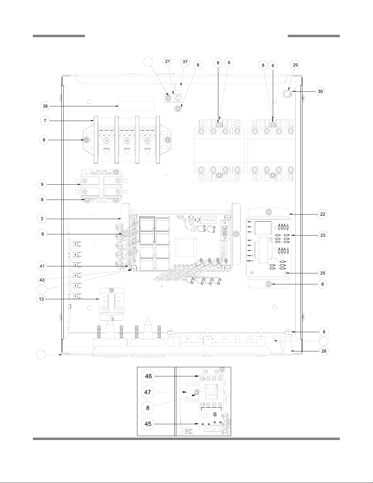
TOP MOUNT CONTROL BOX ASSEMBLY
19
10
8
1
44
For a 460V Unit, Replace item
9 with items 45, 46 & 47.
Details for 460 Volt Control Box
Page 2
Tempstar HH Series Technical Manual 7610-002-23-32
Issued: 09/14/2007 Revised: N/A
SECTION 5: PARTS SECTION
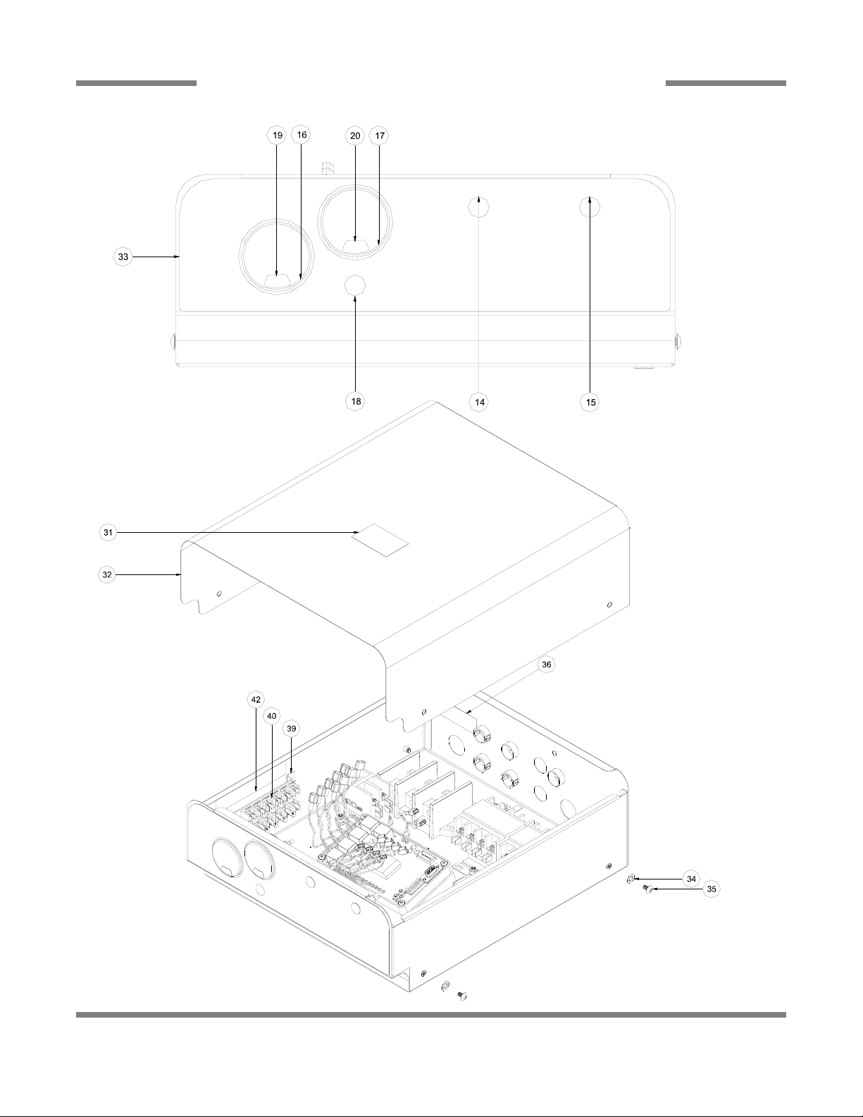
TOP MOUNT CONTROL BOX ASSEMBLY (CONTINUED)
20
Page 3

Tempstar HH Series Technical Manual 7610-002-23-32
Issued: 09/14/2007 Revised: N/A
SECTION 5: PARTS SECTION
TOP MOUNT CONTROL BOX ASSEMBLY (CONTINUED)
21
ITEM QTY DESCRIPTION Mfg. No.
1 1 Control Box Weldment 05700-003-30-14
2 1 Timer Bracket 05700-003-02-08
5 2 Locknut, 6-32 S/S Hex with Nylon Insert 05310-373-03-00
6 2 Contactor, 4 Pole 220V 1 Phase (Only 1 for No Booster and Steam Models) 05945-109-01-69
7 1 Terminal Block, 3 Pole 05940-011-48-27
8 19 Locknut, 10-24 S/S Hex with Nylon Insert 05310-373-01-00
*9 1 Contactor, 2 Pole 220V 20AMP (208-230 Volt Unit Only) 05945-002-74-20
10 1 Switch, 8 Button Tap Touch 05930-001-99-51
13 1 Relay, 240V, 50/60HZ, Top Mount 05945-111-47-51
14 1 Light, Green 05945-111-44-43
15 1 Light, Red 05945-11144-45
16 1 Thermometer, 96 Lead Rinse 06685-111-68-49
17 1 Thermometer, 48 Lead Wash 06685-111-68-48
18 1 Light, Amber 05945-111-44-44
19 1 Decal, Wash 150 Deg. 09905-002-97-61
20 1 Decal, Rinse 180 Deg. 09905-002-97-62
21 1 Wire Lug 05940-200-76-00
22 1 Bracket, Liquid Level Control Mounting 05700-002-13-22
23 1 Liquid Level Control 06680-200-08-21
25 3 Screw, 6-32 x 5/8" 05305-011-39-85
26 2 Spacer, Switch Panel 05700-002-50-02
30 1 Clamp, Nylon Hose .25 - .312 05975-002-61-43
31 1 Decal, Warning-Disconnect Power 09905-100-75-93
32 1 Cover, Control Box 05700-002-23-03
33 1 Decal, Control Box 09905-003-21-90
34 4 Lockwasher, #10 Internal Tooth 05311-273-03-00
35 4 Screw, 10-32 x 3/8" Phillips Truss Head 05305-173-12-00
36 1 Decal, Copper Conductors 09905-011-47-35
37 1 Decal, Ground 09905-011-86-86
38 1 Decal, L1, L2 09905-002-78-67
39 1 Bracket, Fuse Strip Holder 05700-002-42-03
40 1 Holder, Fuse, 6 Pole 05920-002-42-13
41 1 Timer, Universal 05945-003-33-09
42 1 Decal, Dispenser Connection 09905-003-34-09
43 4 Screw, 10-32 X 1 Phillips Pan Head 05305-002-19-42
44 4 Locknut, 10-32 S/S Hex with Nylon Insert 05310-373-02-00
*45 1 Overload, TK-ONY, (460 Volt Unit Only) 05945-002-65-02
*46 1 Motor Contactor, SC-03Y, (460 Volt Unit Only) 05945-002-65-00
*47 1 Din Rail 2-3/4” (460 Volt Unit Only) 05700-001-84-65
* For a 460V Unit, Replace item 9 with items 45, 46 & 47.
Page 4
Tempstar HH Series Technical Manual 7610-002-23-32
Issued: 09/14/2007 Revised: N/A
SECTION 5: PARTS SECTION
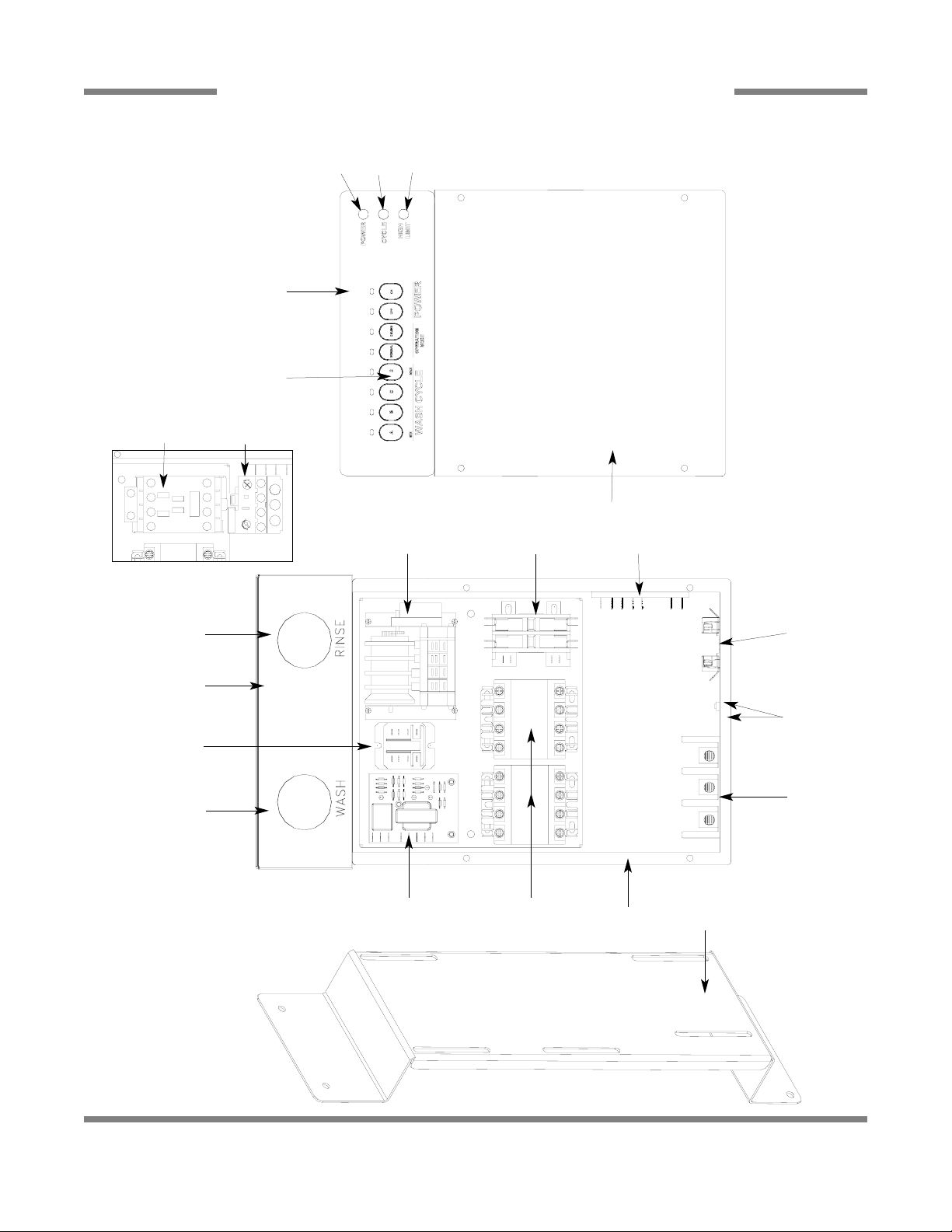
SIDE MOUNT CONTROL BOX ASSEMBLY
22
4
7, 8
9
13
29
30
31
32
*27, *28
25, 26
14, 11
34
35
15, 16
17
10, 11
12
1, 2, 3
5, 6
24, 11
22, 23, 21
18, 19
20, 21
* Represents an item not shown.
Details for 460V Control Box
For a 460V Unit, Replace item 15
with items 34 & 35.
Page 5

Tempstar HH Series Technical Manual 7610-002-23-32
Issued: 09/14/2007 Revised: N/A
SECTION 5: PARTS SECTION
SIDE MOUNT CONTROL BOX ASSEMBLY (CONTINUED)
23
ITEM QTY DESCRIPTION Mfg. No.
1 1 Bracket, Electrical Box Mounting 05700-002-18-48
2 9 Locknut, 1/4"-20 S/S Hex with Nylon Insert 05310-374-01-00
3 9 Washer, 1/4"-20 I.D. S/S 05311-174-01-00
4 1 Control Box Weldment, Right Hand 05700-002-06-48
4 1 Control Box Weldment, Left Hand 05700-002-23-08
5 2 Contactor, 4 Pole 220V 1 Phase (Only 1 for No Booster and Steam Models) 05945-109-01-69
6 4 Screw, 10-32 x 1/2" Phillips Pan Head with Washer 05305-002-32-37
7 1 Liquid Level Control 06680-200-08-21
8 3 Screw, 6-32 x 5/8" 05305-011-39-85
9 1 Thermometer, 48 Lead, Wash 06685-111-68-48
1 Decal, Wash 150 Deg. 09905-002-97-61
10 1 Relay, 240V, 50/60HZ, Top Mount 05945-002-47-74
11 8 Screw, 6-32 x 3/8" SEMS with External Tooth Washer 05305-002-25-91
12 1 Decal, Control Box Gauge 09905-002-10-69
13 1 Thermometer, 96 Lead Rinse 06685-111-68-49
1 Decal, Rinse 180 Deg. 09905-002-97-62
14 1 Timer, 4CKT 208-230V Single REV (Shown) 05945-303-31-00
14 1 Timer, Universal 05945-003-07-48
1 Timer Bracket 05700-003-02-08
6 Holder, Keystone 05940-002-21-87
1 Keying Plug 05940-003-11-66
2 Connector 05940-003-11-65
15 1 Contactor, 2 Pole 220V 20AMP( 208-230 Volt Unit Only) 05945-002-74-20
16 3 Screw, 10-32 x 3/8" Phillips Pan Head 05305-173-26-00
17 1 Timer, Cycle Delay 05945-002-13-78
18 1 Terminal Block, 3 Pole 05940-011-48-27
19 1 Decal, L1, L2, L3 09905-101-12-66
20 1 Decal, Copper Conductors 09905-011-47-35
21 4 Locknut, 10-24 S/S Hex with Nylon Insert 05310-373-01-00
22 1 Wire Lug 05940-200-76-00
23 1 Decal, Ground 09905-011-86-86
24 1 Holder, Fuse 05920-401-03-14
25 1 Cover, Control Box Weldment 05700-002-06-52
26 4 Bolt, 10-32 x 1/2" Slotted Truss 05305-173-04-00
27* 1 Switch, 8 Button Tap Touch 05930-001-99-51
28* 1 Spacer, Switch Panel 05700-002-50-02
29 1 Decal, Control Box Cover 09905-002-00-45
30 1 Light, Red 05945-504-07-18
31 1 Light, Green Indicator 05945-504-08-18
32 1 Light, Amber 05945-504-06-18
33* 1 Cover, Dielectric Control Panel 05700-021-50-89
34 1 Contactor, 2 Pole 220V 20AMP (460 Volt Unit Only) 05945-002-65-00
35 1 Overload (460 Volt Unit Only) 05945-002-65-01
* Represents an item not shown.
Page 6
Tempstar HH Series Technical Manual 7610-002-23-32
Issued: 09/14/2007 Revised: N/A
SECTION 5: PARTS SECTION
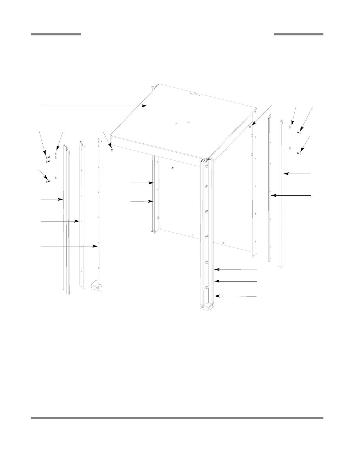
HOOD ASSEMBLY
24
ITEM QTY DESCRIPTION Mfg. No.
1 1 Hood Weldment (Side Mount Control Box) (Shown) 05700-002-01-23
1 1 Hood Weldment (Top Mount Control Box) 05700-003-52-53
2 6 Bolt, 1/4"- 20 x 5/8" Long Hex 05305-274-24-00
3 26 Washer, 1/4" ID S/S 05311-174-01-00
4 26 Locknut, 1/4"-20 S/S Hex with Nylon Inserts 05310-374-01-00
5 26 Bolt, 1/4"-20 x 1/2" Long Hex 05305-274-02-00
6 2 Right/Left Front Outer Door Guide 05700-031-76-85
7 2 Right/Left Front Inner Door Guide 05700-031-76-82
8 2 Right/Left Front Hood Support Weldment 05700-002-17-68
9 1 Left Rear Outer Door Guide 05700-031-76-34
10 1 Left Rear Inner Door Guide 05700-031-76-33
11 1 Right Rear Outer Door Guide 05700-031-76-35
12 1 Right Rear Inner Door Guide 05700-031-76-32
1
2
5
2
5
7
4
4
8
*9
*10
6
12
6
*7
*8
11
3
3
* Represents an item not shown.
Page 7
Tempstar HH Series Technical Manual 7610-002-23-32
Issued: 09/14/2007 Revised: N/A
SECTION 5: PARTS SECTION
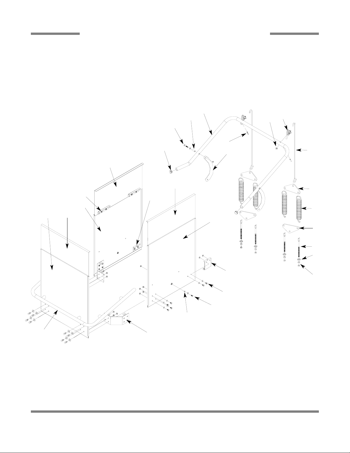
CANTILEVER ARM/DOOR ASSEMBLIES
17, 18
35, 24
33, 34
6
3, 4, 5
2
1
7
28
27, 22
29, 30 31, 32
26
25, 4, 5
23, 4, 24
10
9
19, 20
17, 18
36, 22
21, 22
8
11
13
12
14
15
16
12
25
Page 8

Tempstar HH Series Technical Manual 7610-002-23-32
Issued: 09/14/2007 Revised: N/A
SECTION 5: PARTS SECTION
CANTILEVER ARM/DOOR ASSEMBLIES (CONTINUED)
26
ITEM QTY DESCRIPTION Mfg. No.
1 1 Cantilever Arm 05700-031-92-44
2 2 Sleeve, Cantilever Arm 05700-000-85-69
3 2 Screw, 1/4"-20 x 1 1/2" Long Hex Head 05305-274-23-00
4 4 Washer, 1/4" ID S/S 05311-174-01-00
5 4 Locknut, 1/4"-20 S/S Low Profile with Nylon Insert 05310-374-02-00
6 4 Plug, Cantilever 05340-011-35-00
7 2 Connecting Link 05700-021-92-45
8 2 Spring Pin, 1/4" x 1 1/8" Long 05315-407-06-00
9 2 Y oke Assembly 05700-000-75-77
10 2 Nut, 3/8"-16 S/S Hex Locking 05310-256-04-00
11 2 Rod, Spring Connecting 05700-002-00-91
12 4 Plate, Spring Multiplier 05700-002-00-88
13 4 Spring, Cantilever Door 05340-111-35-22
14 4 Bolt, Cantilever Hanger Eye 3/8"-16 05306-956-05-00
15 4 Washer, Impeller 05311-176-02-00
16 8 Nut, 3/8"-16 S/S Hex 05310-276-01-00
* 2 Door, Upper, Left and Right Assemblies 05700-002-01-30
17 2 Door, Upper, Left and Right Weldment 05700-002-29-59
18 4 Glide, Upper Door 05700-002-00-83
* 1 Door, Lower, Right Assembly 05700-002-01-33
19 1 Door, Lower, Right 05700-031-76-80
20 2 Glide, Lower Door 05700-002-23-64
21 1 Door Stop Magnet Assembly 06401-003-08-68
* 1 Door Stop Magnet Weldment 05700-002-01-27
* 1 Magnet 05930-111-69-25
* 2 End Cap 05700-011-60-92
22 6 Wear Button 05700-011-88-01
23 20 Screw, 1/4"-20 x 5/8" 05305-274-24-00
24 20 Locknut, 1/4"-20 S/S Hex with Nylon Insert 05310-374-01-00
25 2 Screw, 1/4"-20 x 1/2" Long Hex Head 05305-274-02-00
26 2 Spacer, PB Bolt 05700-000-29-40
27 2 Bracket, Door Connector 06401-003-08-75
28 1 Handle, Front Door Weldment 06401-003-08-67
* 1 Door, Lower, Front Assembly 05700-002-01-31
29 1 Door, Lower, Front 05700-031-76-77
30 2 Glide, Lower Door 05700-002-23-64
* 1 Door, Upper Front Assembly 05700-002-24-92
31 1 Door, Upper, Front Weldment 05700-002-29-57
32 2 Glide, Upper Door 05700-002-00-83
* 1 Door, Lower, Left Assembly 05700-002-01-32
33 1 Door, Lower, Left 05700-031-76-79
34 2 Glide, Lower Door 05700-002-23-64
35 6 Door Stop Weldment 05700-002-29-60
36 1 Door Stop 06401-003-08-69
37* 2 Cantilever Arm Support Bracket 09515-003-15-64
38* 6 Wear Button 05700-011-88-01
Page 9
Tempstar HH Series Technical Manual 7610-002-23-32
Issued: 09/14/2007 Revised: N/A
SECTION 5: PARTS SECTION
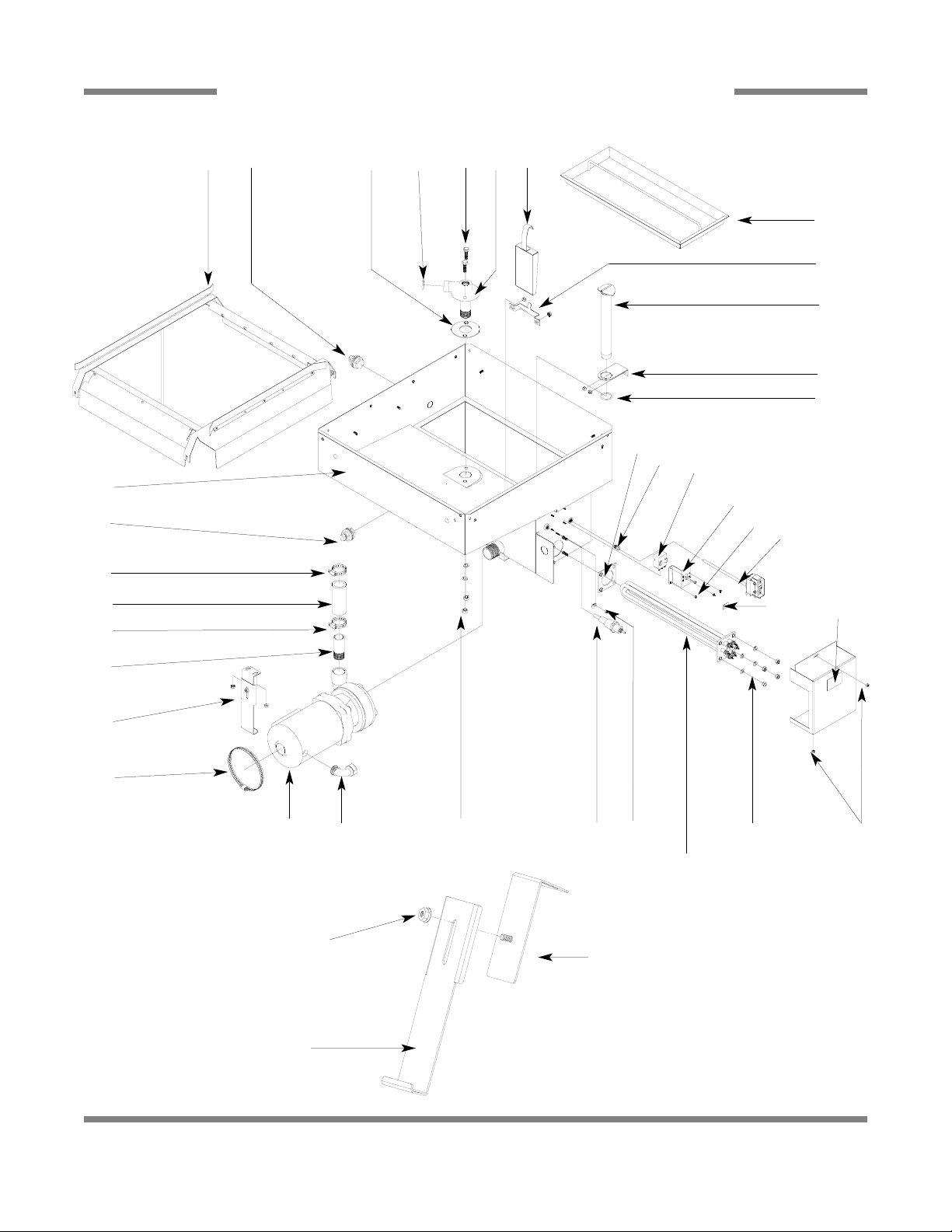
TUB ASSEMBLY
27
11
9, 10
2 3 6 7
12
13, 10
14
4 8
3
15
5
SEE PAGE ENTITLED
“WASH MOTORS”
29, 30
21, 2220 23 24, 25
26, 27
35
32
34
33
25
34
31
1
28
16
15
17
18, 10
19
Nut, 1/4”-20 Serrated Nut
05310-011-66-49
Bracket, Motor Support Weldment
05700-002-20-42
Pump Support Adjustable Bracket
05700-002-20-41
* Represents an item not shown.
SEE PAGE ENTITLED
“WASH/RINSE-HEATERS”.
Page 10

Tempstar HH Series Technical Manual 7610-002-23-32
Issued: 09/14/2007 Revised: N/A
SECTION 5: PARTS SECTION
TUB ASSEMBLY (CONTINUED)
28
ITEM QTY DESCRIPTION Mfg. No.
1 1 Tub Weldment 05700-002-01-25
2 1 Rack Assembly 05700-002-01-00
3 2 Bulk Head Plug 04730-609-05-00
4 1 Gasket 05700-111-35-03
5 1 O-ring 05330-400-05-00
6 4 Bolt, Hex 3/8”-16 x 1 1/4" Long 05305-276-10-00
7 1 Lower Wash Manifold Weldment 05700-031-46-00
8 1 Suction Strainer Weldment 05700-002-16-13
9 1 Suction Strainer Bracket 05700-002-18-28
10 8 Locknut, 1/4"-20 with Nylon Insert 05310-374-02-00
11 1 Strainer Weldment 05700-031-50-07
12 1 Wash Overflow Weldment 05700-001-25-69
* 1 Support, Ball Stop Lift 05700-002-91-55
* 1 Ball Stop Lift 05700-003-07-50
13 1 Overflow Support Bracket 05700-001-27-55
14 1 O-Ring 05330-400-05-00
15 2 Clamp, Hose 1 5/16” to 2 1/4” 04730-719-01-37
16 1 Discharge Hose 05700-011-88-24
17 1 Nipple 05700-021-34-84
18 1 Pump Support Bracket Assembly 05700-002-22-73
19 1 Clamp, Hose 5 5/8" to 6" 04730-011-34-90
20 1 Connector, 1/2” 90° 05975-111-01-00
21 4 Nut, 3/8"-16 S/S Hex 05310-276-01-00
22 4 Lockwasher, 3/8” 05311-276-01-00
23 1 High Water Probe 06680-200-02-68
24 1 Clamp, 1/8" Nylon 05975-601-10-15
25 3 Locknut, 6-32 with Nylon Insert 05310-373-03-00
26 4 Lockwasher, 5/16", S/S, Split 05311-275-01-00
27 4 Nut, Hex, 5/16"-18, S/S 05310-275-01-00
28 4 Locknut, 10-24 with Nylon Insert 05310-373-01-00
29 1 Cover, Wash Heater 05700-031-47-57
30 1 Decal, Warning-Disconnect Power 09905-100-75-93
31 1 Decal, High Limit 09905-011-84-32
32 1 Wash Heater Gasket 05330-011-47-79
33 1 Thermostat Bracket 05700-011-81-64
34 1 Thermostat, Regulating with Imperial Brass Fitting 06401-003-18-22
35 1 Thermostat, High Limit 05930-011-49-43
Magnetic Reed Switch
05930-003-05-84
Associated Hardware:
Lockwasher, #8 Internal Tooth 05311-272-03-00
Locknut, 1/4”-20 S/S Hex w/Nylon Insert 05310-374-01-00
Screw, 8-32 x 3/4” Round Head 05305-172-06-00
Page 11

Tempstar HH Series Technical Manual 7610-002-23-32
Issued: 09/14/2007 Revised: N/A
SECTION 5: PARTS SECTION
STEAM TUB ASSEMBLY
29
12
10, 11
2 3
4
7 8
13
14, 11, 15
5 9
3
16
6
22, 2321
24
25 27, 28
26
1
29
17
16
18
19
20
Pump Support Bracket Complete Assembly
05700-002-00-46
Nut, 1/4”-20 Serrated Nut
05310-011-66-49
Bracket , Motor Support Weldment
05700-002-68-31
Pump Support Adjustable Bracket
05700-002-20-41
* Represents an item not shown.
Page 12

Tempstar HH Series Technical Manual 7610-002-23-32
Issued: 09/14/2007 Revised: N/A
SECTION 5: PARTS SECTION
STEAM TUB ASSEMBLY (CONTINUED)
30
ITEM QTY DESCRIPTION Mfg. No.
1 1 Tub Weldment 05700-002-63-13
2 1 Rack Assembly 05700-002-01-00
3 2 Bulk Head Plug 04730-609-05-00
4 1 Motor & Pump Assembly See page entitled Wash Motors
5 1 Gasket 05700-111-35-03
6 1 O-ring 05330-400-05-00
7 4 Bolt, Hex 3/8”-16 x 1 1/4" Long 05305-276-10-00
8 1 Lower Wash Manifold Weldment 05700-031-46-00
9 1 Suction Strain Weldment 05700-001-22-23
10 1 Suction Strain Bracket 05700-001-22-24
11 8 Locknut, 1/4"-20 with Nylon Insert 05310-374-02-00
12 1 Strainer Weldment 05700-021-50-07
13 1 Wash Overflow Weldment 05700-001-25-69
* 1 Support, Ball Stop Lift 05700-002-91-55
* 1 Ball Stop Lift 05700-003-07-50
14 1 Overflow Support Bracket 05700-001-27-55
15 1 O-Ring 05330-400-05-00
16 2 Clamp, Hose 1 5/16” to 2 1/4” 04730-719-01-37
17 1 Discharge Hose 05700-011-88-24
18 1 Nipple 05700-021-34-84
19 1 Pump Support Bracket Assembly 05700-002-00-46
20 1 Clamp, Hose 5 5/8" to 6" 04730-011-34-90
21 1 Connector, 1/2” 90° 05975-111-01-00
22 4 Nut, 3/8"-16 S/S Hex 05310-276-01-00
23 4 Lockwasher, 3/8” 05311-276-01-00
24 1 Steam Coil Assembly 05700-002-08-62
25 1 Probe, High Water 06680-200-02-68
26 1 Thermostat, Regulating with Imperial Brass Fitting 06401-003-18-23
27 1 Cover, Wash Heater 05700-031-47-57
28 1 Decal, Warning-Disconnect Power 09905-100-75-93
29 2 Locknut, 10-24 with Nylon Insert 05310-373-01-00
Page 13

Tempstar HH Series Technical Manual 7610-002-23-32
Issued: 09/14/2007 Revised: N/A
SECTION 5: PARTS SECTION
FRAME ASSEMBLY
31
Bullet Foot
05340-108-02-06
Bullet Foot, 415V
05340-002-14-55
Flange Feet
05340-002-01-15
Cover, Front Panel
05700-002-01-42
Frame Weldment
05700-002-03-49
Frame Weldment, 415V
05700-002-62-41
Page 14

Tempstar HH Series Technical Manual 7610-002-23-32
Issued: 09/14/2007 Revised: N/A
SECTION 5: PARTS SECTION
RINSE TANK ASSEMBLY
32
ITEM QTY DESCRIPTION Mfg. No.
1 1 Booster Tank Weldment 05700-002-10-19
2 2 Locknut, 10-24 with Nylon Insert 05310-373-01-00
3 2 Washer, #10 S/S Flat 05311-173-01-00
4 1 Decal, Warning - Disconnect Power 09905-100-75-93
5 1 Booster Tank Cover Weldment 05700-002-16-51
6 6 Nut, Hex, 5/16"-18 05310-275-01-00
7 1 Thermostat, High Limit 05930-011-49-43
8 1 Thermostat, Regulating with Imperial Brass Fitting 06401-011-66-55
9 6 Lockwasher, 5/16” Split 05311-275-01-00
10 1 Gasket, Rinse Heater 05330-200-02-70
11 4 Locknut, 1/4”-20 with Nylon Insert 05310-374-01-00
12 4 Washer, 1/4” S/S Flat 05311-174-01-00
4
6, 9
7
1
10
8
5
2, 3
11
12
8 4
SEE PAGE ENTITLED
“WASH HEATERS/RINSE HEATERS”.
Page 15

Tempstar HH Series Technical Manual 7610-002-23-32
Issued: 09/14/2007 Revised: N/A
SECTION 5: PARTS SECTION
COIL ASSEMBLY
Stand C, Steam Coil Support
05700-002-08-52
Steam Coil Weldment
05700-021-41-38
Stand D, Steam Coil Support
05700-002-08-53
Stand B, Steam Coil Support
05700-002-08-51
Adapter, Steam Coil Nut
2 per assembly
05310-011-17-85
Washer, Steam Coil
2 per assembly
05700-001-17-87
Gasket, Steam Coil
4 per assembly
05700-001-17-86
Stand A, Steam Coil Support
05700-002-08-50
Complete Steam Coil Assembly
05700-002-08-62
33
Page 16

Tempstar HH Series Technical Manual 7610-002-23-32
Issued: 09/14/2007 Revised: N/A
SECTION 5: PARTS SECTION
INCOMING STEAM PLUMBING ASSEMBLIES
34
Union, 3/4’’ NPT, Black Iron
04730-912-01-01
Elbow, 3/4” 90° Street
04730-011-87-37
Elbow, 3/4” 90° Street
04730-011-87-37
Elbow, 3/4” 90° Street
04730-011-87-37
Steam Trap, 3/4” NPT F&T
06680-500-02-77
Nipple, Close, 3/4’’ NPT, Black Iron
04730-907-01-00
Nipple, Close, 3/4’’ NPT, Black Iron
4 per assembly
04730-907-01-00
Bushing, Reducing, 3/4’’ to 1/2’’
04730-911-02-34
Bushing, Reducing, 3/4’’ to 1/2’’
04730-911-02-34
Union, 3/4’’ NPT, Black Iron
2 per assembly
04730-912-01-01
3/4” NPT Black Iron Pipe
05700-002-20-83
Gate Valve, 3/4” NPT
04820-100-19-00
Bracket, Steam Plumbing Support
05700-002-20-83
Y-Strainer, 3/4” NPT Black Iron
04730-217-01-32
Solenoid Valve, Steam Plumbing, 220V
04820-002-01-32
To order this complete assembly, use part number:
05700-002-01-55
To order this complete assembly, use part number:
05700-002-01-60
Page 17

Tempstar HH Series Technical Manual 7610-002-23-32
Issued: 09/14/2007 Revised: N/A
SECTION 5: PARTS SECTION
MOTORS - WASH HEATERS - RINSE HEATERS
35
The models covered in this manual come supplied with various wash motor assemblies (a wash motor assembly includes the
wash motor and the pump end), depending on the characteristics of the machine. To ensure that you order the correct wash
motor assembly for the model you are servicing, please refer to the following table:
Model
Volts Hz Phase Wash Motor Assembly
Tempstar HH 415 50 3 06105-002-45-07
Tempstar HH, HH NB, HH S 208 60 1 06105-002-01-29
Tempstar HH, HH NB, HH S 230 60 1 06105-002-01-29
Tempstar HH, HH NB, HH S 208 60 3 06105-002-01-29
Tempstar HH, HH NB, HH S 230 60 3 06105-002-01-29
Tempstar HH, HH NB, HH S 460 60 3 06105-002-09-30
Important note: When servicing a wash motor, it is important to refer to the wiring schematic found on the motor, to ensure
that the motor is wired correctly. Different manufacturers of motors may not use the same wire color codes and therefore, your
new motor, which may have been built by someone different than who built your original motor, may not connect using the same
wires. Always refer to the wiring diagrams on the motor you are installing. If the motor you are installing has had the schematic removed, contact Jackson MSC immediately for technical support.
The Tempstar models covered in this manual come supplied with various heaters, depending on the characteristics of the machine.
To ensure that you order the correct heater for the model you are servicing, please refer to the following table:
40
°F Rise
70
°F Rise
Model
Volts Hz Phase Wash Heater Rinse Heater (12 KW) Rinse Heater (14 KW)
Tempstar HH 415 50 3 04540-002-43-09 04540-002-43-10 N/A
Tempstar HH 208 60 1 04540-121-47-39 04540-121-47-40 04540-121-63-38
Tempstar HH 230 60 1 04540-121-47-39 04540-121-47-40 04540-121-63-38
Tempstar HH 208 60 3 04540-121-47-39 04540-121-47-40 04540-121-63-38
Tempstar HH 230 60 3 04540-121-47-39 04540-121-47-40 04540-121-63-38
Tempstar HH 460 60 3 04540-121-65-99 04540-100-01-15 04540-121-63-39
Tempstar HH NB 208 60 1 04540-121-47-39
Tempstar HH NB 230 60 1 04540-121-47-39
Tempstar HH NB 208 60 3 04540-121-47-39
Tempstar HH NB 230 60 3 04540-121-47-39
Tempstar HH NB 460 60 3 04540-121-65-99
Tempstar HH S 208 60 1 04540-121-47-39
Tempstar HH S 230 60 1 04540-121-47-39
Tempstar HH S 208 60 3 04540-121-47-39
Tempstar HH S 230 60 3 04540-121-47-39
Tempstar HH S 460 60 3 04540-121-65-99
Page 18

Tempstar HH Series Technical Manual 7610-002-23-32
Issued: 09/14/2007 Revised: N/A
SECTION 5: PARTS SECTION
INCOMING & OUTLET PLUMBING ASSEMBLIES
36
INCOMING PLUMBING
OUTLET PLUMBING
15
4
9
10
16
1
7
3
2
6
5
4
4
8
9
10
11
13
12
10
17
13
9
18
13
14
12
10
Page 19

Tempstar HH Series Technical Manual 7610-002-23-32
Issued: 09/14/2007 Revised: N/A
SECTION 5: PARTS SECTION
INCOMING & OUTLET PLUMBING ASSEMBLIES (CONTINUED)
37
ITEM QTY DESCRIPTION Mfg. No.
1 1 Water Pressure Regulator, 3/4" NPT 06685-011-58-22
2 1 Valve, Ball, 1/4" NPT 04810-011-72-67
3 1 Gauge, Pressure, 0-100 PSI 06685-111-88-34
4 2 Nipple, Close, 3/4" NPT 04730-207-34-00
5 1 Tee, Brass, 3/4" NPT x 3/4" NPT x 1/4" NPT 04730-211-04-00
6 1 Valve, Solenoid, 3/4" NPT 04810-100-03-18
7 1 Nipple, Brass, 3/4" NPT x 2" Long 04730-207-46-00
8 1 Elbow, 3/4" NPT, Brass, Street 04730-206-04-34
9 3 Union, 3/4" NPT, Brass with O-ring 05700-002-63-79
10 4 Adapter, 3/4" Male 04730-401-11-01
11 1 Tube, Copper, 3/4" x 48" Long 05700-011-87-89
12 2 Elbow, 3/4", 90°, #707 Copper 04730-406-16-01
13 3 Adapter, 3/4", 604-2 04730-401-10-01
14 1 Tube, Copper, 3/4" x 3 3/4" Long 05700-011-58-28
15 1 Vacuum Breaker, 3/4" NPT 04820-002-53-77
16 1 Tube, Copper, 3/4" x 44 3/8" Long 05700-002-25-05
17 1 Elbow, 3/4" 90° Copper to FSPS Brass 04730-406-41-01
18 1 Elbow, 3/4" 90° Copper to Copper Street 04730-406-40-01
19* 2 Double Pipe Clamp 05700-002-23-89
20* 1 Bracket, Incoming Plumbing Support 05700-021-34-02
When servicing plumbing components, take care not to damage the threads of each individual item. Damaged threads can
cause leaks and loss of pressure, which could adversely effect the performance of the dishmachine. It is strongly recommended
that teflon thread tape, used in conservative amounts, be applied to threads when joining components together . It is not advised
to use thread sealing compounds, sometimes referred to as “pipe dope”. Compounds can be ejected from the threads during
the tightening process and become lodged in key components, thereby rendering them useless. Some of the components
include the solenoid valve and the pressure gauge isolation ball valve.
Rinse Injector Weldment
1 per machine
05700-021-47-65
Plug, 1/8” NPT, Brass
3 per Rinse Injector
04730-209-07-37
Rinse Injector Gasket
2 per machine
05330-111-42-81
Page 20

Tempstar HH Series Technical Manual 7610-002-23-32
Issued: 09/14/2007 Revised: N/A
SECTION 5: PARTS SECTION
INCOMING PLUMBING (TEMPSTAR HH NB)
38
ITEM QTY DESCRIPTION Mfg. No.
1 1 Vacuum Breaker, 3/4" NPT 04820-002-53-77
2 1 Elbow, Brass, Street, 3/4" NPT 04730-206-04-34
3 1 Nipple, Brass, 3/4" NPT x 3" Long 04730-011-38-29
4 1 Union, 3/4" NPT, Brass with O-ring 05700-002-63-79
5 3 Nipple, Close, Brass, 3/4" NPT 04730-207-34-00
6 1 Valve, Solenoid, 3/4" NPT 04810-100-03-18
7 1 Tee, Brass, 3/4" NPT x 3/4" NPT x 1/4" NPT 04730-211-04-00
8 1 Pressure Gauge, 0-100 PSI 06685-111-59-66
9 1 Valve, Ball, Bronze, 1/4" NPT 04810-011-72-67
10 1 Water Pressure Regulator 06685-011-58-22
2
3
4 5 6
7
5
5
81 9
10
Page 21

Tempstar HH Series Technical Manual 7610-002-23-32
Issued: 09/14/2007 Revised: N/A
SECTION 5: PARTS SECTION
39
DRAIN QUENCH ASSEMBLY
From the existing drain, attach the two additional Tees using the 1-1/2” NPT Close Nipples. Tighten the Reducers into the Tees
as shown above. Attach the Modified Compression Fitting into the 1-1/2” to 1/4” Reducer. Position the bulb of the thermostat
so that it rests approximately 1/4” from the bottom of the Tee. Tighten the Modified Compression Fitting as required. Attach to
the incoming cold water line. Use pipe dope or thread tape as required to prevent any leaks.
Thermostat
05930-003-13-65
Solenoid Valve
04810-100-09-18
To Cold Water Supply
Nipple, Close, 1/2” NPT
(Not Shown)
04730-207-15-00
Valve, Check, 1/2”
(Not Shown)
04820-002-55-77
Lid, Drain Quench
05700-002-67-16
Box, Drain Quench
05700-002-69-96
Reducer, 1-1/2” to 1/2”
04730-002-55-75
Tee, 1-1/2” x 1-1/2” x 1-1/2”
04730-011-69-93
Modified Compression
Fitting
05700-001-16-52
Reducer, 1-1/2” x 1/4”
04730-002-55-76
To Dishmachine Drain
Nipple, 1-1/2” NPT
04730-207-40-00
Elbow, 1-1/2” 90° Street
04730-206-32-00
Drain Quench
Assembly
06401-002-59-52
Page 22

Tempstar HH Series Technical Manual 7610-002-23-32
Issued: 09/14/2007 Revised: N/A
SECTION 5: PARTS SECTION
3/4” SOLENOID VALVE & 3/4” VACUUM BREAKER REPAIR PARTS KITS
40
Screw
Data Plate
Coil & Housing
Valve Bonnet
Spring
06401-003-07-40
Plunger
06401-003-07-40
O-Ring
06401-003-07-42
Diaphragm
Retainer
Diaphragm
06401-003-07-42
Screen
Retainer
Mesh Screen
Valve Body
Complete 240 Volt Solenoid Valve Assembly
04810-100-03-18
Coil & Housing only
06401-003-07-44
Complete Vacuum Breaker Assembly
04820-002-53-77
Components of Repair Kit
06401-003-06-24
Cap Screw
Data Plate
Cap
O-Ring
Plunger
Body
Cap Retainer
Page 23

Tempstar HH Series Technical Manual 7610-002-23-32
Issued: 09/14/2007 Revised: N/A
SECTION 5: PARTS SECTION
WASH & RINSE ARM/MANIFOLD ASSEMBLIES
41
13
16
19
14
11
12
15
15
2, 3, 4
5
7
17, 8
6, 18
5
9
7
1
DETAIL “B”
WASH ARMS & MANIFOLD
DETAIL “A”
FINAL RINSE ARMS & MANIFOLD
18
18
18
18
5
10
21
17
2, 3, 19
5
21
9, 18
1
Page 24

Tempstar HH Series Technical Manual 7610-002-23-32
Issued: 09/14/2007 Revised: N/A
SECTION 5: PARTS SECTION
WASH & RINSE ARM/MANIFOLD ASSEMBLIES (CONTINUED)
42
ITEM QTY DESCRIPTION Mfg. No.
1 1 Upper Manifold 05700-031-34-82
2 4 Nut, 3/8"-16 S/S Hex 05310-276-01-00
3 4 Lockwasher, 3/8 05311-276-01-00
4 2 Bolt, Hex 3/8”-16 x 7/8" Long 05306-011-36-95
5 2 O Ring 05330-111-35-15
6 1 Positioning Bracket, Manifold Tube 05700-011-34-63
7 1 Tube, Wash Manifold 05700-031-92-58
8 2 Gasket, Manifold 05700-111-35-03
* 1 Wash Arm Assembly 05700-021-35-39
9 1 Wash Arm Weldment 05700-021-35-93
10 1 Bearing Assembly 05700-021-35-97
* 1 O-ring 05330-002-60-69
* 1 Wash Arm Assembly, 415V 05700-021-63-81
9 1 Wash Arm Weldment, 415V 05700-021-63-42
10 1 Bearing Assembly , 415V 05700-021-63-80
* 2 Rinse Arm Assembly 05700-002-58-09
11 2 Clip, Retaining, Rinse Head Bushing 05340-112-01-11
12 4 Washer 05330-011-42-10
13 2 Bushing, Rinse Head 05700-021-33-84
14 2 Rinse Arm 05700-031-49-58
15 4 Plug 04730-609-04-00
16 2 Bearing 03120-002-72-24
17 1 Lower Wash Manifold Weldment 05700-002-21-70
18 5 Locknut, 1/4"-20 S/S Hex with Nylon Insert 05310-374-01-00
19 1 Rinse Manifold Weldment 05700-002-01-19
20 2 Bolt, Hex 3/8”-16 x 1 1/4" Long 05305-276-10-00
21 1 Wash Arm, Double Assembly 05700-031-92-49
21 1 Wash Arm, Double Assembly, 415V 05700-002-46-86
Page 25

Tempstar HH Series Technical Manual 7610-002-23-32
Issued: 09/14/2007 Revised: N/A
SECTION 5: PARTS SECTION
460 VOLT MACHINE TRANSFORMER MOUNTING BOX
460V Transformer
05950-111-65-93
2 Amp Circuit Breaker
05925-111-64-18
Transformer Mounting Bracket
05700-031-62-82
Transformer Mounting Box
05700-002-10-01
Transformer Mounting Box Top (not shown)
05700-000-78-53
43
Page 26

Tempstar HH Series Technical Manual 7610-002-23-32
Issued: 09/14/2007 Revised: N/A
SECTION 5: PARTS SECTION
SAFETY DOOR INTERLOCK/DOOR OVERRIDE INSTRUCTIONS
44
Safety Door Interlock Box Bottom
05700-001-21-26
Safety Door Interlock Box Cover
05700-001-21-27
Other Safety Door Interlock (SDI)
components (not shown):
Pipe Clamp (found on the side of the machine)
05700-000-35-05
Solenoid, Electrical Interlock Option
04810-100-61-33
Relay
05945-111-47-51
Latch access hole
The following instructions are for Tempstar HH models equipped with the Safety Door Interlock option. These instructions are to
only be used in the event that the door interlock fails to unlatch and the doors are unable to be opened.
1. To manually disengage, find the latch access hole.
2. Using a screwdriver, punch or even a metal utensil, gently insert the tip into the access hole, making contact with the latching
arm.
3. With a minimal amount of force, push the latching arm back, disengaging the interlock.
4. The doors should open now.
Page 27

Tempstar HH Series Technical Manual 7610-002-23-32
Issued: 09/14/2007 Revised: N/A
SECTION 5: PARTS SECTION
EXHAUST FAN CONTROL OPTION
45
Delay Timer
05945-011-65-44
2” Din Rail
05700-002-36-09
Terminal Board
05940-011-84-41
Page 28

Tempstar HH Series Technical Manual 7610-002-23-32
Issued: 09/14/2007 Revised: N/A
SECTION 5: PARTS SECTION
FALSE PANEL INSTALLATION
46
1. Remove the rack assembly from the dishmachine.
2. The false panel will mount inside of the dishmachine.
3. Position the panel in the dishmachine on the side to be
closed.
4. Hold the panel against the side of the dishmachine and
push upward.
5. The panel will clip in at the top, inside of the unit.
6. The holes in the false panel will line up with the rack
assembly holes.
7. Re-install the screws for the rack assembly which will
secure the false panel to the unit.
8. Re-assemble the rack track in an “L” shape for a corner
operation.
Bottom of False Panel
Insert this
side first.
False Panel Positioned in unit.
Rack rail removed and repositioned for a corner operation.
False Panel
05700-002-52-54
Kit, False Panel with
Mounting Hardware
05700-002-52-89
 Loading...