

Jackson / Dalton Dishwasher M24STD-18 Installation Manual

Dishmachine Stand
Installation Instructions
FOR JACKSON MODEL:
M24STD-18
August 15, 2006
P/N 07610-003-26-83 Rev. A
Jackson MSC, INC.
P.O. BOX 1060
HWY. 25E
BARBOURVILLE, KY. 40906
FAX (606) 523-9196
PHONE (606) 523-9795
www.jacksonmsc.com
M24STD-18 INSTALLATION INSTRUCTIONS
Tools Required:
• Standard Allen wrench set
• Tube of food-grade silicon
• Silicon gun
• Rag
Time Requirements:
It is expected that it will take 40 minutes to
install the M24STD-18 dishmachine stand.
Notes:
• Ensure that the dishmachine stand is
level prior to placing the dishmachine
on the stand.
• Never attempt to lift a dishwasher on
your own. Always use other personnel
to help or the appropriate lifting devices
to prevent accident and injury.
Steps:
• Inspect the assembly to ensure that
there has been no freight damage. If
there is any damage, contact the
freight carrier immediately.
• Your package should contain the fol-
lowing:
• Stand platform weldment
• (4) legs
• (4) corner brackets
• (4) cross braces
• Instructions
• If any of these items are missing, im-
mediately contact Jackson Technical
Service at 1-888-800-5672.
• Remove the items from the box.
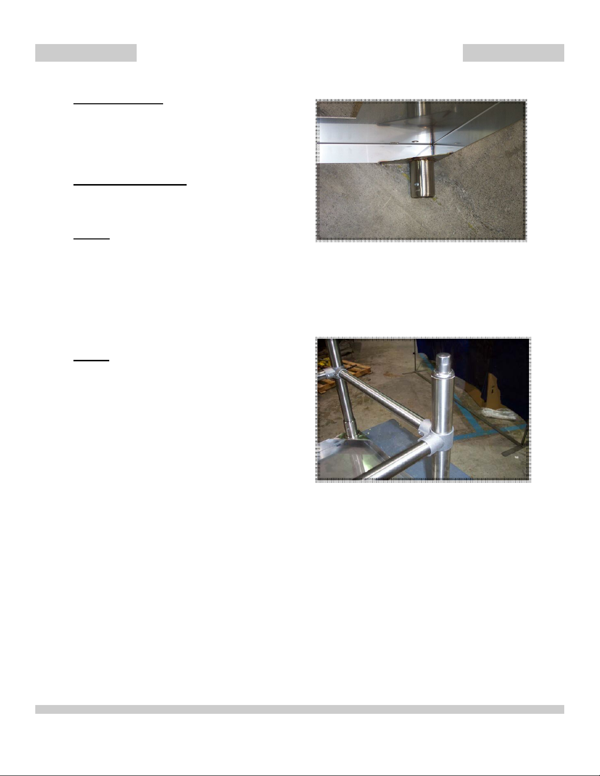
• Ensure that the set screws are located
within the leg sockets. If they are missing, immediately contact Jackson
Technical Service (See Figure 1).
• Verify that the foot of each leg can be
turned; this is how the stand will be adjusted in order to level it. Please note
that when assembled, there should be
a minimum of 6” (152.4mm) of space
Figure 1—Leg socket showing set screw
between the cross braces and the finished floor.
• Place the legs fully into the leg sockets
of the platform.
Figure 2—Cross brace set-up
• Slide a corner bracket down each leg.
Ensure that the set screws are pointed
inward.
• Ensuring that there is a minimum of
6” (152.4mm) and maximum of
7” (203.2mm) of clearance from the
bottom of the legs, tighten down the
corner braces.
• Insert the cross braces so that the as-
sembly resembles Figure 2.
• Tighten down on all of the set screws
for holding the cross braces in place.
• Tighten down the set screw for the leg
Installation Instructions 07610-003-26-83
Issued: 08-15-2006 Revised: N/A
2
 Loading...