

Page 1
JFT Series Technical Manual 7610-002-77-38
Issued: 03-16-2006 Revised: N/A
33
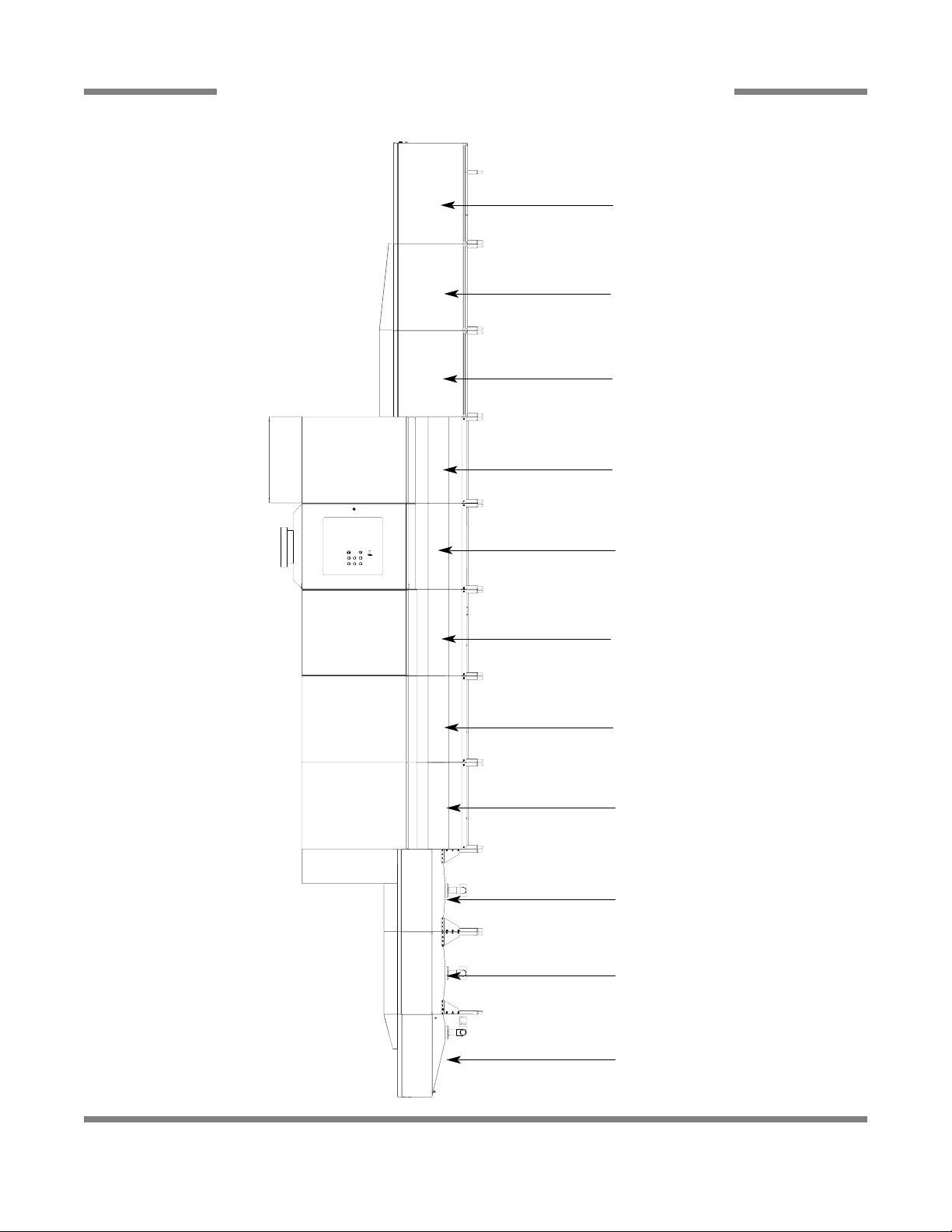
SECTION 6: PARTS SECTION
PARTS SECTION REFERENCE DIAGRAM
LOAD END SECTION
BEGINS ON PAGE 29
PREWASH SECTION
BEGINS ON PAGE 36
POWER RINSE SECTION
BEGINS ON PAGE 44
UNLOAD ANGLED EXPANSION
SECTION OPTION
BEGINS ON PAGE 64
UNLOAD STRAIGHT EXPANSION
SECTION OPTION
BEGINS ON PAGE 64
LOAD END ANGLED
EXPANSION SECTION OPTION
BEGINS ON PAGE 32
LOAD END STRAIGHT
EXPANSION SECTION OPTION
BEGINS ON PAGE 32
UNLOAD SECTION
BEGINS ON PAGE 67
WASH SECTION
BEGINS ON PAGE 40
BLOWER DRYER OPTION
BEGINS ON PAGE 61
FINAL RINSE
ELECTRICAL SECTION
BEGINS ON PAGE 48
PDF compression, OCR, web optimization using a watermarked evaluation copy of CVISION PDFCompressor
Page 2

34
LOAD END SECTION
PDF compression, OCR, web optimization using a watermarked evaluation copy of CVISION PDFCompressor
Page 3
JFT Series Technical Manual 7610-002-77-38
Issued: 03-16-2006 Revised: N/A
SECTION 6: PARTS SECTION
35
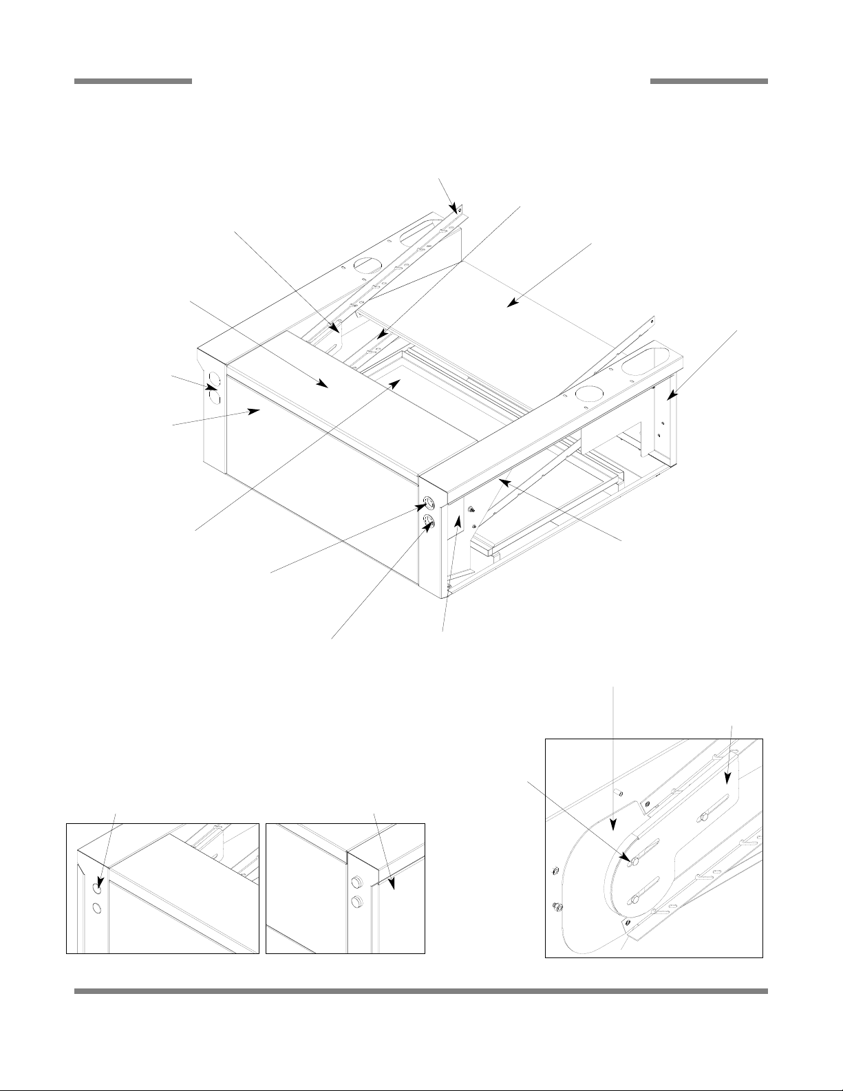
LOAD END ASSEMBLY
Strainer
05700-002-94-24
Back, Conveyor Belt Return
05700-002-72-57
Refer to Detail “A”
Refer to Detail “A”
Plug, Domed
05975-003-10-45
End Plate
05700-002-84-40
End Cap
05700-003-09-08
Switch, Red Stop
05930-002-80-73
Bushing, Snap 1 1/2”
05975-003-10-46
Bushing, Snap 1 1/2”
05975-003-10-46
Cover, Switch
05700-003-09-10
Bracket, Switch Holding
05700-003-09-11
Cover, Switch (Not Shown)
05700-002-97-85
Switch, Green Start
05930-002-80-60
Gasket Spacers
Qty.: 16
05330-003-04-12
Cover, Side
2 Per (Not Shown)
05700-003-09-09
Rail, Upper
2 per
05700-002-66-29
Rail, Rack Lower
2 per
05700-002-65-87
Run Off, Inlet/Outlet
05700-002-81-99
Front, Conveyor Belt Return
(Not Shown)
05700-002-72-58
Old Style Heyco Plug
Old Style With Extended Switches
Detail “A”
Plug, Heyco
05975-011-47-81
*Standoff, Belt Return
3 per side (Not Shown)
05700-002-82-27
Plate, Rail
05700-002-65-82
PDF compression, OCR, web optimization using a watermarked evaluation copy of CVISION PDFCompressor
Page 4
JFT Series Technical Manual 7610-002-77-38
Issued: 03-16-2006 Revised: N/A
SECTION 6: PARTS SECTION
36
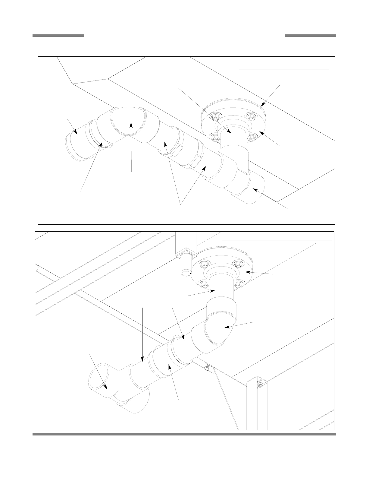
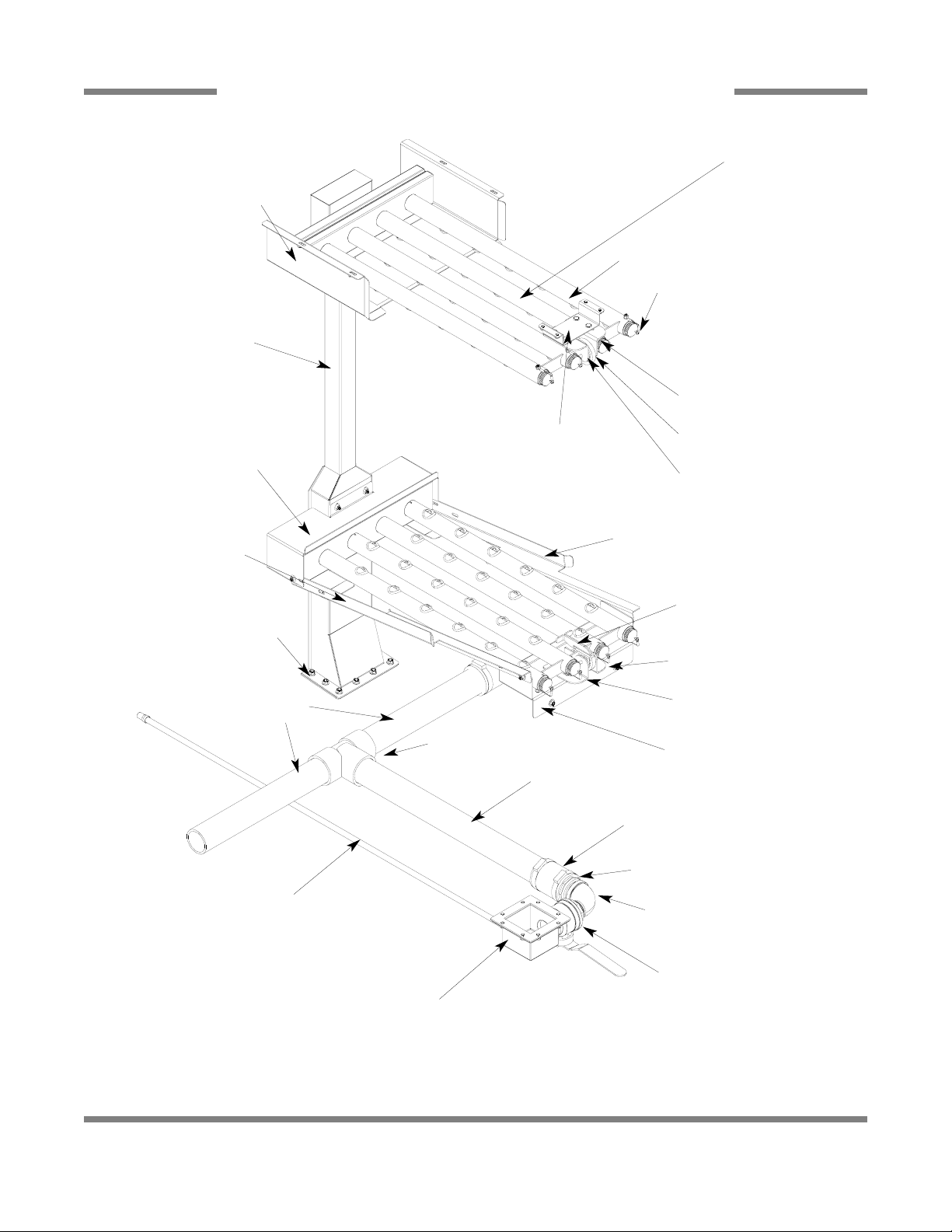
LOAD END & EXPANSION SECTION DRAIN PLUMBING ASSEMBLIES
2” No Hub
2 per
04730-002-66-87
CPVC, 2” ID x 3 3/4” Long
05700-002-69-58
Elbow, 2”, 90°, CPVC
04730-002-72-25
Tube, CPVC 2” x 6” Long
05700-003-05-00
Tube, CPVC 2” x 6” Long
05700-003-05-00
CPVC, 2” Tee
04730-002-66-09
Flange, 2 Inch
04730-003-04-25
Gasket, Drain
05330-003-04-26
LOAD SECTION DRAIN PLUMBING
EXP
ANSION SECTIONS DRAIN PLUMBING
Flange, 2 Inch
04730-003-04-25
Gasket, Drain
05330-003-04-26
Elbow, 2”, 90°, CPVC
04730-002-72-25
Tube, CPVC 2” x 6” Long
05700-003-05-00
CPVC, 2” Tee
04730-002-66-09
2” No Hub
2 per
04730-002-66-87
PDF compression, OCR, web optimization using a watermarked evaluation copy of CVISION PDFCompressor
Page 5
JFT Series Technical Manual 7610-002-77-38
Issued: 03-16-2006 Revised: N/A
SECTION 6: PARTS SECTION
37
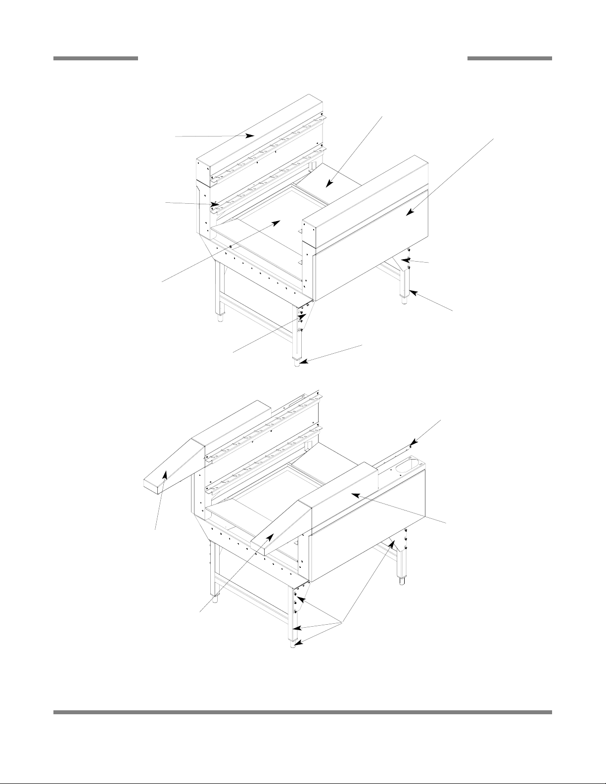
LOAD SECTION EXPANSION ASSEMBLIES
STRAIGHT EXPANSION ASSEMBLY
ANGLED EXPANSION ASSEMBLY
Rail Guard, Upper
2 per
05700-002-85-58
Rail, Lower
4 per
05700-002-65-07
Loader Section Strainer
05700-002-94-24
Panel, Side Dress
05700-003-09-09
Run Off Sheet
05700-003-09-17
Bullet Feet
4 per
05340-108-02-06
Right Support, Expansion Leg
2 per
05700-003-09-26
Left Support, Expansion Leg
2 per
05700-003-09-27
Leg Weldment
2 per
05700-003-09-28
Same as above
Same as above
Top, Load Expansion
Section
05700-003-09-21
Angled Top Right,
Load Expansion
05700-003-09-19
Angled Top Left,
Load Expansion
05700-003-09-20
PDF compression, OCR, web optimization using a watermarked evaluation copy of CVISION PDFCompressor
Page 6

JFT Series Technical Manual 7610-002-77-38
Issued: 03-16-2006 Revised: N/A
SECTION 6: PARTS SECTION
38
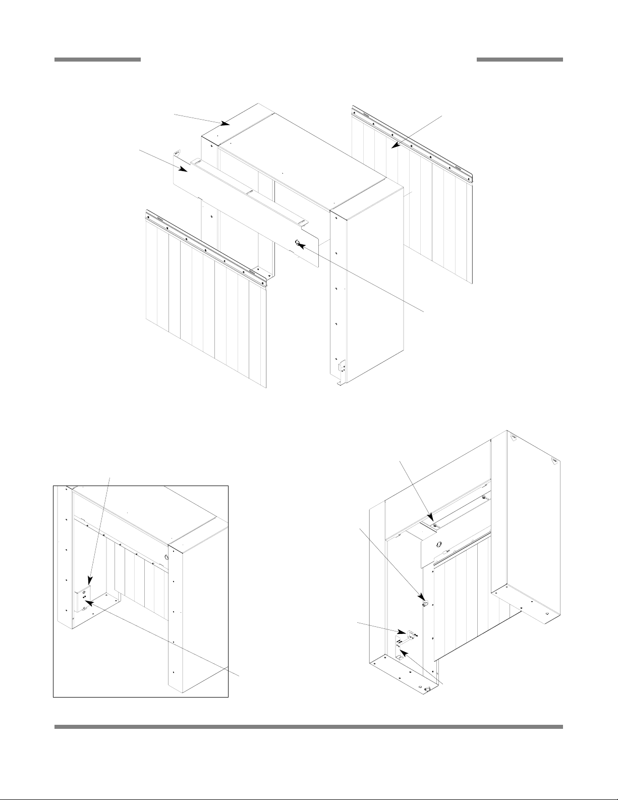
INSTALLATION OF LOAD SECTION EXPANSION ASSEMBLIES
When assembling the angled and/or straight expansion sections to the load end, you will have to move some parts from one
section to another. Shown below is how the sections look when all three are combined.
Whether you add one or both expansion sections, the runoff inlet/outlet has
to be removed from the load section
and installed on the end of the expansion section next to the prewash.
Load section shown with runoff inlet/outlet.
Staight expansion shown with both runoff plates.
Angled expansion shown with both runoff plates
and the angled top.
Runoff Inlet/Outlet
Runoff Plate
Angle Top
Please notice that the runoff plate
located in the last section was
installed into the load section
below where the runoff inlet/outlet
was located.
Angled Top
When adding an angled expansion section, the angled top is
moved from the angled section
to the load end section.
PDF compression, OCR, web optimization using a watermarked evaluation copy of CVISION PDFCompressor
Page 7
JFT Series Technical Manual 7610-002-77-38
Issued: 03-16-2006 Revised: 10-11-2007
SECTION 6: PARTS SECTION
39
LOAD SECTION SHROUD ASSEMBLY
Long Curtain Assembly
2 per assembly
05700-002-79-70
Shroud Weldment
05700-002-69-15
Shroud Buffer
05700-002-69-16
Grommet, 1-1/8”
2 per assembly
05975-210-08-00
Locknut, 1/4”-20 Hex
w/Nylon Insert
05310-374-01-00
Washer, 1/4”-20 ID
05311-174-01-00
Clamp, Cable .875 ID
05975-003-04-84
Locknut, 10-24 Hex
w/Nylon Insert
05310-373-01-00
Emitter Sensor
05945-003-05-68
Sensor Cover
05700-003-24-23
Bracket, Sensor Weldment
05700-003-60-57
Receiver Sensor
05945-003-05-69
Locknut, 10-24 Hex
w/Nylon Insert
05310-373-01-00
PDF compression, OCR, web optimization using a watermarked evaluation copy of CVISION PDFCompressor
Page 8
JFT Series Technical Manual 7610-002-77-38
Issued: 03-16-2006 Revised: 09-13-2007
SECTION 6: PARTS SECTION
40
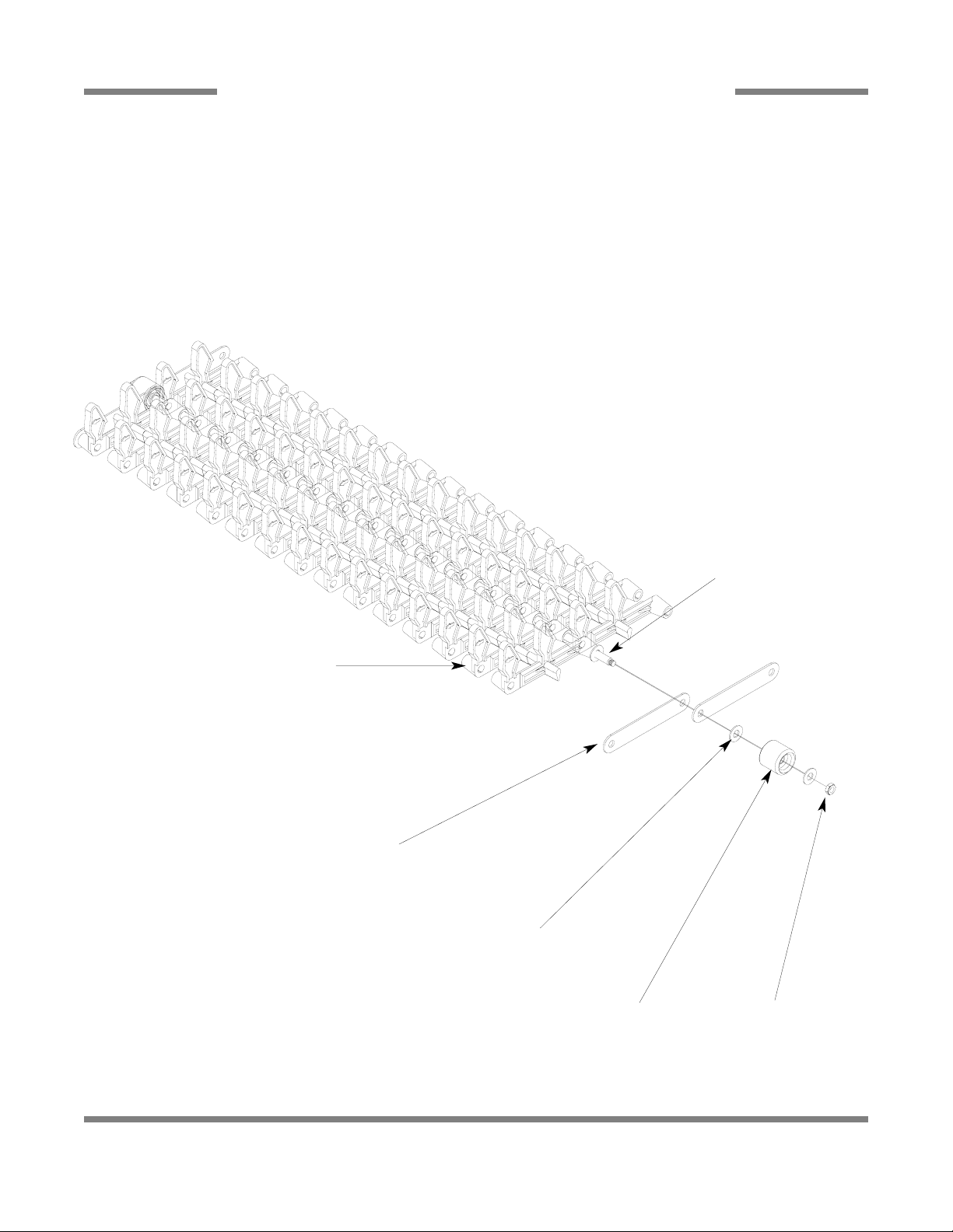
CONVEYOR BELT ASSEMBLY
When ordering replacement conveyor belt assemblies, please have your machine serial number available and contact Jackson
MSC, Inc. technical support toll free at 1-888-800-5672. Technical support is available from 8:00 a.m. to 5:00 p.m. (EST),
Monday through Friday. Technical support is not available on holidays. Your machine serial number can be found on the
machine data plate.
Complete 12 Foot Rod Assembly
05700-002-85-37
Peg, Belt
15 per assembly
05700-003-25-80
Plate, Connector
2 per assembly
05700-002-63-85
Washer
6 per assembly
05311-002-86-44
Wheel, PVC
2 per assembly
05340-002-63-86
Locknut, 1/4”-20, Low Profile
with Nylon Insert
2 per assembly
05310-374-02-00
Rod, Conveyor
1 per assembly
05700-002-63-92
PDF compression, OCR, web optimization using a watermarked evaluation copy of CVISION PDFCompressor
Page 9

41
PREWASH SECTION
PDF compression, OCR, web optimization using a watermarked evaluation copy of CVISION PDFCompressor
Page 10
JFT Series Technical Manual 7610-002-77-38
Issued: 03-16-2006 Revised: N/A
SECTION 6: PARTS SECTION
42
PREWASH SECTION ASSEMBLY
See Load Section
Shroud Assembly
Page
Cover, Back
05700-002-64-41
Foam, Back Cover
08115-002-71-33
Top Panel Cover
05700-002-64-40
Top Panel Handle
(not shown)
05700-002-67-21
See Curtain
Assembly Page
Gasket Spacers
Not Shown
Qty.: 38
05330-003-04-12
See Door Assembly Page
Prewash Arm Assembly
See Frame Assembly
Page
Control Box Assembly
See Drain Plumbing
Assembly
See Strainers Page
PDF compression, OCR, web optimization using a watermarked evaluation copy of CVISION PDFCompressor
Page 11
JFT Series Technical Manual 7610-002-77-38
Issued: 03-16-2006 Revised: N/A
43
SECTION 6: PARTS SECTION
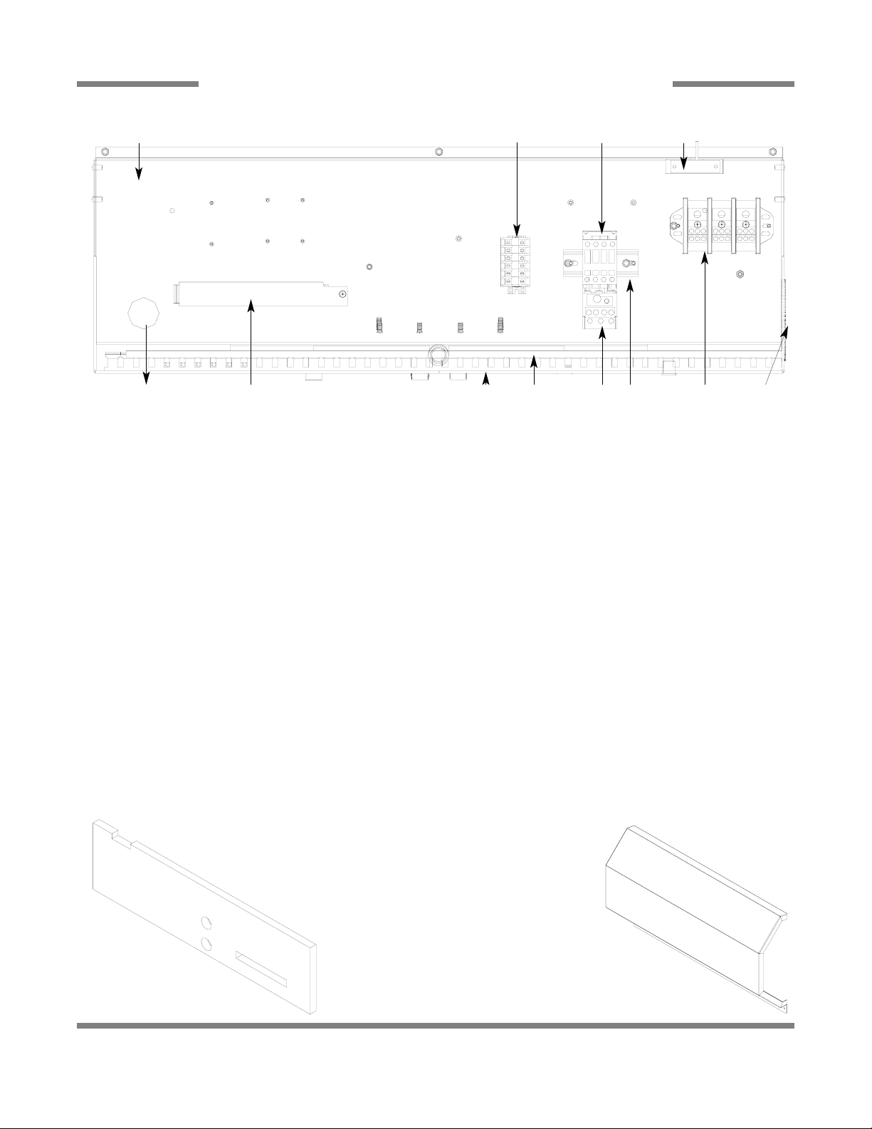
PREWASH SECTION - CONTROL BOX ASSEMBLY
1
5, 6, 7, 8
3
9
10
11
12
13 14 15
2
Insulation, Control Box
05700-002-80-47
Cover, Control Box Weldment, L-R
05700-002-88-27
Cover, Control Box Weldment, R-L
05700-002-88-28
Decal, Warning-Disconnect Power
09905-100-75-93
Decal, Drain Handle
05700-003-12-80
4
ITEM QTY DESCRIPTION Mfg. No.
1 1 Control Box Weldment 05700-002-70-62
2 1 Grommet, 3 1/2 Dia. Rubber 05700-002-83-05
3 1 Overload, Prewash Motor, 10 - 16 Amp, 208-230V Units 05945-011-84-59
3 1 Overload, Prewash Motor, 5.5-8.5 Amp, 460V Units 05945-111-68-40
3 1 Overload, Prewash Motor,4.0-6.3 Amp, 600V Units 05945-111-81-33
4 1 Sensor, Swing Arm Level 06680-002-98-62
5 1 Channel, Mounting 05700-002-83-23
6 6 Block, Terminal 05940-500-11-05
7 1 End Barrier 05940-500-21-05
8 1 Retaining Clip 05945-500-02-05
9 1 Contactor, Wash Motor 05945-111-68-38
10 1 Din Rail 05700-002-16-00
11 1 Switch, Reed 05930-002-36-80
12 1 Thermostat Cover 05700-002-70-61
13 1 Panduit Bottom 3” x 35 1/8” 05700-002-84-95
14 1 Panduit Cover 3” x 34” 05700-002-84-94
15 1 Block,Terminal 05940-011-48-27
PDF compression, OCR, web optimization using a watermarked evaluation copy of CVISION PDFCompressor
Page 12

JFT Series Technical Manual 7610-002-77-38
Issued: 03-16-2006 Revised: N/A
SECTION 6: PARTS SECTION
44
PREWASH SECTION - PREWASH ARM & DRAIN PLUMBING ASSEMBLIES
Wash Manifold Weldment
05700-002-96-95
Shield, Lower Wash Arm
05700-002-89-38
Bracket, Right, Locking Handle
05700-002-89-36
Bracket, Front Upper
Wash Arm Weldment
05700-002-89-97
Handle, Arm Locking Weldment
2 per
05700-002-89-93
Rail, Right Lower
Wash Arm Weldment
05700-002-90-54
Rail, Left Lower
Wash Arm Weldment
05700-002-90-53
Gasket, Wash Manifold Mounting
05330-002-89-84
Tube, Main Drain, 2 Per
05700-002-66-12
Drain Pump
Tube Assembly
05700-002-91-19
Bracket, Right, Locking Handle
05700-002-89-36
Bracket, Left, Locking Handle
05700-002-89-35
Gasket, Locking Handle
05330-002-89-94
Bracket, Left, Locking Handle
05700-002-89-35
Bracket, Front Lower
Wash Arm Weldment
05700-002-89-96
Shield, Upper Wash Arm
05700-002-89-37
Drain Cup Weldment
05700-002-73-72
Gasket, Drain Cup
05330-002-73-47
Wash Arm Assembly
2 per section
05700-002-65-45
Consists of items:
(1) Wash Arm Weldment
05700-002-83-51
(2) Cap, Threaded, 4 Per
04730-603-12-00
(3) Lanyard, 6” Long, 4 Per
05340-011-72-46
Complete Drain Plumbing Assembly
05700-002-79-16
Elbow, 1 1/2” Brass
04730-206-32-00
1 1/2” MNPT x 1 1/2” Slip
04730-002-74-06
Tube, Main Drain
05700-002-67-01
Tee, 2” PVC
04730-002-66-09
Connector, 2” No Hub,
2 Per
04730-002-66-87
1
2, 3
Valve, Ball, 1 1/2”
04820-111-71-46
Handle, Ball Valve
05700-002-98-10
4
2
1
Prewash Transfer Tube Assembly
05700-002-80-05
Consists of items:
(1) Valve, Brass Globe
04820-002-91-46
(2) Nipple, 1/2” Close Brass
04730-207-15-00
(3) Transfer Tube Weldment
05700-002-71-46
(4) Gasket, Final Rinse Plate
05330-002-67-61
3
PDF compression, OCR, web optimization using a watermarked evaluation copy of CVISION PDFCompressor
Page 13

45
WASH SECTION
PDF compression, OCR, web optimization using a watermarked evaluation copy of CVISION PDFCompressor
Page 14

JFT Series Technical Manual 7610-002-77-38
Issued: 03-16-2006 Revised: N/A
SECTION 6: PARTS SECTION
46
WASH SECTION ASSEMBLY
Cover, Back
05700-002-64-41
Foam, Back Cover
08115-002-71-33
Gasket Spacers
Qty.: 38
05330-003-04-12
Gasket, Tub
05700-002-86-10
Top Panel Cover
05700-002-64-40
Top Panel Handle
(not shown)
05700-002-67-21
See Curtain Assembly Page
See Door Assembly Page
Wash Arm Assembly
See Strainers Page
See Frame Assembly Page
See Motor Assemblies &
Heaters Page
(JFT-S Only) See Coil
Assembly Page
Control Box Assembly
See Drain Plumbing
Assembly Page
Hose Assembly, 65” Wash Steam Coil Supply
(JFT-S Only) (Not Shown)
05700-002-88-00
PDF compression, OCR, web optimization using a watermarked evaluation copy of CVISION PDFCompressor
Page 15

JFT Series Technical Manual 7610-002-77-38
Issued: 03-16-2006 Revised: N/A
SECTION 6: PARTS SECTION
47
WASH SECTION - CONTROL BOX ASSEMBLY
Insulation, Control Box
05700-002-80-47
11
1
13 14 15 16
18* 9
12
16 8
2
3
4 17* 10
Cover, Control Box
05700-002-81-82
Decal, Warning-Disconnect Power
09905-100-75-93
Decal, Drain Handle
05700-003-12-80
ITEM QTY DESCRIPTION Mfg. No.
1 1 Control Box Weldment 05700-002-70-62
2 1 Relay, 2 Pole 05945-111-35-19
3 1 Overload, Wash Motor, 10 - 16 Amp, 208-230V Units 05945-011-84-59
3 1 Overload, Wash Motor, 5.5-8.5 Amp, 460V Units 05945-111-68-40
3 1 Overload, Wash Motor, 4.0-6.3 Amp, 600V Units 05945-111-81-33
4 1 Thermostat 05930-003-16-65
Kit, Thermostat Replacement 06401-003-18-66
5 1 Channel, Mounting 05700-002-83-23
6 5 Block, Terminal 05940-500-11-05
7 1 End Barrier 05940-500-21-05
8 1 Sensor, Swing Arm Level 06680-002-98-62
9 1 Contactor, Wash Motor 05945-111-68-38
10 1 Din Rail 05700-002-16-00
11 1 Switch, Reed 05930-002-36-80
12 1 Thermostat Cover 05700-002-70-61
13 1 Panduit Bottom 05700-002-84-95
14 1 Panduit Cover 05700-002-84-94
15 1 Block,Terminal 05940-011-48-27
16 1 Grommet, 3 1/2 Dia. Rubber 05700-002-83-05
17* 2 Contactor, 3 Pole, 50 A (JFT Only) 05945-002-24-70
18* 2 Thermostat, High Limit (JFT Only) 05930-002-83-31
* Not used on steam unit.
PDF compression, OCR, web optimization using a watermarked evaluation copy of CVISION PDFCompressor
Page 16
JFT Series Technical Manual 7610-002-77-38
Issued: 03-16-2006 Revised: N/A
SECTION 6: PARTS SECTION
48
WASH SECTION - WASH ARM & DRAIN PLUMBING ASSEMBLY
Wash Manifold Weldment
05700-002-96-95
Shield, Lower Wash Arm
05700-002-89-38
Bracket, Right, Locking Handle
05700-002-89-38
Bracket, Front Upper
Wash Arm Weldment
05700-002-89-97
Handle, Arm Locking Weldment
2 per
05700-002-89-93
Rail, Right Lower
Wash Arm Weldment
05700-002-90-54
Rail, Left Lower
Wash Arm Weldment
05700-002-90-53
Gasket, Wash Manifold Mounting
05330-002-89-84
Tube, Main Drain, 2 Per
05700-002-66-12
Drain Pump Tube Assembly
05700-002-91-19
Bracket, Right, Locking Handle
05700-002-89-38
Bracket, Left, Locking Handle
05700-002-89-35
Gasket, Locking Handle
05330-002-89-94
Bracket, Left, Locking Handle
05700-002-89-35
Bracket, Front Lower
Wash Arm Weldment
05700-002-89-96
Shield, Upper Wash Arm
05700-002-89-37
Drain Cup Weldment
05700-002-73-72
Gasket, Drain Cup
05330-002-73-47
Wash Arm Assembly
2 per section
05700-002-65-45
Consists of items:
(1) Wash Arm Weldment
05700-002-83-51
(2) Cap, Threaded, 4 Per
04730-603-12-00
(3) Lanyard, 6” Long, 4 Per
05340-011-72-46
Complete Drain Plumbing Assembly
05700-002-79-16
Elbow, 1 1/2” Brass
04730-206-32-00
1 1/2” MNPT x 1 1/2” Slip
04730-002-74-06
Tube, Main Drain
05700-002-67-01
Tee, 2” PVC
04730-002-66-09
Connector, 2” No Hub
2 Per
04730-002-66-87
1
2, 3
Valve, Ball, 1 1/2”
04820-111-71-46
Handle, Ball Valve
05700-002-98-10
PDF compression, OCR, web optimization using a watermarked evaluation copy of CVISION PDFCompressor
Page 17

49
POWER RINSE SECTION
PDF compression, OCR, web optimization using a watermarked evaluation copy of CVISION PDFCompressor
Page 18

JFT Series Technical Manual 7610-002-77-38
Issued: 03-16-2006 Revised: N/A
SECTION 6: PARTS SECTION
50
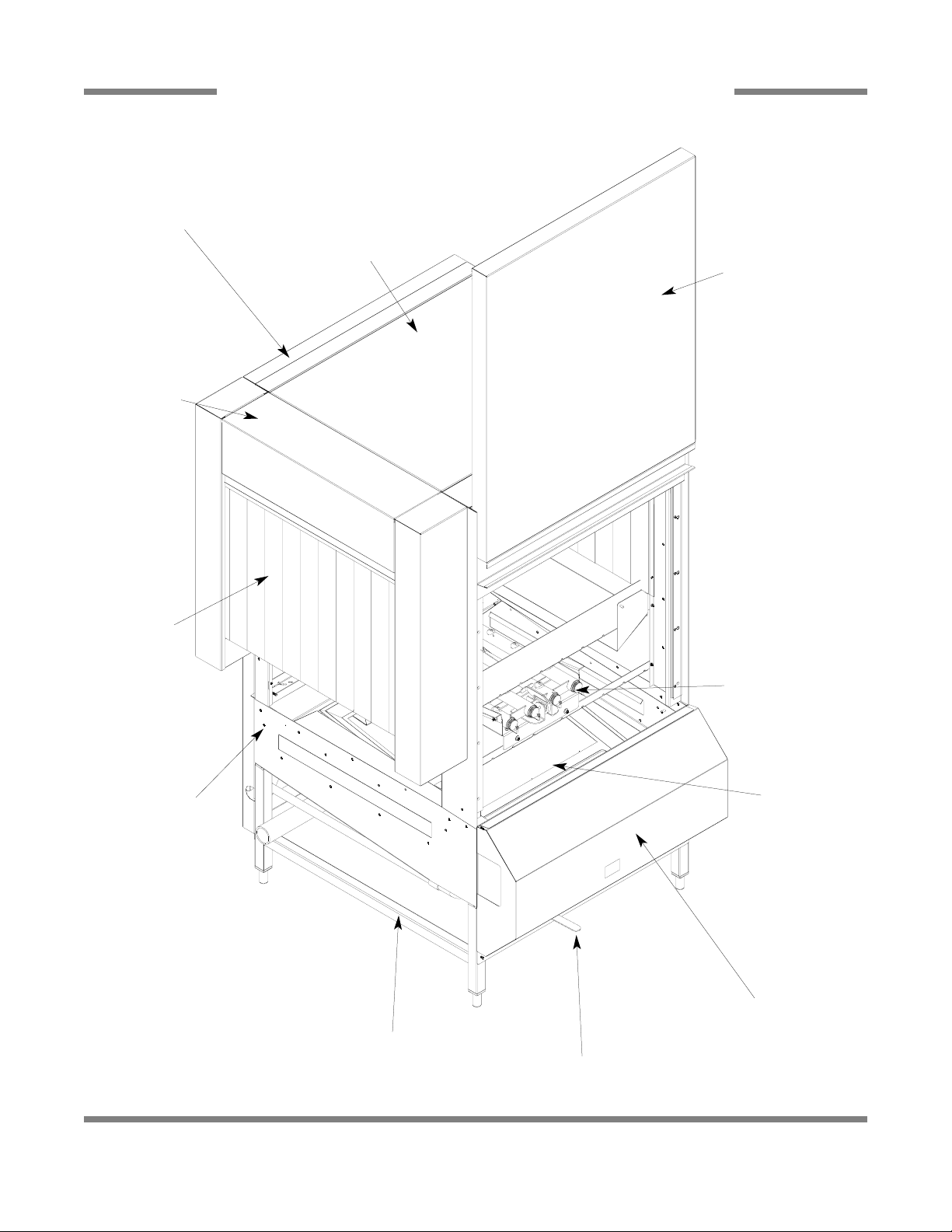
POWER RINSE SECTION ASSEMBLY
Cover, Back
05700-002-64-41
Foam, Back Cover
08115-002-71-33
Top Panel Cover
05700-002-64-40
Top Panel Handle
(not shown)
05700-002-67-21
See Curtain Assembly Page
See Door Assembly Page
Rinse Arm Assembly
See Strainers Page
See Frame Assembly Page
Gasket Spacers
Not Shown
Qty.: 38
05330-003-04-12
See Motor Assemblies &
Heaters Page
(JFT-S Only) See Coil
Assembly Page
Control Box Assembly
Drain Plumbing
Assembly
Hose Assembly, 21” Power Rinse Steam
Coil Supply (JFT-S Only) (Not Shown)
05700-002-88-01
Gasket, Tub
05700-002-86-10
PDF compression, OCR, web optimization using a watermarked evaluation copy of CVISION PDFCompressor
Page 19

JFT Series Technical Manual 7610-002-77-38
Issued: 03-16-2006 Revised: N/A
SECTION 6: PARTS SECTION
51
POWER RINSE SECTION - CONTROL BOX ASSEMBLY
Insulation, Control Box
05700-002-80-47
11
1
13 14 15 16
18* 9
12
16 8
2
3
4 17* 10
Cover, Control Box
05700-002-81-82
Decal, Warning-Disconnect Power
09905-100-75-93
Decal, Drain Handle
05700-003-12-80
ITEM QTY DESCRIPTION Mfg. No.
1 1 Control Box Weldment 05700-002-70-62
2 1 Relay, 2 Pole 05945-111-35-19
3 1 Overload, Wash Motor, 10 - 16 Amp, 208-230V Units 05945-011-84-59
3 1 Overload, Wash Motor, 5.5-8.5 Amp, 460V Units 05945-111-68-40
3 1 Overload, Wash Motor, 4.0-6.3 Amp, 600V Units 05945-111-81-33
4 1 Thermostat 05930-003-16-65
Kit, Thermostat Replacement 06401-003-18-66
5 1 Channel, Mounting 05700-002-83-23
6 5 Block, Terminal 05940-500-11-05
7 1 End Barrier 05940-500-21-05
8 1 Sensor, Swing Arm Level 06680-002-98-62
9 1 Contactor, Wash Motor 05945-111-68-38
10 1 Din Rail 05700-002-16-00
11 1 Switch, Reed 05930-002-36-80
12 1 Thermostat Cover 05700-002-70-61
13 1 Panduit Bottom 05700-002-84-95
14 1 Panduit Cover 05700-002-84-94
15 1 Block,Terminal 05940-011-48-27
16 1 Grommet, 3 1/2 Dia. Rubber 05700-002-83-05
17* 2 Contactor, 3 Pole, 50 A (JFT Only) 05945-002-24-70
18* 2 Thermostat, High Limit (JFT Only) 05930-002-83-31
* Not used on steam unit.
PDF compression, OCR, web optimization using a watermarked evaluation copy of CVISION PDFCompressor
Page 20

JFT Series Technical Manual 7610-002-77-38
Issued: 03-16-2006 Revised: N/A
SECTION 6: PARTS SECTION
52
POWER RINSE SECTION - RINSE ARM & DRAIN PLUMBING ASSEMBLIES
Wash Manifold Weldment
05700-002-96-95
Shield, Lower Wash Arm
05700-002-89-38
Bracket, Rinse Arm Orientation
05700-003-04-04
Gasket, Locking Handle
05330-002-89-94
Bracket, Front Upper
Wash Arm Weldment
05700-002-89-97
Handle, Arm Locking Weldment
2 per Prewash Arm Assembly
05700-002-89-93
Rail, Right Lower
Wash Arm Weldment
05700-002-90-54
Rail, Left Lower
Wash Arm Weldment
05700-002-90-53
Gasket, Wash Manifold Mounting
05330-002-89-84
Tube, Main Drain, 2 Per
05700-002-66-12
Drain Pump Tube Assembly
05700-002-91-19
Bracket, Rinse Arm Orientation
05700-003-04-04
Bracket, Left, Locking Handle
05700-002-89-35
Bracket, Left, Locking Handle
05700-002-89-35
Bracket, Front Lower
Wash Arm Weldment
05700-002-89-96
Shield, Upper Wash Arm
05700-002-89-37
Drain Cup Weldment
05700-002-73-72
Gasket, Drain Cup
05330-002-73-47
Power Rinse Arm Assembly
2 per section
05700-002-67-07
Consists of items:
(1) Rinse Arm Weldment
05700-002-83-83
(2) Cap, Threaded, 4 Per
04730-603-12-00
(3) Lanyard, 6” Long, 4 Per
05340-011-72-46
Complete Drain Plumbing Assembly
05700-002-79-16
Elbow, 1 1/2” Brass
04730-206-32-00
1 1/2” MNPT x 1 1/2” Slip
04730-002-74-06
Tube, Main Drain
05700-002-67-01
Tee, 2” PVC
04730-002-66-09
Connector, 2” No Hub
2 Per
04730-002-66-87
1
2, 3
Valve, Ball, 1 1/2”
04820-111-71-46
Handle, Ball Valve
05700-002-98-10
PDF compression, OCR, web optimization using a watermarked evaluation copy of CVISION PDFCompressor
Page 21

53
FINAL RINSE & ELECTRICAL SECTIONS
PDF compression, OCR, web optimization using a watermarked evaluation copy of CVISION PDFCompressor
Page 22

JFT Series Technical Manual 7610-002-77-38
Issued: 03-16-2006 Revised: N/A
SECTION 6: PARTS SECTION
54
FINAL RINSE ASSEMBLY (FOR MODELS WITH A PUMPED FINAL RINSE)
Complete Final Rinse Assembly
05700-002-67-36
Final Rinse Arm
2 per
05700-002-67-37
Elbow, 1/2” NPT 90° Brass
04730-011-42-96
Nut, 1/2” NSPT Brass
04730-002-67-88
Rinse Manifold Weldment
05700-002-67-50
Final Rinse Hose Assembly
05700-002-88-02
Gasket
05700-001-17-86
Rinse Arm Jet
14 per
04730-002-73-31
Rinse Arm Cap
2 per
05700-002-02-19
Runoff Sheet Weldment
05700-002-84-91
PDF compression, OCR, web optimization using a watermarked evaluation copy of CVISION PDFCompressor
Page 23

JFT Series Technical Manual 7610-002-77-38
Issued: 03-16-2006 Revised: N/A
SECTION 6: PARTS SECTION
55
FINAL RINSE ARM ASSEMBLY
Rinse Manifold Weldment
05700-002-67-50
Final Rinse Arm
2 per
05700-002-67-37
Rinse Arm Jet
14 per
04730-002-73-31
Gasket, Steam Coil
05700-001-17-86
Rinse Arm Cap
2 per
05700-002-02-19
PDF compression, OCR, web optimization using a watermarked evaluation copy of CVISION PDFCompressor
Page 24

JFT Series Technical Manual 7610-002-77-38
Issued: 03-16-2006 Revised: N/A
SECTION 6: PARTS SECTION
56
3/4” VACUUM BREAKER REPAIR PARTS KIT/AIR GAP ASSEMBLY
Components of Repair
Kit 06401-003-06-24
Cap Screw
Data Plate
Cap
O-Ring
Plunger
Body
Cap Retainer
Complete Vacuum Breaker Assembly
04820-002-53-77
Air Gap Assembly
05700-003-19-44
2
1
ITEM QTY DESCRIPTION Mfg. No.
1 2 Vacuum Breaker Assembly 04820-002-53-77
2 1 Fill Tube Weldment 05700-002-67-62
3 1 Fill Tube Weldment, 53-1/2” 05700-003-19-42
4 1 Elbow, 3/4”, 90° Brass 04730-206-13-00
5 1 Elbow, 1/2” NPT x 90 Deg. Brass 04730-011-42-96
6 1 Nut, Jam, 1/2” SPT 04730-002-67-88
7 1 Fill Tube Weldment 05700-003-07-10
8 1 Fill Tube Weldment, 56-1/2” 05700-003-19-40
9 1 Bushing, Hix 3/4” MNPT - 1/2” FNPT Brass 04730-002-56-27
Rinse Air Gap Assembly
05700-003-19-43
3
4
1
5
8
9
6
7
Service Note: If your model has the flex
hosing and needs serviced, please
contact Jackson Technial Service.
PDF compression, OCR, web optimization using a watermarked evaluation copy of CVISION PDFCompressor
Page 25

JFT Series Technical Manual 7610-002-77-38
Issued: 03-16-2006 Revised: N/A
SECTION 6: PARTS SECTION
57
ELECTRICAL SECTION ASSEMBLY
Latch, Door Compression
05340-002-80-97
Frame Assembly
05700-003-05-28
Gasket Spacers
Not Shown
Qty.: 38
05330-003-04-12
Rear Dress Panel
05700-002-72-53
Foam, Back Cover
08115-002-71-33
Lower Cover Weldment, L-R
05700-002-71-63
Lower Cover Weldment, R-L
05700-002-88-29
Electrical Control
Box Assembly
See Curtain
Assembly Page
See Final Rinse
Assembly Page
Rail Addition
Not Shown
05700-002-85-78
Vent Damper, 2 per
(Located beneath the
Exhaust Panel)
05700-002-83-78
Exhaust Panel Weldment
05700-002-99-23
No Pump Final Rinse
Assembly
05700-003-07-15
See Air Gap Assembly Page
Vent Exhaust Fan
06105-002-86-46
Adapter, Vent Weldment
05700-003-04-37
Top Panel Handle
05700-002-67-21
End Cap Panel Weldment
(not shown)
05700-002-70-99
PDF compression, OCR, web optimization using a watermarked evaluation copy of CVISION PDFCompressor
Page 26

JFT Series Technical Manual 7610-002-77-38
Issued: 03-16-2006 Revised: 09-13-2007
SECTION 6: PARTS SECTION
58
ELECTRICAL CONTROL BOX ASSEMBLY
HEATER
RINSE WASH PREWASH
7
45, 46
49, 50
47, 48
11
1
32
31
17***52*** 14
8
9
2
10
15
58
12
56
56
43, 44
13
18
6
33
34
35
41, 42
39, 40
5
30
**
36
37 38
16
1 3*
4*
39, 40
*Item not shown.
**Not used on the steam unit.
***Used on steam unit only.
PDF compression, OCR, web optimization using a watermarked evaluation copy of CVISION PDFCompressor
Page 27

*ltem not shown.
JFT Series Technical Manual 7610-002-77-38
Issued: 03-16-2006 Revised: N/A
SECTION 6: PARTS SECTION
59
ITEM QTY DESCRIPTION Mfg. No.
1 1 Terminal Board 05940-021-89-41
2 3 Relay, 2 Pole 05945-111-35-19
3* 2 Seal, Electrical Box Short (Not Shown) 05700-002-86-48
4* 2 Seal, Electrical Box Long (Not Shown) 05700-002-86-49
5 4 Block (Only 3 used on JFT-S) 05940-011-48-27
6 1 Transformer, 208-115V, 500VA, 208 unit 05950-002-95-32
6 1 Transformer, 240/480V-12, 5KVA, 240-460 unit 05950-002-46-10
7 1 Terminal Board 05940-002-78-97
8 1 Terminal Board, 8 Position 05940-021-94-85
9 2 Relay, 3 Pole 05945-111-72-51
10 1 Refer to page entitled Motor Overloads N/A
11** 1 Contactor, 3 Pole, 50A(JFT Only) 05945-002-24-70
12 5 Contactor, Wash Motor 05945-111-68-38
13 1 Refer to page entitled Motor Overloads N/A
14 2 Refer to page entitled Motor Overloads N/A
15 1 Din Rail, 10 7/8” 05700-002-93-96
16 4 Ground Lug (Only 3 used on JFT-S) 05940-200-76-00
17*** 1 Steam Pressure Gauge, 0-60 06685-002-93-43
18 1 Refer to page entitled Motor Overloads N/A
19a 1 Decal, Flight Control Panel (Jackson) (Not Shown) 09905-002-97-87
20 1 Light, Green 05945-002-80-79
21 1 Light, Amber 05945-002-80-83
22 1 Switch, Stop 05930-002-80-73
23 1 Switch, ON/FILL Heat 05930-002-80-59
24 1 Switch, Start 05930-002-80-60
25 1 Switch, OFF/FILL Heat 05930-002-80-69
26 1 Switch, Emergency Stop 05930-002-80-72
27 1 Switch, Speed 05930-002-80-74
28 1 Gauge, Cyclic (Temperature) 06685-002-74-86
29 1 Gauge Cover 05700-002-75-62
ELECTRICAL CONTROL BOX ASSEMBLY (CONTINUED)
19
24
27
28, 2922
20
23
25
21
26
*Item not shown.
**Not used on the steam unit.
***Used on steam unit only.
**Not used on the steam unit.
***Used on steam unit only.
SECTION 6: PARTS SECTION
ELECTRICAL CONTROL BOX ASSEMBLY (CONTINUED)
19
23
25
20 21 26
24
27
22 28, 29
ITEM QTY DESCRIPTION Mf g. No.
2 3 Relay, 2 Pole 05945-111-35-19
3*
4*
5 4
6 1 Transformer, 208-115v, 500VA, 208 unit 05950-002-95-32
6 1 Transformer, 240/480V-12, 5KVA, 240-460 unit 05950-002-46-10
7 1
8 1 Terminal Board, 8 Position 05940-02 1 -94-85
9 2 Relay, 3 Pole 05945-111-72-51
10 1 Refer to page entitled Motor Overloads N/A
11**
12 5 Contactor, Wash Motor 05945-111-68-38
13 1 Refer to page entitled Motor Overloads
14 2
15 1 Din Rail, 107/8" 05700-002-93-96
16 4 Ground Lug (Only 3 used on JFT-S) 05940-200-76-00
17***
18 1
19a 1 Decal, Flight Control Panel (Jackson) (Not Shown) 09905-002-97-87
20 1 Light, Green 05945-002-80-79
21 1
22 1 Switch, Stop 05930-002-80-73
23 1 Switch, ON/FILL Heat 05930-002-80-59
24 1 Switch, Start 05930-002-80-60
25 1
26 1 Switch, Emergency Stop 05930-002-80-72
27 1 Switch, Speed 05930-002-80-74
28 1 Gauge, Cyclic (Temperature) 06685-002-74-86
29 1
1
2 Seal, Electrical Box Short (Not Shown) 05700-002-86-48
2 Seal, Electrical Box Long (Not Shown) 05700-002-86-49
1
1 Steam Pressure Gauge, 0-60 06685-002-93-43
Terminal Board
Block (Only 3 used on JFT-S)
Terminal Board
Contactor, 3 Pole, 50A (JFT Only)
05940-02 1 -89-41
05940-011 -48-27
05940-002-78-97
05945-002-24-70
N/A
Refer to page entitled Motor Overloads N/A
Refer to page entitled Motor Overloads N/A
Light, Amber
Switch, OFF/FILL Heat
Gauge Cover
05945-002-80-83
05930-002-80-69
05700-002-75-62
JFT Series Technical Manual 761 O-002-77-38
Issued: 03-16-2006 Revised: N/A
59
PDF compression, OCR, web optimization using a watermarked evaluation copy of CVISION PDFCompressor
Page 28

JFT Series Technical Manual 7610-002-77-38
Issued: 03-16-2006 Revised: 10-11-07
SECTION 6: PARTS SECTION
60
ITEM QTY DESCRIPTION Mfg. No.
30 1 Hinge, Upper Control Box 05700-002-70-45
31 1 Hinge, Lower Control Box 05700-002-71-59
32 1 Fuse Holder 05920-401-03-14
33 1 Bracket, Circuit Breaker Mounting 05700-002-91-66
34 1 Fuse Holder 05920-011-72-89
35 1 Fuse, 2A, 460V (208-240V units) 05920-002-67-30
35 1 Fuse, 1A, 460V (460-600V units) 05920-002-67-23
36 4 Decal, Connection Point Caution (Only 3 used on JFT-S) 09905-002-87-00
37 4 Decal, Connection Point Wiring (Only 3 used on JFT-S) 09905-002-87-01
38 4 Decal, L1, L2, L3 (Only 3 used on JFT-S) 09905-101-12-66
39 2 Top, Panduit 1 1/2” x 8” 05700-002-87-28
40 2 Bottom, Panduit 1 1/2” x 8” 05700-002-91-61
41 1 Top, Panduit 1 1/2” x 11” 05700-002-87-27
42 1 Bottom, Panduit 1 1/2” x 11” 05700-002-87-26
43 1 Top, Panduit 1 1/2” x 18 1/4” 05700-002-91-62
44 1 Bottom, Panduit 1 1/2” x 18 1/4” 05700-002-91-63
45 1 Top, Panduit 1 1/2” x 20 3/4” 05700-002-87-24
46 1 Bottom, Panduit 1 1/2” x 20 3/4” 05700-002-87-25
47 1 Top, Panduit 1 1/2” x 22 1/2” 05700-002-87-23
48 1 Bottom, Panduit 1 1/2” x 22 1/2” 05700-002-87-20
49 2 Top, Panduit 3” x 28” 05700-002-87-30
50 2 Bottom, Panduit 3” x 28” 05700-002-87-29
51 1 Key, Control Box 5/16 Hex 05340-002-94-50
52*** 1 Thermostat, Corkscrew (Note: Placed in control box in upside down postion) 06680-500-01-77
53* 3 Plug, Female 24 Position 05935-002-93-15
54* 1 Transformer, 600-208V, 3KVA, 600V unit (Used for the drive, blower, and exhaust fan) 05950-002-94-68
55* 1 Transformer, 600-120V, .5KVA, 600V unit (Used for controls) 05950-002-94-98
56 2 Delay Timer (Uses 2 for a unit with a blower) 05945-011-65-44
1 Din Rail 05700-002-16-00
57* 1 Grommet, 34 1/2” Assembly 05700-003-12-00
58 1 Water Pressure Gauge, 0-100 06685-011-86-42
59* 1 Brace, control Box Door 05700-003-24-58
60* 4 Button Guard, Control Box 05700-003-23-24
*Item not shown.
**Not used on the steam unit.
***Used on steam unit only.
ELECTRICAL CONTROL BOX ASSEMBLY (CONTINUED)
PDF compression, OCR, web optimization using a watermarked evaluation copy of CVISION PDFCompressor
Page 29

JFT Series Technical Manual 7610-002-77-38
Issued: 03-16-2006 Revised: N/A
SECTION 6: PARTS SECTION
61
Optional
JFT Prewash Motor Wash Motor Rinse Motor Final Rinse Motor
208V, 60HZ, 3PH 05945-011-84-59 05945-011-84-59 05945-111-68-40 05945-111-68-41
240V, 60HZ, 3PH 05945-011-84-59 05945-011-84-59 05945-111-68-40 05945-111-68-41
460V, 60HZ, 3PH 05945-111-68-40 05945-111-68-40 05945-111-68-41 05945-111-69-13
600V, 60HZ, 3PH 05945-111-69-13 05945-111-69-13 05945-111-69-12 05945-111-68-39
JFT
Drive Motor Exhaust Fan Motor Blower Dryer Motor
208V, 60HZ, 3PH 05945-111-69-13 05945-111-68-39 05945-111-68-40
240V, 60HZ, 3PH 05945-111-69-13 05945-111-68-39 05945-111-68-40
460V, 60HZ, 3PH 05945-002-71-09 05945-111-69-12 05945-111-68-41
600V, 60HZ, 3PH 05945-111-68-39 05945-111-68-39 05945-111-68-40
Optional
JFT
-S Prewash Motor Wash Motor Rinse Motor Final Rinse Motor
208V, 60HZ, 3PH 05945-011-84-59 05945-011-84-59 05945-111-68-40 05945-111-68-41
240V, 60HZ, 3PH 05945-011-84-59 05945-011-84-59 05945-111-68-40 05945-111-68-41
460V, 60HZ, 3PH 05945-111-68-40 05945-111-68-40 05945-111-68-41 05945-111-69-13
600V, 60HZ, 3PH 05945-111-69-13 05945-111-69-13 05945-111-69-12 05945-111-68-39
JFT
-S Drive Motor Exhaust Fan Motor Blower Dryer Motor
208V, 60HZ, 3PH 05945-111-69-13 05945-111-68-39 05945-111-68-40
240V, 60HZ, 3PH 05945-111-69-13 05945-111-68-39 05945-111-68-40
460V, 60HZ, 3PH 05945-002-71-09 05945-111-69-12 05945-111-68-41
600V, 60HZ, 3PH 05945-111-69-13 05945-111-68-39 05945-111-68-40
MOTOR OVERLOADS CHART
PDF compression, OCR, web optimization using a watermarked evaluation copy of CVISION PDFCompressor
Page 30

JFT Series Technical Manual 7610-002-77-38
Issued: 03-16-2006 Revised: N/A
SECTION 6: PARTS SECTION
62
JFT ELECTRICAL SECTION - BOOSTER HEATER & FRAME ASSEMBLY
3
4
6
5
7
1
2
9
10 11
128
13 18
19
17
16
152014
PDF compression, OCR, web optimization using a watermarked evaluation copy of CVISION PDFCompressor
Page 31

JFT Series Technical Manual 7610-002-77-38
Issued: 03-16-2006 Revised: 12-18-06
SECTION 6: PARTS SECTION
63
ITEM QTY DESCRIPTION Mfg. No.
1 1 Stand, Weldment 05700-002-70-51
2 4 Bullet Foot 05340-108-02-06
3 4 Support Bracket 05700-002-64-07
4 1 Panel, Dryer Lower Left 05700-002-72-04
5 1 Panel, Dryer Lower Right 05700-002-90-40
6 1 Bracket, Conduit Electrical Section 05700-002-86-96
7 1 Heater, 27KW, 208V, 3PH Booster 04540-500-05-00
7 1 Heater, 27KW, 240V, 3PH Booster 04540-500-02-00
7 1 Heater, 27KW, 460V, 3PH Booster 04540-500-12-00
7 1 Heater, 45KW, 600V, 3PH Booster 04540-002-94-73
8 2 Clip, Panel 05700-002-90-41
9 1 Temperature Probe 06680-002-16-80
10 1 Fitting, Imperial Brass 05310-924-02-05
11 1 Fitting, Thermostat Booster Heater 05700-002-93-74
12 1 Tee, 3/4” x 3/4” x 3/4” NPT Brass 04730-211-01-34
13 1 Bushing, Hex 3/4” MNPT x 1/2” FNPT Brass 04730-002-56-27
14 1 Nipple, Close 1/2” Brass 04730-207-15-00
15 1 Tee, 1/2” x 1/2” x 1/4” FNPT Brass 04730-002-22-56
16 1 Bushing, 1/4” x 1/8” Stainless 04730-003-05-61
17 1 Valve, Check 04820-111-51-14
18 1 Outlet Elbow Ftg. 04820-111-51-18
19 1 Nut, P/P For 1/8” Tubing 04730-011-59-45
20 1 Elbow, 3/4” 90° NPT Brass 04730-206-13-00
JFT ELECTRICAL SECTION - BOOSTER HEATER & FRAME ASSEMBLY (CONTINUED)
PDF compression, OCR, web optimization using a watermarked evaluation copy of CVISION PDFCompressor
Page 32

JFT Series Technical Manual 7610-002-77-38
Issued: 03-16-2006 Revised: N/A
SECTION 6: PARTS SECTION
64
JFT-S ELECTRICAL SECTION - STEAM BOOSTER ASSEMBLY
Please refer to previous pages for
parts related to the frame.
4
44
36
37
38
48
39
26
25
28
42
43
34
33
27
35
29, 5
13
13
1
2
31
30
20
20
30
19
45
10
40
11
32
22
3
7
6
31
43
15
18
23
12 32
14
14
17
41
13
8
32
12
16
13
12
24
9
Bottom View of Steam Booster
19
46 47
20
21
24
PDF compression, OCR, web optimization using a watermarked evaluation copy of CVISION PDFCompressor
Page 33

JFT Series Technical Manual 7610-002-77-38
Issued: 03-16-2006 Revised: N/A
65
ITEM QTY DESCRIPTION Mfg. No.
1 1 Hose Assembly, 34” Supply (Not Shown) 05700-002-87-99
2 1 Hose Assembly, 65” Wash Steam Coil Supply (Not Shown) 05700-002-88-00
3 1 Hose Assembly, 21” Power Rinse Steam Coil Supply (Not Shown) 05700-002-88-01
4 1 Hose Assembly, 1/2” x 50” Final Rinse (Not Shown) 05700-002-88-02
5 1 Hose Assembly, 109” Booster Heater Supply(Not Shown) 05700-002-88-05
6 1 Heat Exchanger, Steam M-120 04420-002-43-94
7 3 Valve, Solenoid, Steam 120V, 3/4” 04820-011-87-39
8 1 Valve, Safety Relief 1” NPT 04820-100-01-35
9 1 Valve, Solenoid, 1” 04820-002-92-23
10 1 Bracket, Steam Support 05700-002-86-93
11 1 Elbow, Street, 1” Black Iron 04730-002-86-58
12 3 Elbow, 1” NPT 90° Black Iron 04730-906-03-34
13 5 Nipple, 1” NPT, Close Black Iron 04730-907-08-34
14 2 Tee, 1” x 1” x 1”, Black Iron 04730-911-01-34
15 1 Nipple, Pigtail, 1/4” NPT Black Iron 04730-907-14-34
16 1 Union, 1” Black Iron 04730-912-01-34
17 1 Y-Strainer, 1” NPT Black Iron 04730-217-02-32
18 1 Reducer, 1” to 3/4” 04730-011-95-66
19 2 Elbow, 3/4” NPT 90° Street 04730-011-87-37
20 4 Nipple, Close 3/4” Black Iron 04730-907-01-00
21 1 Bushing, 1 1/2” x 3/4” Black Iron 04730-002-36-81
22 1 Bushing, 1 1/2” MNPT x 1” FNPT Black Iron 04730-002-36-79
23 1 Tee, 1” x 1” x 1/4” Black Iron 04730-911-01-00
24 1 Steam Trap, 3/4” NPT (F & T Type) 06680-500-02-77
25 2 Bushing, Hex 1 1/4” 3/4” Reducer 04730-011-88-80
26 3 Nipple, 3/4” NPT Close Brass Nipple 04730-207-34-00
27 2 Tee, 3/4” x 3/4” x 3/4” NPT Brass 04730-211-01-34
28 1 Bushing, 3/4” MNPT x 3/8” FNPT Brass 04730-011-89-19
29 1 Elbow, 3/4” Street Brass 90° 04730-206-04-34
30 2 Tee, 3/4” x 3/4” x 3/4” NPT Black Iron 04730-002-74-14
31 3 Nipple, 3/4” x 4” Black Iron 04730-907-02-34
32 4 Nipple, 1” NPT x 4” Long, Black Iron 04730-907-09-34
33 1 Fitting, Thermostat Weldment 05700-002-93-74
34 1 Tee, 3/4” x 3/4” x 1/4” NPT Brass 04730-211-04-00
35 1 Bushing, Hex 3/4” MNPT x 1/2” FNPT Brass 04730-002-56-27
36 1 Valve, Check 04820-111-51-14
37 1 Nut, P/P For 1/8” Tubing 04730-011-59-45
38 1 Fitting, Outlet Elbow 04820-111-51-18
39 1 Fitting, 1/4” Imperial Brass 05310-924-02-05
40 1 Probe, Temperature 06680-002-16-80
41 2 Bolt, U Type 1/2”-13 05306-002-89-27
42 1 Hose, SS Braid 04720-002-93-78
43 2 Elbow, 90° 1/4” FNPT Black Iron 04730-002-87-10
44 1 Elbow, 1/2” NPT 90° Street 04730-206-08-00
45 1 Elbow, 3/4” NPT 90° Black Iron 04730-906-10-34
46 1 Nipple, 3/4” NPT x 14 3/4” Long, Black Iron 05700-002-21-22
47 1 Union, 3/4” Black Iron 04730-912-01-01
48 1 Bushing, 1/4” x 1/8” Stainless 04730-003-05-61
SECTION 6: PARTS SECTION
JFT-S ELECTRICAL SECTION - STEAM BOOSTER ASSEMBLY (CONTINUED)
Bracket, Conduit Steam Electric Section
05700-002-98-87
Panel, Lower Steam Electric Section
05700-002-86-97
PDF compression, OCR, web optimization using a watermarked evaluation copy of CVISION PDFCompressor
Page 34

66
BLOWER DRYER SECTION
PDF compression, OCR, web optimization using a watermarked evaluation copy of CVISION PDFCompressor
Page 35

JFT Series Technical Manual 7610-002-77-38
Issued: 03-16-2006 Revised: N/A
SECTION 6: PARTS SECTION
67
BLOWER DRYER SECTION ASSEMBLY
Blower Assembly , JFT
05700-002-70-21
Blower Assembly , JFT-S
05700-002-76-86
Lower Cover Weldment, L-R
05700-002-71-63
Lower Cover Weldment, R-L
05700-002-88-29
Steam Trap
(JFT-S Only) (Not Shown)
06680-002-86-73
Nipple, Close 3/4” Black Iron
(JFT-S Only) (Not Shown)
04730-907-01-00
Hose, Blower Steam Trap Assembly
(JFT-S Only) (Not Shown)
05700-002-87-97
Nipple, Close 3/4” Black Iron
(JFT-S Only) (Not Shown)
04730-907-01-00
Elbow, 3/4” NPT 90° Street, Black Iron
(JFT-S Only) (Not Shown)
04730-011-87-37
Front Panel Weldment
05700-002-88-26
Hose, Blower Section
Inlet Assembly
(JFT-S Only) (Not Shown)
05700-002-87-98
Nipple, Close 3/4” Black Iron
(JFT-S Only) (Not Shown)
04730-907-01-00
Elbow, 3/4” NPT 90° Street,
Black Iron
(JFT-S Only) (Not Shown)
04730-011-87-37
Frame Assembly
05700-002-86-26
Baffle, Lower Blower Air
05700-002-84-92
Cover, Back
05700-002-64-41
Rail Addition
2 per (Not Shown)
05700-002-85-78
Dish Stabilizers (3 per)
05330-003-04-43
Blower Air Knives Box Weldment
05700-002-70-21
Stabilizer Bracket (3 per)
05330-003-04-44
PDF compression, OCR, web optimization using a watermarked evaluation copy of CVISION PDFCompressor
Page 36

JFT Series Technical Manual 7610-002-77-38
Issued: 03-16-2006 Revised: N/A
SECTION 6: PARTS SECTION
68
JFT BLOWER ASSEMBLY
Panel, Blower Dryer Top
05700-002-72-00
Panel, Blower Side
05700-002-71-99
Blower, 208-230/600V, 60HZ, Dual Cage
06105-002-72-15
Blower, 460V, 60HZ, Dual Cage
06105-002-88-36
JFT Heater, 4.5 KW, 208V, Blower Air, 2 Per
04540-002-74-29
JFT Heater, 4.5 KW, 240V, Blower Air, 2 Per
04540-002-87-79
JFT Heater, 4.5 KW, 460V, Blower Air, 2 Per
04540-002-91-60
JFT Heater, 4.5 KW, 600V, Blower Air, 2 Per
04540-002-90-30
Frame, Blower Dryer
Support Assembly
05700-002-84-68
Blower Dryer Heater Box Weldment, JFT
05700-002-72-14
Blower Dryer Heater Box Weldment, JFT-S
05700-002-76-85
Panel, Blower Dryer Front & Back
05700-002-71-98
Panel, Blower Dryer Side
05700-002-71-99
Panel, Blower Dryer
Front & Back
05700-002-71-98
The JFT-S uses the following components in place of the heaters used on the JFT.
Heat Exchanger, Blower
04420-002-76-68
Elbow, 3/4” NPT 90° Street, Brass
1 per hose assembly
04730-206-04-34
Hose Assembly , Inlet
05700-002-87-96
Elbow, 3/4” NPT 90° Street, Brass
2 per heat exchanger
04730-206-04-34
Hose Assembly , Outlet
05700-002-87-95
Nipple, 3/4” x 2” Brass
2 per heat exchanger
04730-207-46-00
High Limit Thermostat
05930-002-83-31
PDF compression, OCR, web optimization using a watermarked evaluation copy of CVISION PDFCompressor
Page 37

69
UNLOAD EXPANSION &
UNLOAD SECTION(S)
PDF compression, OCR, web optimization using a watermarked evaluation copy of CVISION PDFCompressor
Page 38

JFT Series Technical Manual 7610-002-77-38
Issued: 03-16-2006 Revised: N/A
SECTION 6: PARTS SECTION
70
UNLOAD SECTION EXPANSION ASSEMBLIES
Rail Guard, Upper Weldment
2 per
05700-002-85-58
Rail, Lower
4 per
05700-002-65-07
Frame Assembly
2 per (consists of*)
05700-002-86-07
* Bullet Foot
2 per
05340-108-02-06
Panel,Dress
2 per assembly
05700-002-85-52
* Frame Weldment
05700-002-67-84
STRAIGHT EXPANSION SECTION
ANGLED EXPANSION SECTION
Rail Guard Angled Weldment
05700-002-85-55
Panel, Dress
05700-002-85-52
* Frame Weldment
05700-002-67-84
Frame Assembly
2 per (consists of*)
05700-002-86-07
Rail Guard Angled Weldment
05700-002-85-56
Panel, Dress
05700-002-85-52
* Bullet Foot
2 per
05340-108-02-06
PDF compression, OCR, web optimization using a watermarked evaluation copy of CVISION PDFCompressor
Page 39

JFT Series Technical Manual 7610-002-77-38
Issued: 03-16-2006 Revised: N/A
SECTION 6: PARTS SECTION
71
UNLOAD SECTION 18” EXPANSION ASSEMBLY
Rail Guard, Upper Weldment
2 per
05700-003-15-43
Frame Assembly
2 per (consists of*)
05700-002-86-07
* Frame Weldment
05700-002-67-84
* Bullet Foot
2 per
05340-108-02-06
Gasket Spacer
16 per
05330-003-04-12
Rail, Lower
4 per
05700-002-65-07
Panel,Dress
05700-003-15-42
PDF compression, OCR, web optimization using a watermarked evaluation copy of CVISION PDFCompressor
Page 40

JFT Series Technical Manual 7610-002-77-38
Issued: 03-16-2006 Revised: N/A
SECTION 6: PARTS SECTION
72
UNLOAD END ASSEMBLY
Slide Stop Assembly
(Made up of *)
05700-002-82-16
*Cover Weldment
05700-002-82-15
*Slide Stop Weldment
05700-002-82-14
*Slide Stop Finger
14 Per
05700-002-82-13
*Magnet
05930-002-88-42
*Spring
2 Per
05340-002-90-39
*Bracket, Right
05700-002-97-54
* Bracket, Left
05700-002-97-55
Panel End Weldment
05700-002-84-65
Key, Drive Wheel
05700-002-94-87
Set Screw
05305-002-10-14
Key, Drive Wheel
05700-002-94-87
Set Screw
05305-002-10-14
Belt, Gear Large
06105-002-75-22
Chain, Drive Motor
05700-002-88-43
Belt, Gear Small
06105-002-75-21
Panel, Dress
2 Per
05700-002-83-95
Rail, Upper Front
2 per
05700-002-69-11
Rail, Lower Front
2 per
05700-002-69-12
Switch, Green Start
05930-002-80-60
Heyco Plug
See insert below for new style.
2 per
05975-011-47-81
Cover, Switch
See insert below for new style
05700-002-79-85
Cover, Switch
05700-003-09-10
Bracket, Switch Holding
05700-003-09-11
Snap Bushing
05975-003-10-46
Switch, Red Stop
05930-002-80-73
Domed Plug
2 per
05975-003-10-45
Switch holding braket with new recessed switches.
PDF compression, OCR, web optimization using a watermarked evaluation copy of CVISION PDFCompressor
Page 41

JFT Series Technical Manual 7610-002-77-38
Issued: 03-16-2006 Revised: N/A
SECTION 6: PARTS SECTION
73
UNLOAD END ASSEMBLY (CONTINUED)
19
ITEM QTY DESCRIPTION Mfg. No.
1 1 Drive Motor Support Bracket 05700-002-84-66
2 2 Bolt, Spring Holding, 3/8” 05700-002-82-62
2 Spring 05340-002-87-02
3 1 Drive Motor Mounting Bracket 05700-002-82-45
4 1 Drive Motor Assembly (600 Volt) 05700-002-95-62
4 1 Drive Motor Assembly (460 Volt) 05700-002-68-55
4 1 Drive Motor Assembly (208-240 Volt) 05700-002-66-38
1 Gear Drive 06105-002-68-52
1 Drive Motor (208/230 Volt Models) 06105-002-87-69
1 Drive Motor (460 Volt Models) 06105-002-87-70
1 Drive Motor (600 Volt Models) 06105-002-87-71
5 1 Belt Centering Plate 05700-002-82-08
6 1 Drive Wheel 05700-002-67-03
7 1 Drive Rod 05700-002-75-13
8 1 Bearing, Two-Bolt Mounting Flange 03120-002-69-31
9 1 Magnet (Not Shown) 05930-002-88-42
10 1 Reed Switch 05930-002-36-80
11 1 Limit Switch Mounting Bracket 05700-011-71-18
12 1 Pin, Drive Plate Weldment 05700-002-92-06
1 Conduit Box (Not Shown) 05700-002-93-09
1 Conduit Box Top (Not Shown) 05700-002-93-10
2
3
4
5 6
7
8
10,
11
12
PDF compression, OCR, web optimization using a watermarked evaluation copy of CVISION PDFCompressor
Page 42

JFT Series Technical Manual 7610-002-77-38
Issued: 03-16-2006 Revised: N/A
SECTION 6: PARTS SECTION
74
UNLOAD END MISCELLANEOUS ASSEMBLIES
4, 5
12
15
13
14
18a
18b
18c
18d
18e
10
11
6
16
7
18g
18f
3
8b
8a
8c
2
1
9
ITEM QTY DESCRIPTION Mfg. No.
1 2 Frame Weldment 05700-002-67-84
2 4 Bullet Foot 05340-108-02-06
3 1 Plate, Slide Rinse Weldment 05700-002-88-51
4 1 Rinse Tank Weldment 05700-002-88-50
PDF compression, OCR, web optimization using a watermarked evaluation copy of CVISION PDFCompressor
Page 43

JFT Series Technical Manual 7610-002-77-38
Issued: 03-16-2006 Revised: 10-11-2007
75
ITEM QTY DESCRIPTION Mfg. No.
5 1 Rinse Tank Cover (Not Shown) 05700-003-05-43
6 1 Swing Arm Sensor 05700-002-98-62
7 1 Motor, 1/2 HP, 208-230V 06105-002-72-71
7 1 Motor, 1/2 HP, 460V 06105-002-72-71
7 1 Motor, 1/2 HP, 600V 06105-002-90-34
8 1 Plumbing, Rinse Motor 05700-002-85-64
8a 1 Bushing, Brass 1” FNPT x 3/4” MNPT 04730-011-65-14
8b 1 Elbow, 3/4” Street Brass 04730-206-04-34
8c 1 Restrictor, Rinse Pump Discharge 05700-002-90-35
9 1 Hose Assembly, 109” Booster Heater Supply 05700-002-88-05
10 1 Rod, Float Formed 05700-003-05-58
11 1 Ball Float 06680-003-05-56
12 1 Valve, Float 1/2” Brass 06680-003-05-46
13 1 Nut, 1/2” NPT Brass 04730-208-03-00
14 1 Adapter, 1/2” NPT x C Male 04730-401-07-01
15 1 Elbow, 1/2” NPT 90 Deg. Brass 04730-011-42-96
16 1 Hose Assembly, 24” Solenoid to Final Rinse Tank 05700-002-88-04
17 1 Hose Assembly, 90” Machine Fill 05700-002-88-03
18 1 Plumbing, Solenoid Assembly 05700-002-85-62
18a 1
Y-Strainer, 3/4” 04730-717-02-06
18b 3 Nipple, 3/4” Close Brass 04730-207-34-00
18c 5 Elbow, 3/4” Street 04730-206-04-34
18d 1 Tee, Brass 3/4” x 3/4” x 3/4” 04730-211-01-34
18e 2 Valve, 120V Solenoid 04810-002-83-15
18f 1 Bushing, Hex 3/4” to 1/2” 04730-002-56-27
18g 1 Regulator, 3/4” Pressure 06685-011-58-22
SECTION 6: PARTS SECTION
UNLOAD END MISCELLANEOUS ASSEMBLIES (CONTINUED)/SLIDE STOPASSEMBLY
Lanyard, Slide Stop Weldment
05700-003-21-84
Locknut, 1/4”-20 Hex W/Nylon Insert
4 Per
05310-374-01-00
Screw, 1/4”-20 x 5/8” Truss Phillips Head
2 Per
05305-174-04-00
Bolt, 1/4”-20 x 1/2” Long
2 Per
05305-274-02-00
Chain 1/8 x 20 Links
05700-003-21-83
Washer, 1/4-20 I.D. S/S
2 Per
05311-174-01-00
PDF compression, OCR, web optimization using a watermarked evaluation copy of CVISION PDFCompressor
Page 44

76
COMMON PARTS & ASSEMBLIES
PDF compression, OCR, web optimization using a watermarked evaluation copy of CVISION PDFCompressor
Page 45

JFT Series Technical Manual 7610-002-77-38
Issued: 03-16-2006 Revised: 10-11-2007
SECTION 6: PARTS SECTION
77
MOTOR ASSEMBLIES & JFT HEATERS
Other motor parts not shown:
ITEM QTY DESCRIPTION Mfg. No.
* * Hose, 2.83 OD x 4” Long 05700-003-15-36
* * Hose, 3.33 OD x 4” Long 05700-003-15-36
* * Barbed Fitting, 90 Deg. 04730-003-15-57
* 4 Hose Clamp, 2-9/16” to 3-1/2” 04730-003-15-40
* * Bracket, Motor Support 05700-003-15-08
* 2 Locknut, 1/4”-20 Hex w/Nylon Insert 05310-374-01-00
* 2 Washer, 1/4” ID x 3/4” OD 05311-174-01-00
The JFT models covered in this manual come supplied with various heaters, depending on the characteristics of the machine.
To ensure that you order the correct heater for the model you are servicing, please refer to the following table:
Section Volts Hz Phase Heater (12 KW) Heater (14 KW)
Wash 208 60 3 04540-003-17-05 N/A
Wash 240 60 3 04540-003-17-07 N/A
Wash 460 60 3 04540-003-17-10 N/A
Wash 600 60 3 04540-002-90-28 N/A
Power Rinse 208 60 3 04540-003-17-05 04540-003-17-06
Power Rinse 240 60 3 04540-003-17-07 04540-003-17-08
Power Rinse 460 60 3 04540-003-17-10 04540-003-17-11
Power Rinse 600 60 3 04540-002-90-28 04540-002-90-29
Other heater parts not shown:
ITEM QTY DESCRIPTION Mfg. No.
* * Gasket, Heater 05330-011-47-79
* * Heater Support Bracket 05700-002-78-92
Seal, Pump
05330-002-34-22
Power Rinse Motor Kit, 208-460V, 2HP
06105-003-15-51
Pump & Motor Assembly, 208-460V, 3HP
06105-003-15-52
Motor Only, 208-460V, 2HP
06105-003-19-15
Motor Only, 208-460V, 3HP
06105-003-19-16
Kit, Motor & Seal 208-460V, 2HP
06401-003-17-26
Kit, Motor & Seal 208-460V, 3HP
06401-003-17-28
Service Note: For units prior to serial number 1032 please call Jackson Technical
Service for motor replacements.
PDF compression, OCR, web optimization using a watermarked evaluation copy of CVISION PDFCompressor
Page 46

JFT Series Technical Manual 7610-002-77-38
Issued: 03-16-2006 Revised: N/A
SECTION 6: PARTS SECTION
78
JFT-S STEAM COILASSEMBLY
Steam Coil Assembly
05700-002-86-50
Steam Coil Gasket
05330-011-47-79
Elbow, 3/4” 90° Street Black Iron
2 per assembly
04730-011-87-37
The steam coil assembly is used only in the JFT-S Wash & Power Rinse Sections.
PDF compression, OCR, web optimization using a watermarked evaluation copy of CVISION PDFCompressor
Page 47

JFT Series Technical Manual 7610-002-77-38
Issued: 03-16-2006 Revised: N/A
SECTION 6: PARTS SECTION
79
DOOR ASSEMBLIES (TALL VERSION)
Door Weldment
05700-002-64-57
Seal, Door
05700-002-91-18
Sponge Gasket
05700-002-84-44
Door Guide
2 per section
05700-002-64-54
Door Riser Assembly
2 per
05700-002-67-34
Door Stop Weldment
05700-002-94-81
This door is used in each
of the Prewash, Wash and
Power Rinse sections.
Bracket, Door Holding Weldment
05315-002-94-92
Spring, Door
05315-002-67-29
Magnet
05930-002-88-42
Holder Bracket
05700-002-83-62
Pin, Door Spring
05700-002-83-55
Spindle, Door Spring
2 per
05700-002-67-28
Hardware:
10-32 x 5/8” Truss
Head Screw
12 per section
05305-003-02-12
Door Catch
05700-003-10-71
PDF compression, OCR, web optimization using a watermarked evaluation copy of CVISION PDFCompressor
Page 48

JFT Series Technical Manual 7610-002-77-38
Issued: 03-16-2006 Revised: N/A
SECTION 6: PARTS SECTION
80
DOOR ASSEMBLIES (SHORT VERSION)
Door Weldment
05700-002-84-77
Seal, Door
05700-002-98-06
Sponge Gasket
05700-002-84-44
Door Riser Assembly
05700-002-98-05
Door Stop Weldment
05700-002-98-03
This door is used in each
of the Prewash, Wash and
Power Rinse sections.
Bracket, Door Holding Weldment
05315-002-94-92
Spring, Door
05315-002-94-91
Magnet
05930-002-88-42
Holder Bracket
05700-002-83-62
Pin, Door Spring
05700-002-83-55
Spindle, Door Spring
2 per
05700-002-67-28
Door Guide
2 per section
05700-002-64-54
Hardware:
10-32 x 5/8” Truss Head Screw
12 per section
05305-003-02-12
PDF compression, OCR, web optimization using a watermarked evaluation copy of CVISION PDFCompressor
Page 49

JFT Series Technical Manual 7610-002-77-38
Issued: 03-16-2006 Revised: N/A
SECTION 6: PARTS SECTION
81
FRAME ASSEMBLIES
This frame is used in each of the Prewash,
Wash and Power Rinse sections.
Left Frame Weldment
05700-002-64-09
Bullet Foot
05340-108-02-06
Support Bracket
05700-002-64-07
Right Frame Weldment
05700-002-79-03
Complete Frame Assembly
05700-002-79-04
Blower Dryer Section
Complete Frame Assembly
05700-002-86-26
This frame is used only in the Blower Dryer section.
Bracket, Support
05700-002-64-07
Stand, Dryer Weldment
05700-002-70-51
Bullet Foot
05340-108-02-06
PDF compression, OCR, web optimization using a watermarked evaluation copy of CVISION PDFCompressor
Page 50

JFT Series Technical Manual 7610-002-77-38
Issued: 03-16-2006 Revised: 10-11-2007
SECTION 6: PARTS SECTION
82
STRAINERS/CURT AIN ASSEMBLIES
Strainer Support, Back
05700-002-97-46
Strainer Support, Side
2 Per Section
05700-002-64-43
*
*
*
*
*
*
*
*
Prewash Section
Pan Strainer
05700-002-74-77
Prewash Section
Basket, Scrap
05700-002-74-61
Wash & Power Rinse Sections
Pan Strainer
05700-002-88-24
Drain Suction Strainer
05700-002-66-47
Curtain Holder
05700-002-79-65
Long Curtain Decal
09905-011-73-84
Short Curtain Decal
09905-011-73-82
To order the Curtain Assemblies for the:
Prewash, Wash and Power Rinse sections 05700-002-79-70
Control section 05700-002-79-71
Blower section 05700-002-86-00
Unload/Load End Strainer
05700-003-22-99
PDF compression, OCR, web optimization using a watermarked evaluation copy of CVISION PDFCompressor
Page 51

JFT Series Technical Manual 7610-002-77-38
Issued: 03-16-2006 Revised: N/A
SECTION 6: PARTS SECTION
83
MISCELLANEOUS PREWASH, WASH & POWER RINSE ASSEMBLIES
Lower Front Rail Weldment
1 Per Section
05700-002-80-17
Rail, Lower Section
1 Per Section
05700-002-65-07
Rail, Upper Section
2 Per Section
05700-002-84-39
Power Rinse Section
Cross Over Plate Weldment
05700-002-74-48
Wash Section Plate Weldment
05700-002-88-49
Run Off Bracket
2 Per Section
05700-002-81-98
Wash & Power Rinse Sections
Cover, Tank Heater Terminals
05700-002-74-34
PDF compression, OCR, web optimization using a watermarked evaluation copy of CVISION PDFCompressor
Page 52

JFT Series Technical Manual 7610-002-77-38
Issued: 03-16-2006 Revised: N/A
SECTION 6: PARTS SECTION
84
GO*BOX COMPONENTS:
A GO*Box is a kit of the most needed parts for a particular model or model family to successfully effect a repair in the first call
90% or more of the time.
The following components may be ordered together using Mfg. No.: 06401-002-99-17.
ITEM QTY DESCRIPTION Mfg. No.
1 1 Valve, Solenoid 120V 04810-002-38-15
2 2 Spring, Door 05315-002-67-29
3 2 Seal, Pump 05330-011-71-98
4 2 Gasket, Pump 05330-011-71-62
5 20 Wheel, PVC 05340-002-63-86
6 4 Lanyard, 6" Long 05340-011-72-46
7 20 Peg, Belt 05700-002-63-88
8 1 Switch, Start, Green 05930-002-80-60
9 1 Switch, Stop, Red 05930-002-80-72
10 1 Switch, Reed 05930-002-36-80
11 1 Thermostat, High Limit 05930-002-83-31
12 1 Contactor, 3 Pole 50 Amp 05945-002-24-70
13 1 Overload, Motor, 10-16 Amp 05945-011-84-59
14 1 Overload, Drive Motor, 1-1.5 Amp 05945-111-68-39
15 1 Overload, Wash Motor , 5.5-5.8 Amp 05945-111-68-40
16 1 Transformer 480 TO 240V - 500VA 05950-111-65-93
17 1 Transformer, 208-240/24V 05950-400-01-35
18 2 Controller & Probe, Level Control 05700-002-87-53
SPARE PARTS KIT:
The following spare parts kit may be ordered together using part number: 05700-002-94-74
ITEM QTY DESCRIPTION Mfg. No.
1 12 Wheel, PVC 05340-002-63-86
2 6 Plate, Connector 05700-002-63-85
3 6 Rod, Belt 05700-002-63-92
4 48 Washer, 1/4” ID x 3/4” OD 05311-011-76-30
5 12 Locknut, 1/4”-20, Low Profile with Nylon Insert 05310-374-02-00
6 250 Screw, 10-24 x 1/2” Hex Head 05305-011-40-89
7 250 Locknut, 10-24 with Nylon Insert 05310-373-01-00
8 500 Washer, Flat #10 05311-173-02-00
9 20 Screw, 8-32 x 3/8” Phillips Flat Head 05305-011-37-07
10 20 Nut, Hex 8-32 Locking 05310-272-02-00
11 10 Screw, 10-32 x 1/2” Flat Phillips Head 05305-011-44-51
12 10 Locknut, 10-32 with Nylon Insert 05310-373-02-00
GO*BOX COMPONENTS/SPARE PARTS KIT
PDF compression, OCR, web optimization using a watermarked evaluation copy of CVISION PDFCompressor
 Loading...