

Page 1
Changing Conveyor
07610-003-04-72 A
March 30, 2005
AJ-44 Rack Conveyor Dishmachine
Maintenance Instructions
Direction
Page 2
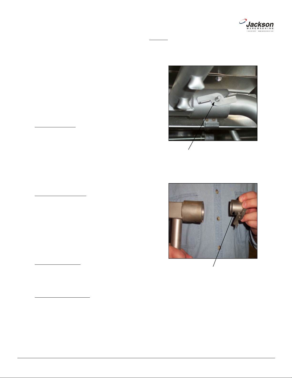
1. Remove the upper wash arm assembly by loosening the spin
-
2. Remove the end cap from the wash arm assembly and place in
assembly, set the assembly gently to the side. Go back inside the
unit to where the upper wash arm assembly secured in the unit and
turn the spin nut so that it is all the way down. This needs to be
done because in a further step, if the spin nut is out, it will get in
the way. Do not over-tighten the spin nut as it only needs to be out
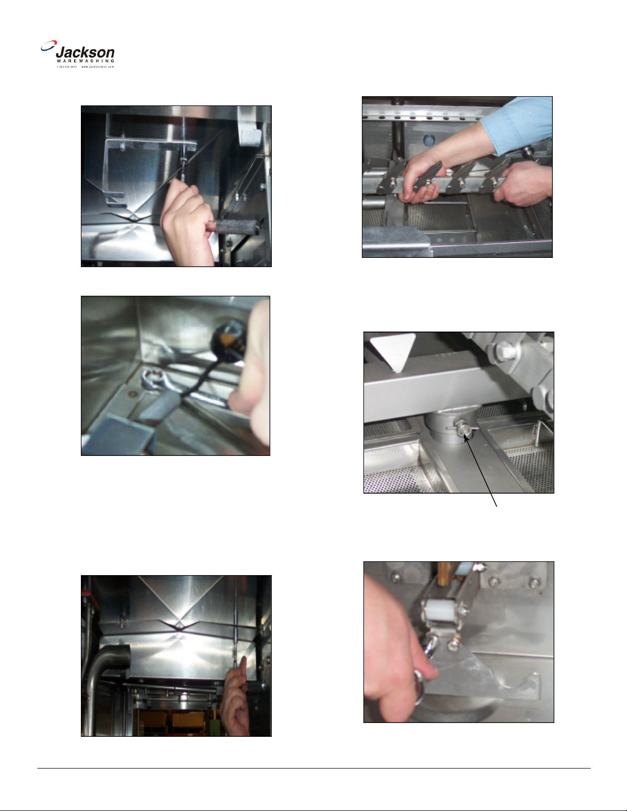
4. Remove the upper wash arm assembly bracket. This step may
require that you have help as the bolts for securing the bracket to
the top of the inner hood are the same bolts that hold the control
box to the hood top. Do not remove the bolts once the nuts are
-
ly back on the bolts. To hold the bolts (to keep them from spinning),
www.jacksonmsc.com
The Jackson model AJ-44 series dishmachine has the
ability to have its direction of travel changed from left to right, or
from right to left. Direction of travel is determined by which end the
rack of ware is put into the machine and which end the rack comes
out.
There may come times when it is necessary to change
the direction of travel after the unit is installed. The instructions provided here are for maintenance personnel only. Unauthorized persons should not attempt any of the steps contained in these
instructions.
Warning: many of the instructions and steps within
this document require the use of tools and may also require
that personnel change the wiring of the machine. Only authorized personnel should ever perform any maintenance evolution on the dishmachine!
PREPARATION
1. Power must be secured to the unit at the service breaker. Tag or lock out the service breaker to prevent accidental or
unauthorized energizing of the machine.
2. Disconnect incoming water at the water pressure regulator or Y-strainer.
3. Disconnect the service drain line from the drain plumbing of the dishmachine itself. Ensure that the unit is completely
drained before doing this.
4. Remove the locking screw from the control box.
5. Remove the front dress panel.
STEPS
nut. The spin nut has a stop so it will not come off. Once it is loos
ened, the wash arm assembly should slide off.
Spin nut
the opposite end, securing it snugly.
TOOLS REQUIRED
The following tools will be needed to perform this mainte-
nance evolution:
1. 5/16” nutdriver
2. 7/16” nutdriver
3. 7/16” combination wrench
4. 7/16” socket with drive ratchet and 4” extension
5. 12” pipe wrench
6. 10” adjustable wrench
7. Wire cutters
8. Phillipshead screwdriver
TIME REQUIRED
It is estimated that it will take (1) person three hours to
perform this task, not including all of the items indicated in the section entitled “PREPARATION”.
IMPORTANT NOTES
1. Do not lose hardware! Place hardware in a safe spot
away from the machine, ensuring that it does not fall loose into the
machine tub. Hardware that is drawing into the suction of the wash
pump will damage the equipment. If you do need more hardware,
contact Jackson to purchase new items.
2. Read these instructions thoroughly before attempting
this maintenance evolution. Become familiar with the parts and
what actions need to be taken. This will save time in the long run!
End cap
3. With the end cap securely in the opposite end of the wash arm
of the way, not secured.
taken off. Once the bracket is removed, place the nuts immediate
2
AJ-44 Conveyor Direction Change Instructions
Revision A (03/30/2005)
Page 3
7. Remove the lower wash arm assembly by turning the locking
8. Remove the lower wash arm support bracket. Place it to the side
www.jacksonmsc.com
a 7/16” combination wrench or 7/16” nutdriver will be required in
order to hold the bolt head inside the control box.
Removing bracket (bottom view)
6. Remove the pawl bar and set to the side.
Remove the pawl bar by grapsing firmly and
lifting up.
screw to unlatch it. The entire assembly should then lift out.
Removing bracket (control box view)
Remove the locknuts from the opposite bolts used to hold down the
control box (do not remove the bolts) and secure the bracket to
underside of the hood. The folded part of the bracket should be facing the rear of the machine. Immediately tighten down the locknuts.
5. Remove the splash shield, which is bolted to the underside of
the hood next to the wash manifold and turn it 180B.
Removing and turning splash shield
Locking screw
with its locknuts.
Removing the locknuts for the lower wash arm
support bracket.
AJ-44 Conveyor Direction Change Instructions
Revision A (03/30/2005)
3
Page 4

12. Remove the nuts from the rinse manifold mounting bracket
located on the underside of the hood. These nuts are mounted
13. The rinse manifold must be removed. This may prove difficult
while the rinse injector is still mounted. With great care, it is possi
-
ble to gently lift the rinse injector off of the hood to allow the rinse
manifold to be removed from the unit. Ensure that the gasket in the
underside of the hood stays with the rinse manifold as it must be
replaced when re-installing the manifold. If the gasket becomes
14. Remove the entire rinse tray assembly, including the pan and
the strainer within in. The assembly should lift right out. (See next
Note:
the brackets are mounted to the bolts that secure the tub
Once the locknuts are removed, pull the
locator brackets off and immiediately replace the locknuts back
onto the bolts. Failure to do so at a minimum may cause excessive
www.jacksonmsc.com
9. Remove the lower rinse arm support bracket, which is mounted
directly opposite of the lower wash arm support bracket.
directly to the rinse injector weldment on the hood top.
Removing the lower rinse arm support bracket
10. Remove the lower and upper rinse arms by unscrewing them
and then gently pulling them out.
Unscrewing and removing the lower rinse arm
11. Behind the rinse manifold, remove the nut on the bracket.
Removing the locknuts from the rinse mani -
fold mounting bracket
lost or torn, order a new one immediately.
Lifting the rinse injector to make room
Removing the bracket nut
page for photograph detailing this step)
15. Remove the front and rear rinse pan locator brackets.
weldment to the frame.
leaking of the tub once the unit is placed back in operation.
4
AJ-44 Conveyor Direction Change Instructions
Revision A (03/30/2005)
Page 5

so
that it is facing the opposite direction. This may require dismantling
the plumbing by removing the tee with the wash drain barb in it. Put
the plumbing back together, after ensuring that the rinse drain tee
has been rotated. Use thread tape to protect the threads while put
-
ting the plumbing back together. Ensure that the wash drain barb
18. On the underside of the tub, remove the rinse drain weldment
and the rinse drain plug. Switch their locations so that the rinse
19. Reconnect the rinse drain hose and the wash drain hose to the
20. On the opposite end from where they were removed, install the
Note: the
-
Install the brackets one at a time and ensure
21. Remove the hole cover weldment from the top of the hood. The
-
Lifting out the rinse tray assembly
www.jacksonmsc.com
17. The tee that the rinse drain nipple is in must be turned 180B
is in the exatc same position it was prior to this step.
drain weldment is in the spot that the rinse drain plug was in.
Removing a rinse tray guide bracket
16. On the drain plumbing, the rinse drain tube needs to be
removed from the plumbing, as well as the wash drain tube. Both
of these tubes are secured with hose clamps. Loosen the hose
clamps and pull the tubes off.
Loosening the rinse drain hose from the rinse
drain nipple
Removing the rinse drain weldment
Removing the rinse drain plug
drain plumbing.
front and rear rinse pan assembly locating brackets.
brackets are mounted to the bolts that secure the tub weld
ment to the frame.
that they are firmly tightened down once installed.
AJ-44 Conveyor Direction Change Instructions
Revision A (03/30/2005)
cover is located on the end of the hood opposite of the rinse injec
5
Page 6

28. Re-install the lower wash arm support bracket to the pawl bar
support on the end of the tub opposite from where it was removed.
29. Re-install the upper and lower rinse arms. Reinstall the lower
and
31. Re-install the pawl bar. Ensure that the pawl bar is placed so
that when racks are placed in the unit, the pawl bar dogs fold down.
32. Re-install the upper wash arm assembly. If you performed all of
the actions outlined in step 2, when you install it, it will be directly
33. Remove the heater box cover by unscrewing the four screws
www.jacksonmsc.com
tor weldment. Once removed, set to the side along with its gasket.
rinse arm support bracket.
30. Re-install the lower wash arm assembly, turning it 180B
locking it in place with the locking screw.
over the lower wash arm assembly.
Removing the hole cover weldment
22. Separate the rinse plumbing from the rest of the incoming
plumbing by loosening the union. Ensure that the gasket on the
bottom of the rinse injector stays with the assembly as you remove
it.
Loosening the union on the incoming plumbing
23. Remove the remaining half of the union from the incoming
plumbing.
holding it on.
1
Removing the heater box cover
2
3
24. Remove the incoming water pressure regulator from the incoming plumbing and replace with the union half that was removed in
step 23. Place the water pressure regulator on the end that the
union half was removed from.
25. Place the removed rinse plumbing assembly (with the gasket)
in the hole left open from when you removed the hole cover weld ment in step 21. Tighten the two halves of the union together.
26. Place the hole cover weldment (with its gasket) over the hole
from where the rinse plumbing assembly was originally installed.
Tighten down with the locknuts.
27. Re-install the rinse manifold (with its gasket) by connecting it to
the rinse injector weldment at its new location. Remove the locknut
from the stud for the bracket down near the rack rails and then
secure the bracket to the machine using the same lock nut.
Front of rack conveyor showing the conveyor
switches
6
AJ-44 Conveyor Direction Change Instructions
Revision A (03/30/2005)
Page 7

Conveyor Switch Chart:
1. Reconnect the incoming water and drain lines and then
restore power to the unit. Run the unit for at least 1/2 hour to
ensure there are no leaks. Test the unit with an empty rack to
ensure that it pulls the rack all of the way through the unit. If any
2. Replace the front dress panel once the unit is ready for
1. There is a possibility that you may be required to short
-
en or lengthen the conduit and wire lengths for the inlet solenoid
on the rinse plumbing once it is moved. This work should be per
-
formed by qualified technicians who will do the work according to
applicable local, state and national codes. Questions concerning
www.jacksonmsc.com
Unit
Direction
Left to Right Wash Switch #1 Wash Switch #2 Rinse Switch
Right to Left Rinse Switch Wash Switch #2
The chart above lists the conveyor switches and their functions,
depending on the direction fo travel for the machine. As you can
see, when you change the direction of the conveyor, you must also
alter the way the conveyor switches operate.
There is no need to remove the switches, only to change the wiring
inside the heater box.
Switch #1 Switch #2 Switch #3
Wash Switch
#1
Incoming plumbing assembly for a Left to Right machine
(note hole cover weldment in lower right corner)
Terminal board inside the heater box
34. Note: Before beginning any part of this maintenance evolution
that deals with the wiring of the machine, ensure that it is performed by qualified technicians only. Always refer to the machine
schematic, located inside the control box, for any questions.
Wash Switch #1 and the Rinse Switch need to have their wire positions changed on the terminal board pictured above. Locate the
gray/yellow wire for Wash Switch #1 (do not confuse it with the
gray/yellow wire for Wash Switch #2) and the orange/yellow wire
for the Rinse Switch. Exchange their positions on the terminal
board.
35. Verify that the plumbing has been reassembled correctly and
that the hole cover weldment has been replaced and none of the
gaskets are torn or pinched as this could lead to leaking when the
machine operates.
AJ-44 Conveyor Direction Change Instructions
Revision A (03/30/2005)
Incoming plumbing assembly for a Right to Left machine
(note hole cover weldment in upper left corner)
35. Re-install the heater box cover.
AFTER MAINTENANCE ACTIONS
problems arise you can contact Jackson Technical Service.
service again.
SPECIAL NOTES
this should be directed to Jackson Technical Service.
7
Page 8

www.jacksonmsc.com
2. Work performed on Jackson dishmachines by unauthorized or unqualified personnel may void the warranty. Before beginning this or any other maintenance evolution on a unit under warranty, you should contact a certified Jackson technician or Jackson
Technical Service. You can find a list of qualified service agencies
in the back of you unit’s installation manual.
SPECIAL PARTS
Gasket, Rinse Injector:
Order using part number 5330-111-42-81
CONTACT INFORMATION
Jackson MSC Inc. provides technical support for all of the
dishmachines detailed in this manual. We strongly recommend that
you refer to this manual before making a call to our technical sup port staff. Please have this manual with you when you call so that
our staff can refer you, if necessary, to the proper page. Technical
support is available from 8:00 a.m. to 5:00 p.m. (EST), Monday
through Friday. Technical support is not available on holidays.
Contact technical support toll free at 1-888-800-5672. Please
remember that technical support is available for service personnel
only.
8
AJ-44 Conveyor Direction Change Instructions
Revision A (03/30/2005)
 Loading...