

Page 1
AJ-44C Series Technical Manual 7610-001-76-22
Issued: 03-21-2006 Revised: N/A
SECTION 5: PARTS SECTION
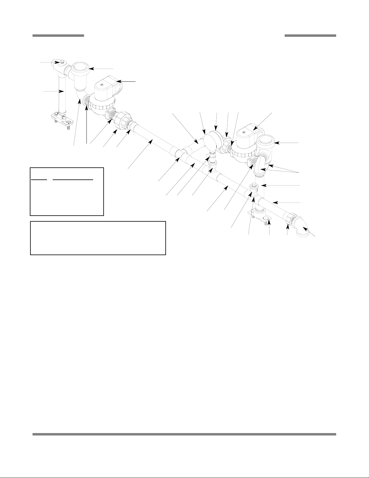
WASH/FILL PLUMBING ASSEMBLY (CGP MODELS)
83
1
5
2
3
3
4
19
6
6
7
8
9
18
6
18
5
21
15
20
10
14
11, 12
12, 13
8
22
17
16
11
47
ITEM QTY DESCRIPTION Mfg. No.
1 1 Rinse Injector Weldment Replacement Kit 06401-003-11-84
1 Gasket 05330-111-42-81
2 3 Plug, 1/8” NPT, Brass 04730-209-07-37
3 2 Vacuum Breaker, 3/4” NPT 04820-002-53-77
4 2 Valve, Solenoid, 3/4” NPT, 110 Volt 04810-100-53-00
5 3 Elbow, 3/4” Street Brass 04730-206-04-34
6 4 Nipple, Close, Brass, 3/4” NPT 04730-207-34-00
7 4 Union, 3/4”, Copper to Copper 04730-212-05-00
8 2 Adapter, 3/4” Fitting x Male 04730-401-11-01
9 1 Elbow, 90° 3/4” Copper to MSPS 04730-406-42-01
10 1 Tee, 3/4”, CU x CU x CU 04730-411-46-01
11 2 Tee, 3/4” x 3/4” x 1/2” 04730-411-03-01
12 2 Fitting, Adapter, 1/2” to 1/4” 04730-401-41-01
13 1 Plug, 1/4” NPT, Brass 04730-209-01-00
14 1 Test Cock, Valve, Ball, 1/4” NPT 04810-011-72-67
15 1 Gauge, Pressure, 0-100 PSI 06685-111-88-34
16 1 Nipple, Brass, 6” Long 05700-001-26-74
17 1 Fill Injector Replacement Kit 06401-003-09-93
1 Gasket 05330-111-42-81
18 1 Tube, Copper See Chart
19 1 Tube, Copper See Chart
20 1 Tube, Copper See Chart
21 1 Tube, Copper See Chart
22 1 Elbow, 3/4” NPT, 90° Brass 04730-206-13-00
Tube Length Chart
Item #
Length (Inches)
18 3/4” x 2-13/16”
19 3/4” x 3-7/16”
20 3/4” x 3”
21 3/4” x 2-5/8”
Replacement Kits Notes:
The rinse injector and fill injector replacement kits come
with the injector weldments, the gaskets and hardware
for mounting. In the case of Item (1) below, it also comes
with the required (3) brass plugs.
Page 2
AJ-44C Series Technical Manual 7610-001-76-22
Issued: 03-21-2006 Revised: N/A
SECTION 5: PARTS SECTION
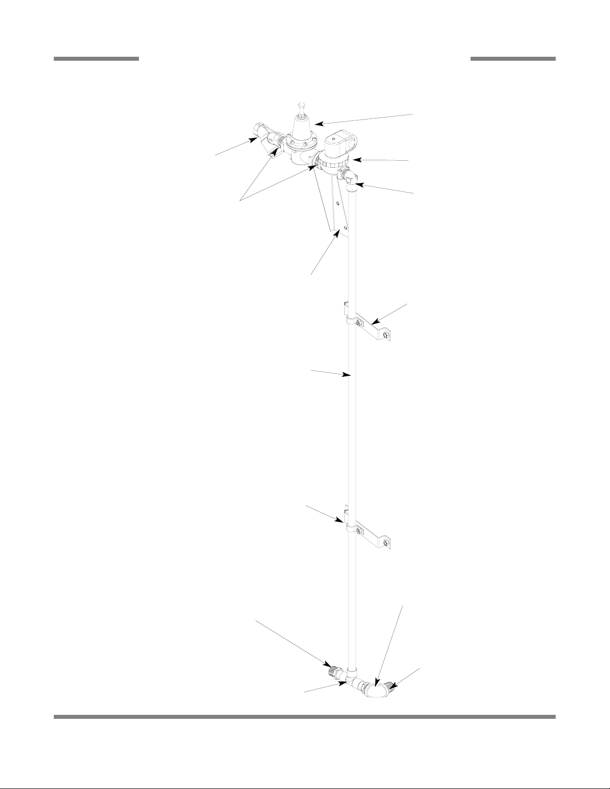
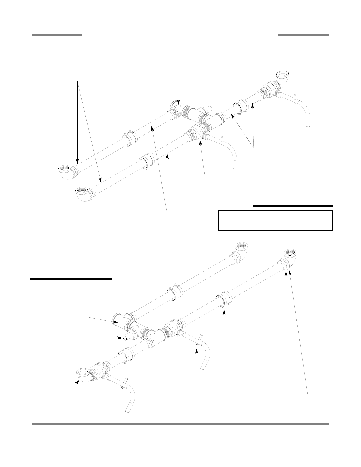
RINSE HEADER PLUMBING ASSEMBLY (CGP MODELS)
84
Copper Tube
3/4” x 56” Long
Incoming Plumbing Support Bracket
05700-002-50-70
Nipple, 3/4” Close Brass
04730-207-34-00
Solenoid Valve, 3/4” 110V
04810-100-53-00
Valve, 3/4” Pressure Reducing
04820-002-51-53
Y-Strainer, 3/4” Brass
04730-717-02-06
Inlet Plumbing Mounting Bracket
2 per
05700-002-51-41
Clamp, Pipe
2 per
05700-000-35-06
Elbow, 3/4” NPT 90° Brass
04730-206-13-00
Nipple, 3/4” Close Brass
04730-207-34-00
Adapter, 3/4”
04730-401-10-01
Tee, 3/4” x 3/4” x 3/4”
04730-411-46-01
Elbow, 3/4” Slip x 3/4” NPT
04730-406-42-01
Page 3
AJ-44C Series Technical Manual 7610-001-76-22
Issued: 03-21-2006 Revised: N/A
SECTION 5: PARTS SECTION
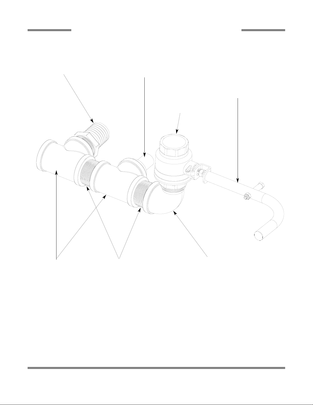
AJ-44 SERIES DRAIN PLUMBING ASSEMBLIES
85
AJ-44 Series Ball Valve Handle Assembly
06401-021-83-53
AJ-44CGP Ball Valve Handle Assembly
06401-021-84-74
Ball Valve, 1-1/2” NPT
04820-111-71-46
Elbow, 1-1/2” Brass 90° Street
04730-206-32-00
Nipple, 1-1/2” Brass, Close
04730-207-40-00
Tee, 1-1/2” Brass
04730-011-69-93
Nipple, Rinse Weldment
05700-021-84-61
Fitting, Barbed, 1-1/2” NPT x 1-1/2”
04730-011-69-92
Page 4
AJ-44C Series Technical Manual 7610-001-76-22
Issued: 03-21-2006 Revised: N/A
SECTION 5: PARTS SECTION
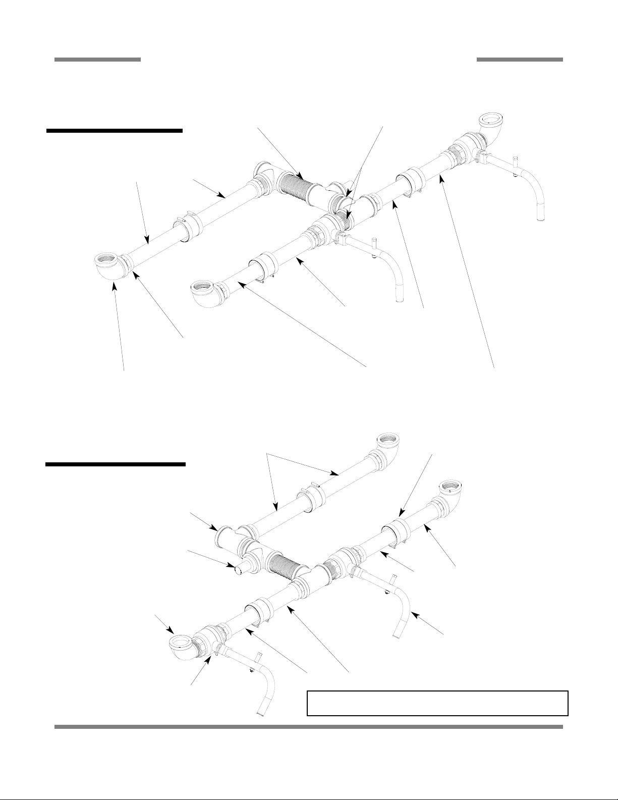
AJ-66 DRAIN PLUMBING ASSEMBLIES
86
Tube, Copper, 1-1/2” x 8-1/4” Long
Adapter, Male to Female, 1-1/2”
04730-401-25-01
Elbow, 1-1/2” FNPT, 90°, Brass
04730-011-73-77
Tube, Copper, 1-1/2” x 4-3/4” Long
Tube, Copper, 1-1/2” x 4-1/4” Long
Left to Right Plumbing
Assembly
Connector, No-Hub, 1-1/2”
04720-604-06-00
Valve, Ball, 1-1/2”
04820-111-71-46
Ball Valve Handle Assembly
06401-021-84-74
Nipple, Brass, Close, 1-1/2” NPT
04730-207-40-00
Nipple, Brass, Close, 3” NPT
04730-011-87-04
Tee, Brass, 1-1/2” x 1-1/2” x 1-1/2”
04730-011-69-93
Tube, Copper, 1-1/2” x 8-1/4” Long
Tube, Copper, 1-1/2” x 4-3/4” Long
Tube, Copper, 1-1/2” x 4-1/4” Long
Nipple, Rinse Weldment
05700-021-84-61
Elbow, Brass, Street, 1-1/2” NPT
04730-206-32-00
Right to Left Plumbing
Assembly
All parts are common to both assemblies.
Service Note: Copper tubing should be purchased locally and
cut to length (lengths provided in drawings).
Page 5
AJ-44C Series Technical Manual 7610-001-76-22
Issued: 03-21-2006 Revised: N/A
SECTION 5: PARTS SECTION
AJ-80 DRAIN PLUMBING ASSEMBLIES
87
Tube, Copper, 1-1/2” x 15-3/16” Long
Tube, Copper, 1-1/2” x 11-3/16” Long
Valve, Ball, 1-1/2”
04820-111-71-46
Tube, Copper, 1-1/2” x 4-15/16” Long
Left to Right Plumbing
Assembly
Adapter, Male to Female, 1-1/2”
04730-401-25-01
Elbow, 1-1/2” FNPT, 90°, Brass
04730-011-73-77
Connector, No-Hub, 1-1/2”
04720-604-06-00
Ball Valve Handle Assembly
06401-021-84-74
Nipple, Brass, Close, 1-1/2” NPT
04730-207-40-00
Tee, Brass, 1-1/2” x 1-1/2” x 1-1/2”
04730-011-69-93
Nipple, Rinse Weldment
05700-021-84-61
Elbow, Brass, Street, 1-1/2” NPT
04730-206-32-00
Right to Left Plumbing
Assembly
Assemblies are mirrored and all parts are common to both assemblies.
Service Note: Copper tubing should be purchased locally and cut to length (lengths provided in drawings).
Page 6
AJ-44C Series Technical Manual 7610-001-76-22
Issued: 03-21-2006 Revised: N/A
SECTION 5: PARTS SECTION
AJ-66CGP (LEFT TO RIGHT) DRAIN PLUMBING ASSEMBLY
88
ITEM QTY DESCRIPTION Mfg. No.
1 6 Adapter, Male to Female, 1-1/2” 04730-401-25-01
2 3 No-Hub Connector 04720-604-06-00
3 3 Tee, Brass, 1-1/2” FNPT 04730-011-69-93
4 2 Ball Valve, 1-1/2” FNPT 04820-011-71-46
* 2 Valve Handle Weldment Assembly (Not Shown) 06401-021-84-74
5 2 Nipple, Brass, Close, 1-1/2” NPT 04730-207-40-00
6 2 Elbow, Brass, 90°, 1-1/2” FNPT 04730-011-73-77
7 2 Tube, Copper, 1-1/2” x 1-3/4” Long See Service
Note
8 1 Rinse Nipple Weldment 05700-021-84-61
9 2 Tube, Copper, 1-1/2” x 3-1/2” Long See Service
Note
10 2 Tube, Copper, 1-1/2” x 7-1/2” Long See Service
Note
11 1 Nipple, Brass, 1-1/2” NPT x 3” Long 04730-011-87-04
Service Note: Copper tubing should be purchased locally and cut to length (lengths provided in parts list above).
6
6
5 2
2
1
3
4*
8
5
9
9
4*
3 1
2
1
1
10
11
137
10
13
3
5
7
Page 7
AJ-44C Series Technical Manual 7610-001-76-22
Issued: 03-21-2006 Revised: N/A
SECTION 5: PARTS SECTION
AJ-66CGP (RIGHT TO LEFT) DRAIN PLUMBING ASSEMBLY
89
ITEM QTY DESCRIPTION Mfg. No.
1 1 Elbow, 1-1/2” NPT, Brass, Street 04730-206-32-00
2 2 Valve, Ball, 1-1/2” FNPT 04820-011-71-46
3 6 Adapter, Male to Female, 1-1/2” 04730-401-25-01
4 4 Tube, Copper See Chart
5 3 Tee, Brass, 1-1/2” FNPT 04730-011-69-93
6 2 Nipple, Brass, 1-1/2” NPT, Close 04730-207-40-00
7 2 Tube, Copper See Chart
8 2 Tube, Copper See Chart
9 2 Elbow, Brass, 90°, 1-1/2” FNPT 04730-011-73-77
10 3 No-Hub Connector 04720-604-06-00
11 1 Nipple, Brass, 1-1/2” NPT x 3” Long 04730-011-87-04
12 1 Rinse Nipple Weldment 05700-021-84-61
13 1 Valve Handle Weldment Assembly 06401-021-84-74
14 1 Valve Handle Weldment Assembly 06401-002-57-83
3
10
4
5
8
7
9
2
5
6
6
3
12
3
10
3
11
4
3
1
9
5
4
4
10
32
14
13
Tube Length Chart
Item #
Length (Inches)
4 1-1/2” x 1-7/8”
7 1-1/2” x 5-3/16”
8 1-1/2” x 8-1/8”
Page 8
AJ-44C Series Technical Manual 7610-001-76-22
Issued: 03-21-2006 Revised: N/A
SECTION 5: PARTS SECTION
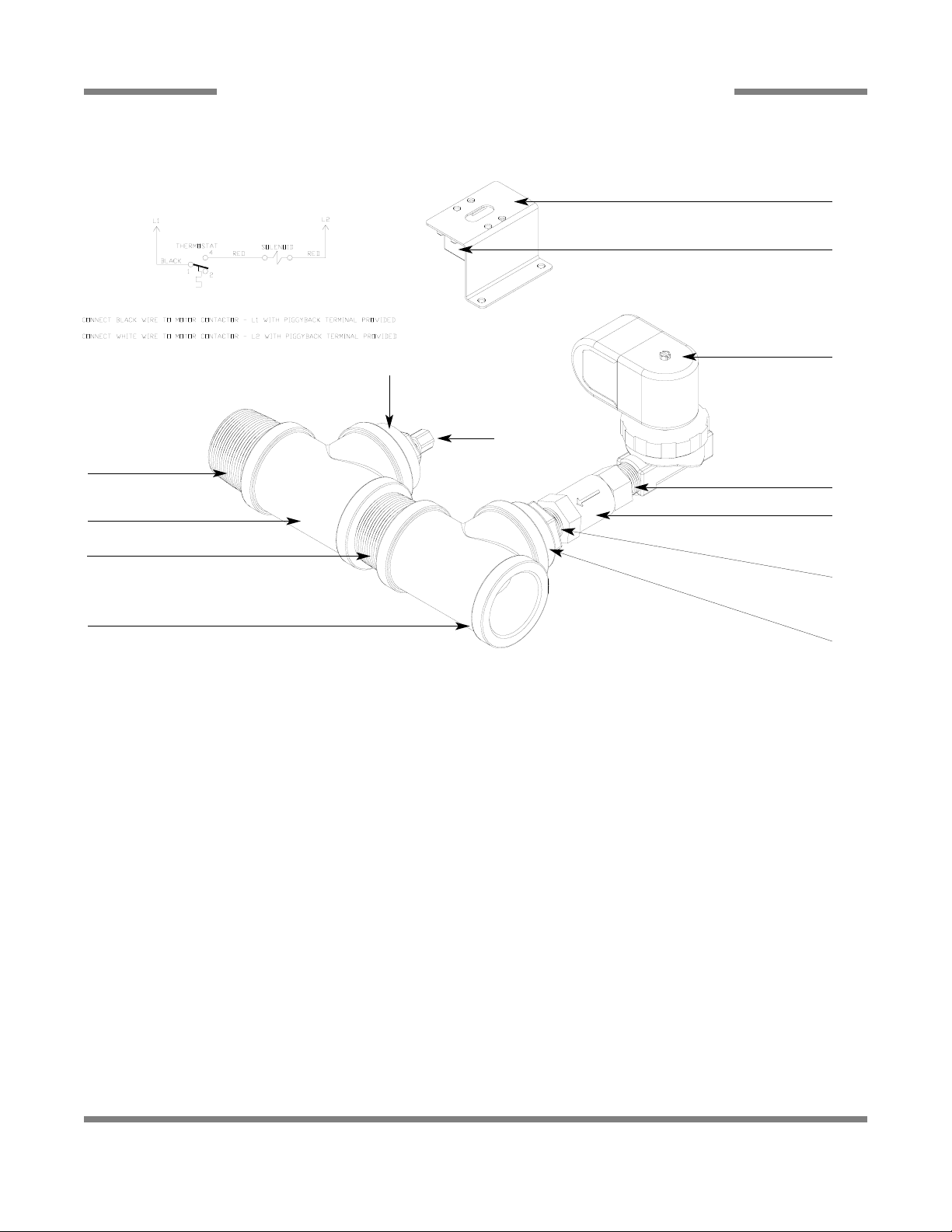
DRAIN QUENCH SYSTEM
90
ITEM QTY DESCRIPTION Mfg. No.
1 1 Thermostat 05930-121-67-72
2 1 Thermostat Bracket 05700-022-73-72
3 1 Solenoid Valve 04810-100-09-18
4 2 Nipple, Close, 1/2” NPT, Brass 04730-207-15-00
5 1 Valve, Check, 1/2” 04820-002-55-77
6 1 Reducer, 1-1/2” to 1/2” 04730-002-55-75
7 2 Tee, 1-1/2” x 1-1/2” x 1-1/2” 04730-011-69-93
8 2 Nipple, 1-1/2”, Close, Brass 04730-207-40-00
9 1 Reducer, 1-1/2” to 1/4” 04730-002-55-76
10 1 Modified Compression Fitting 05700-001-16-52
1 Complete Kit 06401-002-44-07
To Dishmachine Drain
To Drain
To Cold Water Supply
Schematic
1
2
3
4
5
4
6
7
8
7
8
9
10
From the existing drain, attach the two additional Tees (Item 7) using the 1-1/2” NPT Close Nipples (Item 8). Tighten the
Reducers (Items 6 & 9) into the Tees as shown above. Attach the Modified Compression Fitting (Item 10) into the 1-1/2” to 1/4”
Reducer (Item 9). Position the bulb of the thermostat (Item 1) so that it rests approximately 1/4” from the bottom of the Tee (Item
7). Tighten the Modified Compression Fitting (Item 10) as required.
Mount the Thermostat (Item 1) to the tub using the Thermostat Bracket (Item 2) and set it for 120
°
F - 140°F. Install the Solenoid
Valve (Item 3) to the second Tee (Item 7) and then attach to the incoming cold water line. Use pipe dope or thread tape as
required to prevent any leaks.
Page 9
AJ-44C Series Technical Manual 7610-001-76-22
Issued: 03-21-2006 Revised: N/A
SECTION 5: PARTS SECTION
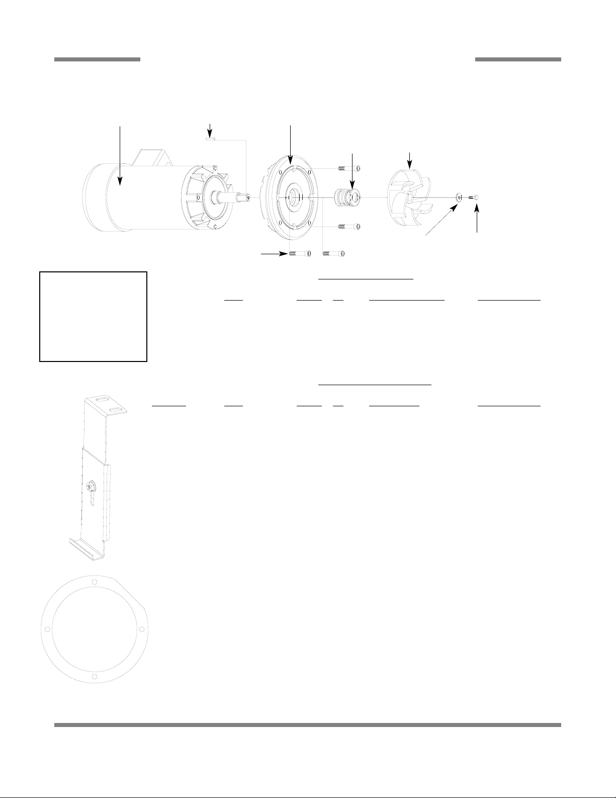
MOTOR ASSEMBLIES
91
WASH MOTOR CHART
Volts Phase Hz Motor Part Number Kit Part Number
200 - 440 3 50 06105-121-81-34 06401-003-09-96
208 - 230 1 60 06105-021-70-57 06401-003-09-97
200 - 230 3 60 06105-121-70-58 06401-003-09-98
380 3 60 06105-121-81-34 06401-003-09-96
460 3 60 06105-121-70-58 06401-003-09-98
600 3 60 06105-002-48-31 06401-003-09-99
PREW
ASH MOTOR CHART
Model(s) Volts Phase Hz Part Number Kit Part Number
AJ-66’s 208 3 50 06105-121-70-56 06401-003-10-38
220 3 50 06105-121-70-56 06401-003-10-38
230 3 50 06105-121-70-56 06401-003-10-38
380 3 50 06105-121-81-34 06401-003-10-39
415 3 50 06105-121-81-34 06401-003-10-39
440 3 50 06105-121-70-56 06401-003-10-38
208 1 60 06105-121-70-55 06401-003-10-40
230 1 60 06105-121-70-55 06401-003-10-40
200 3 60 06105-121-70-56 06401-003-10-38
220 3 60 06105-121-70-56 06401-003-10-38
230 3 60 06105-121-70-56 06401-003-10-38
380 3 60 06105-121-70-56 06401-003-10-38
460 3 60 06105-121-70-56 06401-003-10-38
600 3 60 06105-002-48-31 06401-003-10-41
AJ-80’s 208 3 50 06105-121-81-34 06401-003-10-39
220 3 50 06105-121-81-34 06401-003-10-39
230 3 50 06105-121-81-34 06401-003-10-39
380 3 50 06105-121-81-34 06401-003-10-39
415 3 50 06105-121-81-34 06401-003-10-39
440 3 50 06105-121-81-34 06401-003-10-39
208 1 60 06105-121-70-57 06401-003-10-42
230 1 60 06105-121-70-57 06401-003-10-42
200 3 60 06105-121-70-58 06401-003-10-43
220 3 60 06105-121-70-58 06401-003-10-43
230 3 60 06105-121-70-58 06401-003-10-43
380 3 60 06105-121-81-34 06401-003-10-39
460 3 60 06105-121-70-58 06401-003-10-43
600 3 60 06105-002-48-31 06401-003-10-41
See Motor
Chart Below
Key, 3/16” x 1” Long
Pump Plate
05700-021-71-83
Cap Screw, 3/8”-16 x 2”
05305-011-74-98
Wash Impeller Replacement Kit
06401-003-10-51
Prewash Impeller Replacment Kit
06401-003-10-55
Pump Seal
06401-003-06-73
Impellar Washer Bolt, 1/4”-20 x 3/4”
Motor Mounting Gasket
06401-003-06-75
Replacment Kit Notes:
The impeller replacement
kits come with the
impeller, washer, key and
bolt. The motor kits come
with everything detailed
above as well as two new
mounting gaskets.
Kit, Motor Brkt Replace
06401-021-73-42
Page 10
AJ-44C Series Technical Manual 7610-001-76-22
Issued: 03-21-2006 Revised: N/A
SECTION 5: PARTS SECTION
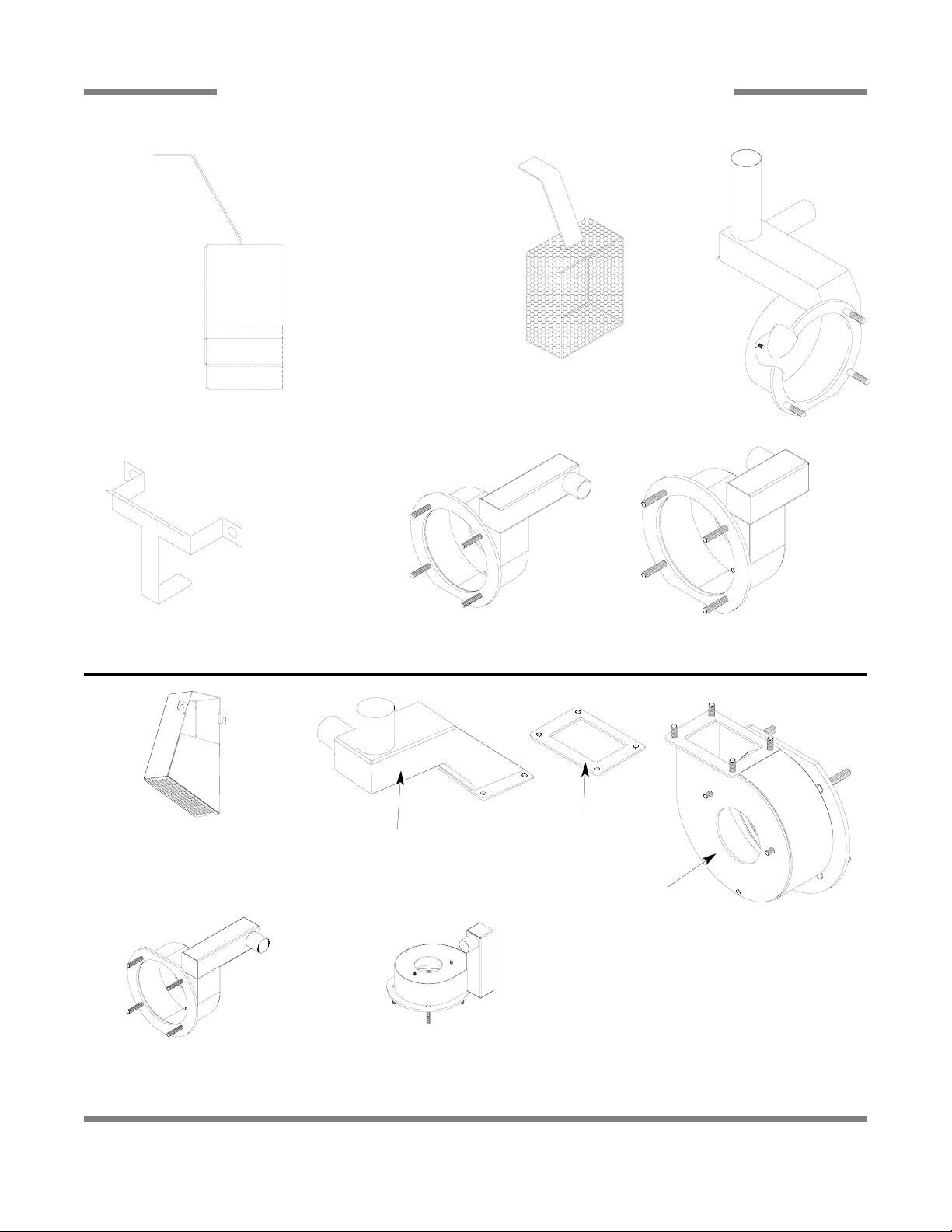
PREWASH & WASH PUMP WELDMENTS
92
Intake Suction Scoop Weldment
05700-021-87-60
Prewash Intake
Strainer Weldment
05700-021-74-96
Prewash Strainer
Bracket
05700-021-74-94
Prewash Pump Weldment
AJ-66/AJ-80 Right to Left models:
05700-002-11-96
Wash Pump
Weldment
05700-041-68-88
Prewash Pump Weldment
AJ-66/AJ-80 Left to Right models:
05700-002-10-62
Prewash Pump Weldment
AJ-66CGP Left to Right model
05700-002-43-56
Scoop, Intake Suction Wash
Weldment
05700-002-51-20
Pump Discharge
Weldment
05700-002-50-90
Gasket
05330-002-54-55
Wash Pump Weldment
05700-002-50-92
Prewash Pump Weldment
AJ-66CGP Right to Left model
05700-002-42-69
Page 11
AJ-44C Series Technical Manual 7610-001-76-22
Issued: 03-21-2006 Revised: N/A
SECTION 5: PARTS SECTION
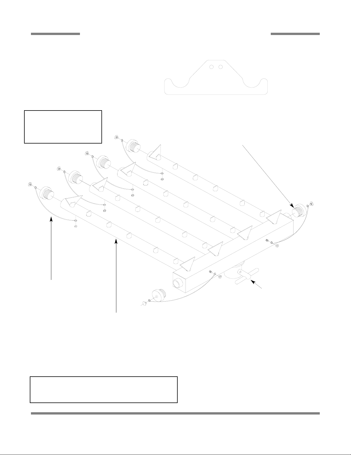
LOWER WASH ARM ASSEMBLY
93
End Cap Replacement Kit
06401-003-10-19
Lanyard
05340-011-72-46
Lower Wash Arm Manifold Weldment (50 Hz Models) 05700-002-24-87
Lower Wash Arm Manifold Weldment (60 Hz Models) 05700-031-67-29
Manifold Quick-Release Key
05700-011-94-45
Service Note:
When replacing the 10-32 screws in the End Caps, it is recommended that a thread locking fluid be used to ensure that the
screws do not back out during normal operation.
Lower Wash Arm Support Bracket
05700-011-71-20
Secured with Locknut, 1/4”-20 with Nylon Insert
05310-374-01-00
Replacement Kit Note:
The replacement kit for the end
cap includes the endcap, lanyard, mounting screw and the
locknut.
Complete Lower Wash Arm Assembly (50 Hz)
05700-002-24-86
Complete Lower Wash Arm Assembly (60 Hz)
05700-031-74-66
Page 12
AJ-44C Series Technical Manual 7610-001-76-22
Issued: 03-21-2006 Revised: N/A
SECTION 5: PARTS SECTION
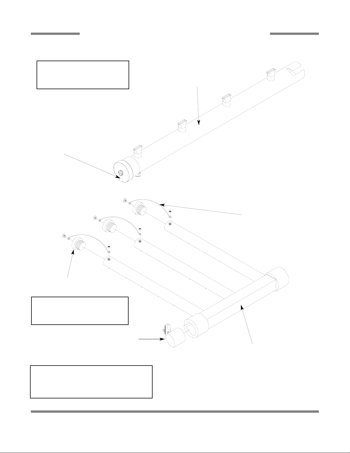
PREWASH ARM/UPPER WASH ARM ASSEMBLY
94
Lanyard
05340-011-72-46
End Cap Replacement Kit
06401-003-10-19
Upper Wash Arm Manifold Weldment
05700-031-67-34
Cap, Wash Tube
05700-021-69-68
Service Note:
When replacing the 10-32 screws in the End Caps, it
is recommended that a thread locking fluid be used to
ensure that the screws do not back out during normal
operation.
Replacement Kit Note:
The replacement kit for the end cap
includes the endcap, lanyard, mounting
screw and the locknut.
Upper Wash Manifold Support Bracket
05700-021-73-97
End Cap
Replacement Kit
06401-003-10-19
Replacement Kit Note:
The replacement kit for the end cap
includes the endcap, lanyard, mounting
screw and the locknut.
Prewash Tube
Weldment
05700-001-16-89
Complete Prewash Arm Assembly
05700-021-74-65
Complete Upper Arm Assembly
05700-031-74-99
Page 13
AJ-44C Series Technical Manual 7610-001-76-22
Issued: 03-21-2006 Revised: N/A
SECTION 5: PARTS SECTION
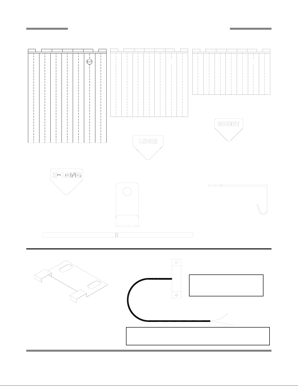
CURTAINS/TUB MAGNETS
95
Curtain, 21” Long x 20-1/2” Wide
08415-131-73-45
Curtain, 12” Long x 20-1/2” Wide
08415-131-73-44
Curtain Rod
05700-021-73-43
Long Curtain Decal
09905-011-73-84
Short Curtain Decal
09905-011-73-82
Curtain, 24 1/2” Long x 20-1/2” Wide
CGP MODELS ONLY
08415-002-47-37
Extra Long Curtain Decal
CGP MODELS ONLY
09905-002-52-69
Middle Curtain Hook
05700-011-72-65
Curtain Hook
05700-011-83-54
Limit Switch Bracket
05700-021-71-18
Conveyor Switch Replacement Kit
06401-003-11-79
Replacement Kit Note:
The conveyor switch replacement kit
comes with the switch, a terminal and
a wire nut.
Service Note:
The cord for the conveyor switch needs to be cut to length in the field
and have the pink terminal applied there.
Page 14
AJ-44C Series Technical Manual 7610-001-76-22
Issued: 03-21-2006 Revised: N/A
SECTION 5: PARTS SECTION
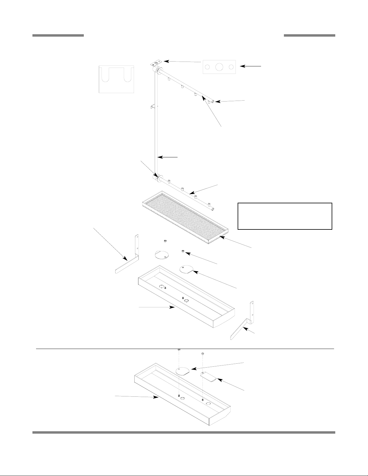
FINAL RINSE ASSEMBLY
96
Final Rinse Manifold Weldment
05700-021-74-88
Upper Rinse Arm Replacement Kit
06401-003-10-08
Lower Rinse Arm Replacement Kit
06401-003-10-09
Rinse Pan Strainer Weldment
05700-041-85-09
Rinse Drain Control Plate
05700-011-68-70
Rinse Drain Control Plate
05700-011-68-70
Rinse Drain Overflow Plate
05700-002-53-62
Left Rinse Pan Locator Bracket
05700-021-92-38
Right Rinse Pan Locator Bracket
05700-021-92-37
Rinse Tray Weldment
(All models except CGP)
05700-031-66-75
Rinse Tray Weldment
(CGP models only)
05700-031-66-75
Optional Parts for CGP
Models
Locknut, 1/4”-20 with Nylon Insert
05310-374-01-00
End plugs can be ordered using
part number 04730-209-07-37.
O-Ring
05330-011-74-55
Retaining Ring (Not Shown)
05340-112-01-11
Gasket
05330-111-42-81
Rinse Arm
Support Bracket
05700-011-71-19
Replacement Kit Note:
The replacement kits for the rinse
arms have the rinse arms, end caps, orings and the retaining rings.
Page 15

AJ-44C Series Technical Manual 7610-001-76-22
Issued: 03-21-2006 Revised: N/A
SECTION 5: PARTS SECTION
DRIVE ASSEMBLY
97
10
2
3
4
11
12
13
18
17
14
15
16
5
6
7
8
9
1
See Detail A
Page 16
SECTION 5: PARTS SECTION
DRIVE ASSEMBLY (CONTINUED)
Replacement Kit with Expansion Legs/Adjuster Crank 06401-011-94-54
17 1 Drive Motor Replacement Kits
1 Drive Motor (208-230 Volt, 60 Hz, Single Phase Models) 06401-003-08-42
Drive Motor (208-230 Volt, 60 Hz, Three Phase Models) 06401-003-08-40
Drive Motor (600 Volt, 60 Hz, Three Phase Models) 06401-003-08-43
.oN .gfMNOITPIRCSEDYTQMETI
44-76-120-00750tnemdleW doR dna etalP evirD11
08-68-120-10460sgeL noisnapxE htiw tiK tnemecalpeR
59-96-120-00750ylbmessA knarC retsujdA12
84-80-300-10460tiK tnemecalpeR tnemdleW ekoY hctokS13
09515-003-58-12tnemdleW geL noisnapxE & gnilpuoC24
37-78-120-51590gnitsaC egakniL evirD raB lwaP15
85-76-110-00750etalP recapS16
05-80-300-10460tiK tnemcalpeR kcolB wolliP27
81-98-110-00750ralloC tfahS28
93-76-120-00750tekcoS evirD19
24-76-120-00750etalP evirD101
78-17-120-02130kcolB wolliP211
15-38-110-51350gnirpS evirD121
81-98-110-00750ralloC tfahS231
65-37-130-00750tekcarB gnitnuoM rotoM evirD141
09-17-110-51350gnirpS retsujdA151
82-27-120-00750tnemdleW eldnaH gnitsujdA161
14-80-300-10460)sledoM zH 05( rotoM evirD
88-17-110-50160evirD raeG181
18-17-110-02130gniraeB relloR191
79-76-110-00750buH evirD102
19
20
Detail A
Front Drive Motor Cover
Replacement Kit
06401-003-11-64
Replacement Kits Notes:
The replacement kits for the drive motor covers come
with the weldments and the mounting hardware.
AJ-44C Series Technical Manual 7610-001-76-22
Issued: 03-21-2006 Revised: 10-09-09
98
Rear Drive Motor Cover
Replacment Kit
06401-003-10-18
Page 17
AJ-44C Series Technical Manual 7610-001-76-22
Issued: 03-21-2006 Revised: N/A
SECTION 5: PARTS SECTION
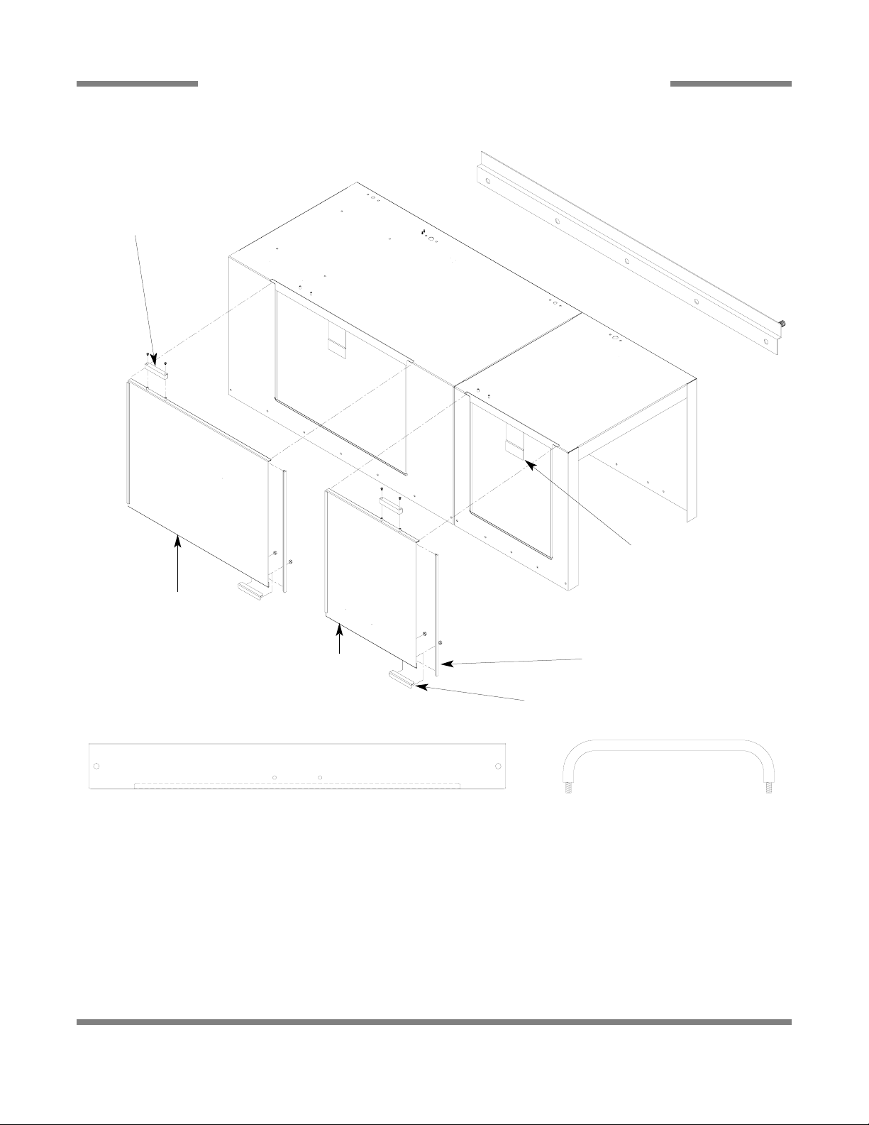
DOOR ASSEMBLIES
99
ITEM QTY DESCRIPTION Mfg. No.
1 1 Wash Door Assembly 05700-002-43-29
2 1 Prewash Door Weldment (Left to Right Model) 05700-002-52-50
2 1 Prewash Door Weldment (Right to Left Model) 05700-002-49-60
Door Stiffener (Not Shown) 05700-031-83-43
Door Catch Weldment
05700-031-84-80
2
Door Stop
05700-002-05-46
Door Glide
05700-111-70-92
1
Door Switch Magnet
Replacement Kit
06401-003-10-34
Wash Door Handle Weldment
05700-011-82-63
Prewash Door Handle Weldment
05700-011-80-45
Wash Door Hood Support: 05700-031-84-13
Prewash Door Hood Support: 05700-031-84-14
Left Door Guide Weldment
05700-002-32-51
Right Door Guide Weldment
05700-031-76-44
Page 18
AJ-44C Series Technical Manual 7610-001-76-22
Issued: 03-21-2006 Revised: N/A
SECTION 5: PARTS SECTION
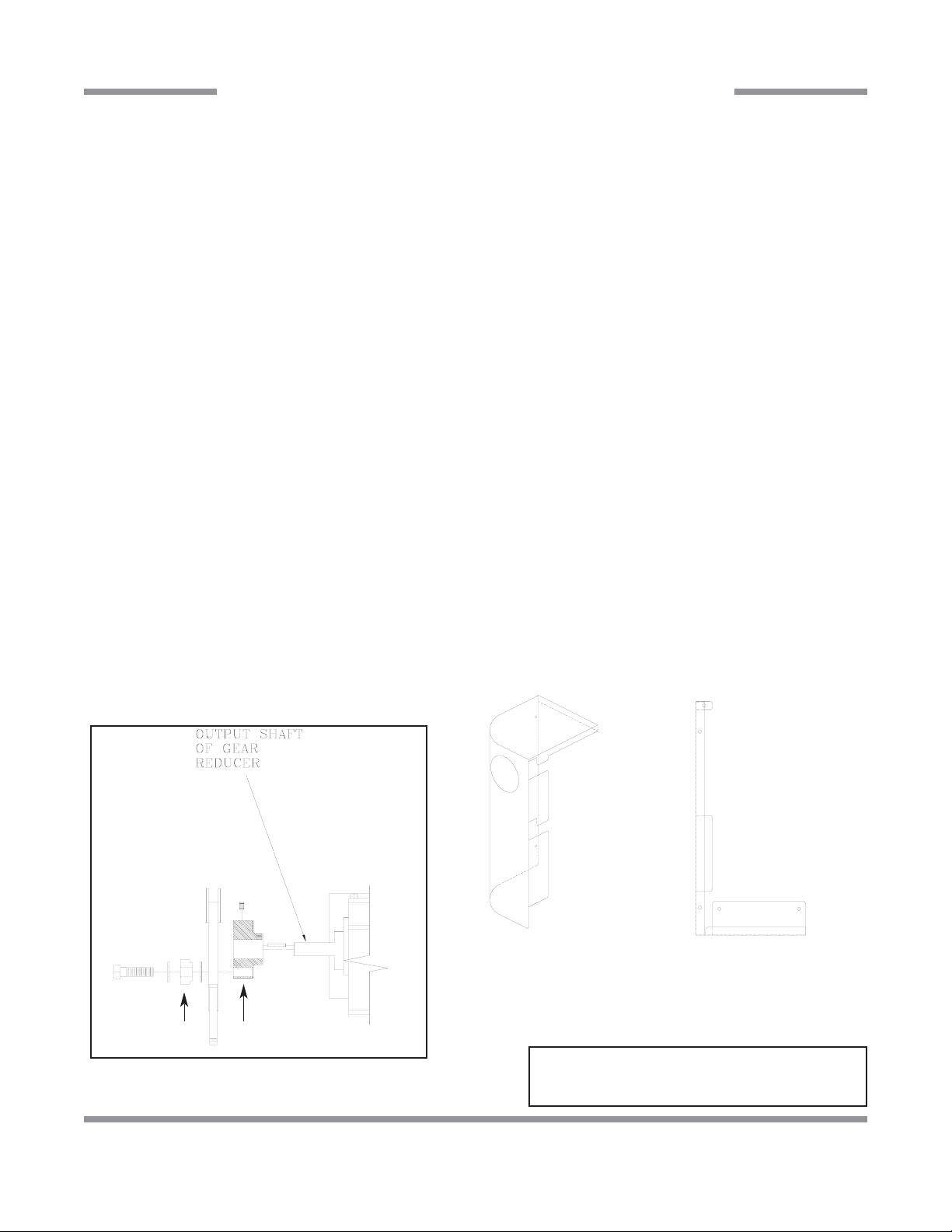
PAWL BAR MISCELLANEOUS COMPONENTS
100
Pawl Bar Gutter Weldment Replacement Kit
06401-003-09-95
Bottom Guide Block
Top Guide Block
Pawl Bar Gutter Gasket
05330-011-68-55
Replacement Kits Notes:
The pawl bar gutter weldment
replacement kit contains the weldment, a gasket and the mounting
hardware. The guide block kit contains both blocks and a gasket.
Service Note: It is highly recommended that when
changing out one guide block, that the other be changed
out as well, along with the gasket.
Guide Block Replacment Kit
06401-003-10-15
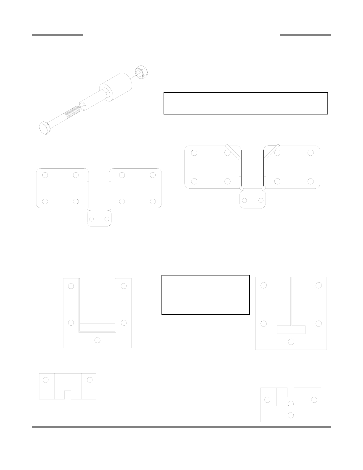
Pawl Bar Roller Replacement Kit
06401-003-11-80
Replacement Kit Notes:
The replacement kit for the pawl bar roller comes with the roller, roller
shaft, hardware and locknut as shown.
Pawl Bar Bracket (with studs) Weldment
05700-031-84-68
Pawl Bar Bracket (without tabs) Weldment
05700-031-92-36
Page 19
AJ-44C Series Technical Manual 7610-001-76-22
Issued: 03-21-2006 Revised: N/A
SECTION 5: PARTS SECTION
AJ-44 & AJ-66 PAWL BAR ASSEMBLIES
101
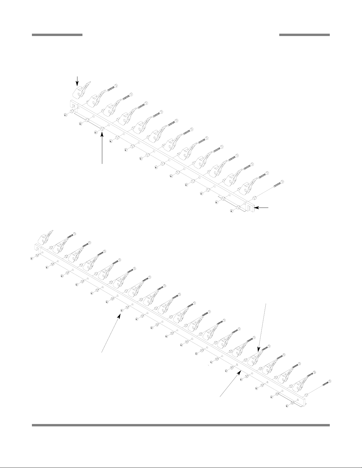
Pawl Bar Dog Casting
12 per
05700-021-69-00
AJ-44 Complete Assembly with Hardware
06401-131-81-00
AJ-44 Prison Assembly with Hardware
06401-231-81-00
Pawl Bar Spacer
24 per
05700-011-71-45
Pawl Bar Weldment
05700-031-72-77
AJ-66 Complete Assembly with Hardware
06401-141-74-64
AJ-66 Prison Assembly with Hardware
06401-241-74-64
Pawl Bar Spacer
36 per
05700-011-71-45
Pawl bar Weldment
05700-031-72-78
Pawl Bar Dog Casting
18 per
05700-021-69-00
Page 20

AJ-44C Series Technical Manual 7610-001-76-22
Issued: 03-21-2006 Revised: N/A
SECTION 5: PARTS SECTION
AJ-80 PAWL BAR ASSEMBLIES
102
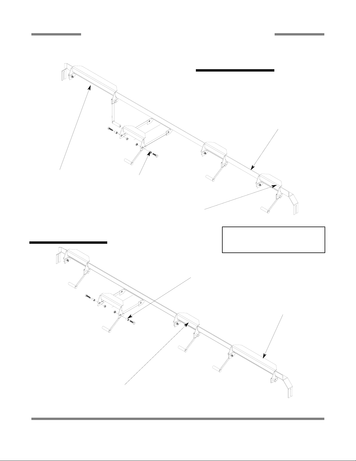
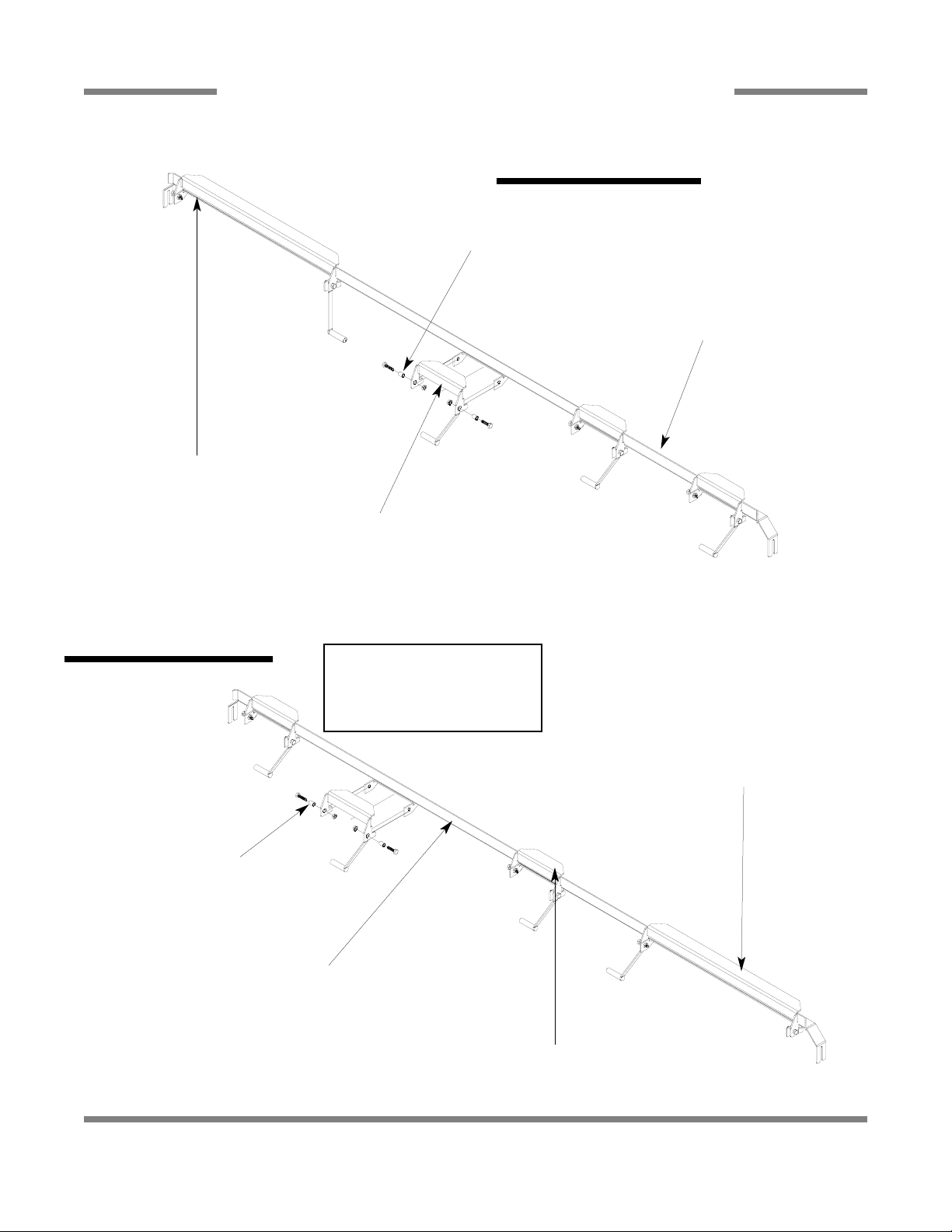
Bolt, 3/8”-16 x 1-3/4” Long
05306-011-36-94
Pawl Bar Spacer
05700-011-71-45
Pawl Bar Dog Casting
05700-021-69-00
Pawl Bar Weldment
05700-031-74-19
All associated hardware, spacers and castings may be
ordered using the part numbers indicated in the above
assembly.
Pawl Bar Weldment
05700-041-82-01
Both assemblies contain 40 pawl bar dog castings. Please
note the direction of installation as indicated on the above
drawings. When replacing pawl bar dog castings, ensure to
re-install in the appropriate direction. If you do not, then the
rack will not be pulled through the machine during operation.
AJ-80 Complete L-R Assembly
06401-141-81-06
AJ-80 Complete R-L Assembly
06401-241-81-06
AJ-80 Prison Assembly
06401-341-81-06
Page 21

AJ-44C Series Technical Manual 7610-001-76-22
Issued: 03-21-2006 Revised: N/A
SECTION 5: PARTS SECTION
AJ-44 RACK RAIL ASSEMBLY
103
Spacer
6 per
05700-011-71-44
Actuator Switch Replacement Kit
06401-003-10-14
Rack Rail Weldment
05700-031-67-59
Opposite Rack Rail
05700-031-69-48
Replacement Kit Note:
The replacement kit for the actuator
switch comes with the switch, two spacers and the mounting hardware.
Page 22
AJ-44C Series Technical Manual 7610-001-76-22
Issued: 03-21-2006 Revised: N/A
SECTION 5: PARTS SECTION
AJ-66 RACK RAIL ASSEMBLIES
104
Rack Rail Weldment
05700-031-76-27
Opposite Rack Rail
05700-041-71-37
Actuator Switch Replacement
Kit
06401-003-10-99
Rack Guide Spacer
8 per
05700-011-71-44
Actuator Switch Replacement Kit
06401-003-10-14
Left to Right Assembly
Right to Left Assembly
Rack Rail Weldment
05700-031-76-28
Actuator Switch Replacement
Kit
06401-003-10-86
Opposite Rack Rail
05700-041-69-54
Rack Guide Spacer
8 per
05700-011-71-44
Actuator Switch Replacement Kit
06401-003-10-14
Replacement Kit Notes:
The replacement kits for the actuator
switches come with the switch, two spacers
and the mounting hardware.
Page 23
AJ-44C Series Technical Manual 7610-001-76-22
Issued: 03-21-2006 Revised: N/A
SECTION 5: PARTS SECTION
AJ-80 RACK RAIL ASSEMBLIES
105
Rack Guide Weldment (Left to Right)
05700-031-81-53
Opposite Rail
05700-041-74-13
Actuator Switch Replacement Kit
06401-003-10-14
Left to Right Assembly
Actuator Switch Replacment Kit
06401-003-10-83
Rack Guide Spacer
05700-011-71-44
Right to Left Assembly
Actuator Switch Replacement Kit
06401-003-10-85
Actuator Switch Replacment Kit
06401-003-10-14
Rack Guide Weldment (Right to Left)
05700-031-81-54
Opposite Rail
05700-041-74-14
Replacement Kit Notes:
The replacement kits for the actuator switches come with the
switch, two spacers and the
mounting hardware.
Rack Guide Spacer
05700-011-71-44
Page 24

AJ-44C Series Technical Manual 7610-001-76-22
Issued: 03-21-2006 Revised: N/A
SECTION 5: PARTS SECTION
MISCELLANEOUS PARTS AND WELDMENTS
106
Run Off Sheet Weldment
05700-021-71-39
Plate, Right Water
Directional
05700-021-79-23
Plate, Left Water
Directional
05700-021-79-27
Splash Shield Weldment
05700-031-85-16
Hole Direction Plate Replacment Kit
06401-003-10-00
Replacment Kit Note:
The kit for the hole direction plate comes
with the plate, a new gasket and the
mounting hardware.
Pipe Clamp
05700-000-35-05
Rinse Drain Plate Replacment
Kit
(CGP Models Only)
06401-003-10-07
Rinse Drain Plug Replacement Kit
06401-003-10-06
Rinse Drain Weldment Replacement Kit
06401-003-10-05
Rinse Drain Plate Gasket
05330-011-72-27
Replacement Kits Notes:
The kits for the drain weldments and
drain plugs come with the
weldments/parts, a new gasket and the
mounting hardware.
Page 25

AJ-44C Series Technical Manual 7610-001-76-22
Issued: 03-21-2006 Revised: N/A
SECTION 5: PARTS SECTION
MANIFOLDS/STRAINER SUPPORT WELDMENTS
107
Prewash Manifold Weldment
AJ-66 Models Only
05700-031-69-70
Prewash Manifold Weldment
AJ-80 Models Only
05700-002-24-94
Prewash Manifold Weldment
(CGP Models Only)
05700-002-59-51
Wash Manifold Weldment
05700-031-71-13
Wash Manifold Weldment
(CGP Models Only)
05700-002-51-14
Shoulder Bolt Wingnut Weldment
05700-002-46-02
Wash Fill Tube Weldment
05700-021-71-21
Prewash Fill Tube Weldment
(AJ-66 & AJ-80 Models Only)
05700-021-74-76
Vellumoid Gasket
05330-111-42-81
Wash Strainer Separator Weldment
05700-031-84-38
Page 26

AJ-44C Series Technical Manual 7610-001-76-22
Issued: 03-21-2006 Revised: N/A
SECTION 5: PARTS SECTION
STRAINERS
108
Back Strainer Weldment
05700-021-85-11
Drain Guard
Strainer Weldment
05700-002-09-15
Front Strainer Weldment
05700-021-85-10
Screen Strainer
with Handle Weldment
05700-002-09-04
Overflow Strainer Support
05700-001-96-48
Tub Strainer Weldment (CGP Models)
05700-002-03-21
Wash Intake Strainer Weldment (CGP Models)
05700-002-51-52
Page 27

AJ-44C Series Technical Manual 7610-001-76-22
Issued: 03-21-2006 Revised: N/A
SECTION 5: PARTS SECTION
FLOAT SWITCH COMPONENTS/SCRAP BASKETS
109
Float Switch Support Bracket
Replacement Kit
06401-003-11-77
Float Switch Cover
05700-021-75-71
Scrap Basket Lid
Weldment
05700-002-56-55
Scrap Basket Assembly
06401-011-87-78
Wash Tank Float Switch Replacment Kit
06401-003-11-75
Prewash Tank Float Switch Replacment Kit
06401-003-11-76
Replacment Kit Note:
The float switch replacement kits contain the float switch with
associated terminals, the flat washer and the nut.
Service Agent Note:
Remember than when reinstalling the float switch that the flat
washer goes inside against the tub wall while the nut is on the
outside of the tub.
Replacment Kit Note:
The float switch support bracket replacement kit contains the bracket and associated hardware for mounting.
Page 28

AJ-44C Series Technical Manual 7610-001-76-22
Issued: 03-21-2006 Revised: N/A
SECTION 5: PARTS SECTION
VENT COWL ASSEMBLY/VENT SCOOP OPTION
110
Vent Cowl Cover Replacement Kit
06401-003-10-16
Gasket, Top Vent Cowl
05330-031-83-47
Vent Cowl Replacement Kit
06401-003-11-62
Gasket, Side Vent Cowl
2 per assembly
05330-031-83-48
VENT SCOOP OPTION
Replacement Kit Note:
The kit for the vent cowl comes with the vent
cowl weldment, new gaskets and the locknuts needed to mount it.
Vent Scoop Assembly
05700-002-04-08
Page 29

AJ-44C Series Technical Manual 7610-001-76-22
Issued: 03-21-2006 Revised: 09-29-2007
SECTION 5: PARTS SECTION
EXHAUST FAN CONTROL/TABLE LIMIT SWITCH
111
Delay Timer
05945-011-65-44
2” Din Rail
05700-002-36-09
Decal, Fan Load
09905-003-32-20
Kit, Exhaust Fan - Electric & Steam Models
05700-031-90-53
Kit, Exhaust Fan - Gas Models
05700-003-14-59
Terminal Board
05940-011-84-41
Limit Switch
05930-002-62-81
Striker Plate Limit Switch Assembly
05700-002-62-94
FAN LOAD ON TIMER OUTPUT
5A, 1/4HP, 240 V AC MAX
Page 30

AJ-44C Series Technical Manual 7610-001-76-22
Issued: 03-21-2006 Revised: N/A
SECTION 5: PARTS SECTION
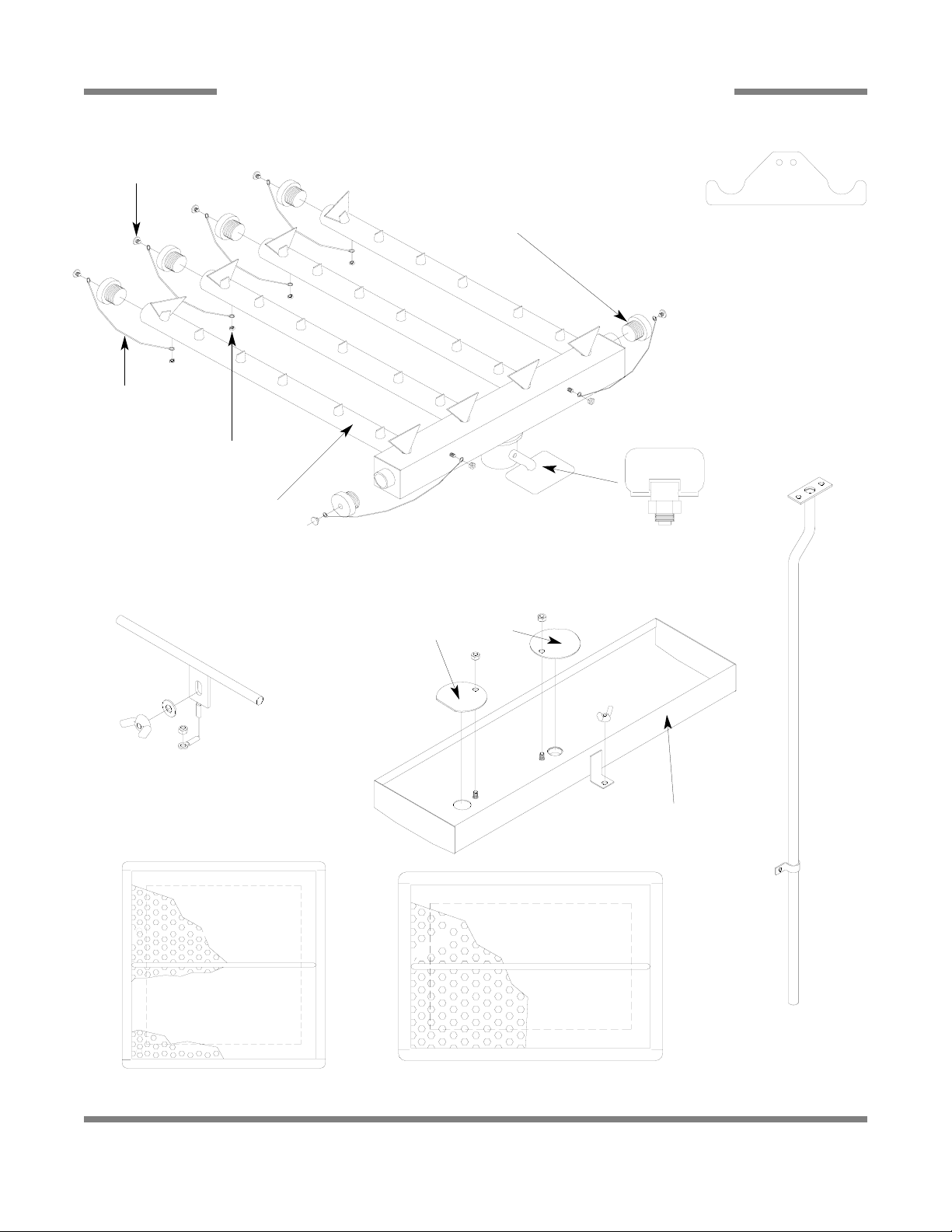
SIDE LOADER TRACK ASSEMBLY/LEG REPLACEMENTS/STRAINER
112
ITEM QTY DESCRIPTION Mfg. No.
1 1 Track Weldment (Left to Right) 24” 05700-031-78-98
1 Track Weldment (Right to Left) 24” 05700-031-95-20
1 Track Weldment (Left to Right) 30” 05700-003-04-57
1 Track Weldment (Right to Left) 30” 05700-003-04-58
2 1 Actuator Switch Replacement Kit 06401-003-10-64
3 2 Spacer 05700-011-71-44
4 1 Leg Socket Replacement Kit 06401-003-09-79
5 1 Leg Support Replacement Kit 06401-003-09-80
6 1 Bullet Foot 05340-108-01-03
1
2
3
Side loader track assembly
(left to right model shown).
Replacement Kits Notes:
The actuator switch replacement kit comes with the
actuator weldment, mounting hardware and (2)
spacers.
The leg socket replacement kit has the leg socket,
mounting hardware and set screw.
The leg support replacement kit has the leg and the
bullet foot included.
4
5
6
Front Strainer Weldment
05700-021-85-10
Page 31

AJ-44C Series Technical Manual 7610-001-76-22
Issued: 03-21-2006 Revised: N/A
SECTION 5: PARTS SECTION
SIDE LOADER PAWL BAR ASSEMBLIES/PAWL BAR BRACKET/MAGNET
113
Pawl Dog Wing Weldment
05700-021-86-79
Pawl Bar Spacer
05700-011-71-45
Drive Linkage Replacment Kit (L-R)
06401-003-11-59
Drive Linkage Replacement (R-L)
06401-003-11-60
Kit, Pawl Bar Replacement: 06401-131-86-90
Kit, 30” Pawl Bar Replacement: 06401-231-86-90
Replacement Kit Note:
The kits for the pawl bars come with the bar
weldment, (3) dogs and the hardware.
Replacement Kit Note:
The replacement kits for the drive linkages come also
with the hardware for mounting them to the pawl bars.
Pawl Bar Roller Bracket
05700-031-77-94
Replacement Kit Note:
The conveyor switch replacement
kit comes with the switch, a terminal and a wire nut.
Service Note:
The cord for the conveyor switch needs to
be cut to length in the field and have the
pink terminal applied there.
See page entitled “Pawl Bar
Miscellaneous Components”
for other parts used on the
Side Loader.
Page 32

AJ-44C Series Technical Manual 7610-001-76-22
Issued: 03-21-2006 Revised: N/A
SECTION 5: PARTS SECTION
SIDE LOADER VENT COWL OPTION
114
VENT SCOOP OPTION
Vent Scoop Assembly
05700-002-04-08
STANDARD ASSEMBLY
Vent Cowl Cover Replacement Kit
06401-003-10-16
Vent Cowl Replacement Kit (Left to Right)
06401-003-11-81
Vent Cowl Replacement Kit (Right to Left)
06401-003-11-83
Replacement Kit Note:
The replacement kit(s) for the vent cowls come with the
cowls, the gaskets and mounting hardware.
Replacement Kit Note:
The cover kit contains the
cover and the hardware for
mounting it.
Vent Cowl Gasket, Top: 05330-031-83-47
Vent Cowl Gasket, Sides: 05330-031-83-48
Service Note:
One of the side
gaskets that come
in the kit will need
to be cut to length
in order to fit properly on the unit
when replaced.
Vent Cowl Assembly for
Hooded Side Loader Option
05700-003-15-66
Page 33
AJ-44C Series Technical Manual 7610-001-76-22
Issued: 03-21-2006 Revised: N/A
SECTION 5: PARTS SECTION
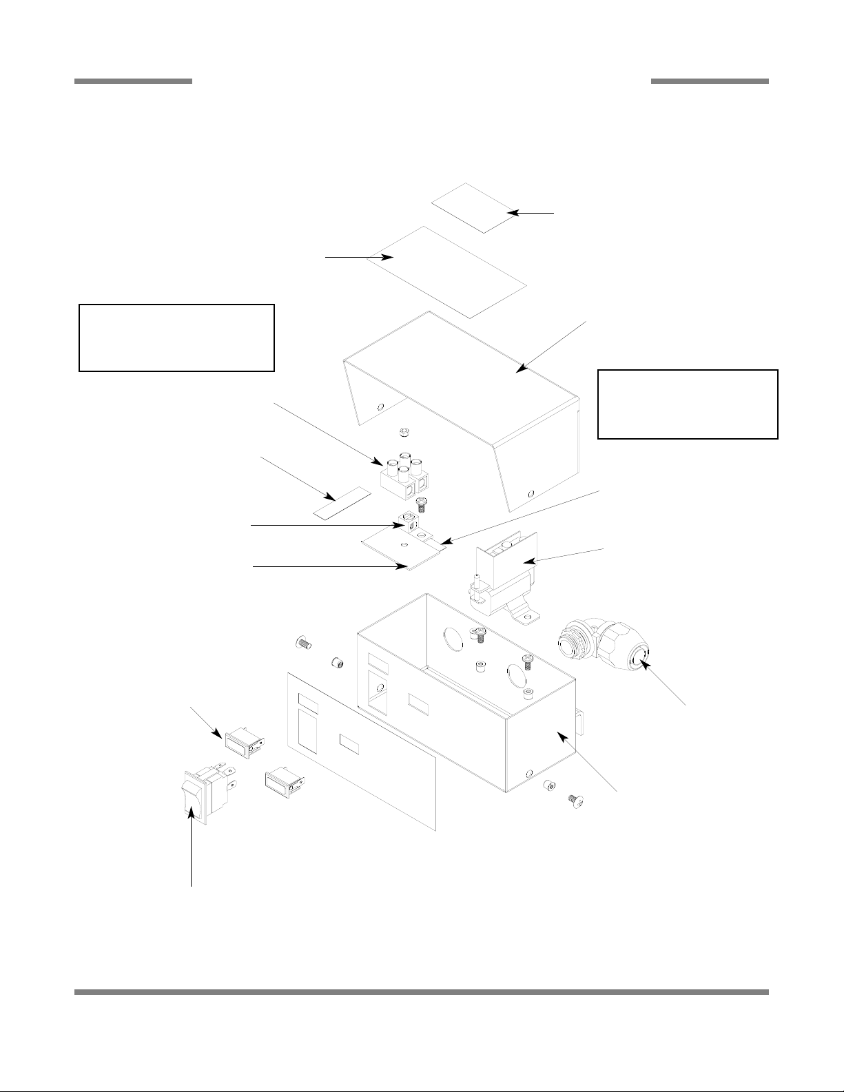
D226 STEAM BOOSTER CONTROL BOX ASSEMBLY
115
10
Decal, Warning, Disconnect Power
09905-100-75-93
Decal, Schematic, D226 Booster (on the
inside of the control box cover)
09905-002-78-56
Control Box Cover
Replacement Kit
06401-003-11-63
Decal, L1-L2
09905-002-78-67
Ground Lug
05940-200-76-00
Spacer, Terminal Block
Decal, Ground
09905-011-86-86
Thermostat
06680-500-01-77
Conduit Fitting, .231” x.394”
05975-011-49-03
Terminal Block Replacement Kit
06401-003-11-78
Control Box with Decal
06401-002-78-87
Light, Red
05945-111-21-57
Power Switch
05930-011-49-55
Replacement Kit Note:
The kit for the control box cover
comes with the decals and the
screws for securing the cover.
Replacement Kit Note:
The kit for the terminal block
replacement includes the block,
the spacer and the locknut.
Page 34

AJ-44C Series Technical Manual 7610-001-76-22
Issued: 03-21-2006 Revised: N/A
SECTION 5: PARTS SECTION
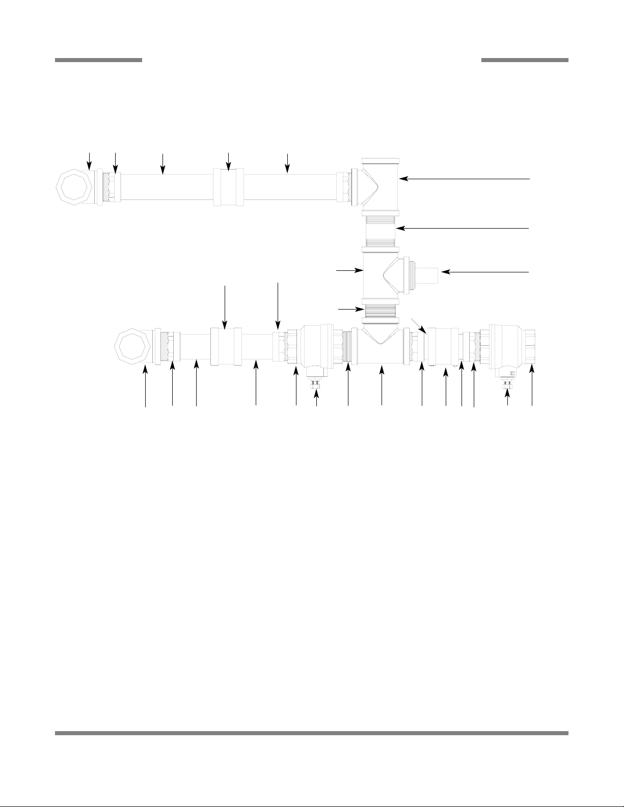
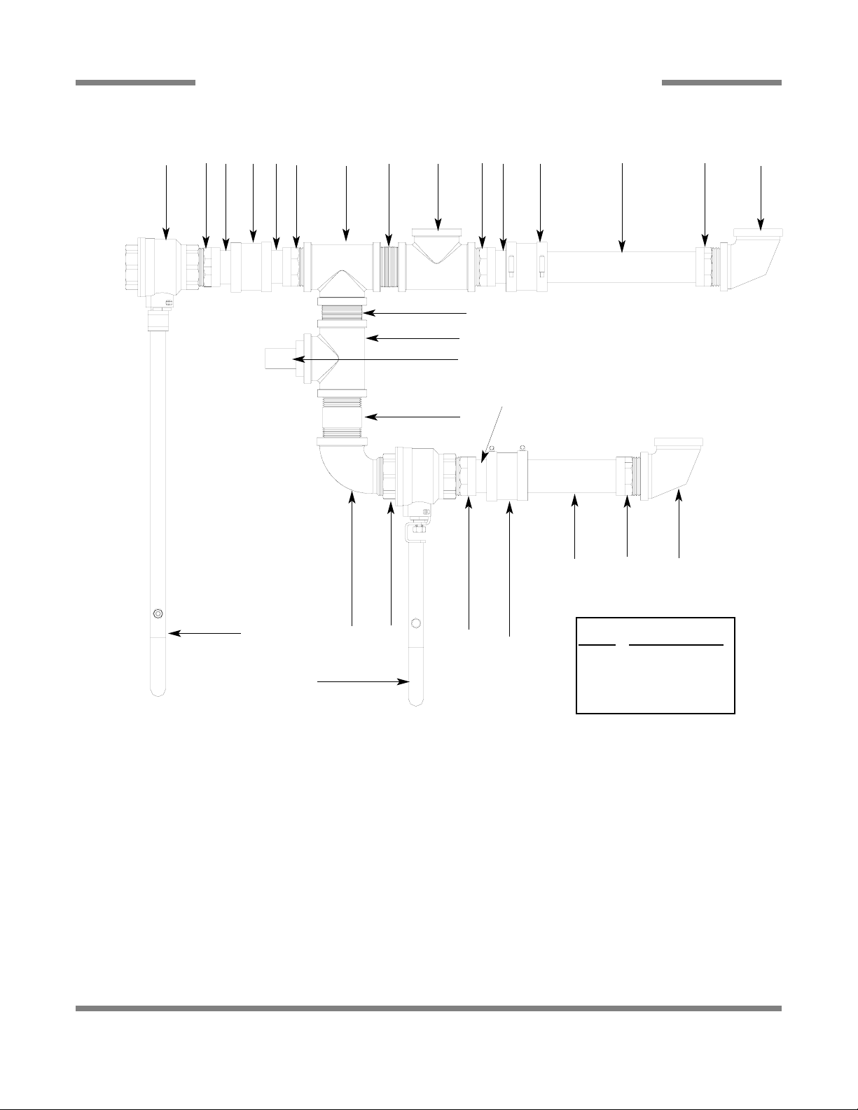
D226 STEAM BOOSTER PLUMBING ASSEMBLY
116
17
2
1
2 3 4
5
6
8
9
10
11
12
13
14
15
16
17
18
19
20
21
22
23
24
25
26
27
28
29
31
31
7
32
3330
Page 35

AJ-44C Series Technical Manual 7610-001-76-22
Issued: 03-21-2006 Revised: N/A
SECTION 5: PARTS SECTION
D226 STEAM BOOSTER PLUMBING ASSEMBLY (CONTINUED)
117
ITEM QTY DESCRIPTION Mfg. No.
1 1 Water Pressure Regulator, 3/4” 04820-100-01-06
2 2 Nipple, Brass, 3/4” NPT x 6” Long 05700-001-26-74
3 2 U-Bolt, 6”, 5/8”-11 Thread 05306-458-01-04
4 1 Platform Weldment 05700-002-78-02
5 1 Heat Exchanger 04420-100-01-05
6 1 Steam Trap, 3/4” 06680-500-02-77
7 1 Bushing, 2” NPT x 3/4” NPT, Black Iron 04730-902-06-34
8 2 Elbow, 3/4” NPT, Brass 04730-206-13-00
9 6 Nipple, 1” NPT, Close, Black Iron 04730-907-08-34
10 2 Union, 3/4” NPT, Brass 04730-212-05-00
11 2 Bushing, 2” NPT x 3/4” NPT, Brass 04730-202-18-00
12 4 Nipple, 3/4” NPT x 1-3/8” Long 04730-207-34-00
13 1 Bushing, Hex 3/4” M x 1/2” F, Brass 04730-002-56-27
14 1 Y-Strainer, 1” NPT, Black Iron 04730-217-02-32
15 2 Pressure Gauge 06685-111-88-34
16 1 Steam Relief Valve 04820-100-07-06
17 2 Nipple, 3/4” NPT x 4” Long, Brass 04730-207-05-00
18 2 Tee, 3/4” NPT x 3/4” NPT x 3/4” NPT, Brass 04730-211-01-34
19 1 Bushing, 2” NPT x 1” NPT, Black Iron 04730-002-94-51
20 3 Elbow, 90°, 1” NPT, Black Iron 04730-906-03-34
21 2 Nipple, 1” NPT x 4” Long, Black Iron 04730-907-09-34
22 1 Elbow, 90°, Street, 3/4” NPT, Black Iron 04730-011-87-37
23 1 Nipple, Pigtail, 1/4” NPT 04730-907-14-34
24 1 Coupling, 1/4” NPT x 1/4” NPT 04730-904-01-34
25 1 Steam Solenoid Valve, 240VA 04820-100-29-34
25 1 Steam Solenoid Valve, 200VA 04820-002-93-66
25 1 Steam Solenoid Valve (ASCO) 04820-002-90-26
26 1 Tee, 3/4” NPT x 3/4” NPT x 1/4” NPT, Brass 04730-211-04-00
27 1 Valve, Test Cock, 1/4” NPT 04810-011-72-67
28 1 Tee, 1” NPT x 1” NPT x 1” NPT, Black Iron 04730-911-01-34
29 1 Valve, Safety Relief 1” NPT 04820-100-01-35
30 1 Tee, 1” NPT x 1” NPT x 1/4” NPT, Black Iron 04730-911-01-00
31 2 Union, 3/4” NPT, Black Iron 04730-912-01-00
32 2 Nipple, 3/4” NPT x 2” Long, Brass 04730-207-46-00
33 2 Nipple, 3/4” NPT, Close, Black Iron 04730-907-01-00
Page 36

AJ-44C Series Technical Manual 7610-001-76-22
Issued: 03-21-2006 Revised: N/A
SECTION 5: PARTS SECTION
GO*BOX COMPONENTS
118
A GO*BOX is a kit of the most needed parts for a particular model or model familly to successfully effect a repair in the first call
90% or more of the time.
The following components may be ordered together using part number 06401-002-14-99.
QTY DESCRIPTION Mfg. No.
1 Drive Motor Contactor 05945-111-68-38
1 Contactor, Wash Heater, 3 ph, 3 pole 05945-002-24-70
1 Contactor, Wash Heater, 1 ph, 4 pole 05945-111-68-37
2 Final Rinse Arm End Cap 05700-011-35-92
1 Float Switch, Dual, Wash & Prewash 06680-121-70-71
1 Gasket, Pawl Bar Gutter 05330-011-68-55
1 Gauge, Pressure 06685-111-88-34
6 Glide, Door Edge 05700-111-70-92
2 Magnet, Door Reed Switch 05930-111-51-68
2 O Ring, Prewash Manifold 05330-400-12-08
2 O Ring, Wash Manifold 05330-011-74-56
1 Overload, Drive Motor 05945-111-68-39
1 Overload, Wash Motor 05945-111-68-40
1 Relay,120v, 3 PDT 05945-111-72-51
1 Relay,120v,50/60Hz 3A Control 05945-111-35-19
1 Repair Kit, 3/4" Vacuum Breaker 04820-001-60-57
4 Roller, Pawl Bar 05700-011-68-16
1 Seal Kit for Wash and Prewash pump 05330-011-71-98
2 Solenoid Valve, Fill & Rinse 04810-100-53-00
2 Switch, Power 05930-011-49-55
2 Switch, Reed, Actuator (NC) 05930-111-68-44
1 Switch, Reed, Door (NO) 05930-111-68-86
1 Thermometer, 48" Capillary 06685-111-68-48
1 Thermometer, 96" Capillary 06685-111-68-49
2 Thermostat, Wash High Limit 05930-121-71-36
2 Thermostat, Wash Regulating 05930-121-67-72
1 Transformer,150VA 05950-011-68-35
1 Valve, Ball 1 1/2" NPT 04820-111-71-46
Page 37
AJ-44C Series Technical Manual 7610-001-76-22
Issued: 03-21-2006 Revised: N/A
SECTION 5: PARTS SECTION
BC FERRIES OPTIONS
119
Screw, 10-32 x 3/8” Truss Head
05305-173-12-00
Complete Lower Wash Arm Assembly
05700-003-03-70
End Cap
05700-011-67-11
Lanyard
05340-011-72-46
Locknut, 10-24 with Nylon Insert
05310-373-01-00
Lower Wash Arm Manifold Weldment
05700-031-67-29
SERVICE NOTE: When replacing the 10-32 screws in the End Caps, it is recommended that a
thread locking fluid be used to ensure that the screws do not back out during normal operation.
Wash Arm Lock Down Assembly
05700-003-03-64
Lower Wash Arm Support
Bracket Weldment
05700-003-03-59
Secured with Locknut, 1/4”-20
with Nylon Insert
05310-374-01-00
Key Lock Weldment
05700-003-03-58
Wash Fill Tube Weldment
05700-003-03-69
Gasket
05330-111-42-81
Back Strainer Weldment
05700-003-03-55
Front Strainer Weldment
05700-003-03-56
Rinse Drain Control Plate
05700-011-68-70
Rinse Tray Weldment
05700-003-03-67
Page 38

120
SECTION 6:
ELECTRICAL SCHEMATICS
Page 39
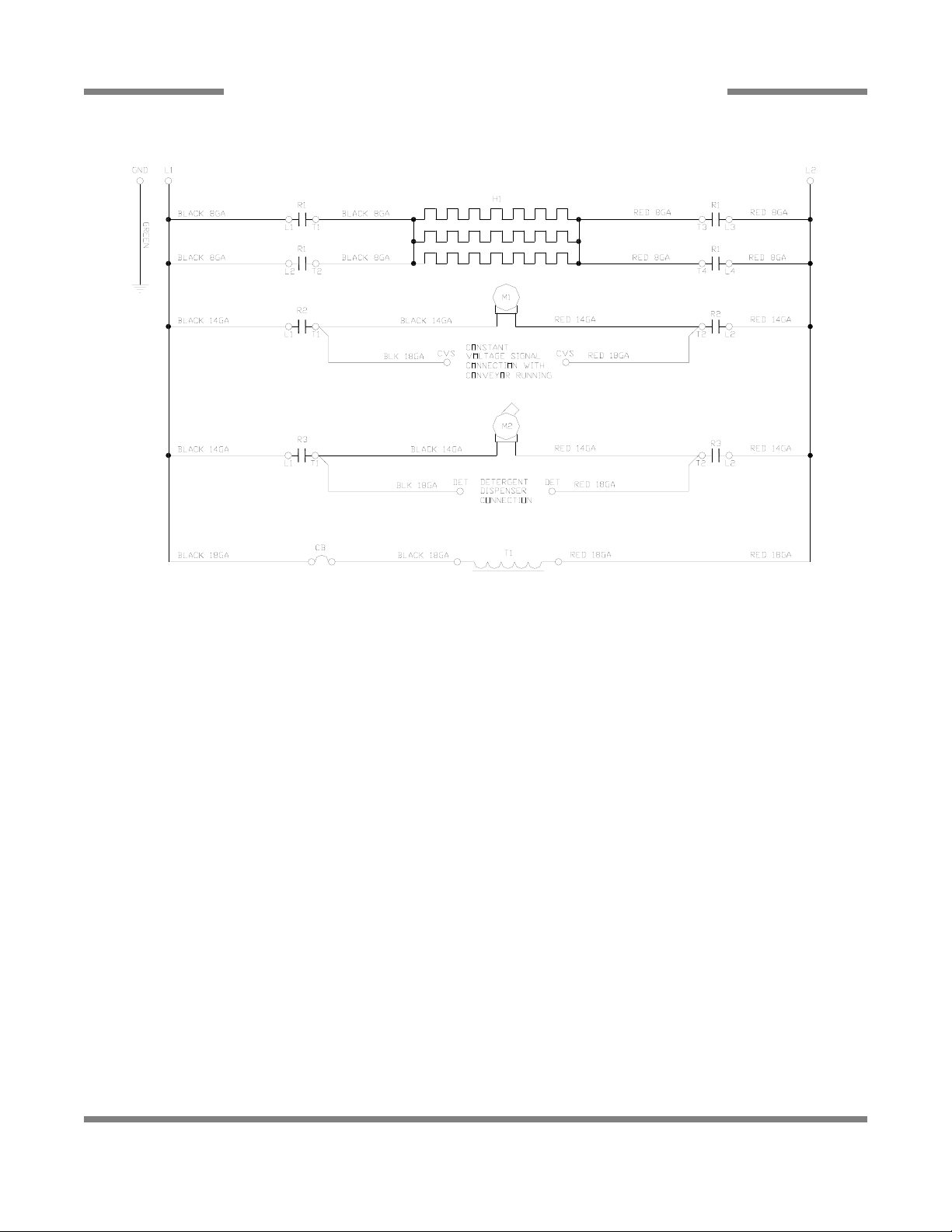
AJ-44C Series Technical Manual 7610-001-76-22
Issued: 03-21-2006 Revised: N/A
SECTION 6: ELECTRICAL SCHEMATICS
AJ-44CE/CEL (200-208-220-230 VOLTS/50-60HZ/1 PHASE) PRIMARY SIDE
121
Page 40

AJ-44C Series Technical Manual 7610-001-76-22
Issued: 03-21-2006 Revised: N/A
SECTION 6: ELECTRICAL SCHEMATICS
AJ-44CE/CEL (200-208-220-230 VOLTS/50-60HZ/1 PHASE) SECONDARY SIDE
122
Page 41
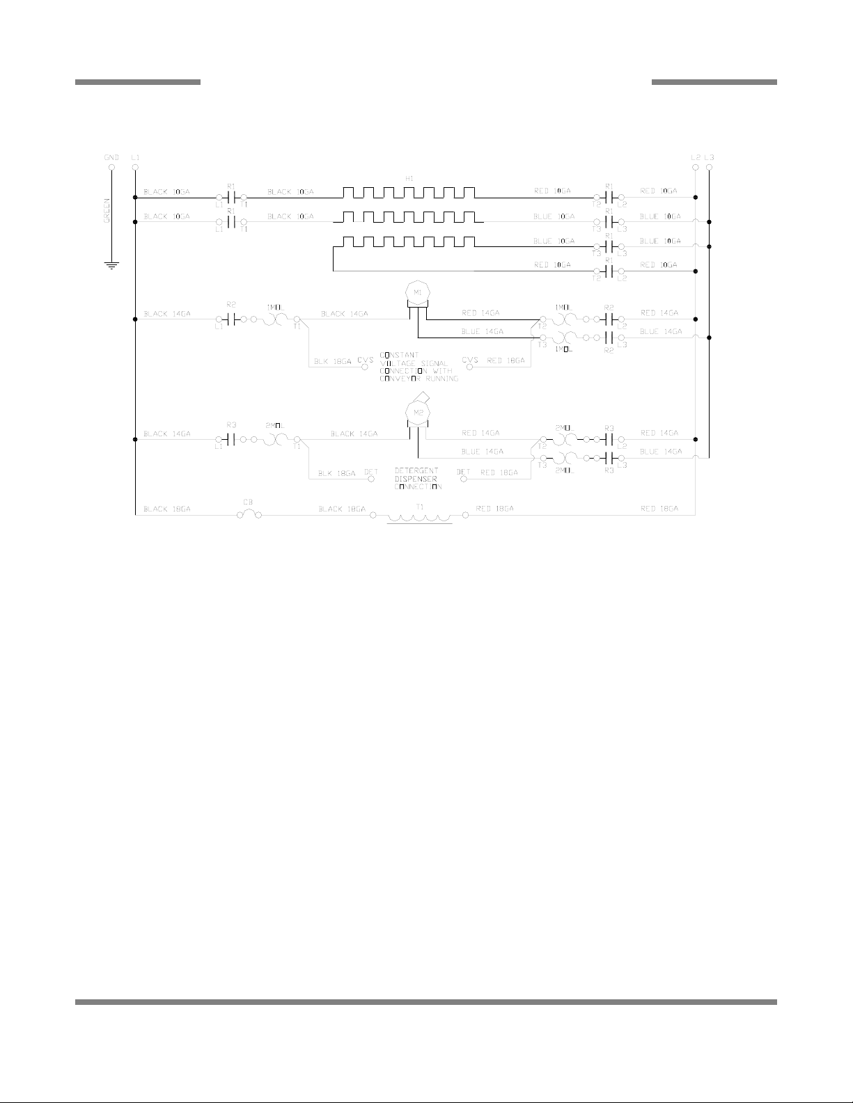
AJ-44C Series Technical Manual 7610-001-76-22
Issued: 03-21-2006 Revised: N/A
SECTION 6: ELECTRICAL SCHEMATICS
AJ-44CE/CEL (200-208-220-230 VOLTS/50-60HZ/3 PHASE) PRIMARY SIDE
123
Page 42

AJ-44C Series Technical Manual 7610-001-76-22
Issued: 03-21-2006 Revised: N/A
SECTION 6: ELECTRICAL SCHEMATICS
AJ-44CE/CEL (200-208-220-230 VOLTS/50-60HZ/3 PHASE) SECONDARY SIDE
124
Page 43

AJ-44C Series Technical Manual 7610-001-76-22
Issued: 03-21-2006 Revised: N/A
SECTION 6: ELECTRICAL SCHEMATICS
AJ-44CE/CEL (380-460-600 VOLTS/60 HZ/3 PHASE) PRIMARY SIDE
125
Page 44

AJ-44C Series Technical Manual 7610-001-76-22
Issued: 03-21-2006 Revised: N/A
SECTION 6: ELECTRICAL SCHEMATICS
AJ-44CE/CEL (380-460-600 VOLTS/60 HZ/3 PHASE) SECONDARY SIDE
126
Page 45

AJ-44C Series Technical Manual 7610-001-76-22
Issued: 03-21-2006 Revised: N/A
SECTION 6: ELECTRICAL SCHEMATICS
AJ-44CE/CEL (380-415 VOLTS/50 HZ/3 PHASE) PRIMARY SIDE
127
 Loading...