

Jackson AAJ-44CGP Service Manual

AJ-44 RACK CONVEYOR DISHMACHINE SERIES
INSTALLATION/OPERATION &
TECHNICAL MANUAL
FOR JACKSON MODELS:
AJ-44CE
AJ-44CEL
AJ-44CGP
AJ-44CS
AJ-44CSL
AJ-66CE
AJ-66CEL
AJ-66CGP
AJ-66CS
AJ-66CSL
AJ-80CE
AJ-80CEL
AJ-80CS
AJ-80CSL
August 7, 2015
P/N 07610-001-76-22 (Revision M)
Jackson MSC LLC.
P.O. Box 1060
Barbourville, KY. 40906
(888) 800-5672
Fax: (606) 523-1799
www.jacksonmsc.com

MANUFACTURERS WARRANTY
ONE YEAR LIMITED PARTS & LABOR WARRANTY
ALL NEW JACKSON DISHWASHERS ARE WARRANTED TO THE ORIGINAL PURCHASER TO BE FREE FROM
DEFECTS IN MATERIAL OR WORKMANSHIP, UNDER NORMAL USE AND OPERATION FOR A PERIOD OF (1) ONE
YEAR FROM THE DATE OF PURCHASE, BUT IN NO EVENTTO EXCEED (18) EIGHTEEN MONTHS FROM THE DATE
OF SHIPMENT FROM THE FACTORY.
Jackson MSC agrees under this warranty to repair or replace , at its discretion, any original part which fails under normal use due to faulty
material or workmanship during the warranty period, providing the equipment has been unaltered, and has been properly installed, maintained and operated in accordance with the applicable factory instruction manual furnished with the machine and the failure is reported to
the authorized service agency within the warranty period. This includes the use of factory specified genuine replacement parts, purchased
directly from a Jackson authorized parts distributor or service agency. Use of generic replacement parts may create a hazard and void warranty certification.
The labor to repair or replace such failed part will be paid by Jackson MSC, within the continental United States, Hawaii and Canada, during
the warranty period provided
service. Any repair work by persons other than a Jackson MSC authorized service agency is the sole responsibility of the customer. Labor
coverage is limited to regular hourly rates, overtime premiums and emergency service charges will not be paid by Jackson MSC.
Accessory components not installed by the factory carry a (1) one year parts warranty only. Accessory components such as table limit switches, pressure regulators, pre rinse units, etc. that are shipped with the unit and installed at the site are included. Labor to repair or replace
these components is not covered by Jackson MSC.
This warranty is void if failure is a direct result from shipping, handling, fire, water, accident, misuse, acts of god, attempted repair by unauthorized persons, improper installation, if serial number has been removed or altered, or if unit is used for purpose other than it was originally intended.
a Jackson MSC authorized service agency, or those having prior authorization from the factory, performs the
TRAVELLIMITATIONS
Jackson MSC limits warranty travel time to (2) two hours and mileage to (100) one hundred miles. Jackson MSC will not pay for travel time
and mileage that exceeds
WARRANTY REGISTRATION
To register your product go to www.jacksonwws.com or call 1-888-800-5672. Failure to register your product will void the warranty.
REPLACEMENT PARTS WARRANTY
Jackson replacement parts are warranted for a period of 90 days from the date of installation or 180 days from the date of shipment from the
factory, which ever occurs first.
PRODUCT CHANGES AND UPDATES
Jackson MSC reserves the right to make changes in design and specification of any equipment as engineering or necessity requires.
THIS IS THE ENTIRE AND ONLY WARRANTY OF JACKSON MSC. JACKSON’S LIABILITY ON ANY CLAIM OF ANY KIND, INCLUDING
NEGLIGENCE, WITH RESPECT TO THE GOODS OR SERVICES COVERED HEREUNDER, SHALL IN NO CASE EXCEED THE PRICE
OF THE GOODS OR SERVICES OR PARTTHEREOF WHICH GIVES RISE TO THE CLAIM.
THERE ARE NO WARRANTIES, EXPRESSED OR IMPLIED, INCLUDING FOR FITNESS OR MERCHANTABILITY, THAT ARE NOT SET
FORTH HEREIN, OR THAT EXTEND BEYOND THE DURATION HEREOF. UNDER NO CIRCUMSTANCES WILL JACKSON MSC BE
LIABLE FOR ANY LOSS OR DAMAGE, DIRECT OR CONSEQUENTIAL, OR FOR THE DAMAGES IN THE NATURE OF PENALTIES,
ARISING OUT OF THE
ITEMS NOT COVERED
this, or any fees such as those for air or boat travel without prior authorization.
USE OR INABILITY TO USE ANY OF ITS PRODUCTS.
This warranty does not cover cleaning or deliming of the unit or any component such as, but not limited to, wash arms, rinse arms or strainers at anytime. Nor does it cover adjustments such as, but not limited to timer cams, thermostats or doors, beyond 30 days from the date
of installation. In addition, the warranty will only cover the replacement of wear items such as curtains, drain balls, door guides or gaskets
during the first 30 days after installation. Also, not covered are conditions caused by the use of incorrect (non-Commercial) grade detergents,
incorrect water temperature or pressure, or hard water conditions.
i
REVISION/
L
07-17-2015
KAP
N/A
QOF-386
Updated drawing & p/n for suction weldment strainer on pg. 108
M
08-04-2015
KAP
Pg. 96, Updated Final Rinse Manifold Weldment
P/N to 05700-031-74-88.
PAGE
D 05-14-2004 CBW N/A Added exhaust fan hook-up schematic.
E 03-08-2005 MAW 7096
F 01-13-2006 CBW 7470 Added service kits and maintenance instructions.
G 01-26-2006 MAW 7600 Added Gas Exhaust Fan Schematic & component kits.
REVISION
DATE
MADEBYAPPLICABLE
ECN
DETAILS
Updated installation instructions. Added 3 instruction sheets for
limit switches. Added instruction sheet for curtain installation.
Changed layout.
H 03-21-2006 MAW
98 04-19-2007 MAW 7898
35 & 36 05-03-2007 MAW 7913
5 thru 22, 111 08-29-2007 MAW N/A
I 10-09-2009 KJS 8044
J 01-16-2014
MHH
7571, 7558
7634
QOF NDB-219
K 03-23-2015 KAP N/A
Added themostat replacement kits. Added vent cowl assembly for
hooded side loader. Replaced rinse drain weldment. Added scrap
basket strainer kit.
Added 09905-003-32-20 fan load decal to the exhaust fan control
kit. Added warranty pages and service centers listings.
Added instructions and all necessary information for change of
sanitization mode.
Updated dimension pages. Removed alternate table limit switches.
Changed the part from a weldment (05700-021-67-50) to a
casting (09515-003-58-12).
Updated manufacturer information.
Updated temperature on pg's 13, 14, 19 and 20.
Updated pressure regulator info on pg. 30 and 45.
Updated gas drawings, pg's 7, 8, 13, 14, 19, 20
ii

NOMENCLATURE FOR THE MODELS COVERED IN THIS MANUAL
AJ-44CSL
AJ = AJ series of rack conveyors
44 = 44” wide machine
66 = 66” wide machine
80 = 80” wide machine
CE = Electrically heated, hot water sanitizing machine
CEL = Electrically heated, chemical sanitizing machine
CS = Steam heated, hot water sanitizing machine
CSL = Steam heated, chemical sanitzing machine
CGP = Gas heated, hot water sanitizing machine
Model:
Serial No.:
Installation Date:
Service Rep. Name:
Phone No.:
Jackson WWS, INC provides technical support for all
of the dishmachines detailed in this manual. We
strongly recommend that you refer to this manual
before making a call to our technical support staff.
Please have this manual with you when you call so
that our staff can refer you, if necessary, to the proper page. Technical support is available from 8:00
a.m. to 5:00 p.m. (EST), Monday through Friday.
Technical support is not available on holidays.
Contact technical support toll free at 1-888-800-
5672. Please remember that technical support is
is available for service personnel only.
iii

TABLE OF CONTENTS
SECTION
I. SPECIFICATION INFORMATION
DESCRIPTION PAGE
Operating Characteristics 2
Electrical Requirements 3
AJ-44 Gas - Left to Right 7
AJ-44 Gas - Right to Left 8
AJ-66 Gas - Left to Right 13
AJ-66 Gas - Right to Left 14
AJ-80 Gas - Left
AJ-80 Gas - Right to Left 20
to Right 19
4sretemaraP retsooB maetS 622D
5thgiR ot tfeL - cirtcelE 44-JA
6tfeL ot thgiR - cirtcelE 44-JA
9thgiR ot tfeL - maetS 44-JA
01tfeL ot thgiR - maetS 44-JA
11thgiR ot tfeL - cirtcelE 66-JA
21tfeL ot thgiR - cirtcelE 66-JA
51thgiR ot tfeL - maetS 66-JA
61tfeL ot thgiR - maetS 66-JA
71thgiR ot tfeL - cirtcelE 08-JA
81tfeL ot thgiR - cirtcelE 08-JA
12thgiR ot tfeL - maetS 08-JA
22tfeL ot thgiR - maetS 08-JA
32snoisnemiD )thgiR ot tfeL( redaoL ediS
42snoisnemiD )tfeL ot thgiR( redaoL ediS
52snoisnemiD )dellatsnI( redaoL ediS
62snoisnemiD retsooB maetS 622D
72sgniwarD eniL gnibmulP retsooB maetS 622D
82snoisnemiD retsooB saG dna cirtcelE lacipyT
II. INSTALLATION & OPERATION INSTRUCTIONS
Installation Instructions 30
Deliming Operations 33
Detergent Control 50
III. PREVENTATIVE MAINTENANCE
General Maintenance 53
D226 Maintenance 54
IV. TROUBLESHOOTING SECTION
Common Problems 58
D226 Common Problems 60
43levarT fo noitceriD SC/EC44-JA eht gnignahC
04smargaiD noitallatsnI niatruC
14snoitcurtsnI noitarepO & noitallatsnI redaoL ediS
24snoitcurtsnI noitarepO & noitallatsnI retsooB maetS 622D
44noitallatsnI esoH royevnoC saG
64snoitcurtsnI gnitarepO enihcamhsiD
84edoM oitazitinaS lauD gnignahC
15snoitcurtsnI noitallatsnI hctiwS timiL etalP rekirtS
55raeG evirD rof trahC noitacirbuL
65ecnanetniaM evitatneverP recudeR raeG rotoM evirD
iv

V. PARTS SECTION
Motor Overload Chart 66
Heater Assembly 67
Thermostats/Dress Panels 69
Wash Section Plumbing 71
Drain Quench Assembly 90
Motor Assemblies 91
Curtains/Tub Magnets 95
Final Rinse Assembly 96
Drive Assembly 97
Door Assemblies 99
AJ-44 Rack Rail Assembly 103
Strainers 108
SIDE LOADER SECTION
D226 STEAM BOOSTER SECTION
Go*Box Components 118
BC Ferries Options 119
TABLE OF CONTENTS
PARTS
nemdleW pmuP hsaW & hsawerP
26ylbmessA xoB lortnoC 44-JA
46ylbmessA xoB lortnoC 08-JA/66-JA
07ylbmessA gnibmulP hsawerP
27gnibmulP gnimocnI noitpO retsooB cirtcelE lanretxE
37gnibmulP teltuO noitpO retsooB cirtcelE lanretxE
47noitpO gnibmulP KRPWnoitpO rotserrA remmaH retaW
57stiK straP riapeR rekaerB muucaVTPN ”4/3 & evlaV dioneloS ”4/3
67ylbmessA lioC knaT hsaW tinU maetS
77)thgiR ot tfeL( gnibmulP maetS
87)tfeL ot thgiR( gnibmulP maetS
97)sledoMPGC( ylbmessA lioC saG
08)sledoMPGC( ylbmessA knaT retsooB esniR
18)sledoMPGC( ylbmessA pmuP gnitalucriceR
28)sledoMPGC( snoitcennoC esoH
38)sledoMPGC( ylbmessA gnibmulP lliF/hsaW
48)sledoMPGC( ylbmessA gnibmulP redaeH esniR
58seilbmessA gnibmulP niarD seireS 44-JA
68 seilbmessA gnibmulP niarD 66-JA
78seilbmessA gnibmulP niarD 08-JA
88)sledoMPGC( )thgiR ot tfeL( ylbmessA gnibmulP niarD 66-JA
98)sledoMPGC( )tfeL ot thgiR( ylbmessA gnibmulP niarD 66-JA
29st
39ylbmessA mrA hsaW rewoL
49ylbmessA mrA hsaW reppU/mrA hsawerP
001stnenopmoC suoenallecsiM raB lwaP
101seilbmessA raB lwaP 66-JA & 44-JA
201seilbmessA raB lwaP 08-JA
401seilbmessA liaR kcaR 66-JA
501seilbmessA liaR kcaR 08-JA
601stnemdleW & straP suoenallecsiM
701stnemdleW troppuS reniartS/sdlofinaM
901steksaB parcS/stnenopmoC hctiwS taolF
011noitpO poocS tneV/ylbmessA lwoC tneV
111hctiwS timiL elbaT/lortnoC naF tsuahxE
eniartS/stnemecalpeR geL/ylbmessA kcarT redaoL ediS
211r
311tengaM/tekcarB raB lwaP/seilbmessA raB lwaPredaoL ediS
411noitpO lwoC tneV redaoL ediS
511ylbmessA xoB lortnoC
611ylbmessA gnibmulP
v

VI. ELECTRICAL SCHEMATICS
AJ-44CE/CEL
AJ-44CS/CSL
AJ-66CE/CEL & AJ-80CE/CEL
AJ-66CS/CSL & AJ-80CS/CSL
AJ-44CGP
AJ-66CGP, AJ-80CGP
TABLE OF CONTENTS
ELECTRICAL SCHEMATICS
diS yramirP esahP 1 ,zH 06/05 ,tloV 032-002
diS yramirP esahP 1 ,zH 06/05 ,tloV 032-002
121ediS yramirP esahP 1 ,zH 06/05 ,tloV 032-002
221ediS yradnoceS esahP 1 ,zH 06/05 ,tloV 032-002
321ediS yramirP esahP 3 ,zH 06/05 ,tloV 032-002
421ediS yradnoceS esahP 3 ,zH 06/05 ,tloV 032-002
521ediS yramirP esahP 3 ,zH 06 ,tloV 006-064-083
621ediS yradnoceS esahP 3 ,zH 06 ,tloV 006-064-083
721ediS yramirP esahP 3 ,zH 05 ,tloV 514-083
821ediS yradnoceS esahP 3 ,zH 05 ,tloV 514-083
921ediS yramirP esahP 3 ,zH 05 ,tloV 044
031ediS yradnoceS esahP 3 ,zH 05 ,tloV 044
131ediS yramirP eriW 5 ,esahP 3 ,zH 05 ,tloV 044
231ediS yradnoceS eriW 5 ,esahP 3 ,zH 05 ,tloV 044
331ediS yramirP esahP 1 ,zH 06/05 ,tloV 032-002
431ediS yradnoceS esahP 1 ,zH 06/05 ,tloV 032-002
531ediS yramirP esahP 3 ,zH 06/05 ,tloV 032-002
631ediS yradnoceS esahP 3 ,zH 06/05 ,tloV 032-002
731ediS yramirP esahP 3 ,zH 06 ,tloV 006-064-044-514-083
831ediS yradnoceS esahP 3 ,zH 06 ,tloV 006-064-044-514-083
931e
041ediS yradnoceS esahP 1 ,zH 06/05 ,tloV 032-002
141ediS yramirP esahP 3 ,zH 06/05 ,tloV 032-002
241ediS yradnoceS esahP 3 ,zH 06/05 ,tloV 032-002
341ediS yramirP esahP 3 ,zH 06 ,tloV 006-064-083
441ediS yradnoceS esahP 3 ,zH 06 ,tloV 006-064-083
541ediS yramirP esahP 3 ,zH 05 ,tloV 044-514-083
641ediS yradnoceS esahP 3 ,zH 05 ,tloV 044-514-083
741e
841ediS yradnoceS esahP 1 ,zH 06/05 ,tloV 032-002
941ediS yramirP esahP 3 ,zH 06/05 ,tloV 032-002
051ediS yradnoceS esahP 3 ,zH 06/05 ,tloV 032-002
151ediS yramirP esahP 3 ,zH 06 ,tloV 006-064-044-514-083
251ediS yradnoceS esahP 3 ,zH 06 ,tloV 006-064-044-514-083
351ediS yramirP esahP 1 ,zH 06/05 ,tloV 032-002
451ediS yradnoceS esahP 1 ,zH 06/05 ,tloV 032-002
551ediS yramirP esahP 3 ,zH /05 ,tloV 032-002
651ediS yradnoceS esahP 3 ,zH /05 ,tloV 032-002
751ediS yramirP esahP 3/zH 06/tloV 064
851ediS yramirP esahP 3/zH 06/tloV 064
951ediS yramirP esahP 1 ,zH 06/05 ,tloV 032-002
061ediS yradnoceS esahP 1 ,zH 06/05 ,tloV 032-002
161ediS yramirP esahP 3 ,zH 06/05 ,tloV 032-002
261ediS yradnoceS esahP 3 ,zH 06/05 ,tloV 032-002
361ediS yramirP esahP 3 ,zH 06/05 ,tloV 064
461ediS yradnoceS esahP 3 ,zH 06/05 ,tloV 064
561retsooB maetS 622D/redaoL ediS royevnoC
661scitamehcS pU-kooH naF tsuahxE
VIII. MAINTENANCE & REPAIR CENTERS 177
vi

1
SECTION 1:
SPECIFICATION INFORMATION

SECTION 1: SPECIFICATION INFORMATION
OPERATING CHARACTERISTICS
2
RACKS PER HOUR:
AJ-44-66-80CE/CS/CGP 248
AJ-44-66-80CEL/CSL 234
DISHES OR GLASSES PER HOUR:
AJ-44-66-80CE/CS/CGP 6200
AJ-44-66-80CEL/CSL 5850
PREWASH TANK CAPACITY (GALLONS):
AJ-66CE/CEL/CS/CSL/CGP 16
AJ-80CE/CEL/CS/CSL/CGP 16
WASH TANK CAPACITY (GALLONS):
AJ-44-66-80CE/CS/CGP 15.4
PREWASH PUMP CAPACITY (GPM):
AJ-66CE/CEL/CS/CSL/CGP 120
AJ-80CE/CEL/CS/CSL/CGP 270
WASH PUMP CAPACITY
GALLONS PER MINUTE (ALL MODELS): 270
VENTING REQUIREMENTS (CFM)(100% CAP.):
INPUT END 200
OUTPUT END 400
TOTAL 600
CONVEYOR SPEED (FPM):
AJ-44-66-80CE/CS/CGP MACHINES 6.9
AJ-44-66-80CEL/CSL MACHINES 6.5
GALLONS PER RACK:
AJ-44-66-80CE/CS/CGP MACHINES .94
AJ-44-66-80CEL/CSL MACHINES 1.00
WATER TEMPERATURES:
AJ-44-66-80CE/CS/CGP MODELS:
PREWASH (RECOMMENDED) 110-140°F
WASH (MINIMUM) 160°F
RINSE (MINIMUM) 180°F
AJ-44-66-80CEL/CSL MODELS:
PREWASH (RECOMMENDED) 110-140°F
WASH (MINIMUM) 140°F
RINSE (MINIMUM) 140°F
FLOW PRESSURE (PSI) 20±5
FLOWRATE (GPM):
AJ-44-66-80CE/CS/CGP 3.9
AJ-44-66-80CEL/CSL 3.9
MINIMUM CHLORINE (PPM)
AJ-44-66-80CEL/CSL MODELS ONLY: 50
STEAM COIL TANK HEAT (CS/CSL MODELS ONLY):
STEAM INLET PRESSURE (PSIG) 10-20
STEAM CONNECTION NPT 3/4”
CONSUMPTION @ 15 PSIG (lbs/hr):
AJ-44-66-80CS/CSL 60
MOTOR ELECTRICAL CHARACTERISTICS:
DRIVE MOTOR HP 1/4
WASH MOTOR HP 2
POWER RINSE MOTOR HP 2
PREWASH MOTOR HP:
AJ-66 MODELS 1
AJ-80 MODELS 2
NOTE: Typical Electrical Circuit is based upon (1) 125% of
the full amperage load of the machine and (2) typical
fixed-trip circuit breaker sizes as listed in the NEC 2002
Edition. Local codes may require more stringent protection than what is displayed here. Always verify with your
electrical service contractor that your circuit protection is
adequate and meets all applicable national and local
codes. These numbers are provided in this manual simply for reference and may change without notice at any
given time.

SECTION 1: SPECIFICATION INFORMATION
ELECTRICAL REQUIREMENTS
3
AJ-44CE/CEL MODELS
TYPICAL
TOTAL ELECTRICAL
VOL
TS PH HZ AMPS CIRCUIT
208 3 50 55 A 70 AMP
220 3 50 49 A 70 AMP
230 3 50 51 A 70 AMP
380 3 50 29 A 40 AMP
415 3 50 28 A 35 AMP
440 3 50 28 A 35 AMP
208 1 60 83 A 110 AMP
230 1 60 76 A 100 AMP
200 3 60 47 A 60 AMP
208 3 60 49 A 70 AMP
230 3 60 45 A 60 AMP
380 3 60 29 A 40 AMP
460 3 60 23 A 30 AMP
600 3 60 19 A 25 AMP
AJ-44CGP MODELS
TYPICAL
TOTAL ELECTRICAL
VOLTS PH HZ AMPS CIRCUIT
208 1 60 12 A 15 AMP
230 1 60 11 A 15 AMP
208 3 60 8 A 15 AMP
230 3 60 7 A 15 AMP
460 3 60 5 A 15 AMP
AJ-44CS/CSL
MODELS
TYPICAL
TOTAL ELECTRICAL
VOLTS PH HZ AMPS CIRCUIT
208 3 50 13 A 20 AMP
220 3 50 13 A 20 AMP
230 3 50 13 A 20 AMP
380 3 50 6 A 15 AMP
415 3 50 7 A 15 AMP
440 3 50 6 A 15 AMP
208 1 60 11 A 15 AMP
230 1 60 11 A 15 AMP
200 3 60 7 A 15 AMP
208 3 60 7 A 15 AMP
230 3 60 7 A 15 AMP
380 3 60 6 A 15 AMP
460 3 60 4 A 15 AMP
600 3 60 4 A 15 AMP
AJ-66CE/CEL MODELS
TYPICAL
TOTAL ELECTRICAL
VOL
TS PH HZ AMPS CIRCUIT
208 3 50 58 A 80 AMP
220 3 50 53 A 70 AMP
230 3 50 54 A 70 AMP
380 3 50 31 A 40 AMP
415 3 50 34 A 45 AMP
440 3 50 33 A 45 AMP
208 1 60 89 A 125 AMP
230 1 60 82 A 110 AMP
200 3 60 51 A 70 AMP
208 3 60 52 A 70 AMP
230 3 60 48 A 60 AMP
380 3 60 31 A 40 AMP
460 3 60 24 A 30 AMP
600 3 60 22 A 30 AMP
AJ-66CGP MODELS
TYPICAL
TOTAL ELECTRICAL
VOLTS PH HZ AMPS CIRCUIT
208 1 60 17 A 15 AMP
230 1 60 17 A 15 AMP
208 3 60 11A 15 AMP
230 3 60 11A 15 AMP
460 3 60 6 A 15 AMP
AJ-66CS/CSL
MODELS
TYPICAL
TOTAL ELECTRICAL
VOLTS PH HZ AMPS CIRCUIT
208 3 50 17 A 25 AMP
220 3 50 17 A 25 AMP
230 3 50 17 A 25 AMP
380 3 50 6A 15 AMP
415 3 50 7 A 15 AMP
440 3 50 6 A 15 AMP
208 1 60 18 A 25 AMP
230 1 60 18 A 25 AMP
200 3 60 12 A 15 AMP
208 3 60 12 A 15 AMP
230 3 60 12 A 15 AMP
380 3 60 12 A 15 AMP
460 3 60 7 A 15 AMP
600 3 60 7 A 15 AMP

SECTION 1: SPECIFICATION INFORMATION
ELECTRICAL REQUIREMENTS (CONTINUED)/D226 STEAM BOOSTER PARAMETERS
4
AJ-80CE/CEL MODELS
TYPICAL
TOTAL ELECTRICAL
VOL
TS PH HZ AMPS CIRCUIT
208 3 50 68 A 90 AMP
220 3 50 62 A 80 AMP
230 3 50 63 A 80 AMP
380 3 50 34 A 45 AMP
415 3 50 25 A 35 AMP
440 3 50 22 A 30 AMP
208 1 60 91 A 125 AMP
230 1 60 84 A 110 AMP
200 3 60 53 A 70 AMP
208 3 60 54 A 70 AMP
230 3 60 50 A 70 AMP
380 3 60 34 A 45 AMP
460 3 60 25 A 35 AMP
600 3 60 22 A 30 AMP
AJ-80CS/CSL MODELS
TYPICAL
TOTAL ELECTRICAL
VOL
TS PH HZ AMPS CIRCUIT
208 3 50 19 A 25 AMP
220 3 50 19 A 25 AMP
230 3 50 19 A 25 AMP
380 3 50 7 A 15 AMP
415 3 50 8 A 15 AMP
440 3 50 8 A 15 AMP
208 1 60 19 A 25 AMP
230 1 60 19 A 25 AMP
200 3 60 13 A 20 AMP
208 3 60 13 A 20 AMP
230 3 60 13 A 20 AMP
380 3 60 13 A 20 AMP
460 3 60 7 A 15 AMP
600 3 60 8 A 15 AMP
NOTE: Always refer to the machine data plate for specific
electrical and water requirements. The material provided
on this page is for reference only and may be subject to
change without notice.
D226 STEAM BOOSTER
ELECTRICAL REQUIREMENTS:
VOLTAGE (V) 200-230
FREQUENCY (HZ) 50/60
PHASE SINGLE
WATER REQUIREMENTS:
INCOMING WATER TEMPERATURE (MINIMUM) 110°F
FLOW PRESSURE (PSI) 20±5
STEAM REQUIREMENTS:
INCOMING STEAM PRESSURE (PSIG) 15-25
HEAT EXCHANGER SPECIFICATIONS:*
TUBESIDE WORKING PRESSURE (PSI) 125
SHELLSIDE WORKING PRESSURE (PSI) 125
TUBESIDE HYDROSTATIC TEST PRESSURE (PSI) 250
SHELLSIDE HYDROSTATIC TEST PRESSURE (PSI)
188
MAXIMUM OPERATING TEMPERATURE 295°F
MAXIMUM SHELLSIDE STEAM PRESSURE (PSI) 125
* - Indicates typical design criteria but is subject to change
without notice. For more information, contact you authorized
Jackson service representative.
STEAM RELIEF VALVE SET PRESSURE (PSI): 50
WATER OUTLET SAFETY VALVE SET PRESSURE (PSI):
125
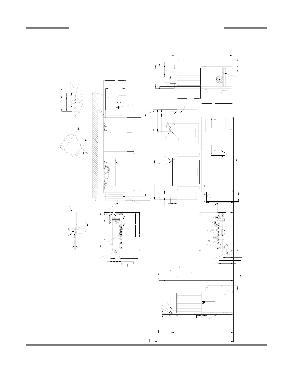
Left to Right
Drive
Unit
Left Side
Drive
Unit
Front View
Right Side
4" (102 mm) wide x 16" (406 mm)
long cutout in Vent Cowl/Splash
Shield. Shipped with Cover Plate.
Floor Sink Or Drain
With 3" (76 mm)
Minimum Drain Line
3/4" (19 mm)
Table Turndown
Flange 3/4" Max
21" (533 mm)
Rack Rail Height
Above Dishtable
1/4" (6mm) - 5/16" (8mm)
Rack Rail
Tub
Table
Use Silicone Sealer
Between Table and
Lip of Machine to
Prevent Leakage
Recommended Table Fabrication
Note: Tub Will Accept
a Table Flange
Up to 24 7/8"
(632 mm)
1
2
[15mm]
84 [2134mm]
75
1
2
[1919mm]
62
1
2
[1590mm]
34 [864mm]
29 [737mm]
6 [152mm]
7
1
2
[193mm]
21 [533mm]
25 [635mm]
25 [635mm]
10 [254mm]
7 [178mm]
D
E
A
C
A
B
18
1
2
[467mm]
25 [635mm]
4 1/2 [114mm]
4 [102mm]
Table to Table
Overall
With Doors Open
Rear of
Machine
Dish Clearance
14 [356mm]
Minimum
10" High
Table
Backsplash
Scrap
Trough
7
1
2
[190mm]
C
B
Legend
A - Machine water inlet 3/4" NPT,
180°F Hi-temp,140°F Low-temp
minimum
B - Electrical connection
C - Drain connection 1-1/2" NPT
D - Vent collar - Optional
E - Vent cowl standard
Note: All vertical dimensions are +/- 1/2"
from floor due to adjustable bullet feet.
44 [1118mm]
52 [1321mm]
60 [1524mm]
60
1
4
[1530mm]
8 [203mm]
8 [203mm]
14 [355mm]
Scrap
Trough
Minimum
21 [533mm]
B
12 [307mm]
65
1
2
[1667mm]
1 [25mm]
66
1
2
[1692mm]
13
3
4
[346mm]
7 [178mm]
SECTION 1: SPECIFICATION INFORMATION
AJ-44 ELECTRIC - LEFT TO RIGHT
5

Right to Left
Drive
Unit
Left Side
Drive
Unit
Front View
Right Side
4" (102 mm) wide x 16" (406 mm)
long cutout in Vent Cowl/Splash
Shield. Shipped with Cover Plate.
Floor Sink Or Drain
With 3" (76 mm)
Minimum Drain Line
3/4" (19 mm)
Table Turndown
Flange 3/4" Max
21" (533 mm)
Rack Rail Height
Above Dishtable
1/4" (6mm) - 5/16" (8mm)
Rack Rail
Tub
Table
Use Silicone Sealer
Between Table and
Lip of Machine to
Prevent Leakage
Recommended Table Fabrication
Note: Tub Will Accept
a Table Flange
Up to 24 7/8"
(632 mm)
1
2
[15mm]
84 [2134mm]
75
1
2
[1919mm]
62
1
2
[1590mm]
34 [864mm]
29 [737mm]
6 [152mm]
7
1
2
[193mm]
21 [533mm]
25 [635mm]
25 [635mm]
10 [254mm]
7 [178mm]
D
E
A
C
A
B
18
1
2
[467mm]
25 [635mm]
4 1/2 [114mm]
4 [102mm]
Table to Table
Overall
With Doors Open
Rear of
Machine
Dish Clearance
7
1
2
[190mm]
C
B
Legend
A - Machine water inlet 3/4" NPT,
180°F Hi-temp,140°F Low-temp
minimum
B - Electrical connection
C - Drain connection 1-1/2" NPT
D - Vent collar - Optional
E - Vent cowl standard
Note: All vertical dimensions are +/- 1/2"
from floor due to adjustable bullet feet.
44 [1118mm]
52 [1321mm]
60 [1524mm]
60
1
4
[1530mm]
8 [203mm]
8 [203mm]
21 [533mm]
B
12 [307mm]
65
1
2
[1667mm]
1 [25mm]
66
1
2
[1692mm]
13
3
4
[349mm]
7 [178mm]
A
SECTION 1: SPECIFICATION INFORMATION
AJ-44 ELECTRIC - RIGHT TO LEFT
6
Front View
Left Side
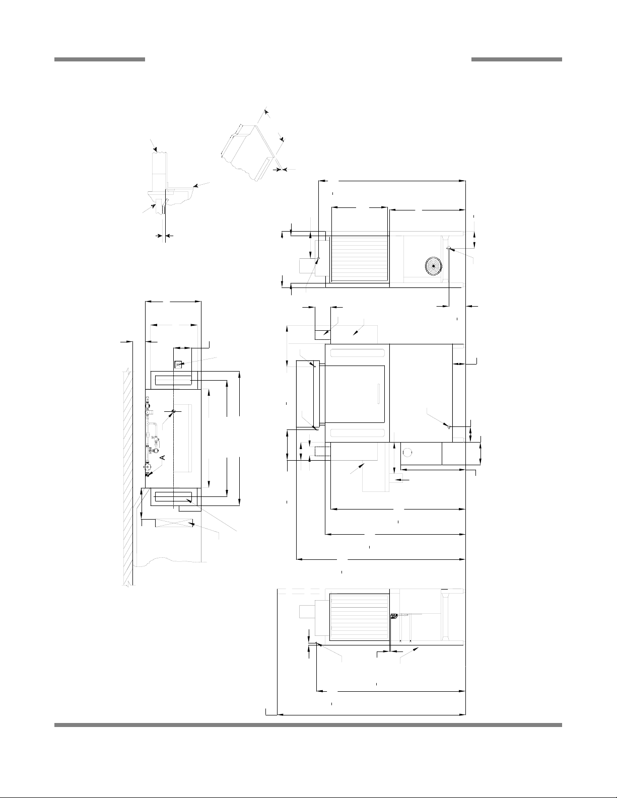
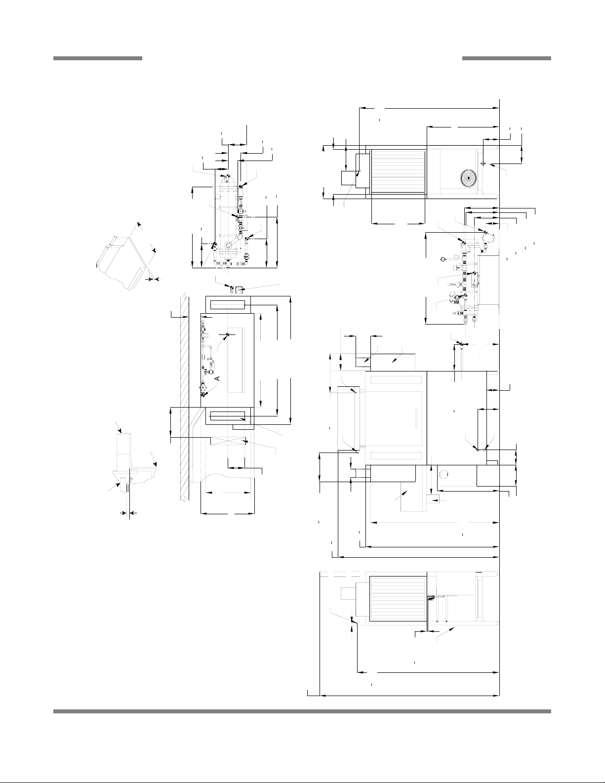
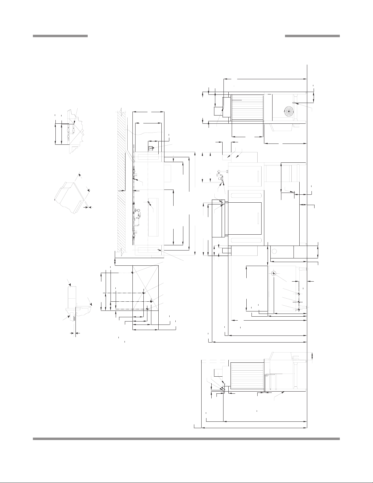
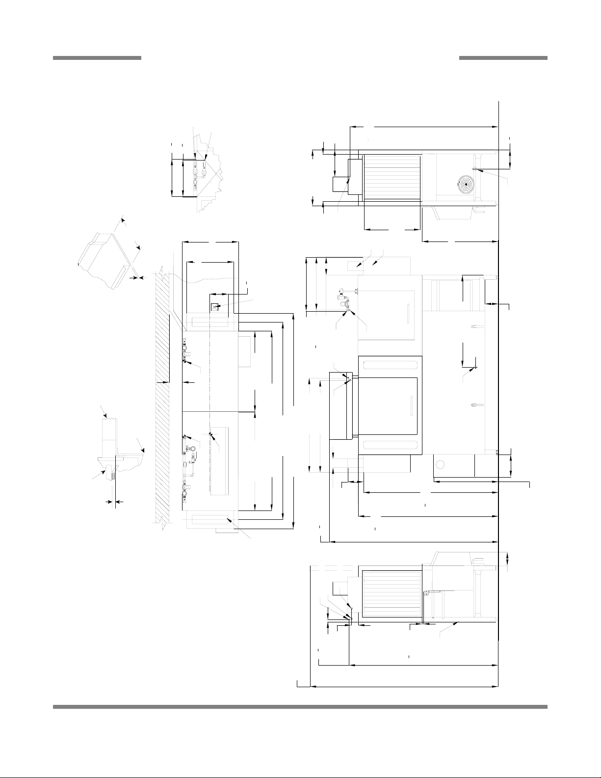
SECTION 1: SPECIFICATION INFORMATION
AJ-44 GAS - LEFT TO RIGHT
Note: Tub Will Accept
[527mm]
4
3
[375mm]
4
3
20
[298mm]
4
3
[222mm]
4
3
8
14
11
[1684mm]
1
4
66
12 [307mm]
25 [635mm]
Dish Clearance
34 [864mm]
[190mm]
1
2
7
J
H
[185mm]
1
4
7
30 [763mm]
F
G
With 3" (76 mm)
Floor Sink Or Drain
25 [635mm]
21 [533mm]
Minimum Drain Line
B
C
Right Side
[218mm]
1
2
8
21" (533 mm)
[673mm]
[795mm]
1
2
1
4
26
31
[35mm]
1
4
1
a Table Flange
Up to 24 7/8"
(632 mm)
Table Turndown
3/4" (19 mm)
Flange 3/4" Max
6 [154mm]
14 [357mm]
52 [1321mm]
44 [1118mm]
Table to Table
[467mm]
1
2
18
Overall
8 [206mm]
60 [1524mm]
D
7 [178mm]
36 [914mm]
E
6 [152mm]
J
H
F
G
36 [914mm]
[165mm]
1
2
6
B
Table
Between Table and
Lip of Machine to
Use Silicone Sealer
Prevent Leakage
[346mm]
4
3
A
Tub
Minimum
14 [355mm]
Scrap
Trough
13
Minimum
14 [356mm]
6 [152mm]
C
Recommended Table Fabrication
Left to Right
Unit
21 [535mm]
Rack Rail
Above Dishtable
Rack Rail Height
25 [637mm]
1/4" (6mm) - 5/16" (8mm)
8 [204mm]
Table
Backsplash
long cutout in Vent Cowl/Splash
Shield. Shipped with Cover Plate.
4" (102 mm) wide x 16" (406 mm)
4 [102mm]
[1590mm]
1
2
[1919mm]
1
75
62
2
10" High
[1530mm]
1
4
60
Drive
Scrap
Drive
Trough
10 [254mm]
29 [737mm]
Unit
stable bullet feet.
A
[15mm]
1
1 [25mm]
2
Rear of
Machine
Legend to Drawing
A - Machine water inlet 3/4" NPT,110°F-140°F
Hi-temp,140°F Low-temp minimum
[1692mm]
1
2
84 [2134mm]
gas booster heater.
connection to line on dishmachine.
Connection hose provided by
manufacturer.
be installed to meet local codes by
installing contractor.
C - Drain connection 1-1/2" NPT
B - Electrical connection
F - 3/4" NPT 110°F-140°F Water inlet for
E - Vent cowl standard
D - Vent collar - Optional
G - 3/4" NPT 180°F Water Outlet
H - 3/4" NPT Gas Connection
J - 4" OD Vent pipe connection. Flue to
Note: All vertical dimensions are +/- 1/2" from
floor due to adju
With Doors Open
66
7
Left Side
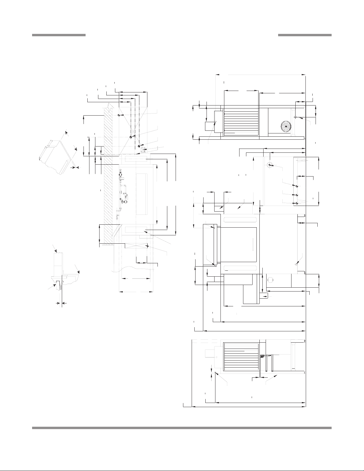
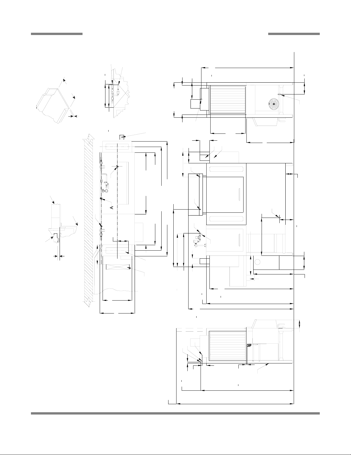
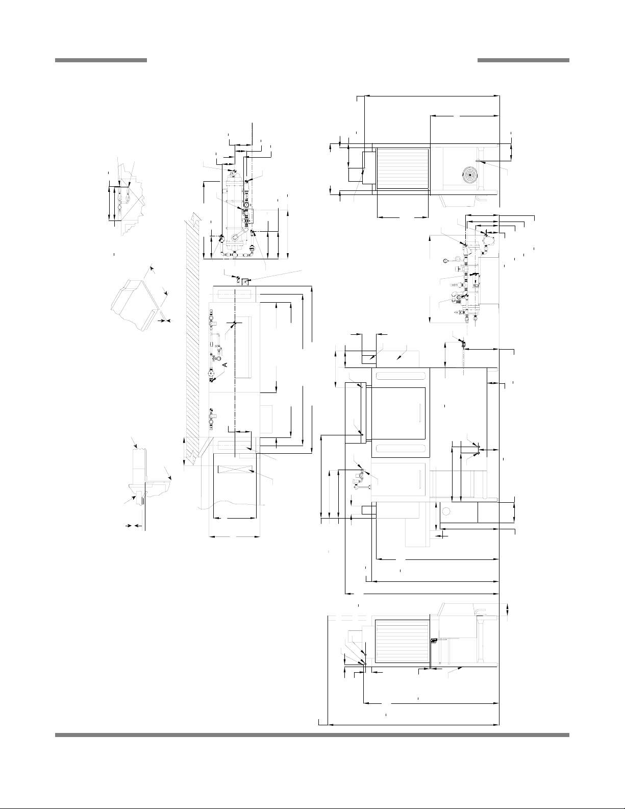
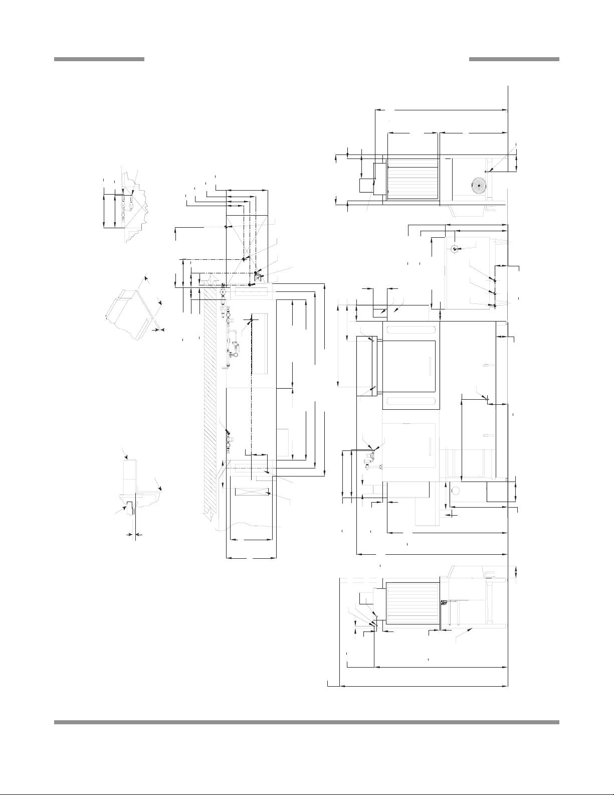
SECTION 1: SPECIFICATION INFORMATION
AJ-44 GAS - RIGHT TO LEFT
Note: Tub Will Accept
Recommended Table Fabrication
[1684mm]
1
12 [307mm]
4
66
[218mm]
1
2
8
25 [635mm]
21" (533 mm)
a Table Flange
Up to 24 7/8"
(632 mm)
Table Turndown
3/4" (19 mm)
Flange 3/4" Max
4 1/2 [114mm]
21 [533mm]
C
25 [635mm]
8 [203mm]
With 3" (76 mm)
Floor Sink Or Drain
B
21 [533mm]
Minimum Drain Line
B
[191mm]
1
[467mm]
1
2
18
8 [206mm]
7 [178mm]
25 [635mm]
D
E
Dish Clearance
34 [864mm]
2
7
B
Right Side
6 [152mm]
Overall
60 [1524mm]
52 [1321mm]
44 [1118mm]
Table to Table
Between Table and
Lip of Machine to
Use Silicone Sealer
Prevent Leakage
Table
6 [152mm]
Tub
[185mm]
1
4
7
14 [357mm]
J
A
C
Front View
7 [178mm]
41 [1042mm]
16 [407mm]
Unit
Drive
10 [254mm]
H
[35mm]
1
4
1
Rack Rail
Rack Rail Height
30 [763mm]
Above Dishtable
1/4" (6mm) - 5/16" (8mm)
[222mm]
4
3
8
[298mm]
4
3
F
G
4" (102 mm) wide x 16" (406 mm)
Shield. Shipped with Cover Plate.
long cutout in Vent Cowl/Splash
[375mm]
4
3
[527mm]
14
4
3
20
4 [102mm]
J
H
36 [914mm]
[672mm]
[794mm]
1
2
1
4
26
31
[1590mm]
1
[1919mm]
1
2
75
2
62
[1530mm]
1
4
60
F
G
29 [737mm]
[163mm]
1
2
6
11
Unit
Drive
A
able bullet feet.
[1692mm]
1
2
1 [25mm]
66
With Doors Open
A - Machine water inlet 3/4" NPT, 110°F-140°F
Hi-temp,140°F Low-temp minimum
Legend to Drawing
Right to Left
C - Drain connection 1-1/2" NPT
B - Electrical connection
gas booster heater.
connection to line on dishmachine.
Connection hose provided by
manufacturer.
be installed to meet local codes by
installing contractor.
F - 3/4" NPT 110°F-140°F Water inlet for
E - Vent cowl standard
D - Vent collar - Optional
G - 3/4" NPT 180°F Water Outlet
H - 3/4" NPT Gas Connection
J - 4" OD Vent pipe connection. Flue to
Note: All vertical dimensions are +/- 1/2" from
84 [2134mm]
floor due to adjust
[15mm]
1
2
Rear of
Machine
8
Left to Right
Drive
Unit
Left Side
Drive
Unit
Front View
Right Side
3/4" (19 mm)
Table Turndown
Flange 3/4" Max
21" (533 mm)
Rack Rail Height
Above Dishtable
1/4" (6mm) - 5/16" (8mm)
Rack Rail
Tub
Table
Use Silicone Sealer
Between Table and
Lip of Machine to
Prevent Leakage
Recommended Table Fa brication
Note: Tub Will Accept
a Table Flange
Up to 24 7/8"
(632 mm)
1
2
[15mm]
84 [2134mm]
75
1
2
[1919mm]
62
1
2
[1590mm]
34 [864mm]
29 [737mm]
6 [152mm]
8
1
2
[218mm]
21 [533mm]
25 [635mm]
12 [307mm]
25 [635mm]
10 [254mm]
7 [178mm]
D
E
A
C
B
18
1
2
[467mm]
4 [102mm]
Table to Table
Overall
With Doors Open
Rear of
Machine
Dish Clearance
14 [356mm]
Minimum
10" High
Table
Backsplash
Scrap
Trough
7
1
2
[190mm]
C
B
Legend
A - Machine water inlet 3/4" NPT 180°F
Hi-temp,140°F Low-temp minimum
B - Electrical connection
C - Drain connection 1-1/2" NPT
D - Vent collar - Optional
E - Vent cowl standard
F - 3/4" NPT Steam connection
G - 3/4" NPT Condensate return
H - Steam electrical connection
J - 1" NPT Steam connection
K - 3/4" Condensate connection
L - 3/4" NPT Incoming 110°F water
connection
M - 3/4" NPT 180°F water to dishmachine.
Note: All vertical dimensions are +/- 1/2"
from floor due to adjustable bullet feet.
60
1
4
[1530mm]
8 [204mm]
7 [178mm]
10 [254mm]
12
1
2
[316mm]
G
F
17
1
2
[445mm]
4" (102 mm) wide x 16" (406 mm)
long cutout in Vent Cowl/Splash
Shield. Shipped with Cover Plate.
Floor Sink Or Drain
With 3" (76 mm)
Minimum Drain Line
25 [637mm]
4 1/2 [114mm]
44 [1118mm]
52 [1321mm]
60 [1524mm]
8 [204mm]
14 [355mm]
Scrap
Trough
Minimum
21 [535mm]
B
1 [25mm]
66
5
8
[1692mm]
65
1
2
[1665mm]
13
5
8
[346mm]
A
6
3
8
[162mm]
11
5
8
[295mm]
15
3
4
[400mm]
16
3
8
[417mm]
43 [1092mm]
11
1
4
[285mm]
13
5
8
[345mm]
23
3
4
[604mm]
38 [966mm]
6
1
4
[159mm]
5
7
8
[148mm]
4
3
8
[110mm]
8
5
8
[218mm]
H
J
L
M
K
L
H
J
M
F
SECTION 1: SPECIFICATION INFORMATION
AJ-44 STEAM - LEFT TO RIGHT
9

Right to Left
Drive
Unit
Left Side
Drive
Unit
Front View
Right Side
3/4" (19 mm)
Table Turndown
Flange 3/4" Max
21" (533 mm)
Rack Rail Height
Above Dishtable
1/4" (6mm) - 5/16" (8mm)
Rack Rail
Tub
Table
Use Silicone Sealer
Between Table and
Lip of Machine to
Prevent Leakage
Recommended Table Fabrication
Note: Tub Will Accept
a Table Flange
Up to 24 7/8"
(632 mm)
1
2
[15mm]
84 [2134mm]
75
1
2
[1919mm]
62
1
2
[1590mm]
34 [864mm]
29 [737mm]
6 [152mm]
8
1
2
[218mm]
21 [533mm]
25 [635mm]
12 [307mm
25 [635mm]
10 [254mm]
7 [178mm]
D
E
A
C
B
18
1
2
[467mm]
4 [102mm]
Table to Table
Overall
With Doors Open
Rear of
Machine
Dish Clearance
7
1
2
[190mm]
C
B
Legend
A - Machine water inlet 3/4" NPT 180°F
Hi-temp,140°F Low-temp minimum
B - Electrical connection
C - Drain connection 1-1/2" NPT
D - Vent collar - Optional
E - Vent cowl standard
F - 3/4" NPT Steam connection
G - 3/4" NPT Condensate return
H - Steam electrical connection
J - 1" NPT Steam connection
K - 3/4" Condensate connection
L - 3/4" NPT Incoming 110°F water
connection
M - 3/4" NPT 180°F water to dishmachine.
Note: All vertical dimensions are +/- 1/2"
from floor due to adjustable bullet feet.
60
1
4
[1530mm]
8 [204mm]
7 [178mm]
10 [254mm]
12
1
2
[316mm]
G
F
17
1
2
[445mm]
4" (102 mm) wide x 16" (406 mm)
long cutout in Vent Cowl/Splash
Shield. Shipped with Cover Plate.
Floor Sink Or Drain
With 3" (76 mm)
Minimum Drain Line
25 [637mm]
4 1/2 [114mm]
44 [1118mm]
52 [1321mm]
60 [1524mm]
8 [204mm]
21 [535mm]
B
1 [25mm]
66
5
8
[1692mm]
65
1
2
[1665mm
13
5
8
[346mm]
A
6
3
8
[162mm]
11
5
8
[295mm]
15
3
4
[400mm]
16
3
8
[417mm]
43 [1092mm]
11
1
4
[285mm]
13
5
8
[345mm]
23
3
4
[604mm]
38 [966mm]
6
1
4
[159mm]
5
7
8
[148mm]
4
3
8
[110mm]
8
5
8
[218mm]
H
J
L
M
K
L
H
J
M
F
SECTION 1: SPECIFICATION INFORMATION
AJ-44 STEAM - RIGHT TO LEFT
10
Drive
Unit
Left Side
Drive
Unit
66
1
2
[1692mm]
3 [79mm]
1
2
[15mm]
84 [2134mm]
75
1
2
[1919mm]
60
1
4
[1530mm]
29 [737mm]
10
1
4
[260mm]
6 [152mm]
10 [254mm]
7 [178mm]
D
E
A
C
C
G
B
4 [102mm]
8 [206mm]
24 [609mm]
41 [1040mm]
F
A
18 [457mm]
27 [687mm]
G
F
23
1
2
[598mm]
Front View
Right Side
34 [864mm]
8
1
2
[217mm]
21 [533mm]
25 [635mm]
12 [307mm]
25 [635mm]
B
Dish Clearance
With Doors Open
Rear of
Machine
14 [356mm]
Minimum
10" High
Table
Backsplash
Scrap
Trough
Base Unit
Overall
Prewash Plan View Section
with Cold Water Thermostat
16
3
4
[425mm]
16
1
4
[415mm]
F
G
6 [152mm]
4" (102 mm) wide x 16" (406 mm)
long cutout in Vent Cowl/Splash
Shield. Shipped with Cover Plate.
Minimum
Scrap
Trough
14 [355mm]
25 [635mm]
21 [533mm]
8 [203mm]
Left to Right
Legend
A - Machine water inlet 3/4" NPT, 180°F
Hi-temp,140°F Low-temp minimum
B - Electrical connection
C - Drain connection 1-1/2" NPT
D - Vent collar - Optional
E - Vent cowl standard
F - Prewash water inlet 3/4" NPT
110°F-140°F
G - Cold water thermostat plumbing
connection 3/4" NPT - Optional
Note: All vertical dimensions are +/- 1/2"
from floor due to adjustable bullet feet.
82 [2086mm]
74 [1883mm]
44 [1121mm]
3/4" (19 mm)
Table Turndown
Flange 3/4" Max
21" (533 mm)
Rack Rail Height
Above Dishtable
1/4" (6mm) - 5/16" (8mm)
Rack Rail
Tub
Table
Use Silicone Sealer
Between Table and
Lip of Machine to
Prevent Leakage
Recommended Table Fabrication
Note: Tub Will Accept
a Table Flange
Up to 24 7/8"
(632 mm)
1 [25mm]
62
1
2
[1590mm]
66
1
4
[1684mm]
Floor Sink Or Drain
With 3" (76 mm)
Minimum Drain Line
B
F
22 [559mm]
Prewash
66 [1679mm]
Table to Table
SECTION 1: SPECIFICATION INFORMATION
AJ-66 ELECTRIC - LEFT TO RIGHT
11
C
Right Side
34 [864mm]
8
1
2
[217mm]
21 [533mm]
25 [635mm]
12 [307mm]
25 [635mm]
B
Dish Clearance
Drive
Unit
Left Side
66
1
2
[1692mm]
3 [79mm]
1
2
[15mm]
84 [2134mm]
A
G
F
With Doors Open
Rear of
Machine
6 [152mm]
Right to Left
Legend
A - Machine water inlet 3/4" NPT, 180°F
Hi-temp,140°F Low-temp minimum
B - Electrical connection
C - Drain connection 1-1/2" NPT
D - Vent collar - Optional
E - Vent cowl standard
F - Prewash water inlet 3/4" NPT
110°F-140°F
G - Cold water thermostat plumbing
connection 3/4" NPT - Optional
Note: All vertical dimensions are +/- 1/2"
from floor due to adjustable bullet feet.
1 [25mm]
Drive
Unit
Front View
75
1
2
[1919mm]
62
1
2
[1590mm]
29 [737mm]
6 [152mm]
10 [254mm]
C
A
B
4 [102mm]
7 [178mm]
D
E
8 [203mm]
42 [1067mm]
41 [1041mm]
24 [610mm]
10
1
4
[260mm]
F
24 [610mm]
G
23
1
2
[599mm]
60
1
4
[1530mm]
66
1
4
[1684mm]
Floor Sink Or Drain
With 3" (76 mm)
Minimum Drain Line
25 [635mm]
4 1/2 [114mm]
8
1
4
[210mm]
21 [533mm]
B
A
F
Table to Table
Overall
Prewash Plan View Section
with Cold Water Thermostat
16
3
4
[425mm]
16
1
4
[415mm]
F
G
82 [2086mm]
74 [1883mm]
66 [1679mm]
3/4" (19 mm)
Table Turndown
Flange 3/4" Max
21" (533 mm)
Rack Rail Height
Above Dishtable
1/4" (6mm) - 5/16" (8mm)
Rack Rail
Tub
Table
Use Silicone Sealer
Between Table and
Lip of Machine to
Prevent Leakage
Recommended Table Fabrication
Note: Tub Will Accept
a Table Flange
Up to 24 7/8"
(632 mm)
4" (102 mm) wide x 16" (406 mm)
long cutout in Vent Cowl/Splash
Shield. Shipped with Cover Plate.
22 [559mm]44 [1121mm]
Base Unit Prewash
SECTION 1: SPECIFICATION INFORMATION
AJ-66 ELECTRIC - RIGHT TO LEFT
12
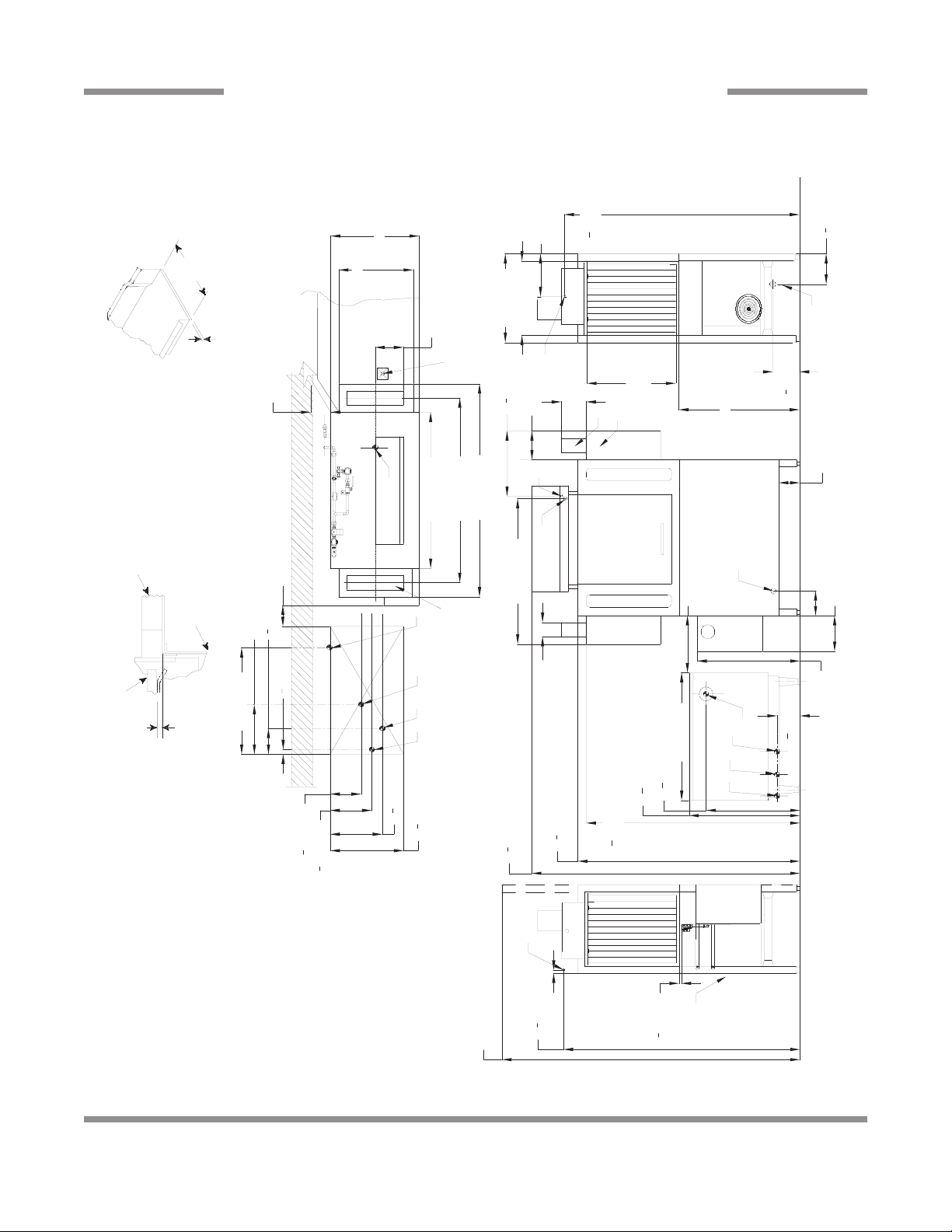
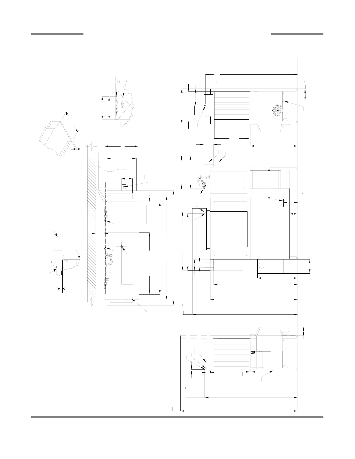
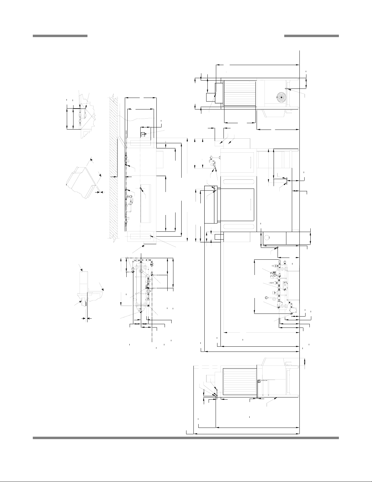
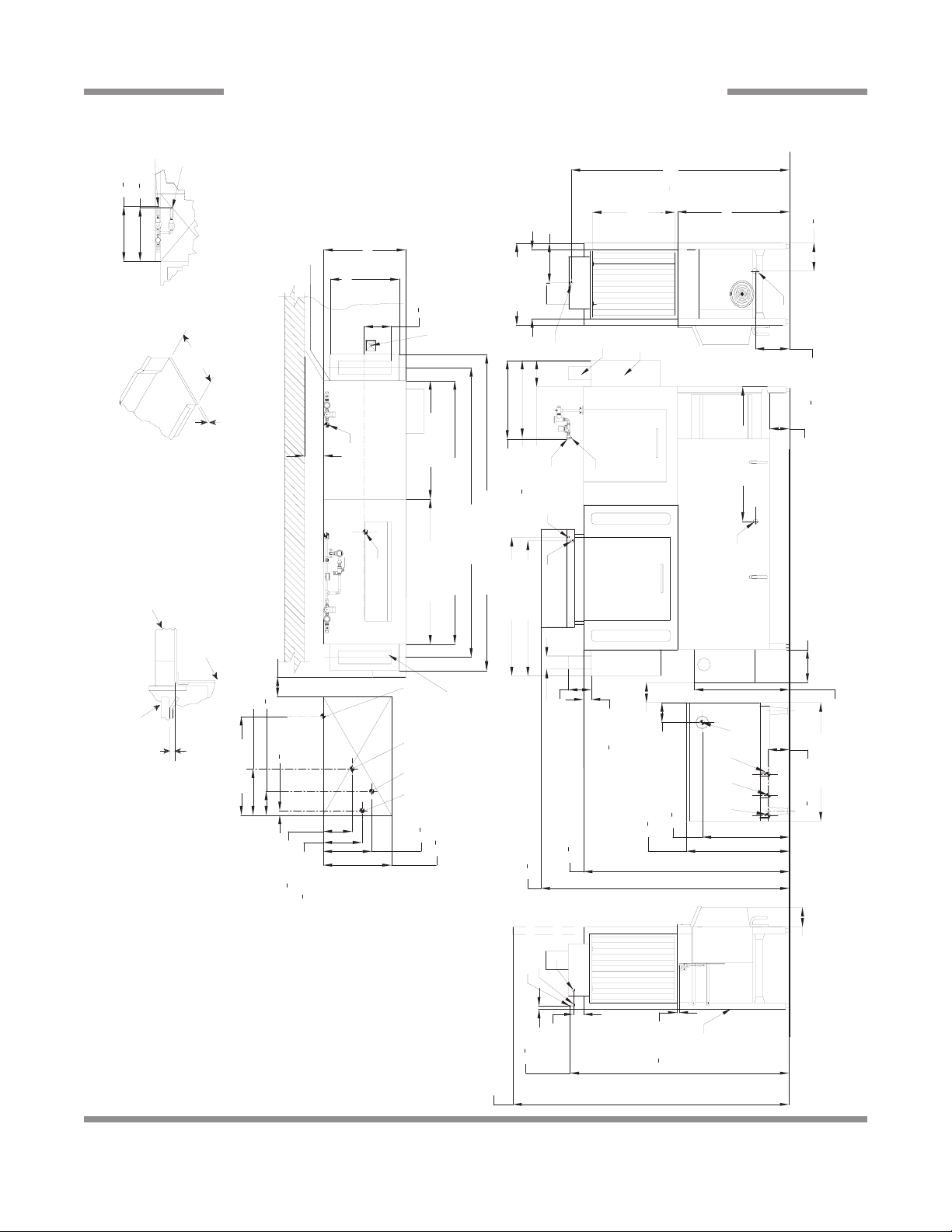
SECTION 1: SPECIFICATION INFORMATION
AJ-66 GAS - LEFT TO RIGHT
K
L
[425mm]
3
4
16
[222mm]
4
3
8
[527mm]
4
3
[375mm]
4
20
3
[298mm]
4
3
14
11
A
1 [25mm]
12 [307mm]
25 [635mm]
Dish Clearance
34 [864mm]
[217mm]
1
2
8
J
with Cold Water Thermostat
Prewash Plan View Section
[415mm]
1
4
16
[185mm]
1
4
7
30 [763mm]
H
25 [635mm]
21 [533mm]
F
B
With 3" (76 mm)
Floor Sink Or Drain
Minimum Drain Line
G
C
Right Side
J
21" (533 mm)
[35mm]
[363mm]
1
4
1
4
1
6 [154mm]
14
a Table Flange
Up to 24 7/8"
(632 mm)
Table Turndown
3/4" (19 mm)
Flange 3/4" Max
Note: Tub Will Accept
K
8 [203mm]
Table
Between Table and
Lip of Machine to
Use Silicone Sealer
Prevent Leakage
44 [1121mm]22 [559mm]
Base Unit
Overall
Table to Table
74 [1883mm]
82 [2086mm]
66 [1679mm]
Prewash
8 [206mm]
18 [457mm]
7 [178mm]
B
A
[795mm]
[673mm]
1
4
1
2
31
26
36 [914mm]
D
E
6 [152mm]
H
G F
1
[165mm]
2
6
6 [152mm]
C
27 [687mm]
K
14 [356mm]
Tub
Minimum
14 [355mm]
Scrap
Trough
L
Rack Rail
Minimum
Unit
Drive
Front View
10 [254mm]
21 [533mm]
[61mm]
1
2
Above Dishtable
Recommended Table Fabrication
Rack Rail Height
25 [635mm]
4" (102 mm) wide x 16" (406 mm)
Shield. Shipped with Cover Plate.
long cutout in Vent Cowl/Splash
1/4" (6mm) - 5/16" (8mm)
110°F-140°F
[598mm]
1
2
23
41 [1040mm]
2
4 [102mm]
24 [609mm]
[1919mm]
1
2
75
Table
Backsplash
10" High
[1530mm]
1
4
60
Scrap
Trough
29 [737mm]
Legend
Left to Right
Water inlet for
stat plumbing
110°F-140°F
ld water thermo
A - Machine water inlet 3/4" NPT,
Hi-temp,140°F Low-temp minimum
C - Drain connection 1-1/2" NPT
B - Electrical connection
gas booster heater.
connection to line on dishmachine.
F - 3/4" NPT 1
D - Vent collar - Optional
E - Vent cowl standard
Connection hose provided by
G - 3/4" NPT 180°F Water Outlet
be installed to meet local codes by
manufacturer.
installing contractor.
H - 3/4" NPT Gas Connection
J - 4" OD Vent pipe connection. Flue to
K - Prewash water inlet 3/4" NPT
connection 3/4" NPT - Optional
110°F-140°F
L - Co
floor due to adjustable bullet feet.
Note: All vertical dimensions are +/- 1/2" f rom
L
K
[105mm]
1
4
A
4
[15mm]
1
3 [79mm]
2
h Doors Open
84 [2134mm]
Unit
Drive
6 [152mm]
Left Side
Rear of
Machine
13
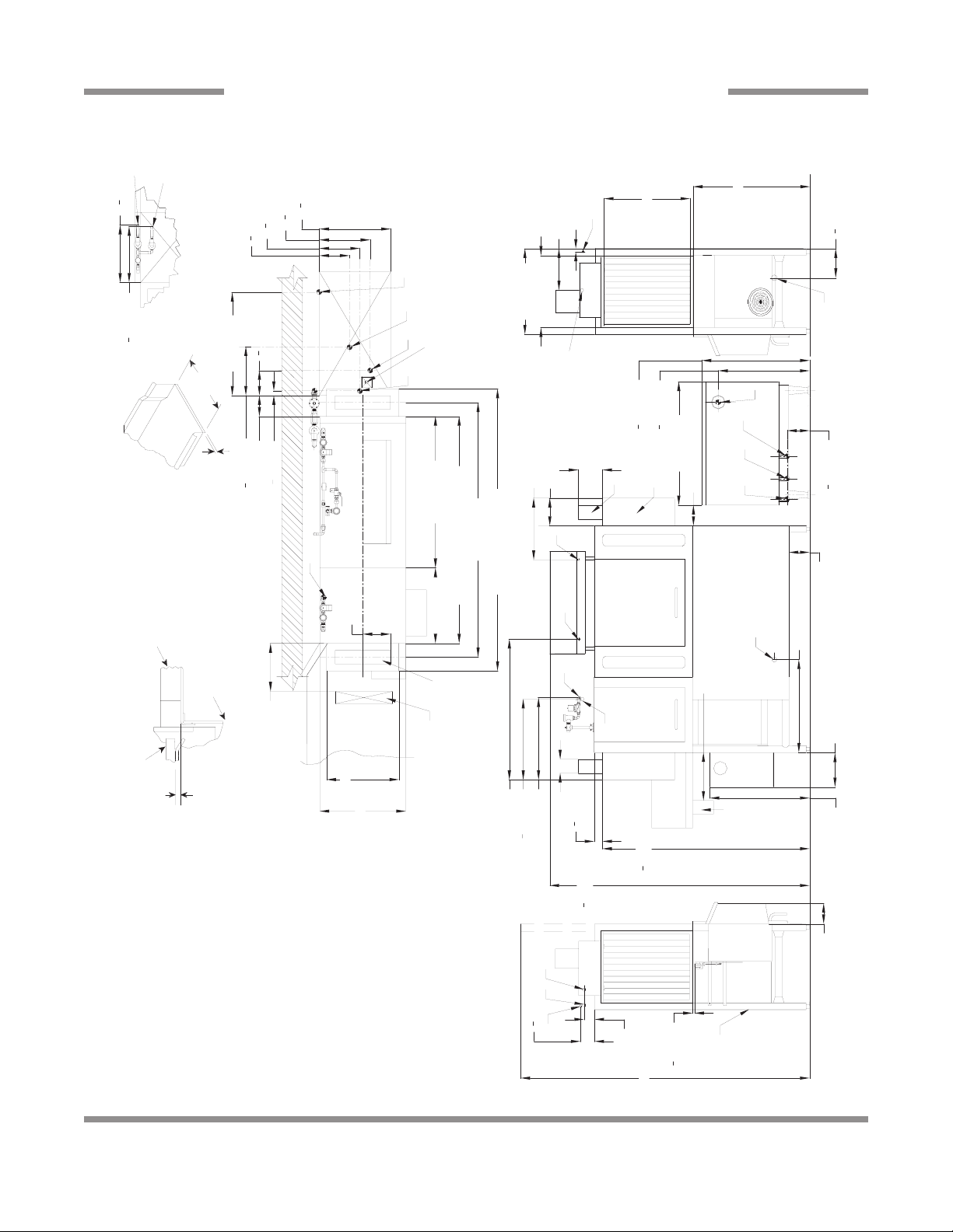
SECTION 1: SPECIFICATION INFORMATION
AJ-66 GAS - RIGHT TO LEFT
[1684mm]
1
12 [307mm]
4
66
[217mm]
1
2
8
F
[425mm]
[415mm]
3
4
1
4
16
16
with Cold Water Thermostat
Prewash Plan View Section
25 [635mm]
21 [533mm]
K
[210mm]
1
4
8
With 3" (76 mm)
Floor Sink Or Drain
22 [559mm]44 [1121mm]
21" (533 mm)
4 1/2 [114mm]
Table to Table
B
Base Unit Prewash
66 [1679mm]
a Table Flange
Up to 24 7/8"
(632 mm)
Table Turndown
3/4" (19 mm)
Flange 3/4" Max
Note: Tub Will Accept
25 [635mm]
21 [533mm]
B
Minimum Drain Line
7 [178mm]
[599mm]
1
2
24 [610mm]
23
25 [635mm]
D
E
Dish Clearance
34 [864mm]
C
B
K
Overall
74 [1883mm]
L
A
24 [610mm]
82 [2086mm]
42 [1067mm]
41 [1041mm]
16 [407mm]
C
Right Side
[260mm]
1
4
10
6 [152mm]
Front View
10 [254mm]
6 [152mm]
Unit
[185mm]
1
4
7
14 [357mm]
Table
Between Table and
Lip of Machine to
Prevent Leakage
Use Silicone Sealer
[35mm]
1
4
1
Tub
30 [763mm]
Rack Rail
[222mm]
4
3
8
[298mm]
4
Recommended Table Fabrication
Above Dishtable
Rack Rail Height
3
11
J
4 [102mm]
HG
F
[375mm]
4" (102 mm) wide x 16" (406 mm)
4
3
14
long cutout in Vent Cowl/Splash
[527mm]
4
3
20
8 [203mm]
36 [914mm]
[672mm]
1
2
[794mm]
1
4
26
Shield. Shipped with Cover Plate.
[1590mm]
1
2
62
[1919mm]
1
2
75
31
[1530mm]
1
4
60
Drive
J
H
F
G
29 [737mm]
[163mm]
1
2
6
1/4" (6mm) - 5/16" (8mm)
Unit
L
K
A
[15mm]
1
[1692mm]
3 [79mm]
1
2
1 [25mm]
66
With Doors Open
84 [2134mm]
A - Machine water inlet 3/4" NPT, 110°F-140°F
Hi-temp,140°F Low-temp minimum
Legend
Left to Right
C - Drain connection 1-1/2" NPT
B - Electrical connection
D - Vent collar - Optional
E - Vent cowl standard
connection to line on dishmachine.
Connection hose provided by
manufacturer.
gas booster heater.
F - 3/4" NPT 110°F-140°F Water inlet for
G - 3/4" NPT 180°F Water Outlet
be installed to meet local codes by
installing contractor.
H - 3/4" NPT Gas Connection
J - 4" OD Vent pipe connection. Flue to
connection 3/4" NPT - Optional
110°F-140°F
L - Cold water thermostat plumbing
K - Prewash water inlet 3/4" NPT
floor due to adjustable bullet feet.
Note: All vertical dimensions are +/- 1/2" from
2
Drive
6 [152mm]
Left Side
Rear of
Machine
14
Drive
Unit
Left Side
Drive
Unit
66
1
2
[1692mm]
3 [79mm]
1
2
[15mm]
84 [2134mm]
75
1
2
[1919mm]
60
1
4
[1530mm]
29 [737mm]
24 [610mm]
10
1
4
[260mm]
17
1
2
[445mm]
6 [152mm]
10 [254mm]
7 [178mm]
D
E
A
C
C
O
B
4 [102mm]
8 [206mm]
G
24 [609mm]
41 [1040mm]
N
A
18 [457mm]
27 [687mm]
O
N
23
1
2
[598mm]
Front View
Right Side
34 [864mm]
8
1
2
[217mm]
21 [533mm]
25 [635mm]
12 [307mm]
25 [635mm]
B
Dish Clearance
With Doors Open
Rear of
Machine
14 [356mm]
Minimum
10" High
Table
Backsplash
Scrap
Trough
Table to Table
Overall
Prewash Plan View Section
with Cold Water Thermostat
16
3
4
[425mm]
16
1
4
[415mm]
N
O
6 [152mm]
4" (102 mm) wide x 16" (406 mm)
long cutout in Vent Cowl/Splash
Shield. Shipped with Cover Plate.
Minimum
Scrap
Trough
14 [355mm]
Floor Sink Or Drain
With 3" (76 mm)
Minimum Drain Line
25 [635mm]
21 [533mm]
8 [203mm]
82 [2086mm]
74 [1883mm]
66 [1679mm]
3/4" (19 mm)
Table Turndown
Flange 3/4" Max
21" (533 mm)
Rack Rail Height
Above Dishtable
1/4" (6mm) - 5/16" (8mm)
Rack Rail
Tub
Table
Use Silicone Sealer
Between Table and
Lip of Machine to
Prevent Leakage
Recommended Table Fabric a tion
Note: Tub Will Accept
a Table Flange
Up to 24 7/8"
(632 mm)
Left to Right
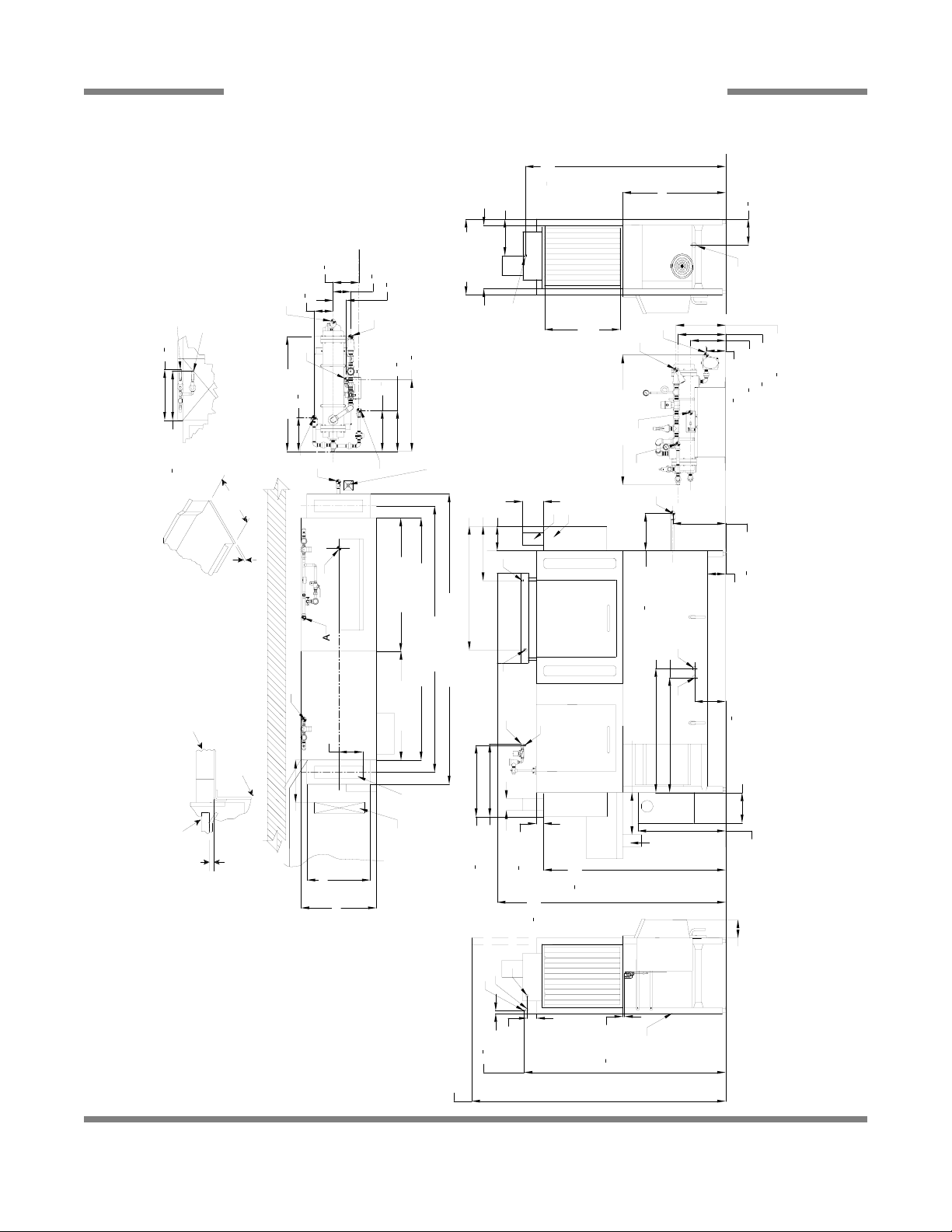
Legend
A - Machine water inlet 3/4" NPT 180°F
Hi-temp,140°F Low-temp minimum
B - Electrical connection
C - Drain connection 1-1/2" NPT
D - Vent collar - Optional
E - Vent cowl standard
F - 3/4" NPT Steam connection
G - 3/4" NPT Condensate return
H - Steam electrical connection
J - 1" NPT Steam connection
K - 3/4" Condensate connection
L - 3/4" NPT Incoming 110°F water
connection
M - 3/4" NPT 180°F water to dishmachine.
N - Prewash water inlet 3/4" NPT
110°F-140°F
O - Cold water thermostat plumbing
connection 3/4" NPT - Optional
Note: All vertical dimensions are +/- 1/2"
from floor due to adjustable bullet feet.
B
38 [966mm]
11
1
4
[285mm]
13
1
2
[345mm]
23
3
4
[604mm]
13
1
2
[345mm]
4
1
4
[110mm]
5
3
4
[148mm]
8
1
2
[218mm]
6
1
4
[159mm]
M
K
L
J
12
1
2
[316mm]
F
16
3
8
[417mm]
15
3
4
[400mm]
11
5
8
[295mm]
6
3
8
[162mm]
M
J
H
L
43 [1092mm]
62
1
2
[1590mm]
1 [25mm]
66
1
4
[1684mm]
F
H
44 [1121mm]22 [559mm]
Base Unit
Prewash
SECTION 1: SPECIFICATION INFORMATION
AJ-66 STEAM - LEFT TO RIGHT
15
C
Right Side
34 [864mm]
8
1
2
[217mm]
21 [533mm]
25 [635mm]
12 [307mm]
25 [635mm]
B
Dish Clearance
Drive
Unit
Left Side
66
1
2
[1692mm]
3 [79mm]
1
2
[15mm]
84 [2134mm]
A
G
F
With Doors Open
Rear of
Machine
6 [152mm]
Right to Left
Legend
A - Machine water inlet 3/4" NPT, 180°F
Hi-temp,140°F Low-temp minimum
B - Electrical connection
C - Drain connection 1-1/2" NPT
D - Vent collar - Optional
E - Vent cowl standard
F - Prewash water inlet 3/4" NPT
110°F-140°F
G - Cold water thermostat plumbing
connection 3/4" NPT - Opti onal
H - Steam electrical connection
J - 1" NPT Steam connection
K - 3/4" Condensate connection
L - 3/4" NPT Incoming 110°F water
connection
M - 3/4" NPT 180°F water to dishmachine.
Note: All vertical dimensions are +/- 1/2"
from floor due to adjustable bullet feet.
1 [25mm]
Drive
Unit
Front View
75
1
2
[1919mm]
62
1
2
[1590mm]
29 [737mm]
6 [152mm]
10 [254mm]
C
A
B
4 [102mm]
7 [178mm]
D
E
8 [203mm]
42 [1067mm]
41 [1041mm]
24 [610mm]
10
1
4
[260mm]
F
24 [610mm]
G
23
1
2
[599mm]
60
1
4
[1530mm]
66
1
4
[1684mm]
Floor Sink Or Drain
With 3" (76 mm)
Minimum Drain Line
25 [635mm]
4 1/2 [114mm]
8
1
4
[210mm]
21 [533mm]
B
A
F
Table to Table
Overall
Prewash Plan View Section
with Cold Water Thermostat
16
3
4
[425mm]
16
1
4
[415mm]
F
G
82 [2086mm]
74 [1883mm]
66 [1679mm]
3/4" (19 mm)
Table Turndown
Flange 3/4" Max
21" (533 mm)
Rack Rail Height
Above Dishtable
1/4" (6mm) - 5/16" (8mm)
Rack Rail
Tub
Table
Use Silicone Sealer
Between Table and
Lip of Machine to
Prevent Leakage
Recommended Table Fabrication
Note: Tub Will Accept
a Table Flange
Up to 24 7/8"
(632 mm)
4" (102 mm) wide x 16" (406 mm)
long cutout in Vent Cowl/Splash
Shield. Shipped with Cover Plate.
22 [559mm]44 [1121mm]
Base Unit Prewash
12
1
2
[316mm]
F
H
J
L
M
K
L
H
J
M
F
38 [966mm]
11
1
4
[285mm]
13
1
2
[345mm]
23
3
4
[604mm]
4
1
4
[110mm]
5
3
4
[148mm]
8
1
2
[218mm]
6
1
4
[159mm]
43 [1092mm]
17
1
2
[445mm]
6
1
2
[162mm]
11
1
2
[295mm]
15
3
4
[400mm]
16
1
2
[417mm]
G
27 [686mm]
SECTION 1: SPECIFICATION INFORMATION
AJ-66 STEAM - RIGHT TO LEFT
16
Drive
Unit
Left Side
66
1
2
[1692mm]
3 [79mm]
1
2
[15mm]
84 [2134mm]
A
C
G
F
Right Side
34 [864mm]
8
1
2
[217mm]
21 [533mm]
25 [635mm]
12 [307mm]
25 [635mm]
B
Dish Clearance
With Doors Open
Rear of
Machine
Base Unit
Overall
Prewash Plan View Section
with Cold Water Thermostat
16
3
4
[425mm]
16
1
4
[415mm]
F
G
6 [152mm]
4" (102 mm) wide x 16" (406 mm)
long cutout in Vent Cowl/Splash
Shield. Shipped with Cover Plate.
Minimum
Scrap
Trough
14 [355mm]
25 [635mm]
21 [533mm]
8 [203mm]
Left to Right
Legend
A - Machine water inlet 3/4" NPT, 180°F
Hi-temp,140°F Low-temp minimum
B - Electrical connection
C - Drain connection 1-1/2" NPT
D - Vent collar - Optional
E - Vent cowl standard
F - Prewash water inlet 3/4" NPT
110°F-140°F
G - Cold water thermostat plumbing
connection 3/4" NPT - Optional
Note: All vertical dimensions are +/- 1/2"
from floor due to adjustable bullet feet.
88 [2238mm]
44 [1121mm]
3/4" (19 mm)
Table Turndown
Flange 3/4" Max
21" (533 mm)
Rack Rail Height
Above Dishtable
1/4" (6mm) - 5/16" (8mm)
Rack Rail
Tub
Table
Use Silicone Sealer
Between Table and
Lip of Machine to
Prevent Leakage
Recommended Table Fabrication
Note: Tub Will Accept
a Table Flange
Up to 24 7/8"
(632 mm)
1 [25mm]
66
1
4
[1684mm]
Floor Sink Or Drain
With 3" (76 mm)
Minimum Drain Line
B
F
36 [914mm]
Prewash
Table to Table
96 [2441mm]
80 [2035mm]
Front View
75
1
2
[1919mm]
60
1
4
[1530mm]
2
1
2
[61mm]
29 [737mm]
38 [966mm]
10
1
4
[260mm]
6 [152mm]
10 [254mm]
7 [178mm]
D
E
C
A
B
41 [1039mm]
8 [206mm]
G
24 [610mm]
23
1
2
[600mm]
G
18 [457mm]
41 [1043mm]
4 [102mm]
Drive
Unit
F
14 [356mm]
Minimum
10" High
Table
Backsplash
Scrap
Trough
SECTION 1: SPECIFICATION INFORMATION
AJ-80 ELECTRIC - LEFT TO RIGHT
17
C
Right Side
34 [864mm]
8
1
2
[217mm]
21 [533mm]
25 [635mm]
12 [307mm]
25 [635mm]
B
Dish Clearance
Drive
Unit
Left Side
66
1
2
[1692mm]
3 [79mm]
1
2
[15mm]
84 [2134mm]
A
G
F
With Doors Open
Rear of
Machine
6 [152mm]
Right to Left
Legend
A - Machine water inlet 3/4" NPT, 180°F
Hi-temp,140°F Low-temp minimum
B - Electrical connection
C - Drain connection 1-1/2" NPT
D - Vent collar - Optional
E - Vent cowl standard
F - Prewash water inlet 3/4" NPT
110°F-140°F
G - Cold water thermostat plumbing
connection 3/4" NPT - Optional
Note: All vertical dimensions are +/- 1/2"
from floor due to adjustable bullet feet.
1 [25mm]
66
1
4
[1684mm]
Floor Sink Or Drain
With 3" (76 mm)
Minimum Drain Line
25 [635mm]
4 1/2 [114mm]
8
1
4
[210mm]
21 [533mm]
B
A
F
Table to Table
Overall
Prewash Plan View Section
with Cold Water Thermostat
16
3
4
[425mm]
16
1
4
[415mm]
F
G
88 [2238mm]
3/4" (19 mm)
Table Turndown
Flange 3/4" Max
21" (533 mm)
Rack Rail Height
Above Dishtable
1/4" (6mm) - 5/16" (8mm)
Rack Rail
Tub
Table
Use Silicone Sealer
Between Table and
Lip of Machine to
Prevent Leakage
Recommended Table Fabrication Note: Tub Will Accept
a Table Flange
Up to 24 7/8"
(632 mm)
4" (102 mm) wide x 16" (406 mm)
long cutout in Vent Cowl/Splash
Shield. Shipped with Cover Plate.
44 [1121mm]
Base Unit
Prewash
36 [914mm]
96 [2441mm]
80 [2035mm]
Front View
75
1
2
[1921mm]
62
1
2
[1590mm]
29 [734mm]
6 [152mm]
10 [254mm]
A
B
41 [1042mm]
C
23
1
2
[598mm]
24 [611mm]
G
42 [1069mm]
4 [102mm]
Drive
Unit
F
D
E
8 [203mm]
41 [1041mm]
7 [178mm]
60
1
4
[1529mm]
SECTION 1: SPECIFICATION INFORMATION
AJ-80 ELECTRIC - RIGHT TO LEFT
18
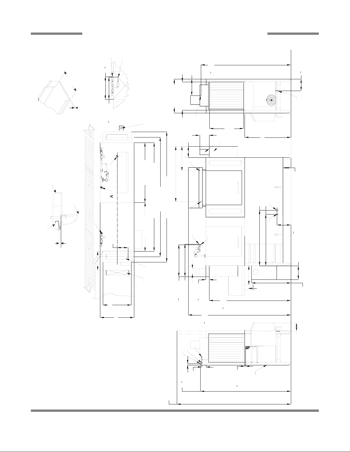
SECTION 1: SPECIFICATION INFORMATION
AJ-80 GAS - LEFT TO RIGHT
[1684mm]
1
4
66
[217mm]
C
1
2
12 [307mm]
K
[425mm]
L
[415mm]
4
3
1
4
16
16
3
[527mm]
3
4
[375mm]
4
20
3
[298mm]
4
3
14
[222mm]
11
4
8
J
25 [635mm]
21 [533mm]
B
25 [635mm]
Dish Clearance
34 [864mm]
8
Right Side
Note: Tub Will Accept
Recommended Table Fabrication
H
with Cold Water Thermostat
Prewash Plan View Section
[185mm]
1
4
7
30 [763mm]
21" (533 mm)
F
With 3" (76 mm)
Minimum Drain Line
Floor Sink Or Drain
G
41 [1039mm]
8 [206mm]
18 [457mm]
[795mm]
[673mm]
1
4
1
2
31
26
D
7 [178mm]
36 [914mm]
E
6 [152mm]
J
H
G F
[165mm]
1
2
6
B
[35mm]
[363mm]
1
4
1
4
1
6 [154mm]
14
a Table Flange
Up to 24 7/8"
(632 mm)
Table Turndown
3/4" (19 mm)
Flange 3/4" Max
Table
Use Silicone Sealer
Between Table and
Lip of Machine to
Prevent Leakage
Tub
Rack Rail
Above Dishtable
Rack Rail Height
1/4" (6mm) - 5/16" (8mm)
B
Base Unit
44 [1121mm]
Table to Table
Overall
C
88 [2238mm]
80 [2035mm]
K
36 [914mm]
96 [2441mm]
Prewash
A
K
L
8 [203mm]
41 [1043mm]
Minimum
14 [356mm]
6 [152mm]
Front View
[260mm]
1
4
10
10 [254mm]
Unit
Drive
Minimum
14 [355mm]
21 [533mm]
25 [635mm]
Scrap
Trough
4" (102 mm) wide x 16" (406 mm)
long cutout in Vent Cowl/Splash
[600mm]
1
Shield. Shipped with Cover Plate.
[61mm]
2
1
2
24 [610mm]
2
4 [102mm]
23
[1919mm]
1
2
75
Table
10" High
[1530mm]
1
4
60
Scrap
Backsplash
Trough
29 [737mm]
Unit
L
K
A
Drive
6 [152mm]
Left Side
at plumbing
[1692mm]
1
2
66
3 [79mm]
3/4" NPT - Optional
A - Machine water inlet 3/4" NPT, 110°F-140°F
Hi-temp,140°F Low-temp minimum
Legend
Left to Right
C - Drain connection 1-1/2" NPT
B - Electrical connection
gas booster heater.
connection to line on dishmachine.
Connection hose provided by
manufacturer.
be installed to meet local codes by
installing contractor.
F - 3/4" NPT110°F-140°F Water inlet for
D - Vent collar - Optional
E - Vent cowl standard
H - 3/4" NPT Gas Connection
G - 3/4" NPT 180°F Water Outlet
J - 4" OD Vent pipe connection. Flue to
connection
110°F-140°F
K - Prewash water inlet 3/4" NPT
L - Cold water thermost
floor due to adjustable bullet feet.
Note: All vertical dimensions are +/- 1/2" from
1 [25mm]
With Doors Open
84 [2134mm]
[15mm]
1
2
Rear of
Machine
19
SECTION 1: SPECIFICATION INFORMATION
AJ-80 GAS - RIGHT TO LEFT
K
L
[425mm]
[415mm]
4
3
1
4
16
16
12 [307mm]
25 [635mm]
with Cold Water Thermostat
Prewash Plan View Section
21 [533mm]
[210mm]
1
4
8
With 3" (76 mm)
Minimum Drain Line
Floor Sink Or Drain
25 [635mm]
21 [533mm]
D
B
[1684mm]
1
4
66
[217mm]
1
2
25 [635mm]
Dish Clearance
34 [864mm]
8
C
Right Side
E
21" (533 mm)
[264mm]
1
4
10
L
36 [914mm]
a Table Flange
Up to 24 7/8"
(632 mm)
Table Turndown
3/4" (19 mm)
Flange 3/4" Max
Note: Tub Will Accept
4 1/2 [114mm]
Table to Table
Overall
K
[598mm]
1
2
8 [203mm]
24 [611mm]
23
B
L
41 [1041mm]
6 [152mm]
C
B
Table
Use Silicone Sealer
Between Table and
Lip of Machine to
Prevent Leakage
Tub
Rack Rail
Above Dishtable
Recommended Table Fabrication
Rack Rail Height
6 [152mm]
[185mm]
1
4
7
14 [357mm]
[35mm]
1
4
1
30 [763mm]
J
H
F
G
1/4" (6mm) - 5/16" (8mm)
[375mm]
4
3
14
[222mm]
4
3
8
[298mm]
4
3
11
88 [2238mm]
Base Unit Prewash
96 [2441mm]
80 [2035mm]
44 [1121mm]
4" (102 mm) wide x 16" (406 mm)
Shield. Shipped with Cover Plate.
long cutout in Vent Cowl/Splash
[527mm]
4
3
20
A
42 [1069mm]
41 [1042mm]
10 [254mm]
Front View
Unit
Drive
7 [178mm]
4 [102mm]
[61mm]
1
2
2
6 [155mm]
6 [152mm]
[673mm]
1
2
[797mm]
1
4
26
[1592mm]
3
4
62
[1921mm]
1
2
75
31
J
H
F
G
29 [735mm]
36 [914mm]
[165mm]
1
2
6
A - Machine water inlet 3/4" NPT, 110°F-140°F
Hi-temp,140°F Low-temp minimum
Legend
Right to Left
C - Drain connection 1-1/2" NPT
B - Electrical connection
D - Vent collar - Optional
Unit
L
K
A
[1692mm]
1
2
66
3 [79mm]
1 [25mm]
Cold water thermostat plumbing
connection to line on dishmachine.
gas booster heater.
Connection hose provided by
manufacturer.
F - 3/4" NPT 110°F-140°F Water inlet for
E - Vent cowl standard
G - 3/4" NPT 180°F Water Outlet
H - 3/4" NPT Gas Connection
J - 4" OD Vent pipe connection. Flue to
110°F-140°F
be installed to meet local codes by
installing contractor.
connection 3/4" NPT - Optional
L -
K - Prewash water inlet 3/4" NPT
floor due to adjustable bullet feet.
Note: All vertical dimensions are +/- 1/2" from
With Doors Open
84 [2134mm]
[15mm]
1
2
Drive
6 [152mm]
Left Side
Rear of
Machine
20
Drive
Unit
Left Side
66
1
2
[1692mm]
3 [79mm]
1
2
[15mm]
84 [2134mm]
A
C
O
N
Right Side
34 [864mm]
8
1
2
[217mm]
21 [533mm]
25 [635mm]
12 [307mm]
25 [635mm]
B
Dish Clearance
With Doors Open
Rear of
Machine
Base Unit
Overall
Prewash Plan View Section
with Cold Water Thermostat
16
3
4
[425mm]
16
1
4
[415mm]
N
O
6 [152mm]
4" (102 mm) wide x 16" (406 mm)
long cutout in Vent Cowl/Splash
Shield. Shipped with Cover Plate.
Minimum
Scrap
Trough
14 [355mm]
25 [635mm]
21 [533mm]
8 [203mm]
Left to Right
88 [2238mm]
44 [1121mm]
3/4" (19 mm)
Table Turndown
Flange 3/4" Max
21" (533 mm)
Rack Rail Height
Above Dishtable
1/4" (6mm) - 5/16" (8mm)
Rack Rail
Tub
Table
Use Silicone Sealer
Between Table and
Lip of Machine to
Prevent Leakage
Recommended Table Fabrication
Note: Tub Will Accept
a Table Flange
Up to 24 7/8"
(632 mm)
1 [25mm]
66
1
4
[1684mm]
B
N
36 [914mm]
Prewash
Table to Table
96 [2441mm]
80 [2035mm]
Front View
75
1
2
[1919mm]
60
1
4
[1530mm]
2
1
2
[61mm]
29 [737mm]
38 [966mm]
10
1
4
[260mm]
6 [152mm]
10 [254mm]
7 [178mm]
D
E
C
A
B
41 [1039mm]
8 [206mm]
G
24 [610mm]
23
1
2
[600mm]
O
18 [457mm]
41 [1043mm]
4 [102mm]
Drive
Unit
N
14 [356mm]
Minimum
10" High
Table
Backsplash
Scrap
Trough
Floor Sink Or Drain
With 3" (76 mm)
Minimum Drain Line
38 [966mm]
11
1
4
[285mm]
13
1
2
[345mm]
23
3
4
[604mm]
13
1
2
[345mm]
4
1
4
[110mm]
5
3
4
[148mm]
8
1
2
[218mm]
6
1
4
[159mm]
M
K
L
J
F
H
17
1
2
[445mm]
12
1
2
[316mm]
F
16
3
8
[417mm]
15
3
4
[400mm]
11
5
8
[295mm]
6
3
8
[162mm]
M
J
H
L
43 [1092mm]
Legend
A - Machine water inlet 3/4" NPT 180°F
Hi-temp,140°F Low-temp minimum
B - Electrical connection
C - Drain connection 1-1/2" NPT
D - Vent collar - Optional
E - Vent cowl standard
F - 3/4" NPT Steam connection
G - 3/4" NPT Condensate return
H - Steam electrical connection
J - 1" NPT Steam connection
K - 3/4" Condensate connection
L - 3/4" NPT Incoming 110°F water
connection
M - 3/4" NPT 180°F water to dishmachine.
N - Prewash water inlet 3/4" NPT
110°F-140°F
O - Cold water thermostat plumbing
connection 3/4" NPT - Optional
Note: All vertical dimensions are +/- 1/2"
from floor due to adjustable bullet feet.
SECTION 1: SPECIFICATION INFORMATION
AJ-80 STEAM - LEFT TO RIGHT
21
C
34 [864mm]
8
1
2
[217mm]
21 [533mm]
25 [635mm]
12 [307mm]
25 [635mm]
B
Dish Clearance
Drive
Unit
Left Side
66
1
2
[1692mm]
3 [79mm]
1
2
[15mm]
84 [2134mm]
A
G
F
With Doors Open
Rear of
Machine
6 [152mm]
Right to Left
1 [25mm]
66
1
4
[1684mm]
Floor Sink Or Drain
With 3" (76 mm)
Minimum Drain Line
25 [635mm]
4 1/2 [114mm]
8
1
4
[210mm]
21 [533mm]
B
A
F
Table to Table
Overall
Prewash Plan View Section
with Cold Water Thermostat
16
3
4
[425mm]
16
1
4
[415mm]
F
G
88 [2238mm]
3/4" (19 mm)
Table Turndown
Flange 3/4" Max
21" (533 mm)
Rack Rail Height
Above Dishtable
1/4" (6mm) - 5/16" (8mm)
Rack Rail
Tub
Table
Use Silicone Sealer
Between Table and
Lip of Machine to
Prevent Leakage
Recommended Table Fabrication
Note: Tub Will Accept
a Table Flange
Up to 24 7/8"
(632 mm)
4" (102 mm) wide x 16" (406 mm)
long cutout in Vent Cowl/Splash
Shield. Shipped with Cover Plate.
44 [1121mm]
Base Unit Prewash
36 [914mm]
96 [2441mm]
80 [2035mm]
Front View
75
1
2
[1921mm]
60
1
4
[1529mm]
62
3
4
[1592mm]
29 [735mm]
10
1
4
[260mm]
6 [152mm]
10 [254mm]
G
A
B
41 [1042mm]
C
23
1
2
[598mm]
24 [611mm]
G
42 [1069mm]
4 [102mm]
Drive
Unit
F
D
E
8 [203mm]
41 [1041mm]
38 [965mm]
7 [178mm]
Right Side
Legend
A - Machine water inlet 3/4" NPT, 180°F
Hi-temp,140°F Low-temp minimum
B - Electrical connection
C - Drain connection 1-1/2" NPT
D - Vent collar - Optional
E - Vent cowl standard
F - Prewash water inlet 3/4" NPT
110°F-140°F
G - Cold water thermostat plumbing
connection 3/4" NPT - Optional
H - Steam electrical connection
J - 1" NPT Steam connection
K - 3/4" Condensate connection
L - 3/4" NPT Incoming 110°F water
connection
M - 3/4" NPT 180°F water to dishmachine.
Note: All vertical dimensions are +/- 1/2"
from floor due to adjusta ble bullet feet.
H
J
L
M
K
F
38 [966mm]
11
1
4
[285mm]
13
1
2
[345mm]
23
3
4
[604mm]
4
1
4
[110mm]
5
3
4
[148mm]
8
1
2
[218mm]
6
1
4
[159mm]
12
1
2
[316mm]
F
L
H
J
M
43 [1092mm]
17
1
2
[445mm]
6
1
2
[162mm]
11
1
2
[295mm]
15
3
4
[400mm]
16
1
2
[417mm]
SECTION 1: SPECIFICATION INFORMATION
AJ-80 STEAM - RIGHT TO LEFT
22
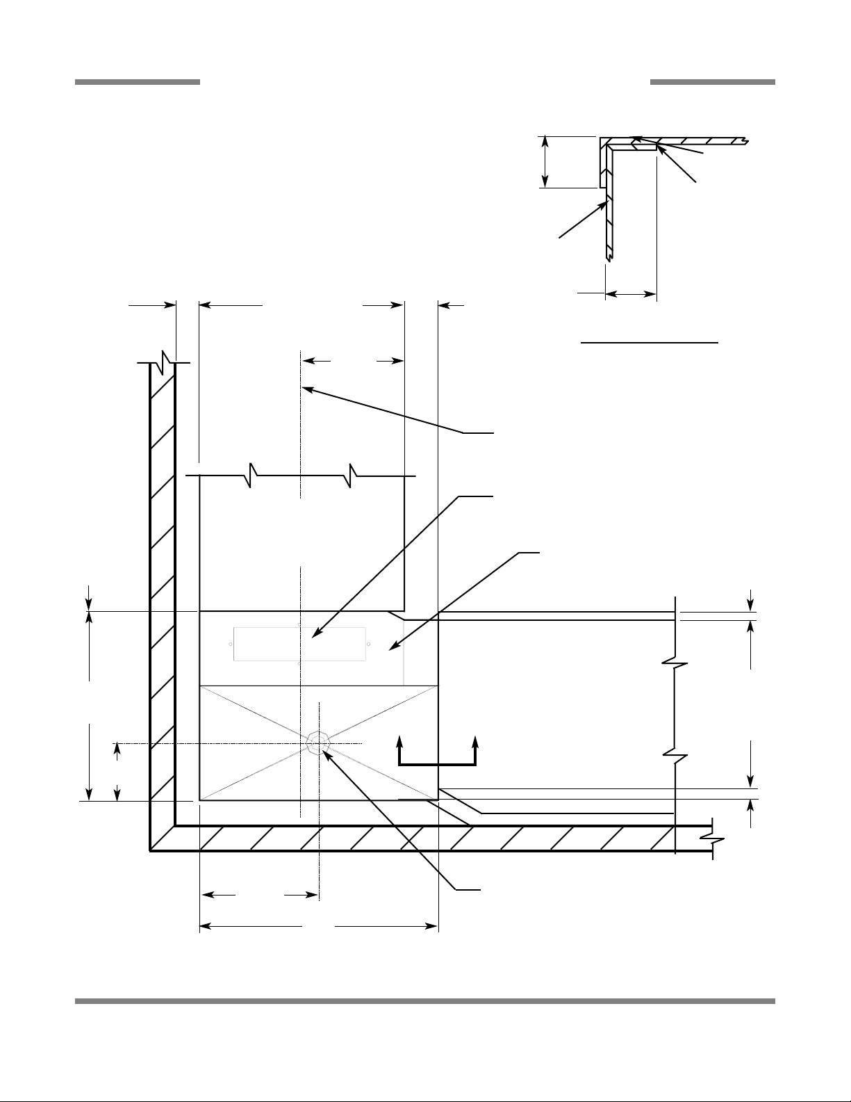
SECTION 1: SPECIFICATION INFORMATION
SIDE LOADER (LEFT TO RIGHT) DIMENSIONS
23
NOTE: ALL DIMENSIONS ARE TYPICAL.
23”**
CONVEYOR
DISHWASHER
LENGTH
8”*
4 1/2”
MINIMUM
25”
DISHWASHER
5”
12 1/2”
14 1/2”
29”
1 1/2” TABLE
ROLL
20 3/4”
OPENING
1”
A A
1/2”
MINIMUM
1/2”
DISHTABLE
USE SILICONE
BETWEEN
TABLE AND LIP
OF SIDE
LOADER TO
PREVENT LEAKAGE.
WALL OF SIDE
LOADER
SECTION “A-A”
CENTER-LINE
DISHMACHINE
SPLASH SHIELD
VENT CONNECTION
OPENING
1 1/2” DRAIN. CONNECTED
TO DISHMACHINE DRAIN
LINE
CONVEYOR
DISHMACHINE
* - 15” on 30” model
** - 30” on 30 “ model
 Loading...