

Jackson 999-156, 999-157, 999-158, 999-159 user manual

READ THESE INSTRUCTIONS THOROUGHLY!
Follow the instructions STEP-BY-STEP, and your
installation will be trouble free. If in doubt, CALL
1-888-888-4079. We suggest that as you proceed through the installation, you should read a
few steps ahead in the instructions so you are
certain to catch all notes and warnings.
ATTENTION SUPERCHARGER INSTALLER!
Before proceeding with the installation, it is
important to know that to validate the 2 year,
100K warranty on your new J/R supercharger,
you must completely fill out the Moss Motors /
Jackson Racing warranty card that comes in
every kit, including serial number which is on a
small white ‘bar code’ label on the body of the
supercharger. Write down all of the numbers
which appear on that label in the appropriate
space on the warranty card. Be certain to do this
now because once your supercharger is
installed, it may be almost impossible to retrieve
that serial number.
SPECIAL NOTE: Jackson Racing Supercharger
Systems are designed to be installed by individuals with good mechanical sense and with the
proper tools. Use your discretion--if you are not a
competent mechanic, do not attempt this installation.
TOOLS REQUIRED: Most of these tools are
available at your local hardware or auto parts
stores.
17mm, 14mm, 13mm, 12mm, 10mm & 8mm
sockets
Deep sockets (14mm or 9/16”, 10mm)
Phillips and Standard screwdriver
Multi-purpose pliers
10mm, 12mm, and 17mm open end wrench
Timing light
A shop manual is useful.
WARNING: Once the installation is complete,
CHECK AND RECHECK ALL fuel system connections for possible leaks before operating the
vehicle. 91-octane gasoline (or higher) is
required when running a supercharger.
During this installation process, you will reuse
some parts or hardware and not reinstall others.
It is recommended that you make space for
those that you will reuse, and a separate space
for those that you will not reinstall. In addition,
you should save the parts that will not get reused
in case you ever have reason to convert the
engine back to stock.
Enclosed is a set of labels that we suggest you
use to label the electrical connectors that you will
be unplugging.
Installation Instructions
SUPERCHARGER
with PowerCard
‘90-’93 Mazda Miata
Part# 999-156, 999-157, 999-158, 999-159
440 Rutherford St. P.O. Box 847 Goleta, CA 93117
1-888-888-4079 • FAX 805-692-2523 • www.supercharger.com
999-156 -1- Revised 1/07
1.0 DISASSEMBLY
1.1 With the engine running, raise the hood and
locate the main under hood fuse box by the fender well near the firewall on the passenger side of
the engine compartment. Lift the main fuse box
cover and locate the relay labeled “FUEL INJ”.
While the engine is running, remove the “FUEL
INJ” relay. The engine will stop running. Turn
your ignition key off. Store the “FUEL INJ” relay
in a safe place until you are finished with the
installation. Release the pressure in your fuel
tank by removing your gas cap momentarily and
then re-installing.
1.2 Release the airflow meter harness 7-pin connector by lifting the small wire clip that runs
around the rectangular base of the connector.
Remove the stock air flow meter, air filter box and
intake snorkel. Remove the air flow meter from
the air box. Store the air box, filter, and snorkel
away. Move the air flow meter to a safe place on
a worktable.
1.3 Remove the molded rubber elbow and hard
plastic tube that lead from the throttle body to the
airflow meter. If you have cruise control, you will
also have to remove the vacuum line from the
intake manifold nipple and from the points where
it attaches to the hard plastic intake tube.
Remove the cruise control vacuum line from the
cruise actuator as well and save it for use in step
#4.4 later.
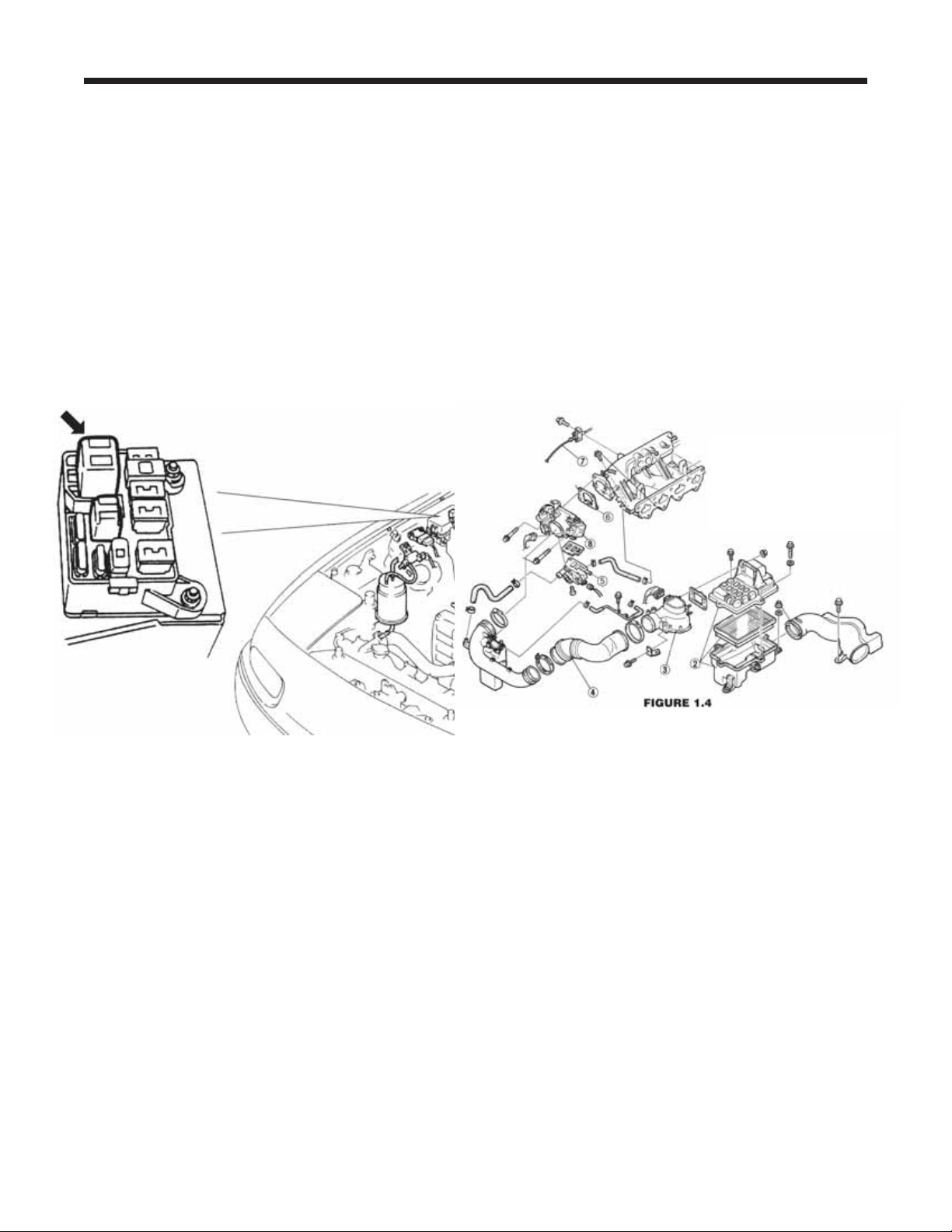
1.4 Remove the chrome crankcase vent pipe that
is attached to the front of the cam cover and the
rubber hose that leads into the cam cover
(Figure 1.4). These can be stored away.
However, find the small restrictor inside the rubber hose that ran from the cam cover to the
chrome tubing. It can be felt as a lump in the
straight section of the hose near the chrome tube
end. Persuade it out by gently clamping the hose
with a pair of pliers just behind the “lump”. Save
this restrictor for step #7.8. Re-install the chrome
bolts that held the tubing in place. Store the
chrome tube and Mazda hoses away.
2.0 THROTTLE BODY
2.1 Remove the throttle body (Figure 1.4) by
releasing the two electrical connectors (one has
a spring wire, one has a plastic lever clip), the
two small coolant hoses on either side of the
lower Idle Control System (ICS) valve, and the
four bolts.
TIP: THE SPRING HOSE CLAMPS FROM
MAZDA ARE BEST REMOVED BY
APPROACHING FROM THE SIDE WITH NEEDLE NOSE PLIERS. GRASP ALL THREE
TANGS AT ONCE AND COMPRESS THEM
TOGETHER. THIS IS EASIER TO DO WITH
THE THROTTLE BODY ALREADY LOOSE
FROM THE INTAKE MANIFOLD.
999-156 -2- Revised 1/07
Supercharger Installation Instructions
2. Stock Air Filter Box
3. Air Flow
4. Stock Plastic / Rubber Cross Over
5. ICS Valve (Idle Air Control)
6. Throttle Body Gasket
7. Throttle Cable
8. Throttle Body
Keep the hose ends above the radiator cap
level to prevent leakage. Release the throttle
cable from the throttle shaft spool. Release the
Throttle Position Switch harness by lifting the
small wire clip that runs around the rectangular
base of the connector. If the throttle body gasket
tears as you remove it, you will need to clean
off the old gasket from both surfaces, the throttle body and the intake manifold. Carefully use a
knife or the backside of a hacksaw blade to
scrape the mounting surfaces clean. DO NOT
SCRATCH OR MAR THE MOUNTING SURFACES IN ANY WAY.
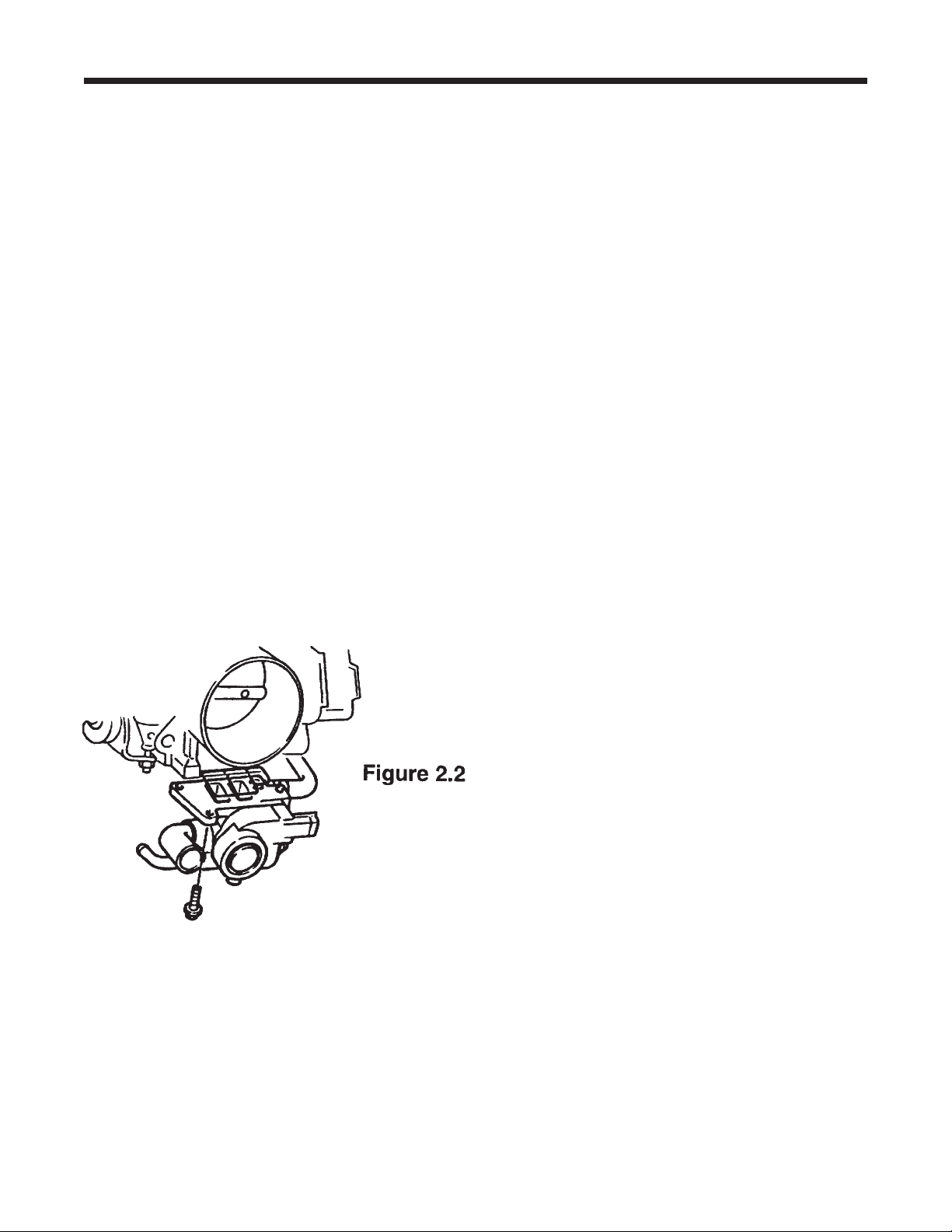
2.2 Moving to a worktable, remove the idle air
control (ICS) valve from the bottom of the throttle body by removing the three Phillips head
screws. Use a good quality screwdriver and be
careful not to strip the Phillips head screws. If
you cannot loosen a screw with the screwdriver,
use a small set of pliers from the side. Carefully
separate the two units making sure not to tear
the rubber gland gasket. The rubber gland gasket will want to stay with the Mazda throttle
body carefully pick it out with a flat blade screwdriver and save it for the next step.
2.3 Take the Idle Air Manifold (dummy throttle
body) from your supercharger kit and install the
Mazda idle air control valve (ICS) from step 2.2
in the appropriate place. Use the rubber gland
gasket from the Mazda throttle body in this position. Reuse the three Mazda Phillips screws.
Use no sealant, just the rubber gasket.
2.4 Install the Dummy Throttle Body and ICS
valve back onto the intake manifold in the same
position as the standard throttle body on the
intake manifold. Use the 1104 sealant provided
if the original gasket was not salvaged.
Reconnect the coolant hoses to the idle control
valve as you found them. Use hardware supplied as necessary.
2.5 Reconnect the idle control valve electrical
connector.
2.6 Take the Throttle Position Switch (TPS)
extension wire (3 conductor with sheathing)
from your kit and use it to extend your factory
TPS harness. We have provided six heat shrink
butt crimp connectors to use for each wire junction you will first have to cut the three pin connector off of the end of the Mazda TPS harness.
Cut at least 3 inches back from the end of the
plastic connector to give yourself enough room
to work with. Our extender has three colorcoded wires that match the colors of the Mazda
harness. Strip a small section from each wire’s
end on the harness extender and connect it to
the appropriate color wire. Use the heat shrink
butt connectors to secure each splice. Crimp
with an appropriate tool or pliers. Use a heat
gun or similar to shrink the butt connector’s protective tubing over the crimped connector. We
do not recommend the use of open flame to
shrink the tubing. Wrap the entire grouping of
three connectors with electrical tape at both
ends to protect from moisture and dirt.
2.7 Locate the ICS blanking plate and take it
over to your Mazda throttle body. You will use a
thin layer of sealant between the blanking plate
and the Mazda throttle body. Install this blanking
plate onto your Mazda throttle body using the
three Phillips head screws supplied in the kit.
Supercharger Installation Instructions
999-156 -3- Revised 1/07
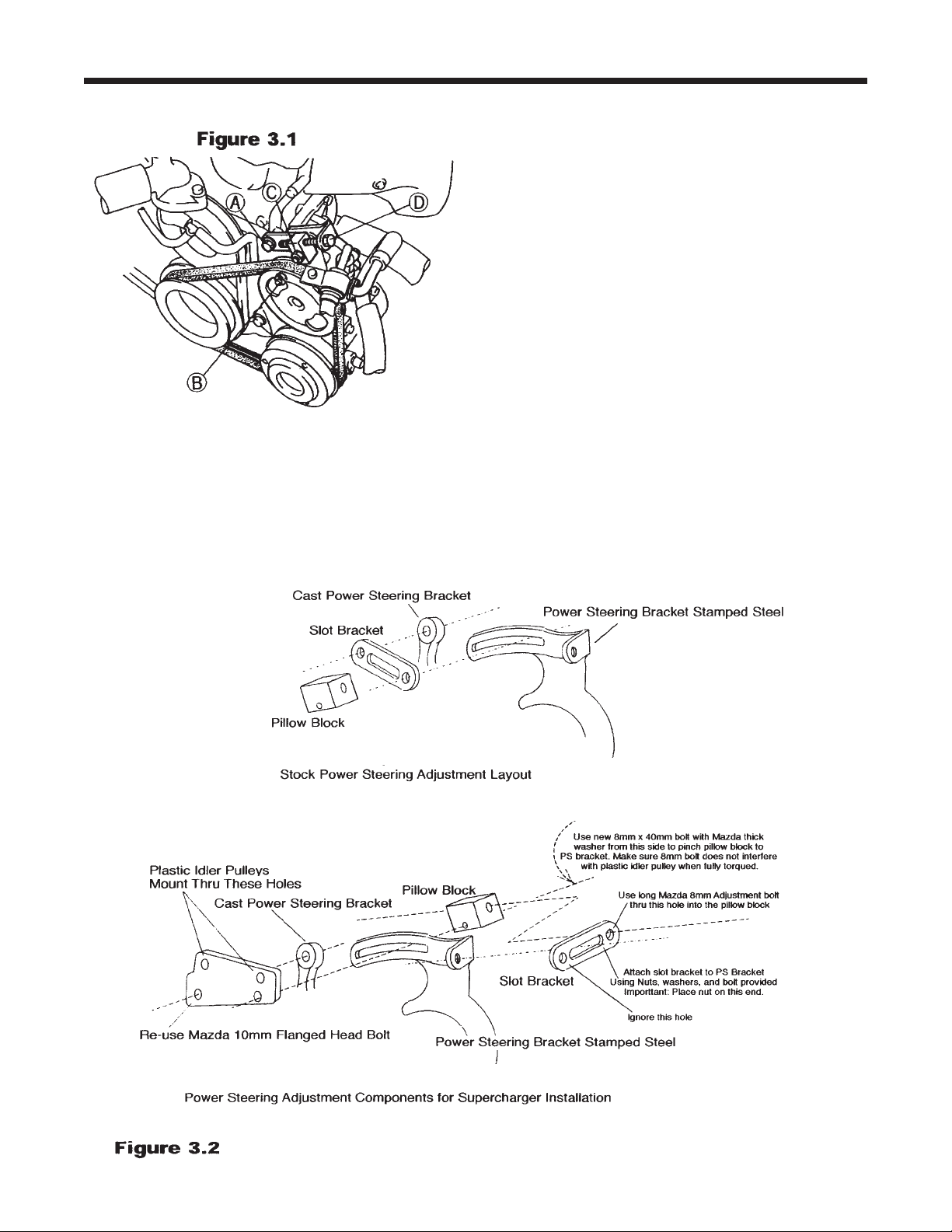
3.0 BELT DRIVES
3.1 NOTE: CARS WITH POWER STEERING:
You will be rearranging your power steering
bracket components per figure 3.2. Referring to
figure 3.1, remove the slot bracket and pillow
block by removing bolts “A”, “C”, and “D”. Take
the flat idler pulley bracket from your kit and trial
fit it to the assembly per figure 3.2. You will be
moving the pillow block and bolt “D” to behind the
power steering stamped steel bracket. This
makes room for the flat idler pulley bracket. The
upper support for the repositioned long bolt “D”
comes from a relocated Mazda slot bracket. It
becomes an extension bracket for bolt “D”. The
slot bracket is attached to the stamped steel
power steering bracket using a new
bolt/washer/nut assembly supplied in your kit.
Make sure to point this bolt with its head nearest
the nylon idler pulley and that this bolt goes
through the slot. The forward hole of the repositioned slot bracket will not be used. The rearward
hole is now used for the relocated “D” bolt, which
will be used to tighten your drive belt. Note: The
power steering pump must be in its lowest position for this procedure.
3.2 When you are done with your trial fitting of
the flat idler pulley bracket, take this flat bracket
to a workbench and install the two nylon idler pulleys using the spacers, bolts and nyloc nuts provided. Make sure that the bolts point toward the
front of the car.
Supercharger Installation Instructions
999-156 -4- Revised 1/07
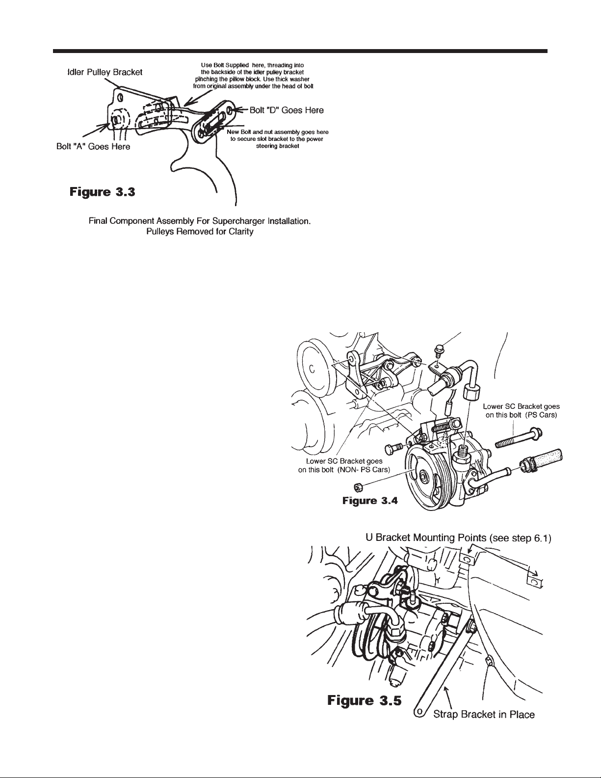
3.3 Secure the idler pulleys firmly to the flat bracket. Proceed to install the idler pulley assembly
onto the car per the procedure practiced during
the trial fitting. The final assembly (minus the pulleys) should look like figure 3.3.
VERY IMPORTANT: MAKE SURE THAT THE
DRIVER’S SIDE IDLER PULLEY IS FREE TO
SPIN. THE PINCH BOLT THAT YOU INSTALL
THROUGH THE PILLOW BLOCK FROM THE
REAR CAN INTERFERE WITH THE BACKSIDE
OF THE IDLER IF INSTALLED INCORRECTLY
(i.e. leaving out the thick washer under the bolt’s
head). TEST THE ASSEMBLY BY TIGHTENING
THE PINCH BOLT FULLY AND SPINNING THE
IDLER PULLEY. USE ADDITIONAL WASHERS
UNDER THE PINCH BOLT’S HEAD IF NECESSARY.
VERY IMPORTANT: Check the clearance
between the small coolant hose that runs from the
base of the thermostat housing and the passenger side plastic idler pulley (see figure 8.1). If the
clearance is less than 1/2 inch between the hose
and the pulley, trim three quarters of an inch of
length off of the thermostat end of the small hose.
Reinstall the hose, reusing the spring clamp. By
removing a small piece of the hose end, the hose
will be pulled away from the idler pulley, avoiding
any damage during operation. This is a critical
area for attention since a hose failure could
cause severe engine damage. Not all cars need
this modification.
3.4 POWER STEERING CARS: Spin the power
steering pump pulley until the nut on the main
pump mounting bolt is visible. Insert a socket
wrench (deep 14mm) here and hold the rear hex
head with a 14mm box wrench. Remove the nut
and the long bolt (item “B” in figure 3.1). The bolt
will retract rearward underneath the exhaust
manifold.
3.5 Pick the flat steel supercharger bracket
from the kit and slip the long power steering
pump mounting bolt through the non-slotted
end. Reinstall the power steering pump bolt
and nut with the flat bracket pinched
between the bolt head and the cast power
steering pump bracket that is on the engine.
When finished, rotate the power steering
pump as far down as possible (the pulley
will touch the AC compressor pulley if so
equipped). This will allow room for the
supercharger to be installed and for the belt
to slip over the pulleys.
Supercharger Installation Instructions
999-156 -5- Revised 1/07
3.6 NON POWER STEERING CARS: Locate
your lower bracket assembly from the kit. The
end with the small 90-degree bracket mounts to
the idler bracket (standard on AC equipped cars)
or to new idler bracket (supplied with kit for nonAC, non-PS cars). Use the new, longer 10mm
bolt provided to attach this bracket to the engine
(Review figure 3.4 for bolt location).
4.0 POWERCARD
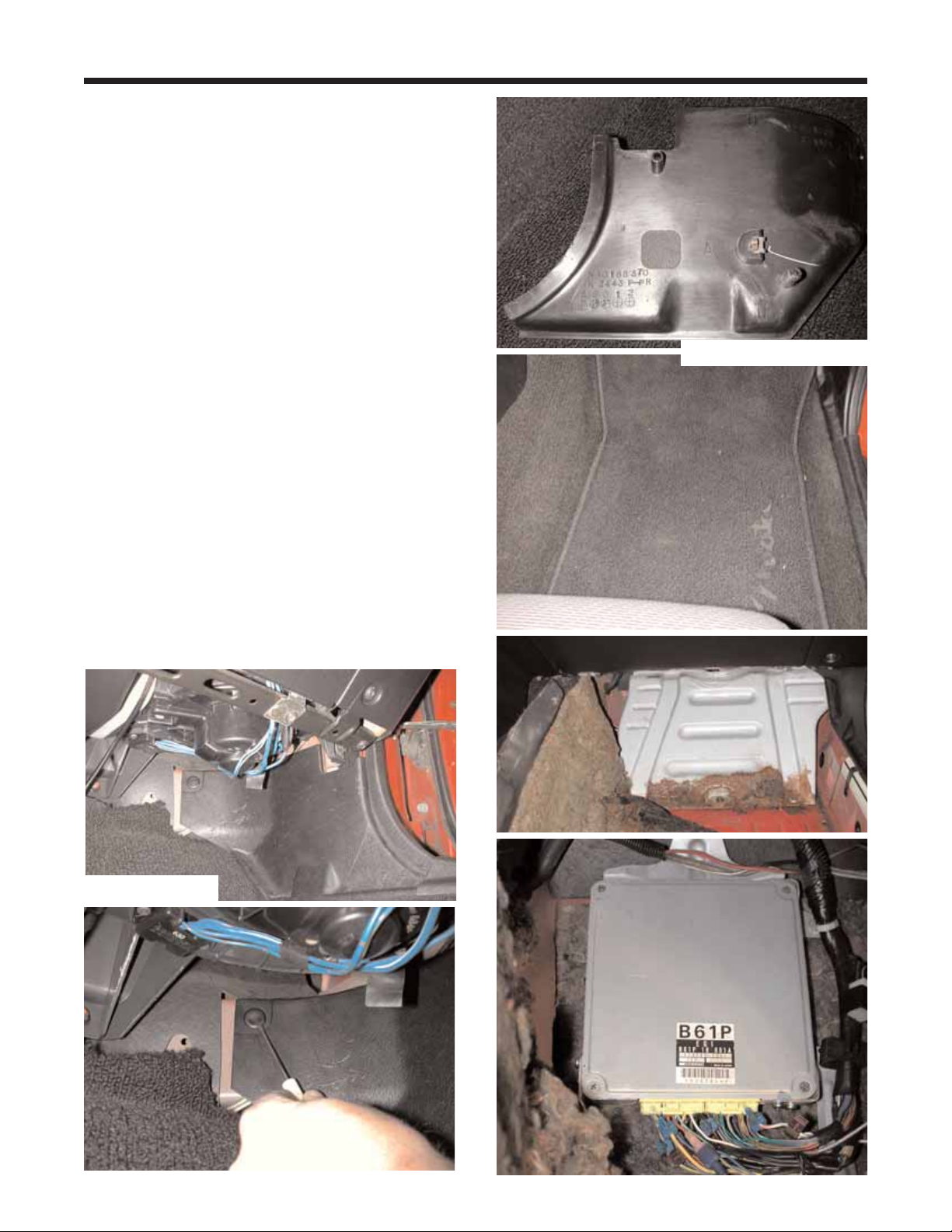
4.1 The Powercard will be installed in the passenger (right hand) foot well. Remove the kick
panel trim by removing the plastic fastener
securing the top, front portion of the panel. Use a
small screwdriver to pull out the center section
and then pull the whole fastener out. There is
also a push in fastener in the center of the panel.
Slip your fingers up behind the panel and gently
pull out on the center until it pops free. Once the
center fastener is free, slide the panel out from
under the door sill trim and set it aside. Remove
the forward two screws from the door sill trim to
allow easy removal and reinstallation of the carpet. Remove the floor mat and pull back the carpet to expose a large metal plate. Using a 10mm
socket, remove the four nuts and one bolt that
secure the plate to the car. Remove the plate to
gain access to the Electronic Control Unit (ECU).
Supercharger Installation Instructions
999-156 -6- Revised 1/07
Illustration 4.1
Illustration 4.1 con’t
 Loading...