

Page 1

1060
40906
MODEL 64/86
C/RPW
TWO TANK RACK CONVEYOR
DISHWASHER
SERVICE MANUAL
INCLUDES:
-Warranty Policy -Basic Functions of Dishwasher
-Installation Requirements -Maintenance and Care
-Operating Instructions -Illustrated Parts List
-Description of Components -Electrical Diagrams
WORLD HEADQUARTERS & MANUFACTURING OPERATIONS
Highway 25E, P.O. Box
Barbourville, KY
888/800-JMSC
Fax: 606/523-9196
April 4, 1997 7610-100-40-00 Rev A
Page 2

INDEX
WARRANTY 2
SPECIFICATIONS 3
GENERAL INSTRUCTIONS (Installation) 8
GENERAL INSTRUCTIONS (Operation) 9
GENERAL INSTRUCTIONS (Preventive Maintenance) 10
REPLACEMENT of SWITCHES in CONTROL PANEL 11
THERMOSTAT 12
WASH TANK and RINSE TANK HEATER SYSTEM 13
WATER LEVEL CONTROL (ELS Heat Circuits) 15
SERVICE INSTRUCTIONS (Incoming Water Solenoid Valve) 17
REPLACING SEAL and CERAMIC on WASH PUMPS 18
CONVEYOR CLUTCH ADJUSTMENT 22
TROUBLE SHOOTING GUIDE 27
ELECTRICAL DRAWINGS 29
PARTS LIST 53
PARTS DISTRIBUTORS 56
Page 3

SPECIFICATIONS
Electric Tank Heat
Steam Tank
Heat
230
Volts
118.1
75-9
18.1 18.1
208
Volts
133.4
86.7 22.8 22.8
380
Volts
N/A 48.3 N/A 13.3
OPERATING CAPACITY (NSF RATED)
Model 64C Model 86CRPW
Racks per hour 239 239
Dishes or glass per hour 5975 5975
REQUIREMENTS
Flow pressure 20 PSI 20 PSI
Pre-wash tank temperature (maximum)
120°F
Wash tank temperature (mini mum) 150°F 150°F
Recirculated rinse tank temperature (minimum) 160°F 160°F
Final fresh water rinse temperature (minimum) 180°F 180°F
Incoming water pipe size — machine 1/2" IPS 1/2" IPS
Incoming water pipe size — pre-wash
1/2" IPS
Drain pipe size 2" IPS 2" IPS
Maximum water usage (final rinse flow rate) 3.8 GPM 3.8 GPM
DIMENSIONS
Length — between dishtables 64" 86"
Width 25" 25"
Height — door closed ± 1/2" 633/4" 633/4"
Height — door open ± 1/2" 70" 70"
Standard table height ± 1/2" 34" 34"
Maximum dish clearance 18" 18"
TANK CAPACITIES
Pre-wash tank
14 Gals.
Wash tank 18 Gals. 18 Gals.
Rinse tank 18 Gals. 18 Gals.
PUMPS AND MOTORS
Pre-wash motor
Pre-wash pump capacity
1/2 HP
80 GPM
Wash motor 1 HP 1 HP
Wash pump capacity 175 GPM 175 GPM
Recirculating rinse motor 1 HP 1 HP
Recirculating rinse pump capacity 175 GPM 175 GPM
Conveyor motor 1/4 HP 1/4 HP
Conveyor speed (feet/minute) 6.56 6.56
ELECTRIC HEAT (WHEN SPECIFIED)
Wash tank 10 KW 10 KW
Rinse tank 13 KW 13 KW
STANDARD RACKS
Dish racks 19 3/4" x 19 3/4" 3 3
Combination racks 19 3/4" x 19 3/4" 1 1
SHIPPING WEIGHT (APPROX.) 750 LBS. 850 LBS.
SHIPPING DIMENSIONS (L x D x H) 120" x 40" x 72" 120" x 40" x 72"
CUBIC FEET 222 ft.3 222 ft.3
ELECTRICAL REQUIREMENTS: 208V/60 HZ/1 or 3
230V/60 HZ/1 or 3 phase
380V/60 HZ/3 phase
460V/60 HZ/3 phase
50 HZ also available in these voltages
Approximate Total Load Amperes
Model 64C
1-Phase 3-Phase 1-Phase 3-Phase
208 Volts 129.1 82.4 18.5 18.5
380 Volts N/A 46.3 N/A 11.3
460 Volts N/A 37.1 N/A 6.9
Model
86CRPW
230 Volts 122.4 80.2 22.4 22.4
460 Volts N/A 39.3 N/A 9.1
All specifications subject to change without notice. 3
Approximate Total Load Amperes
Electric Tank Heat Steam Tank Heat
1-Phase 3-P hase 1-Phase 3-Phase
Page 4
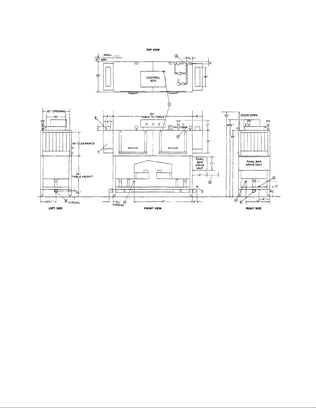
64CE LEFT TO RIGHT
LEGEND
A — MACHINE WATER INLET 1/2" I.P.S. 180°F MIN.
B — DRAIN CONNECTION 2" I.P.S. DRAIN CAN BE CONNECTED TO EITHER END.
C — ELECTRICAL CONNECTION.
D — ALLOW 12" FOR REMOVAL OF PAWL BAR DRIVE UNIT COVER.
E — VENT COLLAR 4" x 16" x 3" TALL, OPTIONAL.
F — VENT COWL, STANDARD.
*G — INCOMING STEAM CONNECTION, OPTIONAL. 3/4" FPT. (GATE VALVE SUPPLIED.)
*H — CONDENSATE RETURN CONNECTION 3/4" FPT. (RETURN TO BOILER OR OPEN DRAIN.)
*STEAM TANK HEAT ONLY
4
Page 5
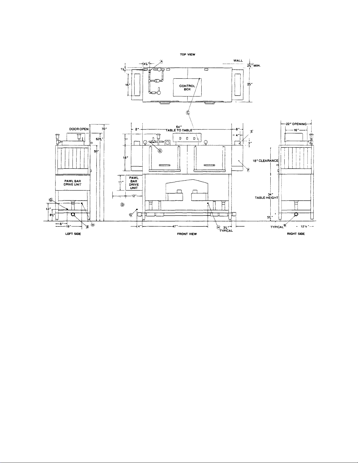
64CE RIGHT TO LEFT
LEGEND
A —MACHINE WATER INLET 1/2" I.P.S. 180°F MIN.
B — DRAIN CONNECTION 2" I.RS. DRAIN CAN BE CONNECTED TO EITHER END.
C — ELECTRICAL CONNECTION.
D — ALLOW 12" FOR REMOVAL OF PAWL BAR DRIVE UNIT COVER.
E — VENT COLLAR 4" x 16" x 3" TALL, OPTIONAL.
F — VENT COWL, STANDARD.
*G — INCOMING STEAM CONNECTION, OPTIONAL. 3/4" FPT. (GATE VALVE SUPPLIED.)
*H —CONDENSATE RETURN CONNECTION 3/4" FPT. (RETURN TO BOILER OR OPEN DRAIN.)
*STEAM TANK HEAT ONLY
5
Page 6
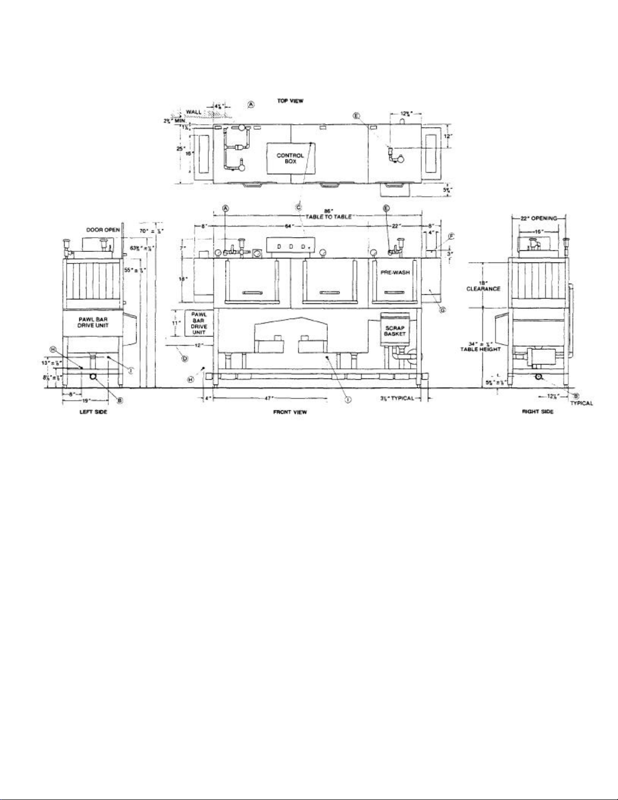
86CERPW RIGHT TO LEFT
LEGEND
A — MACHINE WATER INLET 1/2" I.P.S. 180°F MIN.
B — DRAIN CONNECTION 2" I.RS. DRAIN CAN BE CONNECTED TO EITHER END.
C — ELECTRICAL CONNECTION.
D — ALLOW 12" FOR REMOVAL OF PAWL BAR DRIVE UNIT COVER.
E — PRE-WASH WATER INLET 1/2" I.P.S. 140°F.
F — VENT COLLAR 4" x 16" x 3" TALL, OPTIONAL.
G — VENT COWL, STANDARD.
*H — INCOMING STEAM CONNECTION, OPTIONAL. 3/4" FPT (GATE VALVE SUPPLIED.)
*l — CONDENSATE RETURN CONNECTION 3/4" FPT. (RETURN TO BOILER OR OPEN DRAIN.)
*STEAM TANK HEAT ONLY
6
Page 7
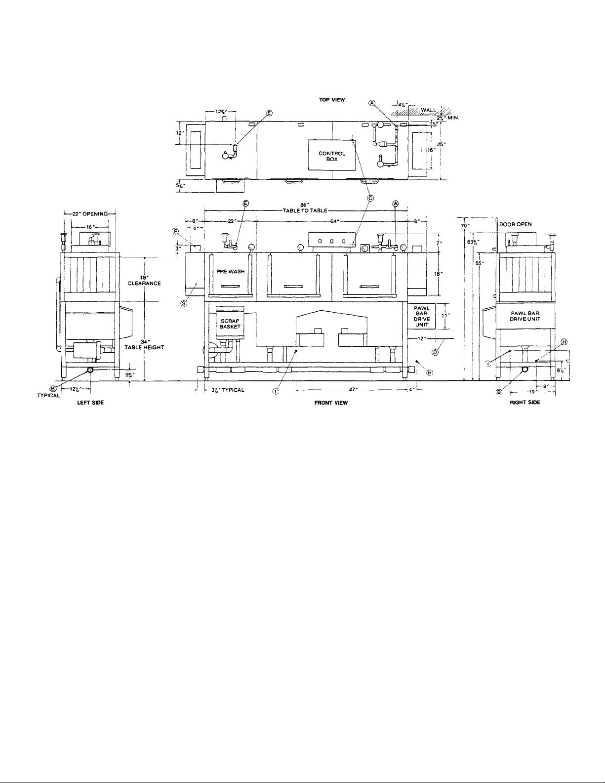
86CERPW LEFT TO RIGHT
LEGEND
A — MACHINE WATER INLET 1/2" I.RS. 180°F MIN.
B — DRAIN CONNECTION 2" I.P.S. DRAIN CAN BE CONNECTED TO EITHER END.
C — ELECTRICAL CONNECTION.
D — ALLOW 12" FOR REMOVAL OF PAWL BAR DRIVE UNIT COVER.
E — PRE-WASH WATER INLET 1/2" I.P.S. 140°F.
F — VENT COLLAR 4" x 16" x 3" TALL, OPTIONAL.
G — VENT COWL, STANDARD.
*H — INCOMING STEAM CONNECTION, OPTIONAL. 3/4" FPT. (GATE VALVE SUPPLIED.)
*l — CONDENSATE RETURN CONNECTION 3/4" FPT. (RETURN TO BOILER OR OPEN DRAIN.
*STEAM TANK HEAT ONLY
7
Page 8

GENERAL INSTRUCTIONS
(INSTALLATION for 64C/86CRPW)
Note: Read the following instructions carefully. Proper installation of your Jackson
Dishwasher will assure proper machine operation.
1. Open the front doors and hook open. Remove dish, cup, and glass racks and set aside for later
use. Remove the tape holding the overflow tubes, the pump intake strainers, and the wash and
recirculating rinse tubes that are in the machine.
2. Cut the straps holding the machine to the base of the crate. Ease the machine on to the floor and
slide into place of installation.
3. Remove the plug provided on either end of the drain plumbing (whichever side is convenient), and
connect the drain (2" female IPS) with the proper slope to conform with local and/or national
codes. Drain is a gravity feed system from the machine.
4. Connect incoming 1/2" water line with capacity to supply 3.8 gallons per minute at 20 PSI flow
pressure and at a temperature of 180°F minimum. For the 86CRPW, another 1/2" water line must
be connected to the pre-wash section to supply 140°F. These connections are just before the Ystrainer on top of the machine. Make connections to conform to local and/or national codes.
5. Electrical connections should be made through the hole in the back of the control box to the
terminal board on the back right -hand side. This terminal board is accessible by removing the
control box cover. The terminals are marked L1, L2 (single-phase), or L1, L2, L3 (three phase).
Be sure all connections conform to local and/or national codes . Refer to data plate for voltage and
amperage totals.
6. DO NOT APPLY POWER UNTIL STEP 9!!!!
7. Make sure drains are closed and the curtains are in place. The long curtains go on the outside of
the vent cowls. The short curtains go on the inside of the ve nt cowls. A medium curtain goes
between the pre-wash and wash tanks. A long curtain goes between the wash and recirculating
rinse tanks. A short curtain goes between the recirculating rinse and final rinse.
8. Turn lever operated drains (if so equipped) to the closed position. Turn on hand valves controlling
water supply to machine. Check for any leaks in the plumbing.
9. To energize electrically, proceed as follows:
a. Turn on customer's circuit breaker controlling the machine.
b. Check voltage at the incoming terminals L1, L2, and L3 (if applicable). It should match the
data plate voltage. Voltage at L1 and L2 should be checked to ground individually to ensure
that a high (or wild) leg is not connected to L1 or L2.
c. If voltages are in the required range, turn on the 20-amp circuit breaker. The 20-amp circuit
breaker protects the control circuits only; it is not meant to protect the wash and recirculating
rinse heaters or motors.
10. a. Turn fill handle(s) on the top of the machine to supply the unit with water. When the required
level is reached, turn the fill handle(s) back to the original position. Open the doors and check
the water level. It should be within 1/4" below the overflow level.
b. If unit is equipped with the Auto-Fill option, fill by turning on the power switch and pushing and
releasing the Auto-Fill Switch. (Warning: If unit does not continue to fill when switch is
released, immediately turn power switch off. Clean probes located in wash tank [and pre-
wash, if 86CRPW] and try again. If problem persists, call service agency.) Fill will shut off
automatically when proper level is reached.
11. When the water has reached the proper level, close the doors and turn on the power switch. The
heaters are in the wash and recirculating rinse tanks. They are utilized to maintain the wash water
temperature at 150°F, and the recirculating rinse water temperature at 160°F.
12. Turn the manual switch on by pushing and releasing the momentary side of the switch. This will
activate a hold circ uit and the pumps, conveyor, and final rinse will come on and run continuously.
Turn manual switch off.
13. Turn the auto switch on by pushing and releasing the momentary side of the switch. This will
activate a hold circuit, but nothing will come on until a rack is inserted into the machine. Insert rack
into the soiled side of the machine. The pumps, conveyor, and final rinse will come on. Allow the
rack to travel all the way through the unit. The pumps, conveyor, and final rinse will shut off
automatically when the rack leaves the unit.
8
Page 9

14. The unit is now ready to proceed with the washing of dishes in accordance with the operating
instructions.
Note: As the racks leave the unit, do not allow them to accumulate more than three in a row.
GENERAL INSTRUCTIONS
(OPERATION of 64C/86CRPW)
Note: Read instructions carefully. Proper operation of your Jackson Dishwasher will asssure
clean and sanitized glasses and dishes at optimum efficiency.
Dish Preparation:
1. Scrape the dishes thoroughly.
2. Pre-rinse the dishes by soaking or by spraying off with a pre-rinse hose.
3. Place the dishes and cups in the dish rack with the cups upside down.
4. Place the glasses and silverware in the combination glass-silverware rack with the glasses upside
down. Scatter the silverware loosely on the bottom of the rac k. DO NOT put glasses on top of the
silverware.
Note: When the silverware is in any upright position, it washes and rinses better than
lying flat. These compartment silverware racks are available through your dealer or
service agency.
Machine Operation:
1. Open the doors and insert pump intake strainers, overflow tubes, pan strainers, and the upper and
lower wash and rinse tubes.
2. Make sure drains are closed and the curtains are in place. The long curtains go on the outside of
the vent cowls. The short curtains go on the inside of the vent cowls. A medium curtain goes
between the pre-wash and wash tanks. A long curtain goes between the wash and recirculating
rinse tanks. A short curtain goes between the recirculating rinse and final rinse.
3. Close the doors.
4. a. Turn on the fill valve handle(s) on top of the unit. When the proper level is reached, turn off
the fill valve(s).
b. If the unit is equipped with the Auto-Fill option, fill by turning on the power switch and pushing
and releasing the auto fill switch. (Warning: If unit does not continue to fill when switch is
released, immediately turn power switch off. Clean probes located in wash tank [and pre-
wash, if 86CRPW] and try again. If problem persists, call an authorized service agency.) Fill will
shut off automatically when proper level is reached.
5. Turn on the power switch and allow the wash and rinse water to reach proper temperature (wash
150°F, recirculating rinse 160°F).
6. Select either automatic mode or manual mode. In the manual mode, the dishwasher will run
continuously. In the automatic mode, the dishwasher will run only when a rack of dishes is in the
machine. Activate desired mode by pushing the proper mode switch to the momentary position
and releasing. Make sure the opposite mode switch is in the 'off' position.
7. Slide in a rack of dirty dishes. If machine is in the automatic mode, the rack will activate the paddle
switch, and the machine will remain on long enough for the rack to pass through. Then, the unit
will shut off. Each successive rack will reset the cycle. This is an energy -saving feature when
intermittent use is required rather than continuous use.
8. When the rack leaves the other end of the machine, it should be removed and not allowed to
accumulate more than three rac ks on the table. Failure to remove the racks could result in
damage to the conveyor system. (If so equipped, accumulated racks will open the table limit
switch which will shut down the machine until the racks are removed.)
9. At the end of a meal period, shut off the power switch. Drain the unit by operating the drain valves
(if so equipped) or by removing the overflow tubes. Clean all the strainers and flush out the unit.
9
Page 10

GENERAL INSTRUCTIONS
(PREVENTIVE MAINTENANCE for 64C/86CRPW)
(To be performed as needed*)
Note: Read carefully. Proper maintenance of your Jackson Dishwasher will ensure optimum
service with a minimum of down time.
1. Remove all lime and corrosion deposits.
a. Fill the machine with water as normal.
b. Open doors and place de-liming compound into the wash and rinse water in accordance with
the directions on the label. (Both tanks hold 18 gallons.) Close doors.
c. Turn on the machine in the manual mode and allow to run for 5 minutes.
d. Turn off the machine, open doors and inspect the interior. All lime should be removed and
parts should appear shiny. If not, allow to run for a longer period.
e. When the interior of the machine is clean, drain the water and refill.
f. After refilling, allow machine to run for 2 minutes and drain again.
g. Refill machine and resume normal operation.
2. Clean strainers (every meal period or more).
a. Turn off unit and drain water.
b. Remove and clean all strainers thoroughly.
c. Replace strainers and refill machine. Resume normal operation.
3. Clean wash and rinse tubes.
a. Remove wash and rinse heads by lifting the holding clip and sliding out.
b. Remove end plugs by unscrewing.
c. Flush tubes with water until clean.
d. Reassemble and replace.
4. Clean final rinse heads.
a. Remove end plugs.
b. Clear spray nozzles using a pointed tool.
c. Close doors and activate cycle momentarily.
d. Replace end plugs.
5. Clean Y-strainer on incoming water line.
a. Turn off water to the machine.
b. Relieve line pressure by opening fill valve.
c. Remove plug and strainer. Clean using a brush and de-limer.
d. Replace strainer and plug.
6. Clean exterior of the machine using a stainless steel polish.
10
Page 11
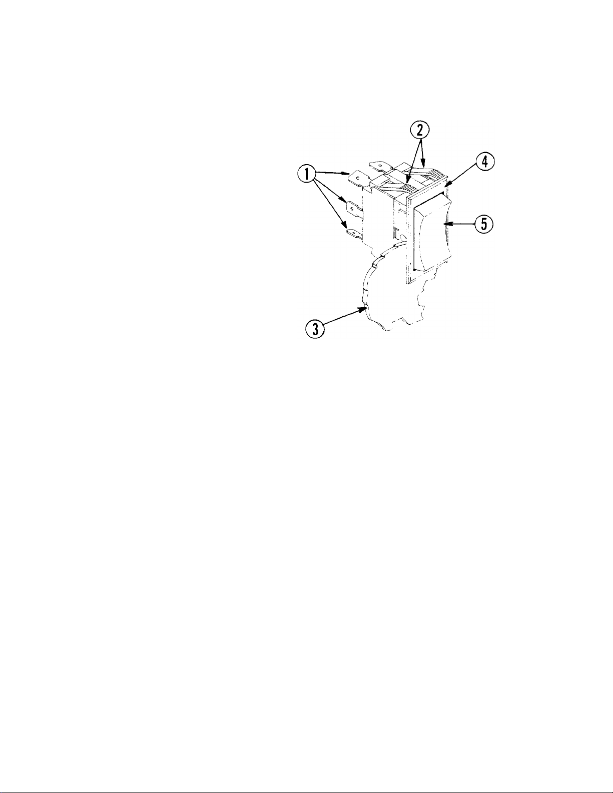
REPLACEMENT of SWITCHES
1.
CONNECTION TERMINALS
2. RETAINING CUPS
3. FRONT PANEL
4. SWITCH BEZEL
5. ROCKER BUTTON
in CONTROL PANEL
There are three switches installed in the control box front panel. These are the power, automatic
wash and manual wash switches.
Before working on the machine, it is important that power be turned off at customer's circuit breaker.
To prevent the possibility of electrical shock, trip breaker to "off" position. Then turn the machine
breaker located on the right side of the power box to "off".
Remove the cover from the control box by unlocking latch and lifting off cover.
If a switch is found to be defective, insert a new one into the cutout in the control box. Replace the
wires from the used switch, terminal by terminal, ont o the new switch.
Power can now be applied to the dishwasher and run through cycles checking all operations.
11
Page 12
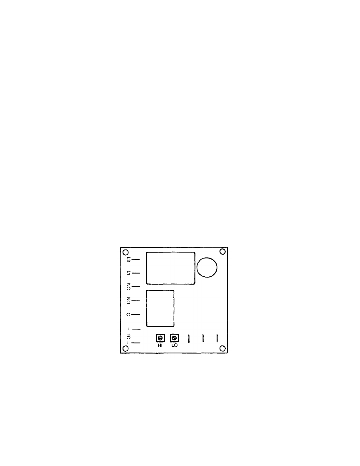
THERMOSTAT
The electronic thermostat can be adjusted on both the 'HI' (off) setting, and the 'LO' (on) setting by
use of the corresponding control pot. Turning the control pot counterclockwise (CCW) will lower the
setting. Clockwise (CW) will raise the set ting. When adjusting the thermostat, adjust the 'HI' setting
first.
To Adjust the Thermostat:
1. Fill unit with water, then turn the power switch "on".
2. Allow the water to reach the desired 'HI' (or turn off) temperature. This temperature should be
approximately 160°F for the wash, or 170°F for the power rinse. (It may be necessary to turn 'HI'
control pot CW all the way to stop in order to prevent heaters from shutting off before temperature
is reached.)
3. When desired temperature is reached, slowly turn 'HI' control pot CCW until relay cube clicks "off"
(N.C.).
4. Turn the 'LO' control pot CCW all the way to stop.
5. Turn on the manual wash and allow the unit to run until water temperature reaches the desired
'LO' (or turn on) temperature. This temperat ure should be approximately 153°F for wash, and
163°F for power rinse.
6. Turn the 'LO' control pot CW until relay cube clicks "on" (N.O.).
Note: If relay will not operate, check power to thermostat. Thermostat can be tested by
placing jumper wire across T.C. terminals, bypassing thermocouple.
12
Page 13

WASH TANK and RINSE TANK
HEATER SYSTEM
Function:
The wash and rinse tank heater system are electrically connected in the circuit so that they are
dependent upon the dishwasher being property filled with and maintaining a safe water level.
The circuits are controlled by a power switch (mounted on the front control panel), two thermostats
(mounted in the junction box behind the lower front panel), two water level controls (mounted in the
control box), and two heater relays (mounted in the control box), with the coils being activated by the
thermostats.
indicators of Possible Malfunction:
Once the machine has been properly filled, the heat circuit should operate by merely turning on the
power switch. Should the tank heat, be it either too high, too low, or no indication of temperature at all,
the following checkouts should be made.
Checkout the Heater System for Tank (Refer to drawing, figure 1):
Note: The following checkouts should be done by a qualified service person or electrician.
1. If temperature is too high, adjust thermostat, using thermostat instructions in this manual.
2. If temperature is too low, adjust thermostat as above, then:
a. Turn off power to machine by tripping customer's circuit breaker to "off" position. Turn off
machine circuit breaker located on right side of power box.
b. Remove cover from control box on top of machine.
c. Make sure water temperature is below 140°F (preferably about 130°F).
d. Turn on both circuit breakers. Observe heat relay (3 or 4 pole, mounted lower left inside
power box) while power switch is turned "on" and "off". If relay contacts move in and out,
heat relay is ok; if not, proceed to "A".
If Heat Relay Closes:
1. Check power supply at incoming terminal board L1, L2, L3. It should be data plate voltage across
each leg.
2. Check power at positions 4, 5, and 6, figure 1. It should be data plate voltage. If not, check wires
for breaks or bad connections.
3. Check power at positions 7, 8, and 9. It should be data plate voltage. If not, check wires for breaks
or bad connections.
4. Temperature should rise as explained in "A-1", and amperages may be checked according to
those instructions. Replace any defective elements.
13
Page 14
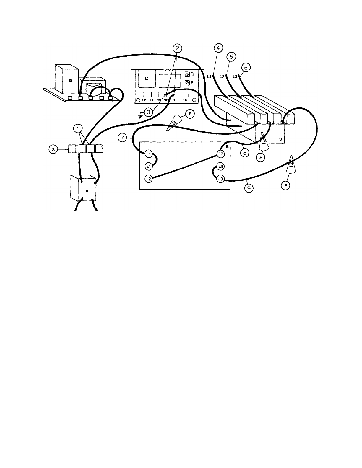
FIGURE NO. 1 HEATER SYSTEM 3-PHASE
A. POWER SWITCH
B. WATER LEVEL CONTROL
C. THERMOSTAT
D. HEATER RELAY
E. TANK HEATERS
F. AMPROBE TEST POSITION
X. TERMINAL BOARD (TERMINALS)
A. If Heat Relay Does Not Close:
1. There is an insulated movable bar on the relay across the top of the contacts. With
insulated probe, depress this bar and observe the thermometer; the temperature should rise noticeably in a
minute or two. If it moves slowly, it would indicate that the element is faulty. If it moves constantly higher at
a good rate, elements should be ok.
2. With power switch on:
a. Check position 1, figure 1. Voltage should be 220V; if not, checkout power switch and
replace if necessary.
b. Check position 2; there should be no voltage. If there is, readjust thermostat per
thermostat adjustment instructions.
c. Check position 3; voltage should be approximately 120V to ground.
d. If voltage being applied on positions 1, 2, and 3 checks out okay, then the relay should be
replaced. Coil is probably defective.
Note: A check with an amp probe at positions shown in figure 1 can be made. The amp
draw on each leg should be appropriate for the voltage and phase as indicated by the
data plate.
14
Page 15

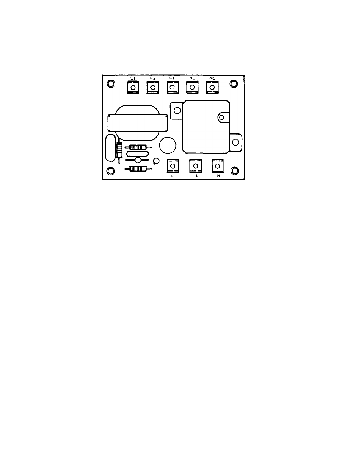
WATER LEVEL CONTROL
(ELS HEAT CIRCUITS)
This control is activated when the power switch is turned on. The primary function is to automatically
activate the wash and rinse tank heat circuit. It will also provide cutoff of the wash and rinse heat
circuit, should the water be accidentally drained from the machine (with the power switch still on). The
power switch should always be turned off before draining.
This water level control is used in conjunction with two probes (sensors), power switch, thermostats,
and heat relays.
When the power switch is turned on, the normally closed circuit in the plug-in relay is energized.
As the water rises in the wash and rinse tubs it will cover the probe (directly above wash element). At
this time, the plug-in relay coil will be activated and open the normally closed contacts.
Simultaneously, the contacts will close on the normally open circuit, energizing the wash and rinse
heat circuits. (Checkout and information concerning that part of the circuit are in the wash heater
system or rinse heater system instruction page of this manual.)
If the water should be drained from the machine while the power switch is still on, the probe will
sense the lack of water and de-energize the plug-in relay, which will de-energize the wash and rinse
heat circuit. DO NOT DEPEND ON THIS — always turn power switch off before draining.
Symptoms of Level Control Failure:
1. Wash or rinse heat circuit does not activate.
2. Wash heater remains on (if wash water emptied with power switch on).
3. Rinse heater remains on (if rinse water emptied with power switch on).
Proceed with Checkout:
1. Remove power to machine by turning customer's circuit breaker to its "off" position. Turn machine
circuit breaker, located on right side on power unit box, to "off."
2. Remove cover to control box.
3. Locate malfunctioning water level control board and disconnect wires going to terminals marked
C, H, and L. Mark and insulate wires for replacement.
4. Be sure affected tank is empty and power switch is off. Carefully reapply power to machine. Begin
by turning power switch on. With an insulated jumper wire, touch jumper between terminals C &
H; relay in clear plastic cube should activate as wire is touched to terminals. Observe relay
contacts — they should pull in. If they do, remove wire and they should return to original position.
Repeat several times to verify action. Reconnect wires removed.
5. If relay operates, the control can be deemed operational and other causes should be explored.
EXAMPLES: 1. Loose or broken wire to probe or ground (green wire).
2. Dirty probe(s).
3. Thermostat faulty or needs adjustment. (See instruction page concerning
thermostat.)
4. Wash element faulty. (See instruction page concerning wash-heat checkout.)
5. Rinse element faculty.
6. If relay does not operate, check voltage being applied to L1 - L2 marked on control. It should be
208-230V. Replace control, if necessary.
15
Page 16
7. In any case, always locate sensor (probes) inside wash tub and clean off all deposits. (Instruct customer;
this should be at least a weekly project.)
8. Remove power to machine and replace panel and any wires that were not replaced previously.
16
Page 17
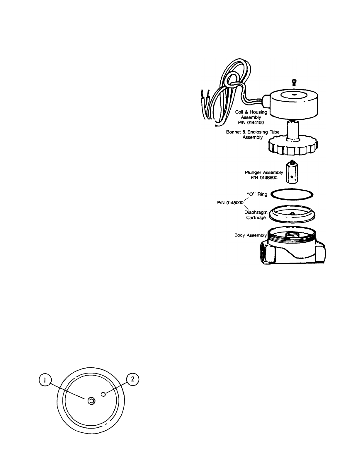
SERVICE INSTRUCTIONS
#2
(INCOMING WATER SOLENOID VALVE)
To Take the Valve Apart:
Disassembly — These valves may be taken apart by
unscrewing the bonnet and enclosing tube assembly from the
valve body assembly. See figure 2. After unscrewing, carefully
lift off the bonnet and enclosing tube assembly Don't drop the
plunger. The "0" ring seal and diaphragm cartridge can now be
lifted out.
Be careful not to damage the machined faces while the valve is
apart.
To Reassemble — Place the diaphragm cartridge in the body
with the pilot port extension UP. Hold the plunger with synthetic
seat against the pilot port. Make sure the "0" ring is in place,
then lower the bonnet and enclosing tube assembly over the
plunger. Screw bonnet assembly snugly down on body
assembly.
DIAPHRAGM CARTRIDGE
P/N 0145000
Pilot port extension #1 clogged.
Hole #2 clogged.
F
FIGURE NO. 2
Possible Problems:
Remedy:
Pass heated straight pin through hole
17
or clean hole #1.
Page 18

REPLACING SEAL and CERAMIC
on WASH PUMPS
Function:
The pump is part of the total motor-pump system and utilizes one shaft seal and ceramic to prevent
the pump from leaking around the impeller and shaft. One gasket is used to prevent leakage between
the pump mounting plate and the machine pump plate.
Replacement of Seal and/or Ceramic:
1. Remove the power source to the machine by turning the circuit breaker to its "off" position on the
side of the control box.
2. Drain the machine by removing the overflow strainer in the wash tank.
3. Support the motor — remove the four nuts holding the pump/motor to the machine's pump plate.
4. Carefully pull motor outward, move from side to side as required to remove from machine.
5. Set motor and pump on a sturdy stand close to machine or remove wires and conduit to allow
motor/pump to be moved to a better work station.
6. Insert a firm object into the blades of the fan and use 15/16" ratchet to remove bolt holding
impeller. After the bolt is removed, pull the impeller up and off of the shaft.
7. The ceramic is imbedded in the pump mounting plate and usually does not need replacement, but
the seal normally would when water leaks around the motor shaft area. If replacement of either is
required, proceed as follows:
a. Remove the four bolts holding the pump mounting plate to the motor.
b. Slide the mounting plate up and off the shaft and motor. The imbedded ceramic and shaft
seal will be removed with the mounting plate.
c. Turn over the plate and push the seal and/or ceramic out of the housing carefully. It may be
necessary to break the ceramic to remove it.
d. Clean the hole where the ceramic was installed.
e. Lightly coat with a lubricant around the new ceramic's edges and "0" ring. Gently press the
ceramic into place against the snap ring in the housing. Make sure that the grooved side of
the ceramic faces the motor and housing snap ring, leaving the smooth side toward the
impeller.
f. Make sure that the woodruff key is in place in the shaft and then set the plate bac k on the
motor over the shaft.
Note: A field tool can be made (to ease installation of seal) from a pipe or tube (3/4"
CPVC typical example) that has proper outside and inside dimensions. It must fit
over step down in shaft, but be close to larger shaft size on outside. To
acommodate woodruff, cut long slot in tube. Lubricate tube. Slip seal over tube
onto shaft.
g. Lightly coat with a lubricant the new seal face and gently press it into place over the shaft
with seal face against the ceramic. SEE NOTE ABOVE.
h. Place the spring over the shaft with the metal cap up. Press the impeller down onto the shaft,
aligning the keyway of the impeller with the woodruff key.
i. Tigthten the impeller washer, lockwasher, and bolt into place. Replace the four bolts that hold
the mounting plate to the motor.
8. Reinstall the pump and motor in the unit by reversing steps one through eight. (It is suggested that
a new pump gasket be installed.)
Impeller Rotation:
When facing the impeller after mounting it on the motor shaft, the impeller should turn in a
CCW direction.
18
Next Page
Page 19

ITEM P/N DESCRIPTION
1.
2. 0106500 WOODRUFF KEY
3.
4. 0108000 SNAP RING
5. 0105000 CERAMIC FACE W/"0" RING
6. 0104500 PUMP MOUNTING PLATE
7. 0105000 SEAL FACE
8.
9. 0105000 SEAL ASSEMBLY (SEAL SPRING
10. 0105500 PUMP IMPELLER
11. 0107500 IMPELLER WASHER
12. 0107000 IMPELLER BOLT & LOCKWASHER
13. 0106000 PUMP MOUNTING GASKET
PUMP MOTOR
WASHER, RUBBER
PLATE TO MOTOR MOUNTING
BOLTS & LOCKWASHERS
& CUP WASHER)
19
Page 20

CAM AND CLUTCH ASSEMBLY
ITEM P/N DESCRIPTION
1.-8. 0038501 CLUTCH, TORQUE LIMITER
9. 0039001 CLUTCH ADAPTER PLATE
10. 0038100 FOLLOWER BEARING LOCKNUT
11.
12. 0037501 DRIVE BOLTS 10-32
13. 0038001 FOLLOWER BEARING
14. 0035001 SHAFT ADAPTER
15. 0039501 CAM WHEEL BUSHING
16. 0037501 DRIVE BOLT
CAM WHEEL
20
Page 21

CONVEYOR DRIVE ASSEMBLY AND MOTOR
ITEM P/N DESCRIPTION
1. 0039001 CLUTCH ADAPTER PLATE
2. 0036100 DRIVE ROD BEARING BRACKET
3. CAM WHEEL
4. 0038001 CAM FOLLOWER BEARING
5. 0035300 DRIVE ARM
6. 0041000 SHOULDER SCREW 1/4"
7. 0035500 ARM LINKAGE
8. 0040500 ROD WIPER
9. 0040000 DRIVE ROD BEARING
10. 0036000 DRIVE ROD ARM
11. DRIVE MOTOR & GEAR HEAD
21
Page 22

CONVEYOR CLUTCH ADJUSTMENT
This procedure is to be used should it be necessary to adjust the conveyor drive clutch.
1. Remove the cover from the conveyor drive assembly.
2. Loosen the (2) setscrews in the clutch adjustment nut at least 8 full turns.
3. Using a torque wrench and a crowfoot adapter, carefully adjust nut to a torque reading of
30 in-lbs.
4. Retighten setscrews.
FIGURE NO. 3:
22
Page 23

ITE
P/N DESCRIPTION
3. 0044700
PAWL BAR NUT
1/4"
x
20"
S/S
5. 0043500
PAWL BAR SPACER PIN
7. 0044500
PAWL BAR CONNECTOR PIN
8. 0044600
S/S
PAWL BAR ASSEMBLY
23
1. 0045000 PAWL BAR DOG STOP
2. 0043001 PAWL BAR PAWL (DOG)
4. 0011200 LOCK WASHER
6. 0044000 PAWL BAR SPACER BUSHING
PAWL BAR BOLT 1/4" x 20" x 3/4"
Page 24

WATER LEVEL
PROBE ASSEMBLY
1.
PROBE BODY
25
P/N 0084500
2. NUTS
3. LOCKWASHER
BREAKER VACUUM ASSEMBLY
P/N 0184101
ITEM P/N DESCRIPTION
1. BONNET
2. 0184200 DISK
3. 0184200 GASKET
4. 0184200 POPPET
5. BODY
Page 25

HEATER ELEMENT
13
KW HEATER
SHORT HANDLE
LEVER OPERATED
DRAIN ASSEMBLY
P/N
0054003
2. DRAIN VALVE
4. STRAINER
7.
STOPPER
1. VALVE BODY
3. FLANGE
5. "0" RING
6. RETAINING NUT
8. "0" RINGS, STOPPER
9. HANDLE, SHORT
WASH 10 KW
POWER RINSE
ELEMENT
ELECTRIC TANK HEAT ELEMENT
26
Page 26

TROUBLE SHOOTING GUIDE
power into the switch and out of
the switch,
check back to circuit
but not out of the switch, replace
Motor to see that there are no
T.O.L. heater. If open, replace
Terminals and connections, and
Them, then with a short link of
and "H". These terminals are on
PROBLEM CAUSE SOLUTION
Water level to low in wash tank.
Water level to low in rinse tank. damaged.
Water level to low in pre-wash
tank. 2. Water trough not adjusted 2. Adjust trough.
Pawl bar moves with no load but 1. Clutch slipping. 1. Adjust clutch. (See page insert
does not move when loaded.
Wash and rinse pumps don't run. 1. Auto or manual switch is 1. With auto or manual switch on,
Conveyor motor doesn't operate. 1. Conveyor motor thermal 1. Push reset bar on component. If
1. "0" ring not in drain fitting or
properly.
defective.
2. Loose wires or connections. 2. Check all wiring to and from
3. Pump jammed. 3. Clean pump housing.
overload relay has opened.
1. Check to see that there is an "0"
ring in the drain fitting and it is
necessary.
for instructions of Torque Tamer.)
check to see that you're getting
breaker on dishwasher. If you are,
switch.
Loose connections or broken or
Frayed wires. Repair or replace
as necessary.
Motor is still inoperable, check
Heater.
2. Clutch is slipping but conveyor 2. Adjust clutch.
motor is operating.
3. Loose wires or connections. 3. Check all wiring for breaks, loose
Repair accordingly.
4. Motor is defective. 4. Motor hums or doesn't operate at
All. Defective, replace motor.
Heat circuit does not operate 1. Water level in rinse or wash 1. Fill rinse or wash tank to
(rinse or wash tank not at required
temperature). probe.
tank below low water cutoff
2. Thermostat is out of adjustment 2. Refer to section regarding
or defective. thermostat adjustment.
3. Water level control is defective. 3. Check to see that the terminals
4. Water-level control checked out 4. Make sure that the probe wire
okay but heat circuit still does has been replaced.
not operate.
5. Rinse element is defective. 5. Replace element.
Overflow level.
L1 and L2 on the water-level
Control have power coming to
insulated wire, jump terminals "C"
the low voltage (24V) system.
If low water control is operating,
The contacts in the little plastic Coated relay will work or move.
(Before attempting above, remove
Wire to water-level probe.)
27
Page 27

TROUBLE SHOOTING GUIDE
PROBLEM
CAUSE
SOLUTION
Vacuum breaker is allowing water
to escape and spray on top of
1. Vacuum breaker is defective.
2. Gasket on poppet split or worn.
1. Remove top of vacuum breaker
by unscrewing. Lift poppet out and
2. Replace rubber gasket and
washer on poppet completely.
Page 28

Page 29

Page 30

Page 31

Page 32

Page 33

Page 34

Page 35

Page 36

Page 37

Page 38

Page 39

Page 40

Page 41

Page 42

Page 43

Page 44

Page 45

Page 46

Page 47

Page 48

Page 49

Page 50

Page 51

Page 52

COMPLETE PARTS LIST for 64C/86CRPW
0029800
Control Box, Lock
0034800
Conveyor Drive Motor,
1/4
HP, 220V,
60
CY,
1
PH,
45
RPM (For
50
Cycle Units)
0035001
Conveyor Drive Shaft Adapter, For Motor
0035500
Conveyor Drive Arm Linkage
0036000
Conveyor Drive Rod Arm
0036100
Conveyor Drive Rod, Bearing Bracket Assembly
0036600
Conveyor Drive Cam and Clutch Assembly
0037501
Conveyor Drive, Socket Head Bolt
0038001
C
onveyor Drive Cam Follower Bearing
0038100
Conveyor Drive Cam, Follower Bearing Locknut
0038501
Conveyor Drive Clutch, Torque Limiter
0039001
Conveyor Drive Clutch, Adapter Plate
0039501
Conveyor Drive Bushing, for Cam Wheel
0040000
Conv
eyor Drive Rod Bearing
0040500
Conveyor Drive Rod Wiper
0041000
Conveyor Drive Shoulder Screw, 1/4"
0041500
Conveyor Drive Shoulder Screw,
3/8"
0042400
Conveyor Pawl Bar Idler Roller Bushing
004270
0
Conveyor Pawl Bar Assembly
(64")
0042800
Conveyor Pawl Bar Side
(64")
0042900
Conveyor Pawl Bar, Drive Connector Pin
0043001
Conveyor Pawl Bar Pawl (Dog)
0043100
Conveyor Pawl Bar Assembly
(86")
0043200
Conveyor Pawl Bar Side
(86")
0043500
Conveyor Pawl Bar Spacer Pin
0044000
Conveyor Pawl Bar Spacer Bushing
0044600
Conveyor Pawl Bar Bolt
0044700
Conveyor Pawl Bar Locknut
0045000
Pawl Bar Dog Stop
0045200
Curtain Rod
0045300
Curtain, Medium
0045301
Curtai
n, Short
0045302
Curtain, Long
0050000
Door Assembly, Wash or Rinse
0050100
Door Assembly, Pre
-
Wash
0050200
Door Strip, Nylatron
0050300
Door Catch
0053000
Door Handle
0053202
Drain Stopper
'0'
Ring
0053206
Drain Overflow Sto
pper, Wash
0053207
Drain Overflow Stopper, Pre
-
Wash
0054002
Drain
'0'
Ring (For Lever Operated Drain)
0054003
Drain, Lever Operated
0055800
Feed
-
Water Trough (For Make Up Water) Located Between Power Rinse and Wash Tank
0056100
Gauge, Pre
ssure,
0-15,
Panel Mount Rear Connection
0059100
Heater Element, Wash, 380V, 10KW
0059101
Heater Element, Wash, 460V,
10KW
0059200
Heater Element, Power Rinse, 380V, 13KW
0059201
Heater Element, Gasket
0012400 Circuit Breaker, 2-Pole, 20A
0034900 Conveyor Drive Motor, 1/4 HP 220V, 60 CY, 1 PH, 30 RPM (For 60 Cycle Units)
0035300
0036501 Conveyor Drive Cam Wheel (For 50 Cycle Units, Used with 45 RPM Motor)
0036502 Conveyor Drive Cam Wheel (For 60 Cycle Units, Used with 30 RPM Motor)
Conveyor Drive Arm
0059202 Heater Element, Power Rinse, 460V, 13KW
53
Page 53

COMPLETE PARTS LIST for 64C/86CRPW
0059400 Heater Element, Wash, 230V, 10KW
0059401 Heater Element, Wash, 208V, 10KW
0059500 Heater Element, Power Rinse, 230V, 13KW
0059501 Heater Element, Power Rinse, 208V, 13KW
0083105 Leg, Leveling Riot
0083501 Light, Indicator, Amber
0083518 Light, Indicator, Red
0084500 Probe, Warrick
0087700 Pump and Motor Assembly, 1/ 2 HP, 380V 50 CY, 1 PH, 2850 RPM (22" PW)
0087701 Pump Motor, 1/2 HP 380V 50 CY, 1 PH, 2850 RPM (22" PW)
0087702 Pump Seal (22" PW)
0087703 Pump Gasket (22" PW)
0087704 Pump and Motor Assembly, 1/ 2 HP, 220 V 60 CY, 1 PH, 3450 RPM (22" PW)
0087705 Pump Motor, 1/2 HP 460V 60 CY, 1 PH, 3450 RPM (22" PW)
0087706 Pump and Motor Assembly, 1/ 2 HP, 460V 60 CY, 1 PH, 3450 RPM (22" PW)
0087707 Pump Motor, 1/ 2 HP 220V 60 CY, 1 PH, 3450 RPM (22" PW)
0087800 Pump and Motor Assembly, 1 HP, 380V 50 CY, 1 PH, 1450 RPM
0087801 Pump Motor, 1 HP, 380V 50 CY, 1 PH, 1450 RPM
0087802 Pump and Motor Assembly, 1 HP, 460V 60 CY, 1 PH, 1725 RPM
0087803 Pump Motor, 1 HP, 460V 60 CY, 1 PH, 1725 RPM
0102000 Pump and Motor Assembly, 1 HP, 220V 60 CY, 1 PH, 1725 RPM
0102700 Pump Motor, 1 HP, 220V 60 CY, 1 PH, 1725 RPM
0104500 Pump Mounting Plate
0105000 Pump Seal and Ceramic
0105500 Pump Impeller
0106000 Pump Gasket
0106500 Pump Woodruff Key
0107000 Pump Bolt, Impeller, S/S 5/16-18 x 1”
0107500 Pump Washer, for Impeller Bolt
0108000 Pump, Snap Ring
0118500 Regulator, Pressure, 1/2" Watts
0119500 Regulator Repair Kit, Pressure, 1/2" Watts
0122000 Relay, 2-Pole, 220V, 30 AMP
0123000 Relay, 3-Pole, 220V
0123300 Relay, 220V SPDT
0124700 Relay, Overload (For Conveyor Motor) with Heater
0124900 Relay, 220V DPDT
0137600 Rinse or Cycle Actuator Rod and Paddle
0137601 Rinse or Cycle Actuator Rod and Paddle (22" PW)
0137700 Rinse or Cycle Actuator Rod Bushing
0137701 Rinse or Cycle Actuator Helper Spring
0137702 Rinse or Cycle Actuator Limit Switch Bracket
0137800 Rinse or Cycle Actuator Coupling
0137801 Rinse or Cycle Actuator Coupling Rolled Pin
0137900 Rinse or Cycle Actuator Rod Bracket
0138100 Rinse Head Assembly, Final
0139000 Rinse Spray Nozzles, Final, Upper,1/4"
0139500 Rinse Spray Nozzles, Final, Lower, 1/8"
0140000 Rinse End Plugs, 1/2" Pipe Plugs
0142500 Solenoid Valv e, 1/2" 220V
0144100 Solenoid Valve Coil, 220V, JE
0145000 Solenoid Valve Diaphragm Kit, 1/2"
0148600 Solenoid Valve Plunger, JE
0152500 Strainer, Pump Intake
0152800 Strainer, Basket (22" PW)
0152801 Strainer, Pan (22" PW)
54
Page 54

COMPLETE PARTS LIST for 64C/86CRPW
0152802 Strainer, Pan (Wash and Rinse)
0153600 Strainer, 'Y', 1/2"
0155600 Switch, DPDT, 3 Position Momentary, Rocker Type
0162000 Switch, DPST, Rocker Type
0163500 Switch, Limit (L-R Operation)
0163600 Switch, Limit (R-L Operation)
0165500 Terminal Board, 3-Pole
0167000 Terminal Board, 9-Pole, Slip Terminal
0167100 Terminal Board, 9-Pole
0167101 Terminal Board Jumpers
0168900 Thermometer, 2 1/2" Dial
0169100 Thermometer, 3-Foot Capillary
0170100 Thermostat, Solid State, 150 Degree Fixed
0170101 Thermostat, Solid State, 160 Degree Fixed
0170102 Thermocouple Probe
0170300 Time Delay Relay
0170303 Time Delay Relay Socket
0180401 Track Assembly, Front or Back (64")
0180402 Track Assembly, Front or Back (86")
0180600 Transformer, 500 KVA, 380/220V
0180601 Transformer, 500 KVA, 460/220V
0184101 Vacuum Breaker, 1/2"" Conbraco
0184200 Vacuum Breaker Repair Kit, 1/2" Conbraco
0184900 Valve, 1/2" Rll
0185000 Valve, 1/4" (For Pressure Gauge)
0199100 Wash Head Tube Assembly (22" PW)
0199200 Wash and Rinse Head Tube Assembly (64")
0199201 Wash Head End Plug
0199202 Wash Head Tube, Release Mechanism
0205000 Water Level Control, 220V
55
 Loading...