

Page 1

MODEL 44 CE/RPW
40906
JUNE 1985
SINGLE TANK RACK CONVEYOR
DISHWASHERS
SERVICE MANUAL
INCLUDES:
-Warranty Policy -Sequence of Operation
-Installation Requirements -Basic Functions of Dishwasher
-Operating Instructions -Maintenance and Care
-Table Dimensions -Illustrated Parts List
-Wiring Diagrams -What's Not Covered by Warranty
-Troubleshooting Guide
WORLD HEADQUARTERS & MANUFACTURING OPERATIONS
Highway 25E, P.O. Box 1060
Barbourville, KY
888/800-JMSC
FAX 606/523-9196
November 6,1998 P/N 7610-100-21-00 Rev A
Page 2

INDEX
SPECIFICATIONS
3
GENERAL INSTRUCTIONS (Operation)
6
REPLACEMENT of SWITCHES in CONTROL PAN EL
9 THERMOSTAT ADJUSTMENT.
10
REPLACING SEAL and CERAMIC on WASH PUMPS
12
TROUBLESHOOTING GUIDE
14
CONVEYOR DRIVE ASSEMBLY and MOTOR
27
LOAD SENSOR HOLE LOCATION
32 WIRING of LOAD SENSOR SWITCH CIRCUIT
33
WARRANTY INSIDE FRONT COVER
GENERAL INSTRUCTIONS (Installation) 4
GENERAL INSTRUCTIONS (Preventive Maintenance) 7
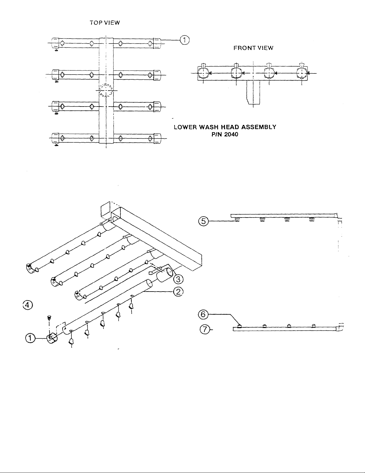
LOWER WASH HEAD ASSEMBLY 8
UPPER WASH ASSEMBLY 8
FINAL RINSE ASSEMBLY 8
SERVICE INSTRUCTIONS (lncoming Water Solenoid Valve) 11
WASH PUMP ASSEMBLY 13
TORQUE-TAMER 22
PAWL BAR ASSEMBLY 26
CAM and CLUTCH ASSEMBLY 28
LOAD SENSOR SWITCH CONVERSION 29
CONVEYOR DRIVE ASSEMBLY 31
LOAD SENSOR SWITCH DETAILS 32
ELECTRICAL DRAWINGS 34
PARTS LIST 38
PARTS DISTRIBUTORS INSIDE BACK COVER
Page 3

SPECIFICATIONS
OPERATING CAPACITY
Racks per hour (NSF Rated) 198
Dishes per hour 5000
Glasses per hour 5000
CONVEYOR SPEED
Feet per minute 5.5
WASH TANK CAPACITY
Gallons 24
WASH PUMP CAPACITY
Gallons per minute 240
THERMOMETER
Wash-°F 140-160
Rinse-°F 180-195
WATER REQUIREMENTS (NSF Rated)
Inlet Temperature °F 180
Gallons per hour 414
Flow pressure PSI 20
Flow GPM 6.9
Inlet-lPS 3/4"
Drain-IPS 1-1/2"
WASH PUMP MOTOR
Horsepower 1
CONVEYOR MOTOR
Horsepower 1/16
ELECTRIC HEAT WASH
KW 13
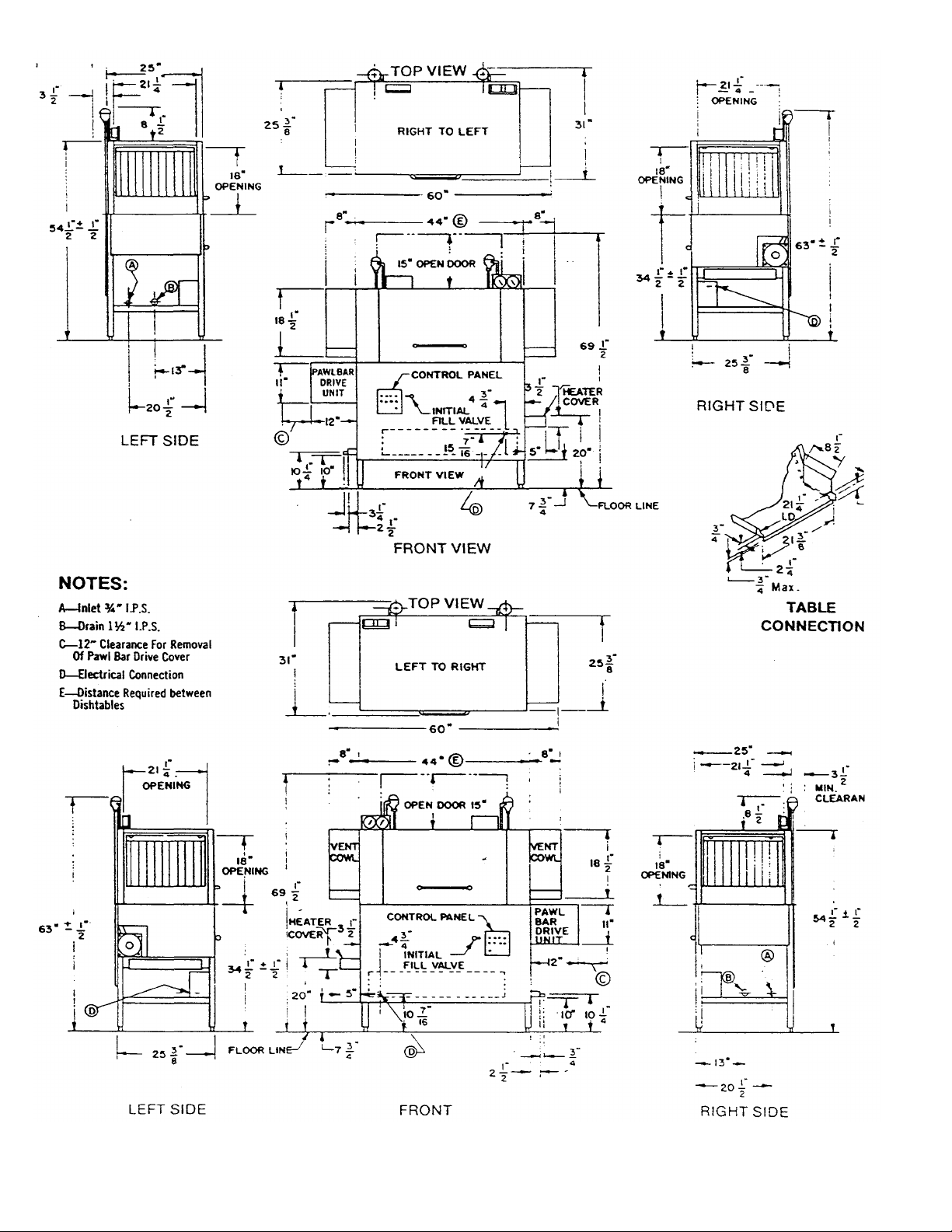
DIMENSIONS
Length (table to table) 44"
Width 25"
Height 55"
Standard table height ± 1/2" 34"
Maximum height for dishes 16"
STANDARD RACKS
Dish 19-3/4x19-3/4 4
Combination 2
SHIPPING WEIGHT BASIC MODELS
(approx.) 600
ELECTRICAL RATING
Volts: 208/220
Phase:1/3
Amps: (approx.)
Specifications subject to change without notice.
Page 4

GENERAL INSTRUCTIONS
(INSTALLATION/DIMENSIONS) for 44CE SERIES
Note: Read the following instructions carefully. Proper installation of your
Jackson Dishwasher will assure proper machine operation.
1. Open the front door (hook open) and remove dish, cup, and glass racks, and set to one side for later use.
Remove the tape holding the overflow strainer, the pump intake strainer, and the wash head assembly
that are inside the machine.
2. Cut straps holding machine to base of crate, ease machine on to floor and slide into place of
installation.
3. Connect drain to bottom of machine (1 1/2" IPS female fitting on bottom of wash sump) with proper slope
to conform with local and/or national codes. Drain is a gravity feed system from machine.
4. Connect incoming 3/4" water line with capacity to supply 6.9 gallons per minute flow, at 20 PSI at a
temperature of 180°F+. This connection is just before the Y-strainer. Connect to conform with local
and/or national codes (STANDARDS).
5. Electrical connections should be made through hole in back of control box to terminal board inside (to the
left lower side of control box). This terminal board is accessible by removing the lower cover plate. The
terminals are marked L1, L2 (requiring 208—230V, single phase), or L1, L2, L3 (requiring 208—230V,
three phase). There is a grounding lug inside of the control box on the bottom left. Be sure all
connections made are tightened properly. Refer to data plate for Voltage and Amperage totals.
6. Install the proper circuit breaker, wire, and conduit size to conform with local and/or national codes. Refer
to data plate for electrical loads.
7. DO NOT APPLY POWER UNTIL STEP 10.
8. Insert pump intake strainer, overflow strainer, runoff sheets, and lower wash manifold, then close door.
9. Turn on hand valve controlling water supply to machine; check for any leaks in plumbing and
connections.
10. To energize electrically, proceed as follows:
a. Turn on customer's circuit breaker controlling machine.
b. Check voltage at incoming terminal L1, L2, and L3 (if applicable). It should match data
plate voltage. Voltage at L1 and L2 should be checked to ground individually to ensure
that a high (or wild) leg is not connected to L1 or L2. (Voltage exceeding 150V to
ground would indicate high leg.)
c. If voltages are in required range, turn on 15 amp circuit breaker. The 15 amp circuit
breaker protects and controls the motors and control circuit only; it is not meant to protect or control
the wash heaters.
d. Insert a rack into the machine, be sure the curtains are in place.
e. Turn the fill handle on the front of the machine to supply the unit with water. It should
take less than four minutes to fill the wash tank. When the desired level is reached turn
the handle back to the original position.
f. Open the front door and check the water level. It should be 1/4" below overflow level. If
not, check the incoming water line making sure that the valve fully opens and closes as
the handle is turned on and off.
g. If the water is the proper level, close the front door and turn on the heat switch. The
heaters are in the wash tank and are utilized to maintain the wash water temperature at
150°.
h. Turn on the conveyor switch. This will set the conveyor pawl bar into motion to pull the
rack of ware through the unit.
i. The unit is now ready to proceed with the washing of dishes in accordance with the
operating instructions in this manual, and the instruction sticker on the front door of
the dishwasher.
Note: As the racks leave the unit do not allow them to accumulate more than three in a row.
Page 5
Page 6

GENERAL INSTRUCTIONS
(OPERATION) 44CE
Note: Read instructions carefully. Proper operation of your Jackson Dishwasher will assure
clean and sanitized glasses and dishes at optimum efficiency.
Dish Preparation
1. Scrape the dishes thoroughly.
2. Pre-rinse the dishes by soaking or by spraying off with a pre-rinse hose.
3. Place the dishes and cups in the dish rack with cups upside down.
4. Place the glasses and silverware in the combination glass-silverware rack with the
glasses upside down. Scatter the silverware loosely on the bottom of the rack. Do not put glasses on top
of the silverware.
NOTE: When silverware is in an upright position, it washes and rinses better than lying flat. These
compartment silverware racks are available through your dealer or service agency.
Machine Operation
1. Open the front door and insert the pump intake strainer, overflow strainer, runoff sheets, and lower wash
manifold.
2. Close the door.
3. Turn the fill valve handle on the front of the unit- It should take less than four minutes for the water level
to reach the top of the overflow. When the desired level is reached turn the handle back to the original
position.
4. Turn on the heat switch, letting the wash temperature reach 150°.
5. Slide in a rack of dirty dishes.
6. Add detergent* (see Detergent Recommendation). If an automatic detergent dispenser is used, follow
the manufacturer's instructions.
7. Start the wash cycle of the dishwasher by flipping the start switch in a up position.
8. To set the conveyor pawl bar assembly in motion flip the conveyor switch in the up position. The pawl
bar assembly automatically pulls the rack through the machine once it enters the opening.
9. When the rack leaves the other end of the machine it should be removed or not allowed to accumulate
more than three racks on the table. This will prevent the clutch from burning out.
10. Once the wash cycle is activated there is no need to turn it off until the end of the meal period. Repeat
steps 6, 8, and 9 for each rack of ware.
11. At the end of a meal period or the end of the day, shut off the heater, wash, and conveyor switch. Drain
the machine by removing the overflow strainer. Clean both strainers, the overflow and the inside
strainer, of all foreign debris and build-up and flush out the unit.
* Detergent Recommendation and Rinse Additives:
We suggest you contact your local detergent specialists for the correct detergent and rinse additives for the
area. To help until one can be reached, we suggest that you use a non-foaming dishwasher detergent,
approximately one-quarter cup in wash tank, when machine is filled the first time, then one level tablespoon
each cycle (or load) thereafter. This may have to be increased or decreased to obtain satisfactory results.
6
Page 7

GENERAL INSTRUCTIONS
(PREVENTIVE MAINTENANCE)
(THE FOLLOWING IS TO BE PREFORMED AS NEEDED.)
Note: Read carefully. Proper maintenance of your Jackson Dishwasher will ensure optimum
1. To remove all lime and corrosion dep osits.
g. Refill as it is ready for regular operation.
2. Clean strainers.
3. Clean Y -strainer on incoming water line. (Water to machine must be turned off for this operation).
a. Remove plug and clean strainer.
4. Clean rinse tubes.
c. If spray holes in the rinse tubes are clogged, they may be cleaned with a pointed tool.
5. Clean wash head assembly.
service with a minimum of down time.
a. Fill the machine with wash water as would ordinarily be done for washing.
b. Open door and place one cup or more of de-liming compound into the water. (Be sure
to follow manufacturer's directions if they vary from these being given) which is
available from your detergent supplier.
c. Turn on wash switch and allow to wash for five minutes.
d. Open door-and examine the interior. All lime should be removed and parts should be
shiny. If not, allow to wash for longer periode. After the interior is clean, empt y the wash water by removing overflow strainer.
f. Replace overflow strainer. Refill machine and allow to run for two minutes, then, again
drain the wash reservoir.
a. Clean around overflow and pump intake strainer holes.
b. Clean around pump intake (toothbrush makes excellent tool for cleaning).
a. Remove end plugs on lower and upper rinse.
b. Clean all rinse tubes with special brush supplied.
a. If spray jets are plugged, use pointed tool to dislodge and flush with water.
b. If lodged items still remain in wash tubes, remove wash assembly by first removing
rinse assembly.
c. Clean assembly at sink by flushing water through spray jets. d. Reinstall wash and rinse
assemblies. (See page with instructions).
6. Clean any deposits which may have built up on exterior moving parts.
7
Page 8
UPPER WASH ASSEMBLY
P/N 1990
ITEM P/N DESCRIPTION
1. 2035 WASH HEAD TUBE CAP
2. 2020 WASH HEAD TUBE
3. 2025 WASH HEAD SPRING CUP
4. 2030 WASH HEAD SCREWS
0203700 TUBE CAP W/"O" RING
FINAL RINSE ASSEMBLY
P/N 6137500
ITEM PIN DESCRIPTION
5. 1390 RINSE ASSEMBLY UPPER NOZZLES
6. 1395 RINSE ASSEMBLY LOWER NOZZLES
7. 1400 RINSE ASSEMBLY END PLUGS
8
Page 9
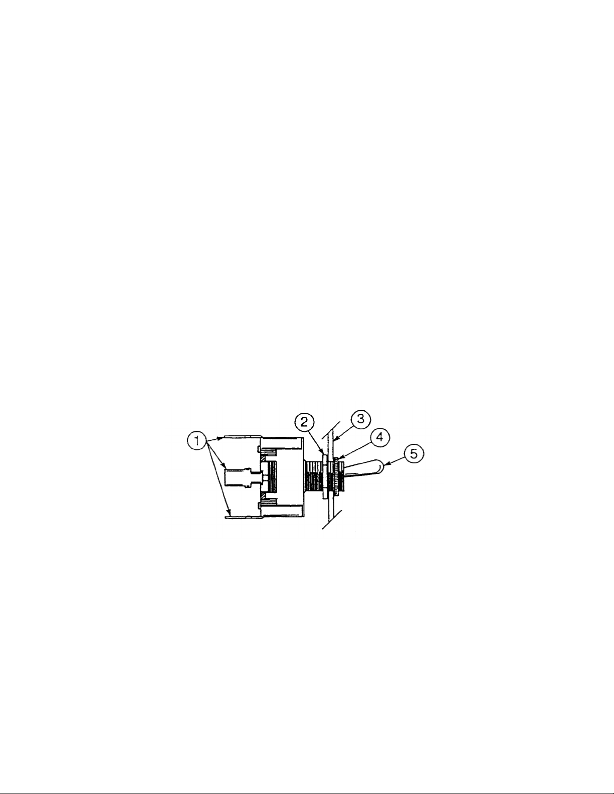
REPLACEMENT of SWITCHES In
CONTROL PANEL
There are three switches installed in the control box cover panel. These are the conveyor, wash, and
heater switches.
Before working on machine, it is important that power be turned off at customer's circuit breaker to prevent
the possibility of electrical shock, trip breaker to "off" position. Then turn machine breaker "on" located right
side of control box.
Remove the control panel from the control box. The three switches are mounted in individual round holes
with a keyway. By using a pair of pliers or open end wrench, it is possible to loosen the inside nut enough
to allow the outside nut holding the switch to be removed by fingers. Push switch out of hole.
If a switch is found to be defective, replacement can be achieved by placing the new switch next to the old
one. To make sure the new switch is not upside down, line up with the keyways. Transfer wires one at a
time to the new switch. If this is not practical, pull wires off, one at a time and tag them for proper
replacement.
Put switches back into panel, make sure switch protrudes through panel properly, tighten both nuts, and
replace control panel on control box. Power can now be applied to dishwasher and run through cycles
checking all operations.
P/N 1575
1. CONNECTION TERMINALS
2. INSIDE NUT
3. PANEL PLATE
4. OUTSIDE NUT
5. BAT OR TOGGLE HANDLE
9
Page 10
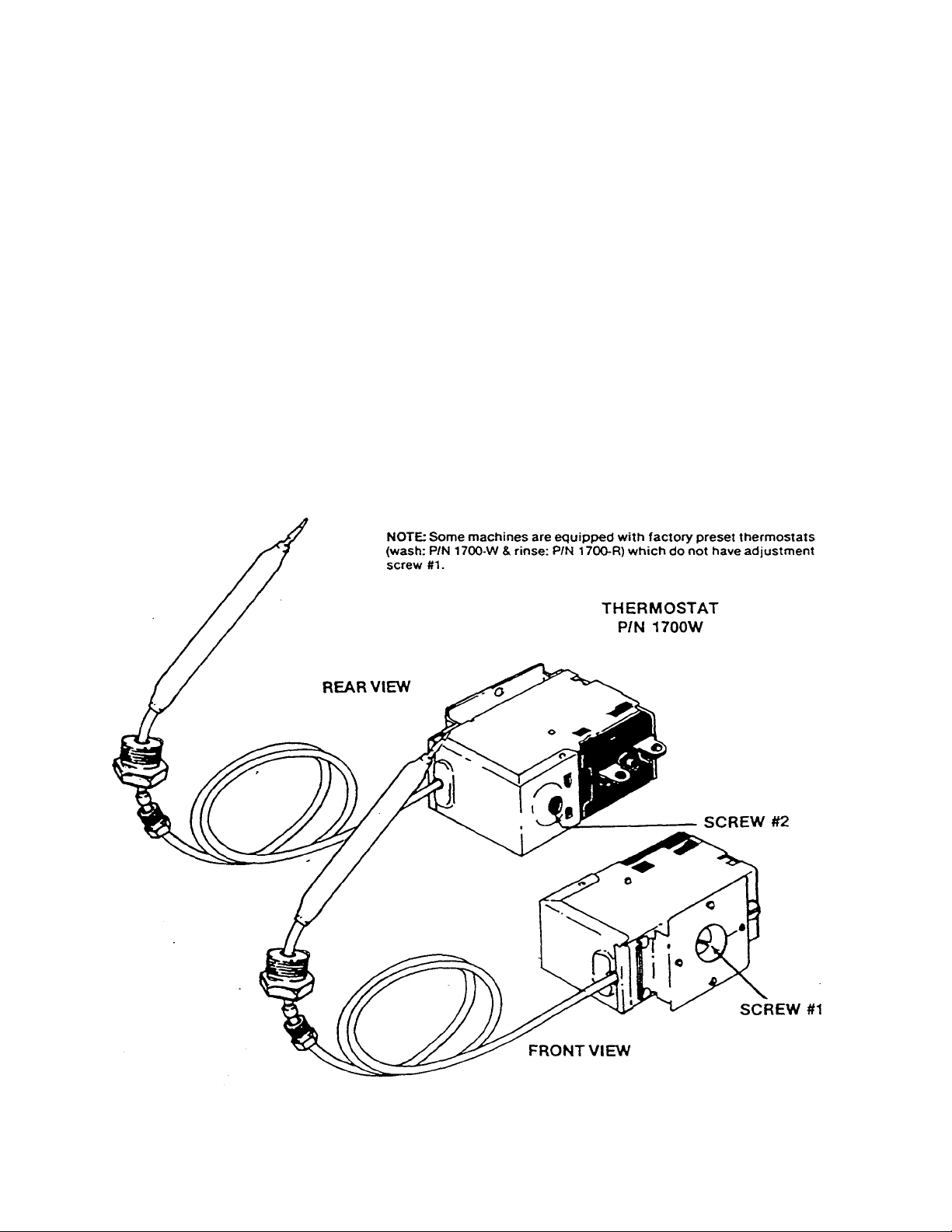
THERMOSTAT ADJUSTMENT
The thermostat can be adjusted by turning screw #1 (see picture) on the thermostat control box cover.
(Remember the present setting, in case the problems are elsewhere in the control circuit). A CW rotation
is used to obtain a lower temperature setting and a CCW rotation is used to obtain a higher temperature
setting. A 1/8 turn of screw #1 changes the temperature approximately 15°F. If screw #1 is turned all the
way to its stop in either direc tion; adjust screw #2 as follows. DO NOT TOUCH THE SCREW SEALED
WITH RED PAINT. When adjusting screw #2 power should be disconnected during adjustment.
Set screw #1 so that it can be turned-equal distances in either direction, then:
— if screw #1 stopped while turning in CW direction, turn screw #2 in CW direction slowly and only
1/8 of a turn or less per complete cycle of the unit.
— if screw #1 stopped while turning in CCW direction, turn screw #2 in CCW direction slowly and
only 1/8 of a turn or less per complete cycle of the unit.
Three-fourths of a turn will bring the thermostat to approximately the same setting obtained where
screw #1 stopped. Check the present temperature setting before attempting any further adjustments.
Use screw #1 for any further adjustments.
NOTE: Making large moves in adjusting may cause misalignment thus increasing
the chances that further adjustment cannot be made and the thermostat
will have to be replaced.
10
Page 11
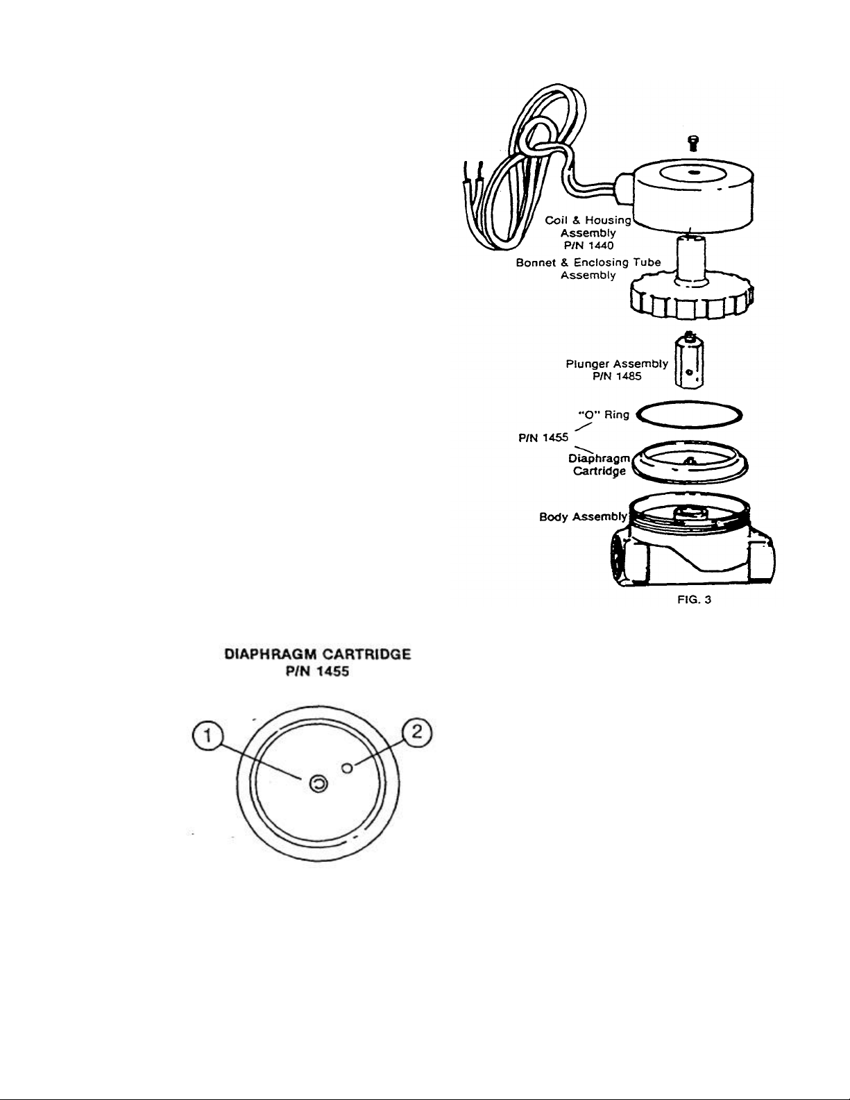
SERVICE INSTRUCTIONS
(INCOMING WATER SOLENOID VALVE)
To Take The Valve Apart
Disassembly - These valves may be taken apart by unscrewing the
bonnet and the enclosing tube assembly from the valve body assembly.
See Fig. 3. After unscrewing, carefully lift off the bonnet and enclosing
tube assembly. Don't drop the plunger. The "0" ring seal and diaphragm
cartridge can now be lifted out.
Be careful not to damage the machined faces while the valve is apart.
To Reassemble - Place the diaphragm cart ridge in the body with the
pilot port extension UP. Hold the plunger with synthetic seat against the
pilot port. Make sure the "0" ring is in place, then lower the bonnet and
enclosing tube assembly over the plunger. Screw bonnet assembly
snugly down on the body assembly.
11
Possible Problems
Pilot Port extension #1 clogged
Hole #2 clogged
Remedy
Pass heated straight pin through hole #2 or
clean hole #1
Page 12

REPLACING SEAL and CERAMIC
on WASH PUMPS
Function:
The pump is part of the total motor-pump system and utilizes one shaft seal and ceramic to prevent the
pump from leaking around the impeller and shaft. One gasket is used to prevent leakage between the
pump mounting plate and the machine pump plate.
Replacement of Seal and/or Ceramic:
1. Remove the power source to the machine by turning the circuit breaker to its "off" position on the side of
the control box.
2. Drain the machine by removing the overflow strainer in the wash tank.
3. Support the motor—remove the four nuts holding the pump/motor to the machine's pump plate.
4. Carefully pull motor outward, move from side to side as required to remove from machine.
5. Set motor and pump on a sturdy stand clos e to machine or remove wires and conduit to allow
motor/pump to be moved to a better work station.
6. Insert a firm object into the blades of the fan and use 1 5/16" ratchet to remove bolt holding impeller.
After the bolt is removed, pull the impeller up and off of the shaft.
7. The ceramic is imbedded in the pump mounting plate and usually does not need
replacement, but the seal normally would when water leaks around the motor shaft area.
If replacement of either is required, proceed as follows:
a. Remove the four bolts holding the pump mounting plate to the motor.
b. Slide the mounting plate up and off of the shaft and motor. The imbedded ceramic and shaft seal will
be removed with the mounting plate.
c. Turn over the plate and push the seal and/or ceramic out of the housing carefully. It may be
necessary to break the ceramic to remove it.
d. Clean the hole where the ceramic was installed.
e. Lightly coat with a lubricant around the new ceramic's edges and "0" ring. Gently press the ceramic
into place against the snap ring in the housing. Make sure that the grooved side of the ceramic faces
the motor and housing snap ring, leaving the smooth side toward the impeller.
f. Make sure that the woodruff key is in place in the shaft and then set the plate back
on the motor over the shaft.
Note: A field tool can be made (to ease installation of seal) from a pipe or tube (3/4" CPVC
typical example) that has proper outside and inside dimensions. It must fit over step
down in shaft, but be close to larger shaft size on outside - To accommodate woodruff,
cut long slot in tube. Lubricate tube slip seal over tube onto shaft.
g. Lightly coat with a lubricant the new seal face and gently press it into place over the shaft with seal
face against the ceramic. SEE NOTE ABOVE.
h. Place the spring over the shaft with the metal cap up. Press the impeller down onto the shaft, aligning
the keyway of the impeller with the woodruff key.
i. Tighten the impeller washer, lockwasher, and bolt into place. Replace the four bolts that hold the
mounting plate to the motor.
8. Reinstall the pump and motor in the unit by reversing steps one through eight (it is suggested that a new
pump gasket be installed).
Impeller Rotation:
When facing the impeller after mounting it on the motor shaft, the impeller should turn in a CCW
direction.
12
Page 13

3.
WASHER, RUBBER
ITEM P/N DESCRIPTION
1. 1027 PUMP MOTOR
2. 1065 WOODRUFF KEY
4. 1080 SNAP RING
5. 1050 CERAMIC FACE W/"O" RING
6. 1045 PUMP MOUNTING PLATE
7. 1050 SEAL FACE
8.
9. 1050
10. 1055 PUMP IMPELLER
11. 1075 IMPELLER WASHER
12. 1070 IMPELLER BOLT & LOCKWASHER
13. 1060 PUMP MOUNTING GASKET
PLATE TO MOTOR MOUNTING BOLTS &
LOCKWASHERS
SEAL ASSEM BLY (SEAL SPRING & CUP
WASHER)
13
Page 14

TROUBLE SHOOTING GUIDE
Temperature readings not within required
Spray tubes clogged with paper towels, toothpicks,
any obstructions in the pump intake hole,
The information contained herein is intended to help you solve some problems that may exist on your dishwasher from time to time.
Anything not covered in this guide should be referred to the factory. References to section drawings within this book will be made
throughout this "Trouble Shooting Guide." Refer to these section drawings to help you in correcting the problems.
PROBLEM CAUSE SOLUTION
1. Check thermometer by using a
range.
1. Thermometer is defective.
thermometer known to be accurate. If
defective, replace.
Final Rinse switch
Washing action does not get dishes
clean.
2. Heat switch contactor, elements, thermostats,or
low-water level control.
1. Refer to incoming water and rinse section for
solution.
1.
etc.
2. Pump intake strainer clogged.
3. Scrap basket full; will not allow water to return to
tank.
4. Overflow and drain tube not solid in drain fitting,
not allowing pump sufficient water, for pumping
action.
5- Pump clogged.
2. Refer to bottom drawing and electrical
drawing.
1. Remove upper spray tubes and clean,
remove lower assembly and clean
spray tubes by removing tube caps.
2. Remove pump intake strainer and
clean.
3. Remove scrap basket and clean.
4. Remove overflow and drain tube and
replace solidly in drain fitting.
5. With pump intake strainer off, check. If
remove.
Water in wash tank
excessively high.
Pawl bar not operating to push dishes
through dish washer.
Unable to maintain heat in wash tank.
6. Pump impeller not turning; therefore, motor is not
turning and pumping.
1. Overflow and drain tube clogged or covered with
napkin, etc.
1. Something jammed between pawl bar and clean
dish side of dishwasher.
2. With pawl bar removed, drive rod doesn't
operate.
1. Water too low in wash tank and does not touch
probe.
2. Low-water cutoff system not operating. (Probe is
part of this system.)
14
6. Refer to Pump/Motor Section.
1. Drain tank and refill to ensure clean
water.
1. Remove obstruction.
2. Check section "Conveyor Drive
and Motor."
1.Turn fill valve on refill machine (make
sure overflow and drain tube are
securely in drain).
2. Refer to "Electrical Section Drawing."
Read Electrical Checkout.
Page 15

TROUBLE SHOOTING GUIDE
Rinse temperature not within required
solenoid valve according to instructions
Rinse trip assembly is not tripping final rinse limit
dishwasher and make sure there are no
obstructions and no extreme number of
PROBLEM CAUSE SOLUTION
3. Thermostat not functioning properly. 3. Follow 6A.
4. Heaters not functioning. 4. Follow 6A.
Vacuum breaker is allowing water to
escape and spray on top of machine
and against wall.
range.
Little or no water coming from final
rinse nozzles when machine is in
operation.
1. Vacuum breaker is defective.
2. Gasket on poppet split or worn.
1. See "Top Section" for correction action.
1. 3/4" solenoid valve not opening to allow flow of
water.
2. Final rinse limit switch faulty.
3.
switch.
4. Water on incoming plumbing supplied by
customer not sufficient.
1. Remove top of vacuum breaker by
unscrewing. Lift poppet out and clean.
2. Replace rubber gasket and washer on
poppet completely.
1. Dismantle, clean and check out
on solenoid sheet Replace solenoid if
necessary.
2. Check switch to see that it has
continuity when in "on" position, if not
replace.
3. Make sure that coupling between
vertical rod from final rinse paddle is
tight and turns final rinse limit switch, if
not tighten. If vertical rod is bent,
straighten.
4. Check flow of water. If water isn't
sufficient, check line coming to
branches off from this line that could
steal water.
Can't fill machine. 1. Water to machine not turned on. 1.Tum water supply on.
5. Rinse nozzles clogged.
15
5. Unscrew rinse nozzles and clean. With
nozzles out, activate machine to see if
good amount of water flows. If not,
check plumbing.
Page 16

ring in
re
getting power into the switch and out of
se connections
TROUBLE SHOOTING GUIDE
PROBLEM CAUSE SOLUTION
Wash tank runs out of water. (This is
covered on previous page and is
continuation.)
Final rinse catch basin overflowing. 1. Crumb cup in drain clogged. 1. Remove crumb cup and clean.
Water level too high or low in wash
tank.
Pawl bar moves with no load but does
not move when loaded.
Pump/motor doesn't run. 1. Wash motor switch is defective.
Conveyor motor doesn't operate. 1. Conveyor push button switch is defective.
1. 1/4" Solenoid valve not operating.
2. Final rinse limit switch is defective.
1. Check previous Section for solution.
2. "O" ring not in drain fitting or damaged.
1. Clutch slipping.
2. Loose wires or connections.
3. Pump jammed.
1. Check Solenoid valve to see that it is
operating, if it doesn't operate, replace.
2. Check final rinse limit switch out to see
if it has continuity across the normally
closed contacts. If not, replace switch.
2. Check to see that there is an "0"
the drain fitting and it is not damaged.
Replace if necessary.
1. Adjust clutch. (See page insert for
instructions of Torque Tamer).
1. With switch on, check to see that you'
the switch, check back to circuit
breaker on dishwasher. If you are, but
not out of the switch, replace switch.
2. Check all wiring to and from motor to
see that there are no loo
or broken or frayed wires. Repair or
replace as necessary.
3. See previous instructions "Bottom
Section."
1. Check to see that power is going into
the switch for the conveyor and is
coming out the other side or turn off
power and check the continui ty by
pushing switch in and out to see that it
does turn the system on and off. If
switch's defective, replace.
16
Page 17

TROUBLE SHOOTING GUIDE
thermostat up or down as needed. If this
sulated wire, short
pass
level control have power coming to them,
If low water control is operating, the contacts
PROBLEM CAUSE SOLUTION
Heat circuit does not operate (wash
tank not at required temperature).
2. Loose wires or connection.
3. Motor is defective.
1. Water level in wash tank below low-water cutoff
probe.
2.Thermostat is out of adjustment or defective.
2. Check all wiring for breaks, loose
terminals and connections, and repair
accordingly.
3. Motor hums or doesn't operate at all.
Defective, replace motor.
1.FiII wash tank to overflow level.
2. By turning adjustment screw, adjust
doesn't increase or decrease the heat,
with a small piece of in
the two terminals on the thermostat out
with the heat switch on. This will by the thermostat action and if the water
temperature rises, the thermostat is
defective and should be replaced.
3. With heat switch on, check to see that
the terminals L1 and L2 on the water-
3. Water level control is defective.
4. Water-level control checked out okay on 9C, but
heat circuit still does not operate.
17
then with a short link of insulated wire.
Jump terminals 'L' and 'H'. These
terminals are on the low voltage (24V)
system.
in the little plastic-coated relay will work or
move. (Before attempting above, remove a
wire to Water-level probe).
4. Make sure that the probe wire has been
replaced.
Page 18

Item No. P/N DESCRIPTION
1. 453 CURTAIN
2.
3.
4.
5.
6. 1635
1691 WASH THERMOMETER
1377A RINSE ACTUATOR HELPER SPRING
1378 RINSE ACTUATOR COUPLING
1377B RINSE LIMIT SWITCH BRACKET
1636 RINSE LIMIT SWITCH
ITEM P/N DESCRIPTION
7. 1692 RINSE THERMOMETER
8. 526 DOOR FRONT CATCH
9. 1379 RINSE ACTUATOR ROD BRACKET
10. 1376 RINSE ACTUATOR PADDLE & ROD
11. 844 PROBE COVER
12. 525 FRONT DOOR
13. 530 FRONT DOOR HANDLE
18
Page 19

ITEM P/N DESCRIPTION
1. 1700 THERMOSTAT
2. 605 WASH TANK HEATER (6 EA.)
3. 843 LOW WATER PROBE
4. 1805 BACK CONVEYOR TRACK
5. 1410 LARGE RUNOFF SHEET
6. 1405 SMALL RUNOFF SHEET
7. 425 CONVEYOR PAWL BAR ASSEMBLY
8- 2035 WASH HEAD TUBE CAP
9. 2020 WASH HEAD SPRAY TUBE
19
ITEM P/N DESCRIPTION
10. 2025 WASH HEAD SPRING LOCK
11.
12. 2040 WASH HEAD MANIFOLD COVER
13. 1530 LARGE OVERFLOW TUBE
14. 1525 PUMP INTAKE STRAINER
15. 1535 TRACK & SCRAP STRAINER ASS'Y
16. 1790A FRONT TRACK LARGE SECTION
17. 1790B FRONT TRACK SMALL SECTION
TRANSFER SHEET
Page 20

ITEM P/N DESCRIPTION
1. 1414 DRAIN CRUMB CUP
2. 1530 OVERFLOW TUBE
3. 540 DRAIN "O" RING
21
ITEM P/N DESCRIPTION
4. 0002826 WASH DRAIN FITTING
5.
DRAIN OUTLET 1 1/2" IPS
Page 21

TORQUE-TAMER
clutch
FACTORY SERVICE BULLETIN #91
Model: 44 Clutch Adjustment
A.) Drive Bar Clearance Adjustment:
This instruction should be used to adjust the conveyor drive clutch, should the following problems arise:
1.) Cam follower bearing requires replacement due to damaged or broken stud
2.) Cam follower bearing jumps out of the slot in the drive arm and jams the drive system
Instructions (Refer to Figure I):
1.) Check the clearance between the top of the cam wheel and the drive arm. This clearance should be
1/32" or less, but also should not bind. If the clearance is more than 1/32", the following steps should
be performed:
a.) Measure the clearance between the top of the Cam Wheel and the drive arm, and between the
bottom of the clutch and the shoulder on the motor shaft.
b.) Remove Drive Motor from unit or pivot downward.
(This can most easily be accomplished by removing three of the motor mounting plate bolts &
allowing the motor assembly to pivot on the fourth bolt.)
c.) Remove Cam Wheel by loosening (3) allen head screws and lifting off.
d.) Loosen set screw at top of clutch.
e.) Remove clutch assembly from shaft.
f.) Place the proper combination of spacer washers on the shaft that will be equal to (or up to 1/32"
less than) the total of the clearances measured in step (a.).
NOTE: If cam follower bearing needs to be replaced, apply "Loctite 242" (or equiv.) to threads of
the new bearing. Tighten bearing securely and tighten locking set -screw. (Do not use
"Loctite" on the set -screw.)
g.) Replace clutch assembly on shaft, making sure that clutch assembly bottoms out on
the spacer washers.
h.) Retighten set -screw.
i.) Replace Cam Wheel
j.) Replace motor on unit and check clearance.
k.) Repeat, if necessary, until proper clearance is obtained.
22
Page 22

3.) Torque Adjustment:
This instruction should be used to adjust the conveyor drive clutch, should the following problems arise:
1.) Excessive slippage of clutch, resulting in racks not being pushed through machine.
2.) Damage to cam follower bearing or other conveyor drive parts due to clutch not slipping when
jammed or overloaded.
Instructions (Refer to Figure II):
1.) Loosen the three tension screws at least three turns. (They should not protrude through the adjusting
nut.)
2.) Loosen the adjusting nut set-screw at least six turns.
3.) To obtain initial setting, turn the adjusting nut by hand as tightly as possible — do not use a tool. Now,
back the adjusting nut off (counter-clockwise) one and one-half (1 1/2) turns — this will correspond to
nine notches. Tighten set -screw into closet spline notch at this location.
4.) Retighten the three tension screws - The tension screws should be tightened alternately and evenly
until heads bottom.
5.) Check torque adjustment again by exerting hand pressure against the rack. It should slip only under
heavy pressure such as a jam; however, it should move at least three heavily loaded racks without
slipping.
6.) If necessary repeat steps 1 & 2 and readjust adjusting nut as required — rotating the nut one notch
only (CCW to loosen, CW to tighten). Continue with steps 4, 5, & 6.
23
Page 23

FACTORY SERVICE BULLETIN #97
Clutch Conversion For
Series-44 Conveyor System
This conversion is to be used on all 44-Series units that develop recurring conveyor drive problems due to
breaking-off or stripping-out of the cam follower bearing. (For machines with persistent problems, it is
recommended that this conversion be performed in conjunction with Factory Service Bulletin #96.) Tools
Required:
Wrench Set
Hex Key Wrench Set
Torque Wrench, 3/8" drive, 30-200 Ib-in, ("Snap-on" #QC-217 or equiv.)
Crowfoot Wrench, 1 1/4" x 3/8" drive, ("Snap-on" #FC-40 or equiv.)
Tube or bottle of "Loctite 242" or equiv.
Parts Required:
(1) - Drive Hub
(1)- Friction Plate
(1)- Shaft Extender
(1)- Motor Riser
(1) - Torque Limiter Assembly
(1) - Cam Follower Bearing
(1) - "Oilite" Bearing
(1) - 3/8 - 16 x 1 1/4" long Hex Socket Head Cap Screw
(3) - 10-32 x 1 1/ 4" long Hex Socket Head Cap Screws
(1) - Locknut (thin series) 5/16-24NF
Procedure:
1.) Disconnect power to machine.
2.) Remove cover from conveyor drive assembly.
3.) Remove bolts that hold gear-motor riser to machine frame and lower gear-motor assembly away
from drive assembly.
4.) Remove motor riser from gear-motor and discard.
5.) Install new motor riser with four outer holes positioned closer to top, us ing existing hardware.
6.) Remove clutch and cam wheel assembly from gear-motor shaft and discard.
7.) Assemble clutch and drive hub assembly as per (Figure I.). Use "Loctite 242" or equiv. on cam
follower lock nut (be sure to remove all grease from screw threads first). Tighten all hardware, except
clutch adjustment nut, securely.
8.) Remount gear-motor assembly on machine frame, using existing hardware.
9.) Loosen setscrews in clutch adjustment nut so that nut turns freely.
10.) Using torque wrench with crowfoot adaptor, carefully adjust nut to a torque reading of: 30 in-lb.
11.) If machine is equipped with a "load sensor" switch, temporarily defeat this switch with a jumper wire
to facilitate adjusting the clutch.
12.) Jam conveyor drive bar by placing a piece of 2" x 4" between pawl bar support and machine wall
(with the conveyor OFF). Turn conveyor on and allow clutch to slip for at least 3 minutes "to burn in"
the clutch surfaces. (Note: if thermal overload cuts out during this period, allow time to cool and reset
in order to accumulate the total time required.)
13.) Allow clutch to cool and carefully reset with torque wrench to 30 in-lb. Clutch should not slip unless
jammed as in step #12. If further adjustment is required, make changes in 5 in-lb. increments and
recheck. Securely tighten the setscrews after attaining the final set ting.
14.) Test again to make sure clutch will still slip when jammed.
15.) If machine is equipped with a "load sensor" switch, remove the jumper wire installed in step #11.
Test to verify that switch will now stop drive motor before clutch slips, when drive bar is jammed.
16.) With machine turned off, replace all covers and hardware.
24
Page 24

25
Page 25

ITEM P/N DESCRIPTION
1. 450 PAWL BAR DOG STOP
2. 430 PAWL BAR PAWL (DOG)
3. 447 PAWL BAR NUT (NYLON INSERT)
4. 112 LOCK WASHER 1/4 X 20 S/S
5. 435 PAWL BAR SPACER PIN
6. 440 PAWL BAR SPACER BUSHING
7. 445 PAWL BAR CONNECTOR PIN
8. 446 PAWL BAR BOLT 1/4" X 20 X 3/4" S/S
9. 0003534 PAWL BAR SIDE RAILS
10. 0113283 PAWL BAR W/ ULTRA WEIGHTS
26
Page 26

ITEM P/N DESCRIPTION
1. 390 CLUTCH ADAPTER PLATE
2. 370 CAM WHEEL SET SCREW
3. 365 CAM WHEEL
4. 380 CAM FOLLOWER BEARING
5. 353 DRIVE ARM
6. 410 SHOULDER SCREW 1/ 4"
ITEM P/N DESCRIPTION
7. 355 ARM LINKAGE
8. 405 ROD WIPER
9. 400 DRIVE ROD BEARING
10. 360 DRIVE ROD ARM
11. 345 DRIVE MOTOR AND GEAR HEAD
27
Page 27

ITEM P/N DESCRIPTION
1-9 385 DODGE TORQUE TAMER #25
10. 415 10-24 X 3/8" LONG SET SCREW
11. 380 CAM FOLLOWER BEARING
12. 422 3/16" KEY
13. 350 SHAFT ADAPTER
14. 395 BUSHING .879" 00 X .752" ID
15. 365 CAM WHEEL
16.
17. 39001 CLUTCH ADAPTER PLATE
CAM AND CLUTCH ASSEMBLY
10-32 X 7/16" MACH. SCREW
28
Page 28

FACTORY SERVICE BULLETIN
#96
"Load Sensor" Switch Conversion
(FOR SERIES 44 CE & 44CL CONVEYOR SYSTEM)
This conversion is to be used on all 44-Series units that develop recurring conveyor drive problems due to
overloading or Jamming of the system.
Tools Required:
Wrench Set
Hex Key Wrench Set
3/8" Electric Drill
Drill Bits, sizes: 9/64, 13/64, & 9/32
1/4 - 20 Tap and Tap Handle
Center Punch
7/8" Greenlee Chasses Punch (May be needed, if additional conduit hold is required.)
Screwdrivers - Slotted & Phillips
Wire Strippers
Terminal Crimping Tool
Tube or Bottle of "Loctite 242 " or equivalent
Template for locating hole centers
1/4" Nut Driver
Parts Required:
(1) Actuator Assembly
(1) Switch, flange mounted
(1) Connecting Link
(2) Bushings (1) Clevis Pin (1) Cotter Pin (4) Spring Washers
(1) Shoulder Screw, ss (8') 3/8" Flexible Conduit (20') Wire, 18ga.,red (ea.) Assorted Terminals
(2) #8 Hex Head Sheet Metal Screws (2) 3/8" Straight Conduit Fittings
Procedure:
1.) Disconnect power to machine.
2.) Remove cover from conveyor drive assembly.
3.) Remove the drive rod arm, linkage, and linkage bracket (see Fig. I). Discard the linkage and linkage
bracket.
4.) Remove the drive rod support bracket.
5.) Using the 1" diameter hole in the base plate as a reference, center punch the hole locations for the
four new holes. (The use of the hole template is recommended.)
6.) Drill two 9/64 diameter holes, one 13/64 diameter hole, and one 9/32 diameter hole as shown. Top
the 13/64 diameter hole with a 1/4 - 20 tap.
7.) Replace the drive rod support bracket.
8.) Connect wires to the COM and NO terminals of switch (using ring terminals) and connect conduit to
switch with straight connector.
9.) Mount switch to base plate, using two #8 sheet metal screws.
29
Page 29

10.) Mount actuator to base plate, using spring washers and shoulder screw (as shown in Fig. 111). NOTE:
SPRING WASHERS MUST BE INSTALLED EXACTLY AS SHOWN FOR PROPER OPERATION. USE
LOCTITE ON THREADS OF SHOULDER SCREW—IF OIL WAS USED WHEN DRILLING OR TAPPING % 20 HOLE, REMOVE ALL TRACES BY USING A SOLVENT CLEANER.
11.) Assemble connecting link to actuator assembly by using spacers, clevis pin, and cotter pin, as shown.
12.) Reinstall drive arm, making sure all parts are in proper alignment without binding, etc.
13.) Route other end of conduit and wire into main electrical box of machine. (If all 7/8" diameter hole
openings are used up, an additional one will have to be added.)
14.) Connect switch wiring in main electrical box as per appropriate wiring diagram (i.e." Model 44CE or
44CL).
15.) Replace all electrical covers.
16.) Turn on power to machine.
17.) Test operation of load sensor by:
a.) Jamming conveyor drive bar by placing a piece of 2" by 4" between the pawl bar support and
machine wall (with the conveyor OFF). Turn conveyor on—it should stop immediately upon
binding, and before clutch slips. (If clutch slips first, it needs adjustment.)
b.) Test conveyor for normal operation. It should transport at least three loaded racks
under normal conditions without cutting out. if switch cuts out prematurely, check the 2 21/32
measurement of the actuator arm (see Fig. Ill) and bend as required; however, if this is
necessary, REPEAT STEP 17-a.)
18.) With machine turned OFF, replace all covers and hardware.
30
Page 30

CONVEYOR DRIVE ASSEMBLY
31
Page 31

"LOAD SENSOR" SWITCH DETAILS
32
Page 32

WIRING OF "LOAD SENSOR" SWITCH CIRCUIT
MODEL 44CE
33
Page 33

Page 34

Page 35

Page 36

Page 37

COMPLETE PARTS LIST for MODEL
44
120 Circuit Breaker, 15 amp (specify number from Part)
194 Control Box comp. wired
195 Control Box comp. wired
345 Conveyor Drive Motor 115/230V, 1/6HP; 29 rpm output
350 Conveyor Drive Shaft Adaptor, for motor
353 Conveyor Drive Arm
355 Conveyor Drive arm linkage 479-AD2922
360 Conveyor Drive rod arm 477-BA2914
365 Conveyor Drive cam wheel 549-AD3069
370 Conveyor Drive set screw, cam wheel
375 Conveyor Drive bolts, cam wheel socket head screw
380 Conveyor Drive cam follower bearing
385 Conveyor Drive clutch, torque tamer
390 Conveyor Drive clutch adaptor plate 550-AD-3070
395 Conveyor Drive bushing for cam wheel
400 Conveyor Drive bearing, for drive rod
405 Conveyor Drive wiper, for rod
410 Conv eyor Drive shoulder screw, 1/4"
415 Conveyor Drive shoulder screw, 3/8"
417 Conveyor shoulder bolt, 1/2"
420 Conveyor Drive shoulder screw, 3/4"
422 Conveyor Drive Key 554-BA3117M
423 Conveyor Pawl Bar Idler Roller
424 Conveyor Pawl Bar Idler Roller Bushing
425 Conveyor Pawl Bar assembly
429 Pawl Drive Connector Pin
430 Conveyor Pawl Bar pawl (dog)
435 Conveyor Pawl Bar spacer pin
440 Conveyor Pawl Bar spacer bushing
445 Conveyor Pawl Bar connection pin
446 Conveyor Pawl Bar bolts
447 Conveyor Pawl Bar nut (nylon insert)
450 Conveyor Pawl Bar dog stop
451 Conveyor Cutoff Switch KIT (table mount) w/ instructions
452 Curtain rod
453 Curtain
525 Door, front
526 Door, front catch
530 Door handle, front
540 Drain 'O' ring
560 Gauge, pressure, 0-60, bottom connection
587 Heater socket ONLY for heater element removal screw plug type
588 Heater bus bars, 3 hole
589 Heater bus bars, 2 hole
605 Heater element. Immersion, screw plug type, 230V, 2500W
608 Element for hard water application 220V, 2180W
835 Light indicator
843 Probe, Lundy, Small
1020 Pump assy. comp. JET 1 HP 1725 rpm 115/208-230V
1025 Pump motor, JET, 100/200V, 1 HP 1725 rpm w/adapter shaft (use 1027
1026 Pump motor ONLY, JET Special 1 HP 1725 rpm 220V 50 cycle for JL 100
1027 Pump motor, 1 HP 1725 rpm 115/208-230V
1030 Pump motor, JET, 115/230V, 1 HP 1725 rpm w/ adapter shaft
1035 Pump adapter shaft (for parts 1020; 1025; 1030)
1036 Pump motor bearing front (368C034H 63)WH
1037 Pump motor bearing rear (368C945H 19)WH
1040 Pump rolled pin (for parts 1020; 1025; 1030)
1045 Pump mounting plate (for part 1020)
1050 Pump seal and ceramic (for part 1020)
1055 Pump impeller (for part 1020)
1060 Pump gasket, (for part 1020) (mounting)
0087812 Pump Seal, New Style
Page 38

COMPLETE PARTS LIST for MODEL
44
1065 Pump, Woodruff Key (for part 1020)
1070 Pump bolt, Impeller, s/s 5/16-1" (for part 1020)
1075 Pump washer, Impeller (for part 1020)
1080 Pump snap ring (for part 1020)
1180 Rack, Square (dish) moulded w/conveyor rungs
1182 Rack, Square (cup, bowl & glass) moulded w/conveyor
1210 Relay, 220V, 2-pole HW (used on motor circuits)
1230 Relay, 220V, 3-pole, HW (used on heat circuit, three phase)
1240 Relay. 220V, 4-pole, HW (used on heat circuit, single phase)
1247 Relay Overload (for conveyor motor) w/heaters
1375 Rinse head assembly, final, complete
1376 Rinse Actuator Paddle and Rod
1377 Rinse Actuator Rod Bushing
1377A Rinse Actuator Helper Spring
1377B Rinse Limit Switch Bracket
1378 Rinse Actuat or Coupling
1379 Rinse Actuator Rod Bracket
1380 Rinse assembly, final, upper
1381 Rinse Actuator Assembly w/o Switch
1382 Rinse Actuator Assembly w/Switch (Specify Direction)
1385 Rinse assembly, final, lower
1390 Rinse Spray nozzles, final, upper
1395 Rinse Spray nozzles, final, lower
1400 Rinse End Plugs, 1/2" pipe plugs
1405 Runoff sheet, small
1410 Runoff sheet, large
1414 Crumb cup assy. for drain on tables and 44CE
1417 1/8" Asco Detex BX
1419 Asco valve, 1/4", 220V
1525 Strainer, pump intake
1530 Strainer, large overflow tube
1535 Strainer, track scrap, large
1537 Strainer, 'Y', ¾”
1539 Switch boot or cover (used on 10; 50; JL & some 39's)
1540 Switch, rinse/fill (All) (SPDT) momentary slip disconnect
1555 Switch, manual wash (DPDT) (All) slip disconnect
1575 Switch, master (DPST) (All) slip disconnect (used on wash, heat & conveyor on 39's)
1635 Switch, limit (final rinse) L/R machine
1636 Switch, limit (final rinse) R/L machine
1691 Thermometer, 3' long capillary, 2" dial
1692 Thermometer, 6' long capillary, 2" dial
1700W Thermostat, wash, 150°
1702 Thermostat, longer capillary
1790A Track, Front Large Section
1790B Track, Front Small Section
1805 Track, front and back
1848 Handle for 1/2" fill valve (complete) specify direction
1849 Valve. 1/2" fill
1850 Valve, 1/4" (for Health Inspector's gauge)
2015 Wash head assembly, upper fixed
2020 Wash head, removable spray tubes, upper
2025 Wash head spring clip for spray tubes, upper & lower
2030 Wash head screws, for spring lock, upper & lower
2035 Wash head tube cap, upper & lower
2040 Wash head assembly, complete, lower
2050 Water level control, Curtis, 220V
2055 Water level control, relay ONLY, Curtis
2060 Water level control, printed board ONLY, Curtis, 220V
39
 Loading...