

Page 1
MODEL 24 B/BF
INSTALLATION/OPERATION and
HIGH TEMPERATURE UNIT
SEPTEMBER 1986
AFTER S/N 21800
SERVICE MANUAL
INCLUDES:
-Warranty Policy -Basic Functions of Dishwasher
-Installation Requirements -Maintenance and Care
-Operating Instructions -Wiring Diagrams
-Description of Components
Page 2

INDEX
SPECIFICATIONS
2
ELECTRICAL RATING
2
GENERAL INSTRUCTIONS (Installation)
3 GENERAL INSTRUCTIONS (Operation)
6
GENERAL INSTRUCTIONS (Preventive Maintenance)
7
REMOVAL of RINSE and
/or WASH HEAD ASSEMBLIES
TIMERforMODEL24 DISHWASHERS
10
DEFECTIVETIMER MOTOR
11
FUNCTION of SWITCHES, CIRCUIT BREAKER
THERMOSTAT ADJUSTMENT
13
RINSETANK HEATER SYSTEM
14
WASH TANK HEATER SYSTEM
16
WATER LEVELCONTROL
17
SERVICE INSTRUCTIONS (Incoming WaterSolenoid Valve)
18
SEAL and CERAMIC for PUMP SYSTEM
BACKVIEW
24
LEFTSIDEVIEW
25
RIGHTSIDEVIEW
26
PAN STRAINER, VACUU
M BREAKER, DOOR SWITCH
RINSE TANK, WASH ASSEMBLY, WASH or RINSE
BOOSTER TANK HEATER ELEMENT, ELEMENT
PUMP and MOTOR ASSEMBLY
30
DRAIN VALVE, CUTAWAY VIEW, PANEL
31
WIRING DIAGRAMS
32
PARTS DISTRIBUTORS Inside Back Cover
WARRANTY Inside Front Cover
(General Instructions) 8
and INDICATING LIGHTS 12
(General Information) 19
TROUBLE SHOOTING GUIDE 20
PICTORIALS:
FRONTVIEW 23
and LATCH ASSEMBLY, INCOMING PLUMBING 27
THERMOSTAT WASH or RINSE THERMOMETER 28
GASKET, THERMOSTATIC OVERLOAD 29
TIMINGCHART 34
COMPLETE PARTS LIST forMODEL24 35
Page 3

SPECIFICATIONS
JACKSON DISHWASHER MODEL 24 B - BF*
OPERATING CAPACITY 100% 24 24 B
Racks per hour 21 21
Dishes per hour 525 525
Glasses per hour 525 525
OPERATING CYCLE
Wash Time — seconds 121 121
Rinse Time — seconds 15 15
Total Cycle — seconds 145 145
WASH TANK CAPACITY (Gallons) 5.65 5.65
RINSE TANK CAPACITY (Gallons) N/A 3
WASH PUMP CAPACITY (GPM) 60 60
WATER REQUIREMENTS 100%
Inlet Temperature °F 180° 140°
Gallons per hour 52.3 52.3
Flow Pressure, PSI 20 20
Flow, gallons per minute 7.1 7.1
Inlet size— IPS
Drain size — O.D.
WASH PUMP MOTOR (HP)
WASH HEATER (kw) 1.0 1.0
RINSE HEATER (kw) N/A 6.2
ELECTRICAL REQUIREMENTS (See below for details, under Electrical Rating)
DIMENSIONS
Height, with Top
Height, with no Top
Width
Clearance, Wall to Machine
Depth
Maximum Height for Dishes
Rack Size
1/2"
1 1/2 "
1/2 1/2
19
V2"
1/2"
36"
34 1/2"
24"
2 1/4"
24"
14"
3
3/4"
NOTE VENTED BACK ALL 'F' MODELS ARE FREE STANDING (Top and Side
Panels)
ELECTRICAL RATING
MODEL VOLTS CYCLE PHASE TOTAL LOAD AMPS
24B 115/208-230 60 1
24 115 60 1
38
16
Page 4
GENERAL INSTRUCTIONS
(INSTALLATION)
Note: Read the following instructions carefully, Proper installation of your Jackson
Dishwasher will assure proper machine operation.
Uncrating 24:
1. Remove straps around carton.
2. Open top flaps of dishwasher carton.
3. Remove any packing from top and sides of machine that can be done with ease from top.
4. Slide carton sleeve upward over top of dishwasher, set to one side.
5. Lift dishwasher and wooden base from carton base.
6. Move dishwasher to general installation area.
7. Remove bolts holding wooden base to machine and screw in adjustable feet supplied.
8. Reassemble wash and rinse assemblies in machine using sketch and instructions in this manual.
9. Set dishwasher in place, ready for installat ion.
Note: NSF base cradle installation must be field installed on all AF and BF models. Cradle goes
around bottom; secure in place using liquid adhesive.
Installation Instructions:
1. The dishwasher can be leveled to the proper height by adjusting the adjustable feet on the four corners.
The front of the unit should be 1/4" to 1/2" higher than the back.
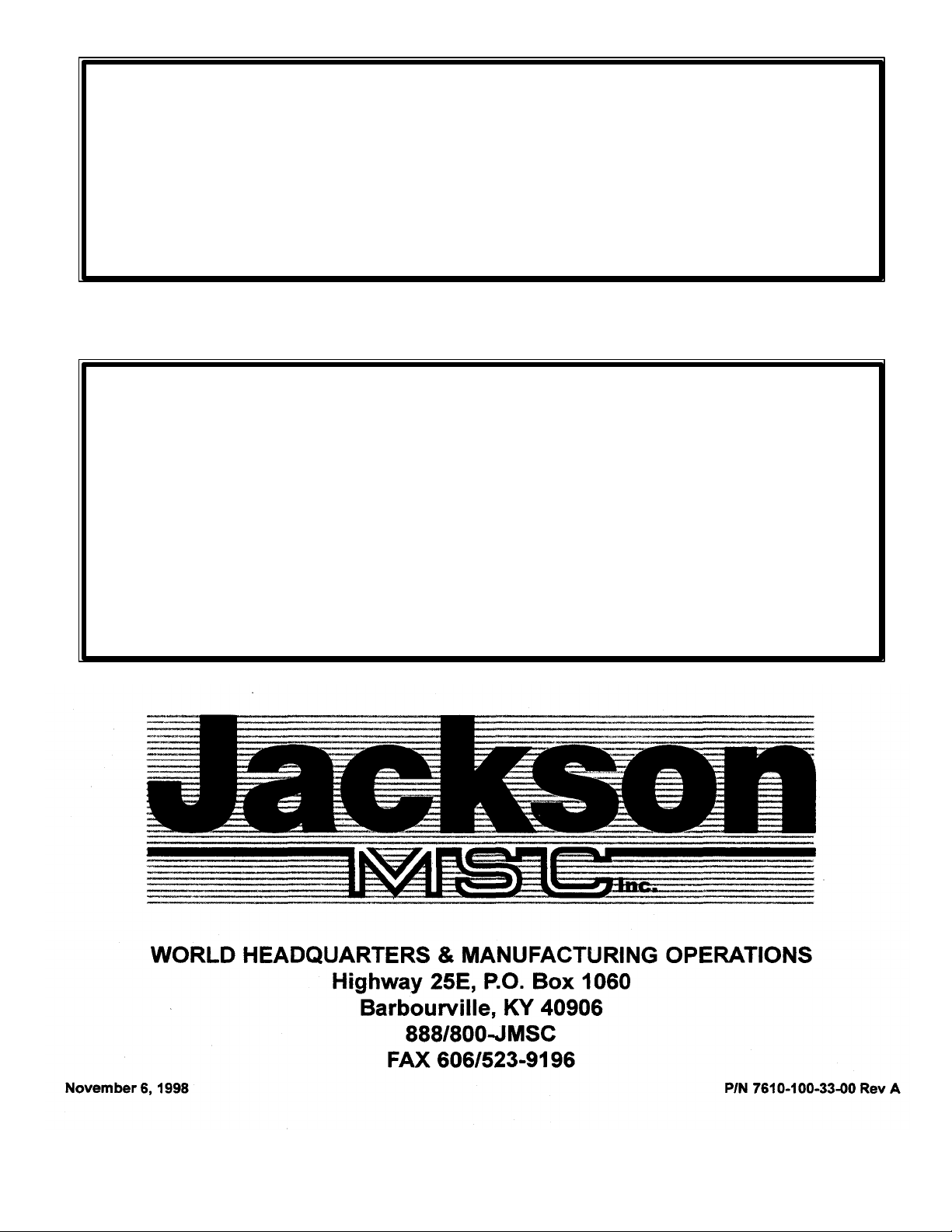
2. Refer to the dimensional data sketch for connections.
3. The drain from the machine is a GRAVITY DRAIN SYSTEM and should, therefore, have the proper drop
from the machine to the kitchen's drain system. The drain connection is located to the left rear of the
machine when facing the machine's door. The drain fitting is 1/2" OD tube size, 7" from floor.
4. IMPORTANT-PLEASE READ-Located on the back upper left corner of this unit is a steam equalizing
vent. This vent in no way should be blocked off or prevented from allowing steam to be vented to the
outside of the unit or from under the cabinet in which the unit is installed. Never pipe the steam
downward toward the floor. (SEE PAGE 4 IF BEING INSTALLED UNDER A COUNTER.)
5. The electrical connections should be made to the terminal board located at the left center front. The
terminals are marked L1, and Neutral. Install proper circuit breaker, wire and conduit size to
conform with local and/or national codes (standards).
Page 5
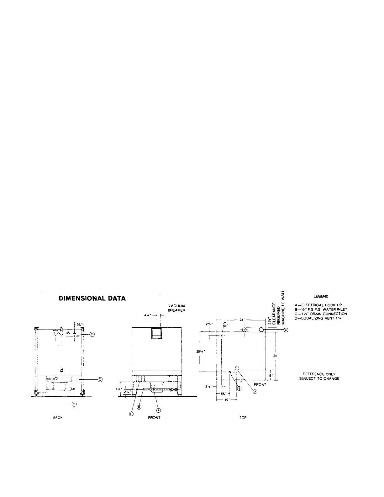
Installation of Model 24 Top and Table gasket:
These instructions are to be used for applying the adhesive backed sponge rubber strip to the top of the
machine prior to setting the table in place.
Included with the Model 24 table is a 6 foot length of 1/4" thick x 1' wide sponge rubber adhesive backed
stripping.
Instructions for applying gasket:
1. Place one end of the stripping along the
complete side of the leg support flange and
cut it off.
2. Repeat the same procedure along the other
side.
3. Place the remaining piece along the front
edge, fit it in between the side pieces and cut
it to length.
4. Remove the backing and set the strips in
place.
Instructions for installation under a porous counter top:
1. If possible, a hole should be cut through the
counter top directly above the equalizing vent.
A piece of 1/4" OD pipe is then inserted
through the hole into the vent opening and
piped to the outside.
2. If cutting a hole in the counter is not possible,
then a piece of stainless steel 36" wide by 36”
long bend in the middle at 90° should be
centered directly over the vent to allow the
steam to condensate on it when it comes out
of the vent.
3. It is very important that this vent be kept open
and cool air allowed to circulate around the
unit.
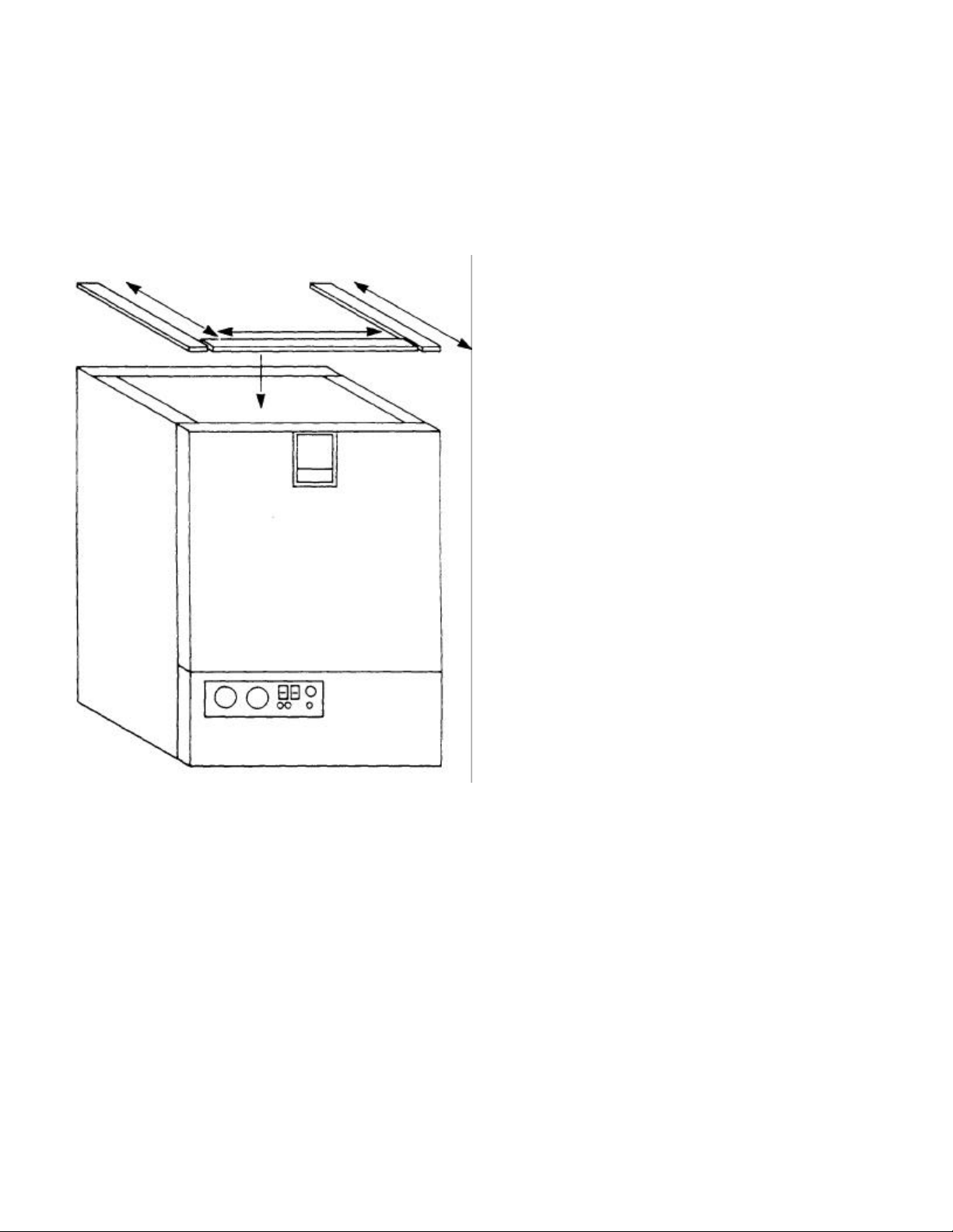
Installation of Model 24 Dishwasher Under Dishtable:
1. On the end of the table, locate bracket #4 opposite the sink end.
2. A square rubber gasket #3 is supplied and should be secured to top frame of
dishwasher with caulk or suitable adhesive.
3. Place dishtable #2 where it is to be installed and support the machine's end.
4. Slide dishwasher #1 underneath dishtable #2 so that the outside of machine is
positioned against the guide bracket #4. Make sure dishtable and dishwasher are in
desired permanent location.
Page 6
5. Using the two holes in bracket #4 as a guide, drill two holes 9/64" diameter in the side panel of
machine. Note: Drill through first thickness of metal only.
6. Using the self-tapping screws supplied, screw them through bracket #4 and into the side panel of
machine until screws are tight.
Removal of Pan Strainer for Cleaning: (Wash and rinse head assemblies must be removed prior to
removing strainer.)
1. Turn heat switch 'off and drain machine by depressing drain switch for approximately
50 seconds.
2. Remove wing nut from rinse feed pipe, remove rinse head assembly by pulling forward.
3. Remove wing nut from upper pump housing, wash head may now be lifted out.
4. Pan strainer now accessible, lift out and clean thoroughly.
5. Clean around pump intake with bristle brush.
6. Replace stainer pan.
7. Re-install wash and rinse head assemblies.
8. Clean strainer pan daily or as needed to insure proper machine operation.
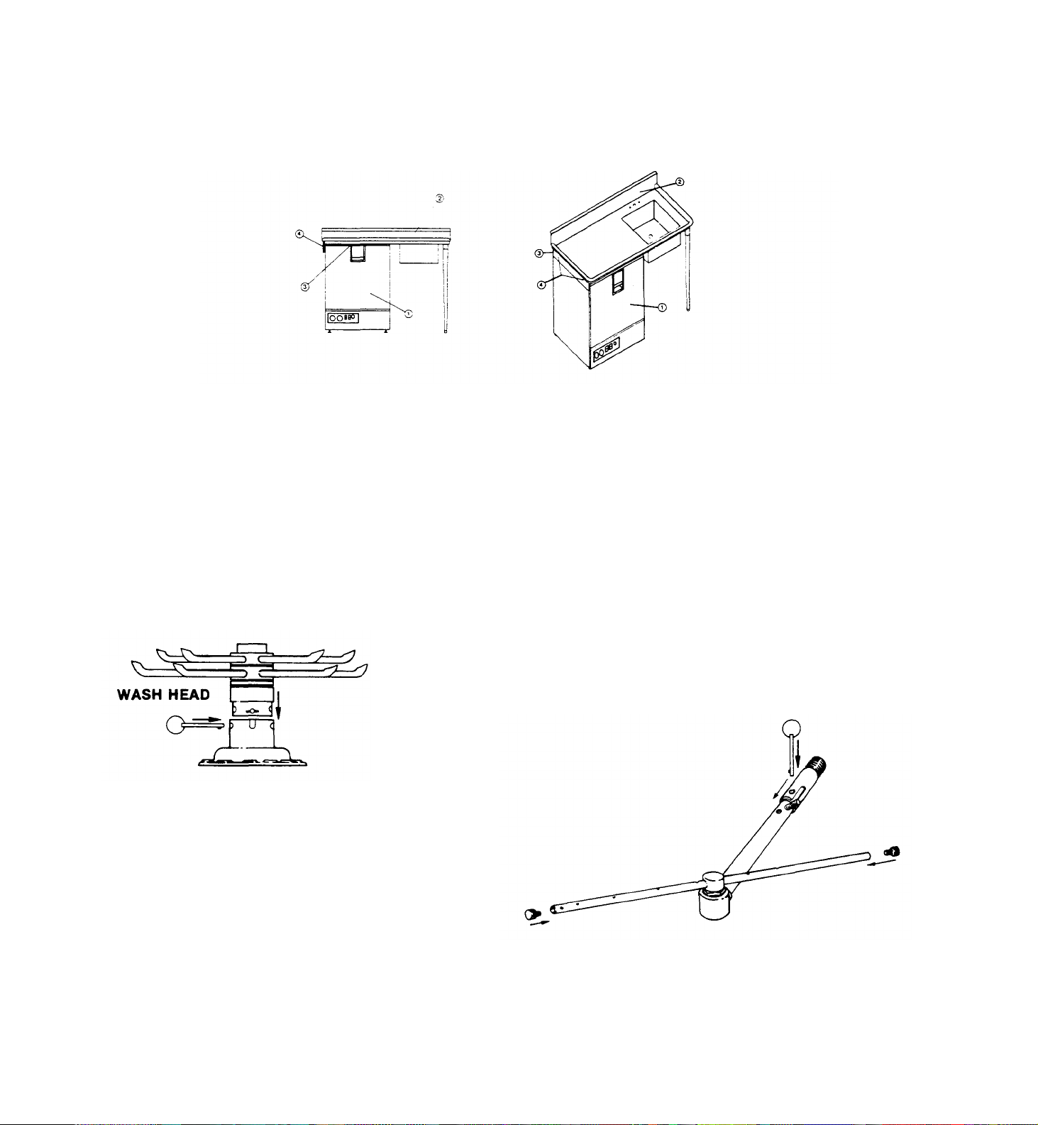
Installation of Wash Head and Rinse Arm Assemblies: (Items disassembled for shipment)
1. Line holes up on wash head assembly to match slots in pump housing.
2. Insert wash head assembly down into upper pump housing as far as
possible.
3. Insert retaining pin to secure wash head to pump housing.
RINSE ARM ASSEMBLY
1. Line up stud to match with slot in nipple.
2. Insert rinse arm assembly into female receptical protrudeing through back of
machine.
3. Insert lanyard pin to secure rinse arm assembly properly.
4. Make certain end plugs are secured properly in rinse tubes.
Page 7

GENERAL INSTRUCTIONS
(OPERATION)
Note: Read the following instructions carefully. Proper operation of your Jackson
Dishwasher will assure clean and sanitized glasses and dishes, at optimum efficiency.
Dish Preparation:
1. Scrape dishes thoroughly.
2. Pre-wash dishes by soaking or with hose.
3. Place dishes and cups in dish rack, cups upside down.
4. Place glasses and silverware in combination glass-silverware rack, glasses upside
down. Scatter silverware loosely on bottom.
Note: Silverware in the upright position washes and rinses better than lying flat. These
silverware compartment racks are available through your dealer or Service Agency.
24B/BF Operating Instructions:
1. Install pan strainer and the wash and rinse arms. Insert an empty rack, close the door
and push till the handle latches.
2. Push the on/fill-off/drain switch to the up "on/fill" position. The machine power light
will come on and so will the rinse heaters. The machine will begin to fill automatically
and stop by itself.
3. After the machine has completed filling, open the door and put in a rack of soiled
dishes and close the door (the machine door must remain open for a minimum of 5
seconds to allow the timer to reset.)
4. After the door has been closed, the cycle light will come on. There will be a 4 second
delay before the wash cycle begins.
5. The machine will wash for 120 seconds and rinse for 15 seconds. After the cycle has
finished, the cycle light will go out.
6. Open the door and remove the sanitized dishes. The machine is ready for another
cycle.
7. To manually wash, push the manual wash switch to the up "on" position. The machine
will wash indefinitely. This function can also be used as a delime. To resume normal
operation, push the manual wash switch to the down "off" position.
8. To drain the machine, close the door and latch. Push the on/fill-off/drain switch to the
"off/drain" position. This must done within 4 seconds after closing the door or else the
machine will begin another normal cycle.
9. After machine has drained, the cycle light will remain on for 1 minute and 30 seconds.
This allows the timer to reset for the next meal period.
10. Open the door, remove and clean the pan strainer and wash arm.
11. Wash heater protection is provided by two means. Primary protection is given by the
water level control which senses the water level with a probe. If this should fail due to
excessive build up on the probe, the secondary thermal protection will cut out the wash
heater before damage occurs.
12. When the secondary heater protection has been used, it will be indicated by the
illuminated red reset light. The following steps are necessary in this situation:
a. Turn off power supply.
b. Open the door and remove the wash and rinse arms and the pan strainer.
c. Locate the two probes. One is in the wash sump on the left hand side and the other
is on the front of the wash tub under the probe cover.
d. Using a deliming compound and a brush, clean both probes.
e. Reinstall the wash and rinse arms and the pan strainer.
f. Push the reset button located above the reset light.
g. Push on/fill-off/drain switch to the "on/fill" position. The machine should begin to
fill. If it does not and the reset light comes on again, call an authorized service
agency.
Detergent Recommendations and Rinse Additives:
We suggest that you contact your local Detergent Specialist for the correct detergent and rinse additives
for your area. To help you until one can be reached, we suggest that you use a non-foaming dishwasher
detergent, approximately three tablespoons in wash tank when machine is filled and one teaspoon each
cycle or load thereafter. This may have to be increased or decreased to obtain satisfactory results.
Page 8

GENERAL INSTRUCTIONS
(PREVENTIVE MAINTENANCE)
(THE FOLLOWING IS TO BE PERFORMED AS NEEDED.)
Note: Read the following instructions carefully. Proper maintenance of your Jackson
Dishwasher will ensure optimum service with a minimum of down ti me.
1. Remove all lime and corrosion deposits.
a. Fill the machine with wash water as would ordinarily be done for washing.
b. Open door and place one cup or less of de-liming compound into the water. The
compound is available from your detergent supplier.
c. Turn on the manual wash switch and allow to wash for five minutes.
d. Open door and examine the interior. All lime should be removed and parts should be
shiny. If not, allow to wash for longer period.
e. After the interior is clean, with door closed, empty the wash water by turning switch to
the "off/drain" position. Refill machine and allow to run for two minutes, then again
drain the wash reservoir.
2. Clean around overflow strainers and drain hole.
a. Clean around overflow and strainer pan.
b. Clean around pump intake (toothbrush makes excellent tool for cleaning).
3. Clean Y-strainer on incoming water line. (Water to machine must be turned off for this
operation)
a. Remove plug and clean strainer.
4. Clean rinse tubes.
a. Remove rinse assembly by disconnecting rinse feed pipe and removing end plugs
on lower rinse.
b. Clean all rinse tubes and feed pipes with special brush supplied.
c. If spray holes in the rinse tubes are clogged, they may be cleaned with a pointed
object.
5. Clean wash head assembly.
a. Remove pin holding wash head assembly to pump.
b. Clean assembly at sink by flushing water through spray jets.
c. If spray jets are still plugged, use sharp object to dislodge and flush again.
d. Reinstall wash and rinse assemblies. (See page with instructions.)
6. Clean any deposits which may have built up on exterior moving parts.
a. Clean around door gasket.
b. Using a soft bristle brush, clean around switches on exterior of control panel. (Use no water.)
c. Use soft bristle brush, dip in wash tank water and scrub inside door around gasket
and hinges. Use clean cloth or paper towel to wipe off loose residue.
Page 9

REMOVAL of RINSE and/or
WASH HEAD ASSEMBLIES
(GENERAL INSTRUCTIONS)
1. Drain unit by placing switch in the off/drain position.
2. Open the door and allow the unit a few minutes to cool off.
3. Remove the pin holding the rinse feed pipe. Pull the feed pipe out of the nipple and lay
it to one side.
4. Remove wash head assembly by pulling out the holding pin and lifting assembly. Place
the wash head on a table for disassembly.
5. Locate Allen head set screw in the wash head cap, insert Alien wrench and loosen
screw by turning counterclockwise.
6. Turn wash head cap counterclockwise until cap is removed and put cap in safe place.
7. Remove 1/4" stainless ball bearings carefully and put it in a receptacle in a safe place.
8. Lift and remove small manifold with short tubes. Put it in a safe place.
9. Remove 1/4" ball bearing in similar method to step #7.
10. Lift and remove large manifold with large length tubes similar to step #8.
11. Clean ball bearings by soaking in de-liming solution.
12. Ball bearing race ways may be cleaned by either brushing with de-liming solution
(toothbrush makes excellent tool) or gently clean by rubbing with fine sandpaper or
emery cloth.
13. Rinse ball bearings and manifolds thoroughly.
14. To reassemble, first fill lower race to capacity with V1/4" ball bearings, then remove one.
This will give proper movement needed during rotation of assembly.
15. Replace lower manifold and fill race fully with 1/4" ball bearings. Repeat, removing one
only.
16. Replace upper manifolds and repeat necessary parts of step #14.
17. Replace wash cap by screwing on center shaft clockwise, finger tight.
18. Back off wash cap about V* turn and tighten Allen set screw.
19. Rotate manifolds in opposite directions; see if they rotate freely. A rule of thumb is to
select the longest tube in the bottom manifold and make sure it moves up and down at
least 1/2" and no more than 1/4" .
20. Replace wash head assembly and rinse arm.
21. Close the front door and refill dishwasher.
22. Run through several cycles and recheck wash arms for easy movement. Adjust if
necessary.
Page 10
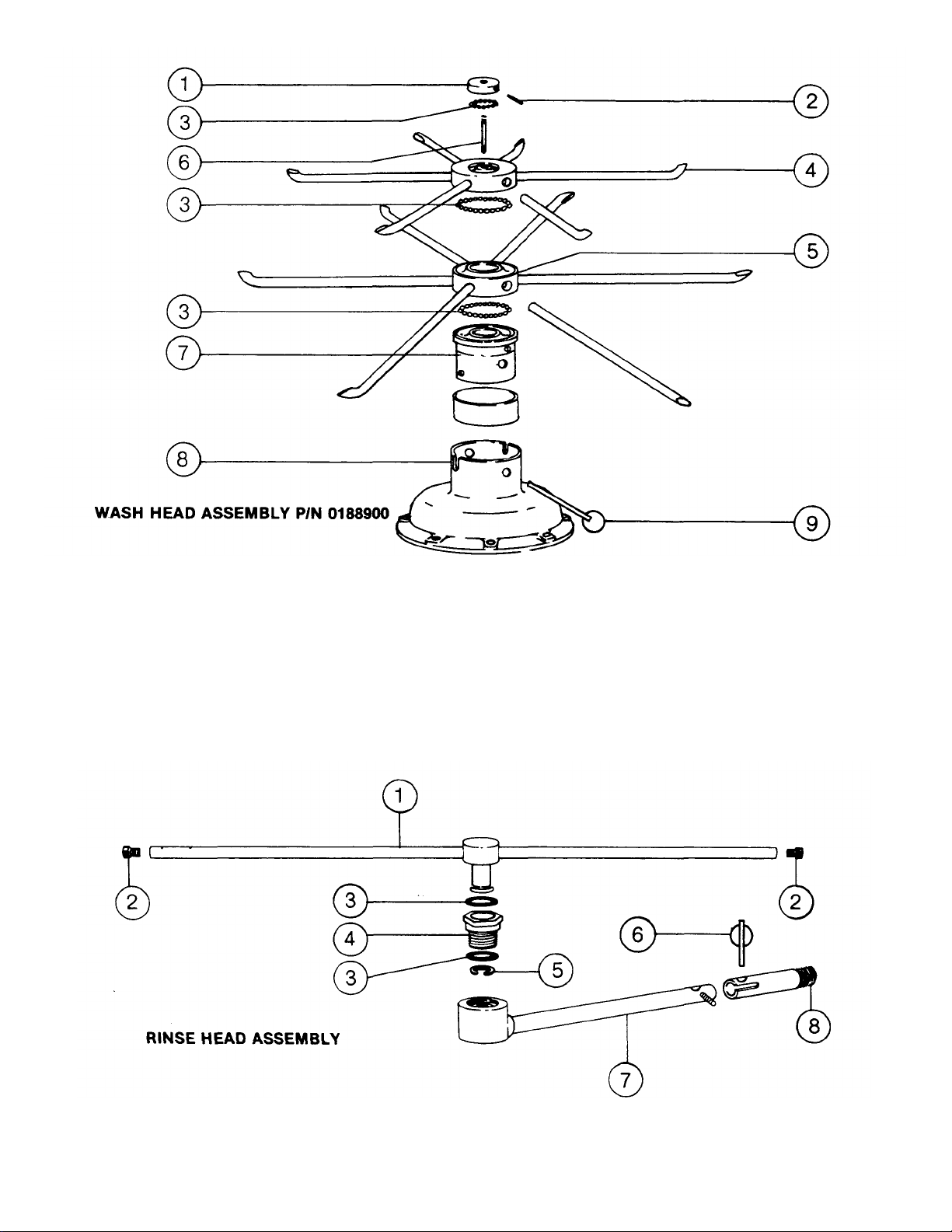
4.
8.
ITEM P/N
1. 0186500 WASH HEAD CAP WITH RACE 6. 0187500 WASH HEAD CENTER SHAFT
2. 0187000 WASH HEAD CAP SET SCREW 7. 0193601 WASH HEAD FIXED RACE
3. 0194000 WASH HEAD BEARING 1/4" S/S 8. 0109600 UPPER PUMP HOUSING
4. 0189000 WASH HEAD SMALL MANIFOLD 9. 0189805 WASH HEAD ASSEMBLY
w/TUBES RETAINING PIN w/RING
5. 0189500 WASH HEAD LARGE MANIFOLD
w/TUBES
DESCRIPTION ITEM P/N DESCRIPTION
ITEM P/N DESCRIPTION ITEM P/N
1. 0125200 RINSE HEAD ARM 5. 0126500 RINSE HEAD SNAP RINGS S/S
2. 0126800 RINSE HEAD END PLUGS 6. 0137301 RINSE FEED PIPE LANYARD PIN
3.
0126000
0125500
RINSE
RINSE
HEAD
HEAD
NYLATRON WASHER
HEX BRUSHING S/S
7.
0137200
0137202
RINSE
RINSE
DESCRIPTION
FEED PIPE (LOWER) FEED
PIPE NIPPLE
Page 11

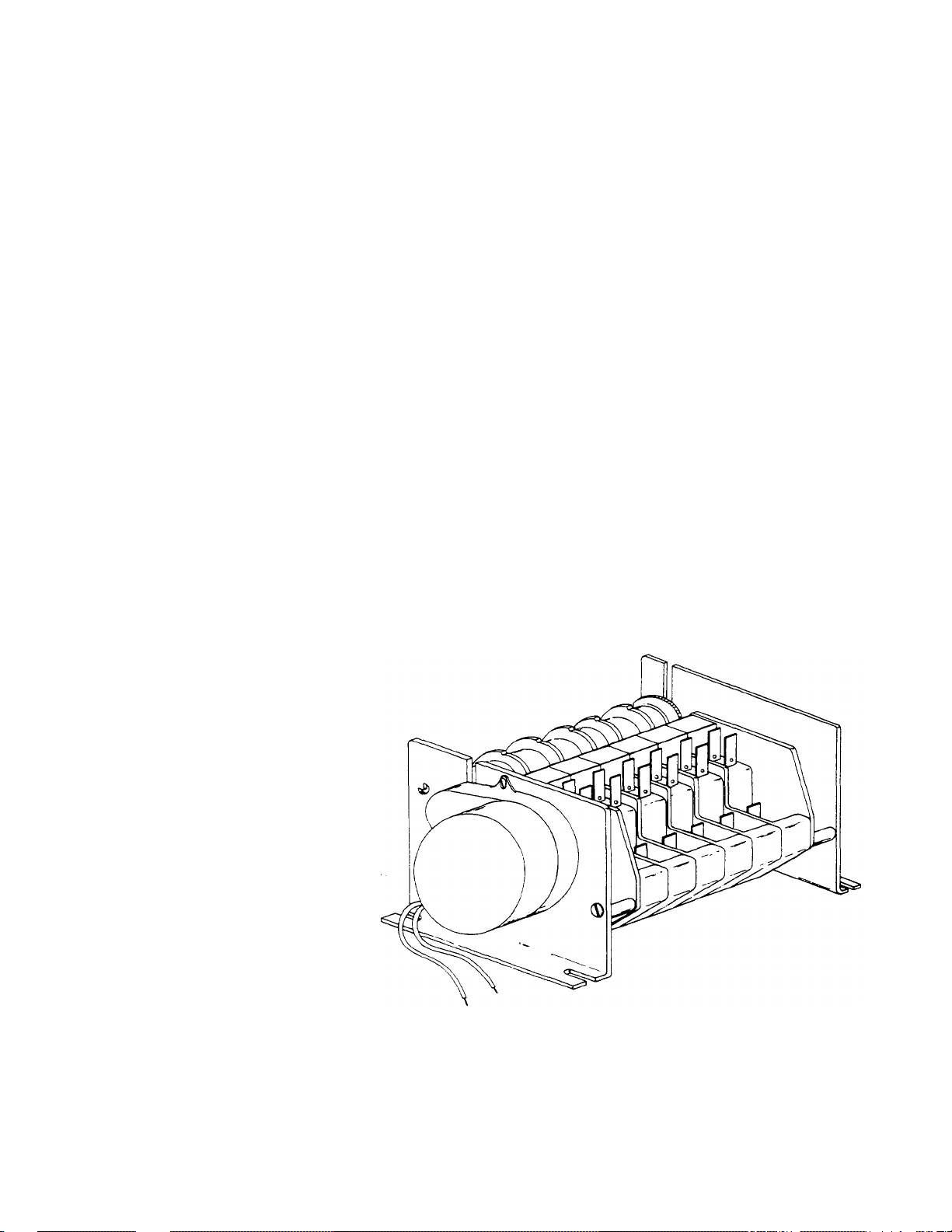
TIMER for MODEL 24
DISHWASHERS
General Description:
The timer is a self-contained (frame mounted) timer of the repeating cycle type. It is mounted to the
control panel of Jackson Automatic Dishwashing Machines, to control the automatic functions of these
machines. It consists of a clock motor which operates on 60 cycle, AC, 110VAC. In addition to the clock
motor, the timer also contains a driven cam arrangement which operates six micro switches.
Principle of Operation:
The timer controls various operations of the automatic washers as per wiring diagram for each machine;
however, the timing cycle and the micro switches are the same for each model. The time for
One Complete Revolution of the cam shaft is approximately 150 seconds, allowing one wash and one
rinse operation for each complete revolution of the cam shaft.
Service Instructions:
Caution: Always remove the power to the machine before working on the control panel or while
servicing the components on the switch panel. All electrical checks should be made by
qualified personnel.
Timer operation can be observed after removing the machine's kickplate by loosening the two screws
holding it.
If it is determined that the timer is defective, determine which micro switch or if motor is defective. The
motor and the micro switches are easily changed.
A frozen contact on a micro switch will be indicated if one function of the timer is being executed all the
time or if there is an absence of a click when the switch arm is actuated.
To Replace Micro Switch:
1. Push upward on micro switch terminals (away from cams) until actuator button shows.
2. Pull micro switch straight out.
3. Replace, wire for wire, with new micro switch.
4. Replacing micro switch into timer is simply a reverse of steps 1 and 2.
The timer's cam drive system is equipped with a clutch to enable one to view the operations of the cams
and micro switches. Remove power to machine before touching timer. Rotate cams by turning with
fingers; cams will turn in one direction only. Do not force them. As cams actuate switches, listen for the
'click' of the switch or test the switches with an ohmmeter.
Page 12
DEFECTIVE TIMER MOTOR
A defective motor is indicated by the fact that the cams do not rotate or the machine does not perform the
automatic operations, or performs a specific part of the cycle continuously, but works okay on manual.
Remember, the timer motor is controlled by the door switch and the hold micro switch; check this complete
circuit before changing motor.
To Replace Motor
1. Remove motor leads from shorting bar and neutral.
2. Remove the two screws which hold the motor.
3. Replace with a new motor.
TYPICAL TIMER SWITCH P/N 0177500
TIMER
P/N 0174200 (110V, 60 cycle)
Page 13

FUNCTION of SWITCHES, CIRCUIT
Cycle Light:
BREAKER and INDICATING LIGHTS
On/Fill This switch serves as the main control for the unit. When pressed into the
Off/Drain 'on' position, it activates the heater controls, the automatic fill and readies
Switch: the unit for the wash cycle. When turned off, this switch signals the
P/N 0159600 automatic drain and turns off all power once draining is completed.
Power Light: This light comes on when the unit is turned on and goes off when the unit is
P/N 0083518 turned off.
Door Switch: Located on top of the unit, behind the latch bracket, this switch serves three
P/N 0164000 functions. When the door is opened, it will reset the timer to the cycle
starting position. When door is closed, it will start the automatic cycle. If door should be
opened during a cycle, it would act as a safety switch by turning the unit off.
P/N 0083501
Manual Wash
Switch:
P/N 0159700
Heater Reset This is the reset button on a thermostatic overload. Its purpose is to provide
Button: a secondary protection for the wash tank heater element. If the heater
P/N 0169601 element should come on while the wash tank is empty, this button would
pop out, turning off the element and signaling a problem with the automatic
fill.
Reset Light: This light comes on only when the heater reset trips off. Its purpose is to
P/N 0083518 signal that there is a problem.
This light comes on only when the automatic cycle is in progress and goes off when the
cycle is complete.
This switch is used to bypass the timer and operate the wash pump manually. The wash
pump will run as long as this switch is 'on'. Its prime purpose is to extend the wash period
for heavily soiled dishes, but it may be used for deliming.
Page 14

THERMOSTAT ADJUSTMENT
THERMOSTAT
The thermostat can be adjusted by turning screw #1 (see picture) on the thermostat control box cover.
(Remember the present setting, in case the problems are elsewhere in the control circuit.) A CW rotation is
used to obtain a lower temperature setting and a CCW rotation is used to obtain a higher temperature
setting. A 1/ 8 turn of screw #1 changes the temperature approximately 15 °F. If screw #1 is turned all the way
to its stop in either direction, adjust screw #2 as follows.
Note: Do not touch the screw sealed with red paint. When adjusting screw #2, power should be
disconnected during adjustment.
Set screw #1 so that it can be turned equal distances in either direction, then:
— if screw #1 stopped while turning in CW direction, turn screw #2 in CW direction, slowly
and only 1/8 of a turn or less per complete cycle of the unit.
— if screw #1 stopped while turning in CCW direction, turn screw #2 in CCW direction,
slowly and only 11/8 of a turn or less per complete cycle of the unit.
Three-fourths of a turn will bring the thermostat to approximately the same setting obtained where screw #1
stopped. Check the present temperature setting before attempting any further adjustments. Use screw #1 for
any further adjustment s.
Making large moves in adjusting may cause misalignment, thus increasing chances that further adjustment
cannot be made and thermostat will have to be replaced.
PAST: P/N1700
PRESENT:
P/N 0170018-Rinse
and 0170023-Wash
Page 15

RINSE TANK HEATER SYSTEM
Function:
The Rinse Tank Heater System is electrically connected in the circuit with the control system functioning
on 110/130V and the power system functioning on 208/230V for both systems. The heat circuit is
controlled by the 'on/fill' switch (mounted on front panel) and a thermostat (mounted near thermometer)
which activates the coil on the heat relay. When higher temperature is required, power is applied to the
heaters when the contacts of the heat relay are closed. Should the rinse tank thermometer read either
too high or too low, follow checkout below.
Checkout of Heater System for Rinse Tank: (Refer to drawing, Figure #2)
Note: The following checkout should be done by a qualified service person or electrician.
1. Turn off power to machine by tripping circuit breaker to 'off position.
2. Remove front kick plate below door.
3. Make sure rinse temperature is below 180°.
4. Reapply power and observe heat relay (2pole) letter G, figure 2, (next to timer) as 'on/fill'
switch is turned on and off several times.
AA If heat relay contacts do not close, with 'on/fill' switch on:
1. Check power supply at Position 1 on terminal board X. Voltage should be 110VAC.
2. Check Position 3; there should be 'zero' volts there. If not, readjust thermostat per thermostat
instructions.
3. If voltage is being applied to Position 1, then the relay should be replaced; coil on relay probably
defective.
BB To determine if elements are working:
1. There's an insulated movable bar on the heat relay across the top of the two
contacts. With an insulated probe, depress the bar and observe rinse thermometer;
the temperature should rise noticeably in a minute or two. If it moves very slowly, it
would indicate that one element is defective. If it moves consistently higher at a
good rate, the elements are okay.
Note: A check with an amp probe, if available, can be made.
The element should draw 28 amps. Replace element if found defective.
CC If the heat relay closes:
1. Check power supply at Position 4 on terminal board X, right hand view. It should be 220V
approx. If not, check circuit breaker at customer's panel; replace if defective.
2. Check power at Position 5; voltage should be 220V. If not, check connections and wires for
breaks; replace as necessary.
3. With 'on/fill' switch on and relay closed, check power at Position 6; voltage should be 220V. If
not, replace heat relay.
4. If No. 3 above checks out okay, check at Position 7; voltage should be 220V. If not, check wiring
from heat relay to elements for loose connections or broken wires;
repair as necessary.
Page 16

A - ON/FILL SWITCH F - RESET LIGHT
B - WATER LEVEL CONTROL G - RELAY
C - THERMOSTAT H - RINSE HEATER
D - (WASH) RING HEATER X - TERMINAL BOARD
E - THERMOSTATIC OVERLOAD
Page 17

WASH TANK HEATER SYSTEM
Function:
The Wash Tank Heater Control system is electrically connected in the circuit to operate on 220V
regardless whether system is 60 or 50 cycle. The heat circuit is controlled by a water level control
(mounted middle of control panel), thermostat (mounted near thermometers), and thermostatic overload
(located beside manual wash switch). When higher temperature is required, power is applied to the
heater element through above controls. Should the wash tank thermometer read either too high or too
low, follow checkout below.
Checkout of Heater System for Wash Tank: (Refer to drawing, Figure 1.)
Note: The following checkout should be done by qualified service personnel or electrician.
1. Ready machine for normal dishwashing operat ion with wash tank water at proper level.
2. Remove front kickplate below door.
Note: Power's still applied to circuit, so be careful.
3. Check power to machine at Position 1; terminal board X should read 110V. If not, check customer's
circuit break er. If defective, replace.
4. Wash temperature should be 130° or less to proceed.
5. Observe water level control, letter 'B' (with front door closed and latched). Turn 'on/fill' switch on and
off several times. Relay and contact points (inside clear plastic case on water level control) should
move back and forth.
AA If water level control relay doesn't close, refer to page on Water Level Control's
function and checkout.
BB If water level control relay does close, proceed with 'on/fill' on.
1. Check voltage at Position 1 on terminal board X. Voltage is 110.
2. Check Position 3, Figure 1; there should be no voltage. If there is voltage, then adjust
thermostat (refer to page on Thermostat Adjusting).
3. Check reset light. If light is on, push reset button.
4. Check Position 5, Figure 1, voltage should be 220. If not, check Position 8, there should be
220V.
5. Temperature should rise slowly, a check with an amp probe would indicate if the element is
drawing the correct amperage. Replace element if defective.
Page 18

WATER LEVEL CONTROL
AS USED ON 24
P/N 0204500 (110V, 60 cycle)
Function:
The water level control device is utilized on this machine to automatically control the filling of the wash
tank and the activation of the wash tank heater.
Note: All electrical checks should be made by qualified service personnel.
The control is designed to sense when the proper water level is reached. At this time, the relay in the
clear plastic case will activate, opening the auto fill circuit and closing the circuit to the thermostat which
completes the wash tank heat circuit as it closes. If one of the following problems exist, this unit should
be checked out as shown below.
Symptoms of Level Control Failure:
1. Automatic fill will not shut off when water reaches the proper level.
2. Machine will not automatically fill when 'on/fill' switch is activated.
3. Wash heater reset trips off.
Proceed with Checkouts:
1. Remove power source to machine by moving circuit breaker to 'off position.
2. Remove screws holding lower kick plate on front of machine and locate water level control (sketch
below).
3. Remove, mark and insulate, for easy replacement, wires going to letters C & H.
4. Re-apply power, turn on 'on/fill' switch. With an insulated wire, connect Jumper wire between
terminals C & H (24 volt system).
5. If relay operates, the water level control action can be deemed operational; then other causes
should be explored.
6. If relay doesn't operate, replace control.
7. Remove power source once again and replace wires that were removed In step three to original
terminals (see trouble shooting section for other possible causes).
Page 19

SERVICE INSTRUCTIONS
(INCOMING WATER SOLENOID VALVE)
SOLENOID VALVE
P/N 1421 (110V, used on 60 cycle machine)
To take the valve apart:
Disassembly — These valves may be taken apart by
unscrewing the bonnet and the enclosing tube assembly from
the valve body assembly. See Fig. 3. After unscrewing,
carefully lift off the bonnet and enclosing tube assembly.
Don't drop the plunger. The "0" ring seal and diaphragm
cartridge can now be lifted out.
Be careful not to damage the machined faces while the valve
is apart.
To Reassemble — Place the diaphragm cartridge in the
body with the pilot port extention UP. Hold the plunger with
the synthetic seat against the pilot port. Make sure the "0"
ring is in place, then lower the bonnet and enclosing tube
assembly over the plunger. Screw bonnet assembly snugly
down on the body assembly.
Possible Problems
Pilot Port extension #1 clogged Hole
#2 clogged
Remedy
Pass heated straight pin through hole #2 or
clean hole #1
Page 20

SEAL and CERAMIC for
1.
MOTOR
PUMP SYSTEM
(GENERAL INFORMATION)
The wash and drain pump are part of the total motor pump system. One seal and ceramic are utilized to
prevent the pump from leaking.
Replacement of Seal and/or Ceramic:
1. Drain machine either by depressing drain switch or by bailing out.
2. Turn incoming power to machine off.
3. Open door — remove dolly, racks, rinse head assembly and wash head assembly.
4. Remove kickplate (located under front door).
5. Unplug motor at connector
6. Loosen eight screws holding pump in sump tank.
7. Disconnect drain hose from motor (must be done from underneath machine).
8. Pull motor and pump gently upward and move from side to side as required to remove unit. (Old
machine motor removed downward.)
9. Set pump and motor on bench and proceed.
10. Loosen eight screws holding upper pump housing, and remove housing.
11. Remove diff user plate.
12. Loosen impeller screw and remove impeller.
13. Remove suction adapter plate.
14. Remove drain inlet plate.
15. Remove propeller.
16. Remove mounting plate from motor (loosen 4 phillips head screws on bottom of plate).
17. Knock out old seal carefully and clean hole, re-insert new seal.
Note: Be sure not to ruffle edges of seal when inserting. Seal should contact all
re sting surfaces at one time.
18. Ceramic is imbedded in propeller and normally does not wear or need replacement, but check for
cracks.
19. Re-install motor and pump by reversing above process.
2. MOUNTING PLATE
3. STATIONARY SEAL
4. SHIM WASHERS
ON MOTOR SHAFT
5. CERAMIC
6. DRAIN PROPELLER
Page 21

TROUBLE SHOOTING GUIDE
Wash motor doesn't operate on
PROBLEM
Water overflow out bottom of
front door when wash pump is
operating.
CAUSE
Machine not level.
Overflow drain clogged.
Water level in machine's
wash reservoir too high.
Detergent foaming.
Equalizing vent blocked.
Wires broken or loose.
SOLUTION
Level machine.
Slight tilt to rear
Remove obstruction, checking
inside of machine first.
Solenoid valve not closing at end of
fill or rinse cycle causing excessive
water problem.
Reduce quantity of detergent. Allow
free steam flow.
Check all wires in the motor and
reconnect as necessary.
manual wash.
Defective manual wash
switch.
Bad bearing, noticeable by
noisy bearings or locked
drive shaft.
Replace.
Replace.
Replace.
Defective motor starting
relay. (Typical - motor hums.)
Note: The motor starting relay is utilized to insert a starting field In the wash pump motor, once the
motor has gained speed, the running winding will then take over and the starting winding will
be removed when the relay kicks out.
Motor runs on manual wash but
doesn't operate on automatic
(rinse operates okay on both
manual and automatic cycles.)
No water comes through the
rinse arms when the 'on/fill'
switch is depressed.
Defective micro switch on
timer.
Defective circuit in manual
wash switch.
Hand water valve to machine
not turned on.
Replace switch.
Replace switch.
Turn on water valve.
Defective coil on
solenoid valve.
Probes are dirty or coated.
Little or no water coming
through rinse assemblies.
Defective water level control.
Limed up rinse heads or piping.
Water pressure low.
Replace coil.
Clean probes.
Replace.
Begin by cleaning rinse heads
using instructions for de-liming If
this isn't satisfactory, then clean
the rinse feed pipes.
Increase pipe size to machine
Page 22

TROUBLE SHOOTING GUIDE
PROBLEM
CAUSE
Rinse water runs continuously with
Defective plunger in
Replace plunger.
Defective diaphragm in
Rinse water runs con
tinuously
Defective water level control.
Replace.
Rinse temperature not at required
Rinse doesn't operate on
automatic during timed cycle (but
does operate on auto/fill
operation).
Micro switch defective.
SOLUTION
Replace.
circuit breaker controlling machine
turned off.
Note: In disassembling solenoid valve, use instructions shown on separate page.
with power applied to machine,
but when circuit breaker to
machine is turned off, water
stops.
Note: Excessive water line pressure can cause water to continually run even though the power to the
machine is turned off. Check specifications for required pressure.
solenoid valve.
solenoid valve.
Defective timer that has stopped
in a position keeping the rinse on.
Probes are dirty or coated.
Check both holes in diaphragm
cartridge to insure that they are open.
The one on the outside perimeter
should be the size of an ordinary
straight pin. If it's not, heat a straight
pin and put it through this hole to
enlarge. If this fails to correct
situation, replace diaphragm.
Replace timer motor or
timer as nec essary
Clean probes.
Wash temperature not at
required reading on
thermometer.
Note: Any switches, water level controls, heater elements, relays or contactor that have to be
checked out, can be done using the heater checkout system page.
Defective thermometer.
temperature, causing wash
temperature to be lowered during
rinse cycle.
Using a thermometer (fast reading
type that's known to be correct),
insert in wash rerservoir and check
reading against wash thermometer on
machine. If machine thermomete isn't
correct within three or four degrees,
replace.
Check out rinse heat using heater
checkout system page in manual.
Page 23

TROUBLE SHOOTING GUIDE
PROBLEM
CAUSE
SOLUTION
Rinse water not at required
temperature range.
After filling machine with water,
leakage began at lower front
panel without machine
operating or at end of rinse
cycle.
Machine doesn't drain when
'off/drain' switch is depressed.
Thermostat defective.
Water level protection
control defective.
Heater element defective.
Wires loose or burned off.
Thermometer's defective.
Thermostat defective.
Defective heater relay on
contactor.
Overflow drain clogged.
Drain solenoid clogged.
Defective switch.
Adjust using instructions on
thermostat page and heater
system's checkout page.
Replace if necessary.
Replace. (Auto/fill would run
continuously.)
Replace.
Retighten or Replace.
Replace.
Adjust using instructions on
thermostat page and heater
system's checkout page.
Replace if necessary.
If defective, replace. See note
on heater system above.
Clean away obstruction.
Remove obstruction.
Replace.
Note: The drain pump of this machine is part of wash motor, so if wash motor operates properly drain
system should work.
Defective motor or motor
start relay.
Defective drain solenoid.
Defective micro switch on
timer.
Defective relay.
Replace,
Replace. Replace micro
switch.
Replace.
Page 24

or
0170023
FRONT VIEW
ITEM P/N DESCRIPTION
1. 0052700 DOOR HANDLE ASSEMBLY
2. SWITCHES
3. 0052600 FRONT DOOR
4. 0125100 RINSE ASSEMBLY, UPPER
4A. 0125200 RINSE ASSEMBLY, LOWER
5. 0188900 WASH ASSEMBLY
6. 0005700 BOOSTER TANK
7. 0060000 HEATER ELEMENTS
8. 0142100 SOLENOID, (110V, used on 60 cycle machines)
9. 0185000 VALVE FOR HEALTH INSPECTOR GAUGE
10. 0153600 "Y" STRAINER
11. ELECTRIC PANEL
12. INCOMING WATER CONNECTION
13. 0169100 THERMOMETERS
14. 0170018 THERMOSTATS
Page 25

ITEM P/N DESCRIPTION
1. 0184101 VACUUM BREAKER ASSEMBLY
2. 0108100 PUMP & MOTOR ASSSEMBLY, (110V, 60 cycle)
3. DRAIN — GRAVITY FEED
4. 0005700 BOOSTER TANK
5. 0185900 EQUALIZING VENT
6. INCOMING WATER CONNECTION
Page 26

ITEM P/N DESCRIPTION
1. 0184101 VACUUM BREAKER ASSEMBLY
2. 0052700 DOOR HANDLE ASSEMBLY
3. 0052600 FRONT DOOR, OUTER
4. 0054902 KICK PANEL
5. INCOMING WATER CONNECTION
6. 0083400 ADJUSTING FEET
7. 0108100 PUMP & MOTOR ASSEMBLY, (110V, 60 cycle)
8. DRAIN — GRAVITY FEED
9. 0142400 DRAIN SOLENOID VALVE, (110V, used on 60 cycle machine)
10. 0004001 SIDE FRAME & BRACE, LEFT HAND
Page 27

ITEM P/N DESCRIPTION
1. 0184101 VACUUM BREAKER ASSEMBLY
2. 0125100 RINSE ASSEMBLY, UPPER
2A. 0125200 RINSE ASSEMBLY, LOWER
3. 0004000 SIDE FRAME & BRACE, RIGHT HAND
4. 0188900 WASH ASSEMBLY
5. 0005700 BOOSTER TANK
6. 0083400 ADJUSTING FEET
7. 0054902 KICK PANEL
8. 0052600 FRONT DOOR
9. 0052700 DOOR HANDLE ASSEMBLY
10. 0054700 OPTIONAL TOP
Page 28

ITEM P/N DESCRIPTION
1. 0153600 "Y" STRAINER
2. REMOVABLE FILTER
3. 0185000 VALVE FOR HEALTH INSPECTOR
4. 0142100 SOLENOID VALVE 1/2",
(110V, used on 60 cycle machine)
5. PIPE UNION
Page 29

ITEM P/N DESCRIPTION
1. 0056900 WASH TANK RING
ELEMENT
2. 0125200 RINSE ASSEMBLY,
3. LOWER
3. 0188900 WASH ASSEMBLY
4. WASH RESERVOIR
5. HOLES FOR WASH
TANK ELEMENT
RINSE TANK
ITEM P/N DESCRIPTION
1. 0005700 BOOSTER TANK
2. 0060001 BUSBAR
3. 0060000 BOOSTER HEATER
ELEMENT
4. THERMOSTAT COUPLING
5. 0060002 HEATER ELEMENT
GASKET
6. WATER INLET
7. THERMOMETER
COUPLING
8. WATER OUTLET
WASH OR RINSE THERMOSTAT
P/N 0170018-Rinse
0170023-Wash
Page 30

1.
BOOSTER TANK
HEATER ELEMENT P/N 0060000
THERMOSTATIC OVERLOAD
2. ELEMENT GASKET P/N 0060002
P/N 0169601
Page 31

PUMP AND MOTOR ASSEMBLY
P/N 0108100
PUMP AND MOTOR ASSEMBLY
ITEM KIT# DESCRIPTION
1. 0108100 MOTOR (SOLD AS ASSY. ONLY)
2. 0108501 MOUNTING PLATE
3. 0108501 STATIONARY SEAL ASSEMBLY
4. 0109001 SHIM WASHERS
5. 0108501 ROTATING CERAMIC
6. 0108501 PROPELLER FOR DRAIN PUMP
7. 0109501 "0" RING SEAL
8. 0109501 DRAIN INLET PLATE
9. 0109501 SUCTION ADAPTER PLATE
10. 0108501 IMPELLER FOR WASH PUMP (ALSO 0109000-IMPELLER ONLY;
11. 0109501 TRUSS HEAD SCREW • W/"0" RING
12. 0109501 DIFFUSER
13. 0109501 UPPER PUMP HOUSING
14. 0109700 FILL HEAD MACHINE SCREW (SHORT)
15. 0109800 FILL HEAD MACHINE SCREW (LONG)
16. 0108602 SEALING WASHERS
17. 0108400 PUMP GASKET
18. 0108601 MOUNTING CLIPS
0108600 NOT SHOWN—PUMP TINNERMAN KIT (INCLUDES ST. RELAY
AND KEY #'S 17,18,14,15,16) COMES W/0108100 ASSY
Page 32

DRAIN VALVE
CUTAWAY VIEW
P/N 0142400 (110 V, used on 60 cycle machine)
ITEM P/N DESCRIPTION
1. 0169100 THERMOMETERS, WASH AND RINSE
2. 0170018 THERMOSTAT
or
0170028
3. 0083518 POWER LIGHT
4. 0083501 CYCLE LIGHT
5. 0159600 SWITCHES
6. 0083518 RESET LIGHT
7. 0121300 MOTOR RELAY
8. 0169601 THERMOSTATIC OVERLOAD
9. 0165600 TERMINAL BOARD, INCOMING ELECTRICAL CONNECTION
10. 0124600 MOTOR REVERSING RELAY
11. 0120701 MOTOR STARTING RELAY
12. 0120500 HEATER RELAY
13. 0174200 TIMER
PANEL
Page 33

Page 34

Page 35

Page 36

COMPLETE PARTS LIST for MODEL 24
0005700 Booster Tank(stripped) 1
0051700 Door Latch and Switch Bracket 1
0052300 Door Gasket 1
0052400 Door Gasket, Clamp Assembly 1
0052600 Door, Front, Outer only, stripped 1
0052700 Door Handle 1
0053400 Drain Hose-Pump to Solenoid Valve, short 1
0053500 Drain Hose Clamps 4
0053600 Drain Hose-Solenoid Valve to Drain, long 1
0054400 Door Spring 2
0054500 Enclosure Panel, righthand side 1
0054600 Enclosure Panel, lefthand side 1
0054700 Enclosure Panel, top 1
0054902 Enclosure Panel, Lower Kickplate 1
0056900 Heater Element, ring-style, 1000W, 220V 1
0060000 Heater Element, Flange Type, 208/230V, 6200W 1
0060001 Heater Element, Flange Type, Bus Bars 2
0060002 Heater Element, Flange Type, Gasket 1
0083501 Light, Indicator, Amber 1
0083518 Light, Indicator, Red 2
0084300 Probe, Lundy, small 1
0108100 Pump Assembly, complete with motor, 115V, 60 cycle 1
0108400 Pump Gasket 1
0108500 Pump Propeller Mounting Plate and Seal Assembly, kit 1
0108700 Pump Diffuser(only) 1
0109000 Pump Impeller, kit 1
0109500 Pump, Upper Housing, kit 1
0109600 Pump, Upper Housing, (only) 1
0109700 Pump Fill Head Machine Screws, short 4
0109800 Pump Fill Head Machine Screws, long 4
0117500 Rack, square, 19 3/4 " x 19% "(cup, bowl, glass) 1
0117800 Rack, square, 19 3/4 x 19 3/4" (dish-molded) 2
0120500 Relay, 110V, 2-pole, HW Heat Circuit 1
0120701 Relay, 110V, MotorStarting 1
0121300 Relay, Motor 2
0124600 Relay, Motor Reversing 1
0125100 Rinse Head Assembly, upper 1
0125200 Rinse Head Assembly, lower 1
0125300 Rinse Head End Plug,knurled 2
0125500 Rinse Head, Hex Bushing 2
0125700 Rinse Head, upper, Dual Systems 2
0126000 Rinse Head, Nylatron Washer 2
0126500 Rinse Head, Snap Ring, s/s 2
0131000 Rinse Head Brush, Tube Cleaning 1
0137301 Rinse Feed Pipe Lanyard Pin 1
0142100 Solenoid Valve 1/2",JE, 110V 1
0142400 Drain Valve, Dole 1/2 ", 110V, (Valve only) 1
0143600 Solenoid Valve Coil,110V, JE 1
0145000 Solenoid Valve Diaphragm Cartridge & "0" Ring, JE 1
0147500 Solenoid Valve "0" Ring,JE 1
0148600 Solenoid Valve, Plunger Assembly, JE 1
0149500 Solenoid Valve, Strainer Screen,JE 1
0153100 Strainer, Pan-Type 1
0159600 Switch, On/Fill-Off/Drain 1
0164000 Switch, Door, SPDT 1
0159700 Switch, Manual Wash 1
Page 37

COMPLETE PARTS LIST for MODEL 24
0165600 Terminal Board,3-pole 1
0169100 Thermometer, 36" Cap., Rinse 1
0169601 Thermostatic Overload, Heater 1
0170018 Thermostat, Rinse, 180° fixed 1
0170023 Thermostat, Wash, 150°, fixed 1
0174200 Timer, 115V w/wires, 6-cam 1
0177500 Timer Micro Switches, Plastic Module-Type 3
0184101 Vacuum Breaker, 1/2 " Conbraco 1
0184200 Vacuum Breaker Repair Kit, 1/2" Conbraco 1
0186500 Wash Head Cap w/Race 1
0187000 Wash Head Cap Set Screw 1
0187500 Wash Head Center Shaft 1
0188600 Wash Head Holding Pin 1
0188900 Wash Head Assembly, complete 1
0189000 Small Manifold w/Tubes, Wash Head 1
0189500 Large Manifold w/Tubes, Wash Head 1
0193600 Wash Head Fixed Race 2
0194000 Wash Head Bearings, 1/4 " s/s 57
0204500 Water Level Control, 110V, Curtis 1
 Loading...