

Page 1
WORLD HEADQUARTERS & MANUFACTURING OPERATIONS
40906
Highway 25E, P.O. Box 1060
Barbourville, KY
888/800-JMSC
Fax: 606/523-9196 7610-100-04-00
Page 2

INDEX
INSIDE FRONT COVER
WARRANTY
SPECIFICATIONS 3
GENERAL INSTRUCTIONS (Installation) 4-5
INSTALLATION INSTRUCTIONS
for WALL MOUNT DISPENSER UNIT ONLY 6
INSTALLATION of TIE DOWN ASSEMBLY for CANADIAN STANDARDS 7
GENERAL INSTRUCTIONS (Operation) 8
OPERATOR'S INSTRUCTIONS for WALL MOUNT DISPENSING UNITS 9
GENERAL INSTRUCTIONS (Preventive Maintenance) 9
24L CYCLE SEQUENCE CHART 10
REMOVAL of WASH/RINSE HEAD ASSEMBLY (General Instructions) 10
WASH/RINSE HEAD ASSEMBLY PICTORIAL 11
TIMER for MODEL 24L 12
TIMER for MODEL 24L (Wall Mount Dispensing Systems) 13
TIMER MOTOR and ADJUSTMENT to CAMS
(For Wall Mount Dispensing Systems) 14
DEFECTIVE MOTOR 15
REPLACEMENT of SWITCHES In FRONT DOOR 16
INTERLOCK SYSTEM 16
CHECKOUT (Interlock System) 17
OPERATOR CONTROLS 18
SEQUENCE of MACHINE OPERATIONS 18
OPERATOR CONTROLS for WALL MOUNT DISPENSING SYSTEMS 19
SEQUENCE of MACHINE OPERATIONS 19
PERISTALTIC PUMP SANITIZING DISPENSING SYSTEM
(For Wall Mount Dispensing Systems) 20
PERISTALTIC PUMP SANITIZING DISPENSING SYSTEM (Operation) 21
SANITIZING AGENT INJECTOR PICTORIAL 22
SERVICE INSTRUCTIONS (Incoming Water Solenoid Valve) 23
SEAL and CERAMIC for PUMP SYSTEM (General Information) 22
TROUBLE SHOOTING GUIDE 25-27
PICTORIALS
FRONT VIEW of MACHINE 28
BACK VIEW of MACHINE 29
LEFTSIDE VIEW of MACHINE 30
RIGHT SIDE VIEW of MACHINE 31
BOTTOM VIEW of MACHINE 32
PAN STRAINER, VACUUM BREAKER. OVERFLOW
and INCOMING PLUMBING 33
PUMP and MOTOR ASSEMBLY 34
MOTOR STARTING RELAY, DRAIN, RELAY,
REAR VIEW of SWITCHES, and CONTROL PANEL 35
DRAIN VALVE SOLENOID, WASH/RINSE ASSEMBLY
and THERMOMETER 36
ELECTRICAL DRAWING 37
PARTS LIST 38-39
PARTS DISTRIBUTORS INSIDE BACK COVER
Page 3

SPECIFICATIONS
17
60
27
46
20
4
"
36"
1/2"
24"
" 24"
2.
1
Available Chlorine
Adjustable by Cam
OPERATING CAPACITY 100%
Racks per hour
Dishes per hour
Glasses per hour
OPERATING CYCLE
Wash Time, seconds
Rinse Time, seconds
Total Cycle, seconds
WASH TANK CAPACITY (Gallons) 2.7
WASH/RINSE PUMP CAPACITY (GPM) 60
REQUIREMENTS 100%
Inlet Temperature, °F
Gallons per hour
Flow Pressure, PSI
Flow, GPM
Inlet size, IPS
Drain size, OD (Gravity Feed)
425
425
180
120°- 140°
1/2
1-1/2"
WASH/RINSE PUMP MOTOR (HP) 1/2
ELECTRICAL REQUIREMENTS, ONLY 115 volt, 1 ph. 60 HZ.
DIMENSIONS
Height with Top
Height without Top
Width
Clearance, wall to machine
Depth
Maximum height for dishes
RACKS
Standard Equipment
for dishes
for glasses and silverware
Size
SANITIZING L/LF
This is accomplished during the
rinse cycle by a mixture of water
and 5.25% Sodium Hypochlorite
Sanitizing (Wall Mount Dispenser)
19-3/4" x 19-3/4"
50 PPM for Sanitizing
34-
2-1/2
14"
on Timer
ELECTRICAL RATING 115 v., 1 phase, Approx Total Load Amps 8
Specifications subject to change without notice.
Page 4
GENERAL INSTRUCTIONS
(INSTALLATION)
Note: Read the following instructions carefully. Proper installation of your Jackson Dishwasher
will assure proper machine operation.
Uncrating 24L:
1. Remove straps around carton.
2. Open top flaps of dishwasher carton.
3. Remove any packing from top and sides of machine that can be done with ease from top.
4. Slide carton sleeve upward over top of dishwasher, set to one side.
5. Lift dishwasher and wooden base from carton base.
6. Move dishwasher to general installation area.
7. Remove bolts holding wooden base to machine and screw in adjustable feet supplied.
8. Reassemble wash and rinse assemblies in machine using sketch and instructions in this manual.
9. Set dishwasher in place, ready for installation.
Note: NSF base cradle installation must be field installed on all LF and BF models. Cradle Is sealed to
floor with waterproof caulking or equal and dishwasher feet are set inside and on cradle.
Installation Instructions:
1. The unit must be installed a 1/4" higher in the front than in the back. It should not be level but higher in the front
to allow more water in the back of the tank.
2. Refer to dimensional data sketch for connections.
3. The drain from the machine is a gravity drain system and should, therefore, have the proper drop from the
machine to the kitchen's drain system. The drain connection is located to the left rear of the machine when
facing the machine's door. The drain fitting is 1-1/2" OD tube size. 7" from floor.
4. The incoming water line should be attached to the machine's connection which is located to the front left side of
the machine. The pipe size to the machine should be 1/2" and the water should be 120° - 140°F with a flow
pressure of 20 PSI.
5. The electrical connections should be made to the terminal board located at the left center front. The terminals
are marked L1, and L2. Install proper circuit breaker, wire and conduit size to conform with local and/or national
codes (standards).
6. Located behind the control panel and lower kick plate on the left side of the unit is the sanitizer pump and intake
tubing. Shipped with the machine is a 12" piece of gray PVC that is a tube stiffener for the white pump tubing.
Unroll the white tubing from the unit and push it through the slotted end of the stiffener until it is even with the
very tip of the angled end. Place your sanitizing agent bottle next to the machine and insert the tube stiffener
into the bottle.
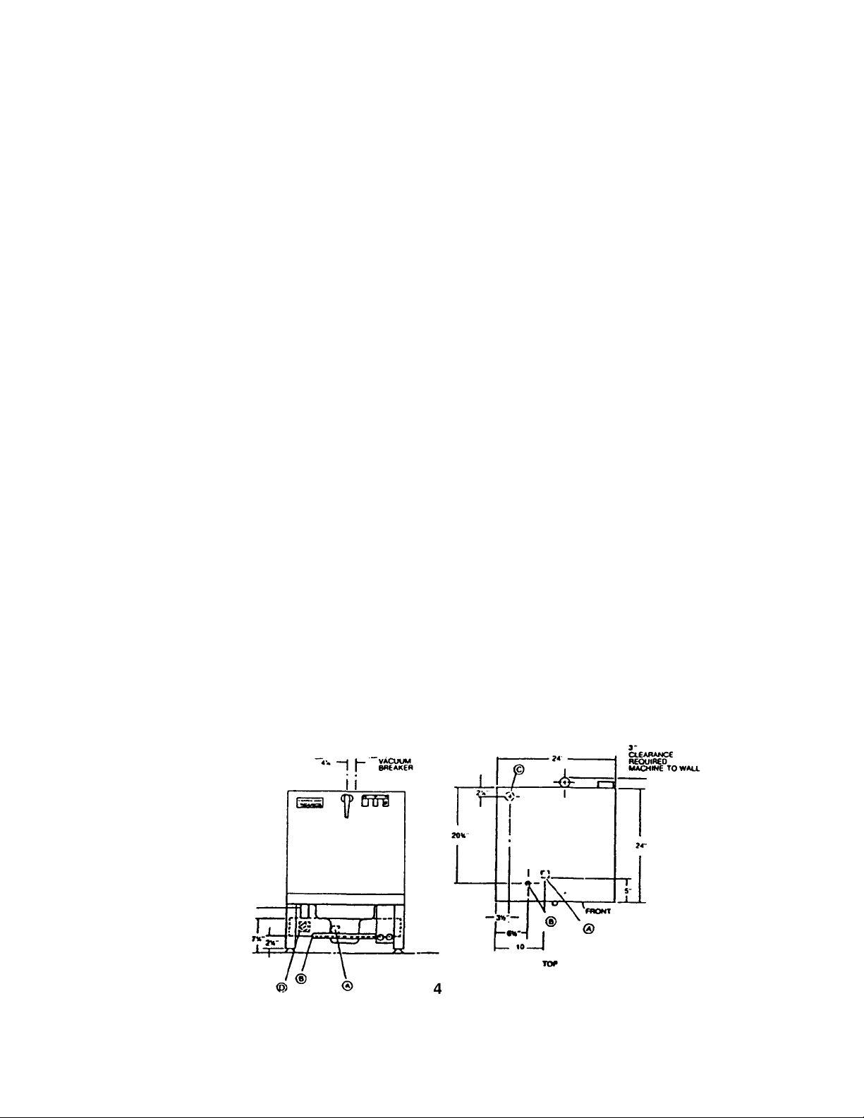
DIMENSIONAL DATA
Reference only
Subject to change
LEGEND
A—ELECTRICAL HOOK UP
B—1/2" F.S.P.S. WATER INLET
C—1 1/2" DRAIN
CONNECTION
D—SANITIZER PUMP
Page 5
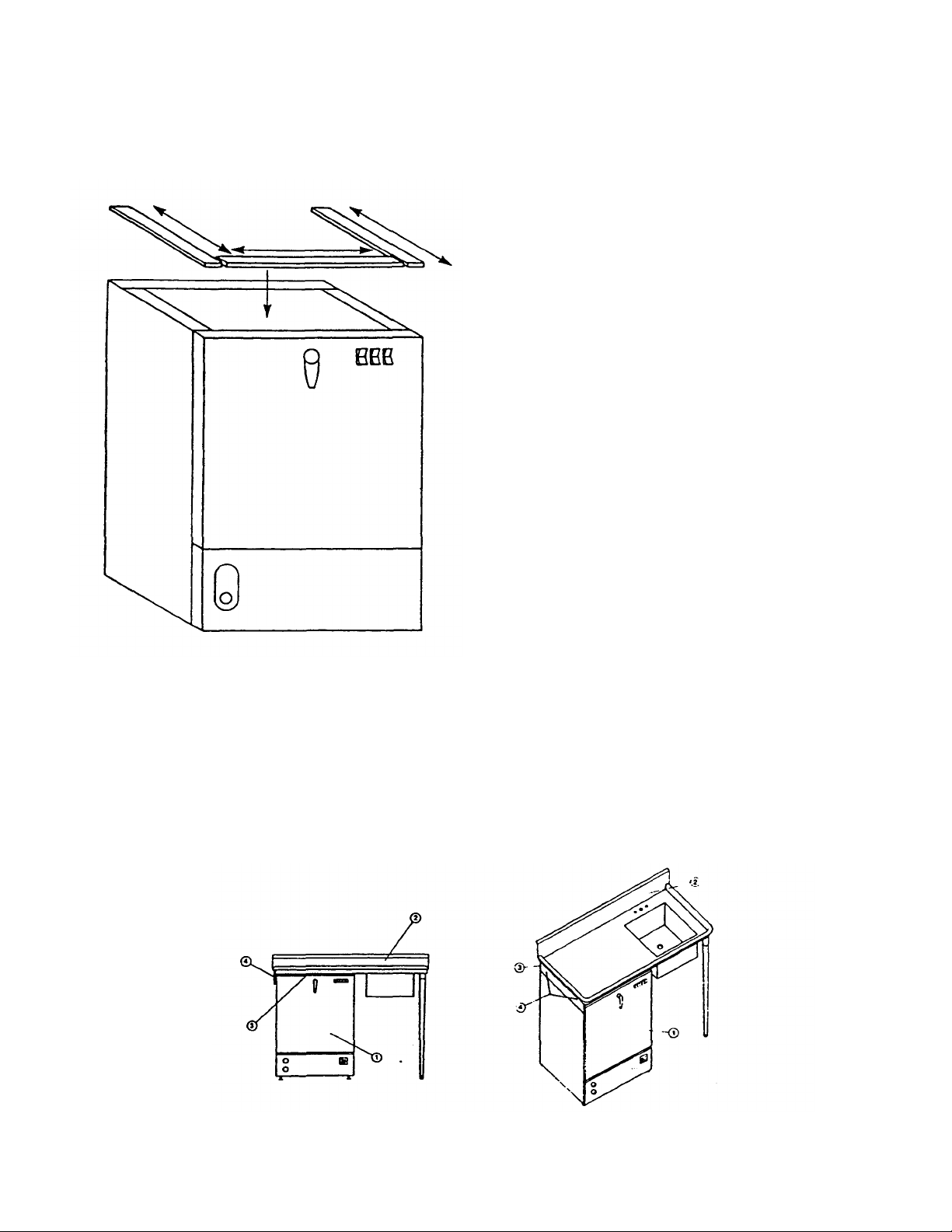
Installation of Model 24LM Top and Table gasket:
These instructions are to be used for applying the adhesive backed sponge rubber strip to the top of the machine
prior to setting the table in place.
Included with the Model 24LM table is a 6' length of 1/4" thick x 1" wide sponge rubber adhesive
backed stripping.
Instructions for applying gasket:
1. Place one end of the stripping along the complete side
of leg support flange and cut it off.
2. Repeat the same procedure along the other side.
3. Place the remaining piece along the front edge and fit it
in between the side pieces and cut it to length.
4. Remove the backing and set the strips in place
Installation of Model 24LM Dishwasher Under Dishtable:
1. On the end of the table, locate bracket #4 opposite the sink end.
2. A rubber gasket #3 is supplied and should be secured to top frame of dishwasher.
3. Place dishtable #2 where it is to be installed and support the machine's end.
4. Slide dishwasher #1 underneath dishtable #2 so that the outside of machine is positioned against the
guide bracket #4. Make sure dishtable and dishwasher are in desired permanent location.
5. Using the two holes in bracket #4 as a guide, drill two holes 9/64" diameter in the side panel of machine.
Note: Drill through first thickness of metal only.
6. Using the self-tapping screws supplied, screw them through bracket #4 and into the side panel of
machine until screws are tight.
Page 6
INSTALLATION INSTRUCTIONS FOR WALL MOUNT DISPENSER UNIT ONLY
1. Supplied with the unit is a wall mounted dispenser unit consisting of three peristaltic pumps mounted inside of a
stainless box with conduit and wires coming from the bottom. With the lower kick plate removed connect the conduit
to the ledge of the unit and connect the plastic connector on the wires to the connector on the timer. This will
provide the power to operate the dispensing pumps from the timer.
2. After the connecting the wires to the timer, mount the box to the selected surface, using the two holes provided in
the rear and with the appropriate fasteners for the application. Consideration for the location of the chemicals and
service of the pumps should be given when selecting a mounting place.
3. Turn the customer's circuit breaker on to the unit and check the electrical connections for the proper readings as
indicated on the machine data plate.
4. Turn on the water to the unit and check for any water leaks. If they check out replace the lower kick plate. If there
are no leaks push the top of the fill switch and hold for approximately 45 seconds.
5. Coming from each dispensing pump in the box is a different colored tube. Above each peristaltic pump in the box is
a primer switch. After making sure that the feeder tubes to the pumps are in their proper containers, as marked on
the pumps, press the switch and hold it until there is a discharge of the fluid into the machine. This is to be done to
each pump before the initial operation of the machine. Water must be in the wash/rinse tub to prevent discoloration
or deterioration of the stainless steel by chemicals.
Removal of Pan Strainer for Cleaning:
(Wash/Rinse Head Assembly must be removed prior to removing strainer.)
1. Drain machine by depressing drain switch for approximately 50 seconds.
2. Remove wing nut from upper pump housing; wash/rinse head may now be lifted out.
3. Pan strainer now accessible; lift out and clean thoroughly.
4. Clean around pump intake with bristle brush.
5. Replace strainer pan.
6. Reinstall wash/rinse head assembly.
7. Clean strainer pan daily or as needed to ensure proper machine operation.
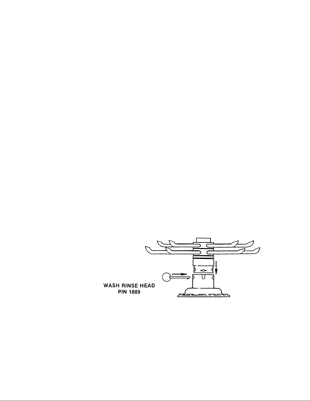
Installation of Wash/Rinse Head Assembly:
(Items disassembled for shipment.)
1. Line holes up on wash head assembly to match slots in pump housing.
2. Insert wash head assembly down into upper pump housing as far as possible.
3. Insert retaining pin to secure wash head to pump housing.
Page 7

INSTALLATION OF TIE DOWN ASSEMBLY FOR CANADIAN STANDARDS
1.
BASE CRADLE
1. Locate the desired floor area in which the unit is going to be installed.
2. Place the base cradle in the exact location the machine will set with the end having the holes drilled in it
to the rear.
3. Mark the holes and then drill two holes 3/8" in diameter, approximately 1-1/2" into the floor, no deeper.
4. Clean any debris out of the holes and place the sleeve anchors with the bolts into the hole. Press them
down and then tighten the nut down so that the anchor fastens firmly into the floor. Back off the nut and
remove it so that approximately 1/2" to 3/4" of the bolt is now a stud sticking up from the level of the
floor.
5. Lay the cradle in place over the studs and seal around the cradle with a silicone rubber sealant.
6. Attach the back panel to the machine by sliding it between the rinse water line and the unit, then
fastening it at the bottom corners to the machine. When the back panel is in place attach the anchoring
bracket loosely to the panel using the elongated slots.
7. Pick the machine up and set it into place on the base cradle. Make sure that the studs through the base
cradle are inserted into the holes in the bottom of the anchoring bracket.
8. Remove the lower front kick panel and level the machine trying to have It a 1/4" higher in the front than
in the back.
9. Once the unit is level fasten the nuts over the studs and tighten to the floor. Next
fasten the bolts and nuts that attach the anchoring bolts to the back panel.
10. When the unit is tightened down and securely in place the remainder of the installation can continue.
2. ANCHORING BRACKET
3. RINSE WATER LINE
4. BACK PANEL
5. ELECTRICAL CONNECTION CUT
OUT
6. INCOMING WATER CONNECTION
PUT OUT
Page 8

GENERAL INSTRUCTIONS
(OPERATION)
Note: Read the following Instructions carefully. Proper operation of your Jackson Dishwasher
will assure clean and sanitized glasses and dishes at optimum efficiency.
Dish Preparation:
1. Scrape dishes thoroughly.
2. Pre-wash dishes by soaking or spraying with hose.
3. Place dishes and cups in dish rack, cups upside down.
4. Place glasses and silverware in combination glass-silverware rack, glasses upside down. Scatter silverware
loosely on bottom.
Note: Silverware in the upright position wash and rinse better than lying flat. These silverware
compartment racks are available through your dealer or service agency.
Operator's Instructions (Standard L/LF Model):
1. Check that pan strainer is clean. Strainer must be clean for proper machine operation (wash/rinse head must
be removed first, then strainer may be removed for cleaning).
2. Place start rocker switch in its center OFF position.
3. Close door and lock latch.
4. Place the sanitizing agent bottle (filled with 5.25% Sodium Hypochlorite) to the left front of machine. Place the
tube coming out of the left side of machine into the sanitizing bottle. The tube must be in the bottle for proper
machine operation. See instructions on separate page of this manual for complete details on sanitizing system.
5. Push top of fill switch and hold for approximately 45 seconds.
6. Open door and slide rack of soiled dishes into machine.
7. Dispense proper amount of detergent in machine.
8. Close and latch door. Start automatic cycle of machine by pushing on top or bottom of start switch; indicating
light will come on.
9. When indicating light goes out, cycle is over; remove clean dishes. Slide in rack of soiled dishes, dispense
proper amount of detergent, close door and push start switch for automatic cycle.
10. At end of mealtime, turn off machine by placing start switch In center position. Drain machine by depressing
drain switch approximately 45-50 seconds. Clean pan strainer and machine.
Detergent Recommendations and Rinse Additives:
We suggest that you contact your local Detergent Specialist for the correct detergent and rinse additives for your
area. To help you until one can be reached, we suggest that you use a non-foaming dishwasher detergent,
approximately one tablespoon in wash tank when machine is filled, and one tablespoon each cycle or load
thereafter. This may have to be increased or decreased to obtain satisfactory results.
When manually dispensing powdered detergent in wash tub always distribute over a sufficient area to prevent
build up. Some detergent when dispensed in a small or concentrated area, may cause deterioration of the
stainless tub or sump.
Page 9

OPERATOR'S INSTRUCTIONS FOR WALL MOUNT DISPENSING UNITS
1. Check that the pan strainer is clean. Strainer must be clean for proper machine
operation (wash/rinse head must be removed first, then strainer may be removed for cleaning).
2. Insert a rack of dishes and then close the door and turn handle.
3. Check the levels of the detergent, rinse additive and sanitizing agent containers. Fill them if
necessary.
4. Push the top of the fill switch and hold it for approximately 45 seconds.
5. Start the automatic cycle of the machine by pushing the top of the start switch and holding for a
count of three. This activates the time cycle and the cycle light will come on. During the cycle the
timer will automatically dispense the detergent, rinse additive, and sanitizer as they are needed.
6. When the cycle light goes out, open the front door and slide out the rack of clean dishes. Replace
them with a rack of soiled dishes and repeat steps #5 and #6.
7. At the end of a mealtime, drain the machine by depressing the drain switch for approximately 4550 seconds. Clean the pan strainer and the machine.
GENERAL INSTRUCTIONS
(PREVENTIVE MAINTENANCE)
THE FOLLOWING IS TO BE PERFORMED AS NEEDED.
Note: Read the following instructions carefully. Proper maintenance of your Jackson
Dishwasher will assure optimum service with a minimum of down time.
1. Remove all lime and corrosion deposits.
a. Fill the machine with wash water as would ordinarily be done for washing.
b. Open door and place one cup or less of de-liming compound into the water. The
compound is available from your detergent supplier.
c. Close door and push start switch.
d. Open door and examine the interior when cycle light goes out. All lime should be
removed and parts should be shiny. If not, scrub stubborn deposits and repeat
operation.
e. After the interior is clean, with door closed, empty the water by depressing drain
swtich for approximately 50 seconds. Refill machine and allow to run through cycle,
then again drain the reservoir. Machine is now ready for normal operation.
2. Clean around overflow strainers and drain hole.
a. Clean around overflow and strainer pan.
b. Clean around pump intake (toothbrush makes excellent tool for cleaning).
3. Clean Y-strainer on incoming water line. (Water and electricity to machine must be
turned OFF for this operation.) a. Remove plug and clean strainer.
4. Clean wash head assembly.
a. By removing the wing nut holding wash/rinse head assembly to pump, wash/rinse
head assembly can be removed.
b. Clean assembly at sink by flushing water through spray jets.
c. If spray jets are still plugged, use sharp object to dislodge and flush again.
d. Reinstall wash/rinse assembly. (See page with instructions.)
5. Clean any deposits which may have built up on exterior moving parts.
a. Clean around door gasket.
b. Using a soft bristle dry brush, clean around switches on exterior of control panel.
(Use no water.)
c. Use soft bristle brush, dip in wash tank water and scrub inside door around gasket
and hinges. Use clean cloth or paper towel to wipe off loose residue.
Page 10

24L CYCLE SEQUENCE CHART
6.
N/A
OPERATOR
1. Push Power Switch
2. Close Door
3. Latch Door Handle
4. Push Fill Switch
5. Push Start Switch
7.
8.
9.
10.
11.
12.
13.
14.
15.
16.
OPERATION
Energizes to Handle Switch
Closes Door Side Switch
Energizes the Machine
Manually Fills Machine
Energizes Timer Motor
Dwell Time
Wash Cycle
Detergent Dispensed
Dwell Time
Drain Cycle
Dwell Time
Fill Cycle
Sanitizer Dispensed
Rinse Additive Dispensed
Rinse Cycle
TIME SECONDS
The rinse water used in the previous cycle will be used as the wash water in the next cycle. Each
cycle is one revolution.
REMOVAL of WASH/RINSE HEAD
ASSEMBLY
N/A
N/A
N/A
38-42
N/A
4-7
57-63
7-9
4-7
35-40
4-7
38-43
8-14
5-10
38-43
(GENERAL INSTRUCTIONS)
1. Before opening the door, hold the drain switch in and drain all of the water out of the unit.
2. Open the door and allow the unit a few minutes to cool off.
3. With your fingers, loosen the wing nut on the wash head assembly and lift it up and out. Take it to a
safe place and begin to disassemble it according to the following instructions.
4. Locate Allen head set screw in the wash head cap, insert Allen wrench and loosen screw by turning
counterclockwise.
5. Turn wash head cap counterclockwise until cap is removed and put cap in safe place.
6. Remove 1/4" stainless ball bearings carefully and put it in a receptacle in a safe place.
7. Lift and remove small manifold with short tubes. Put it in a safe place.
8. Remove 1/4" ball bearing in similar method to step #6.
9. Lift and remove large manifold with large length tubes simitar to step #7.
10. The lower fixed race may be left in place.
11. Clean ball bearings by soaking in de-liming solution.
12. Ball bearing race ways may be cleaned by either brushing with de-liming solution (toothbrush makes
excellent tool) or gently clean by rubbing with fine sandpaper or emery cloth.
13. Rinse ball bearings and manifolds thoroughly.
14. To reassemble, first fill lower race to capacity with 1/4" ball bearings, then remove one. This will give
proper movement needed during rotation of assembly.
15. Replace lower manifold and fill race fully with 1/4" ball bearings. Repeat, removing one only.
16. Replace upper manifolds and repeat necessary parts of step #14.
17. Replace wash cap by screwing on center shaft clockwise, finger tight.
18. Back off wash cap about 1/4 turn and tighten Allen set screw.
19. Rotate manifolds in opposite directions; see if they rotate freely. A rule of thumb is to select the
longest tube in the bottom manifold and make sure it moves up and down at least 1/8" and no more
than 1/4".
20. Close the front door and refill dishwasher.
21. Run through several cycles and recheck wash arms for easy movement. Adjust If necessary.
Page 11
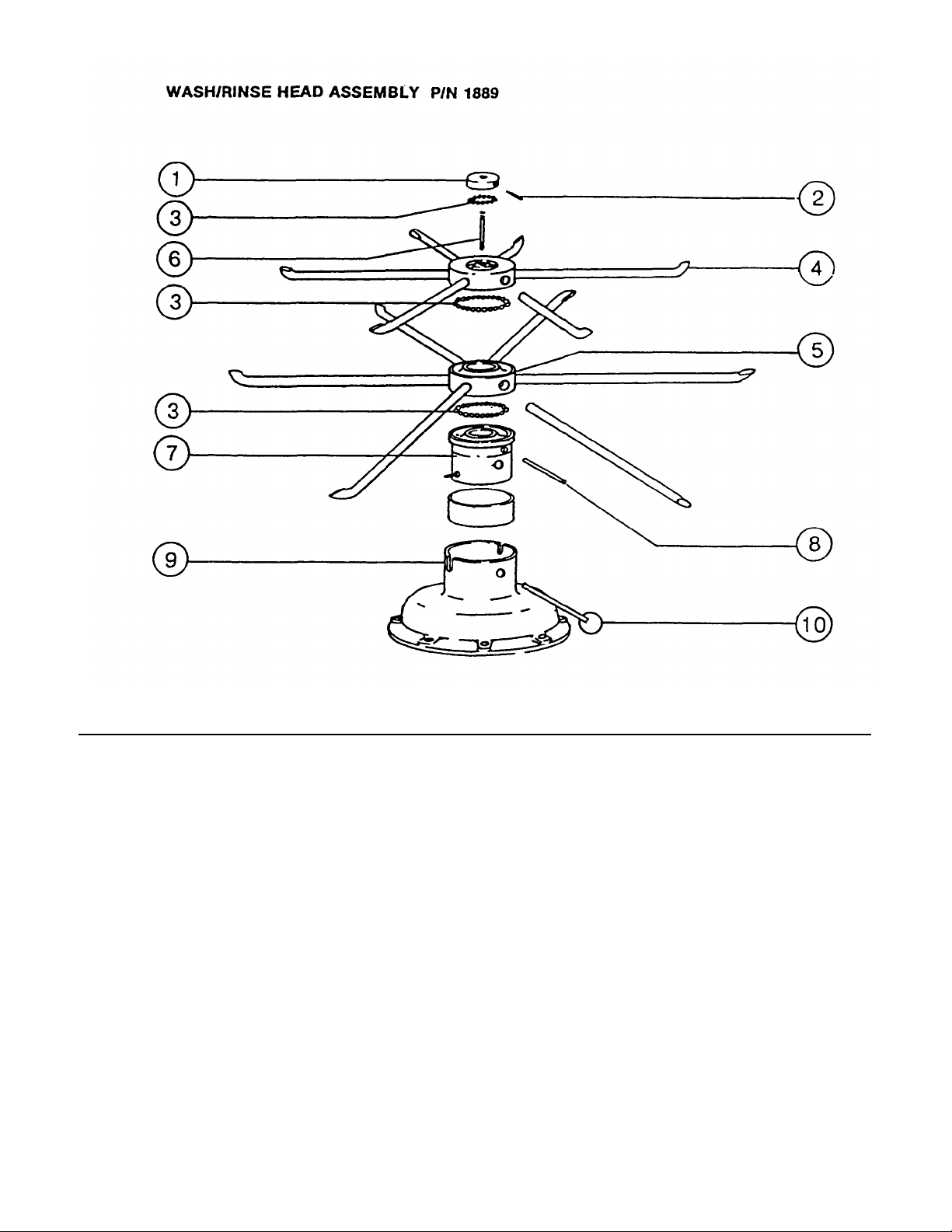
ITEM P/N DESCRIPTION ITEM P/N DESCRIPTION
1. 1865 WASH HEAD CAP WITH RACE 6. 1875 WASH HEAD CENTER SHAFT
2. 1870 WASH HEAD CAP SET SCREW 7. 1936 WASH HEAD FIXED RACE
3. 1940 WASH HEAD BEARING 1/4 " S/S 8. 1886 WASH HEAD SHAFT HOLDING PIN
4. 1890 WASH HEAD SMALL MANIFOLD 9. 1096 UPPER PUMP HOUSING
w/TUBES 10. 1898E WASH HEAD ASSEMBLY
5. 1895 WASH HEAD LARGE MANIFOLD
wfTUBES
RETAINING PIN w/RING
Page 12

TIMER for MODEL 24L
General Description:
The timer is a self-contained (frame mounted) timer of the repeating cycle type. It is mounted on the lower control
panel of the Jackson Dishwashing Machine to control the automatic functions of this machine. It consists of a
clock motor which operates on 60 cycle, 110VAC. In addition to the clock motor, the timer also contains a driven
cam arrangement which operates five micro switches.
Principle of Operation:
The timer controls various operations of the automatic washers as per wiring diagram for each machine; however,
the timing cycle and the micro switches are the same for each model. The time for One Complete Revolution of the
cam shaft is approximately 360 seconds, allowing two wash and two rinse operations for each complete revolution
of the cam shaft. The micro switch nearest the timer motor is the hold circuit and uses both the NO and NC
contacts. The micro switch second from the timer motor controls the wash/rinse and uses the NC contact. The
micro switch third from the timer motor controls the rinse/fill and uses just the NC contact. The micro switch fourth
from the timer motor controls the drain and uses just the NC contact. The last micro switch, fifth from the timer
motor, controls the sanitizing pump and uses just the NC contact.
Service Instructions:
CAUTION: Always remove the power to the machine before working on the control panel or while servicing
the components in the door panel. All electrical checks should be made by qualified personnel.
Timer operation can be observed after removing the machine's kickplate by loosening the two screws holding it.
If it is determined that the timer is defective, it is recommended that a new timer be installed. If a new timer is not
available, limited field maintenance can be accomplished by changing the micro switch.
A frozen contact on a micro switch will be indicated by one function being executed all the time or the absence of a
click when the switch arm is actuated.
To Replace Micro Switch:
1. Remove all wires from the timer, properly tag them to assure proper replacement.
2. Remove the screws which hold the timer to the control panel.
3. One screw holds the micro switches, cams and actuating arms in the frame. This screw is seen on the
side opposite the motor. Remove this screw. Note: Be sure to note which cam goes with which micro
switch. Cam nearest timer motor has 1/2 raised and 1/2 depressed edge.
4. The unit can now be taken apart and the defective micro switch replaced.
5. Reassemble.
Note: The flanges on the cams are such that they only mesh in one direction.
The timers cam drive system is equipped with a clutch to enable one to view the operations of the cams
and micro switches. Remove power to machine before touching timer. Rotate cams by turning with fingers;
cams will turn in one direction only. Do not force them. As cams actuate switches, listen for the 'click' of
the switch or test the switches with an ohmmeter.
Page 13

TIMER for MODEL 24L
WALL MOUNT DISPENSING SYSTEMS
General Description:
The timer is a self-contained (frame mounted) timer of the repeating cycle type. It is mounted on the lower control
panel of the Jackson Dishwashing Machine to control the automatic functions of this machine. It consists of a clock
motor which operates on 60 cycle, 110VAC. In addition to the clock motor, the timer also contains a driven cam
arrangement which operates seven micro switches.
Principle of Operation:
The timer controls various operations of the automatic washers as per wiring diagram for each machine; however,
the timing cycle and the micro switches are the same for each model. The time for One Complete Revolution of the
cam shaft is approximately 180 seconds, allowing one wash and one rinse operation for the complete revolution of
the cam shaft. The Micro Switch nearest the timer motor is the hold circuit. The Micro Switch second from the timer
motor controls the wash/rinse cycle. The Micro Switch third from the timer motor controls the detergent dispensing
cam. The Micro Switch fourth from the timer motor controls the drain cycle cam. The Micro Switch fifth from the
timer motor controls the water fill solenoid cam. The Micro Switch sixth from the timer motor controls the rinse
additive dispensing cam. The Micro Switch seventh from the timer motor controls the sanitizer agent cam.
Service Instructions:
CAUTION: Always remove the power to the machine before working on the control panel or while servicing
the components in the door panel. All electrical checks should be made by qualified personnel.
Timer operation can be observed after removing the machine's kickplate by loosening the two screws holding it.
If it is determined that the timer is defective, it is recommended that a new timer be installed. If a new timer is not
available, limited field maintenance can be accomplished by changing the micro switch.
A frozen contact on a micro switch will be indicated by one function being executed all the time or the absence
of a click when the switch arm is activated.
To Replace Micro Switch:
1. Remove all wires from the timer, properly tag them to assure proper replacement.
2. Remove the screws which hold the timer to the control panel.
3. One screw holds the micro switches, cams and actuating arms in the frame. This screw is seen on the
side opposite the motor. Remove this screw.
4. The unit can now be taken apart and the defective micro switch replaced.
5. Reassemble.
Note: The flanges on the cams are such that they only mesh in one direction.
The timers cam drive system is equipped with a clutch to enable one to view the operations of the cams
and micro switches. Remove power to machine before touching timer. Rotate cams by turning with fingers;
cams will turn in one direction only. Do not force them. As cams actuate switches, listen for the 'click' of
the switch or test the switches with an ohmmeter.
Page 14

TIMER MOTOR and
ADJUSTMENT to CAMS
(FOR WALL MOUNT DISPENSING SYSTEMS)
CAUTION: Always remove the power to the machine before working on the control panel or while
servicing the components In the door panel. All electrical checks should be made by qualified
personnel.
A defective motor is indicated by the fact that the cams do not rotate or the machine does not perform the
automatic operations, or performs a specific part of the cycle continuously, but works okay on manual. Remember,
the timer motor is controlled by the start switch and the hold micro switch; check this complete circuit before
changing motor.
To Replace Motor
1. Remove motor leads from shorting bar and neutral.
2. Remove the two screws which hold the motor.
3. Replace with a new motor.
Note: It may be necessary to remove complete timer to replace motor; If so, follow steps 1
and 2 on previous page.
1. TIMER MOTOR
2. TIMER MOTOR CAM (F)
3. WASH MOTOR CAM (F)
4. DETERGENT CAM (A)
5. DRAIN CAM (F)
6. WATER FILL CAM (A)
7. RINSE ADDITIVE CAM (A)
8. SANITIZING AGENT CAM (A)
F -FIXED CAM
A
-ADJUSTABLE CAM
When making adjustments to the timer cams, be sure that the first cam next to the timer motor is in its
stop position in the notch. Place one hand over the timer motor with your thumb lodged next to or on the
first cam so that it will not move when the other cams are being adjusted. To make the adjustment, place
your other thumb on the right side of the cam. If a longer operating time is desired. Increase the gap
between the left and right side of the cam. If a shorter operating time Is desired, decrease the gap
between the left and right side of the cam.
Page 15

DEFECTIVE MOTOR
A— TO UPPER RIGHT TERMINAL START SWITCH
CAUTION: Always remove the power to the machine before working on the control panel or while
servicing the components In the door panel. All electrical checks should be made by
qualified personnel.
A defective motor Is indicated by the fact that the cams do not rotate or the machine does not perform the
automatic operations, or performs a specific part of the cycle continuously, but works okay on manual.
Remember, the timer motor is controlled by the start switch and the hold micro switch; check this complete
circuit before changing motor.
To Replace Motor
1. Remove motor leads from shorting bar and neutral.
2. Remove the two screws which hold the motor.
3. Replace with a new motor.
Note: It may be necessary to remove complete timer to replace motor; if so, follow steps 1 and 2
on previous page.
B— TO LOWER RIGHT TERMINAL START SWITCH
C— TO DRAIN RELAY TERMINAL
D— LOWER TERMINAL ON FILL SWITCH
E— TO NEUTRAL TERMINAL
F— SHORTING BAR CONNECTED TO ALL
FIVE TIMER SWITCHES, THIS
TERMINAL ON REAR
G— TO COIL ON DRAIN RELAY
H— TO UPPER LEFT TERMINAL FILL SWITCH
Page 16

REPLACEMENT of SWITCHES
1.
CONNECTION TERMINALS
in FRONT DOOR
There are three switches installed in the door's upper right hand corner. These are the start, drain, and fill.
Before working on the machine, it is important that the power be turned OFF at the customer's circuit breaker
to prevent the possibility of electrical shock; trip the breaker to the OFF position.
Remove inside door from machine by removing the eight screws on the flanged section of the inside door
panel. The three switches are all snapped into place in individual rectangular holes. By using a screw driver, it
is possible to pry up the chromed flange on each side away from switch and remove the switch from flange.
Little pressure should be used to prevent damage of switch and flange.
After the switch has been checked to see if it is defective, replacement can be made by placing the new switch
close to the defective switch and moving one wire at a time, transferring them to the same terminals on the
new switch until all wires have been reconnected. If this is not practical, pull the wires loose, one at a time, tag
them and reconnect them according to the electrical diagram.
Put all switches back into place making sure switch protrudes through front door properly.
Note: Two click positions on bracket. Replace inner door panel. Seal top of inner door to outer door with a
waterproof sealant. Power can now be applied to the dishwasher and run through cycles, checking
all operations.
2. BRACKET SPRING SIDES
3. PANEL PLATE
4. BRACKET FRONT
5. ROCKER BUTTON
INTERLOCK SYSTEM
The Interlock System is designed to prevent the machine from operating when the front door is opened or not
latched properly.
The Interlock System consists of two safety switches, one mounted so that the door latch has to be closed to
complete the circuit. The other switch is located so that a pin on the machine depresses a safety switch
mounted on the door, to complete the circuit. Either of these switches, if not depressed, will prevent the
machine from operating. Basically, the door must be closed and the door latch locked in order for the machine
to function.
DOOR SAFETY SWITCH (SIDE) P/N 1641 DOOR LATCH SAFETY SWITCH P/N 1641
Page 17

CHECKOUT
(INTERLOCK SYSTEM)
Note: All electrical checks should be made by qualified service personnel.
If it is determined that the proper power is being applied to the machine's incoming terminal
blocks, then further check of the interlock system should be made.
Note: This checkout would only be performed if none of the systems of the machine
operate. This would mean that none of the switches, when depressed, will perform
the function noted for that switch.
Example: Drain, fill, start switches.
Proceed with checkout.
1. Remove power to the machine by turning circuit breaker that protects the machine to OFF position.
Note: It may be necessary to disconnect the door springs to prevent door from closing when inner
door is removed.
2. Open the front door and remove screws holding inner panel of door.
3. Disconnect one wire from the switch closest to the door latch and using an ohmmeter, depress the lever of the
switch and check that there is continuity across that switch. If there is no continuity, replace switch.
4. Check second safety switch located in top right hand corner of door, viewed with inner door off. Remove wire
from one side of the switch and check for continuity with ohmmeter when switch is depressed. If there is no
continuity, replace switch.
5. Replace inner door panel.
6. Apply power and check operation.
Page 18

OPERATOR CONTROLS
The operator of this machine has only three control switches which he can operate. These switches are
located in the top righthand corner of the machine's front door.
1. The Start Switch initiates automatic operation of the machine.
2. The Drain Switch allows the User to manually drain the wash tank at the end of the day or when cleaning is
required.
3. The Fill Switch allows the User to manually fill the machine before running it the first time of each day. a.
Also used as the Primer Switch for the sanitizing agent pump.
SEQUENCE of MACHINE
OPERATIONS
1. Start switch depressed.
2. Timer motor activated.
3. Wash/rinse cam switch activates motor starting relay for wash.
4. Wash ends — drain cam switch activates drain relay and motor starting relay for drain.
5. Drain ends — fill solenoid and sanitizing agent pump activated (dropping sanitizing
agent in rinse water) by fill cam switch.
6. Wash/rinse cam switch activates motor starting relay for rinse; fill ends.
7. Timer motor deactivated and cycle ends.
Page 19

OPERATOR CONTROLS FOR WALL MOUNT
DISPENSING SYSTEMS
The operator of this machine has six control switches which he can operate. Three of these switches are located in
the top righthand corner of the machine's front door and the remainder, in the dispenser box.
1. The Start Switch initiates automatic operation of the machine.
2. The Drain Switch allows the User to manually drain the wash tank at the end of the day or when cleaning is
required.
3. The Fill Switch allows the User to manually fill the machine before running it the first time of each day.
4. The primer switches in the dispenser boxes are used to activate the peristaltic pumps for purposes of refilling
the lines after a change in chemical containers.
5. The indicator light is either located in the start switch or just to the right of the switches.
SEQUENCE of MACHINE
OPERATIONS
1. Start switch depressed.
2. Timer motor activated.
3. Wash/rinse cam switch activates motor starting relay for wash.
4. The detergent dispenser pump is activated by the timer dispensing detergent into the
wash water.
5. Wash ends — drain cam switch activates drain relay and motor starting relay for drain.
6. Drain ends — fill solenoid and sanitizing agent pump activated (dropping sanitizing agent
in rinse water) by the till cam and sani-pump switch of timer.
7. Wash/rinse cam switch activates motor starting relay for rinse; fill ends.
8. The rinse additive pump is activated by the timer dispensing rinse additive into the rinse
water.
9. Timer motor deactivated and cycle ends.
19
Page 20

PERISTALTIC PUMP SANITIZING
DISPENSING SYSTEM
(FOR WALL MOUNT DISPENSING SYSTEMS)
The three peristaltic pumps are mounted in the dispenser box which is attached to the wall or
unit. The pump receive their electrical signals from two sources.
The first source is the rinse/fill switch which is used to prime the pump when it is first put into
operation and then every time the unit Is filled with fresh water to start a new meal period.
The second source is the timer which activates the pump during the fill cycle of the unit and
allows it to drop 15 milliliters of sanitizing solution into the rinse water.
Checkout of Sanitizing Agent Injector
The pump can be deemed operational if the following items are observed:
1. If the cam roller assembly rotates during each cycle.
2. If the solution is observed passing through the tube.
Note: Both of these operations must be observed to determine if the sanitizing agent is
being dispensed.
It it is determined that the unit is not operating correctly, the following procedures will aid in
correcting the problem:
1. Make certain that the tube is in the bottle of solution.
2. Make certain that there are no cracks in the tubing and particularly in the pump hose.
3. Check all wire connections on the pump, the timer cam, and the rinse/fill switch.
4. Check to see that there is no debris in the tubes.
5. Make sure that the tubing is inserted into the pump hose so that air is not drawn into the
system.
ITEM P/N DESCRIPTION
1. 1543 PRIMER SWITCHES
2. 465 PERISTALTIC PUMPS
3. 465D CAM ROLLERS
4. 465F INTAKE HOSE
5. 4652 OUTLET TUBE
20
Page 21

PERISTALTIC PUMP SANITIZING
DISPENSING SYSTEM
(OPERATION)
The three peristaltic pumps are mounted in the dispenser box which is attached to the wall or unit. The pump
receive their electrical signals from two sources.
The first source is the rinse/fill switch which is used to prime the pump when it is first put into operation and then
every time the unit is filled with fresh water to start a new meal period.
The second source is the timer which activates the pump during the fill cycle of the unit and allows it to drop 15
milliliters of sanitizing solution into the rinse water.
Checkout
of Sanitizing Agent Injector The pump can
be deemed operational if the following items are observed:
1. If the cam roller assembly rotates during each cycle.
2. If the solution is observed passing through the tube.
Note: Both of these operations must be observed to determine if the sanitizing agent is being
dispensed.
It it is determined that the unit is not operating correctly, the following procedures will aid in correcting the problem:
1. Make certain that the tube is in the bottle of solution.
2. Make certain that there are no cracks in the tubing and particularly in the pump hose.
3. Check all wire connections on the pump, the timer cam, and the rinse/fill switch.
4. Check to see that there is no debris in the tubes.
5. Make sure that the tubing is inserted into the pump hose so that air is not drawn into the system.
Instructions: Filling the Storage Bottle and Dispenser Operation.
1. Check the level of the liquid in the opaque storage bottle setting in front of or on the side of the machine. You
should be able to see liquid about 1" up from the bottom.
2. To refill, place a funnel in the top of the bottle and slowly transfer 5.25% of Sodium Hypochlorite (FDA approved)
into the storage bottle.
CAUTION: Do not spill liquid on clothes or skin and avoid getting in eyes, as it is an
irritant. Rinse immediately. Harmful if swallowed; call a physician immediately.
3. Replace the storage bottle in front or on the side with the hose in the mouth of the bottle.
21
Page 22

P/N 465 COMPLETE PUMP ASSEMBLY
ITEM P/N DESCRIPTION ITEM P/N DESCRIPTION
1. 465A PUMP MOTOR 8. 465H FACE PLATE
2. 465B PUMP HOUSING 9. 465I PLATE MOUNTING
3. 465C HOUSING MOUNTING BOLTS
(3) 10/32 FILLSTER HEAD
4. 465 D CAM ROLLER ASSEMBLY
5. 465E CAM ROLLER SET SCREW 11. 465J OUTPUT OR INJECTION
6. 465 F PUMP HOSE
7. 465G HOSE CLAMPS (2)
10. 465J INTAKE OR SUCTION
22
SCREWS (4) 8/32
TUBING
TUBING
Page 23

SERVICE INSTRUCTIONS
(INCOMING WATER SOLENOID VALVE)
SOLENOID VALVE P/N 1420
To Take The Valve Apart:
Disassembly — These valves may be taken apart by
unscrewing the bonnet and the enclosing tube
assembly from the valve body assembly. See Fig. 3.
After unscrewing, carefully lift off the bonnet and
enclosing tube assembly. Don't drop the plunger.
The "0" ring seal and diaphragm cartridge can now
be lifted out.
Be careful not to damage the machined faces while
the valve is apart.
To Reassemble — Place the diaphragm cartridge in
the body with the pilot port extension UP. Hold the
plunger with the synthetic seat against the pilot port.
Make sure the "0" ring is in place, then lower the
bonnet and enclosing tube assembly over the
plunger. Screw bonnet assembly snugly down on the
body assembly.
Possible Problems:
Pilot Port extension #1 clogged. Hole #2
clogged.
Remedy:
Pass heated straight pin through hole #2 or
clean hole #1.
23
Page 24

SEAL and CERAMIC for
1.
MOTOR
PUMP SYSTEM
(GENERAL INFORMATION)
The wash and drain pump are part of the total motor pump system. One seal and ceramic are utilized to
prevent the pump from leaking.
Replacement of Seal and/or Ceramic:
1. Drain machine either by depressing drain switch or by baiting out.
2. Turn incoming power to machine OFF.
3. Open door — remove racks, wash/rinse head assembly and strainer pan.
4. Remove kickplate (located under front door).
5. Unplug motor at connector.
6. Loosen eight screws holding pump in sump tank.
7. Disconnect drain hose from motor (must be done from underneath machine).
8. Pull motor and pump gently upward and move from side to side as required to remove unit. (Old
machines motor removed downward.)
9. Set pump and motor on bench and proceed.
10. Loosen eight screws holding upper pump housing, and remove housing.
11. Remove diffuser plate.
12. Loosen impeller screw and remove impeller.
13. Remove suction adapter plate.
14. Remove drain inlet plate.
15. Remove propeller.
16. Remove mounting plate from motor (loosen 4 phillips head screws on bottom of plate).
17. Knock out old seal carefully and clean hole, re-insert new seal.
Note: Be sure not to ruffle edges of seal when inserting. Seal should contact all resting
surfaces at one time.
18. Ceramic is imbedded in propeller and normally does not wear or need replacement, but check for cracks.
19. Reinstall motor and pump by reversing above process.
2. MOUNTING PLATE
3. STATIONARY SEAL
4. SHIM WASHERS ON
MOTOR SHAFT
5. CERAMIC
6. DRAIN PROPELLER
24
Page 25

TROUBLE SHOOTING GUIDE
PROBLEM CAUSE SOLUTION
Water overflow out bottom of 1. Machine not level. 1. Level machine, slight tilt
front door when wash pump
is operating. 2. Overflow drain clogged. 2. Remove obstruction, checking
3. Water level in machine's 3. Solenoid valve not closing at
wash reservoir too high. end of fill or rinse cycle
4. Detergent foaming. 4. Reduce quantity of detergent.
Wash/rinse motor runs 1. Wires broken or loose. 1. Check all wires in the motor
but kicks out or stops
after several seconds. 2. Pump bound up. 2. Disassemble and free pump.
3. Bad bearing, noticeable by 3. Replace.
noisy bearings or locked
drive shaft.
4. Defective motor starting 4. Replace.
relay. (Typical • motor
hums.)
Note: The motor starting relay is utilized to insert a starting field in the wash pump motor, once the motor has
gained speed; the running winding will then take over and the starting winding will be removed when the
relay kicks out. This relay is the amperage sensing type.
Motor doesn't operate on 1. Defective wash/rinse micro 1. Replace switch.
automatic (rinse operates switch of timer.
okay on automatic cycles). 2. Broken or loose wires. 2. Repair or reconnect.
No water comes through the 1. Hand water valve to machine 1. Turn on water valve.
fill pipe when the fill not turned on.
switch is depressed.
2. Defective coil on 2. Replace coil.
solenoid valve.
3. Broken or loose wires. 3. Repair or reconnect.
4. Defective manual fill switch. 4. Replace.
Little or no water coming 1. Defective flow regulator. 1. Replace.
through fill pipe and wash-
rinse pump surges. 2. Water leaving machine 2. Clean or replace drain valve.
through drain valve.
3. Water pressure low. 3. Correct pressure problem or
Fill doesn't operate on auto 1. Fill micro switch defective 1. Replace.
matic during timed cycle (but (this is the center micro
does operate on manual fill switch).
operation).
2. Fill switch defective 2. Replace.
on NC contacts.
3. Broken or loose wire. 3. Repair or reconnect.
25
to rear.
inside of machine first.
causing excessive water level
problem.
and reconnect as necessary.
increase pipe size to machine.
Water should flow at the rate
of 4 gallons per minute (2.7
gallons in 40 seconds).
Page 26

TROUBLE SHOOTING GUIDE
ssive water line pressure can cause water to continually run even though the power to the machine is
PROBLEM CAUSE SOLUTION
Fill water runs continuously 1. Defective plunger in 1. Replace plunger.
with circuit breaker controlling solenoid valve.
machine turned off. 2. Defective diaphragm in 2. Check holes in diaphragm
Note: In disassembling or checking solenoid valve, use instructions shown on separate page.
Fill water runs continuously 1. Defective fill switch. 1. Replace.
with power applied to machine,
but when circuit breaker 2. Defective timer that has 2. Replace timer motor or timer
to machine is turned off, stopped in a position as necessary.
water stops. keeping the rinse on.
Note: Exce
Wash temperature not at 1. Defective thermometer. 1. Using a thermometer (fast
required reading on
thermometer.
Rinse water not at required 1. Thermometer's defective. 1. Replace.
temperature range.
After filling machine with 1. Overflow drain clogged. 1. Clean away obstruction.
water, leakage began at
lower front panel without
machine operating or at
end of rinse cycle. 2. Fill switch activated too 2. Activate fill switch no more
long. than 40 seconds.
26
solenoid valve. cartridge to insure that they are
3. Defective fill micro switch on 3. Replace.
timer assembly.
turned off. Check specifications for required pressure.
2. Incoming fill water tem 2. Check out hot water tank
perature not as required, supplying machine, correct
causing wash or rinse tem- supply temperature.
perature to be lowered
during cycle.
3. Unit sets too long 3. Drain and refill before cycling.
between operations.
2. Incoming fill water to 2. Check hot water tank
machine not up to tem- supplying machine, correct
perature 120 º-140º F. supply temperature.
open. The one on the outside
perimeter should be the size of
an ordinary straight pin. if it's
not, heat a straight pin and put
it through this hole to enlarge.
If this fails to correct situation,
replace diaphragm.
reading type that's known to be
correct), insert in wash
reservoir and check reading
against wash thermometer on
machine. If machine ther
mometer isn't correct within 3
or 4 degrees, replace.
(Water should be below over
flow by at least 1".)
Page 27

TROUBLE SHOOTING GUIDE
PROBLEM CAUSE SOLUTION
Machine doesn't drain when 1. Drain solenoid clogged. 1. Remove obstruction.
drain switch Is depressed.
Note: The drain pump of this machine is part of wash motor, so If wash motor operates properly
Level of sanitizing agent 1. Faulty sanitizing agent 1. Check, using instruction
does not change. pump. page on sanitizing agent
Cam roller assembly 1. Faulty motor. 1. Replace motor.
on peristaltic pump 2. Faulty timer micro switch. 2. Replace micro switch.
does not rotate. 3. Tube is bunched up in 3. Straighten out hose and
2. Defective drain switch. 2. Replace.
3. Defective motor or 3. Replace.
motor start relay.
4. Defective drain solenoid. 4. Replace.
5. Defective motor reversing 5. Replace.
relay.
6. Broken or loose wire. 6. Repair or reconnect.
drain system should work; but check windings.
2. Suction hose (intake tube) 2. Return to bottle.
out of supply bottle.
3. Pinch tube cracked and 3. Replace pinch tube.
drawing air.
housing. place clamp on intake side o
pump.
hose closer to the housing.
27
Page 28

FRONT VIEW OF MACHINE
ITEM P/N DESCRIPTION
1. 512 DOOR HANDLE ASSEMBLY
2.
3. 492 FRONT DOOR
4. 1889 WASH/RINSE ASSEMBLY
5. 1420 SOLENOID (FILL)
6. 553 FLOW CONTROL
7. 1536 "Y" STRAINER
8. 303 ELECTRICAL CONTROL PANEL
9. 1251 UPPER RINSE HEAD ASSEMBLY
10.
11. DISPENSER FEED TUBES UNITS ONLY
12.
SWITCHES — DRAIN, FILL. START
MOUNTING PLATE
REMOTE MOUNTING OF
DISPENSER INTAKE TUBES
Page 29

BACK VIEW OF MACHINE
ITEM P/N DESCRIPTION
1. INCOMING WATER CONNECTION
2. 1841 VACUUM BREAKER ASSEMBLY
3. EQUALIZING VENT
4. DRAIN — GRAVITY FEED
5. 1081 PUMP & MOTOR ASSEMBLY
29
Page 30

LEFT SIDE VIEW OF MACHINE
7.
1081
ITEM
1.
2.
3.
4.
5.
6.
8.
9.
10.
11.
P/N
1841
512
492
549A
834
1424
DESCRIPTION
VACUUM BREAKER ASSEMBLY
DOOR HANDLE ASSEMBLY
FRONT DOOR, OUTER
KICK PANEL
INCOMING WATER • 120º • 140º F
ADJUSTING FEET (4 PLACES)
MOTOR
DRAIN - GRAVITY FEED
DRAIN SOLENOID VALVE
SIDE FRAME & BRACE
FITTINGS FOR DISPENSER INTAKE
30
Page 31

RIGHT SIDE VIEW OF MACHINE
ITEM P/N DESCRIPTION
1. 1841 VACUUM BREAKER ASSEMBLY
2. 1889 WASH/RINSE ASSEMBLY
3. SIDE FRAME & BRACE
4. 834 ADJUSTING FEET
5. 549A KICK PANEL
6. 492 FRONT DOOR
7. 512 DOOR HANDLE ASSEMBLY
8. 547 OPTIONAL TOP
31
Page 32

BOTTOM VIEW OF MACHINE
ITEM P/N DESCRIPTION
1. 1081 PUMP MOTOR (WASH — RINSE)
2. 536 DRAIN HOSES
3.
4. 1424 DRAIN VALVE
5. 1691 THERMOMETER
6. 1536 "Y" STRAINER
7. 553 FLOW CONTROL
8. 1420 SOLENOID — FRESH WATER
OVERFLOW DRAIN — GRAVITY FEED
32
Page 33

ITEM P/N DESCRIPTION
1. 1536 "Y" STRAINER
2.
3. 553 FLOW CONTROL
4. 1420 SOLENOID VALVE 1/2"
5. PIPE UNION
REMOVEABLE FILTER
33
Page 34

PUMP AND M0TOR ASSEMBLY
ITEM
P/N
1.
2.
1085
3. 1085 STATIONARY SEAL ASSEMBLY
4. 1085 SHIM WASHERS
5. 1085 ROTATING CERAMIC
6. 1085 PROPELLER FOR DRAIN PUMP
7. 1085 "O" RING SEAL
8. 1085 DRAIN INLET PLATE
9. 1095 SUCTION ADAPTER PLATE
10. 1090 IMPELLER FOR WASH PUMP
11. 1085 TRUSS HEAD SCREW
12. 1095 DIFFUSER (ALSO 1087)
13. 1095 UPPER PUMP HOUSING (ALSO 1096)
14.
15.
16.
17. 1897 WING NUT
DESCRIPTION
MOTOR
MOUNTING PLATE
WASH HEAD BOTTOM ADAPTER COMES w/ 0193600
FILL HEAD MACHINE SCREW (SHORT)
FILL HEAD MACHINE SCREW (LONG)
Page 35

ITEM P/N DESCRIPTION
1. 1691 THERMOMETER
2. 1665 TERMINAL BOARD
3. GROUNDING LUG
4. 1207 MOTOR STARTING RELAY
5. 1246 DRAIN RELAY (MOTOR REVERSING)
6. 1713 TIMER
7. 460 SANITIZING PUMP (L/LF MODELS ONLY)
(LOCATED BEHIND BRACKET)
8. 1213 MOTOR RELAY
35
Page 36

1.
GAUGE
WASH/RINSE HEAD ASSEMBLY LOCATED
ITEM P/N DESCRIPTION
1. 1889 WASH ASSEMBLY
2. WASH RESERVOIR
36
2. BRACKET
3. NUTS
Page 37

NOTE:
ALL NEUTRAL WIRES “WHITE”
ALL GROUND WIRES “GREEN”
ALL OTHER WIRES “RED”
Page 38

COMPLETE PARTS LIST for 24L
303 Control Panel, wired (lower front) for 24L 1
447 Door Handle Cam Nut 2
465 Dispenser Peristaltic Pump, Complete 1
465A Dispenser Peristaltic Pump Motor 1
465B Dispenser Peristaltic Pump Housing 1
465C Dispenser Peristaltic Pump Housing Mounting Bolts 3
465D Dispenser Peristaltic Pump Cam Roller Assembly 1
465E Dispenser Peristaltic Pump Cam Roller Set Screw 1
465F Dispenser Peristaltic Pump Hose 1
465G Dispenser Peristaltic Pump Hose Clamps 2
465H Dispenser Peristaltic Pump Face Plate 1
465I Dispenser Peristaltic Pump Face Plate Mounting Screws 4
465J Dispenser Peristaltic Pump Tubing 1
492 Front Door ONLY 1
512 Door Handle Assembly 1
513 Door Handle Cam 1
523 Door Gasket 1
524 Door Gasket, Clamp Assembly 1
534 Drain Hose — Pump to Solenoid Valve, short 1
535 Drain Hose Clamps 4
536 Drain Hose — Solenoid Valve to Drain, long 1
544 Door Spring 2
545 Enclosure Panel, righthand side 1
546 Enclosure Panel, lefthand side 1
547 Enclosure Panel,top 1
548 Enclosure Panel, back 1
549A Kick Panel 1
553 Flow Control, 4 gpm 1
834 Adjusting Feet 4
1081 Pump Assembly, complete with motor, 115V 1
1084 Pump Gasket 1
1085 Pump Propeller Mounting Plate and Seal Assembly, kit 1
1087 Pump Diffuser ONLY 1
1090 Pump Impeller kit 1
1095 Pump, Upper Housing, kit 1
1096 Pump, Upper Housing, with slots ONLY 1
1175 Rack, square 19 3/4 "x 19 3/4 "(cup, bowl, glass) 1
1178
1207 Relay, 110V, Motor Starting 1
1213 Relay Motor 1
1246 Relay, Drain, 110V (motor reversing) 1
1420 Solenoid Valve. 1/2", JE, 110V 1
1424
1435 Solenoid Valve Coil, 110V, JE 1
1450 Solenoid Valve Diaphragm Cartridge & "0" Ring, JE 1/2 " 1
1475
1485 Solenoid Valve, Plunger Assembly, JE 1
1495
1531 Strainer, Pan-Type 1
1536 "Y" Strainer 1
1543 Switch, Fill, Primer(rocker-type) 4
1543 Switch,Drain (rocker-type) 1
1588 Switch, Start (illuminated rocker-type) 1
1589 Switch, Start, Momentary w/light — Wall Mount Units 1
1641 Switch Interlock (side or latch) 2
1643 Switch Bracket, for side interlock 1
Rack, square, 19 3/4 " x 19 3/4 " (dish-molded)
Drain Valve, Dole 1/2 " 110V, (Valve only)
Solenoid Valve "0" Ring,JE 1/2"
Solenoid Valve, Strainer 1/2 " Screen, JE
38
2
1
1
1
Page 39

COMPLETE PARTS LIST for 24L
39
1647 Switch Bracket, for latch interlock 1
1656 Terminal Board, 3-pole 1
1691 Thermometer, Standard 1
1713 Timer, 110V, 7 Cams Adjustable. Wall Mount Units 1
1719 Timer, 115V for 24L(5cam) 6173500 1
1775 Timer Micro Switches, Plastic Module-Type 5
1841
1846 Vacuum Breaker, Sloan, Float and Seal Repair Kit 1
1865 Wash Head Cap w/Race 1
1870 Wash Head Cap Set Screw 1
1875 Wash Head Center Shaft 1
1886 Wash Head Shaft Holding Pin 1
1889 Wash/Rinse Head Assembly, Complete 1
1890 Small Manifold w/Tubes, Wash Head 1
1895 Large Manifold w/Tubes, Wash Head 1
1897 Wash Head Assembly Holding Wing Nut 2
1898E Wash Head Assembly Retaining Pin w/Ring 1
1936 Wash Head Fixed Race, with pins and wing nuts (after S/N 11291) 1
1940
Vacuum Breaker, Sloan, 1/2"
Wash Head Bearings. 1/4", S/S
1
57
 Loading...