

Jackson 24BPNSU Service Manual

TECHNICAL MANUAL
DISHWASHING MACHINE
MODEL 24BPNSU
HIGH TEMPERATURE SANTIZING
UNDERCOUNTER UNIT
DESCRIPTION, OPERATION.INSTALLATION
AND MAINTENANCE INSTRUCTIONS
INCLUDES:
-Warranty Policy -Installation Requirements
-Operating Instructions -Basic Functions of Dishwasher
-Description of Components -Maintenance and Care
-Troubleshooting Guide -Wiring Diagrams
MANUFACTURING OPERATIONS & WORLD HEADQUARTERS
Highway 25E, P.O. Box-1060 Barbourville, KY 40906 888/800-
JMSC Fax: 606/523-9196
January 29,1999 (Reprinted without change) 7610-100-25-00 Rev A

Reproduction for non-military use of the information or illustrations contained in this publication is not
permitted. The policy for military use reproduction is established for the Army in AR 380-5, for the Navy
and Marine Corps in OPNAVINST 5510.1C and for the Air Force in Air Force Regulation 205-1.
LIST OF EFFECTIVE PAGES
Insert latest changed pages: dispose of superseded pages in accordance with applicable regulations.
NOTE: On a changed page, the portion of the text affected by the latest change is indicated by a vertical
line, or other change symbol, in the outer margin of the page. Changes to illustrations are indicated by
miniature pointing hands. Changes to wiring diagrams are indicated by shaded areas.
Total number of pages in this manual is 44, consisting of the following:
Page #Change No.
No.
Title Page 0
ii 0
iii 0
iv 0
v 0
vi 0
vii 0
1-1 0
2-1 0
2-6 0
3-1 0
4-1 - 4-3 0
5-1 - 5-3 0
6-1 -6-3 0
7-1 - 7-3 0
8-1 - 8-9 0
9-1 - 9-2 0
10-2- 10-2 0
11-1 0
TMDR Sheets (3)
#Zero in this column indicates an original page.
ii

APPROVAL AND PROCUREMENT RECORD
APPROVAL DATA FOR:
TITLE OF MANUAL: DESCRIPTION, OPERATION, INSTALLATION, AND MAINTENANCE
INSTRUCTIONS FOR DISHWASHING MACHINE, MODEL 24BPNSU
APPROVAL AUTHORITY: (LETTER OF A PPROVAL FROM PROCURING ACTIVITY)
CONTRACT NO. NSN NO. OF UNITS CID/APL
DLA-400-90-M-1376 7320-01-144-2638 1 432100007
REMARKS:
DATE:
CERTIFICATION:
IT IS HEREBY CERTIFIED THAT THE TECHNICAL MANUAL PROVIDED UNDER CONTRACT NUMBER
DLA400-90-M-1376 FOR DISHWASHING MACHINE, MODEL 24BPNSU, HAS BEEN APPROVED BY THE
APPROVAL DATA SHOWN ABOVE.
(TITLE OF COMPANY OFFICIAL)
COMPANY’S NAME_________________________________________________
COMPANY’S ADDRESS______________________________________________
COMPANY’S FSCM_________________________________________________
iii

CHANGE RECORD
Change DATE Title/Brief Description Signature of
No. Validating Officer
iv

IDENTIFYING TECHNICAL
PUBLICATION SHEET
1. PURPOSE: This technical publication is issued for the purpose of identifying and authorizing the
following commercial manual for Navy use.
MANUFACTURER: JACKSON PRODUCTS CO., Lexington, Tennessee 38351
PURCHASE ORDER OR CONTRACT NO.: DLA -400-90-M-1376
EQUIPMENT: DISHWASHING MACHINE, Model 24BPNSU
REQUISITION NO.: Not Applicable
FEDERAL STOCK NUMBER:
TITLE: Description, Operation, Installation, and Maintenance Instructions for DISHWASHING MACHINE, Model
24BPNSU
ADDITIONAL IDENTIFICATION (if any): Not Applicable
DATE: 1 January 1991
2. ADDITIONAL COPIES: Additional copies are available from:
DGSG — SDA Richmond, Virginia
23297
v

TABLE OF CONTENTS
Chapter Page
List of Illustrations vii
List of Tables vii
1. Specifications 1-1
2. Installation Instructions
2-1. Safety Precautions 2-1
2-2. Uncrating and Unpacking the Dishwashing Machine 2-2
2-3. Concealed Dama ge or Missing Parts
2-4. Deck Mounting of Dishwashing Machine 2-3
2-5. Gravity Drain System 2-3
2-6. Steam Equalizing Vent 2-5
2-7. Electrical Power Connection
2-8. Wash Head and Rinse Spray Arm Installation 2-6
3. Operation
3-1. Operating Instructions 3-1
3-2. Detergent Recommendations and Rinse Additives 3-1
4. Care and Cleaning
4-1. General Cleaning 4-1
4-2. Wash Head and Rinse Arm Cleaning 4-2
5. Functional Information
5-1. Solid State Timer 5-1
5-2. Water Level Control
5-3. Switches, Circuit Breaker and Indicator Lights 5-3
2-2
2-5
5-2
6. Service and Adjustments
6-1. Thermostat Adjustment 6-1
6-2. Incoming Water Solenoid Service 6-2
6-3. Wash Pump Motor Assembly 6-3
7. Trouble Shoot ing Guide 7-1
8. Illustrated Parts List
8-1. Pump and Motor Assembly 8-1
8-2. Rinse Tank, Wash Assembly, Thermometers, Thermostats
8-3. Booster Heater, Thermostatic Overload
8-4. Strainer, Vacuum Breaker, Door Switch, Plumbing 8-4
8-5. Right -Side Illustration
8-6. Back-Side Illustration
8-7. Left-Side Illustration 8-7
8-8. Wash and Rinse Assemblies 8-8
8-9. Drain Valve and Electrical Panel Layout 8-9
9. Manufacturer/Vendor Cross-Reference List 9-1
10. Wiring Diagram and Schematic 10-1
11. Parts Distributor List 11-1
Warranty Inside Back Cover
8-2
8-3
8-5
8-6
vi

LIST OF ILLUSTRATIONS
Figure No. Title Page
2-1. Installation of Deck Hardware to Secure Dishwashing Machine 2-4
2-2. Dimensional Data — Dishwashing Machine 2-6
2-3 Installation of Wash Head and Rinse Arm Assemblies 2-6
4-1. Wash Head Assembly 4-3
4-2. Rinse Head Assembly 4-3
5-1. Timer 5-1
5-2. Water Level Control 5-2
6-1. Thermostat — Wash and Rinse 6-1
6-2. Solenoid Valve 6-2
6-3. Wash Pump Motor Assembly Repair/Replacement 6-3
8-1. Pump and Motor Assembly 8-1
8-2. Rinse Tank 8-2
8-3. Wash Assembly 8-2
8-4. Wash or Rinse Thermometer 8-2
8-5. Booster Tank Heater Element and Element Gasket 8-3
8-6. Thermostatic Overload 8-3
8-7. Pan Strainer 8-4
8-8. Vacuum Breaker 8-4
8-9. Door Switch and Latch Assembly 8-4
8-10. Incoming Plumbing 8-4
8-11. Right Side View 8-5
8-12. Back View 8-6
8-13. Left Side View 8-7
8-14. Wash Head Assembly 8-8
8-15. Rinse Head Assembly 8-8
8-16. Drain Valve and Cutaway View 8-9
8-17. Panel 8-9
LIST OF TABLES
Table No. Title Page
1-1. Specifications for Model 24BPNSU 1-1
vii

CHAPTER 1 — SPECIFICATIONS
TABLE 1-1. SPECIFICATIONS FOR MODEL 24BPNSU
OPERATING CAPACITY
Racks per hour
Dishes per hour
Glasses per hour
OPERATING CYCLE
Wash time, seconds
Rinse time, seconds
Total cycle, seconds
WASH TANK CAPACITY, gallons 5.65
RINSE TANK CAPACITY, gallons 3
WASH PUMP CAPACITY, gallons per minute 60
THERMOMETERS
Wash, F°
Rinse, F°
WATER REQUIREMENTS
Inlet temperature, F°
Gallons per hour
Flow pressure, PSI
Inlet, IPS
Drain
ABM
21
525
525
120
15
150
140-160
180-195
140
52.3
20
1/2"
1 1/2
WASH PUMP, horsepower 1/2
ELECTRIC HEAT RINSE, KW
Wash
Rinse
DIMENSIONS
Height, without top
Height, with top
Width
Clearance, wall to machine
Depth Maximum clearance for dishes
STANDARD RACKS
Dish
Glass and silver
ELECTRICAL RATING VOLTAGE PHASE TOTAL AMPS
10-ABM 440 3 12.7
1.0
6.7
34 ½ inches
36 inches
28 1/2 inches
2 1/4 inches
24
14 inches
19 3/4 inches
19 /4inches
1-1

CHAPTER 2 — INSTALLATION INSTRUCTIONS
2-1. Safety Precautions
The following are general safety precautions that are not related to any specific procedures and
therefore do not appear elsewhere in this publication. These are recommended precautions that
personnel must understand and apply during many phases of operation and maintenance.
KEEP AWAY FROM LIVE CIRCUITS
Operating personnel must at all times observe all safety regulations. Do not replace components or
make adjustments inside the equipment with the high voltage supply turned on. Under certain
conditions, dangerous potentials may exist when the power control is in the off position, due to charge
retained in capacitors. To avoid casualties, always remove power and discharge and ground a circuit
before touching it.
DO NOT SERVICE OR ADJUST ALONE
Under no circumstances should any person reach into or enter the enclosure for the purpose of
servicing or adjusting the equipment except in the presence of someone who is capable of rendering
aid.
RESUSCITATION
Personnel working with or near high voltages should be familiar with modern methods of resuscitation
Such information may be obtained from the Bureau of Medicine and Surgery.
The following warnings and cautions appear in the text in this volume, and are repeated here for
emphasis.
WARNING
Warning means there is a possibility of personal injury to yourself or others.
CAUTION
Caution means there is the possibility of damage to the machine.
2-1

CHAPTER 2 — INSTALLATION INSTRUCTIONS
2-2. Uncrating and Unpacking the Dishwashing Machine
Before any connections are made, visually check the entire machine for any possible shipping damage. If
any damage is found, proceed to "CONCEALED DAMAGE OR MISSING PARTS."
STEPS: 1. Remove all protective packing material from machine.
2. Place machine in its operating location and remove skid.
CAUTION: INSURE WEIGHT OF MACHINE IS EVENLY DISTRIBUTED WHEN
REMOVING FROM SKID INTO POSITION.
3. Adjust all (4) adjustable bullet feet so contact is made to floor. See "LEVELING OF
DISHWASHING MACHINE" section.
2-3. Concealed Damage or Missing Parts
IMPORTANT: FOR YOUR PROTECTION, PLEASE READ AND OBSERVE THE FOLLOWING:
This dishwashing machine has been thoroughly inspected and carefully packed before leaving our warehouse Concealed loss or damage means loss or damage which does not become apparent until the dishwashing machine
has been unpacked. The contents may be damaged in transit due to rough handling even though the carton may
not show external damage.
If it is found that the shipment has concealed damage, PLEASE DO NOT RETURN IT TO US, but notify carrier
(within 48 hours), asking them to send their agent to fill out an inspection report. Save the cartons so he may see
them and be sure to note in the report any black marks, creases, tears, crushed corners or any other marks
indicating rough handling. Also notify the Dealer where dishwashing machine was purchased and/or Jackson
Products Sales Department immediately.
If it is discovered that there are missing parts, such as Strainers, Spray Assembly, Rinse Assembly, Owner's
Manual or racks, please notify the Dealer where dishwashing machine was purchased and/or Jackson Products
Sales Department immediately.
The following parts are supplied with the dishwashing machine and are packed inside of machine:
1. Instruction manual
2. Strainer
3. Complete wash head assembly with retaining pin
4. Complete lower rinse arm assembly
5. Adjustable feet (4 each)
6. Deck mounting tracks (2 each)
7. Deck mounting track caps (4 each)
8. Tube brush
9. Racks (2 each)
2-2

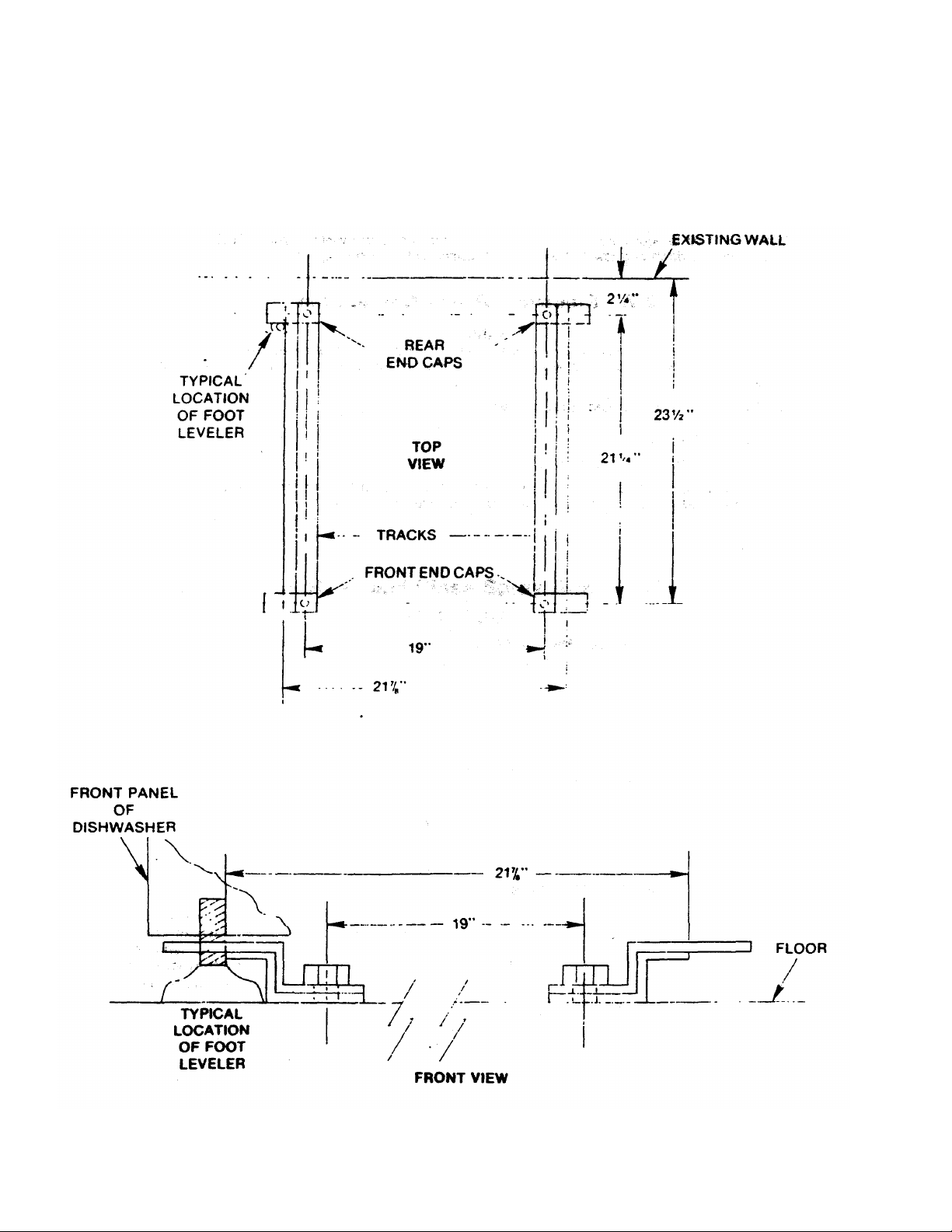
CHAPTER 2 — INSTALLATION INSTRUCTIONS
2-4. Deck Mounting of Dishwashing Machine
The dishwashing machine must be secured in place using the deck mounting tracks and caps
provided with machine.
REFER TO FIGURE 1
1. Install the (4) adjustable feet provided into screw holes where shipping bolts were removed earlier.
2. Adjust the level of the dishwashing machine by screwing the adjustable feet in or out. The front of
the machine should be adjusted 1/4 to 1/2" higher than the back.
3. Install the deck mounting hardware as shown in FIGURE 1 to the deck at location where
dishwashing machine will be permanently positioned. Install 3/8 stainless steel lug bolts to secure
tracks and caps to deck.
4. Drill holes into deck as shown in FIGURE 1 and insure rear holes are located 2 1/4" from wall.
5. The tracks and the rear end caps may be tightened at this time.
6. Slide dishwashing machine onto tracks and into position at rear end caps.
7. Install front end caps into place and adjust if necessary to remove any movement of machine; if
possible, tack weld tracks to deck.
2-5. Gravity Drain System
The drain from the dishwashing machine is a gravity drain system and should have the proper drop
from the machine to floor drain system.
REFER TO FIGURE 2
1. Install hose to drain tube located at left rear of machine as shown in FIGURE 2. Drain tube is 1 1/2'
in diameter and 7" from floor.
2-3
CHAPTER
2 -
INSTALLATION INSTRUCTIONS
FIGURE 2-1
INSTALLATION OF DECK HARDWARE TO SECURE DISHWASHING MACHINE
Not To Scale
2-4

CHAPTER 2 — INSTALLATION INSTRUCTIONS
2-6. Steam Equalizing Vent
The steam equalizing vent is located on the back upper left corner of the dishwashing machine. The vent should
not be blocked or prevented from venting steam off from inside of unit. Undercounter machines are not excluded
from this requirement.
REFER TO FIGURE 2-2
1. Install 1 1/4" pipe to equalizing vent fitting and connect to appropriate venting system. NOTE: Do not pipe steam
line downward toward floor; this will restrict venting of steam.
2-7. Electrical Power Connection
All field wiring connections must conform to the Local and National electrical codes. Install proper circuit breaker,
wire and conduit size. Make sure all electrical connections agree with voltage listed on equipme nt.
MACHINE DATA PLATE is located at top of inner door.
REFER TO FIGURE 2-2
1. Remove control box side panel and lay aside.
2. Make electrical connection through conduit hole provided at rear of box and connect 440 VOLT, 60 HZ, 3
PHASE service to terminal block marked L1, L2 and L3.
WARNING
2-5
 Loading...