


Installaon
Operaon
and
Maintenance
Instrucons
Built-In
Refrigerator/Freezer

TABLE OF CONTENTS
Secon Page
UNPACKING THE UNIT 1
PRE-INSTALLATION 2
INSTALLATION 3
CORNER INSTALLATION AND INSTALLING TWO UNITS SIDE BY SIDE 4
LEVELING THE UNIT 5
INSTALLING THE CABINET 6
INSTALLING THE MODULE 7
INSTALLING THE ICE MAKER 8
ALTITUDE ADJUSTMENT FOR TEMPERATURE CONTROL 8
INSTALLING THE GRILLE ASSEMBLY 9
HINGE AND GASKET ADJUSTMENT AND FACE MOUNTED DOOR HANDLES 10
INSTALLING THE SIDE PANELS AND KICK PLATE 11
CUSTOM DOOR PANELS AND SPECIFICATIONS 12
CUSTOM GRILLE PANELS AND SPECIFICATIONS 13
TRIMLESS OVERLAY DOOR PANELS AND SPECIFICATIONS 14
TRIMLESS OVERLAY GRILLE PANELS AND SPECIFICATIONS 15
EXTENDED PANELS AND SPECIFICATIONS 16/17
EXTENDED GRILLE PANELS AND SPECIFICATIONS 18/19
GLASS PANEL READY WOOD FRAME DOOR SPECIFICATIONS 20/21
INSTALLING A DOOR FRAME TO THE GLASS DOOR 22
INSTALLATION CHECKS/COMMON ERRORS/TROUBLESHOOTING 23
TROUBLESHOOTING 24
USE AND CARE GUIDE 25/27
WARRANTY 28
Before you begin - Read these instrucons completely and carefully.
IMPORTANT - Save these instrucons for local inspector’s use.
IMPORTANT - OBSERVE ALL GOVERNING CODES AND ORDINANCES.
Note to Installer - Be sure to leave these instrucons with the consumer.
Note to Consumer - Keep these instrucons for future reference.

UNPACKING THE UNIT
Remove Packaging
Your refrigerator/freezer has been packed for shipment
with all parts that could be damaged by movement securely fastened. Before using, be sure all packing materials
and tape have been removed.
Important
Keep your carton packaging unl your refrigerator/freezer
has been thoroughly inspected and found to be in good
condion. If there is damage, the packaging will be
needed as proof of damage in transit.
Note to Customer
This merchandise was carefully packed and thoroughly
inspected before leaving our plant. Responsibility for its
safe delivery was assumed by the retailer upon acceptance
of the shipment. Claims for loss or damage sustained in
transit must be made on the retailer as follows:
• Exterior and Concealed Damage
Any damage must be reported immediately to your retailer.
DO NOT RETURN DAMAGED MERCHANDISE TO THE
MANUFACTURER - FILE THE CLAIM WITH THE RETAILER.
Safety
Protect your kitchen oor. Remove all packing materials from cabinet and if there was no freight damage then
destroy cartoning, plasc bags and any exterior wrapping
material. Children should never use these items for play.
Remove all staples from your carton. Staples can cause severe cuts and destroy nishes if they come in contact with
other appliances or furniture. Carefully read and follow
the child safety precauons in the pamphlet enclosed with
your new refrigerator. It is published by the Associaon of
Home Appliance Manufacturers.
Tools to Have Available for Installaon
• Phillips Screwdriver
• Flat Blade Screwdriver
• 5/16 inch & 1/4 inch Hex head Nut driver
• Level
• Drill and Drill Bit (#6 - .204)
• 7/16 inch & 1/2 inch Open End Wrench
• Pliers
• Adjustable Wrench
• 1/4 inch Open End Wrench
• Tape Measure
1
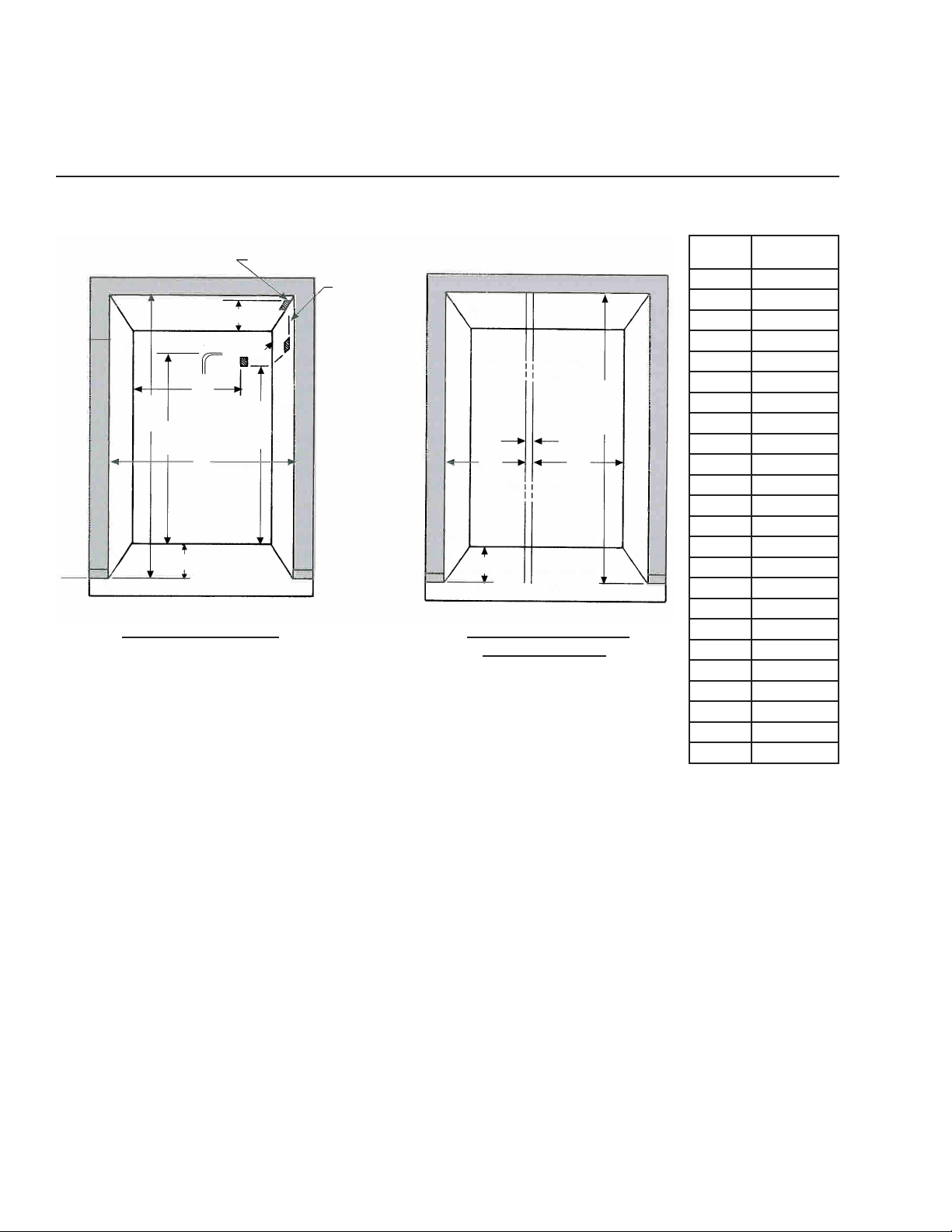
PRE-INSTALLATION
Receptacle must be placed in
this locaon for 18” models.
22”
Ice Maker
Tubing
20”
to
approx.
78”
Min. (typ)
*See note below.
78 1/2”
Min.
(typ)
83 3/4”
84 1/2”
A
24”
Cut-Out Detail for 1 Unit
Cut-Out Width = “A”
22”
83 3/4”
to
84 1/2”
1/2”
A A
24”
*Cut-Out Detail for 2 Units
Placed Side by Side
Cut-Out Width = “A” + “A” + 1/2”
Model
18AR 17 1/2
18AF 17 1/2
18TF 17 1/2
18WC 17 1/2
24AR 23 1/2
24AF 23 1/2
24TF 23 1/2
24WC 23 1/2
24BC 23 1/2
242Z 23 1/2
30AR 29 1/2
30AF 29 1/2
30TF 29 1/2
36AR 35 1/2
36AF 35 1/2
36TF 35 1/2
36SS 35 1/2
363D 35 1/2
42SS 41 1/2
48SS 47 1/2
54SS 53 1/2
60SS 59 1/2
66SS 65 1/2
72SS 71 1/2
Cut-Out Width
(inches)
Floor under product MUST be at or above the same level as the surrounding FINISHED oor, for ease of installaon and
removal.
Electrical: Provide 115 Volt, 60 Cycle, Single Phase, 15 Amp, AC Receptacle. It is recommended that a separate circuit, serving only this appliance, be provided. *Two (2) units side-by-side require separate circuits, except the 60SS and 72SS (see
Instrucon Sheet 34361-000). Electrical opening should be placed 78 1/2 inches minimum from the oor.
Plumbing: Ice maker water supply line (1/4 inch OD copper tubing) to come up the rear of cut-out opening approximately
78 inches o the oor depending on height adjustment. Tubing should then pass around the right side of the module and
around the front to the solenoid valve (see Installaon Instrucons provided with the unit).
NOTE: Allow for three (3) inch high removable ller panel for easy removal of power module.
2

INSTALLATION
Select Locaon
Locate the refrigerator/freezer in the coolest part of the
room, out of direct sunlight and away from heang ducts
or registers.
Do not place the refrigerator/freezer next to heat-producing appliances such as a range, oven or dishwasher. If this
is not possible, a secon of cabinetry or an added layer
of insulaon between the two (2) appliances will help the
refrigerator/freezer operate more eciently.
IMPORTANT
When installing the water line for the ice maker, be sure to
install a SHUT-OFF VALVE at a convenient locaon between
the refrigerator and the supply line.
Required water pressure range is 20 to 120 psi.
Also required is an in-line WATER FILTER between the
refrigerator and the supply line to prevent sediment from
blocking water ow through the water solenoid valve.
NOTE: Self-piercing water valves and plasc tubing are
NOT approved for water supply to ice maker.
Electrical Connecon
The module comes with a 3-prong power supply cord. It
must be plugged into a mang 115 volt, 60 Hz, 15 amp
separately fused, 3-prong grounded outlet serving only
this product, and wired in accordance with Naonal and
Local Electrical Codes and ordinances. A me delay fuse or
circuit breaker is recommended. DO NOT USE AN EXTENSION CORD OR ADAPTER PLUG.
DO NOT REMOVE THE GROUND PRONG FROM THE
POWER SUPPLY CORD UNDER ANY CIRCUMSTANCES!
If voltage varies by 10 percent or more, performance of
your refrigerator/freezer may be aected. Operang the
refrigerator/freezer with insucient voltage can damage
the compressor. Such damage is not covered under your
warranty. If you suspect your voltage is high or low, consult your power company for tesng.
Do NOT pinch, knot, or bend the power cord in any manner.
NEVER unplug the refrigerator/freezer by pulling on the
power cord. Always grip the plug rmly and pull straight
out from the receptacle. To avoid electrical shock, unplug
the refrigerator/freezer before cleaning and before replacing a light bulb.
NOTE: Turning the control to “OFF” turns o the compressor, but does not disconnect power to the light bulb or
other electrical components. The unit MUST be unplugged
or turned o at the circuit breaker.
3
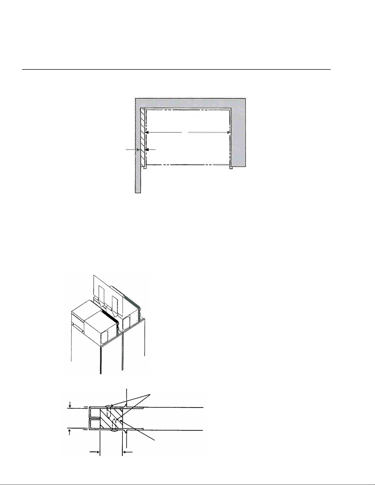
CORNER INSTALLATION AND INSTALLING TWO UNITS SIDE-BY-SIDE
A
1” or
3” Min.
Filler
Enclosure must permit refrigerator to be removed for
service.
PANEL READY UNITS: For corner installaons, a minimum one (1) inch ller must be used as shown above.
Cabinet Outline
7/8”
ANY UNIT WITH FACE MOUNTED HANDLE: Filler must
be three (3) inches minimum.
Installing Two Units Side-By-Side
When two (2) units are installed together, a 23 1/2 inch
x 12 inch (minimum) divider panel needs to be installed
between the two (2) modules (refer to Illustraon) with
self-tapping screws. The divider panel can be made of any
material available, (i.e. 1/32 inch aluminum, 1/8 - 1/4 inch
wood paneling), or you can order Kit # 34747-000 from
the AGA MARVEL Service Department. Locate the divider
panel approximately one (1) inch down from the top of the
cabinet and ush with the back of the cabinet. Drill three
(3) pilot holes approximately 1/2 inch up from the boom
of divider panel, through panel, and into cabinet. Secure
the panel to the cabinet with three (3) screws using pilot
holes previously drilled.
Drill three (3) holes each side equal
distance apart in vercal secon of
aluminum frame and install screws
as shown.
Wood Shim
7/8” x 1” x 68”
1”
• Install wood shim to one of the
cabinets before installing cut-out
cavity (not provided).
• Aer properly installing both
cabinets, drill trim and install pan
head screws (provided).
4
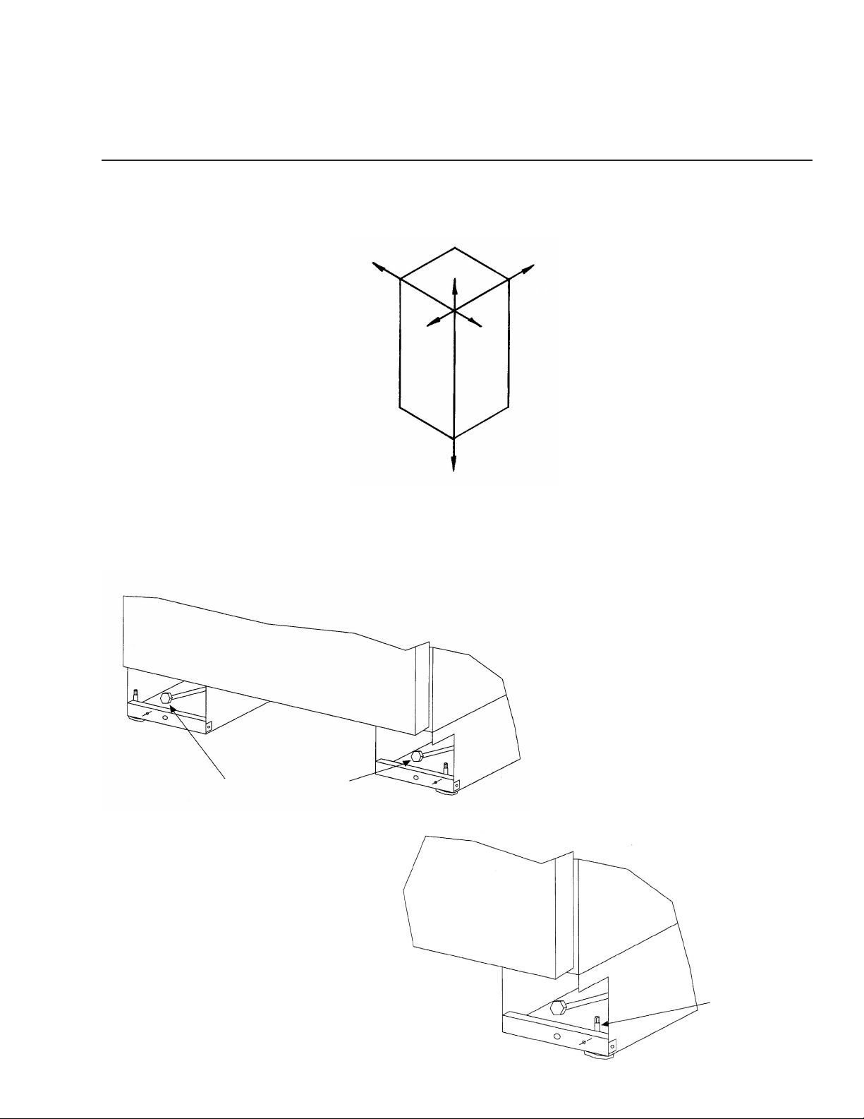
LEVELING THE UNIT
NOTE: Unit MUST be installed level in all planes, on a oor that is strong enough to support a fully loaded
refrigerator/freezer.
This unit is equipped with front and rear rollers. Rollers will aid during installaon. Rear rollers are adjustable from the
front of the unit. Total adjustment is + 5/16, - 5/16. Turn adjusng bolt clockwise to raise cabinet and counterclockwise to
lower cabinet. Front leveling legs must be adjusted to the oor for leveling and to prevent the unit from rolling during use.
Rear Roller Adjustment Bolt
Front leveling leg.
Use 1/4” wrench
to adjust height of
leveling legs.
5
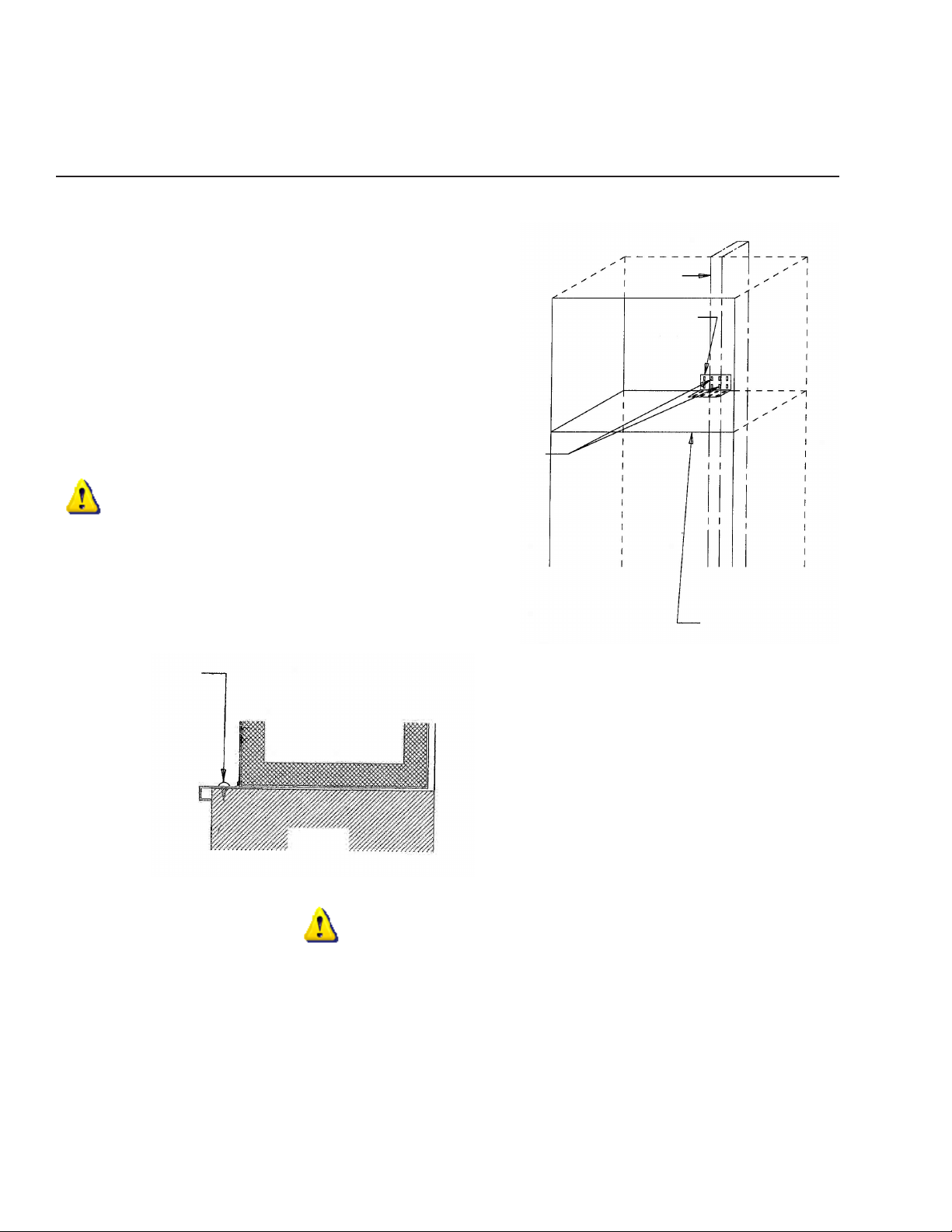
INSTALLING THE CABINET
Before placing the cabinet in opening, the depth of the
cut-out opening should be at least 24 inches. If the cut-out
opening depth is more than 24 inches, then a piece of
wood must be secured crosswise on the wall into the studs
at the height of the an-p bracket. Slide the cabinet into
posion and level the cabinet with adjustable rear roller
and front leveling legs. Locate and mark a center stud in
the back of the cut-out opening for the L-shaped an-p
bracket- (the bracket should t ght to the top of the cabinet). Install at least two screws through the bracket into
the stud located in the wall behind the cabinet. The front
leveling legs also prevent the unit from rolling during use.
Check t of toe kick and grille.
IMPORTANT
Drill and screw through the side trim into adjoining cabinets and/or walls for addional support.
Stud
An-Tip
Bracket
Install at least
two (2) screws
into studs.
Drill three (3) holes equal
distance apart in vercal
secon of aluminum
frame and install pan head
screws as shown.
Refrigerator
Cabinet
Do NOT install an-p bracket over the top of
the power module.
NOTE: 18 and 24 inch wide models have a full
an-p bracket across the back of the units.
The an-p bracket should be aached to the
Finished
Wall or
Cabinets
wall.
IMPORTANT
Recheck cabinet installaon for:
• Proper space le for grille installaon.
• Cabinet levelness.
• Door opening and closing appearance.
• SAFETY...To prevent unit from pping forward:
-Are screws installed securely through front trim
into adjoining cabinetry and/or walls?
-Is an-p mounng bracket secured to wall studs?
Cabinet Top
Aer above checks have been made, proceed with refrigeraon installaon.
6
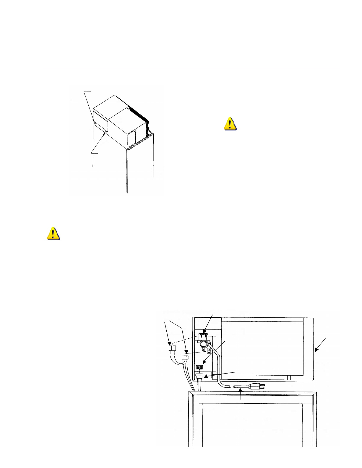
INSTALLING THE MODULE
Rear Shoulder Screw
CAUTION
Module NOT fastened to cabinet below. Remove before
Front
Shoulder
Screw
Place module on top of the cabinet with rear shoulder screws resng on the locator brackets behind the front slots. Slide
module toward the rear of the cabinet unl the rear shoulder screws engage the slots in the rear of the brackets. Rest the
front shoulder screws into the front slots of the brackets.
pping or transporng.
IMPORTANT
Check to make sure wiring and ice maker tubing is clear and not interfering with module seal. Do NOT start product during
construcon, as dust can block module condenser coils. If dust accumulates on coils, vacuum immediately, using a so
brush aachment.
Do NOT operate the refrigerator in the presence of explosive fumes.
Do NOT install the refrigerator where the temperature will drop below 60 degrees F (15 degrees C) or rise above 110 degrees F (43 degrees C). The compressor will NOT be able to maintain proper temperatures.
Ice Maker
Water Valve
Leads
Module
Juncon
Box
Make electrical connecons from the top
of the lower cabinet to the juncon box at
le side of module. If NO ice maker then
Cabinet
Leads
only one cabinet line will be protruding.
With ice maker, be sure to plug the ice
maker line into the module, and the solenoid valve as well. See module diagram on
the right.
Power Cord
7
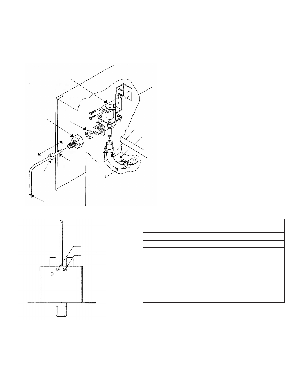
INSTALLING THE ICE MAKER WATER VALVE
Solenoid Wa-
ter Valve
Ice Maker (Solenoid) Connecon
Slip solenoid valve compression nut and
compression sleeve on copper tubing as
shown in diagram. Tighten nut onto water
valve with adjustable wrench. Turn on water
supply valve. Check ngs for leaks. Clamp
ice maker line from cabinet onto solenoid
Garden Hose
Fing
3 1/2”
Gasket
Fill hose to ice maker.
This clamp for tube posioning only.
Check to make sure tube is not collapsed or restricted aer connecng
opposite end to valve.
Sleeve
valve as shown. Tighten clamp securely.
NOTE: If a shuto valve is installed in the
water line do not use a self-piercing type
Compression
Nut
Copper Tubing
(by customer)
Tube Clamp (2)
valve.
ALTITUDE ADJUSTMENT FOR FREEZER/WINE CELLAR TEMPERATURE CONTROL
ALTITUDE CORRECTION
BOTH CUT-IN & CUT-OUT SCREWS MUST BE ADJUSTED.
ALTITUDE IN FEET COUNTERCLOCKWISE TURNS
2,000 7/60 = .12
3,000 13/60 = .22
4,000 19/60 = .32
5,000 25/60 = .42
6,000 31/60 = .52
7,000 37/60 = .62
8,000 43/60 = .72
9,000 49/60 = .82
10,000 55/60 = .92
In
Cut-In Screw
Cut-Out Screw
Out
Colder
1. Turn o power to refrigerator before servicing.
2. Remove screws holding freezer/wine cellar air return and drop air return grille to expose control assembly.
3. Locate cut-in and cut-out adjustment screws.
4. Determine the altude of your locaon and refer to the chart above for the number of counterclockwise turns to adjust
the control for proper calibraon. NOTE: Both cut-in and cut-out screws must be adjusted the same amount. (NEVER
exceed one full turn or damage to the control may occur.)
5. Reassemble the return air grille and plug in the refrigerator.
8

Edge of Cabinet
INSTALLING THE GRILLE ASSEMBLY
GRILLE MOUNTING - STYLE I BRACKET
3.81”
2.00”
.45” typ. (ref.)
Grille Top Trim
See Note #2.
2.06” from inside of
cabinet top trim to
centerline of holes.
Boom of grille
shown behind top
trim. See Note #4.
Cabinet Top Trim
GRILLE MOUNTING - STYLE II
SCREW
Fasten top of grille to enclosure
with screw provided. Cover screw
head with snap-on cap.
Grille Back
Drill four (4) holes 7/64” (.109) dia.
Mounng Brackets
(91180-000) # 8 - 5/8 P.H. Screws
See Note #1.
Instrucons for Installing Grille Brackets
1. Use the two (91180-000) screws to secure each bracket to the cabinet top.
2. Loosen the screws at the top of the mounng bracket. Leave .13 inches (2-3 screw
threads) scking through the bracket.
3. Install the grille by aligning the screws in the top of the bracket with the slots in the grille
top trim.
4. Grille is installed when boom of the grille ts behind the cabinet trim across the front.
5. Pull grille forward about an inch at the top and reghten the screws in the top of the
bracket.
GRILLE MOUNTING - STYLE III SPRING
Module
Spring
(81050-000)
24”, 30” & 36” wide units will use
one (1) spring (81050-000) and one
(1) L-bracket (30483-000) to secure
the facia.
L-Bracket
(30483-000)
Screw A
An-Tip
Bracket
Facia Bracket
Facia
Kappet Screw
(into enclosure)
Screw Cap
Instrucons for Installing Grille Mounng (STYLE III) Spring
1. Remove screw A in mounng bracket. Mount L-bracket with screw A.
2. Hook one end of spring (81050-000) through hole in L-bracket. Holding the facia in posion - stretch the
spring and secure the hook end to the facia through a square top hole in the facia.
42” & 48” wide units will
use two (2) springs (81050-
000) and two (2) L-brackets
(30483-000) to secure the
facia.
9

HINGE AND GASKET ADJUSTMENTS AND FACE MOUNTED DOOR HANDLES
Hinge and Gasket Adjustment
It is possible that doors may become out of adjustment in
shipment. See diagram on right.
Cabinet
If product is installed slightly “out of level”, doors may not
line up properly. Check this BEFORE adjusng hinges.
Adjustable Screws
NOTE: Door gaskets occasionally compress in shipment. If
Edge of Door Trim
gasket does not seal all around, warm slightly with a hair
dryer and pull outward soly unl magnet in gasket seals
against cabinet.
Door
Panel Ready Doors
To expose the concealed door screws, rst remove handle trim. Then slide trim over hinge toward handle side. If your unit
requires door panels, see “Custom Door Panel” secon, on page 14.
All hinge secons aached to doors, adjust le or right. Top and boom cabinet hinges are also adjustable in and out.
Change or Tighten Face Mounted Door Handles
1. Open the door - remove the interior door shelves.
2. Remove the screws that secure the shelf mounng rail
and the rail.
3. Remove the plug buons (exposing handle screws) make sure not to scratch the inner liner.
Stainless Steel Wrap Door Units
To expose concealed door hinge screws, remove plug
buons if present. All hinge secons aached to doors
adjust le or right. Top and boom cabinet hinges are
also adjustable in and out. See diagram (shown without
cabinet trim).
4. Remove the foam insert to expose the door handle
mounng screw.
5. Change handle/ghten screw and replace foam insert,
plug buon, shelf rail and door shelf.
10
Shelf Mounng
Rail and Screw
Foam
Handle Mounng
Screw
Door Shelf
Plug Buon
Foam Insert
Door Handle
Cabinet
Adjustable
Screws
Door

INSTALLING THE SIDE PANELS AND KICK PLATE
Instrucons for Fastening Side Panels to Refrigerator
1. Side panels should be 24 inches D (or 24 5/16
inches D when tucked into the front trim).
2. Panel height to match installaon height.
3. Install the side panels per drawings on the
right.
NOTE: To avoid damage to panels or ooring,
raise panels slightly, to clear oor when installing.
Drill three (3) holes equal distance apart in vercal secon of aluminum frame and install pan
head screws as shown.
Anchor side panel with screw as shown. Be sure
screw used goes no more than 1/2 inch deep into
product. Do NOT overghten.
“A”
“B”
“C”
“D”
Typ.
1 1/8”
3/16” Thick Back Up
1/8” Thick Back Up
2 3/16”
Typical Side Panel Installaons
1/4” Thick Baens
1/4” Plywood/Panel
3/16” Thick Baens
1/4” Plywood/Panel
24 5/16”
1/16” Rout
1/2” Plywood/Panel
11/32”
Metal Side Panel
24”
(Typ. Installaon Opening)
5/16”
Drill three (3) holes equal distance apart in vercal secon of aluminum frame and install # 6 - 3/8 pan head screws as
shown (provided).
Aach side panel to cabinet with screws as shown. Screws must not penetrate cabinet more than 1/2 inch.
Kick Plate Installaon
Use two (2) #8 sheet metal screws to facilitate holding your kick plate in place. Mount screws in holes in roller base. Notching of upper corners may be required to clear hinges.
Measure the distance between
mounng holes on roller base.
#8 Sheet
Metal Screw
11

CUSTOM DOOR PANELS AND SPECIFICATIONS
The AGA MARVEL Panel Ready Built-In design allows you to insert decorave material on the doors of your refrigerator/
freezer. If a panel thinner than 1/4 inch is being used, we recommend a ller be inserted behind it for a proper t, as frames
are designed to accept up to a 1/4 inch of material. If a raised panel is used, route edges to t the frame.
CAUTION
Door panels MUST NOT exceed 50 lbs. Do NOT use glass, mirrors, granite or similar heavy materials for panels. Panels
weighing more than 50 lbs. may cause product damage. We recommend that the door load (panel and food) NOT exceed 90
lbs.
For models:
All Refrigerator (AR), All Freezer (AF), Top Freezer (TF), Side-by-Side (SS), and Side-by-Side 3 Door (3D)
Model AR H W
18AR Custom Panel 68” 15 1/2”
24AR Custom Panel 68” 21 1/2”
30AR Custom Panel 68” 27 1/2”
36AR Custom Panel 68” 33 1/2”
Model AF H W
18AF Custom Panel 68” 15 1/2”
24AF Custom Panel 68” 21 1/2”
30AF Custom Panel 68” 27 1/2”
36AF Custom Panel 68” 33 1/2”
Model TF
18TF Custom Panel 22 1/4” 15 1/2” 45 1/8” 15 1/2”
24TF Custom Panel 22 1/4” 21 1/2” 45 1/8” 21 1/2”
30TF Custom Panel 22 1/4” 27 1/2” 45 1/8” 27 1/2”
36TF Custom Panel 22 1/4” 33 1/2” 45 1/8” 33 1/2”
Model SS
36SS Custom Panel 68” 15 1/2” 68” 17”
42SS Custom Panel 68” 17” 68” 21 1/2”
48SS Custom Panel 68” 17” 68” 27 1/2”
60SS Custom Panel 68” 21 1/2” 68” 33 1/2”
72SS Custom Panel 68” 33 1/2” 68” 33 1/2”
Model 3D
363D Custom Panel 22 1/4” 15 1/2” 68” 17” 45 1/8” 15 1/2”
Freezer Door Refrigerator Door
H W H W
Freezer Door Refrigerator Door
H W H W
Freezer Door Refrigerator Door Refrigerator Door 2
H W H W H W
W
3/8”
H
Min.
1/4”
Max.
Removing Protecve Film from Factory Installed Decorave Panels
• Cabinets are shipped with protecve lm over the exterior surface of
decorave panels (oponal).
• Do NOT remove protecve lm unl the cabinet has been completely
installed to prevent scratching or marring the decorave panels.
• To remove the protecve lm, rmly grasp the loose edge of the lm and
slowly pull the lm downward o the decorave panels.
• Decorave panels may be removed if necessary by removing the handle
screws and handle and then sliding the decorave panel out of the frame.
12
Screw
Screw
Cap
Handle

CUSTOM GRILLE PANELS AND SPECIFICATIONS
Custom Grille Panels
• Remove screws and handle.
• Slide custom panel into posion in door trim opening.
• Do ALL doors.
CAUTION
Grille panels MUST NOT exceed 20 lbs. Panels weighing
more than 20 lbs. may cause product damage.
• Do NOT replace handle unl hinge and gasket adjustments have been made. See page 12.
• Replace handle and screws and install plasc screw
caps provided.
For grille installaon refer to page 11, Grille Assembly Installaon, and see separate Instrucon Sheet, No. 31395-
000.
For models:
All Refrigerator (AR), All Freezer (AF), Top Freezer (TF), Side-by-Side (SS), and Side-by-Side 3 Door (3D)
Model AR H W
18AR Grille Panel 8 9/16” 14 13/16”
24AR Grille Panel 8 9/16” 20 13/16”
W
30AR Grille Panel 8 9/16” 26 13/16”
36AR Grille Panel 8 9/16” 32 13/16”
Model AF H W
H
3/8”
Min.
18AF Grille Panel 8 9/16” 14 13/16”
24AF Grille Panel 8 9/16” 20 13/16”
30AF Grille Panel 8 9/16” 26 13/16”
36AF Grille Panel 8 9/16” 32 13/16”
Model TF H W
18TF Grille Panel 8 9/16” 14 13/16”
24TF Grille Panel 8 9/16” 20 13/16”
30TF Grille Panel 8 9/16” 26 13/16”
36TF Grille Panel 8 9/16” 32 13/16”
Model SS H W
36SS Grille Panel 8 9/16” 32 13/16”
42SS Grille Panel 8 9/16” 38 13/16”
48SS Grille Panel 8 9/16” 44 13/16”
54SS Grille Panel 8 9/16” 50 13/16”
60SS Grille Panel 8 9/16” 56 13/16”
66SS Grille Panel 8 9/16” 62 13/16”
72SS Grille Panel 8 9/16” 68 13/16”
Model 3D H W
363D Grille Panel 8 9/16” 32 13/16”
NOTE: All center hinged doors CANNOT exceed 1/2 inch in
panel thickness from the door trim face.
1/4” Max.
Note: 1/2” Min. (Relief)
13

TRIMLESS OVERLAY DOOR PANELS AND SPECIFICATIONS
For models:
All Refrigerator (AR), All Freezer (AF), Top Freezer (TF), Side-by-Side (SS), and Side-by-Side 3 Door (3D)
Model 18AR & 18AF H W
Refrigerator or Freezer Overlay Panel 68 1/4” 15 3/4”
Refrigerator or Freezer Spacer Panel 66 3/4” 14 1/4”
Refrigerator or Freezer Backer Panel 68” 15 1/2”
Model 24AR & 24AF H W
Refrigerator or Freezer Overlay Panel 68 1/4” 21 3/4”
Refrigerator or Freezer Spacer Panel 66 3/4” 20 1/4”
Refrigerator or Freezer Backer Panel 68” 21 1/2”
Model 30AR & 30AF H W
Refrigerator or Freezer Overlay Panel 68 1/4” 27 3/4”
Refrigerator or Freezer Spacer Panel 66 3/4” 26 1/4”
Refrigerator or Freezer Backer Panel 68” 27 1/2”
Model 36AR & 36AF H W
Refrigerator or Freezer Overlay Panel 68 1/4” 33 3/4”
Refrigerator or Freezer Spacer Panel 66 3/4” 32 1/4”
Refrigerator or Freezer Backer Panel 68” 33 1/2”
Model 18TF H W
Refrigerator Overlay Panel 45 3/8” 15 3/4”
Refrigerator Spacer Panel 43 7/8” 14 1/4”
Refrigerator Backer Panel 45 1/8” 15 1/2”
H W
Freezer Overlay Panel 22 1/2” 15 3/4”
Freezer Spacer Panel 21” 14 1/4”
Freezer Backer Panel 22 1/4” 15 1/2”
Model 24TF H W
Refrigerator Overlay Panel 45 3/8” 21 3/4”
Refrigerator Spacer Panel 43 7/8” 20 1/4”
Refrigerator Backer Panel 45 1/8” 21 1/2”
H W
Freezer Overlay Panel 22 1/2” 21 3/4”
Freezer Spacer Panel 21” 20 1/4”
Freezer Backer Panel 22 1/4” 21 1/2”
Model 30TF H W
Refrigerator Overlay Panel 45 3/8” 27 3/4”
Refrigerator Spacer Panel 43 7/8” 26 1/4”
Refrigerator Backer Panel 45 1/8” 27 1/2”
H W
Freezer Overlay Panel 22 1/2” 27 3/4”
Freezer Spacer Panel 21” 26 1/4”
Freezer Backer Panel 22 1/4” 27 1/2”
Model 36TF H W
Refrigerator Overlay Panel 45 3/8” 33 3/4”
Refrigerator Spacer Panel 43 7/8” 32 1/4”
Refrigerator Backer Panel 45 1/8” 33 1/2”
H W
Freezer Overlay Panel 22 1/2” 33 3/4”
Freezer Spacer Panel 21” 32 1/4”
Freezer Backer Panel 22 1/4” 33 1/2”
Model 36SS H W
Refrigerator Overlay Panel 68 1/4” 17 1/4”
Refrigerator Spacer Panel 66 3/4” 15 3/4”
Refrigerator Backer Panel 68” 17”
H W
Freezer Overlay Panel 68 1/4” 15 3/4”
Freezer Spacer Panel 66 3/4” 14 1/4”
Freezer Backer Panel 68” 15 1/2”
Model 42SS H W
Refrigerator Overlay Panel 68 1/4” 21 3/4”
Refrigerator Spacer Panel 66 3/4” 20 1/4”
Refrigerator Backer Panel 68” 21 1/2”
H W
Freezer Overlay Panel 68 1/4” 17 1/4”
Freezer Spacer Panel 66 3/4” 15 3/4”
Freezer Backer Panel 68” 17”
Model 48SS H W
Refrigerator Overlay Panel 68 1/4” 27 3/4”
Refrigerator Spacer Panel 66 3/4” 26 1/4”
Refrigerator Backer Panel 68” 27 1/2”
H W
Freezer Overlay Panel 68 1/4” 17 1/4”
Freezer Spacer Panel 66 3/4” 15 3/4”
Freezer Backer Panel 68” 17”
Model 60SS H W
Refrigerator Overlay Panel 68 1/4” 33 3/4”
Refrigerator Spacer Panel 66 3/4” 32 1/4”
Refrigerator Backer Panel 68” 33 1/2”
Freezer Overlay Panel 68 1/4” 21 3/4”
Freezer Spacer Panel 66 3/4” 20 1/4”
Freezer Backer Panel 68” 21 1/2”
Model 72SS H W
Refrigerator Overlay Panel 68 1/4” 33 3/4”
Refrigerator Spacer Panel 66 3/4” 32 1/4”
Refrigerator Backer Panel 68” 33 1/2”
Freezer Overlay Panel 68 1/4” 33 3/4”
Freezer Spacer Panel 66 3/4” 32 1/4”
Freezer Backer Panel 68” 33 1/2”
Model 363D H W
Refrigerator 1 Overlay Panel 68 1/4” 17 1/4”
Refrigerator 1 Spacer Panel 66 3/4” 15 3/4”
Refrigerator 1 Backer Panel 68” 17”
Refrigerator 2 Overlay Panel 45 3/8” 15 3/4”
Refrigerator 2 Spacer Panel 43 7/8” 14 1/4”
Refrigerator 2 Backer Panel 45 1/8” 15 1/2”
Freezer Overlay Panel 22 1/2” 15 3/4”
Freezer Spacer Panel 21” 14 1/4”
Freezer Backer Panel 22 1/4” 15 1/2”
3/32”
Custom
Door
Panel
Front
H W
H W
H W
H W
Slot - panel ts in.
3/32” 5/8”
14
1/8”
Min.
1/4”
Max.
Typical Door Assembly with “Trimless” Panel
Door
Typical
All
Around
Panel

TRIMLESS OVERLAY GRILLE PANELS AND SPECIFICATIONS
For models:
All Refrigerator (AR), All Freezer (AF), Top Freezer (TF), Side-by-Side (SS), and Side-by-Side 3 Door (3D)
Model 18AR & 18AF H W
Refrigerator or Freezer Grille Overlay Panel 8 7/8” 15 1/8”
Refrigerator or Freezer Grille Spacer Panel 7 5/16” 13 9/16”
Refrigerator or Freezer Grille Backer Panel 8 9/16” 14 13/16”
Model 24AR & 24AF H W
Refrigerator or Freezer Grille Overlay Panel 8 7/8” 21 1/8”
Refrigerator or Freezer Grille Spacer Panel 7 5/16” 19 9/16”
Refrigerator or Freezer Grille Backer Panel 8 9/16” 20 13/16”
Model 30AR & 30AF H W
Refrigerator or Freezer Grille Overlay Panel 8 7/8” 27 1/8”
Refrigerator or Freezer Grille Spacer Panel 7 5/16” 25 9/16”
Refrigerator or Freezer Grille Backer Panel 8 9/16” 26 13/16”
Model 36AR & 36AF H W
Refrigerator or Freezer Grille Overlay Panel 8 7/8” 33 1/8”
Refrigerator or Freezer Grille Spacer Panel 7 5/16” 31 9/16”
Refrigerator or Freezer Grille Backer Panel 8 9/16” 32 13/16”
Model 18TF H W
Top Freezer Grille Overlay Panel 8 7/8” 15 1/8”
Top Freezer Grille Spacer Panel 7 5/16” 13 9/16”
Top Freezer Grille Backer Panel 8 9/16” 14 13/16”
Model 24TF H W
Top Freezer Grille Overlay Panel 8 7/8” 21 1/8”
Top Freezer Grille Spacer Panel 7 5/16” 19 9/16”
Top Freezer Grille Backer Panel 8 9/16” 20 13/16”
Model 30TF H W
Top Freezer Grille Overlay Panel 8 7/8” 27 1/8”
Top Freezer Grille Spacer Panel 7 5/16” 25 9/16”
Top Freezer Grille Backer Panel 8 9/16” 26 13/16”
Model 36TF H W
Top Freezer Grille Overlay Panel 8 7/8” 33 1/8”
Top Freezer Grille Spacer Panel 7 5/16” 31 9/16”
Top Freezer Grille Backer Panel 8 9/16” 32 13/16”
Model 36SS H W
Side-by-Side Grille Overlay Panel 8 7/8” 33 1/8”
Side-by-Side Grille Spacer Panel 7 5/16” 31 9/16”
Side-by-Side Grille Backer Panel 8 9/16” 32 13/16”
Model 363D H W
Three Door Grille Overlay Panel 8 7/8” 33 1/8”
Three Door Grille Spacer Panel 7 5/16” 31 9/16”
Three Door Grille Backer Panel 8 9/16” 32 13/16”
Model 42SS H W
Side-by-Side Grille Overlay Panel 8 7/8” 39 1/8”
Side-by-Side Grille Spacer Panel 7 5/16” 37 9/16”
Side-by-Side Grille Backer Panel 8 9/16” 38 13/16”
H
Model 48SS H W
Side-by-Side Grille Overlay Panel 8 7/8” 45 1/8”
Side-by-Side Grille Spacer Panel 7 5/16” 43 9/16”
Side-by-Side Grille Backer Panel 8 9/16” 44 13/16”
Model 54SS H W
Side-by-Side Grille Overlay Panel 8 7/8” 51 1/8”
Side-by-Side Grille Spacer Panel 7 5/16” 49 9/16”
Side-by-Side Grille Backer Panel 8 9/16” 50 13/16”
Model 60SS H W
Side-by-Side Grille Overlay Panel 8 7/8” 57 1/8”
Side-by-Side Grille Spacer Panel 7 5/16” 55 9/16”
Side-by-Side Grille Backer Panel 8 9/16” 56 13/16”
Model 66SS H W
Side-by-Side Grille Overlay Panel 8 7/8” 63 1/8”
Side-by-Side Grille Spacer Panel 7 5/16” 61 9/16”
Side-by-Side Grille Backer Panel 8 9/16” 62 13/16”
Model 72SS H W
Side-by-Side Grille Overlay Panel 8 7/8” 69 1/8”
Side-by-Side Grille Spacer Panel 7 5/16” 67 9/16”
Side-by-Side Grille Backer Panel 8 9/16” 68 13/16”
1/8”
Min.
Custom
Grille
Panel
Front
W
Typical Grille Assembly with “Trimless” Panel
3/32” 3/32” 5/8”
Grille Frame
1/4”
Max.
Typical All
Around Panel
15

EXTENDED PANELS AND SPECIFICATIONS
Finish this area of panel
1-5/16
Secon C-C
1/4 Max.
3/32
11/16
Finished Side of Door
1/8 Min.
Handle Side
A
H
1/8 Min.
3/32
1/4 Max.
1/8
3/4
A
Secon A-A
Finished Side of Door
Top of Door
5/8
1/4 Max.
Custom Door
Panel Dimensions
C
C
Finished Side of Door
3/32
1/8 Min.
Secon B-B
Hinge Side
B
Finished
B
Side of Door
D
D
Secon D-D
Boom of Door
W
Finished Side of Door
1/8 Min.
3/4
1/8
3/32
16
1/4 Max.

EXTENDED PANELS AND SPECIFICATIONS
For models:
All Refrigerator (AR), All Freezer (AF), Top Freezer (TF), Side-by-Side (SS), and Side-by-Side 3 Door (3D)
Model 18AR & 18AF H W
Refrigerator or Freezer Overlay Panel 68 1/4” 16 3/16”
Refrigerator or Freezer Spacer Panel 66 3/4” 14 1/4”
Refrigerator or Freezer Backer Panel 68” 15 1/2”
Model 24AR & 24AF H W
Refrigerator or Freezer Overlay Panel 68 1/4” 22 3/16”
Refrigerator or Freezer Spacer Panel 66 3/4” 20 1/4”
Refrigerator or Freezer Backer Panel 68” 21 1/2”
Model 30AR & 30AF H W
Refrigerator or Freezer Overlay Panel 68 1/4” 28 3/16”
Refrigerator or Freezer Spacer Panel 66 3/4” 26 1/4”
Refrigerator or Freezer Backer Panel 68” 27 1/2”
Model 36AR & 36AF H W
Refrigerator or Freezer Overlay Panel 68 1/4” 34 3/16”
Refrigerator or Freezer Spacer Panel 66 3/4” 32 1/4”
Refrigerator or Freezer Backer Panel 68” 33 1/2”
Model 18TF H W
Refrigerator Overlay Panel 45 3/8” 16 3/16”
Refrigerator Spacer Panel 43 7/8” 14 1/4”
Refrigerator Backer Panel 45 1/8” 15 1/2”
H W
Freezer Overlay Panel 22 1/2” 16 3/16”
Freezer Spacer Panel 21” 14 1/4”
Freezer Backer Panel 22 1/4” 15 1/2”
Model 24TF H W
Refrigerator Overlay Panel 45 3/8” 22 3/16”
Refrigerator Spacer Panel 43 7/8” 20 1/4”
Refrigerator Backer Panel 45 1/8” 21 1/2”
H W
Freezer Overlay Panel 22 1/2” 22 3/16”
Freezer Spacer Panel 21” 20 1/4”
Freezer Backer Panel 22 1/4” 21 1/2”
Model 30TF H W
Refrigerator Overlay Panel 45 3/8” 28 3/16”
Refrigerator Spacer Panel 43 7/8” 26 1/4”
Refrigerator Backer Panel 45 1/8” 27 1/2”
H W
Freezer Overlay Panel 22 1/2” 28 3/16”
Freezer Spacer Panel 21” 26 1/4”
Freezer Backer Panel 22 1/4” 27 1/2”
Model 36TF H W
Refrigerator Overlay Panel 45 3/8” 34 3/16”
Refrigerator Spacer Panel 43 7/8” 32 1/4”
Refrigerator Backer Panel 45 1/8” 33 1/2”
H W
Freezer Overlay Panel 22 1/2” 34 3/16”
Freezer Spacer Panel 21” 32 1/4”
Freezer Backer Panel 22 1/4” 33 1/2”
Model 36SS H W
Refrigerator Overlay Panel 68 1/4” 17 11/16”
Refrigerator Spacer Panel 66 3/4” 15 3/4”
Refrigerator Backer Panel 68” 17”
H W
Freezer Overlay Panel 68 1/4” 16 3/16”
Freezer Spacer Panel 66 3/4” 14 1/4”
Freezer Backer Panel 68” 15 1/2”
Model 42SS H W
Refrigerator Overlay Panel 68 1/4” 22 3/16”
Refrigerator Spacer Panel 66 3/4” 20 1/4”
Refrigerator Backer Panel 68” 21 1/2”
H W
Freezer Overlay Panel 68 1/4” 17 11/16”
Freezer Spacer Panel 66 3/4” 15 3/4”
Freezer Backer Panel 68” 17”
Model 48SS H W
Refrigerator Overlay Panel 68 1/4” 28 3/16”
Refrigerator Spacer Panel 66 3/4” 26 1/4”
Refrigerator Backer Panel 68” 27 1/2”
H W
Freezer Overlay Panel 68 1/4” 17 11/16”
Freezer Spacer Panel 66 3/4” 15 3/4”
Freezer Backer Panel 68” 17”
Model 60SS H W
Refrigerator Overlay Panel 68 1/4” 34 3/16”
Refrigerator Spacer Panel 66 3/4” 32 1/4”
Refrigerator Backer Panel 68” 33 1/2”
Freezer Overlay Panel 68 1/4” 22 3/16”
Freezer Spacer Panel 66 3/4” 20 1/4”
Freezer Backer Panel 68” 21 1/2”
Model 72SS H W
Refrigerator Overlay Panel 68 1/4” 34 3/16”
Refrigerator Spacer Panel 66 3/4” 32 1/4”
Refrigerator Backer Panel 68” 33 1/2”
Freezer Overlay Panel 68 1/4” 34 3/16”
Freezer Spacer Panel 66 3/4” 32 1/4”
Freezer Backer Panel 68” 33 1/2”
Model 363D H W
Refrigerator 1 Overlay Panel 68 1/4” 17 11/16”
Refrigerator 1 Spacer Panel 66 3/4” 15 3/4”
Refrigerator 1 Backer Panel 68” 17”
Refrigerator 2 Overlay Panel 45 3/8” 16 3/16”
Refrigerator 2 Spacer Panel 43 7/8” 14 1/4”
Refrigerator 2 Backer Panel 45 1/8” 15 1/2”
Freezer Overlay Panel 22 1/2” 16 3/16”
Freezer Spacer Panel 21” 14 1/4”
Freezer Backer Panel 22 1/4” 15 1/2”
Inside surface to be nished
These two (2)
surfaces are ush.
H W
H W
H W
H W
This door requires a face mounted
door handle
17

EXTENDED GRILLE PANELS AND SPECIFICATIONS
A
H
25/32
Finished Side of Grille
1/4 Maximum
1/8 Minimum
3/32
5/32
Secon A-A
29/32
1-17/32
A
B
W
B
1/4 Maximum
27/32
3/32
Finished Side of Grille
1/8 Minimum
1-15/32
18
1/4 Maximum
3/32
1/8 Minimum
Secon B-B
Typical
Both Sides

EXTENDED GRILLE PANELS AND SPECIFICATIONS
For models:
All Refrigerator (AR), All Freezer (AF), Top Freezer (TF), Side-by-Side (SS), and Side-by-Side 3 Door (3D)
Model 18AR & 18AF H W
Refrigerator or Freezer Grille Overlay Panel 9 5/8” 16 1/2”
Refrigerator or Freezer Grille Spacer Panel 7 5/16” 13 9/16”
Refrigerator or Freezer Grille Backer Panel 8 9/16” 14 13/16”
Model 24AR & 24AF H W
Refrigerator or Freezer Grille Overlay Panel 9 5/8” 22 1/2”
Refrigerator or Freezer Grille Spacer Panel 7 5/16” 19 9/16”
Refrigerator or Freezer Grille Backer Panel 8 9/16” 20 13/16”
Model 30AR & 30AF H W
Refrigerator or Freezer Grille Overlay Panel 9 5/8” 28 1/2”
Refrigerator or Freezer Grille Spacer Panel 7 5/16” 25 9/16”
Refrigerator or Freezer Grille Backer Panel 8 9/16” 26 13/16”
Model 36AR & 36AF H W
Refrigerator or Freezer Grille Overlay Panel 9 5/8” 34 1/2”
Refrigerator or Freezer Grille Spacer Panel 7 5/16” 31 9/16”
Refrigerator or Freezer Grille Backer Panel 8 9/16” 32 13/16”
Model 18TF H W
Top Freezer Grille Overlay Panel 9 5/8” 16 1/2”
Top Freezer Grille Spacer Panel 7 5/16” 13 9/16”
Top Freezer Grille Backer Panel 8 9/16” 14 13/16”
Model 24TF H W
Top Freezer Grille Overlay Panel 9 5/8” 22 1/2”
Top Freezer Grille Spacer Panel 7 5/16” 19 9/16”
Top Freezer Grille Backer Panel 8 9/16” 20 13/16”
Model 30TF H W
Top Freezer Grille Overlay Panel 9 5/8” 28 1/2”
Top Freezer Grille Spacer Panel 7 5/16” 25 9/16”
Top Freezer Grille Backer Panel 8 9/16” 26 13/16”
Model 36TF H W
Top Freezer Grille Overlay Panel 9 5/8” 34 1/2”
Top Freezer Grille Spacer Panel 7 5/16” 31 9/16”
Top Freezer Grille Backer Panel 8 9/16” 32 13/16”
Model 36SS H W
Side-by-Side Grille Overlay Panel 9 5/8” 34 1/2”
Side-by-Side Grille Spacer Panel 7 5/16” 31 9/16”
Side-by-Side Grille Backer Panel 8 9/16” 32 13/16”
Model 363D H W
Three Door Grille Overlay Panel 9 5/8” 34 1/2”
Three Door Grille Spacer Panel 7 5/16” 31 9/16”
Three Door Grille Backer Panel 8 9/16” 32 13/16”
Model 42SS H W
Side-by-Side Grille Overlay Panel 9 5/8” 40 1/2”
Side-by-Side Grille Spacer Panel 7 5/16” 37 9/16”
Side-by-Side Grille Backer Panel 8 9/16” 38 13/16”
Model 48SS H W
Side-by-Side Grille Overlay Panel 9 5/8” 46 1/2”
Side-by-Side Grille Spacer Panel 7 5/16” 43 9/16”
Side-by-Side Grille Backer Panel 8 9/16” 44 13/16”
Model 54SS H W
Side-by-Side Grille Overlay Panel 9 5/8” 52 1/2”
Side-by-Side Grille Spacer Panel 7 5/16” 49 9/16”
Side-by-Side Grille Backer Panel 8 9/16” 50 13/16”
Model 60SS H W
Side-by-Side Grille Overlay Panel 9 5/8” 58 1/2”
Side-by-Side Grille Spacer Panel 7 5/16” 55 9/16”
Side-by-Side Grille Backer Panel 8 9/16” 56 13/16”
Model 66SS H W
Side-by-Side Grille Overlay Panel 9 5/8” 64 1/2”
Side-by-Side Grille Spacer Panel 7 5/16” 61 9/16”
Side-by-Side Grille Backer Panel 8 9/16” 62 13/16”
Model 72SS H W
Side-by-Side Grille Overlay Panel 9 5/8” 70 1/2”
Side-by-Side Grille Spacer Panel 7 5/16” 67 9/16”
Side-by-Side Grille Backer Panel 8 9/16” 68 13/16”
19

GLASS PANEL READY WOOD FRAME DOOR SPECIFICATIONS
Model AR H W
18AR - WGP 68 1/8” 16 1/4” 2 1/2”
18AR - SGP 68 1/8” 16 1/4” 2 1/2”
24AR - WGP 68 1/8” 22 1/4” 2 1/2”
24AR - SGP 68 1/8” 22 1/4” 2 1/2”
30AR - WGP 68 1/8” 28 1/4” 2 1/2”
30AR - SGP 68 1/8” 28 1/4” 2 1/2”
36AR - WGP 68 1/8” 34 1/4” 2 1/2”
36AR - WGP 68 1/8” 34 1/4” 2 1/2”
Model WC H W
18WC - SGP 68 1/8” 16 1/4” 2 1/2”
24WC - SGP 68 1/8” 22 1/4” 2 1/2”
Model 2Z H W
242Z - SGP 68 1/8” 22 1/4” 2 1/2”
Model BC H W
24BC - SGP 68 1/8” 22 1/4” 2 1/2”
Model SS H W
60SS - WGP 68 1/8” 34 1/4” 2 1/2”
60SS - SGP 68 1/8” 34 1/4” 2 1/2”
72SS - WGP 68 1/8” 34 1/4” 2 1/2”
72SS - SGP 68 1/8” 34 1/4” 2 1/2”
Frame with
Min.
Frame with
Min.
Frame with
Min.
Frame with
Min.
Frame with
Min.
20

GLASS PANEL READY WOOD FRAME DOOR SPECIFICATIONS
W
2.50” Typ.
All Around
H
.50”
1.38” Typ.
(2) Plcs.
.33” Typ.
(2) Plcs.
21

INSTALLING A DOOR FRAME TO THE GLASS DOOR
The door frame can be mounted to the glass door with the glass door on or o the unit. The door handle needs to be
mounted to the door frame before the frame is mounted to the glass door.
Glass Door On the Unit
1. Lay the unit on its back.
2. Open the glass door 180 degrees and support the glass door during installaon.
3. Pull the door gasket back along the top and boom of the glass door to expose the mounng holes for the door frame.
There are twelve (12) total mounng holes on the door - four (4) on each side and two (2) on the top and boom of the
door. Screws will be mounted around the outside diameter of the door on the gasket side.
4. Line up the door frame that is to be mounted to the unit and mark the hole locaons on the door frame. Drill 1/8” pilot
holes, 1/4” deep to aid during mounng of the door frame.
5. Recommended screws to use to mount the door frame are 1 1/4” long wood screws.
6. Aer installing the mounng screws, press the door gasket back into the gasket retainer. Make sure the gasket is seated
into the corners to retain proper door gasket seal.
Glass Door O the Unit
1. Remove the four (4) hinge bolts from the door- two (2) at the top and two (2) at the boom of the door. Retain the two
(2) hinge spacers. One (1) at the top and one (1) at the boom of the door.
2. Lay the glass door on a surface that will protect the door frame during assembly of the frame to the glass door.
3. Complete Steps 3 through 6 as listed in the above secon “Glass Door On the Unit”.
4. Mount the door to the unit using the hinge spacers and hinge bolts that were removed when taking the glass door o
the unit.
22
Door Gasket
(shown pulled up)
Screws to mount the door
frame to the glass door.
Door Frame

INSTALLATION CHECKS/COMMON ERRORS
Installaon Checks
• An-p mounng bracket must be installed correctly and anchored to prevent cabinet from pping
forward.
• Module should be engaged in the slots on the module
posioning brackets and seated on the foam seal
without air gaps. Module posioning brackets should
not be removed.
• All wires from the lower cabinet to module must be
securely connected. If a problem is suspected, inspect
both male and female plugs and insure that the terminals in the plug are suciently forward to engage.
• Cabinet must be level both side-to-side and frontto-back. Front leveling legs should rest rmly on the
oor. Cabinetry on both sides of the cabinet must be
secure and level to prevent the cabinet from shiing
when the doors are opened.
• Doors must not hit adjacent walls or countertops.
• Gaskets must seal completely. If gaskets seal well, no
further adjustments need to be made.
• On models with ice makers, check water connecons
for leaks. If water is not yet connected, the plasc
water ll tube to the freezer compartment must either
be aached to the solenoid or sealed to prevent air
leaking into the cabinet.
• Brown and white wires should be connected to the
solenoid. The remaining Molex connector plugs into
the power module.
• Do NOT overcrowd the shelves or block cold air ducts.
• Do NOT install a refrigerator shelf closer than 8 inches
from the interior top.
• Do NOT allow packages to overhang sides or rear of
shelves as this will block air circulaon, making the
refrigerator less ecient.
Common Installaon Errors
• Any air leaks between the module and the cabinet will
keep the cabinet from operang eciently.
• The water supply line and electric outlet must be located in a manner that will not interfere with module
to cabinet alignment when the unit is pushed into
place.
• Power cord to outlet sing under the power module
will create an air leak.
• Ice maker ll tube (plasc) not connected or loose
creang a water and/or air leak.
• Plugs from cabinet not connected to the ice maker
and/or power module.
• Floor under products lower than nished oor making
the unit inaccessible for service. Floor under product
must be strong enough to support weight of fully
loaded refrigerator.
• Product not anchored properly (to prevent pping).
Bracket not secured to rear wall studs or screws
through product side trim into adjoining cabinets or
walls.
23

TROUBLESHOOTING
Troubleshoong
If product does not start when plugged in, check the following:
• Does the light bulb go on when the refrigerator door is
opened? If NOT, check bulb, then...
• -Is the cord from the lower cabinet plugged
into the module?
• -Is the power cord plugged in at the receptacle?
• -Is the circuit breaker or fuse ”on”? Check
by plugging another electric device into the
outlet.
• If light bulb DID go on when the door was opened...
• -Turn the defrost mer clockwise (might be in
“defrost”) unl compressor starts.
• If motor “hums”, but does not start...
• -Check for adequate line voltage at the outlet.
• -The module may have been transported or
stored on its side or upside down, causing
temporary displacement of motor oil. Let rest
24 hours, then plug in again.
24

USE AND CARE GUIDE FOR YOUR REFRIGERATOR/FREEZER
CONGRATULATIONS! You are now the proud owner of a
superb, beauful and durable addion to your kitchen.
The following informaon will help you get the most pleasure from your purchase.
Using your refrigerator...
Cool owing air keeps your refrigerated foods fresh. Large
containers placed close together may restrict the ow of
air. Space food so cool air can ow around it.
To retain maximum moisture and avor, cover containers
or seal food in moisture proof wrap. Odorous foods which
might aect others should always be covered.
Meat, sh and poultry can be stored safely in the refrigerator secon for a few days, but as a general rule, the freezer
should be ulized for longer storage.
Vegetables and fruits should be washed, dried and stored
in the slide-out crisper. They will last longer in closed plasc containers or wrapped in plasc lm.
Cover le-overs and use within a couple of days.
Shelves adjust to many posions, allowing versale storage and maximum use of space. The adjustable door
shelves hold abundant storage, even tall boles. Firmly
lock shelves in place before use.
Varying amounts of frost will form occasionally in the
freezer compartment, especially in areas near the top air
return. This is normal adjunct of the moist cold air circulang in the refrigerator secon to help food stay fresh
longer.
If your freezer has an icemaker...
First buckets may contain contaminaon from new installaon. Throw away the rst two harvests or unl the ice is
free of discoloraon and taste.
The icemaker makes ice once the freezer is cold. It will
turn o automacally when the ice bucket is full, provided
the bucket is properly posioned.
Li the Stop Arm up out of the way when removing and
replacing the container.
CAUTION
Never place ngers, foreign objects or food packages near
the Ejector Blade.
Motor
Ejector Blade
NOTE: Do NOT block air coming into the refrigerator secon. Food or liquids can freeze if placed too close to inlet
air.
All refrigerator crispers, and also the freezer basket supplied on the side-by-side models, are designed to be at the
very BOTTOM of their compartments.
Using your freezer...
Meats, sh and poultry pre-packed in plasc (self-service)
wrap can be stored in the freezer for a couple of weeks.
For longer freezer storage, wrap food in foil or other vaporproof, moisture-proof freezer wrap. Frozen food containers should be sealed ghtly. If food is wrapped in “Butcher
Paper”, remove and rewrap.
For more even temperature, space food so as not to restrict air ow, especially at rear.
Light frost may form on shelves when freezer door is open.
Aer the door is closed, the air stream gradually removes
the frost.
Form
Stop Arm
Ice
Bucket
Shelf
Typical cycle of icemaker:
1. The icemaker lls with water.
2. When the water freezes, the motor rotates Ejector
Blade against the ice. The blade stops when it touches
the ice.
3. The heater releases the ice from the form.
4. The motor starts again. The blade moves ice from the
form into the bucket. The Ejector Blade makes two
(2) revoluons and then the icemaker lls with water
again.
25

USE AND CARE GUIDE FOR YOUR REFRIGERATOR/FREEZER
When the bucket is full and in the proper (highest possible) posion, the Stop Arm senses the ice and stops ice
making.
To stop the icemaker, whether full or not, simply raise the
Stop Arm to “up” posion. To restart, lower the Stop Arm.
TIME PER CYCLE... Varies due to door openings, water
temperatures, etc.
NORMAL ICEMAKER OPERATION
• Sounds to be expected: motor hum; creaking of the
Ejector Blade; ice dropping into the bucket; running
water; water supply valve snapping open.
• Frost formaons in area of the icemaker: Since
fresh water enters the form, frost build-up near the
icemaker occurs. This will not aect the operaon of
your freezer.
• Ice in the bucket for long periods may freeze together
and acquire odors. Discard stale pieces... Your icemaker will make more.
Temperatures...
are automacally controlled by thermostats. You may
adjust your refrigerator compartment without adversely
aecng freezer temperatures, and vice versa. The refrigerator and the freezer compartment each have their own
temperature control. The freezer control is located in the
roof of the freezer. The refrigerator control is either on
the upper le side wall (side-by-side models), or in the
roof area of the refrigerator. “3” is a good seng to start
out with... Lower numbers for warmer temperatures and
higher numbers for coldest temperatures.
NOTE: To help keep food fresh longer, some moisture is desirable in the food storage compartments. You may see it
on the walls, or in the form of droplets of ice or “icicles”...
especially in hot or humid weather, or when frequent or
extended door openings occur. This is normal, and not in
any way harmful. If occasional “spot” build-ups occur, it
is usually the result of the above, or of “overcrowding” of
food. Occasionally remove such accumulaon.
Defrosng...
is automac. It takes place in the Power Module, above
and away from your food. For several minutes each day
the compressor and interior fan will shut o, while any ice
accumulaon is removed from the coils.
Cleaning...
It’s easy to keep your Built-In refrigerator/freezer clean.
Occasionally, clean the interior walls, shelves, door interiors and gaskets with a soluon ot two (2) teaspoons of
baking soda dissolved in a quart of lukewarm water. Harsh
abrasives and cleaning powders are unnecessary and
should never be used. Do not place parts in the dishwasher.
It is recommended that circuit breakers be shut o before
cleaning. Wring excess moisture from sponge or cloth and
avoid excess moisture, especially when cleaning in the
vicinity of switches, lights or controls.
If your unit has a stainless steel interior, shelves or exterior
door then use a stainless steel cleaner and a cloth to clean.
Condenser cleaning procedure...
The condenser is located behind the top grille. It is a part
of the Power Module on its very right hand side. It has
horizontal tubes with small diameter vercal wires and
it is black in color. It is away from oor dust, however, it
should be examined for dust accumulaon at least two
(2) mes a year, and cleaned and/or vacuumed as neces-
sary. Remember to shut o the circuit breaker before
removing the grille and before exposing, cleaning, and/or
vacuuming the condenser.
There are three (3) styles of grille assemblies and each one
can be removed. Two (2) have removable facia assemblies
and the third one is the louvered grille. The rst two (2)
grille facia assemblies can be removed by rst, liing the
decorave/stainless steel grille panel up approximately
one (1) inch which will free it from the grille back, then
place the panel aside. The louvered grille is all one assembly.
There are three (3) ways to remove the grille back. The
rst style is with mounng brackets behind the grille back.
Pull the grille forward about one (1) inch to expose the the
top screw in the brackets. Unscrew the screw to loosen it
but do not remove it. Do this to each bracket. CAUTION,
when the screw is loosened, the grille back will be loose,
do not allow it to fall. Grasp the grille back on each side
and lt the top forward and li upward to free the grille
back from its mounng.
26

USE AND CARE GUIDE FOR YOUR REFRIGERATOR/FREEZER
The second style is with a screw mount. Locate the capit screw in the center of the grille back and pry o the
plasc cap with a wide at screw driver, then unscrew the
mounng screw. CAUTION, when the screw is removed,
the grille back will be loose, do not allow it to fall. Grasp
the grille back on each side and lt the top forward and li
upward to free the grille back from its mounng.
The third style of mounng is with springs. The spring(s)
are located behind the grille back. The spring(s) are
mounted to the top of the cabinet and hook to the square
holes in the grille back. To remove the grille, pull the grille
forward and reach down to the spring and unhook it from
the grille back. The grille
back will be free to be removed. The louvered grille is
heavy so use care when removing. Now you can inspect
the condenser for dust accumulaon.
Be sure to refasten top grille aer cleaning to avoid injury,
as grille could fall if not properly fastened.
Power Module
Condenser
(behind top grille)
Energy Saving Tips...
• Do not open doors more oen than necessary.
• Close the doors as soon as possible, parcularly in
hot, humid weather.
• Be sure the doors are closed ghtly.
• Before leaving the house or rering for the night,
check to be sure doors have not been le ajar inadvertently.
• Store only those foods requiring refrigeraon in your
refrigerator.
• Allow hot foods to cool to room temperature before
storing them.
• Keep all foods covered to reduce moisture build-up.
• Do not waste ice cubes by leng many melt while
only using a few.
• Do not turn controls colder than needed.
If you need service...
If your unit will not operate correctly then:
1. Take the necessary steps to preserve food. Remove
and store at a neighbor’s house or other facility if
needed.
2. The doors should be kept closed if possible unl the
unit is back in service.
3. Call your dealer or Service Agency. Please have bill of
sale, model and serial number available.
NOTE: Be sure to fully ll out and mail back your registraon card without delay. Failure to do so may void your
warranty.
Lower Cabinet
(food storage)
Record both the Module model number and cabinet
model number and serial numbers on the card and below
for future reference.
The module serial plate is located on the front of the module. The cabinet serial plate can be located on the inside
right side wall near the boom, or on the ceiling of the
compartment.
For Your Records
Date of Purchase
Dealer’s name
Dealer’s Address
Dealer’s City
Dealer’s State and Zip Code
Cabinet Serial Number
Cabinet Model Number
Module Serial Number
Module Model Number
Date Warranty Card Sent (Must be
within 10 days of purchase).
27

WARRANTY
Enre Product - Limited One Year Warranty
AGA MARVEL warrants that it will supply all necessary
parts and labor to repair or replace in your home, any
component which proves to be defecve in materials or
workmanship, subject to the condions and exclusions
stated below, for the period of one year from date of sale.
Enre Product - Limited Second Year Addional Warranty
During the second year, from date of sale, AGA MARVEL
will provide all necessary parts only to repair or replace
any component which proves to be defecve in materials
or workmanship, subject to the condions and exclusions
below.
Sealed System - Limited Six Year Addional
Warranty
During the second through seventh year, from date of sale,
AGA MARVEL will supply all necessary parts and labor to
repair or replace in your home, any poron of the hermecally sealed refrigeraon system, which consists of: the
compressor, condenser, evaporator, dryer and all connecting tubing, which proves to be defecve in materials or
workmanship, subject to the condions and exclusions
below.
Inner Liner - Limited Second Through Tenth Year Warranty
During the second through tenth year, from date of sale,
AGA MARVEL will provide all necessary parts to repair
or replace the refrigerator/freezer inner liner if the paint
chips or rusts and proves to be defecve in materials or
workmanship.
The above warranes do not cover:
1. Customer educaon or instrucons on how to use the
refrigerator/freezer.
2. Any food loss due to product failure.
Nor do the above warranes cover failure of this product
or its components due to:
3. Transportaon or subsequent damages.
4. Use commercially or use other than normal household.
5. Improper installaon, misuse, abuse, accident or
alteraon, use on wiring not conforming to electrical
codes, low voltage, failure to provide necessary maintenance or other unreasonable use.
6. Parts or service not supplied or designated by the
factory.
The above warranes also do not apply if:
1. The original Bill of Sale, delivery date or serial number
cannot be veried.
2. The product is moved from place of original installaon.
THE WARRANTIES, SET FORTH HEREIN ARE THE ONLY
WARRANTIES EXTENDED BY AGA MARVEL. ANY IMPLIED
WARRANTIES, INCLUDING THE IMPLIED WARRANTY OF
MERCHANTABILITY, ARE LIMITED TO THE DURATION
OF THESE EXPRESS WARRANTIES. IN NO EVENT SHALL
AGA MARVEL BE LIABLE FOR ANY CONSEQUENTIAL OR
INCIDENTAL DAMAGES OR EXPENSES RESULTING FROM
BREACH OF THESE OR ANY OTHER WARRANTIES, WHETHER EXPRESSED OR IMPLIED. Some states do not allow the
exclusion or limitaon of consequenal damages or limitaons on how long an implied warranty lasts, so the above
exclusion or limitaon may not apply to you. This warranty
gives you specic legal rights and you may also have other
rights which may vary from state to state.
No person, rm or corporaon is authorized to make any
other warranty or assume any other obligaon for AGA
MARVEL. These warranes apply only to products used in
any of the y states of the United States and the District
of Columbia.
To obtain performance of this warranty, report any defects
to:
1260 E. VanDeinse St.
Greenville, Michigan 48838
For quesons regarding coverage, contact your selling
dealer or local distributor.
28

NOTES

1260 E. VanDeinse St.
Greenville, MI
48838
800.223.3900
35256-000 revD
02/07/12
www.agamarvel.com
All specicaons and product designs subject to change without noce. Such revisions do not entle the
buyer to corresponding changes, improvements, addions, replacements or compensaon for previously
purchased products.
 Loading...