

Page 1
SERIES 24
MODELS 24A-AF, 24B-BF-BP
HOT WATER SANITIZING UNDERCOUNTER
DISHMACHINE
FROM SERIAL NO. 23000
INSTRUCTION MANUAL
INCLUDES:
-Warranty Policy -Specifications
-Installation Requirements -Care and Cleaning
-Operating Instructions -Troubleshooting
-Illustrated Parts -Optional Drain Pump
-Service Agencies -Wiring Diagram
Highway 25E
P.O. Box 1060
Barbourville, KY 40906
1-888-800-JSMC(5762)
FAX (606) 523-9196
September 21, 1998 P/N 7610-100-35-00 Rev A
Page 2

INDEX
WARRANTY Inside Front Cover
SPECIFICATIONS 2
CONCEALED DAMAGE 4
GENERAL INSTRUCTIONS (Installation) 5
INSTALLATION CHECKLIST 9
GENERAL INSTRUCTIONS(Operation) 10
GENERAL INSTRUCTIONS (Preventive Maintenance) 11
REMOVAL of RINSE and/or WASH HEAD ASSEMBLIES
(General Instructions) 12
TIMER for SERIES 24 DISHWASHERS 14
FUNCTION of SWITCHES, CIRCUIT BREAKER
and INDICATING LIGHTS 15
THERMOSTAT ADJUSTMENT 16
RINSE TANK HEATER SYSTEM 17
WASH TANK HEATERSYSTEM 19
WATER LEVEL CONTROL 20
SERVICE NSTRUCTIONS(lncomingWaterSolenoidValve) 21
BEWARE of COUNTERFEIT PARTS 22
TROUBLESHOOTING GUIDE 23
PICTORIALS:
FRONT VIEW 26
BACK VIEW 27
LEFT SIDE VIEW 28
RIGHT SIDE VIEW 29
PAN STRAINER, VACUUM BREAKER, DOOR SWITCH
and LATCH ASSEMBLY, INCOMING PLUMBING 30
RINSE TANK, WASH ASSEMBLY, WASH or RINSE
THERMOSTAT, WASH or RINSE THERMOMETER 31
BOOSTER TANK HEATER ELEMENT, ELEMENT
GASKET, THERMOSTATIC OVERLOAD 32
PUMP and MOTOR ASSEMBLY 33
DRAIN VALVE, CUTAWAY VIEW, PANEL 34
WIRING DIAGRAMS 35
PUMP DRAIN OPTION 40
FUNCTIONAL BREAKDOWN of the FOUR MAIN PARTS of the
24BP and 24AP PUMP DRAIN SYSTEM 46
GENERAL INSTALLATION INSTRUCTIONS of MACHINE DRAIN LINE 48
PARTS LIST for the PUMP DRAIN SYSTEM 53
COMPLETE PARTS LIST for SERIES 24 54,55
PARTS DISTRIBUTORS Inside Back Cover
Page 3
Overall Product, in P
lace
RINSE TANK CAPACITY
MODEL
24
(No Booster)
•Total automatic cycle is 2 minutes 25
seconds
• Up to 50% more wash time than other
undercounter dishwashers
• Door activated cycle start switch
• Electric wash tank heater with low water
protection maintains proper wash
temperature
•Simplified controls for ease of operation
•Automatic fill
• Automatic drain
• Manual wash switch for deliming
• 100% fresh water rinse eliminates
problems of rinse water contamination
associated with re-circulating rinse
machines
• (18-8) 304 series stainless steel construction. 18 gauge material is used for
extra durability and years of reliable
service
• No switches or wiring in door
• One dish rack and one combination cup,
bowl and silver rack included
• 115 v/60 Hz/1 phase only
• Optional pumped drain
MODEL 24B
• Same Standard Features as above except
the Model 24B includes a 6.2 KW built-in
booster heater
• Built-in booster is sized to raise incoming
water 40°-50°F
• 208-230 v/60 Hz/1 phase only
• Optional pumped drain
MODEL 24F and MODEL 24BF
•Same Standard Features as above except
"F" models include (18-8) 304 series 18
gauge stainless steel top and side
panels for free standing installations
•Optional pumped drain
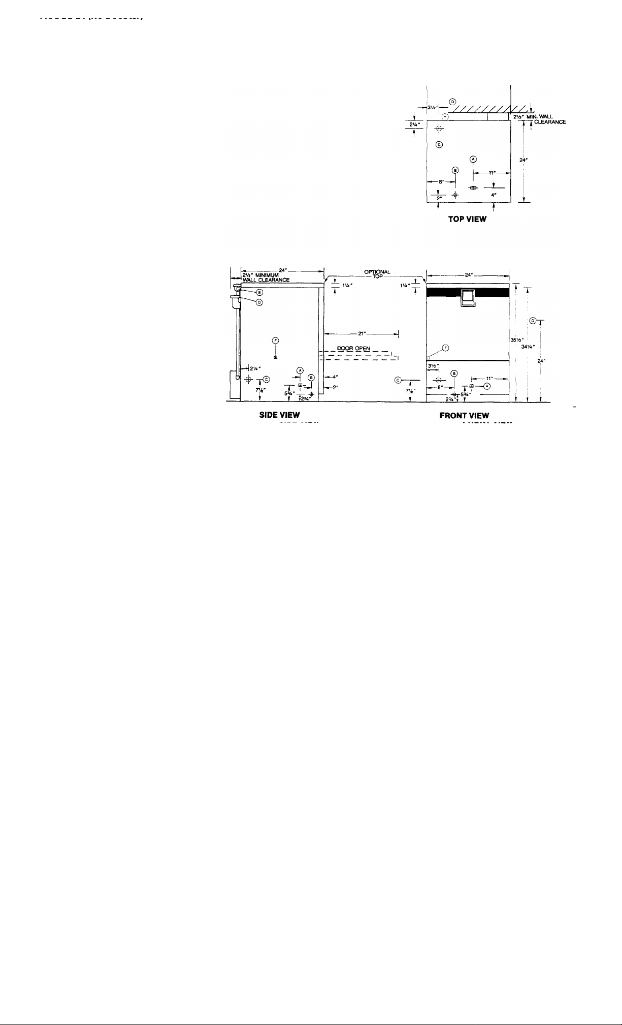
Dimensions
Height w/Top 36 1/4" ± 1/2"
Height w/o Top 341/2 a V1/2"
Width 24"
Depth 24"
Minimum Distance from
Wall to Machine 2 1/2"
Standard Table Height 34 1/2"
Maximum Clearance tor Dishes 14"
Legend
A. Electrical Connection.
B. Water Inlet - 1/2" Female Pipe
Thread. 2 1/2" High.
C. Drain Connection - 1 1/2" O.D.
D. Vented on Back. Cover underside of
countertop or table that will be affected
by moisture with suitable protective
material.
E. Rinse agent feeder connection.
F. Detergent feeder connection.
G. Maximum wall drain height with pumped
drain option.
NOTE: All dimensions from floor can be increased 1" with adjustable feet supplied.
Power/Connections
Model Model
24(F) 24B(F)
WASH PUMP MOTOR
Horsepower ELECTRIC HEAT WASH 1/2 1/2 OPERATING CAPACITY 24(F) 24B(F)
KW 1.0 1.0 Racks per Hour 21 21
ELECTRIC HEAT RINSE
KW N/A 6.2 Glasses per Hour 525 525
STANDARD RACK SIZE
Electrical Ratings 19 3/4 x 19 3/4 1 1
Model Volts Cycle* Phase Amps
15.5
1 (2
24,24F 115 60 24B,24BF 115/208-230 60
*50 cycle available
Water Requirements
Inlet Temperature— "F 180 140 WASH PUMP CAPACITY
Gal. per Hour 52.3 52.3 GalIons per Minute 60 60
Plow Pressure PSI 20 20 THERMOMETERS
Flow GPM 7.1 7.1 Wash-°F 140-160 140-160
Inlet—IPS 1/2" V2” Rinse- °F 180-195 180-195
Drain—O.D. 1/2" ½” SHIPPING WEIGHT - Pounds
(Gravity Feed Drain)
All specifications subject to change without notice.
wire)
1 (3
wire)
34.9 @
208v
37.8 @
230v
Performance/Capacities
Model Model
Dishes per Hour 525 525
OPERATING CYCLE
Wash Time-Seconds
Rinse Time-Seconds
Total Cycle-Seconds
WASH TANK CAPACITY
Gallons
Gallons
BASIC MODELS (Approx.) 200 200
CARTON SIZE (W x D x H) 30"x30"x38"
121
15 145
5.65
N/A
121
15
145
5.65
3
Page 4
MODEL 24 TABLE PACKAGE OPTIONS
GENERAL INFORMATION 24.1 PACKAGE
• The system combines the 24 or 24B dishwasher with a standard
Dishtable.
• 42" wall mounted overshelf in 1-X package.
• The Dishtable and overshelf are constructed of 18-8 304 series 16
gauge stainless steel.
• Heavy duty pre-rinse spray.
• 20"x20"x6" deep pre-rinse sink with molded scrap basket and rack
slide.
• C33/16" high backsplash.
• Left and right side panels for machine.
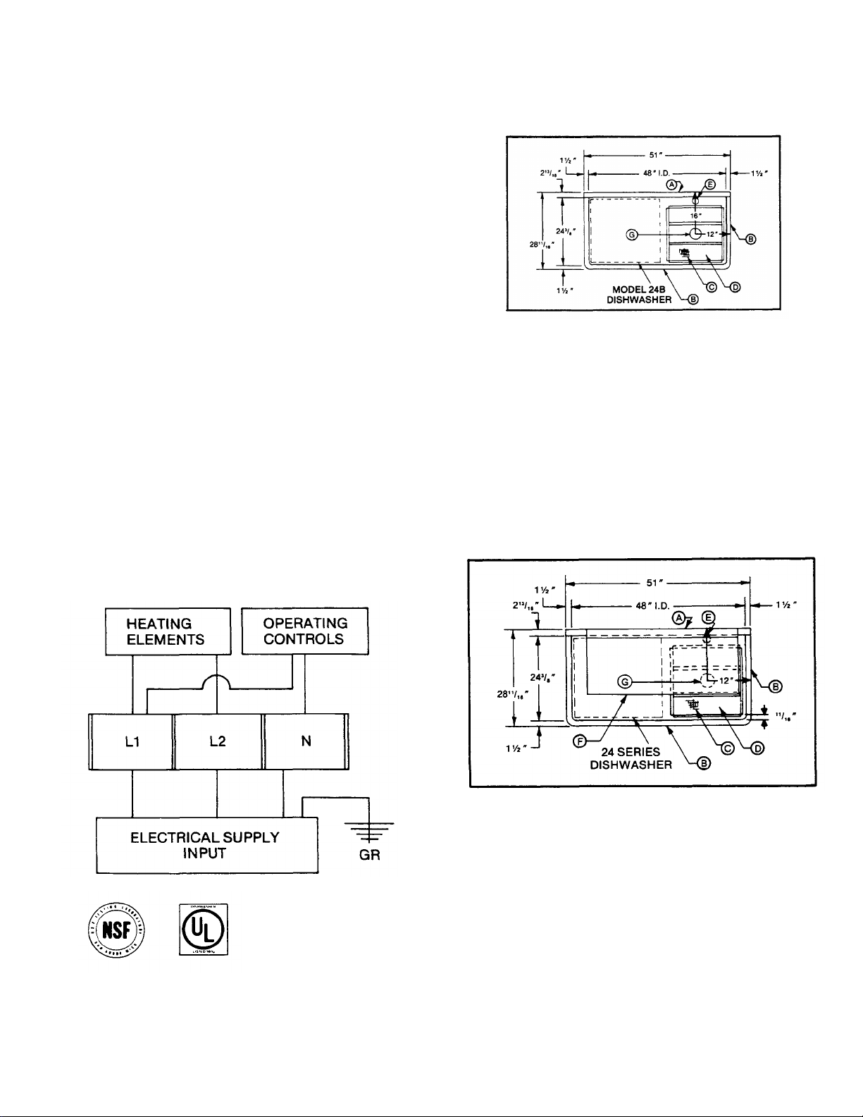
NOTES:
A. 633/16" High Backsplash, 33/4" " Turnback
at 45°.
B. 3" High, 1 1/2" Dia. Rolled Edge.
C. Scrap Basket & "H" Bars.
D. 20 " x 20 " x 6" Deep Pre-Rinse Sink. Drain Connection 25 1/2 ± 1/2" from Floor.
E. Heavy Duty Pre-Rinse 13/16" Hole Size.
F. Slanted Wall Mounted Overshelf. 20" x 42" Long.
G. 3 1/2" Hole for Drain, Basket Assembly.
16 GA. s/s N.S.F.
CONSTRUCTION 24-1X PACKAGE
ELECTRICAL
CONNECTION DETAILS MODEL 24B ONLY
Page 5

CONCEALED DAMAGE
IMPORTANT: FOR YOUR PROTECTION, PLEASE READ AND OBSERVE THE FOLLOWING:
This merchandise has been thoroughly inspected and carefully packed before leaving our warehouse.
If it is found that the shipment has concealed damage, PLEASE DO NOT RETURN IT TO US, but notify and file a
claim with the carrier at once, as follows:
CONCEALED LOSS OR DAMAGE:
Concealed loss or damage means loss or damage which does not become apparent until the merchandise has
been unpacked. The contents may be damaged in transit due to rough handling even though the carton may not
show external damage. When the damage is discovered upon unpacking, notify the carrier within forty-eight (48)
hours by phone and in writing, asking them to send their agent to fill out an inspection report. Save the cartons so
he may see them and be sure to note in the report any black marks, creases, tears, crushed corners or any other
marks indicating rough handling.
DO NOT RETURN DAMAGED MERCHANDISE TO US. FILE YOUR CLAIM AS ABOVE.
Page 6

GENERAL INSTRUCTIONS
(INSTALLATION)
REFER TO SPECIFICATION SECTION FOR FURTHER DETAILS.
Note: Read the following instructions carefully. Proper installation of your Jackson
Dishwasher will assure proper machine operation.
Uncrating 24:
1. Remove wooden blocks from carton.
2. Slide carton sleeve upward over top of dishwasher, set to one side.
3. Remove bolts holding wooden base to machine and screw in adjustable feet supplied. (Feet are
inside of dishwasher.)
4. Set dishwasher in place, ready for installation
Note: NSF base cradle must be field installed on all 'F' and 'P' models. Cradle goes under
machine and must be sealed in place using silicone sealant.
Installation Instructions:
1. The dishwasher can be leveled to the proper height by adjusting the feet on the four corners. The
front of the unit must be 1/4" to 1/2" higher than the back.
2. Refer to the dimensional data sketch for connections.
3. The drain from the machine is a GRAVITY DRAIN SYSTEM and should have the proper drop from
the machine to an open floor drain, vented to atmosphere. The drain connection is located to the left
rear of the machine when facing the machine's door. The drain fitting is I 1/2" OD tube size, 7" from
floor.
4. IMPORTANT — PLEASE READ — Located on the back upper left corner of the unit is a steam
equalizing vent. This vent in no way should be blocked or prevented from allowing steam to be
vented to the outside of the unit or from under the cabinet in which the unit is installed. Never pipe
the steam downward toward the floor. (SEE PAGE 5 IF IT IS BEING INSTALLED UNDER A
COUNTER.)
5. The electrical connections should be made to the terminal board located at the center front. The
terminals are marked L1, L2, and Neutral. Install proper circuit breaker and conduit size to conform
with local and/or national codes (standards). USE COPPER WIRE ONLY (#8 AWG).
Page 7
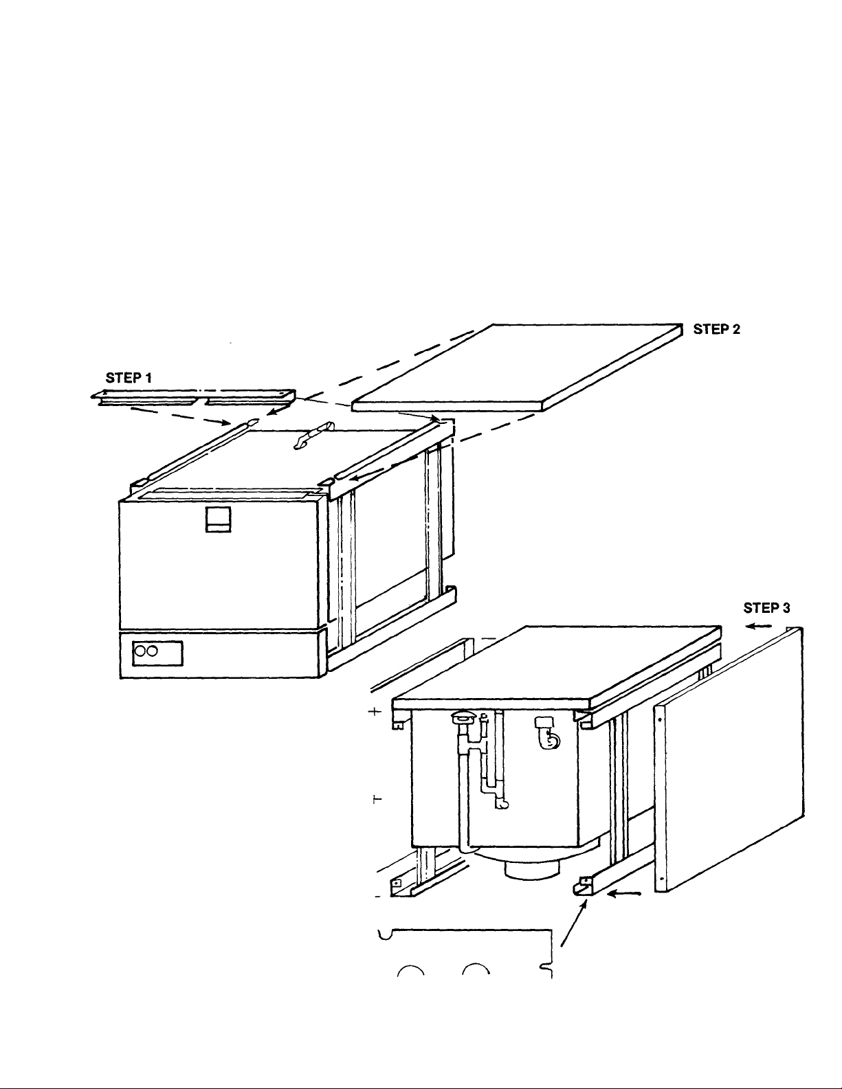
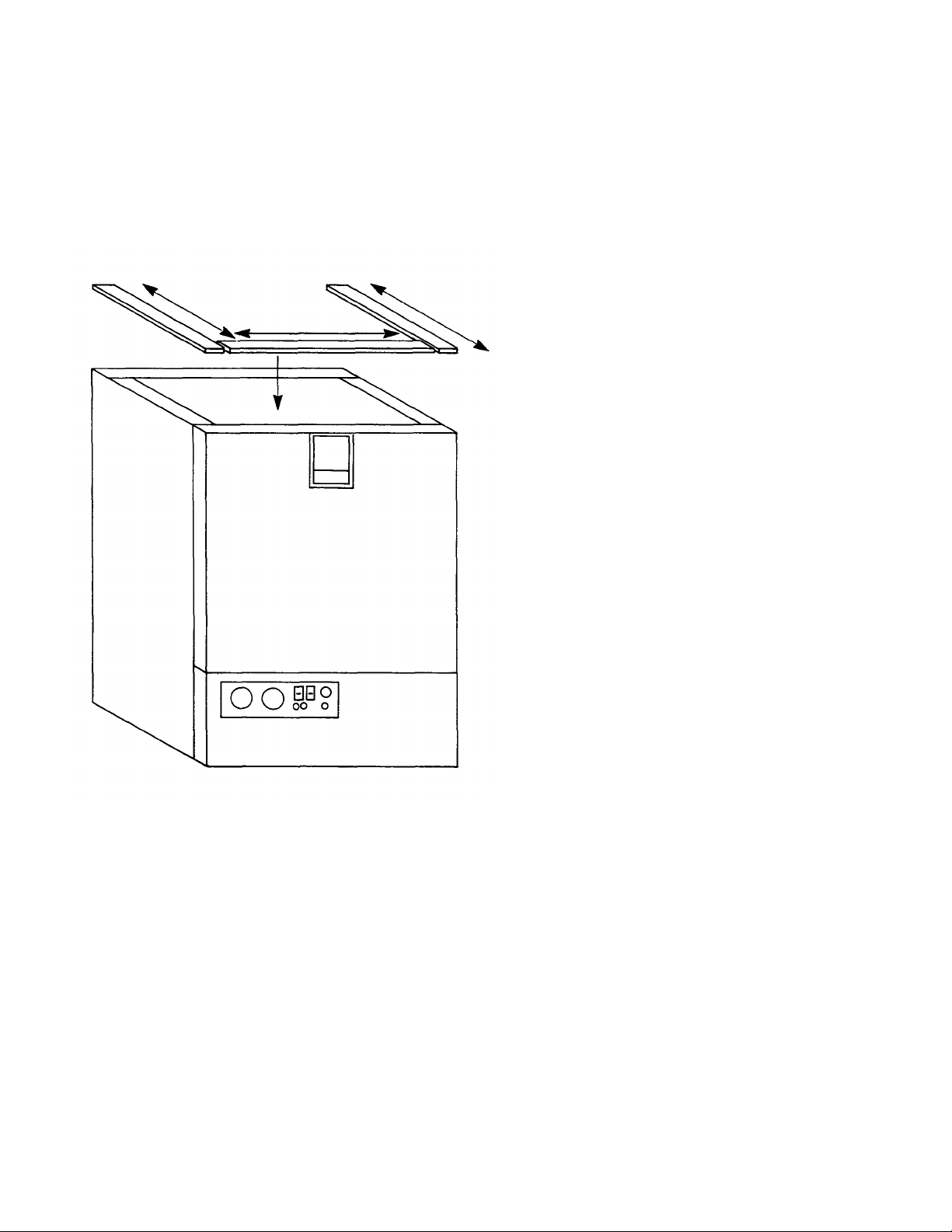
Installation of Top and Sides on 'F' and 'P' Models:
1. Insert rear barrier with angle facing out. Install prior to placing top on uit.
2. Place top on unit, making sure front lip is under flange, but does not interfere with latch or switch
mechanism. Place studs in holes on back of unit. Use 1/4-20 nuts.
NOTE: For 'P' models, omit steps 1 and 2.
3. Remove kickplate. Open door and place side panel lip at door opening. Work panel under top by
pushing with palm of hand. Put self-tapping screws in four places. Both side panels are installed in the
same way. Note: If unit being installed is an 'F' model, do not put the bottom rear self-tapping screw in
each panel until step 4.
4. 'F' models require a back panel. For installation, slide back panel behind lip of side panels and secure
with the two remaining self-tapping screws.
Page 8
Installation of Model 24 Top and Table gasket:
These instructions are to be used for applying the adhesive backed sponge rubber strip to the top of the
machine prior to setting the table in place.
Included with the Model 24 table is a 6 foot length of 1/4" thick x 1" wide sponge rubber adhesive backed
stripping.
Instructions for applying gasket:
1. Place one end of the stripping along the complete
side of the leg support flange and cut it off.
2. Repeat the same procedure along the other side.
3. Place the remaining piece along the front edge, fit it
in between the side pieces and cut it to length.
4. Remove the backing and set the strips in place.
Instructions for installation under a porous
counter top:
1. If possible, a hole should be cut through the counter
top directly above the equalizing vent. A piece of 1
1/4" OD pipe is then inserted through the hole into the
vent opening and piped to the outside.
2. If cutting a hole in the counter is not possible, then a
piece of stainless steel 36" wide by 36" long bend in
the middle at 90 should be centered directly over the
vent to allow the steam to condense on it when it
comes out of the vent.
3. It is very important that this vent be kept open and
cool air allowed to circulate around the unit.
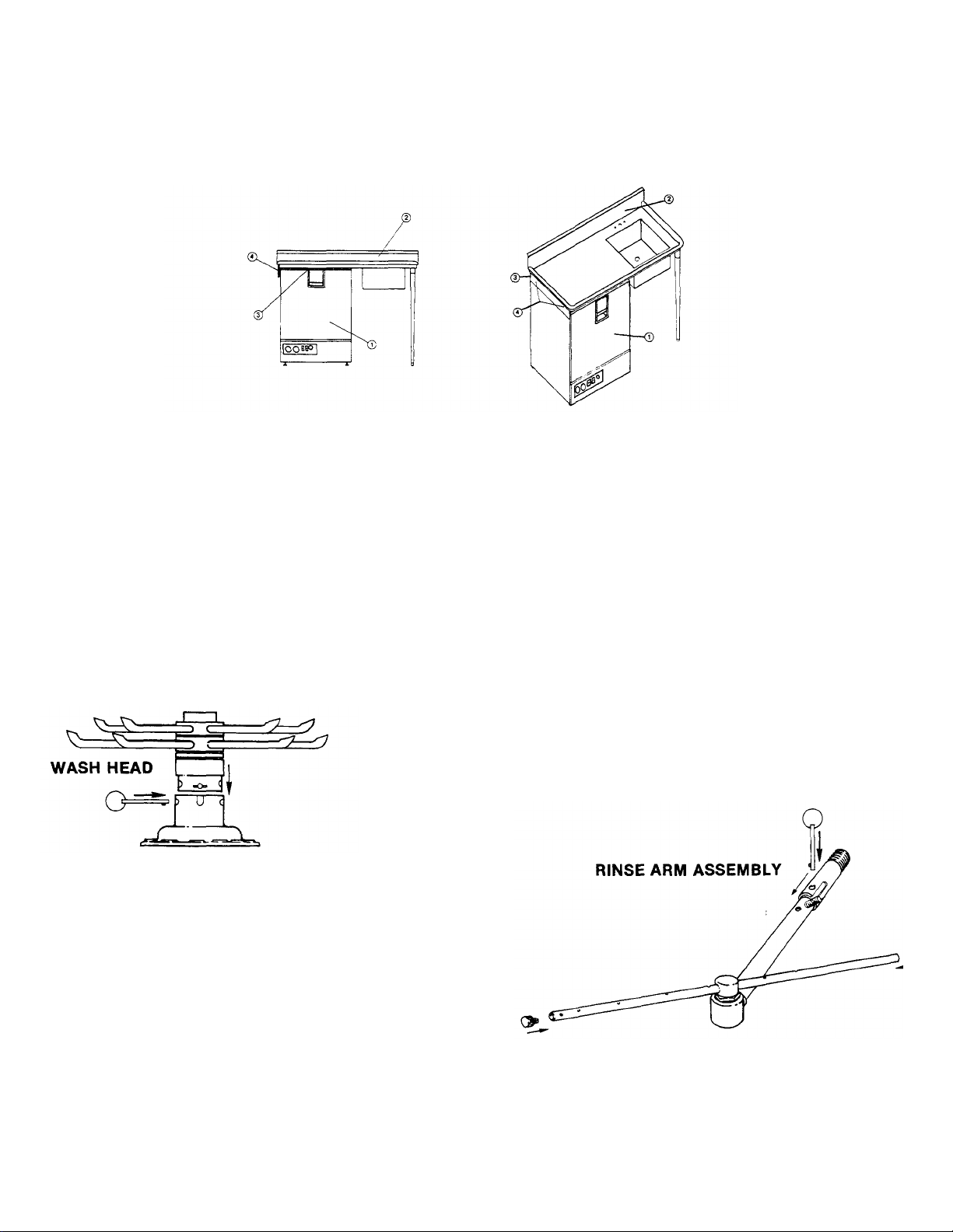
Installation of Model 24 Dishwasher Under Dishtable:
1. On the end of the table, locate bracket #4 opposite the sink end.
2. A square rubber gasket #3 is supplied and should be secured to top frame of dishwasher with
caulk or suitable adhesive.
3. Place dishtable #2 where it is to be installed and support the machine's end.
4. Slide dishwasher #1 underneath dishtable #2 so that the outside of machine is positioned against
the guide bracket #4. Make sure dishtable and dishwasher are in desired permanent location.
Page 9
5. Using the two holes in bracket #4 as a guide, drill two holes 9/64" diameter in the side panel of
machine. Note: Drill through first thickness of metal only.
6. Using the self-tapping screws supplied, screw them through bracket #4 and into the side panel of
machine until screws are tight.
Removal of Pan Strainer for Cleaning: (Wash and rinse head assemblies must be removed prior to
removing strainer.)
1. Turn machine off and drain by depressing drain switch and releasing.
2. Remove holding pin from rinse feed pipe, remove rinse head assembly by pulling forward.
3. Remove holding pin from upper pump housing, wash head may now be lifted out.
4. Pan strainer now accessible, lift out and clean thoroughly.
5. Clean around pump intake with bristle brush.
6. Replace stainer pan.
7. Re-install wash and rinse head assemblies.
8. Clean strainer pan daily or as needed to insure proper machine operation.
Installation of Wash Head and Rinse Arm Assemblies: (Items disassembled for shipment)
1. Line holes up on wash head assembly to match slots in pump housing.
2. Insert wash head assembly down into upper pump housing as far as
possible.
3. Insert retaining pin to secure wash head to pump housing.
1. Line up stud to match with slot in nipple.
2. Insert rinse arm assembly into female receptical
protruding through back of machine.
3. Insert lanyard pin to secure rinse arm assembly
properly.
4. Make certain end plugs are secured properly in
rinse tubes.
Page 10

INSTALLATION CHECKLIST
Please check off the following items as they are completed. All items must be completed and checked off
before proceeding to machine operation.
In the event that installation information is needed, please call one of Jackson Products authorized
service agencies, dealership where purchased or Jackson Products Company Technical Assistance
(813) 985-8144.
1. Is machine pitched up 11/4-11/2 inch in front than rear?
2. For gravity drain systems — is machine's gravity drain connected to a open floor drain "vented to atmosphere"?
3. Is machine service voltage at L1 and L2 208-230 volts?
4. Is machine service voltage at L1 and neutral 104-120V?
5. Is machine properly grounded?
6. Is machine service breaker properly sized to total amp load as specified on data plate?
7. Is machine supplied with 140°F hot water at 20 PSI flow pressure with capacity of 52.3 gallons per hour?
8. Is water supply line to machine a minimum of 1/2 inch?
9. Is a pressure reducing valve installed on inlet water line for pressures greater than 20 PSI flow?
10. Is equalizing vent vented to atomopshere?
11. Is pump intake strainer installed?
12. Is lower rinse spray arm installed?
13. Is wash spray head installed?
Page 11

GENERAL INSTRUCTIONS
(OPERATION)
Note: Read the following instructions carefully. Proper operation of your Jackson
Dishwasher will assure clean and sanitized glasses and dishes, at optimum efficiency. Dish
Preparation:
1. Scrape dishes thoroughly.
2. Pre-wash dishes by soaking or with hose.
3. Place dishes and cups in dish rack, cups upside down.
4. Place glasses and silverware in combination glass-silverware rack, glasses upside down. Scatter silverware
loosely on bottom.
Note: Silverware in the upright position washes and rinses better than lying flat. These silverware
compartment racks are available through your dealer or Service Agency.
24B/BF Operating Instructions:
1. Install pan strainer and the wash and rinse arms. Close the door and push until the handle latches.
2. Push the On/Fill-Off/Drain switch to the up 'ON/FILL' position. The machine power light will come on and so will
the rinse heaters. The machine will begin to fill automatically and stop by itself.
3. After the machine has completed filling, open the door and put in a rack of soiled dishes. Close the door.
4. After the door has been closed, the cycle light will come on. There will be a 2-second delay before the wash
cycle begins.
5. The machine will wash for 130 seconds and rinse for 15 seconds. After the cycle has finished, the cycle light will
go out.
6. Open the door and remove the sanitized dishes. The machine is ready for another cycle.
7. To manually wash, push the manual wash switch to the up 'Manual' position. The machine will wash indefinitely.
This function can also be used to delime. To resume normal operation, push the manual wash switch to the
down 'Auto' position.
8. To drain the machine, close the door and latch. Push the On/Fill-Off/Drain switch to the 'OFF' position. All
machine functions will be off. Push On/Fill-Off/Drain switch down to the momentary drain position. This will begin
the drain cycle. After the machine is drained, it will turn itself off.
9. Open the door. Remove and clean the pan strainer and the wash arms.
10. Wash heater protection is provided by two means. Primary protection is given by the water level control which
senses the water level with a probe. If this should fail due to excessive build up on the probe, the secondary
thermal protection will cut out the wash heater before damage occurs.
11. When the secondary heater protection has been used, it will be indicated by the illuminated red reset light.
The following steps are necessary in this situation:
A. Turn off power supply.
B. Open the door and remove the wash and rinse arms and the pan strainer.
C. Locate the probe. It is in the wash sump on the left hand side.
D. Using a deliming compound and a brush, clean the probe.
E. Reinstall the wash and rinse arms and the pan strainer.
F. Push the reset button, located above the reset light.
G. Push On/Fill-Off/Drain switch to the 'ON/FILL' position. The machine should begin
to fill. If it does not and the reset light comes on again, call an authorized service
agency.
Detergent Recommendations and Rinse Additives:
We suggest that you contact your local Detergent Specialist for the correct detergent and rinse additives for your
area. Dump the detergent on the pan strainer. This may have to be increased or decreased to obtain satisfactory
results.
VERY IMPORTANT: Do not use a domestic type detergent in this machine at any time. This type of detergent may
damage and/or obstruct pump operation and may cause corrosion to tank.
10
Page 12

GENERAL INSTRUCTIONS
(PREVENTIVE MAINTENANCE)
USER SERVICEABLE AREAS
(THE FOLLOWING IS TO BE PERFORMED DAILY OR AS NEEDED.)
Note: Read the following instructions carefully. Proper maintenance of your Jackson Dishwasher
must be conducted for warranty consideration.
1. Remove all lime and corrosion deposits.
a. Fill the machine with wash water as would ordinarily be done for washing.
b. Open door and place one cup or less of de-liming compound into the water. The
compound is available from your detergent supplier.
c. Turn on the manual wash switch and allow to wash for five minutes.
d. Open door and examine the interior. All lime should be removed and parts should be
shiny. If not, allow to wash for longer period.
e. After the interior is clean, with door closed, empty the wash water by turning switch to
the "off/drain" position. Refill machine and allow to run for two minutes, then again
drain the wash reservoir.
2. Clean around overflow strainers and drain hole.
a. Clean around overflow and strainer pan.
b. Clean around pump intake (toothbrush makes excellent tool for cleaning).
3. Clean Y-strainer on incoming water line. (Water to machine must be turned off for this operation)
a. Remove plug and clean strainer.
4. Clean rinse tubes.
a. Remove rinse assembly by disconnecting rinse feed pipe and removing end plugs on
lower rinse.
b. Clean all rinse tubes and feed pipes with special brush supplied.
c. If spray holes in the rinse tubes are clogged, they may be cleaned with a pointed
object.
5. Clean water level probe in sump with brush to remove any scale or build-up.
6. Clean wash head assembly.
a. Remove pin holding wash head assembly to pump.
b. Clean assembly at sink by flushing water through spray jets.
c. If spray jets are still plugged, use sharp object to dislodge and flush again.
d. Reinstall wash and rinse assemblies. (See page with instructions.)
7. Clean any deposits which may have built up on exterior moving parts.
a. Clean around door gasket.
b. Using a soft bristle brush, clean around switches on exterior of control panel. (Use no
water.)
c. Use soft bristle brush, dip in wash tank water and scrub inside door around gasket
and hinges. Use clean cloth or paper towel to wipe off loose residue.
HARD WATER AREAS
Very Important: Areas known to have hard water (7-10.5 grains per gallon) or very hard water (10.5 + grains
per gallon) must consider installing a water softner system to prevent scaling of heater
elements and water probes which could cause damage not covered under normal warranty
conditions.
Page 13

REMOVAL of RINSE and/or WASH
HEAD ASSEMBLIES
(GENERAL INSTRUCTIONS)
USER SERVICEABLE PARTS
(THE FOLLOWING IS TO BE PERFORMED DAILY OR AS NEEDED.)
1. Drain unit by placing switch in the off/drain position.
2. Open the door and allow the unit a few minutes to cool off.
3. Remove the pin holding the rinse feed pipe. Pull the feed pipe out of the nipple and lay it to one
side.
4. Remove wash head assembly by pulling out the holding pin and lifting assembly. Place the wash
head on a table for disassembly.
5. Locate Allen head set screw in the wash head cap, insert Allen wrench and loosen screw by turning
counterclockwise.
6. Turn wash head cap counterclockwise until cap is removed and put cap in safe place.
7. Remove 1/4" stainless ball bearings carefully and put it in a receptacle in a safe place.
8. Lift and remove small manifold with short tubes. Put it in a safe place.
9. Remove 1/4" ball bearing in similar method to step #7.
10. Lift and remove large manifold with large length tubes similar to step #8.
11. Clean ball bearings by soaking in de-liming solution.
12. Ball bearing race ways may be cleaned by either brushing with de-liming solution
(toothbrush makes excellent tool) or gently clean by rubbing with fine sandpaper or emery cloth.
13. Rinse ball bearings and manifolds thoroughly.
14. To reassemble, first fill lower race to capacity with 1/4" ball bearings, then remove one. This will
give proper movement needed during rotation of assembly.
15. Replace lower manifold and fill race fully with 1/4" ball bearings. Repeat, removing one only.
16. Replace upper manifolds and repeat necessary parts of step #14.
17. Replace wash cap by screwing on center shaft clockwise, finger tight.
18. Back off wash cap about 1/4 turn and tighten Allen set screw.
19. Rotate manifolds in opposite directions; see if they rotate freely. A rule of thumb is to select the
longest tube in the bottom manifold and make sure it moves up and down at least 1/8" and no more
than 1/4".
20. Replace wash head assembly and rinse arm.
21. Close the front door and refill dishwasher.
22. Run through several cycles and recheck wash arms for easy movement. Adjust if necessary.
Note: It Is Important that the wash head and rinse arm be kept clean and free from
obstruction. Improper maintenance to these assemblies may create problems not
covered under normal warranty conditions.
Page 14
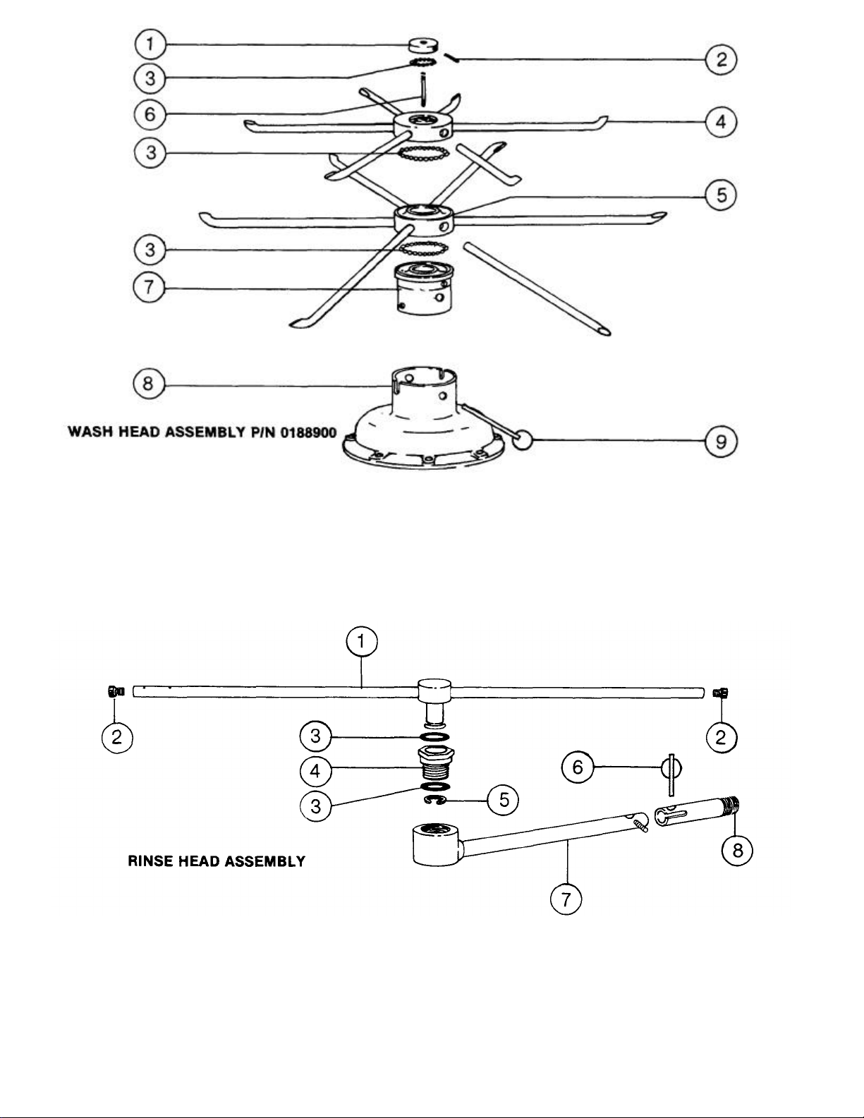
ITEM
w/TUBES
w/TUBES
1. 0186500 WASH HEAD CAP WITH RACE 6. 0187500 WASH HEAD CENTER SHAFT
2. 0187000 WASH HEAD CAP SET SCREW 7. 0193601 WASH HEAD FIXED RACE
3. 0194000 WASH HEAD BEARING 1/4" SIS
4. 0189000 WASH HEAD SMALL MANIFOLD 9. 0188601
5. 0189500 WASH HEAD LARGE MANIFOLD
P/N DESCRIPTION ITEM P/N DESCRIPTION
8. 0109600 UPPER PUMP HOUSING
WASH HEAD ASSEMBLY
RETAINING PIN w/RING
ITEM
1. 0125200 RINSE HEAD ARM 5. 0126500 RINSE HEAD SNAP RINGS S/S
2. 0126800 RINSE HEAD END PLUGS 6. 0137301 RINSE FEED PIPE LANYARD PIN
3. 0126000 RINSE HEAD NYLATRON WASHER 7. 0137200 RINSE FEED PIPE (LOWER)
4. 0125500 RINSE HEAD HEX BRUSHING S/S 8. 0137202 RINSE FEED PIPE NIPPLE
P/N DESCRIPTION ITEM
P/N DESCRIPTION
Page 15
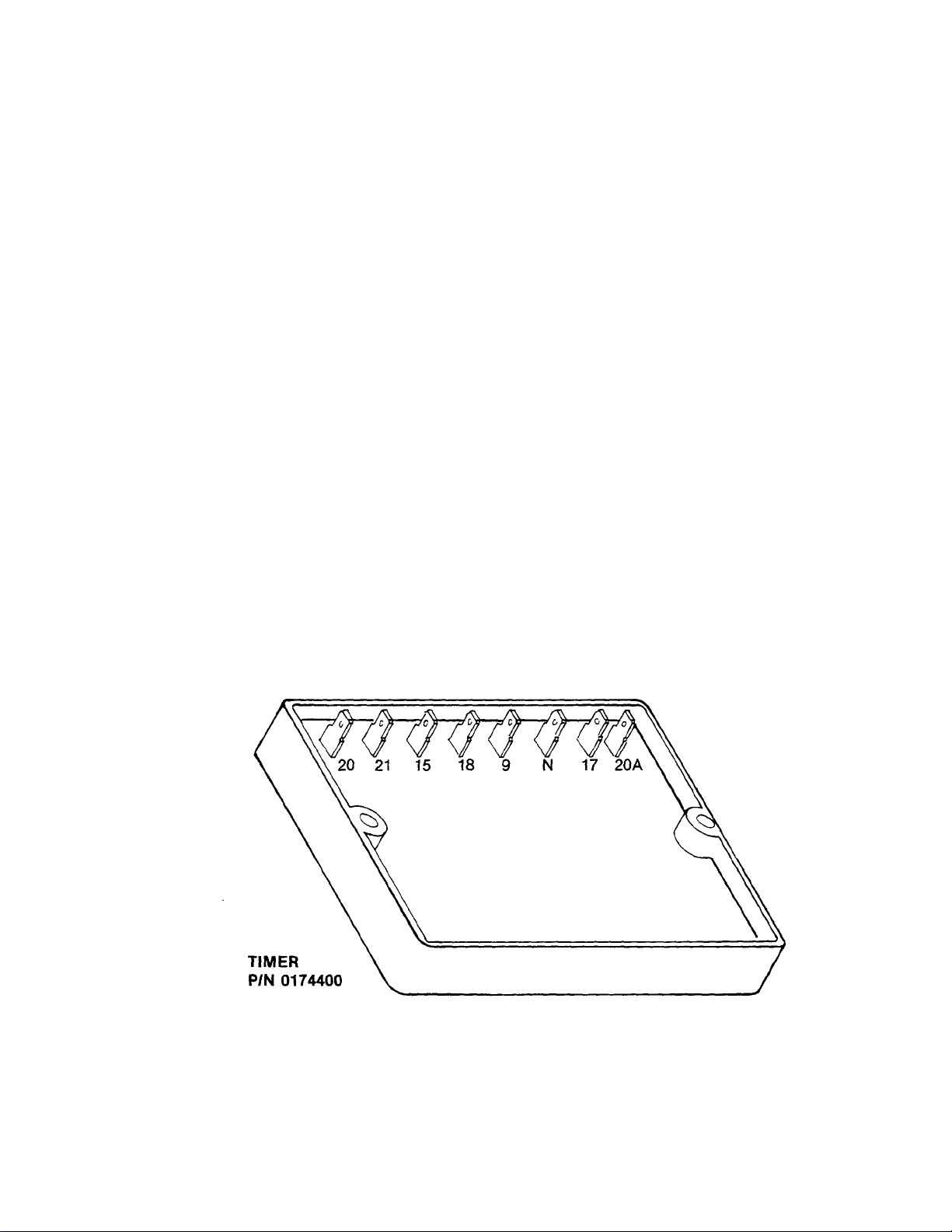
TIMER for MODEL 24
DISHWASHERS
General Description:
The timer is a solid state, 4 channel CMOS device with a 120V, 50 or 60 cycle, 1 amp rating. All
components are environmentally encapsulated and quick connect terminals are marked for
corresponding wires.
Principle of Operation:
Wash cycle function: (Machine must fill before cycle will start.) Upon closure of door switch,
cycle light will come on and remain on for the 150-second cycle. At the same time, a 2-second
rinse preheat interval will begin. After the preheat, the wash cycle will start and last 130
seconds. Between wash and rinse, there is a 4-second dwell followed by a 15-second rinse.
Cycle by opening and closing door switch at the end of cycle or at any point in the cycle.
Drain cycle function: (Power switch must be in off position and door switch closed.) When
power switch is pushed to the drain position and released, a holding circuit is established
between R4 drain relay and the timer. The machine will drain for 60 seconds and then break the
holding circuit. Cycle is reset by opening and closing door switch and pushing power switch to
drain and releasing.
Very Important: At no time are there to be any aftermarket equipment electric
connections made to any Input or load circuits of this timer. Consult
factory for further information.
Page 16

FUNCTION of SWITCHES, CIRCUIT
BREAKER and INDICATING LIGHTS
On/Fill
Off/Drain
Switch: P/N
0155600
Power Light:
P/N 0083518
Door Switch:
P/N 0164000
Cycle Light: P/N
0083507
Manual Wash
Switch:
P/N 0159700
Heater Reset
Button:
P/N 0169601
This switch serves as the main control for the unit. When pressed into the 'on' position, it
activates the heater controls, the automatic fill and readies the unit for the wash cycle.
When turned off, all power is off. When pushed to drain position and released, the unit
will drain and turn itself off.
This light comes on when the unit is turned on and goes off when the unit is turned off.
Located on top of the unit, behind the latch bracket, this switch serves three functions.
When the door is opened, it will reset the timer to the cycle starting position. When door
is closed, it will start the automatic cycle. If door should be opened during a cycle, it
would act as a safety switch by turning the unit off.
This green light comes on only when the automatic cycle is in progress and goes off
when the cycle is complete.
This switch is used to bypass the timer and operate the wash pump manually. The wash
pump will run as long as this switch is 'on'. Its prime purpose is to extend the wash
period for heavily soiled dishes, but it may be used for deliming.
This is the reset button on a thermostatic overload. Its purpose is to provide a secondary
protection for the wash tank heater element. If the heater element should come on while
the wash tank is empty, this button would pop out, turning off the element and signaling
a problem with the automatic fill.
Reset Light:
P/N 0083518
This light comes on only when the heater reset trips off. Its purpose is to signal that
there is a problem.
Page 17
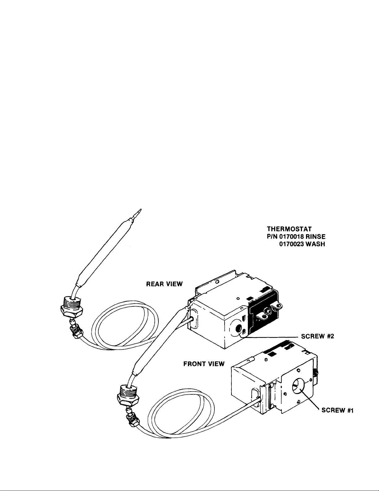
THERMOSTAT ADJUSTMENT
The thermostat can be adjusted by turning screw #1 (see picture) on the thermostat control box cover.
(Remember the present setting, in case the problems are elsewhere in the control circuit.) A CW rotation is
used to obtain a lower temperature setting and a CCW rotation is used to obtain a higher temperature setting.
A 1/8 turn of screw #1 changes the temperature approximately 15 °F. If screw #1 is turned all the way to its
stop in either direction, adjust screw #2 as follows.
Note: Do not touch the screw sealed with red paint. When adjusting screw #2, power should be
disconnected during adjustment.
Set screw #1 so that it can be turned equal distances in either direction, then:
— if screw #1 stopped while turning in CW direction, turn screw #2 in CW direction, slowly and only 1/8 of a
turn or less per complete cycle of the unit.
— if screw #1 stopped while turning in CCW direction, turn screw #2 in CCW direction, slowly and
only 1/8 of a turn or less per complete cycle of the unit.
Three-fourths of a turn will bring the thermostat to approximately the same setting obtained where screw #1
stopped. Check the present temperature setting before attempting any further adjustments. Use screw #1 for
any further adjustments.
Making large moves in adjusting may cause misalignment, thus increasing chances that further adjustment
cannot be made and thermostat will have to be replaced.
Page 18

RINSE TANK HEATER SYSTEM
Function:
The Rinse Tank Heater System is electrically connected in the circuit with the control system functioning
on 110/130V and the power system functioning on 208/230V for both systems. The heat circuit is
controlled by the 'on/fill' switch (mounted on front panel) and a thermostat (mounted near thermometer)
which activates the coil on the heat relay. When higher temperature is required, power is applied to the
heaters when the contacts of the heat relay are closed. Should the rinse tank thermometer read either
too high or too low, follow checkout below.
Checkout of Heater System for Rinse Tank: (Refer to drawing, Figure #2)
Note: The following checkout should be done by a qualified service person or electrician.
1. Turn off power to machine by tripping circuit breaker to 'off position.
2. Remove front kick plate below door.
3. Make sure rinse temperature is below 180°.
4. Reapply power and observe heat relay (2-pole) letter G, figure 2, as 'on/fill' switch is turned on and
off several times.
AA If heat relay contacts do not close, with 'on/fill' switch on:
1. Check power supply at Position 1 on terminal board X. Voltage should be 110VAC.
2. Check Position 3; there should be 'zero' volts there. If not, readjust thermostat per thermostat
instructions.
3. If voltage is being applied to Position 1, then the relay should be replaced; coil on relay probably
defective.
BB To determine if elements are working:
1. There's an insulated movable bar on the heat relay across the top of the two
contacts. With an insulated probe, depress the bar and observe rinse thermometer;
the temperature should rise noticeably in a minute or two. If it moves very slowly, it
would indicate that one element is defective. If it moves consistently higher at a
good rate, the elements are okay.
Note: A check with an amp probe, if available, can be made.
The element should draw 22-25 amps. Replace element if found defective.
CC If the heat relay closes:
1. Check power supply at Position 4 on terminal board X, right hand view. It should be 220V
approx. If not, check circuit breaker at customer's panel; replace if defective.
2. Check power at Position 5; voltage should be 220V. If not, check connections and wires for
breaks; replace as necessary.
3. With 'on/fill' switch on and relay closed, check power at Position 6; voltage should be 220V. If
not, replace heat relay.
4. If No. 3 above checks out okay, check at Position 7; voltage should be 220V. If not, check wiring
from heat relay to elements for loose connections or broken wires;
repair as necessary.
Page 19

A - ON/FILL SWITCH F - RESET LIGHT
B - WATER LEVEL CONTROL G -RELAY
C -THERMOSTAT H - RINSE HEATER
D - (WASH) RING HEATER X - TERMINAL BOARD
E - THERMOSTATIC OVERLOAD
Page 20

WASH TANK HEATER SYSTEM
Function:
The Wash Tank Heater system is electrically connected in the circuit, with the control system functioning
on 110V and the power system functioning on 208/230V. (On models without built-in booster, power
circuit is 110V.) The heat circuit is controlled by the water level control (mounted right side of control
panel), thermostat (mounted near thermometers), and thermostatic overload (located beside manual
wash switch), and wash heat relay (R-2). When higher temperature is required, power is applied to the
heater when the contacts of the heat relay are closed. Should the wash tank thermometer read either too
high or too low, follow checkout below.
Checkout of Heater System for Wash Tank: (Refer to drawing, Figure 1.)
Note: The following checkout should be done by qualified service personnel or electrician.
1. Turn off power to machine by turning circuit breaker to 'off position.
2. Remove front kickplate below door.
3. Turn circuit breaker back on.
4. With door closed and latched, turn the 'on/fill' switch to the 'on/fill' position. Machine should start to fill
automatically. Observe the water level control, letter B. When machine has filled for approximately
25 seconds, contact points in clear plastic relay should move, and an automatic cycle should start.
Note: This will happen everytime 'on/fill' switch is turned off and back on.
AA If water level control relay doesn't close, refer to page on Water Level Control function and checkout.
BB If water level control is functioning properly:
1. Check voltage at Position 1 on terminal board X. Voltage should be 110.
2. Check Position 3, Figure 1; there should be no voltage. If there is voltage, then adjust thermostat
(refer to page on Thermostat Adjustment).
3. Check reset light. If light is on, push reset button.
4. Check voltage at Position 2. There should be no voltage. If there is voltage, relay should be
replaced; coil is probably defective.
5. Check Position 5, Figure 1. Voltage should be 220. If not, check Position 8. There should be
220V.
6. Temperature should rise slowly. A check with an amp probe would indicate if the element is
working. Replace element if defective.
Page 21

WATER LEVEL CONTROL
AS USED ON 24
P/N 0204400 (110V, 60 cycle)
Function:
The water level control device is utilized on this machine to automatically control the filling of the
wash tank and the activation of the wash tank heater.
Note: All electrical checks should be made by qualified service personnel.
The control is a single probe resistance sensing device designed to maintain water level. When
water level reaches the probe and covers it, a fixed time delay of 25 seconds is initiated. When
the delay times out, the electromechanical relay energizes, opening the 'Auto/Fill' circuit and
closing the wash heater circuit. If the water level drops below the probe, the relay will deenergize, opening the wash heater circuit and closing the 'Auto/Fill' circuit.
Symptoms of Level Control Failure:
1. 'Auto/Fill' will not shut off when water reaches the proper level. (Check sensitivity
adjustment.)
2. Machine will partially fill.
Proceed with Checkouts:
1. Remove power source to machine by moving circuit breaker to 'OFF' position.
2. Remove screws holding lower kick plate to the front of machine and locate water level
control. (See sketch below.)
3. Remove, mark and insulate (for easy replacement), wires going to pin numbers 4 and 5.
4. Re-apply power. Turn on 'ON/FILL' switch. With an insulated wire, connect jumper wire
between pins 4 and 5. (12 volt system)
5. Wait for 25 seconds. The electromechanical relay will energize. If this occurs, control can be
deemed operational; then other causes should be explored.
6. If relay doesn't operate, check GND and input voltages. Replace if needed.
7. Remove power source once again and replace wires that were removed in step three to
original pins. (See trouble shooting section for other possible causes.)
Page 22

SERVICE INSTRUCTIONS
(INCOMING WATER SOLENOID VALVE)
SOLENOID VALVE
P/N 0142100
(110V, used on 60 cycle machine)
To take the valve apart:
Disassembly — These valves may be taken apart by
unscrewing the bonnet and the enclosing tube assembly
from the valve body assembly. See Fig. 3. After
unscrewing, carefully lift off the bonnet and enclosing
tube assembly. Don't drop the plunger. The "O" ring seal
and diaphragm cartridge can now be lifted out.
Be careful not to damage the machined faces while the
valve is apart.
To Reassemble — Place the diaphragm cartridge in the
body with the pilot port extension UP. Hold the plunger
with the synthetic seat against the pilot port. Make sure
the "0" ring is in place, then lower the bonnet and
enclosing tube assembly over the plunger. Screw
bonnet assembly snugly down on the body assembly.
Possible Problems
Pilot Port extension #1 clogged Hole #2
clogged
Remedy
Pass heated straight pin through hole #2 or
clean hole #1
Page 23

BEWARE of COUNTERFEITING!
No, not money, but counterfeiting of parts that could cost you hundreds of dollars.
The only difference between this form of counterfeiting and monetary counterfeiting is that is may be
legal. In our economy it's called competitive business. However, as an end user, are you aware of your
liability if such a part fails and causes injury to one of your customers or employees? Your customer may
bring suit against you, and your employee may file a workmen's compensation claim. In such a case, do
you have sufficient recourse against the company from which you bought the part? Do you realize that
many of these companies may not carry adequate liability insurance to protect themselves from such a
claim?
Factory Authorized parts are purchased directly from the manufacturer that produces the equipment.
Typically, the manufacturer assumes responsibility for the replacement parts, when installed correctly.
These parts have passed numerous rigid tests and are either UL (electrical), AGA (gas), or NSF (all)
approved.
Most manufacturers will void the warranty of equipment if counterfeit parts are installed. In some cases
installation of counterfeit parts will relieve the manufacturer from liability for the equipment. No one can
argue that counterfeit parts are competitively priced — although sometimes at the expense of quality.
The companies that manufacture counterfeit parts often do not have the same overhead as the
manufacturer that produces the original equipment — expenses incurred for continuous rigid testing,
inspection, insurance, warranty service and the like.
The next time you purchase a replacement part for "the best price", ask if it is a FACTORY
AUTHORIZED part. Then you can consider if the risk is worth the "savings".
If you are uncertain whether you have purchased a counterfeit part, please bring it to us for inspection.
We are pleased to help you reduce your liability — and costs — whenever we can.
GENUINE PARTS PROTECT YOU ALWAYS.
Page 24

TROUBLE SHOOTING GUIDE
PROBLEM CAUSE SOLUTION
Water overflow out bottom of Machine not level. Level machine.
front door when wash pump
is operating. Overflow drain clogged. Remove obstruction, checking
Wash motor doesn't operate on Wires broken or loose. Check all wires in the motor and
manual wash.
Note: The motor starting relay is utilized to insert a starting field in the wash pump motor, once the
motor has gained speed, the running winding will then take over and the starting winding will be
removed when the relay kicks out.
Motor runs on manual wash but Defective timer. Replace timer.
doesn't operate on automatic
(rinse operates okay on both
manual and automatic cycles.) Defective circuit in manual Replace switch.
No water comes through the Hand water valve to machine Turn on water valve.
rinse arms when the 'on/fill' not turned on.
switch is depressed.
Little or no water coming Limed up rinse heads or Begin by cleaning rinse heads
through rinse assemblies. piping. using instructions for de-liming.
Water level in machine's Solenoid valve not closing at
wash reservoir too high. end of fill or rinse cycle
Detergent foaming. Reduce quantity of detergent.
Equalizing vent blocked. Allow free steam flow.
Defective manual wash Replace.
switch.
Bad bearing, noticeable by Replace.
noisy bearings or locked
drive shaft.
Defective motor starting Replace.
relay. (Typical - motor
hums.)
wash switch.
Defective coil on Replace coil.
solenoid valve.
Probes are dirty or coated. Clean probes.
Defective water level control. Replace.
Water pressure low. Increase pipe size to machine.
Slight tilt to rear
inside of machine first.
causing excessive water
problem.
reconnect as necessary.
If this isn't satisfactory, then
clean the rinse feed pipes.
Page 25

TROUBLE SHOOTING GUIDE
PROBLEM CAUSE SOLUTION
Rinse doesn't operate on Timer defective. Replace.
automatic during timed cycle
(but does operate on auto/fill
operation).
Rinse water runs continuously Defective plunger in Replace plunger.
with circuit breaker controlling solenoid valve.
machine turned off.
Defective diaphragm in Check both holes in diaphragm
solenoid valve. cartridge to insure that they
Note: In disassembling solenoid valve, use instructions shown on separate page.
Rinse water runs con- Defective water level control. Replace.
tinuously with power applied
to machine, but when circuit
breaker to machine is turned Probes are dirty or coated. Clean probes.
off, water stops.
are open. The one on the outside
perimeter should be the size of an
ordinary straight pin. If it's not,
heat a straight pin and put it
through this hole to enlarge. If
this fails to correct situation,
replace diaphragm.
Note: Excessive water line pressure can cause water to continually run even though the power to the machine is
turned off. Check specifications for required pressure.
Wash temperature not at Defective thermometer. Using a thermometer (fast
required reading on
thermometer.
Rinse temperature not at Check out rinse heat using
required temperature, causing heater checkout system page
wash temperature to be in manual.
lowered during rinse cycle.
Note: Any switches, water level controls, heater elements, relays or contactor that have to be checked out, can be
done using the heater checkout system page.
reading type that's known
to be correct), insert in wash
rerservoir and check reading
against wash thermometer on
machine. If machine thermometer
isn't correct within three or four
degrees, replace.
Page 26

TROUBLE SHOOTING GUIDE
PROBLEM CAUSE SOLUTION
Thermostat defective. Adjust using instructions on thermostat
Water level protection control defective. Replace. (Auto/fill would run continuously.)
Heater element defective. Replace.
R-2 defective. Replace.
page and heater system's checkout page.
Replace if necessary.
Rinse water not at required temperature
range.
After filling machine with water, leakage
began at lower front panel without machine
operating or at end of rinse cycle.
Machine doesn't drain when
'off/drain' switch is depressed.
Thermometer's defective. Replace.
Thermostat defective. Adjust using instructions on thermostat
page and heater system's checkout page.
Replace if necessary.
Defective heater relay on contactor. If defective, replace. See note on heater
system above.
Overflow drain clogged. Clean away obstruction.
Drain solenoid clogged. Defective switch. Remove obstruction. Replace.
Defective motor or motor start relay. Replace.
Defective drain solenoid. Replace.
Note: The drain pump of this machine is part of wash motor, so if was motor operates properly drain system should work.
Defective timer. Replace timer.
Defective relay. Replace.
Page 27

FRONT VIEW
ITEM P/N DESCRIPTION
1. 0052700 DOOR HANDLE ASSEMBLY
2. SWITCHES
3. 0052600 FRONT DOOR
4. 0125100 RINSE ASSEMBLY, UPPER
4A. 0125200 RINSE ASSEMBLY, LOWER
5. 0188900 WASH ASSEMBLY
6. 0005700 BOOSTER TANK
7. 0060000 HEATER ELEMENTS
8. 0142100 SOLENOID, (110V, used on 60 cycle machines)
9. 0185000 VALVE FOR HEALTH INSPECTOR GAUGE
10. 0153600 "Y" STRAINER
11.
12.
13. 0169100 THERMOMETERS
14. 0170018 THERMOSTAT, RINSE
(or)
0170023 THERMOSTAT, WASH
ELECTRIC PANEL
INCOMING WATER CONNECTION
Page 28

ITEM
1. 0184101 VACUUM BREAKER ASSEMBLY
2. 0108100 PUMP & MOTOR ASSSEMBLY, (110V, 60 cycle)
3. DRAIN — GRAVITY FEED
4. 0005700 BOOSTER TANK
5. EQUALIZING VENT
6. INCOMING WATER CONNECTION
P/N DESCRIPTION
BACK VIEW
Page 29

DRAIN SOLENOID VALVE, (110V, used on
60
cycle
ITEM P/N DESCRIPTION
1. 0184101 VACUUM BREAKER ASSEMBLY
2. 0052700 DOOR HANDLE ASSEMBLY
3. 0052600 FRONT DOOR, OUTER
4. 0054902 KICK PANEL
5.
6. 0083400 ADJUSTING FEET
7. 0108100 PUMP & MOTOR ASSEMBLY, (110V, 60 cycle)
8.
9. 0142400
10. 0004001 SIDE FRAME & BRACE, LEFT HAND
LEFT SIDE VIEW
INCOMING WATER CONNECTION
DRAIN — GRAVITY FEED
Page 30

RIGHT SIDE VIEW
ITEM P/N DESCRIPTION
1. 0184101 VACUUM BREAKER ASSEMBLY
2. 0125100 RINSE ASSEMBLY, UPPER
2A. 0125200 RINSE ASSEMBLY, LOWER
3. 0004000 SIDE FRAME & BRACE, RIGHT HAND
4. 0188900 WASH ASSEMBLY
5. 0005700 BOOSTER TANK
6. 0083400 ADJUSTING FEET
7. 0054902 KICK PANEL
8. 0052600 FRONT DOOR
9. 0052700 DOOR HANDLE ASSEMBLY
10. 0054700 OPTIONAL TOP
Page 31

ITEM
1. 0153600 "Y" STRAINER
2. REMOVABLE FILTER
3. 0185000 VALVE FOR HEALTH INSPECTOR
4. 0142100 SOLENOID VALVE 1/2" (110V, used
5. PIPE UNION
P/N DESCRIPTION
on 60 cycle machine)
Page 32

RINSE TANK
ITEM P/N DESCRIPTION
1. 0005700 BOOSTER TANK
2. 0060001 BUS BAR
3. 0060000 BOOSTER HEATER ELEMENT
4.
5. 0060002 HEATER ELEMENT GASKET
6.
7.
8. WATER OUTLET
THERMOSTAT COUPLING
WATER INLET
THERMOMETER COUPLING
ITEM P/N DESCRIPTION
1. 0056900 WASH TANK RING ELEMENT
2. 0125200 RINSE ASSEMBLY, LOWER
3. 0188900 WASH ASSEMBLY
4.
5. HOLES FOR WASH TANK ELEMENT
WASH RESERVOIR
Page 33

1. BOOSTER TANK
HEATER ELEMENT
2. ELEMENT GASKET P/N 0060002
P/N 0060000
Page 34

ITEM KIT# DESCRIPTION
1.
2. 0108501 MOUNTING PLATE
3. 0108501 STATIONARY SEAL ASSEMBLY
4. 0108501 SHIM WASHERS
5. 0108501 ROTATING CERAMIC
6. 0108501 PROPELLER FOR DRAIN PUMP
7. 0109501 "O" RING SEAL
8. 0109501 DRAIN INLET PLATE
9. 0109501 SUCTION ADAPTER PLATE
10. 0108501 IMPELLER FOR WASH PUMP (ALSO 0109000)
11. 0109501 TRUSS HEAD SCREW
12. 0109501 DIFFUSER
13. 0109501 UPPER PUMP HOUSING
14. 0109700 FILL HEAD MACHINE SCREW (SHORT)
15. 0109800 FILL HEAD MACHINE SCREW (LONG)
PUMP AND MOTOR ASSEMBLY
MOTOR (11)
Page 35

ITEM
1. 0169100 THERMOMETERS, WASH AND RINSE
2. 0170018 THERMOSTAT, RINSE
2. 0170023 THERMOSTAT, WASH
3. DETERGENT FUSE BLOCK
4. 0155600 POWER SWITCH
5. 0083518 POWER LIGHT
6. 0083507 CYCLE LIGHT
7. 0159700 MANUAL/AUTO SWITCH
8. 0083518 HEATER RESET LIGHT
9. 0122701 MOTOR RELAY (R-3)
10. 0169601 THERMOSTATIC OVERLOAD
11. 0165600 TERMINAL BOARD, INCOMING ELECTRICAL CONNECTION
12. 0124400 DRAIN RELAY (R-4)
13. 0120701 MOTOR STARTING RELAY
14. 0120500 RINSE HEATER RELAY
15. 0204400 WATER LEVEL CONTROL
16. 0121300 WASH HEATER RELAY
P/N DESCRIPTION
Page 36

NOTE: ALL WIRES MTW 2/64 INSULATION TEMP RATED 90 C/194 F DEGREES
Rl RINSE HEATER RELAY WM WASH MOTOR PL POWER LIGHT HRL HEATER RESET LIGHT
R2 MASH HEATER RELAY RUN MAIN RUN WINDING RTHS RINSE THERMOSTAT M/A SW MANUAL/AUTOMATIC SWITCH
R3 WASH MOTOR RELAY C.N. WASH START WINDING LLC1 LIQUID LEUEL CONTROL F1-F2 DETERGENT FUSE CONNECTIONS
R4 DRAIN RELAY C.C.N. DRAIN START NINDING LLP LON LEVEL PROBE CL CYCLE LIGHT
RH RINSE HEATER IOL INTERNAL OVER LOAD GND GROUND CONNECTION R/F SOL RINSE/FILL SOLENOID
MH WASH HEATER DSW DOOR SWITCH WTHS WASH THERMOSTAT SST SOLID STATE TIMER
SR START RELAY PSW POWER SWITCH THOL THERMAL OVERLOAD DR SOL DRAIN SOLENOID
Page 37

Page 38

Page 39

LEGEND
RH RINSE HEATER
WH WASH HEATER
SR START RELAY
RUN RUN MOTOR WINDING
CW WASH START WINDING
CCW DRAIN START WINDING
O.L. MOTOR OVERLOAD
R1 RINSE HEAT CONTACTOR
R2 WASH HEAT RELAY
R3 WASH MOTOR RELAY
R4 DRAIN CYCLE RELAY
LLC1 LIQUID LEVEL CONTROL
LLP LOW LEVEL PROBE
PSW POWER SWITCH
DSW DOOR SAFETY SWITCH
M/ASW MANUAL/AUTO SWITCH
WTHS WASH THERMOSTAT
WHOL WASH HEAT OVERLOAD
HRL HEATER RESET LIGHT
F1 DETERGENT FUSE 1
F2 DETERGENT FUSE 2
SST SOLID STATE TIMER
R/FSOL RINSE/FILL SOLENOID
CL CYCLE LIGHT
DRSOL DRAIN SOLENOID
RTHS RINSE THERMOSTAT
PL POWER LIGHT
WIRING DIAGRAM
MODEL 24B
SOLID STATE TIMER
115-208/230 VOLT
60 CY 1 PH
Drain Sol.
Page 40

WIRING DIAGRAM
MODEL 24B SOLID STATE
TIMER 115-208/230
VOLT 60 CY 1 PH
Page 41

OPTIONAL PUMP
DRAIN APPENDIX
INDEX
FOUR MAIN AREAS of the PUMP DRAIN SYSTEM (DrawingA-4)
AIR GAP DRAIN MOUNTING (Drawing A-5)
DRAIN PUMP MOTOR (DrawingA-6)
PUMP INTAKE HOSE ASSEMBLY to SUMP (DrawingA-T)
WATER LEVEL FLOAT INSTALLATION (Drawing A-8)
FUNCTIONAL BREAKDOWN of the FOUR MAIN PARTS of the 24BP and 24AP
PUMP DRAIN SYSTEM
DRAIN LINE POINT of CONNECTION (Drawing A-9)
GENERAL INSTALLATION of MACHINE DRAIN LINE
DRAIN LINE INSTALLATION (Drawing A-10)
TWO SAMPLES of IMPROPER DRAIN LINE INSTALLATION (Drawing A-11)
PUMP DRAIN COMPONENT LAYOUT (Drawing A-12)
24BP AUTO/PUMP DRAIN WIRE DIAGRAM (Drawing A-13)
24BP AUTO/PUMP DRAIN INTERCONNECTION DIAGRAM (Drawing A-14)
PARTS LIST for PUMP DRAIN SYSTEM
Page 42

Page 43

AIR GAP DRAIN MOUNTING
1.) 0052110 ----- AIR GAP
2.) 0052124 ----- DRAIN HOSE CLAMP
3.) 0052101 ----- DRAIN HOSE
4.) 0052120 ----- DRAIN BARB REDUCER
5.) 0052102 ----- DRAIN HOSE
6.) 0052122 ----- DRAIN HOSE CLAMP
Page 44

1.)
2.) 3.) 4.)
DRAWING A
-6
0052100 ----- DRAIN PUMP MOTOR
6.)
0052112 ----- DRAIN PUMP MOTOR VENT CLAMP
5.)
0052122 ----- DRAIN HOSE CLAMP
0052102 ----- DRAIN HOSE
0052108 ----- DRAIN HOSE
0052123 ----- DRAIN HOSE CLAMP
7.)
0052111 ----- DRAIN PUMP MOTOR VENT CAP
8.)
0052113 ----- DRAIN RELAY TIME DELAY
9.)
0052114 ----- RELAY ADJUSTMENT POD
10.)
0052119 ----- DRAIN PUMP MOTOR CAP
Page 45

1.)
0052106 ----- DRAIN ELBOW FROM SUMP TO PUMP INTAKE
4.)
0052124 ----- DRAIN HOSE CLAMP
2.)
0052120 ----- DRAIN BARB REDUCER
3.)
0052123 ----- DRAIN HOSE CLAMP
5.)
6.)
0052107 ----- DRAIN HOSE
0052108 ----- DRAIN HOSE
DRAWING A-7
Page 46

1.) 0052103 DRAIN FLOAT SWITCH 2.) 0052105 DRAIN FLOAT COVER
3.) 0052104 DRAIN CORD CLIPS
DRAWING A-8
Page 47

FUNCTIONAL BREAKDOWN
of the FOUR MAIN PARTS
of the 24BP and 24AP
PUMP DRAIN SYSTEM
Note: Refer to Drawing A-4.
A.) With machine properly leveled, by adjusting the feet on all comers, the front of the unit should be 1/4" to 1/2"
higher than the back of the unit.
B.) With machine filled and power switch on, proceed as follows:
1.) Insert rack.
2.) Close door.
3.) Cycle will begin with two seconds of rinse water. Then, the wash cycle will begin.
4.) About half way through the cycle, there is another two seconds of rinse water.
5.) Note: At this time, water level in the machine may be higher than normal.
C.) At this level, the float switch will come into operation.
1.) The float switch rises, thus energizing the drain-time delay relay. This will in turn activate the drain pump
motor. The amount of time that the drain pump will run is determined by the setting on the adjustment pod,
located on the drain time-delay relay. The longer the pump runs, the more water will be removed from the
machine.
D.) Run machine through three or four cycles. Between each cycle, check water level to determine if it is too high or
too low. Accurate water level is obtained by setting the adjustment pod between each cycle until the water is at
its correct level.
Page 48

Page 49

GENERAL INSTALLATION
INSTRUCTIONS of
MACHINE DRAIN LINE
STEP 1: LOCATION OF DRAIN LINE CONNECTION Note:
Refer to Drawing A-1.
The drain line connection on this machine is located at rear of machine in the upper-right-hand comer.
Connection size is 3/4“. Use 3/4" reinforced hose.
STEP 2: DRAIN LINE INSTALLATION Note:
Refer to Drawing A-2.
Drain should slope downward on an incline to customer's drain connection. For every 24 inches of drain line,
the drop should be 3" to 4".
Please reference Drawing A-3 to note the IMPROPER drain line installation. Once the drain line is sloping
downward, DO NOT slope the drain line upward again. Doing this would prevent the pump from draining
properly.
DRAIN LINE INSTALLATION FOR MODEL 24BP OR 24AP
DRAWING A-10
Page 50

Page 51

PUMPED DRAIN
COMPONENT LAYOUT (Solid State Timer)
1.) 0052100 DRAIN, PUMP MOTOR 6.) 02044 00 WATER LEVEL CONTROL
2.) 0052113 DRAIN, TIME DELAY RELAY 7.) 0120500 RELAY RINSE HEATER
3.) 0046523 DISPENSER CONNECTION FUSE PLATE 8.) 0124400 RELAY DRAIN CYCLE
4.) 0121300 RELAY 110V, FOR PUMP MOTOR & WASH TANK HEATER 9.) 0174400 TIMER SOLID STATE
5.) 0120701 MOTOR START RELAY 10.) 0052114 DRAIN, RELAY ADJUSTING POD
DRAWING A-12
Page 52

Page 53

Page 54

PARTS LIST for the
PUMP DRAIN SYSTEM
This Parts List includes parts (only) for the Pump Drain System of the Model 24BP.
PART NUMBER DESCRIPTION
0052100 DRAIN PUMP ASSEMBLY
0052101 DRAIN HOSE, 1/2 " ID (AIR VENT)
0052102 DRAIN HOSE, 3/4" x 27"
0052103 DRAIN FLOAT SWITCH
0052104 DRAIN CORD CLIPS
0052105 DRAIN FLOAT COVER
0052106 DRAIN ELBOW FROM SUMP TO PUMP INTAKE
0052107 DRAIN HOSE, 1/2 " ID FROM PUMP TO TEE
0052108 DRAIN HOSE, 1" ID
0052110 DRAIN AIR GAP
0052111 DRAIN PUMP MOTOR VENT CAP
0052112 DRAIN PUMP MOTOR VENT CAP HOSE CLAMP
0052113 DRAIN TIME DELAY RELAY
0052114 DRAIN RELAY ADJUSTMENT POD
0052119 DRAIN PUMP MOTOR CAP
0052120 DRAIN BARB REDUCER, 3/4 " to 1/2 "
0052121 DRAIN TEE BARB, 1" x 1" x 1/2 "
0052122 DRAIN HOSE CLAMP (MEDIUM SIZE)
0052123 DRAIN HOSE CLAMP (LARGE SIZE)
0052124 DRAIN HOSE CLAMP (SMALL SIZE)
Page 55

COMPLETE PARTS LIST for SERIES 24
0005700 Booster Tank (stripped) 1
0051700 Door Latch and Switch Bracket 1
0052300 Door Gasket 1
0052400 Door Gasket, Clamp Assembly 1
0052600 Door, Front, Outer only (stripped) 1
0052700 Door Handle 1
0053400 Drain Hose-Pump to Solenoid Valve, short 1
0053500 Drain Hose Clamps 4
0053600 Drain Hose-Solenoid Valve to Drain, long 1
0054400 Door Spring 2
0054500 Enclosure Panel, righthand side 1
0054600 Enclosure Panel, lefthand side 1
0054700 Enclosure Panel, top 1
0054902 Enclosure Panel, Lower Kickplate 1
0056900 Heater Element, ring-style, 1000W, 220V, P/N 0056700,115V, 1000W 1
0060000 Heater Element, Flange Type, 208/230V, 6200W 1
0060001 Heater Element, Flange Type, Bus Bars 2
0060002 Heater Element, Flange Type, Gasket 1
0083507 Light, Indicator, Green 1
0083518 Light, Indicator, Red 2
0084300 Probe, Lundy, small 1
0108100 Pump Assembly, complete with motor, 115V, 60 cycle 1
0108400 Pump Gasket 1
0108500 Pump Propeller Mounting Plate and Seal Assembly, kit 1
0108700 Pump Diffuser (only) 1
0109000 Pump Impeller, kit 1
0109500 Pump, Upper Housing, kit 1
0109600 Pump, Upper Housing, (only) 1
0109700 Pump Fill Head Machine Screws, short 4
0109800 Pump Fill Head Machine Screws, long 4
0117500 Rack,square,19 3/4" x 193/4"(cup,bowl, glass) 1
0117800 Rack,square,19 3/4" x 193/4"(dish-molded) 2
0120500 Relay, 110V, 2-pole, HW Heat Circuit 1
0120701 Relay, 110V, Motor Starting 1
0121300 Relay, Motor, replaced by 0122701; use 0121300 for Heat Relay 1
0124400 Relay, Drain, 3PDT 1
0125100 Rinse Head Assembly,upper 1
0125200 Rinse Head Assembly, lower 1
0125300 Rinse Head End Plug,knurled 2
0125500 Rinse Head, Hex Bushing 2
0126000 Rinse Head, Nylatron Washer 2
0126500 Rinse Head, Snap Ring,s/s 2
0131000 Rinse Head Brush, Tube Cleaning 1
0137301 Rinse Feed Pipe Lanyard Pin, P/N - 6137200 Lower Feed Pipe 1
0142100 Solenoid Valve ½”, JE, 110V 1
0142400
0143600 Solenoid Valve Coil,110V, JE 1
0145000 Solenoid Valve Diaphragm Cartridge and "0" Ring, JE 1
0147500 Solenoid Valve "0" Ring,JE 1
0148600 Solenoid Valve, Plunger Assembly, JE 1
0149500 Solenoid Valve, Strainer Screen, JE 1
0153100 Strainer, Pan-Type 1
0155600 Switch, On/Fill, Off, Drain 1
0164000 Switch, Door,SPDT 1
0159700 Switch,Manual Wash 1
Drain Valve, Dole 1/2", 110V, (Valve only)
1
Page 56

COMPLETE PARTS LIST for SERIES 24
0165600 Terminal Board, 3-pole 1
0169100 Thermometer, 36" Cap, Rinse 1
0169601 Thermostatic Overload, Heater 1
0170018 Thermostat, Rinse, 180°, fixed 1
0170023 Thermostat, Wash, 150°, fixed 1
0174400 Timer, Solid State 1
0177500 Timer Micro Switches, Plastic Module-Type 3
0184101
0184200
0186500 Wash Head Cap w/Race 1
0187000 Wash Head Cap Set Screw 1
0187500 Wash Head Center Shaft 1
0188600 Wash Head Holding Pin 1
0188601 Wash Head, Disconnect Pin 1
0188900 Wash Head Assembly, complete 1
0189000 Wash Head, Small Manifold w/Tubes 1
0189500 Wash Head, Large Manifold w/Tubes 1
0193601 Wash Head Fixed Race 2
0194000 Wash Head Bearings, V4" s/s 57
0204400 Water Level Control, 110V, w/25 Second Time Delay 1
0054904 Gauge Panel, Black Plastic 1
0056900
0060000 Heater Element, Rinse, (Booster Tank)
0060002 Heater Gasket
0108200 Pump Assembly, Complete (w/Motor, 220V, 50 HZ, 1 PH)
0121100 Relay, DPDT, Drain 220V, Coil
0121400 Relay, Motor Start, 220V, 50 HZ, 1 PH
0121800 Contactor, Heater, 220V Coil
0123300 Relay, SPDT,220V Coil
0142200 Solenoid, Valve Drain,220V
0142500 Solenoid, Valve Coil, 220V, Incoming Water
0174500 Timer, Solid State, 8 Pin, 220V, 50 HZ, 1 PH
0204600 Water Level Control, SSAC, 220V, 50 HZ 6680-200-0821
Vacuum Breaker, 1/2" Conbraco
Vacuum Breaker Repair Kit, 1/2 " Conbraco
MODEL 24B PARTS LIST 220V, 50HZ,1 PH
Heater Element, Wash, (Ring Style)
1
1
 Loading...