

Jackson 230 1 15 06401-003-10-22, 600 3 15 06401-003-10-33, 208 1 10 06401-003-12-94, 230 3 10 06401-003-12-95, 220 3 15 06401-003-10-22 User Manual
...Page 1
Heater Replacement
07610-003-12-01 A
October 14, 2005
Rack Conveyor Dishmachine
Maintenance Instructions
Page 2
2. Remove the heater box cover to expose the heater. Set the
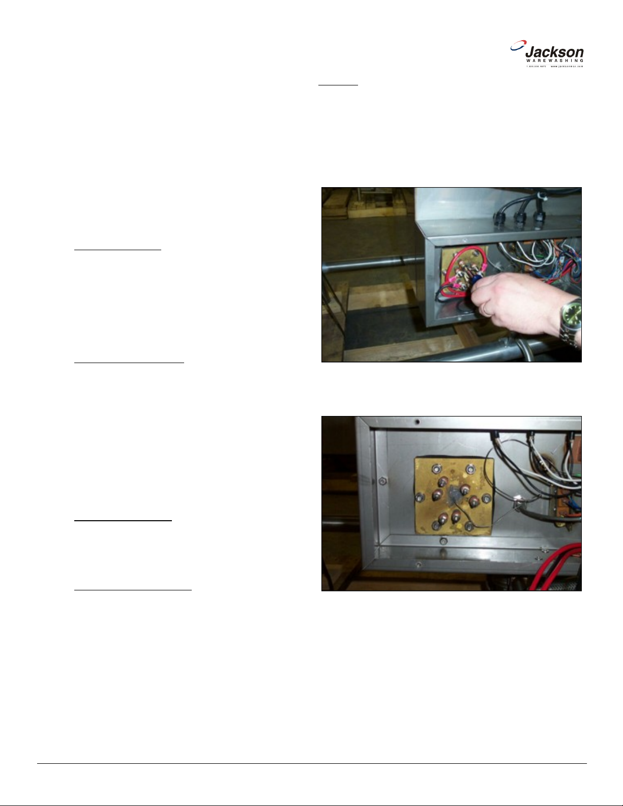
3. Remove the incoming electrical lines from the heater. Set the
5. The thermostat probe needs to be removed from the well inside
the heater. The probe is secured in place with silicone that must be
peeled away prior to attempting to remove it. It is important that
you do not damage the probe during this part of the maintenance
action. If you do, then the thermostat will have to be replaced as
6. Using your hand or needlenose pliers, remove the silicone so
www.jacksonmsc.com
Jackson rack conveyor machines come equipped with
heaters to ensure proper ware washing results. Occasionally,
some of these components may need replacing to maintain opti mum performance.
Jackson offers all of the repair parts necessary for performing this task.
The instructions provided here are for maintenance personnel only. Unauthorized persons should not attempt any of the
steps contained in these instructions.
Warning: many of the instructions and steps within
this document require the use of tools. Only authorized per sonnel should ever perform any maintenance procedure on
the dishmachine!
PREPARATION
1. Power must be secured to the unit at the service breaker. Tag or lock out the service breaker to prevent accidental or
unauthorized energizing of the machine.
2. Ensure that incoming water to the machine is secured
either by use of a shut-off valve or disconnecting the incoming
water line.
3. The unit must be drained completely.
TOOLS REQUIRED
The following tools will be needed to perform this mainte-
nance evolution:
1. 3/8” Nutdriver
2. Ratchet
3. 1/2” Socket
4. 3/8” Socket
5. Phillipshead Screwdriver
6. Needlenose Pliers
7. Torque Wrench
8. Siliconee Sealant
9. Amp Meter
STEPS
1. Remove the front dress panel.
cover and hardware to the side.
hardware to the side.
Removing the power lines.
4. Push the incoming electrical lines out of the way.
TIME REQUIRED
It is estimated that it will take (1) person ninety minutes to
perform this task, not including all of the items indicated in the section entitled “PREPARATION”.
IMPORTANT NOTES
1. Read these instructions thoroughly before attempting
this maintenance task. Become familiar with the parts and what
actions need to be taken. This will save time in the long run!
Heater without power lines attached.
well.
that the thermostat probe may be gently removed.
2
Heater Replacement Instructions
Revision A (10/14/2005)
Page 3

9. Remove the gasket.
10. Before proceeding any further, it is important to verify that the
tub wall is free of any excess debris so that when the new gasket
is applied, there are no gaps that could lead to leaking around the
-
washers and nuts. Tighten the nuts by hand and then use the
torque wrench set to 154 in-lbs to ensure that the nuts are secure.
13. The thermostat probe needs to be placed into the well of the
new heater. Again, use caution when doing this so that the probe
or the capillary tube do not become broken. If this occurs, then the
www.jacksonmsc.com
Removing silicone from thermostat well
7. With the thermostat probe out of the way, use the 1/2” socket
and ratchet to remove the nuts holding the heater to the tub.
Remove all nuts and lockwashers.
Removing the nuts and lockwashers
8. Remove the heater from the tub weldment.
Removing the gasket
heater.
11. Apply the new heater gasket from your service kit.
12. Slide the heater onto the studs and apply by hand the lock
Removing the heater
Heater Replacement Instructions
Revision A (10/14/2005)
Applying the torque wrench to the nuts
thermostat will have to be replaced.
3
Page 4

16. Using the torque wrench or a torque nutdriver (if available)
torge the nuts holding the wires, jumpers and bus bars to 16 in-lbs.
17. Ensuring that all non-essential personnel are clear of the area,
close the drain valve(s) and restore power and water to the unit.
18. Verify that there are no leaks around the heater. If there are,
attempt to tighten it down as the tub will change shape slightly as
19. Use the amp meter to take readings off of the power lines to the
20. Wait until the heater contactor kicks out (meaning that the tub
has reached the appropriate temperature) and place the unit in
DELIME mode by flipping the switch on the back of the control box.
Allow the unit to operate for at least ten minutes to verify that there
-
www.jacksonmsc.com
Putting the thermostat probe in the heater well Three phase wiring
14. Apply silicone to seal the well and hold the thermostat probe in
place.
Applying silicone to the heater well
15. Reattach the incoming power lines to the heater, ensuring that
you wire the heater correctly for either single or three phase operation.
Single phase wiring
Tightening the nuts holding the power lines
Turn the unit on and allow it to fill normally.
it heats up.
heater, verifying the amperage draw to the machine data plate.
are no leaks and that the heater is maintaining the tank tempera
ture.
21. If the unit appears to be operating correctly, return it to AUTO
mode and turn off.
4
Heater Replacement Instructions
Revision A (10/14/2005)
Page 5

Jackson MSC Inc. provides technical support for all of the
dishmachines detailed in this manual. We strongly recommend that
-
port staff. Please have this manual with you when you call so that
our staff can refer you, if necessary, to the proper page. Technical
support is available from 8:00 a.m. to 5:00 p.m. (EST), Monday
through Friday. Technical support is not available on holidays.
Contact technical support toll free at 1-888-800-5672. Please
remember that technical support is available for service personnel
www.jacksonmsc.com
22. Replace the heater box cover.
23. Replace the front dress panel.
AFTER MAINTENANCE ACTIONS
Service perosnnel may want to drain the machine and
allow it to cool down. Secure power to the unit at the service breaker and then verify the torque of all fasteners covered in this instruction.
SPECIAL NOTES
Work performed on Jackson dishmachines by unautho rized or unqualified personnel may void the warranty. Before beginning this or any other maintenance evolution on a unit under warranty, you should contact a certified Jackson technician or Jackson
Technical Service. You can find a list of qualified service agencies
in the back of you unit’s installation manual.
SPECIAL PARTS
Heater Replacement Kit Chart
Model Volts Phase KW Part Number
CONTACT INFORMATION
you refer to this manual before making a call to our technical sup
only.
All 208 1 15 06401-003-10-21
230 1 15 06401-003-10-22
200 3 15 06401-003-10-21
208 3 15 06401-003-10-21
220 3 15 06401-003-10-22
230 3 15 06401-003-10-22
380 3 15 06401-003-10-28
415 3 15 06401-003-10-28
440 3 15 06401-003-10-29
460 3 15 06401-003-10-31
575 3 15 06401-003-10-33
600 3 15 06401-003-10-33
208 1 10 06401-003-12-94
230 1 10 06401-003-12-95
200 3 10 06401-003-12-94
208 3 10 06401-003-12-94
230 3 10 06401-003-12-95
460 3 10 06401-003-12-96
575 3 10 06401-003-12-97
600 3 10 06401-003-12-97
Heater Replacement Instructions
Revision A (10/14/2005)
5
 Loading...