

Page 1

200 SERIES DISHMACHINES
INCLUDING:
200 & 200B (DUAL TEMPERATURE, HOT
WATER SANITIZING, UPRIGHT DOOR
MACHINES)
200LT (CHEMICAL SANITIZING,
UPRIGHT DOOR MACHINE)
SERVICE MANUALSERVICE MANUAL
Visit Jackson on the Internet at:
www.jacksonmsc.com
October 30, 2000 P/N7610-100-45-00 (REV. C)
Page 2

MANUFACTURERS WARRANTY
ONE YEAR LIMITED PARTS & LABOR WARRANTY
ALL NEW JACKSON DISHWASHERS ARE WARRANTED TO THE ORIGINAL PURCHASER TO BE FREE FROM
DEFECTS IN MATERIAL OR WORKMANSHIP, UNDER NORMAL USE AND OPERATION FOR A PERIOD OF (1) ONE
YEAR FROM THE DATE OF PURCHASE, BUT IN NO EVENT TO EXCEED (18) EIGHTEEN MONTHS FROM THE DATE
OF SHIPMENT FROM THE FACTORY.
Jackson MSC agrees under this warranty to repair or replace, at its discretion, any original part which fails under normal use due to faulty
material or workmanship during the warranty period, providing the equipment has been unaltered, and has been properly installed, maintained and operated in accordance with the applicable factory instruction manual furnished with the machine and the failure is reported to
the authorized service agency within the warranty period. This includes the use of factory specified genuine replacement parts, purchased
directly from a Jackson authorized parts distributor or service agency. Use of generic replacement parts may create a hazard and void warranty certification.
The labor to repair or replace such failed part will be paid by Jackson MSC, within the continental United States, Hawaii and Canada, during the warranty period provided a Jackson MSC authorized service agency, or those having prior authorization from the factory, performs
the service. Any repair work by persons other than a Jackson MSC authorized service agency is the sole responsibility of the customer.
Labor coverage is limited to regular hourly rates, overtime premiums and emergency service charges will not be paid by Jackson MSC.
Accessory components not installed by the factory carry a (1) one year parts warranty only. Accessory components such as table limit switches, pressure regulators, pre rinse units, etc. that are shipped with the unit and installed at the site are included. Labor to repair or replace
these components is not covered by Jackson MSC.
This warranty is void if failure is a direct result from shipping, handling, fire, water, accident, misuse, acts of god, attempted repair by unauthorized persons, improper installation, if serial number has been removed or altered, or if unit is used for purpose other than it was originally intended.
TRAVEL LIMITATIONS
Jackson MSC limits warranty travel time to (2) two hours and mileage to (100) one hundred miles. Jackson MSC will not pay for travel time
and mileage that exceeds this, or any fees such as those for air or boat travel without prior authorization.
WARRANTY REGISTRATION CARD
The warranty registration card supplied with the machine must be returned to Jackson MSC within 30 days to validate the warranty.
REPLACEMENT PARTS WARRANTY
Jackson replacement parts are warranted for a period of 90 days from the date of installation or 180 days from the date of shipment from the
factory, which ever occurs first.
PRODUCT CHANGES AND UPDATES
Jackson MSC reserves the right to make changes in design and specification of any equipment as engineering or necessity requires.
THIS IS THE ENTIRE AND ONLY WARRANTY OF JACKSON MSC. JACKSON’S LIABILITY ON ANY CLAIM OF ANY KIND, INCLUDING
NEGLIGENCE, WITH RESPECT TO THE GOODS OR SERVICES COVERED HEREUNDER, SHALL IN NO CASE EXCEED THE PRICE
OF THE GOODS OR SERVICES OR PART THEREOF WHICH GIVES RISE TO THE CLAIM.
THERE ARE NO WARRANTIES, EXPRESSED OR IMPLIED, INCLUDING FOR FITNESS OR MERCHANTABILITY, THAT ARE NOT SET
FORTH HEREIN, OR THAT EXTEND BEYOND THE DURATION HEREOF. UNDER NO CIRCUMSTANCES WILL JACKSON MSC BE
LIABLE FOR ANY LOSS OR DAMAGE, DIRECT OR CONSEQUENTIAL, OR FOR THE DAMAGES IN THE NATURE OF PENALTIES,
ARISING OUT OF THE USE OR INABILITY TO USE ANY OF ITS PRODUCTS.
ITEMS NOT COVERED
This warranty does not cover cleaning or deliming of the unit or any component such as, but not limited to, wash arms, rinse arms or strainers at anytime. Nor does it cover adjustments such as, but not limited to timer cams, thermostats or doors, beyond 30 days from the date
of installation. In addition, the warranty will only cover the replacement of wear items such as curtains, drain balls, door guides or gaskets
during the first 30 days after installation. Also, not covered are conditions caused by the use of incorrect (non-Commercial) grade detergents, incorrect water temperature or pressure, or hard water conditions.
Page 3

TABLE OF CONTENTS
GENERAL PAGE
Specifications .............................................................................................. 1
Nomenclature ............................................................................................. 2
Detail of Data Plate...................................................................................... 3
General Notes.............................................................................................. 4
INSTALLATION
Unpacking...................................................................................................... 5
Plumbing Connections................................................................................... 5
Electrical Connections................................................................................... 5
Installation Checklist...................................................................................... 6
Detergent Control.......................................................................................... 7
OPERATIONAL INSTRUCTIONS
Preparation.................................................................................................... 8
Power Up...................................................................................................... 8
Initial Fill........................................................................................................ 8
Preparing the Dishes.................................................................................... 8
Daily Machine Preparation........................................................................... 8
Washing a Rack of Ware............................................................................. 8
Shut Down and Cleaning............................................................................. 8
TROUBLE SHOOTING SECTION............................................................................ 9
DIMENSIONS............................................................................................................ 12
PHOTOGRAPHS
Main Assembly ........................................................................................... 13
Table Dimensions....................................................................................... 15
Control Box Assembly (200B-1 Phase)...................................................... 16
Control Box Assembly (200B-3 Phase)...................................................... 18
Control Box Assembly (200-200LT1 Phase).............................................. 20
Control Box Assembly (200-200LT3 Phase).............................................. 22
Cantilever Arm Assembly............................................................................ 24
Yoke Assembly............................................................................................ 26
Hood To Tub Assembly............................................................................... 27
Wash Tank Assembly.................................................................................. 28
Lower Wash & Rinse Assembly.................................................................. 29
Upper Wash & Rinse Assembly.................................................................. 30
Incoming Plumbing Assembly 200B............................................................ 31
Incoming Plumbing Assembly 200/200LT.................................................... 33
Solenoid Valve Repair Kit............................................................................ 34
Vacuum Breaker Repair Kit......................................................................... 35
Booster Tank & Motor to Tub Assembly...................................................... 36
REPLACEMENT WIRES & CONDUIT...................................................................... 38
JACKSON MAINTENANCE & REPAIR CENTER NETWORK................................ 42
ELECTRICAL SCHEMATIC...................................................................................... 49
IMPORTANT INFORMATION DATA SHEET............................................................ 50
i
Page 4

SPECIFICATIONS OF THE 200 SERIES
PERFORMANCE/CAPABILITIES
OPERATING CAPACITY (RACKS/HOUR)
RACKS PER HOUR 57
DISHES PER HOUR 1425
GLASSES PER HOUR 1425
OPERATING CYCLE (SECONDS)
WASH TIME 45
RINSE TIME 11
TOTAL CYCLE 58
TANK CAPACITY (GALLONS)
WASH TANK (MINIMUM) 8.0
BOOSTER TANK 3.0
WASH PUMP CAPACITY
GALLONS PER MINUTE 150
AMPERAGE LOAD (12 KW BOOSTER HEATER)
200B UNITS ONLY
VOLTS PHASE AMPS
208 1 71.4
230 1 78.1
208 3 39.6
230 3 43.5
460 3 21.7
AMPERAGE LOAD (14 KW BOOSTER HEATER)
200B UNITS ONLY
VOLTS PHASE AMPS
208 1 78.6
230 1 86.3
208 3 43.8
230 3 48.2
460 3 24.1
AMPERAGE LOAD (200 & 200LT UNITS)
TEMPERATURES
WASH---°F (MINIMUM) 150
RINSE---°F (MINIMUM) 180
WASH---°F, 200 LT (MINIMUM) 130
RINSE---°F, 200 LT (MINIMUM) 130
FRAME DIMENSIONS
WIDTH 25 3/4”
DEPTH 25 5/16”
HEIGHT 56 3/4”
STANDARD TABLE HEIGHT 34”
MAXIMUM INSIDE CLEARANCE 17 1/4”
RACKS
DISH 20” X 20” OPTIONAL
GLASS & SILVER 20” X 20” OPTIONAL
ELECTRICAL REQUIREMENTS
VOLTS PHASE AMPS
208 1 28.1
230 1 30.2
208 3 14.6
230 3 15.8
460 3 7.9
WATER REQUIREMENTS
INLET TEMPERATURE (200) 180°F min
INLET TEMPERATURE (200B)(9 KW) 140°F min
INLET TEMPERATURE (200B)(11 KW) 110°F min
INLET TEMPERATURE (200LT) 140°F min
GALLONS PER HOUR 52.2
GALLONS PER RACK 0.92
WATER LINE SIZE I.P.S. (Minimum) 3/4”
DRAIN LINE SIZE I.P.S. (Minimum) 1-1/2”
FLOW PRESSURE P.S.I. (Optimum) 20
MINIMUM CHLORINE REQUIRED (PPM)(200LT) 50
WASH PUMP MOTOR HP 1
1
Page 5

NOMENCLATURE
This service manual covers three separate models of the 200 line of Jackson dishmachines. A brief description of these models is
included here for your reference.
The 200B is a dual temperature, hot water sanitizing dishmachine. This model employs incoming water at at temperature less than 180'
F (see individual machine data plate for incoming water temperature requirements). The water for rinse is heated using an integral rinse
booster tank to raise the water temperature to the appropriate temperature. The wash tank temperature is maintained through the use
of an internal wash tank heater and from heat transferred from the rinse cycle. The 200B, as stated previously, is a hot water sanitizing dishmachine, in that it uses heat, rather than chemicals, to clean a sanitize ware. The 200B still requires a separate detergent
hookup in order to function correctly.
The 200LT is a chemical sanitizing dishmachine, designed to operate much in the same manner as the 200B. The major difference
between the 200B and the 200LT is that the 200LT does not come with an integral rinse booster tank and must be connected to a third
party chemical feeder system in order to ensure that ware comes clean and is sanitized properly.
The 200 is a dual temperature, hot water sanitizing dishmachine, designed to operate with an incoming water temperature of at least
180' F (see individual machine data plate for incoming water temperature requirements). The 200 does not have an integral rinse booster tank and therefore must be supplied with a higher temperature water than the 200B or 200LT. The 200 must be supplied with a separate detergent dispenser to ensure proper operation.
2
Page 6
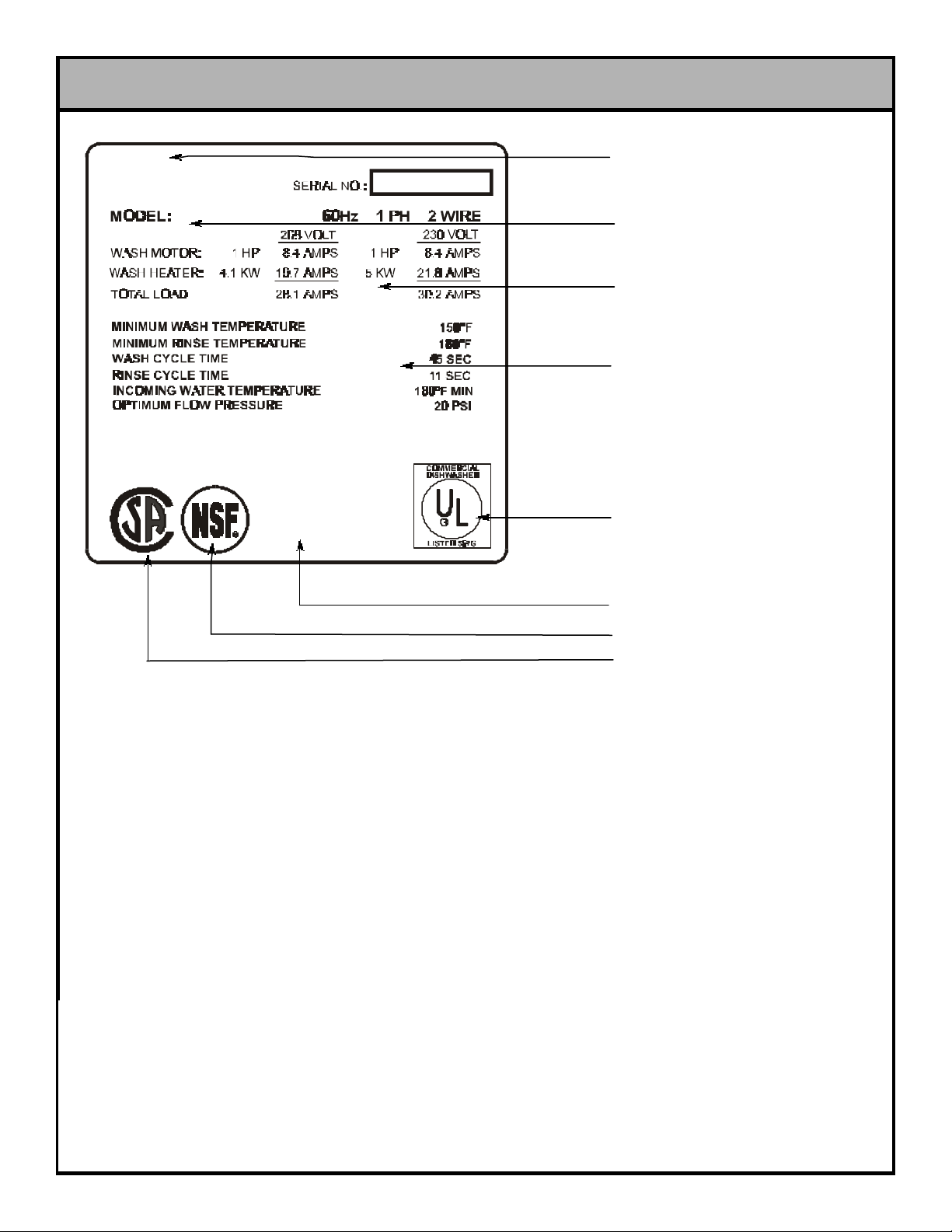
DETAILS OF THE 200 SERIES DATA PLATE
MANUFACTURER’S
LOGO
MODEL DESIGNATION
(I.E. 200)
AMPERAGE LOAD
INFORMATION
MINIMUM OPERATING
PARAMETERS (SEE NOTE #1)
UL LOGO (SEE NOTE #2)
MANUFACTURER’S
ADDRESS INFORMATION
NSF LOGO (SEE NOTE #4)
CSA LOGO (SEE NOTE #3)
The data plate is located (standing before the unit) on the right front corner, directly on the tub. Under no circumstance should the data
plate be removed from the unit. The data plate is essential in identifying the particular characteristics of your machine and is of great
benefit to installers, operators, and maintenance personnel. It is recommended that you copy down the essential information on the
final page in this manual for reference before installation. Do not use the above data plate to represent your dishmachine. The data
plate above is a generic representation used only to show you where to locate information.
3
Page 7

GENERAL NOTES SECTION
Before connecting, operating, or adjusting any of the dishmachines covered in this manual, please carefully read through the entire
manual to familiarize yourself with the machine and its proper operation. This manual contains important operating, safety, and maintenance information concerning your dishmachine. You must follow the instructions and guidelines provided in this manual to ensure
that your warranty remains in effect.
FOR SERVICE PERSONNEL: Jackson MSC Inc. provides technical support for all of the dishmachines detailed in this manual. We
strongly recommend that you refer to this manual before making a call to our technical support staff. Please have this manual with you
when you call so that our staff can refer you, if necessary, to the proper page. Technical support is available from 8:00 a.m. to 5:00 p.m.
(EST), Monday through Friday. Technical support is not available on holidays. Contact technical support toll-free at 1-888-800-5672.
Please remember that technical support is available for service personnel only. Non-service personnel should refer to the list of provided service agencies in this manual for local service support.
NOTES CONCERNING THE 200 SERIES DATA PLATES:
NOTE 1: This area of the data plate denotes the minimum parameters that must be met in order for your dishmachine to operate at the
designed level of efficiency. Not meeting the required parameters can result in substandard performance of the dishmachine. Do not
refer to the data plate example in this manual for the parameters of your machine; instead, refer to the data plate affixed to the machine.
Not every 200 machine operates the same way. If you are unsure of whether or not you are meeting the required minimum parameters, contact your nearest Jackson authorized service agency.
NOTE 2: The UL logo on the data plate indicates that this machine is Listed by Underwriters Laboratories Inc. Representative samples
of this product have been evaluated by UL and meet applicable UL Standards and requirements. Dishmachines are evaluated under
UL Standard 921. For more information concerning the UL logo and UL standards in general, you may write to: Underwriters
Laboratories Inc., 333 Pfingsten Road, Northbrook, IL., 60062; or you may visit their website at www.ul.com.
NOTE 3: The CSA logo on the data plate indicates that this machine has been approved to bear this mark by CSA International Inc.
CSA International evaluates and approves equipment for installation and operation in Canada. Representative samples of this product
have been made available to CSA for inspection to ensure that they meet all applicable Canadian safety standards and regulations.
For more information concerning the CSA mark and CSA standards in general, you may write to: CSA International Inc., 178 Rexdale
Blvd, Rexdale (Toronto), Ontario, Canada, M9W 1R3; or you may visit their website at www.csa-international.org.
NOTE 4: The NSF logo on the data plate indicates that this machine has been approved to be listed under NSF Standard 3 by NSF
International Inc. All of Jackson MSC’s Standard 3 approved dishmachines are listed on the NSF website at www.nsf.org. For more
information concerning NSF International, their testing procedures and their standards in general, you may write to: NSF International
Inc., 789 Dixboro Road, Ann Arbor, MI., 48105.
4
Page 8

INSTALLATION INSTRUCTIONS
VISUAL INSPECTION: Before installing the unit, check the container and machine for damage. A damaged container is an indicator that there may be some damage to the machine. If there is
damage to both the container and machine, do not throw away the
container. The dishmachine has been inspected and packed at
the factory and is expected to arrive to you in new, undamaged
condition. However, rough handling by carriers or others may
result in there being damage to the unit while in transit. If such a
situation occurs, do not return the unit to Jackson; instead, contact
the carrier and ask them to send a representative to the site to
inspect the damage to the unit and to complete an inspection
report. You must contact the carrier within 48 hours of receiving
the machine. Also, contact the dealer through which you purchased the unit.
UNPACKING THE DISHMACHINE: Once the machine has been
removed from the container, ensure that there are no missing
parts from the machine. This may not be obvious at first. If it is discovered that an item is missing, contact Jackson immediately to
have the missing item shipped to you.
LEVEL THE DISHMACHINE: The dishmachine is designed to
operate while being level. This is important to prevent any damage to the machine during operation and to ensure the best
results when washing ware. The unit comes with adjustable bullet
feet, which can be turned using a pair of pliers or by hand if the
unit can be raised safely. Ensure that the unit is level from side to
side and from front to back before making any connections.
In areas where the water pressure fluctuates or is greater than the
recommended pressure, it is suggested that a water pressure regulator be installed. The 200 series models covered in this manual
do not come with water pressure regulators as standard equipment. Please notify Jackson if you have any questions.
Do not confuse static pressure with flow pressure. Static pressure
is the line pressure in a “no flow” condition (all valves and services
are closed). Flow pressure is the pressure in the fill line when the
fill valve is opened during the cycle.
It is also recommended that a shock absorber (not supplied with
the 200 series models) be installed in the incoming water line.
This prevents line hammer (hydraulic shock), induced by the solenoid valve as it operates, from causing damage to the equipment.
PLUMBING CHECK: Slowly turn on the water supply to the
machine after the incoming fill line and the drain line have been
installed. Check for any leaks and repair as required. All leaks
must be repaired prior to placing the machine in operation.
ELECTRICAL POWER CONNECTION: Electrical and grounding
connections must comply with the applicable portions of the
National Electrical Code ANSI/NFPA 70 (latest edition) and/or
other electrical codes.
Disconnect electrical power supply and place a tag at the disconnect switch to indicate that you are working on the circuit.
PLUMBING THE DISHMACHINE: All plumbing connections must
comply with all applicable local, state, and national plumbing
codes. The plumber is responsible for ensuring that the incoming
water line is thoroughly flushed prior to connecting it to any component of the dishmachine. It is necessary to remove all foreign
debris from the water line that may potentially get trapped in the
valves or cause an obstruction. Any valves that are fouled as a
result of foreign matter left in the water line, and any expenses
resulting from this fouling, are not the responsibility of the manufacturer.
CONNECTING THE DRAIN LINE: The drain for the 200 series
models covered in this manual are gravity discharge drains. All
piping from the 1-1/2” MNPT connection on the waste accumulator must be pitched (1/4” per foot) to the floor or sink drain. All piping from the machine to the drain must be a minimum 1-1/2” I.P.S.
and shall not be reduced. There must also be an air gap between
the machine drain line and the floor sink or drain. If a grease trap
is required by code, it should have a flow capacity of 5 gallons per
minute.
WATER SUPPLY CONNECTION: Ensure that you have read the
section entitled “PLUMBING THE DISHMACHINE” above before
proceeding. Install the water supply line (3/4” pipe size minimum)
to the dishmachine line strainer using copper pipe. It is recommended that a water shut-off valve be installed in the water line
between the main supply and the machine to allow access for service. The water supply line is to be capable of 20 PSI “flow” pressure at the recommended temperature indicated on the data plate.
The dishmachine data plate is located on the right side and to the
front of the machine. Refer to the data plate for machine operating requirements, machine voltage, total amperage load and serial number.
To install the incoming power lines, open the control box. This will
require taking a phillipshead screwdriver and removing the four (4)
screws on the sides of the control box. Install 3/4” conduit into the
pre-punched holes in the back of the control box. Route power
wires and connect to power block and grounding lug. Install the
service wires (L1, L2, and L3 (3 phase only)) to the appropriate
terminals as they are marked on the terminal block. Install the
grounding wire into the lug provided. Tighten the connections and
perform the “pull test”. The tightened wires should remain in place
after giving the wires a moderate pull to see if they will come
loose.
It is recommended that “DE-OX” or another similar anti-oxidation
agent be used on all power connections.
VOLTAGE CHECK: Ensure that the power switch is in the OFF
position and apply power to the dishmachine. Check the incoming
power at the terminal block and ensure it corresponds to the voltage listed on the data plate. If not, contact a qualified service
agency to examine the problem. Do not run the dishmachine if the
voltage is too high or too low. Shut off the service breaker and
mark it as being for the dishmachine. Advise all proper personnel
of any problems and of the location of the service breaker.
Replace the control box cover and tighten down the screws.
5
Page 9

INSTALLATION CHECKLIST
CHECK OFF THE FOLLOWING ITEMS AS THEY ARE COMPLETED BEFORE PROCEEDING TO OPERATION OF DISHMACHINE.
Has the dishmachine been checked for concealed/hidden damage?
Has the dishmachine and the surrounding area been properly vented in accordance with all applicable codes?
Has the dishmachine been properly leveled?
Has the drain plumbing been installed with an air gap?
Has the service voltage been checked to ensure that it meets the electrical requirements listed on the dishmachine’s data plate?
Has the dishmachine been properly grounded?
Has the dishmachine circuit breaker/service breaker been sized correctly, given the dishmachine’s load, and has it
been marked clearly and identified to all pertinent personnel?
Has the incoming water supply been flushed for debris?
Is the hot water supply at the minimum temperature as indicated on the dishmachine data plate?
Is the incoming water supply at 20 PSI?
Is the incoming water supply line at 3/4” minimum?
Has the pump intake strainer been installed?
Has the drain stopper been installed?
Have the wash arms been installed?
Have the rinse arms been installed?
6
Page 10

DETERGENT CONTROL
Detergent usage and water hardness are two factors that contribute greatly to how efficient your dishmachine will operate. Using detergent in the proper amount can become, in time, a source of substantial savings. A qualified water treatment specialist can tell you what
is needed for maximum efficiency from your detergent, but you should still know some basics so you’ll understand what they are talking about.
First, you must understand that hard water greatly effects the performance of the dishmachine. Water hardness is the amount of dissolved calcium and magnesium in the water supply. The more dissolved solids in the water, the greater the water hardness. Hard water
works against detergent, thereby causing the amount of detergent required for washing to increase. As you use more detergent, your
costs for operating the dishmachine will increase and the results will decrease. The solids in hard water also may build-up as a scale
on wash and rinse heaters, decreasing their ability to heat water. Water temperature is important in removing soil and sanitizing dishes. If the water cannot get hot enough, your results may not be satisfactory. This is why Jackson recommends that if you have installed
the machine in an area with hard water, that you also install some type of water treatment equipment to help remove the dissolved
solids from the water before it gets to the dishmachine.
Second, hard water may have you adding drying agents to your operating cycle to prevent spotting, when the real problem is deposited solids on your ware. As the water evaporates off of the ware, the solids will be left behind to form the spotting and no amount of drying agent will prevent this. Again, using treated water will undoubtedly reduce the occurrences of this problem.
Third, treated water may not be suitable for use in other areas of your operation. For instance, coffee made with soft water may have
an acid or bitter flavor. It may only be feasible to install a small treatment unit for the water going into the dishmachine itself. Discuss
this option with your qualified water treatment specialist.
Even after the water hardness problems have been solved, there still must be proper training of dishmachine operators in how much
detergent is to be used per cycle. Talk with your water treatment specialist and detergent vendor and come up with a complete training program for operators. Using too much detergent has as detrimental effects as using too little. The proper amount of detergent must
be used for job. It is important to remember that certain menu items may require extra detergent by their nature and personnel need to
be made aware of this. Experience in using the dishmachine under a variety of conditions, along with good training in the operation of
the machine, can go a long way in ensuring your dishmachine operates as efficiently as possible.
Certain dishmachine models require that chemicals be provided for proper operation and sanitization. Some models even require the
installation of third-party chemical feeders to introduce those chemicals to the machine. Jackson does not recommend or endorse any
brand name of chemicals or chemical dispensing equipment. Contact your local chemical distributor for questions concerning these
subjects.
Some dishmachines come equipped with integral solid detergent dispensers. These dispensers are designed to accommodate detergents in a certain sized container. If you have such a unit, remember to explain this to your chemical distributor upon first contacting
them.
As explained before, water temperature is an important factor in ensuring that your dishmachine functions properly. The data plate located on each unit details what the minimum temperatures must be for either the incoming water supply, the wash tank and the rinse tank,
depending on what model of dishmachine you have installed. These temperatures may also be followed by temperatures that Jackson
recommends to ensure the highest performance from you dishmachine. However, if the minimum requirements are not met, the
chances are your dishes will not be clean or sanitized. Remember, a dish can look clean, but it may not be sanitized. Instruct your dishmachine operators to observe the required temperatures and to report when they fall below the minimum allowed. A loss of temperature can indicate a much larger problem such as a failed heater or it could also indicate that the hot water heater for your operation is
not up to capacity and a larger one may need to be installed.
There are several factors to consider when installing your dishmachine to ensure that you get the best possible results from it and that
it operates at peak efficiency for many years. Discuss your concerns with your local chemical distributor and water treatment specialist before there is a problem.
7
Page 11

OPERATION INSTRUCTIONS
PREPARATION: Before proceeding with the start-up of the unit,
verify the following:
1. The pan strainers and pump suction strainer are in
place and are clean.
2. The overflow tube and o-ring are installed.
3. That the wash and rinse arm assemblies are secured
into place and that their endcaps are tight. The wash
and rinse arm assemblies should rotate freely.
POWER UP: To energize the unit, turn on the power at the service
breaker. The voltage should have been previously verified as
being correct. If not, the voltage will have to be verified.
NOTE: UNLESS OTHERWISE SPECIFIED IN THESE
INSTRUCTION, ENSURE THAT THE MANUAL MODE SWITCH
IS IN THE “OFF” POSITION BEFORE PROCEEDING WITH
ANY OF THE FOLLOWING STEPS.
FILLING THE WASH TUB: Place the power switch into the ON
position. Then place the cycle mode switch in the AUTO position.
The machine should fill automatically and shut off when the appropriate level is reached (just below the pan strainer). Verify that the
drain stopper is preventing the wash tub water from pouring out
excessively. There may be some slight leakage from the drain
hole. Verify that there are no other leaks on the unit before proceeding any further. The wash tub must be completely filled before
operating the wash pump to prevent damage to the component.
Once the wash tub is filled, the unit is ready for operation.
WARE PREPARATION: Proper preparation of ware will help
ensure good results and less re-washes. If not done properly,
ware may not come out clean and the efficiency of the dishmachine will be reduced. It is important to remember that a dishmachine is not a garbage disposal and that simply throwing
unscraped dishes into the machine simply defeats the purpose
altogether of washing the ware. Scraps should be removed from
ware prior to being loaded into a rack. Pre-rinsing and pre-soaking are good ideas, especially for silverware and casserole dishes. Place cups and glasses upside down in racks so that they do
not hold water during the cycle. The dishmachine is meant not
only to clean, but to sanitize as well, to destroy all of the bacteria
that could be harmful to human beings. In order to do this, ware
must be properly prepared prior to being placed in the machine.
Repeat this two more times. The unit should now be ready to proceed with the washing of ware.
WASHING A RACK OF WARE: To wash a rack, open the doors
completely (being careful for hot water that may drip from the
doors) and slide the rack into the unit. Close the doors and the
unit will start automatically. Once the cycle is completed, open the
door (again watching for the dripping hot water) and remove the
rack of clean ware. Replace with a rack of soiled ware and close
the doors. The process will then repeat itself.
OPERATIONAL INSPECTION: Based upon usage, the pan
strainer may become clogged with soil and debris as the workday
progresses. Operators should regularly inspect the pan strainer to
ensure it has not become clogged. If the strainer does, it will
reduce the washing capability of the machine. Instruct operators
to clean out the pan strainer at regular intervals or as required by
work load.
SHUTDOWN AND CLEANING: At the end of the workday, close
the doors. When the unit completes the cycle, turn the power
switch to the OFF position and open the doors. Manually remove
the drain stopper from the tub and allow the tub to drain (NOTE:
the wash tank water will be hot so caution is advised). Once the
wash tub is drained, remove the pan strainers and the pump suction strainer. Remove soil and debris from the strainer and set to
the side. Remove the wash and rinse arm assemblies from their
manifolds. Remove the endcaps and flush the arms with water.
Use a brush to clean out the inside of the arms. If the nozzles
appear to be clogged, use a toothpick to remove the obstruction.
Wipe the inside of the unit out, removing all soil and scraps.
Reassemble the wash and rinse arm assemblies and replace.
NOTE: When replacing the arms, do not use any tools to do so,
the assemblies should secure by hand. Reinstall the strainers and
close the doors.
DAILY MACHINE PREPARATION: Refer to the section entitled
“PREPARATION” at the top of this page and follow the instructions
there. Afterwards, check that all of the chemical levels are correct
and/or that there is plenty of detergent available for the expected
workload.
WARM-UP CYCLES: For a typical daily start-up, it is probably a
good idea to run the machine through 3 cycles to ensure that all
of the cold water is out of the system and to verify that the unit is
operating correctly. To cycle the machine, ensure that the power
is on, the cycle mode switch is in AUTO and that the tub has filled
to the correct level. Lift the doors and the cycle light will illuminate.
When the light goes out, close the doors, the unit will start, run
through the cycle, and shut off automatically.
8
Page 12

TROUBLESHOOTING SECTION
WARNING: Inspection, testing and repair of electrical equipment should only be performed by a qualified service techni-
cian. Many of the tests require that the unit have power to it and live electrical components be exposed. USE
EXTREME CAUTION WHEN TESTING THE MACHINE.
Symptom
Dishmachine will not run. No power to the
unit.
Dishmachine will not run. There is power to
the unit.
Possible Cause Action
Service breaker tripped. Reset breaker. If breaker trips again,
immediately contact an electrician.
Incoming power lines not installed in control
box.
Incoming power lines connections not
tightened.
Door switch shorted out or is disconnected. Check to ensure door switch wires are
Faulty "ON/OFF" switch Ensure switch is wired properly.
Install power lines.
Tighten connections.
connected correctly. If so, replace door
switch.
If so, replace switch.
Machine runs, but there is no water.
Dishmachine fills continuously, even with no
power to the machine.
Solid state timer, faulty. Check wiring, replace if necessary.
No water supply to machine. Check to ensure that all water valves are
open and that water is being supplied to the
machine at 20 PSI.
Incoming water supply solenoid not
operating.
Incoming water supply solenoid not
operating. (Stuck open)
Check to ensure that valve is wired
correctly. If so, replace valve.
Check to ensure that valve is wired
correctly. If so, replace valve.
9
Page 13

TROUBLESHOOTING SECTION (CONTINUED)
WARNING: Inspection, testing and repair of electrical equipment should only be performed by a qualified service techni-
cian. Many of the tests require that the unit have power to it and live electrical components be exposed. USE
EXTREME CAUTION WHEN TESTING THE MACHINE.
Symptom
Dishmachine fills continuously, only when
the power is on.
Dishmachine runs with the door open.
Possible Cause Action
Incoming water supply solenoid not
operating properly.
Faulty solid state timer. Check wiring, replace if necessary.
Shorted out ON/FILL switch. Check the voltage across the switch. If the
Shorted/defective liquid level control board
or probe.
Door switch shorted out/wired incorrectly. Check the wiring of the door switch, if
Check to ensure that valve is wired
correctly. If so, replace valve.
voltage is incorrect, replace the switch.
Check voltage going to each component
and ensure they are wired correctly. If
satisfactory, replace the defective part.
correct, replace the door switch.
Low wash water pressure.
Faulty wash relay (wash relay welded
closed).
Water level is too low. Check to ensure that the drain stopper is in
Pump intake strainer is clogged. Remove and clean strainer.
Wash arms (nozzles) are clogged. Remove wash arms and clean.
Turn machine off, if wash relay doesn't
release, replace contactor.
and has an O-ring. Check to ensure that the
LLC board and probe are functioning
properly.
10
Page 14

TROUBLESHOOTING SECTION (CONTINUED)
WARNING: Inspection, testing and repair of electrical equipment should only be performed by a qualified service techni
cian. Many of the tests require that the unit have power to it and live electrical components be exposed. USE
EXTREME CAUTION WHEN TESTING THE MACHINE.
Symptom
Low wash water pressure.
Water temperature is less than required.
Possible Cause Action
Pump impeller worn or broken. Replace pump.
Low incoming water temperature. Compare to data plate.
No power to heater. Check wiring, replace if necessary.
Thermostat out of adjustment. Adjust or replace thermostat as required.
11
Page 15
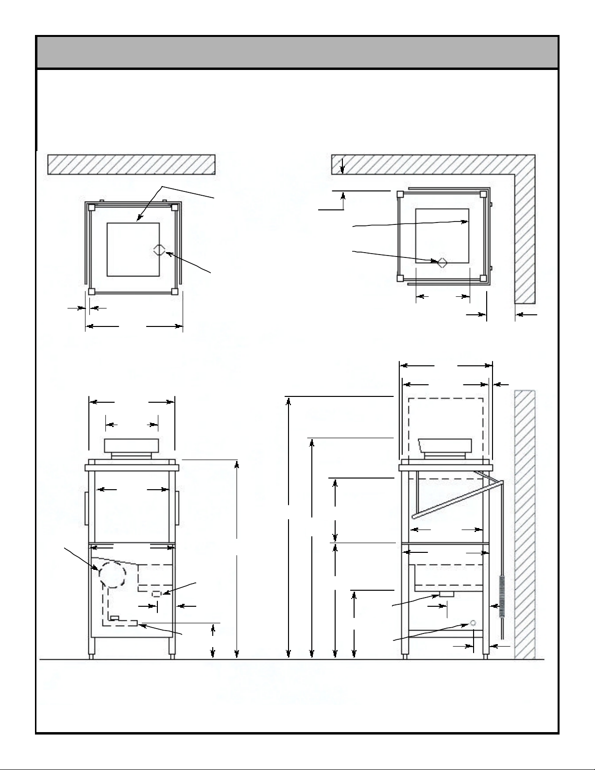
LEGEND:
A- Drain 1 1/2” I.P.S.
B- Water inlet 3/4” I.P.S.
C- Electrical connection
D- Standard wall clearance, with dish table 4”
E- Model 200B booster tank location
C
A
3 1/2”
32”
DIMENSIONS
D
TOP VIEW
CORNER CONVERSION
C
A
16 1/8”
D
E
TOP VIEW
FRONT
25 1/4”
15 1/2”
21 1/8”
25 1/2”
B
A
2 7/8”
10 3/4”
56 3/4”
75 1/2”
64”
17 3/4”
34”
15 1/2”
A
B
30”
25 1/6”
21 1/8”
25 5/16”
13 1/2”
2 7/8”
3 3/4”
FRONT VIEW RIGHT SIDE VIEW
12
Page 16
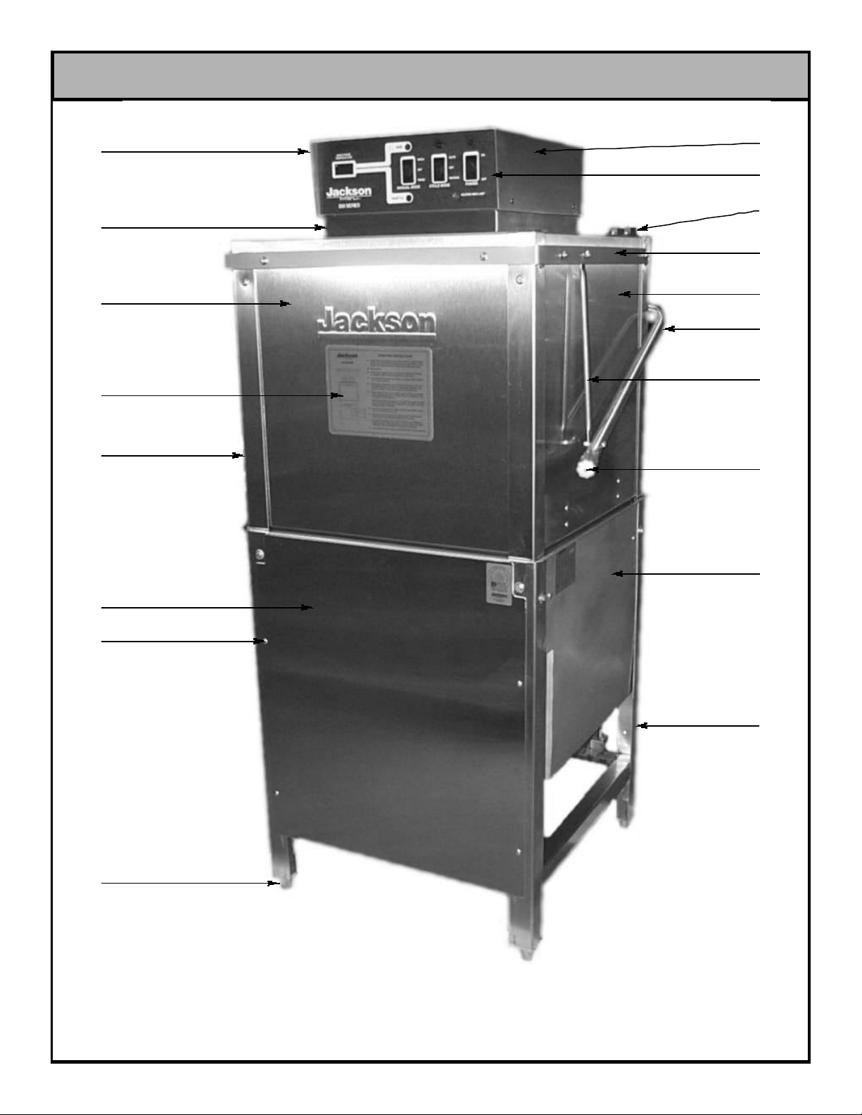
MAIN ASSEMBLY
01
02
03
04
05
09
10
11
12
13
14
15
16
06
07
08
17
18
13
Page 17

MAIN ASSEMBLY (CONTINUED)
ITEM QTY DESCRIPTION MFG NO.
01 1 Control Box 5700-001-26-44
02 1 Control Box Platform 5700-001-26-89
03 1 Door, Front 5700-001-25-72
04 1 Decal, Operation 200 9905-101-11-12
05 1 Door, Left Side 5700-001-25-73
06 1 Panel, Front 5700-001-25-80
07 4 Screw, 10-32 X 3/8" Long Truss 5305-173-12-00
08 4 Bullet Feet 5340-108-02-06
09 1 Cover, Control Box 5700-001-22-09
10 1 Decal, Control Box 9905-101-00-00
11 1 Magnetic Door Switch Assembly 5930-111-51-22
12 1 Door Connector Wrap 5700-001-22-73
13 1 Door, Right Side 5700-001-25-74
14 1 Cantilever Arm Assembly 5700-001-25-75
15 2 Connector, Cantilever Arm 5700-001-25-42
16 2 Grips, Handle 5340-106-07-00
17 1 Tub Weldment 5700-001-25-48
18 1 Frame Weldment 5700-001-25-46
14
Page 18

TABLE DIMENSIONS
CORNER INSTALLATION
TABLE DIMENSIONS
2 1/4”
MIN.
4”
20 1/2”
OPENING
25 1/4”
3/4”
20 1/2”
1 1/2” ROLL
TABLE DIMENSIONS
CONNECTION TO DISHMACHINE
TABLE DIMENSIONS
STRAIGHT THROUGH INSTALLATION
25 1/4”
15
Page 19

200B CONTROL BOX ASSEMBLY (208-230 VOLT 1 PHASE)
03
01
04
02
05
06
07
09
08
11
10
12
13
29
27
28
26
25
24
23
22
21
20
18
14 15 16 17
03 30 09 11 13
31 32 33 34 08 10 35
19
12
16
Page 20

200B CONTROL BOX ASSEMBLY (208-230 VOLT 1 PHASE) (CONTINUED)
ITEM QTY DESCRIPTION MFG NO.
01 1 Timer, Solid State 5945-307-07-93
02 1 Liq. Level Control, 2 Probe, 4 SEC 6680-200-01-93
03 1 Thermometer, Led w/ 21" & 89" Probe 6685-400-04-00
04 2 Locknut, 10-24 S/S Hex w/ Nylon Insert 5310-373-01-00
05 1 Platform, Back Control Box 5700-001-26-60
06 2 Screw, 10-32 X 3/8" Long Truss 5305-173-12-00
07 1 Din Rail, 9-11/16" Long 5700-001-26-97
08 1 Switch, SPDT 3 Position, WASH-OFF-RINSE 5930-302-03-41
09 1 Light, Amber Indicator 28 VAC 5945-504-02-90
10 1 Switch, SPDT 3 Position, AUTO-OFF-MANUAL 5930-302-01-41
11 1 Light, Green Indicator 28 VAC 5945-504-04-90
12 1 Switch, SPDT 2 Position, ON-OFF 5930-302-02-41
13 1 Light, Red Indicator 28 VAC 5945-504-01-90
14 1 Relay, Wash Motor, 208-460V, 1PH & 3 PH 5945-109-03-09
15 1 Relay, Wash Heater, 208-230V, 1 PH 5945-109-02-09
16 1 Relay, Rinse Heater, 208-230/380/460V 5945-109-01-09
17 4 Tricnut, 10-32 5340-118-05-00
18 1 Control Box Weldment w/ Tric-nuts 5700-001-26-44
19 1 WireLug 5940-200-76-00
20 1 Decal, L1, L2, L3, 9905-101-12-66
21 1 Decals, Copper Conductors 9905-011-47-35
22 1 Block, 3 Pole Power Distirbution 5945-603-01-66
23 2 Screw, 10-32 X 7/8" Fillister Head 5305-973-04-00
24 2 Fitting, 3/4" Straight Xtraflex 5975-205-46-44
25 4 Screw, 10-32 X 7/8" Fillister Head 5305-973-04-00
26 1 Relay, 24 VAC Coil 5945-301-07-40
27 1 Holder, Fuse #350 330 5920-401-03-14
28 1 Transformer, 60VA, 208/24V Class 5950-400-01-35
29 2 Screw, 10-32 X 3/8" Long Truss 5305-173-12-00
30 1 Decal, Control Box 9905-101-00-00
31 1 Cover, Control Box 5700-001-22-09
32 1 Spacer, Control Box 9515-800-94-00
33 1 Platform, w/Tricnut 5700-001-26-89
34 1 Light, Blue Indicator 28 VAC 5945-504-05-90
35 1 Light, Clear Indicator 28 VAC 5945-504-03-90
17
Page 21

200B CONTROL BOX ASSEMBLY (208-230/460 VOLT 3 PHASE)
30
01
02
03
04
05
06
07
08
09
10
11
12
13
29
28
27
26
25
24
23
22
21
20
19
14 15 16 17 18
03 31 09 11 13
32 33 34 35 08 10 36
12
18
Page 22

200B CONTROL BOX ASSEMBLY (208-230/460 VOLT 3 PHASE) (CONTINUED)
ITEM QTY DESCRIPTION MFG NO.
01 1 Timer, Solid State 5945-307-07-93
02 1 Liq. Level Control, 2 Probe, 4 SEC 6680-200-01-93
03 1 Thermometer, Led w/ 21" & 89" Probe 6685-400-04-00
04 2 Locknut, 10-24 S/S Hex w/ Nylon Insert 5310-373-01-00
05 1 Platform, Back Control Box 5700-001-26-60
06 2 Screw, 10-32 X 3/8" Long Truss 5305-173-12-00
07 1 Din Rail, 9-11/16" Long 5700-001-26-97
08 1 Switch, SPDT 3 Position, WASH-OFF-RINSE 5930-302-03-41
09 1 Light, Amber Indicator 28 VAC 5945-504-02-90
10 1 Switch, SPDT 3 Position, AUTO-OFF-MANUAL 5930-302-01-41
11 1 Light, Green Indicator 28 VAC 5945-504-04-90
12 1 Switch, SPDT 2 Position, ON-OFF 5930-302-02-41
13 1 Light, Red Indicator 28 VAC 5945-504-01-90
14 1 Overload, 2.5-4 AMP Range 5945-111-68-41
14 1 Overload, 460V, 3 PH 5945-304-02-09
15 1 Relay, Wash Motor, 208-460V, 1PH & 3 PH 5945-109-03-09
16 1 Relay, Wash Heater, 208-230V, 1 PH 5945-109-02-09
17 1 Relay, Rinse Heater, 208-230/380/460V 5945-109-01-09
18 4 Tricnut, 10-32 5340-118-05-00
19 1 Control Box Weldment w/ Tric-nuts 5700-001-26-44
20 1 WireLug 5940-200-76-00
21 1 Decal, L1, L2, L3, 9905-101-12-66
22 1 Decals, Copper Conductors 9905-011-47-35
23 1 Block, 3 Pole Power Distirbution 5945-603-01-66
24 2 Screw, 10-32 X 7/8" Fillister Head 5305-973-04-00
25 2 Fitting, 3/4" Straight Xtraflex 5975-205-46-44
26 4 Screw, 10-32 X 7/8" Fillister Head 5305-973-04-00
27 1 Relay, 24 VAC Coil 5945-301-07-40
28 1 Holder, Fuse #350 330 5920-401-03-14
29 1 Transformer, 60VA, 208/240V Class 5950-400-01-35
29 1 Transformer, 60VA, 460V 5950-400-02-35
30 2 Screw, 10-32 X 3/8" Long Truss 5305-173-12-00
31 1 Decal, Control Box 9905-101-00-00
32 1 Cover, Control Box 5700-001-22-09
33 1 Spacer, Control Box 9515-800-94-00
34 1 Platform, w/Tricnut 5700-001-26-89
35 1 Light, Blue Indicator 28 VAC 5945-504-05-90
36 1 Light, Clear Indicator 28 VAC 5945-504-03-90
19
Page 23

200/200LT CONTROL BOX ASSEMBLY (1 PHASE)
01
03
02
04
05
06
07
09
08
10
11
28
27
26
25
24
23
22
21
20
19
17
12
13
14 15 16
03 29 09 11 13
18
12
30 31 32 33 08 10 34
20
Page 24

200/200LT CONTROL BOX ASSEMBLY (1 PHASE) (CONTINUED)
ITEM QTY DESCRIPTION MFG NO.
01 1 Timer, Solid State 5945-307-07-93
02 1 Liq. Level Control, 2 Probe, 4 SEC 6680-200-01-93
03 1 Thermometer, Led w/ 21" & 89" Probe 6685-400-04-00
04 2 Locknut, 10-24 S/S Hex w/ Nylon Insert 5310-373-01-00
05 1 Platform, Back Control Box 5700-001-26-60
06 2 Screw, 10-32 X 3/8" Long Truss 5305-173-12-00
07 1 Din Rail, 9-11/16" Long 5700-001-26-97
08 1 Switch, SPDT 3 Position, WASH-OFF-RINSE 5930-302-03-41
09 1 Light, Amber Indicator 28 VAC 5945-504-02-90
10 1 Switch, SPDT 3 Position, AUTO-OFF-MANUAL 5930-302-01-41
11 1 Light, Green Indicator 28 VAC 5945-504-04-90
12 1 Switch, SPDT 2 Position, ON-OFF 5930-302-02-41
13 1 Light, Red Indicator 28 VAC 5945-504-01-90
14 1 Relay, Wash Motor, 208-460V, 1PH & 3 PH 5945-109-03-09
15 1 Relay, Wash Heater, 208-230V, 1 PH 5945-109-02-09
16 4 Tricnut, 10-32 5340-118-05-00
17 1 Control Box Weldment w/ Tric-nuts 5700-001-26-44
18 1 WireLug 5940-200-76-00
19 1 Decal, L1, L2, L3, 9905-101-12-66
20 1 Decals, Copper Conductors 9905-011-47-35
21 1 Block, 3 Pole Power Distirbution 5945-603-01-66
22 2 Screw, 10-32 X 7/8" Fillister Head 5305-973-04-00
23 2 Fitting, 3/4" Straight Xtraflex 5975-205-46-44
24 4 Screw, 10-32 X 7/8" Fillister Head 5305-973-04-00
25 1 Relay, 24 VAC Coil 5945-301-07-40
26 1 Holder, Fuse #350 330 5920-401-03-14
27 1 Transformer, 60VA, 208/24V Class 5950-400-01-35
28 2 Screw, 10-32 X 3/8" Long Truss 5305-173-12-00
29 1 Decal, Control Box 9905-101-00-00
30 1 Cover, Control Box 5700-001-22-09
31 1 Spacer, Control Box 9515-800-94-00
32 1 Platform, w/Tricnut 5700-001-26-89
33 1 Light, Blue Indicator 28 VAC 5945-504-05-90
34 1 Light, Clear Indicator 28 VAC 5945-504-03-90
21
Page 25

200/200LT CONTROL BOX ASSEMBLY (208-230/460 VOLT 3 PHASE)
03
01
02
04
05
06
07
09
08
11
10
13
12
29
28
27
26
25
24
23
22
21
20
18
14 15 16 17
03 30 09 11 13
31 32 33 34 08 10 35
19
12
22
Page 26

200/200LT CONTROL BOX ASSEMBLY (208-230/460 VOLT 3 PHASE) (CONT)
ITEM QTY DESCRIPTION MFG NO.
01 1 Timer, Solid State 5945-307-07-93
02 1 Liq. Level Control, 2 Probe, 4 SEC 6680-200-01-93
03 1 Thermometer, Led w/ 21" & 89" Probe 6685-400-04-00
04 2 Locknut, 10-24 S/S Hex w/ Nylon Insert 5310-373-01-00
05 1 Platform, Back Control Box 5700-001-26-60
06 2 Screw, 10-32 X 3/8" Long Truss 5305-173-12-00
07 1 Din Rail, 9-11/16" Long 5700-001-26-97
08 1 Switch, SPDT 3 Position, WASH-OFF-RINSE 5930-302-03-41
09 1 Light, Amber Indicator 28 VAC 5945-504-02-90
10 1 Switch, SPDT 3 Position, AUTO-OFF-MANUAL 5930-302-01-41
11 1 Light, Green Indicator 28 VAC 5945-504-04-90
12 1 Switch, SPDT 2 Position, ON-OFF 5930-302-02-41
13 1 Light, Red Indicator 28 VAC 5945-504-01-90
14 1 Overload, 2.5-4 AMP Range 5945-111-68-41
14 1 Overload, 460V, 3PH 5945-304-02-09
15 1 Relay, Wash Motor, 208-460V, 1PH & 3 PH 5945-109-03-09
16 1 Relay, Wash Heater, 208-230V, 1 PH 5945-109-02-09
17 4 Tricnut, 10-32 5340-118-05-00
18 1 Control Box Weldment w/ Tric-nuts 5700-001-26-44
19 1 WireLug 5940-200-76-00
20 1 Decal, L1, L2, L3, 9905-101-12-66
21 1 Decals, Copper Conductors 9905-011-47-35
22 1 Block, 3 Pole Power Distirbution 5945-603-01-66
23 2 Screw, 10-32 X 7/8" Fillister Head 5305-973-04-00
24 2 Fitting, 3/4" Straight Xtraflex 5975-205-46-44
25 4 Screw, 10-32 X 7/8" Fillister Head 5305-973-04-00
26 1 Relay, 24 VAC Coil 5945-301-07-40
27 1 Holder, Fuse #350 330 5920-401-03-14
28 1 Transformer, 60VA, 208/24V Class 5950-400-01-35
28 1 Transformer, 60VA, 460V Class 5950-400-02-35
29 2 Screw, 10-32 X 3/8" Long Truss 5305-173-12-00
30 1 Decal, Control Box 9905-101-00-00
31 1 Cover, Control Box 5700-001-22-09
32 1 Spacer, Control Box 9515-800-94-00
33 1 Platform, w/Tricnut 5700-001-26-89
34 1 Light, Blue Indicator 28 VAC 5945-504-05-90
35 1 Light, Clear Indicator 28 VAC 5945-504-03-90
23
Page 27

CANTILEVER ARM ASSEMBLY
01
02-SEE YOKE
ASSEMBLY
PAGE
03
04
01
05
09
06
07
08
10
09
11
12
09
13
14
15
24
16
17
17
Page 28

CANTILEVER ARM ASSEMBLY (CONTINUED)
ITEM QTY DESCRIPTION MFG NO.
01 4 Locknut, 1/4"- 20 S/S Hex w/ Nylon Insert 5310-374-01-00
02 2 Yoke Assembly 5700-000-75-78
03 6 Wear Button, 1/2" D. UHMW 5700-011-88-01
04 2 Cantilever Arm Support Brkt. 5700-031-88-00
05 2 Handle Grips 5340-106-07-00
06 1 Cantilever Arm 5700-001-21-00
07 2 Spring Rod 5700-001-28-18
08 2 Springs 5340-109-02-00
09 3 Washer, 1/4" ID S/S 5311-174-01-00
10 2 Cantilever Arm Connector 5700-001-25-42
11 2 Locknut, 1/4"- 20 S/S Low Profile w/ Nylon Insert 5310-374-02-00
12 2 Bolt, Hex Head 1/4"- 20 X 3/4" Long 5305-274-04-00
13 2 Sleeve, Lever & Wrap 5700-001-25-41
14 2 Sleeve, Cantilever Arm 5700-000-85-69
15 2 Screw, 1/4"- 20 X 1-1/2" Long Hex Head 5305-274-23-00
16 2 Bolt, Hanger Eye, 3/8-16 5306-956-05-00
17 4 Nut, 3/8"- 16 S/S Hex Head 5310-276-01-00
25
Page 29

YOKE ASSEMBLY
01 02 03 04 05
06
ITEM QTY DESCRIPTION MFG NO.
01 1 Cotter Pin, 3/32 X 3/4" 5315-207-01-00
02 1 Yoke, Finished 5700-000-75-78
03 1 Bushing 3120-100-03-00
04 2 Washer, Nylon 5311-369-03-00
05 1 Clevis Pin 5315-700-01-00
06 1 Nut, Center Lock 3/8"- 16 S/S 5310-256-04-00
26
Page 30

01
02
03
HOOD TO TUB ASSEMBLY
06
07
08
09
04-NOT
SHOWN
05
ITEM QTY DESCRIPTION MFG NO.
01 1 Hood-Top, Back, & Side Rail 5700-001-23-22
02 4 Hood Suport 5700-001-20-83
03 2 Front Door Rail 5700-001-20-82
04 6 Spacer, Bottom Corner 5700-001-23-05
05 1 Tub Weldment 5700-001-25-48
06 12 Bolt, 1/4-20 X 1-1/8" S/S Hex Head 5305-274-21-00
07 22 1/4" S/S Washer 5311-174-01-00
08 2 Bolt, 1/4-20 X 5/8" S/S Hex Head 5305-275-24-00
09 2 Cantilever Arm Support Bracket 5700-031-88-00
10 6 Screw, w/Rubber Washer 1/4"- 20 X 1/2" Long 5305-974-01-00
11 22 1/4-20 S/S Hex Nut w/Nylon Insert 5310-374-01-00
12 2 Bolt, 1/4"- 20 X 3/4" Hex Head 5305-274-01-00
27
10
11
12
08
06
Page 31

WASH TANK ASSEMBLY
Probe, & 89
g
01 02 01 03 04 05 06 07 08 1009
ITEM QTY DESCRIPTION MFG NO.
01 2 Water Level Probe 3/8" NPT 6680-200-02-68
02 1 Thermometer, Led w/21
03 1
04 1 Wash Thermostat w/Loxit Ffitting 150
05 2 Locknut, 1/4"- 20 S/S w/Nylon Insert 5310-374-01-00
06 1 Drain Tube Assembly 5700-001-25-69
07 1 Suction Strainer Bracket 5700-001-22-24
08 1 Suction Strainer 5700-001-22-23
09 1 Heater, Wash 240V 5300W FLG. Immersion 4540-100-02-15
10 2 Plu
Hi Limit Thermostat w/ Loxit Fitting 220
, Bulk Head 4730-609-05-00
' '
' '
Probe 6685-400-04-00
°°
F Fixed
°°
F Adjustable 5930-510-02-79
5930-510-01-79
28
Page 32

LOWER WASH & RINSE ARM ASSEMBLY
01 02 03 04 05 06 07 08 09 10 11
ITEM QTY DESCRIPTION MFG NO.
01 1 Top Wash & Rinse Manifold Assembly 5700-001-25-52
02 1 Track Assembly 5700-001-22-16
03 2 Manifold Gasket 5330-500-18-00
04 1 Wash Arm Assembly 5700-021-42-00
05 1 Bottom Wash & Rinse Manifold Weld Assembly 5700-001-25-53
06 1 Wash Spindle, Machined 5700-021-41-81
07 1 Rinse Spindle, Machined 5700-031-41-89
08 1 Wash Head Cap 5700-021-41-92
09 2 Plug, Bulk Head 4730-609-05-00
10 1 Rinse Arm Assembly 5700-021-41-98
11 2 Strainer Weldment 5700-001-22-25
29
Page 33

UPPER WASH & RINSE ARM ASSEMBLY
p
01 02 03 04 05 06 07 08 09 10
ITEM QTY DESCRIPTION MFG NO.
01 1 Top Wash & Rinse Manifold Weld Assembly 5700-001-25-52
02 1 Bottom Wash & Rinse Manifold Weld Assembly 5700-001-25-53
03 2 Clamp, Hose Spring Clamp 1" Nom. 4730-719-02-37
04 1 Rinse Manifold Hose 5700-001-26-50
05 1 Rinse Arm Assembly 5700-021-41-98
06 1 Wash Head Cap 5700-021-41-92
07 1 Rinse Spindle, Machined 5700-031-41-89
08 1 Wash Arm Assembly 5700-021-42-00
09 1 Wash Spindle, Machined 5700-021-41-81
10 4 Door Sto
5700-021-38-88
30
Page 34

200B INCOMING PLUMBING
01
02
03
04
05
06
07 08 09
10
31
11 04 13 14 15 16 05 17 1612
Page 35

200B INCOMING PLUMBING (CONTINUED)
ITEM QTY DESCRIPTION MFG NO.
01 3 Plug, 1/8" N.P.T. Brass 4730-209-07-37
02 1 Vacum Breaker, 3/4 (Alternate) 4820-300-08-00
03 1 Rinse Injector Assembly 5700-001-25-78
04 4 Nipple, Close Brass 3/4" 4730-207-34-00
05 2 Union, 3/4 Brass 4730-212-05-00
06 1 Tubing, Copper 3/4" X 29.375 Long 5700-011-82-29
07 2 Rinse Injector Gasket 5330-500-19-00
08 1 Booster, Rinse Tank Weldment 5700-001-22-02
''
09 1 Elbow, 3/4 90
10 1 Thermometer, Led w/21 Probe, 4 SEC TD 6680-200-01-93
11 1 Strainer, Y - 3/4" Watts 4730-717-02-06
12 1 Ball Valve, Test Cock 1/4" Bronze 4810-011-72-67
13 1 Tee, Brass 3/4" X 3/4" X 1/4" 4730-211-04-00
14 1 Guage, 0-100 PSI 2 Pressure 6685-111-59-66
15 1 Solenoid Valve, 3/4" 24 Volt 4820-100-01-40
16 2 Elbow, 3/4" Street Brass 4730-206-04-34
17 1 Nipple, 3/4" Brass X 6" Long 5700-001-26-74
Brass 4730-206-13-00
32
Page 36

200/200LT INCOMING PLUMBING
The plumbing of the 200 NO BOOSTER has the same
parts as the 200 BOOSTER plumbing except the parts
indicated below, also minus the parts of the booster tank
assembly.
5700-011-65-25
Copper Tube, 3/4” X 46-3/8” long
33
Page 37

SOLENOID VALVE REPAIR KITS (3/4”, 24V)
ITEM QTY DESCRIPTION MFG. NO.
01 1 Coil, 24 Volt 4810-100-06-18
02 1 Spring 4810-200-04-18
03 1 Plunger 4810-200-04-18
04 1 O-Ring 4810-100-10-18
05 1 Diaphram Retainer 4810-100-10-18
Order the entire solenoid valve using part number 4810-100-03-18.
Screw
Data Plate
01
Valve Bonnet
03
Diaphragm Retainer
Diaphragm Retainer
02
04
05
Valve Body
Mesh Screen
34
Page 38

CAP
CAP RETAINER
VACUUM BREAKER REPAIR KIT (3/4” NPT)
CAP SCREW
DATA PLATE
COMPONENTS OF REPAIR KIT
4820-001-60-57
O-RING
PLUNGER
BODY
Order the entire assembly using part number 4820-300-08-00.
35
Page 39

BOOSTER TANK & MOTOR TO TUB
01 060504 07 08 12 13 14 15 16 17 18 1902 03 09 10 11
36
Page 40

BOOSTER TANK & MOTOR TO TUB (CONTINUED)
ITEM QTY DESCRIPTION MFG NO.
01 1 Booster, Rinse Tank Weldment 5700-001-22-02
02 1 Heater Gasket 5330-200-02-70
03 3 Fitting, imperial Brass 1/4" 5310-924-02-05
04 1 Heater Bus Assembly 3 Phase 5700-001-29-10
04 1 Heater Bus Assembly 1 Phase 5700-001-29-07
05 1 Thermostat, Rinse 89 DEG (Not Shown) 5930-121-71-29
06 1 Pump Motor, Wash 208-230/460V/60HZ 3 Phase 6105-102-04-94
06 1 Pump Motor, Wash 208-230/115V/60HZ 1 Phase 6105-102-05-94
07 1 Booster Tank Mounting Bracket (Part of Tank Weldment) 5700-001-21-99
08 4 Locknut, 1/4"- 20 S/S Hex w/Nylon Insert 5310-374-01-00
08 4 Washer, 1/4" S/S 5311-174-01-00
09 4 Worm Hose Clamp, 2" 4730-719-01-37
10 1 Hose, Bottom Manifold Pump 5700-001-22-92
11 1 Tee, Discharge (Machined) 5700-001-21-46
12 2 Nut, Hex 3/8"- 16 S/S 5310-276-01-00
12 2 Washer, Lock 3/8" S/S 5311-276-01-00
13 1 Motor Mounting Bracket (Part of Tub Weldment) 5700-001-21-69
14 2 Probe, Water Level 3/8" NPT 6680-200-02-68
15 1 Heater, Wash 240V, 5300W FLG. Immersion 4540-100-02-15
15 1 Heater, Wash 480V, 5300W FLG. Immersion 4540-100-03-15
16 1 Union, Modified 1/4" (For Thermometer Led Probe) 5700-001-16-52
17 1 Thermostat, Wash Regulating 78 DEG 5930-121-67-72
18 1 Thermostat, High Limit 104 DEG 5930-121-71-30
19 3 Bracket, Thermostat 5700-011-73-72
37
Page 41

ORDERING WIRE REPLACEMENT
ORDERING REPLACEMENT WIRE FOR YOUR DISHMACHINE
Jackson dishmachines have several color and gauges of wire used in them and it may become necessary to replace these wires.
Wire may be ordered from Jackson MSC Inc., but please note that it is only available in feet. Ensure that you order the correct color
and gauge.
BLACK WIRE:
6 Gauge 6145-002-15-91
8 Gauge 6145-104-43-00
10 Gauge 6145-104-16-00
12 Gauge 6145-112-01-00
14 Gauge 6145-104-09-00
18 Gauge 6145-104-01-97
18 Gauge with Orange Stripes 6145-011-35-66
18 Gauge with White Stripes 6145-011-35-65
18 Gauge with Yellow Stripes 6145-011-35-64
BLUE WIRE:
6 Gauge 6145-002-15-93
8 Gauge 6145-104-44-00
10 Gauge 6145-104-42-00
14 Gauge 6145-104-04-00
18 Gauge 6145-104-35-00
18 Gauge with Black Stripes 6145-011-46-35
18 Gauge with Red Stripes 6145-011-46-37
18 Gauge with White Stripes 6145-011-46-36
18 Gauge with Yellow Stripes 6145-011-46-38
20 Gauge 6145-104-06-97
20 Gauge with Black Stripes 6145-104-17-97
20 Gauge with White Stripes 6145-104-13-97
GREEN WIRE:
8 Gauge 6145-002-15-94
14 Gauge 6145-104-03-00
18 Gauge 6145-104-32-00
18 Gauge with Yellow Stripes 6145-001-44-96
20 Gauge 6145-104-05-97
20 Gauge with Black Stripes 6145-011-59-57
20 Gauge with Yellow Stripes 6145-104-11-97
RED WIRE:
6 Gauge 6145-002-15-92
8 Gauge 6145-104-45-00
10 Gauge 6145-104-08-00
14 Gauge 6145-104-05-00
18 Gauge 6145-104-37-00
18 Gauge with Black Stripes 6145-011-59-56
18 Gauge with Blue Stripes 6145-011-81-74
18 Gauge with White Stripes 6145-011-81-73
18 Gauge with Yellow Stripes 6145-011-81-75
20 Gauge 6145-104-02-97
WHITE WIRE:
10 Gauge 6145-104-19-00
14 Gauge 6145-104-10-00
18 Gauge 6145-104-39-00
18 Gauge with Black Stripes 6145-011-35-70
18 Gauge with Blue Stripes 6145-011-46-40
18 Gauge with Green Stripes 6145-011-35-69
18 Gauge with Grey Stripes 6145-002-20-18
18 Gauge with Red Stripes 6145-011-35-67
18 Gauge with Yellow Stripes 6145-011-35-68
20 Gauge 6145-104-04-97
20 Gauge with Orange & Yellow Stripes 6145-104-16-97
20 Gauge with Yellow Stripes 6145-104-15-97
YELLOW WIRE:
18 Gauge 6145-104-33-00
18 Gauge with Black Stripes 6145-011-81-68
18 Gauge with Blue Stripes 6145-011-81-70
18 Gauge with Red Stripes 6145-011-81-69
20 Gauge 6145-104-07-97
GREY WIRE:
18 Gauge 6145-104-36-00
18 Gauge with Black Stripes 6145-011-81-71
18 Gauge with Blue Stripes 6145-011-81-72
18 Gauge with Red Stripes 6145-011-46-41
18 Gauge with White Stripes 6145-011-35-60
18 Gauge with Yellow Stripes 6145-011-46-42
20 Gauge 6145-104-03-97
38
Page 42

ORDERING REPLACEMENT WIRE (CONTINUED)/CONDUIT & FITTINGS
MISCELLANEOUS WIRE:
Brown (18 Gauge) 6145-104-20-00
Brown (20 Gauge) 6145-104-08-97
Orange (18 Gauge) 6145-104-34-00
Orange with Black Stripes (18 Gauge) 6145-011-35-62
Orange with Blue Stripes (18 Gauge) 6145-011-46-39
Orange with White Stripes (18 Gauge) 6145-011-35-63
Orange with Yellow Stripes (18 Gauge) 6145-011-35-61
Orange (20 Gauge) 6145-104-10-97
Pink (18 Gauge) 6145-011-82-69
Purple (18 Gauge) 6145-104-31-00
Violet (20 Gauge) 6145-104-09-97
Plug, GFI 6145-001-97-90
Cable, 16 Gauge, 3 Wire Romex 6145-001-98-29
Cord, Hubble Plug MC 6145-011-47-23
Cord, S-J 6145-011-49-02
Cord, Power 6145-011-70-28
Cord, 115V Power 6145-309-02-00
Cord, 125V Power, 96 “ Long 6145-309-04-00
CONDUIT AND RELATED FITTINGS
Jackson dishmachines come with a wide variety of conduit and fittings for use in routing the wires of the machine. The list below provides for most of stock of such items. When ordering, remember that Jackson does not offer pre-cut sections of conduit for your
machine, instead it is sold by the foot. Please take into account the slack that will be necessary once installing the new conduit to ensure
that it fits correctly. It is recommended that you order at least 6” more conduit than you require to ensure that you have enough for trimming.
CONDUIT:
Conduit, 1/2”, Liquidtite 5975-101-25-00
Conduit, 1/2”, Non-Metallic 5975-111-46-57
Conduit, 1/2”, PVC 5975-105-04-00
Conduit, 1/2”, Sealtite 5975-105-01-00
Conduit, 1/2”, Xtraflex 5975-105-06-44
Conduit, 3/8”, Liquidtite 5975-105-02-00
Conduit, 3/4”, Cole-Flex 5975-105-05-00
Conduit, 3/4”, Liquidtite 5975-105-03-00
Conduit, 3/4”, Non-Metallic 5975-011-47-71
Conduit, 3/4” Xtraflex 5975-105-07-44
Conduit, 1”, Carlon 5975-011-68-42
CONDUIT FITTINGS:
Elbow, Cole-Flex, 1/2”, 90 Degree 5975-205-40-00
Elbow, Xtraflex, 1/2”, 90 Degree 5975-205-44-44
Elbow, Xtraflex, 3/4”, 90 Degree 5975-205-45-44
Fitting, 1/2” Straight 5975-011-45-13
Fitting, 1/2”, Straight, Zinc Plated 5975-111-89-89
Fitting, 1/2”, 45 Degree 5975-011-45-23
Fitting, 1/2”, 45 Degree, Zinc Plated 5975-111-89-86
Fitting, 1/2”, 90 Degree 5975-011-45-14
Fitting, 1/2”, 90 Degree, Zinc Plated 5975-111-89-88
Fitting, 3/4”, Straight 5975-011-47-72
Fitting, 3/4”, 45 Degree 5975-011-47-74
Fitting, 3/4”, 90 Degree 5975-011-47-73
Fitting, 1”, Straight 5975-011-70-75
Fitting, 1”, 90 Degree 5975-011-68-43
Fitting, Cole-Flex, 1/2” Straight 5975-205-03-00
Fitting, Cole-Flex, 3/4” Straight 5975-205-41-00
Fitting, Cole-Flex, 3/4”, 90 Degree 5975-204-42-00
Fitting, Liquidtite, .231 ID/.394 OD 5975-011-49-03
Fitting, Liquidtite, .25 ID/.546 OD 5975-011-65-51
Fitting, Liquidtite, .27 ID/.48 OD 5975-011-59-50
Fitting, Liquidtite, 1/2”, 90 Degree 5975-111-01-00
Fitting, Liquidtite, 3/8”, Straight 5975-205-03-82
Fitting, Liquidtite, 3/8”, 90 Degree 5975-205-02-82
Fitting, Liquidtite, 3/4”, Straight 5975-205-15-02
Fitting, Liquidtite, 3/4”, 45 Degree 5975-205-01-82
Fitting, Liquidtite, 3/4”, 90 Degree 5975-205-07-82
Fitting, Xtraflex, 1/2”, Straight 5975-205-47-44
Fitting, Xtraflex, 3/4”, Straight 5975-205-46-44
Nut, 1-1/4” 5975-011-42-54
39
Page 43

ORDERING REPLACEMENT FASTENERS
Dishmachines come with a variety of fasteners used to hold them together. On the following pages will be comprehensive list of all of
the fasteners you may order. Jackson reserves the right to require minimum quantities to be ordered.
SCREWS:
Screw, 1/4”-20 x 1/4”, Set 5305-002-10-14
Screw, 1/4”-20 x 1/2”, Phillips Truss Head 5305-174-03-00
Screw, 1/4”-20 x 1/2”, Set Screw 5305-011-71-51
Screw, 1/4”-20 x 1/2”, Slotted Truss Head 5305-002-22-81
Screw, 1/4”-20 x 1/2”, Thumb 5305-011-38-62
Screw, 1/4”-20 x 1/2”, with Rubber Washer 5305-974-01-00
Screw, 1/4”-20 x 5/8”, 80 Deg. CSink 5305-002-20-30
Screw, 1/4”-20 x 5/8”, Hex Head 5305-274-24-00
Screw, 1/4”-20 x 5/8”, Phillips Truss Head 5305-174-04-00
Screw, 1/4”-20 x 1-1/8”, Hex Head 5305-274-21-00
Screw, 1/4”-20 x 1-1/4”, Flat Head 5305-174-19-00
Screw, 1/4”-20 x 1-3/8”, Hex Head 5305-274-19-00
Screw, 1/4”-20 x 1-1/2”, Flat Head 5305-174-11-00
Screw, 1/4”-20 x 1-1/2”, Hex Head 5305-274-23-00
Screw, 1/4”-20 x 1-1/2”, Phillips Head 5305-011-44-50
Screw, 1/4”-20 x 1-1/2”, Slotted Truss Hd 5305-002-22-82
Screw, 1/4”-20 x 1-3/4”, Hex Head 5305-274-10-00
Screw, 1/4”-20 x 3-3/4”, Hex Head 5305-011-93-68
Screw, 5/16”-18 x 1/2”, Hex Head 5306-011-88-67
Screw, 5/16”-18 x 1-1/4”, Flat Head 5305-011-83-49
Screw, 3/8”-16 x 1”, Socket Head 5305-356-04-00
Screw, 3/8”-16 x 1-1/4”, Hex Head Plated 5305-256-04-00
Screw, 3/8”-16 x 2”, Cap 5305-011-74-98
Screw, 4-40 x 1/4”, Phillips Pan Head 5305-011-36-92
Screw, 4-40 x 3/8”, Phillips Truss Head 5305-011-59-70
Screw, 4-40 x 1/2” Phillips Pan Head 5305-011-38-19
Screw, 4-40 x 5/8” Phillips Truss Head 5305-011-49-70
Screw, 4-40 x 3/4”, Phillips Pan Head 5305-011-59-64
Screw, 4-40 x 1”, Slotted Pan Head 5305-179-01-00
Screw, 6-32 x 1/4”, Flat Head 5305-171-01-00
Screw, 6-32 x 1/4”, Round Head 5305-151-02-00
Screw, 6-32 x 1/2”, Phillips Head 5305-171-15-00
Screw, 6-32 x 1/2”, Phillips Truss Head 5305-011-39-34
Screw, 6-32 x 3/8”, Phillips Head 5305-171-02-00
Screw, 6-32 x 3/8”, Phillips Round Head 5305-171-07-00
Screw, 6-32 x 5/8”, Phillips Round Head 5305-011-39-85
Screw, 6-32 x 3/4”, Round Head 5305-171-03-00
Screw, 6-32 x 3/4”, Phillips Pan Head 5305-011-37-05
Screw, 6-32 x 7/8”, Phillips Round Head 5305-171-10-00
Screw, 8-32 x 1/4”, Phillips Pan Head 5305-172-09-00
Screw, 8-32 x 1/4”, Slotted Round Head 5305-172-01-00
Screw, 8-32 x 3/8”, Phillips Flat Head 5305-776-03-00
Screw, 8-32 x 3/8”, Phillips Flat Head 5305-011-37-07
Screw, 8-32 x 3/8”, Round Head 5305-172-02-00
Screw, 8-32 x 1/2”, Hex Head 5305-002-02-87
Screw, 8-32 x 1/2”, Phillips Flat Head 5305-011-37-06
Screw, 8-32 x 3/4”, Phillips Round Head 5305-172-06-00
Screw, 10-24 x 3/8”, Flat Head Undercut 5305-773-02-00
Screw, 10-24 x 3/8”, Phillips Truss Head 5305-173-03-00
Screw, 10-24 x 1/2”, Phillips Truss Head 5305-173-18-00
Screw, 10-24 x 1/2”, Set 5305-473-02-00
Screw, 10-24 x 5/8”, Hex Head 5305-011-40-89
Screw, 10-24 x 3/4”, Hex Head 5305-273-05-00
Screw, 10-24 x 2-1/4”, Hex Head 5305-011-38-10
Screw, 10-32 x 1/4”, Round Head 5305-173-01-00
Screw, 10-32 x 3/8”, Phillips Pan Head 5305-173-26-00
Screw, 10-32 x 3/8”, Phillips Truss Head 5305-173-12-00
Screw, 10-32 x 3/8”, Round Head, Slotted 5305-173-02-00
Screw, 10-32 x 1/2”, Phillips Flat Head 5305-011-44-51
Screw, 10-32 x 1/2”, Phillips Pan Head 5305-011-44-52
Screw, 10-32 x 1/2”, Phillips Truss Head 5305-011-39-36
Screw, 10-32 x 1/2”, Self Tapping 5305-011-62-69
Screw, 10-32 x 1/2”, Slotted Truss 5305-173-04-00
Screw, 10-32 x 5/8”, Fillister Head 5305-973-02-00
Screw, 10-32 x 3/4”, Shoulder, .25 Shoulder 5305-011-86-65
Screw, 10-32 x 3/4”, Phillips Truss Head 5305-011-62-17
Screw, 10-32 x 3/4”, Phillips Truss Head 5305-011-49-33
Screw, 10-32 x 7/8”, Fillister Head 5305-973-04-00
Screw, 10-32 x 7/8”, Hex Head 5305-279-01-00
Screw, 10-32 x 1”, Phillips Pan Head 5305-002-19-42
Screw, 10-32 x 1-1/8” Fillister Head 5305-973-03-00
Screw, 10-32 x 1-1/4”, Phillips Truss Head 5305-011-66-03
Screw, 10-32 x 1-1/4”, Socket Head 5305-356-16-00
Screw, 10-32 x 1-1/2”, Fillister Head 5305-973-01-00
Screw, 10-32 x 1-3/4”, Phillips Pan Head 5305-011-62-67
Screw, 10-32 x 1-3/4”, Self Tapping 5305-011-59-92
BOLTS:
Bolt, 1/4”-20 x 3/8”, Hex Head 5305-274-20-00
Bolt, 1/4”-20 x 1/2”, Hex Head 5305-274-02-00
Bolt, 1/4”-20 x 3/4”, Hex Head 5305-274-04-00
Bolt, 1/4”-20 x 7/8”, Hex Head 5305-274-05-00
Bolt, 1/4”-20 x 1”, Hex Head 5305-254-06-00
Bolt, 1/4”-20 x 1-1/4”, Hex Head 5305-274-22-00
Bolt, 1/4”-20 x 2”, Hex Head 5306-011-84-72
Bolt, 1/4”-20 x 2-1/4”, Hex Head 5305-011-30-50
Bolt, 1/4”-20 x 2-1/2”, Hex Head 5306-011-83-52
Bolt, 1/4”-20 x 2-3/4”, Hex Head 5306-011-46-62
Bolt, 1/4”-20 x 3-1/4”, Hex Head 5306-002-05-55
Bolt, 5/16”-18 x 5/8”, Hex Head 5305-275-09-00
Bolt, 5/16”-18 x 3/4”, Hex Head 5305-275-04-00
Bolt, 5/16”-18 x 1” , Hex Head 5305-275-06-00
Bolt, 5/16”-18 x 1-1/4”, Hex Head 5305-275-10-00
Bolt, 3/8”-16 x 3/4”, Hex Head 5306-011-71-60
Bolt, 3/8”-16 x 7/8”, Hex Head 5306-011-36-95
Bolt, 3/8”-16 x 1”, Hex Head 5305-276-03-00
Bolt, 3/8”-16 x 1”, Hex Head, Plated 5305-256-03-00
Bolt, 3/8”-16 x 1-1/4”, Hex Head 5305-276-10-00
Bolt, 3/8”-16 x 1-3/4”, Hex Head 5306-011-36-94
Bolt, 3/8”-16 x 2-1/4”, Hex Head 5306-011-95-12
Bolt, 3/8”-16 x 2-3/4”, U-Bolt 5306-011-51-34
Bolt, 3/8”-16 x 4”, Hex Head 5306-956-02-00
Bolt, 1/2”-13 x 1-3/4” 5305-011-71-94
Bolt, 10-24 x 3/8”, Hex Head 5306-011-63-29
Bolt, 10-32 x 3/8” 5306-011-62-45
40
Page 44

ORDERING REPLACEMENT FASTENERS (CONTINUED)
LOCKWASHERS:
Lockwasher, 1/4”, Split 5311-274-01-00
Lockwasher, 3/8”, Split 5311-276-01-00
Lockwasher, 3/8”, Split 5311-256-01-00
Lockwasher, 5/8” 5311-278-02-00
Lockwasher, 5/16”, Split 5311-275-01-00
Lockwasher, 5/16”, Split, Cad Plated 5311-255-01-00
Lockwasher, #4, External Tooth 5311-011-59-70
Lockwasher, #6 External Tooth 5311-271-02-00
Lockwasher, #8 5311-272-02-00
Lockwasher, #8, External Tooth 5311-272-01-00
Lockwasher, #8, Internal Tooth 5311-272-03-00
Lockwasher, #10, External Tooth 5311-273-02-00
Lockwasher, #10, Internal Tooth 5311-273-03-00
Lockwasher, #10, Split 5311-273-01-00
FLAT WASHERS:
Washer, Flat, Brass, 3/32” ID 5311-129-08-00
Washer, Flat, Brass, 1/4” ID 5311-129-09-00
Washer, 1/4” ID x 3/4” OD 5311-011-76-30
Washer, Flat, 5/16” ID 5311-175-01-00
Washer, Flat, Brass, 5/16”, Cadplated 5311-156-01-00
Washer, Flat, S/S, 3/8” ID 5311-176-01-00
Washer, 3/8” ID x 9/16” OD 5311-011-71-49
Washer, 1/2” ID x 1” OD x 1/8” Thick 5311-011-71-48
Washer, 1/2” ID x 1-5/16” OD, Cadplated 5311-157-01-00
Washer, Nylon, .51” ID x .76” OD 5311-011-62-65
Washer, Flat, S/S, 11/16 “ ID x 1/2” OD 5311-178-01-00
Washer, 7/8” ID x 1-1/2” OD 5311-011-35-37
Washer, Flat, 1/4” ID 5311-174-01-00
Washer, Flat, #10 5311-173-02-00
LOCKNUTS:
Locknut, 1/4”-20 with Nylon, High Profile 5310-374-01-00
Locknut, 1/4”-20 with Nylon, Low Profile 5310-374-02-00
Locknut, 5/16”-24 with Nylon, High Profile 5310-375-01-00
Locknut, 5/16”-24 with Nylon, Low Profile 5310-374-03-00
Locknut, 3/8”-16, with Nylon, High Profile 5310-011-72-55
Locknut, 3/8”-16, with Nylon, Low Profile 5310-376-02-00
Locknut, 4-40, with Nylon 5310-279-06-00
Locknut, 6-32, with Nylon 5310-373-03-00
Locknut, 10-24, with Nylon 5310-373-01-00
Locknut, 10-32, with Nylon 5310-373-02-00
HEX NUTS:
Nut, Hex, 1/4”-20 5310-274-01-00
Nut, Hex, 1/4”-20, Cad Plated 5310-254-01-00
Nut, Hex, 5/16”-18 5310-275-01-00
Nut, Hex, 5/16”-18, Cad Plated 5310-255-01-00
Nut, Hex, 3/8”-16 5310-276-02-00
Nut, Hex, 3/8”-16, Cad Plated 5310-256-02-00
Nut, Hex, 1/2”-13 5310-011-72-58
Nut, Hex, 6-32 5310-271-01-00
Nut, Hex, 8-32 5310-272-01-00
Nut, Hex, 10-24 5310-273-02-00
Nut, Hex, 10-32 5310-273-01-00
MISCELLANEOUS NUTS:
Nut, 1/4”-20, Acorn 5310-174-01-00
Nut, 1/4”-20, Hex, Serrated 5310-011-66-49
Nut, 1/4”-20, Wing, Nylon 5310-994-01-00
Nut, 5/16”-18, Keps 5310-955-01-00
Nut, 5/8”-18, Brass 5310-228-01-11
Nut, 6-32, Keps 5310-002-24-29
Nut, 10-24, Hex Cap 5310-173-01-00
Nut, 10-24, Wing, Nylon 5310-993-01-00
41
Page 45

JACKSON MAINTENANCE & REPAIR CENTERS (USA)
ALABAMA
Jones-McLeod Appliance
1616 7th Avenue North
Birmingham, AL 35203
(205) 251-0159
(800) 821-1150
(205) 322-1440 fax
Jones-McLeod Appliance
854 Lakeside Drive
Mobile, AL 36693
(334) 666-7278
(800) 237-9859
(334) 661-0223 fax
ALASKA
Restaurant Appliance Service
7219 Roosevelt Way NE
Seattle, WA 98115
(206) 524-8200
(800) 433-9390
(206) 525-2890 fax
ARIZONA
GCS Service, Inc. #78
5052 South 40th Street
Phoenix, AZ 85040
(602) 474-4510
(800) 510-3497
(602) 470- 4511 fax
Authorized Commercial
Food Equipment Service
4832 South 35th St.
Phoenix, AZ 85040
(602) 234-2443
(800) 824-8875
(602) 232-5862 fax
ARKANSAS
Bromely Parts & Service
10th & Ringo
P.O. Box 1688
Little Rock, AR 72202
(501) 374-0281
(800) 482-9269
(501) 374-8352 fax
Commercial Parts & Service
3717 Cherry Road
Memphis, TN 38118
(901) 366-4587
(800) 262-9155
(901) 366-4588 fax
CALIFORNIA
P & D Appliance
4220-C Roseville Road
North Highlands, CA 95660
(916) 974-2772
(800) 824-7219
(916) 974-2774
CALIFORNIA
P & D Appliance
100 South Linden Avenue
S. San Francisco, CA 94080
(650) 635-1900
(800) 424-1414
(650) 635-1919 fax
Barkers Food
Machinery Equipment
5367 Second Street
Irwindale, CA 91706
(626) 960-9390
(800) 258-6999
(626) 337-4541 fax
GCS Service, Inc. #24
1100 East Pico Blvd
Los Angeles, CA 90021
(213) 683-2090
(800) 327-1433
(213) 683-2099 fax
GCS Service, Inc. #24
650 S. Grand Avenue
Suite 111
Santa Ana, CA 92705
(714) 542-1798
(800) 540-0719
(714) 542-4787 fax
GCS Service, Inc. #52
360 Littlefield
S. San Francisco, CA 94080
(650) 635-0720
(800) 969-4427
(650) 871-4019 fax
GCS Service, Inc. # 84
9030 Kenamar Drive
Suite 313
San Diego, CA 92121
(858) 549-8411
(800) 422-7278
(858) 549-2323 fax
COLORADO
GCS Service, Inc. #60
4251 S. Natches Ct.
Unit C
Sheridan, Co 80110
(303) 371-9054
(800) 972-5314
Metro Appliance Service
1640 South Broadway
Denver, CO 80210
(303) 778-1126
(800) 525-3532
(303) 778-0268 fax
(cont)
CONNECTICUT
GCS Service, Inc. #06
302 Murphy Road
Hartford, CT 06114
(860) 549-5575
(800) 423-1562
(860) 527-6355 fax
DELAWARE
Food Service Equipment
2101 Parkway South
Broomall, PA 19008
(610) 356-6900
(610) 356-2038 fax
GCS Service, Inc. #44
817 N. Third Street
P.O. Box 3564
Philadelphia, PA 19123
(215) 925-6217
(800) 441-9115
(215) 925-6208 fax
Elmer Schultz Service
36 Belmont Ave.
Wilmington, DE 19804
(302) 655-8900
(800) 225-0599
(302) 656-3673 fax
EMR Service Division
106 Willamsport Circle
Salisbury, MD 21804
(410) 543-8197
(410) 543-4038 fax
FLORIDA
GCS Service, Inc. #15
3373 N. W. 168th Street
Miami, FL 33056
(305) 621-6666
(800) 766-8966
(305) 621-6656 fax
Commercial Appliance Service
8416 Laurel Fair Circle
Building 6, Suite 114
Tampa, FL 33610
(813) 663-0313
(800) 282-4718
(813) 663-0212 fax
GCS Service, Inc. #14
3902 Corporex Park Drive
Suite 350
Tampa, FL 33619
(813) 626-6044
(800) 282-3008
(813) 621-1174
42
Page 46

JACKSON MAINTENANCE & REPAIR CENTERS (USA)
FLORIDA (cont)
GCS Service, Inc. # 13
4305 Vineland Road
Suite G-12
Orlando, FL 32811
(407) 841-2551
(800) 338-7322
(407) 423-8425 fax
Jones-McLeod Appliance
854 Lakeside Drive
Mobile, AL 36693
(334) 666-7278
(800) 237-9859
(334) 661-0223 fax
GEORGIA
GCS Service, Inc. #16
3127Presidential Dr.
Atlanta, GA 30340
(770) 452-7322
(300) 334-3599
(770) 452-7473 fax
Southeastern
Restaurant Service
2200 Norcross Pkwy,
Suite 210
Norcross, GA 30071
(770) 446-6177
(800) 235-6516
(770) 446-3157 fax
Whaley Foodservice Repairs
109-A Owens Industrial Drive
Savannah, GA 31405
(912) 447-0827
(888) 765-0036
(912) 447-0826 fax
HAWAII
Food Equipment Parts &
Service Co.
300 Puuhale Road
Honolulu, HI 96819
(808) 847-4871
(808) 842-1560 fax
IDAHO
Ron’s Service
703 E. 44th Street, Suite 10
Garden City, ID 83714
(208) 375-4073
(208) 375-4402 fax
Restaurant Appliance Service
7219 Roosevelt Way Ne
Seattle, WA 98115
(206) 524-8200
(800) 433-9390
(206) 525-2890 fax
ILLINOIS
INDIANA
IOWA
KANSAS
GCS Service Inc. #12
696 Larch Avenue
Elmhurst, IL 60126
(630) 941-7800
(800) 942-9689
(630) 941-6048 fax
Cone’s Repair Service
2408 40th Avenue
Moline, IL 61265
(309) 797-5323
(800) 716-7070
(309) 797-3631 fax
Eichenauer Services, Inc.
130 S. Oakland Street
Decatur, IL 62522
(217) 429-4229
(800) 252-5892
(217) 429-0226 fax
GCS Service, Inc. #80
9722 Reavis Park Drive
St. Louis, MO 63123
(314) 638-7444
(800) 284-4427
(314) 638-0135 fax
Commercial Parts and Service
5310 E. 25th Street
Indianapolis, IN 46218
(317) 545-9655
(800) 727-8710
(317) 549-6286 fax
Goodwin-Tucker Group
3509 Delaware Avenue
Des Moines, IA 50313
(515) 262-9308
(800) 372-6066
(515) 262-2936 fax
Cone’s Repair Service
1056 27th Ave. SW
Cedar Rapids, IA 52404
(319) 365-3325
(800) 747-3326
(319) 365-0885 fax
GCS Service Inc. #82
6107 Connecticut
Kansas City, MO 64120
(816) 920-5999
(800) 229-6477
(816) 920-7387 fax
KENTUCKY
Certified Service Center
Ramco Business Park
4283 Produce Road
Louisville, Ky 40218
(502) 964-7007
(800) 637-6350
(502) 964-7202 fax
Commercial Parts & Service
4204 South Brook Street
Louisville, KY 40214
(502) 367-1788
(800) 752-6160
(502) 367-0400 fax
Certified Service Center
1051 Goodwin Drive
Lexington, KY 40505
(606) 254-8854
(800) 432-9269
(606) 231-7781 fax
Commercial Parts & Service
1002 Nandino Blvd.
Lexington, KY 40511
(606) 255-0746
(800) 432-9260
(606) 255-0748 fax
LOUISIANA
Bana Parts, Inc.
1501 Kueble Street
Harahan, LA 70123
(504) 734-0076
(800) 325-7543
(504) 734-8456 fax
Bana Parts, Inc.
4028 Greenwood Road
Shreveport, LA 71109
(318) 631-6550
(800) 832-6550
(318) 636-5675 fax
MAINE
GCS Service, Inc. #09
180 Second Street
Chelsea, MA 02150
(617) 889-9393
(800) 225-1155
(617) 889-1222 fax
Massachusetts Restaurant
Supply
34 South Street
Somerville, MA 02143
(617) 868-1930
(800) 338-6737
(617) 868-5331 fax
43
Page 47

JACKSON MAINTENANCE & REPAIR CENTERS (USA)
MARYLAND
GCS Service, Inc. #07
2660 Pittman Drive
Silver Spring, MD 20910
(301) 585-7550 (DC)
(410) 792-0388 (Balt)
(800) 638-7278
(301) 495-4410 fax
EMR Service Division
700 East 25th Street
Baltimore, MD 21218
(410) 467-8080
(800) 879-4994
(410) 467-4191 fax
EMR Service Division
106 Willamsport Circle
Salisbury, MD 21804
(410) 543-8197
(888) 687-8080
(410) 548-4038 fax
EMR Service Division
2626 Pittman Drive
Silver Spring, MD 20910
(301) 588-8080
(800) 348-2365
(301) 588-6985 fax
MASSACHUSETTS
GCS Service, Inc. #09
180 Second Street
Chelsea, MA 02150
(617) 889-9393
(800) 225-1155
(617) 889-1222 fax
MICHIGAN
GCS Service, Inc. #20
31829 West Eight Mile Road
Livonia, MI 48152
(248) 426-9500
(800) 772-2936
(248) 426-7555 fax
GCS Service, Inc. #21
3516 Roger B Chaffe SE
Grand Rapids, MI 49548
(248) 426-9500
(800) 772-2936
(248) 426-7555 fax
Jackson Service
3980 Benstein Road
Commerce Township, MI 48382
(248) 363-4159
(800) 332-4053
(248) 363-5448 fax
MINNESOTA
GCS/Metro Service, Inc.
2857 Louisiana Avenue N.
Minneapolis, MN 55427
(612) 546-4221
(800) 345-4221
(612) 546-4286 fax
MISSISSIPPI
Commercial Parts & Service
5755 Gallant Drive
Jackson, MS 39206
(601) 956-7800
(800) 274-5954
(601) 956-1200 fax
MISSOURI
Kammerlin Parts & Service
2728 Locust Street
St. Louis, MO 63103
(314) 535-2222
(314) 535-6205 fax
MONTANA
Restaurant Appliance Service
7219 Roosevelt Way NE
Seattle, WA 98115
(206) 524-8200
(800) 433-9390
(206) 525-2890 fax
NEBRASKA
Goodwin-Tucker Group
815 N. 19th Street
Omaha, NE 68102
(402) 345-7400
(800) 228-0342
(402) 346-6145 fax
NEVADA
GCS Service, Inc. #77
3585 East Patrick Lane
Suite 1000
Las Vegas, NV 89102
(702) 450-3495
(800) 500-9060
(702) 450-3491 fax
Burney’s Commercial Service
4480 Aldevaran Avenue
Las Vegas, NV 89103
(702) 736-0006
(702) 798-7531 fax
(cont)
Massachusetts Restaurant
Supply
34 South Street
Somerville, MA 02143
(617) 868-1930
(800) 338-6737
(617) 868-5331 fax
Ace Service Co.
95 Hampton Avenue
Needham, MA 02494
(781) 449-4220
(800) 225-4510 MA & NH
(781) 444-4789 fax
GCS Service, Inc. #06
302 Murphy Road
Hartford, CT 06114
(860) 549-5575
(800) 723-1562
(860) 527-6355 fax
Commercial Parts & Service
3717 Cherry Road
Memphis, TN 38118
(901) 366-4587
(800) 262-9155
(901) 366-4588 fax
MISSOURI
GCS Service, Inc. #82
6107 Connecticut
Kansas City, MO 64120
(816) 920-5999
(800) 229-6477
(816)920-7387 fax
GCS Service, Inc. # 80
9722 Reavis Park Drive
St. Louis, MO 63123
(314) 638-7444
(800) 284-4427
(314) 638-0135 fax
44
NEW
HAMPSHIRE
GCS Service, Inc. #09
180 Second Street
Chelsea, MA 02150
(617) 889-9393
(800) 225-1155
(617) 889-1222 fax
Massachusetts Restaurant
Supply
34 South Street
Somerville, MA 02143
(617) 868-1930
(800) 338-6737
(617) 868-5331 fax
Ace Service Co.
95 Hampton Avenue
Needham, MA 02494
(781) 449-4220
(800) 225-4510 MA & NH
(781) 444-4789 fax
Page 48

JACKSON MAINTENANCE & REPAIR CENTERS (USA)
NEW JERSEY
Jackson Faspray Service
155 Sargeant Avenue
Clifton, NJ 07013
(973) 471-8000
(800) 356-6740
(973) 471-1289 fax
GCS Service, Inc. #44
817 N. Third Street
Philadelphia, PA 19123
(215) 925-6217
(800) 441-9115
(215) 925-6208 fax
GCS Service, Inc. #02
1 Madison ST., Bldg. F
E. Rutherford, NJ 07073
(973) 614-0003
(800) 399-8294
(973) 614-0320 fax
Food Service Equipment
2101 Parkway South
Broomall, PA 19123
(610) 356-6900
(610) 356-2038 fax
MEXICO
NEW
Stove Parts Supply Co.
2120 Solana Street
Ft. Worth, TX 76117
(817) 831-0381
(800) 433-1804
(817) 834-7754 fax
YORK
NEW
GCS Service, Inc. #01
932 Grand Street
Brooklyn, NY 11211
(718) 486-5220
(800) 969-4271
(718) 486-6772 fax
Duffy’s Equipment Service
3138 Oneida Street
Sauquiot, NY 13456
(315) 737-9401
(800) 443-8339
(315) 737-7132 fax
B.E.S.T., Inc.
3003 Genesee Street
Buffalo, NY 14225
(716) 893-6464
(800) 338-5011
(716) 893-6466 fax
NEW
NORTH
NORTH
OHIO
YORK (cont)
Appliance Installation &
Service Corp.
1336 Main Street
Buffalo, NY 14209
(716) 884-7425
(800) 722-1252
(716) 884-0410 fax
Northern Parts & Service
21 Northern Avenue
Plattsburgh, NY 12903
(518) 563-3200
(800) 634-5005
(800) 782-5424 fax
Jackson Faspray Service
155 Sargeant Avenue
Clifton, NJ 07013
(973) 471-8000
(800) 356-6740
(973) 471-1289 fax
CAROLINA
Whaley Foodservice Repairs
8334-K Arrowridge Blvd.
Charlotte, NC 28273
(704) 529-6242
(704) 529-1558 fax
Whaley Foodservice Repairs
203-D Creek Ridge Road
Greensboro, NC 27406
(336) 333-2333
(336) 333-2533 fax
Whaley Foodservice Repairs
335-105 Sherwee Drive
Raleigh, NC 27603
(919) 779-2266
(919) 779-2224 fax
Whaley Foodservice Repairs
6418-101 Amsterdam Way
Wilmington, NC 28405
(910) 791-0000
(910) 791-6662 fax
DAKOTA
GCS/Metro Service Inc.
2857 Louisiana Avenue N.
Minneapolis,MN 55427
(612) 546-4221
(800) 345-4221
(612) 546-4286 fax
Certified Service Center
890 Redna Terrace
Cincinnati, OH 45215
(513) 772- 6600
(800) 543-2060
(513) 612-6600 fax
(cont)
OHIO
Commercial Parts &
Service of Columbus
1150 West Mound Street
Columbus, OH 43223
(614) 221-0057
(800) 837-8327
(614) 221-3622 fax
GCS Service, Inc.
2830 Johnstown Rd.
Columbus, OH 43219
(614) 476-3225
(800) 282-5406
(614) 476-1196 fax
Electrical Appliance
Repair Service
5805 Valley Belt Road
Cleveland, OH 44131
(216) 459-8700
(800) 621-8259
(216) 459-8707 fax
OKLAHOMA
Krueger Inc.
100 NE 24th Street
Oklahoma City, OK 73105
(405) 528-8883
(800) 522-8069
(405) 528-5405 fax
Hagar Restaurant Equipment
1229 W. Main Street
Oklahoma City, OK 73106
(405) 235-2184
(800) 445-1791
(405) 236-5592 fax
OREGON
Ron’s Service
16364 SW 72nd Ave.
Portland, OR 97224
(503) 624-0890
(800) 851-4118
(503) 684-6107 fax
PENNSYLVANIA
GCS Service, Inc. #44
817 N. Third Street
P.O. Box 3564
Philadelphia, PA 19123
(215) 925-6217
(800) 441-9115
(215) 925-6208 fax
Elmer Schultz Service
540 North 3rd Street
Philadelphia, PA 19123
(215) 627-5400
(215) 627-5408 fax
45
Page 49

JACKSON MAINTENANCE & REPAIR CENTERS (USA)
PENNSYLVANIA (cont)
Food Service Equipment
2101 Parkway South
Broomall, PA 19008
(610) 356-6900
(610) 356-2038
A.I.S. Commercial Parts &
Service
1816 West 26th Street
Erie, PA 16508
(814) 456-3732
(800) 332-3732
(814) 452-4843 fax
GCS Service, Inc. #44
4400 Lewis Road, Suite E
Harrisburg, PA 17111
(717) 564-3282
(800) 367-3225
(717) 564-9286 fax
K & D Parts & Service
1833-41 N. Cameron Street
Harrisburg, PA 17103
(717) 236-9039
(800) 932-0503
(717) 238-4367 fax
AFS-Authorized Factory
Service, Co.
940 FIrst Avenue
Coraopolis, PA 15108
(412) 262-2330
(800) 222-8767
(412) 262-2245 fax
GCS Service, Inc. #48
210 Vista park Drive
Pittsburgh, PA 15205
(412) 787-1970
(800) 738-1221
(412) 787-5005 fax
RHODE
SOUTH
ISLAND
GCS Service, Inc. #90
1002 Waterman Ave.
E. Providence, RI 02914
(401) 434-6803
(800) 462-6012
(401) 438-9400 fax
CAROLINA
Whaley Foodservice Repairs
I-26 & US1
P.O. Box 4023
West Columbia, SC 29170
(803) 791-4420
(800) 877-2662
(803) 794-4630 fax
SOUTH
SOUTH
TENNESSEE
TEXAS
CAROLINA (cont)
Whaley Foodservice Repairs
748 Congaree Road
Greenville, SC 29607
(864) 234-7011
(800) 494-2539
(864) 234-6662 fax
Whaley Foodservice Repairs
1406-C Commerce PI.
Myrtle Beach, SC 29577
(843) 626-1866
(843) 626-2632 fax
Whaley Foodservice Repairs
4740-A Franchise St.
N. Charleston, SC 29418
(843) 760-2110
(843) 760-2255 fax
DAKOTA
Metro Commercial
Service, Inc.
2857 Louisiana Avenue N.
Minneapolis, MN 55427
(612) 546-4221
(800) 345-4221
(612) 546-4286 fax
Commercial Parts & Service
3717 Cherry Road
Memphis, TN 38118
(901) 366-4587
(800) 262-9155
(901) 366-4588 fax
Commercial Parts & Service
748 Fesslers Lane
Nashville, TN 37210
(615) 244-8050
(800) 831-7174
(615) 244-8885 fax
Commercial Appliance Service
919 8th Ave. South
Nashville, TN 37203
(615) 254-0906
(800) 476-0906
(615) 254-0919 fax
GCS Service, Inc. #90
10850 Sanden Drive
Dallas, TX 75238-5325
(972) 484-2954
(800) 422-5026
(972) 484-2531 fax
TEXAS
UTAH
VERMONT
(cont)
Stove Parts Supply Co.
2120 Solana Street
Ft. Worth, TX 76117
(817) 831-0381
(800) 433-1804
(817) 834-7754 fax
GCS Service, Inc. #88
8150 Westpark
Houston, TX 77081
(713) 785-9187
(800) 868-6957
(713) 785-3979 fax
Armstrong Repair Center
5110 Glenmont Dr.
Houston, TX 77081
(713) 666-7100
(800) 392-5325
(713) 661-0520 fax
Commercial Kitchen Repair
1377 N. Brasos
P.O. Box831128
San Antonio, TX 78207
(210) 735-2811
(800) 292-2120
(210) 735-7421 fax
Lamonica’s Restaurant
Equipment Service
6182 S. Stratler Avenue
Murray, UT 84107
(801) 263-3221
(800) 527-2561
(801) 263-3229 fax
Authorized Appliance
Servicenter of Vermont
74 River Street
Rutland, VT 05701
(802) 775-5588
(800) 874-1080
(802) 775-9593 fax
Northern Parts & Service
4874 S. Catherine Street
Plattsburg, NY 12901
(518) 563-3200
(800) 634-5005
(800) 782-5424 fax
GCS Service, Inc. #09
180 Second Street
Chelsea, MA 02150
(617) 889-9393
(800) 225-1155
(617) 889-1222 fax
46
Page 50

JACKSON MAINTENANCE & REPAIR CENTERS (USA)
VIRGINIA
GCS Service, Inc. #18
5760 Northampton Blvd.
Suite 106
Virginia Beach, VA 23455
(757) 464-3500
(800) 476-4278
(757) 464-4106 fax
GCS Service, Inc. #07
2660 Pittman Drive
Silver Spring, MD 20910
(301) 585-7550 (DC)
(410) 792-0388 (Balt)
(800) 638-7278
(301) 495-4410 fax
GCS Service, inc. #18
2421 Grenoble Road
Richmond, VA 23294
(804) 672-1700
(800) 899-5949
(804) 672-2888 fax
Daubers, Inc.
7645 Dynatech Court
Springfield, VA 22153
(703) 866-3600
(800) 554-7788
(703) 866-4071 fax
WISCONSIN
Appliance Service Center, Inc.
786 Morris Ave.
Green Bay, WI 54304
(920) 496-9993
(800) 236-0871
(920) 496-9927 fax
WYOMING
Metro Appliance Service
1640 South Broadway
Denver, CO 80210
(303) 778-1126
(800)525-3532
(303) 778-0268 fax
(cont)
WASHINGTON
Restaurant Appliance Service
7219 Roosevelt Way NE
Seattle, WA 98115
(206) 524-8200
(800) 433-9390
(206) 525-2890
VIRGINIA
WEST
AFS-Authorized Factory
Service, Inc.
Rt.-1 Box 288
S. Charleston, WV 25312
(304) 344-8225
(800) 654-4606
(304) 344-8248 fax
WISCONSIN
Appliance Service Center, Inc.
2439 Atwood Avenue
Madison, WI 53704
(608) 246-3160
(800) 236-7440
(608) 246-2721 fax
Appliance Service Center, Inc.
6843 W. Belloit Road
West Allis, WI 53219
(414) 543-6460
(800) 236-6460
(414) 543-6480 fax
47
Page 51

JACKSON MAINTENANCE & REPAIR CENTERS (CANADA)
Kontac Industries
6504 South Broadway
Edmonton, AB T6B0E7
(780) 469-4869
(800) 661-2500
(780) 465-6937 fax
Key Food Equipment Services
#105-3728 North Fraser Way
Burnaby, BC V5J5G1
(604) 433-4484
(800) 665-2655
(604) 433-4684 fax
Choquette - CKS
2710 Lancaster Road
Unit 119
Ottawa, OT K1B4T7
(613) 739-8458
(800) 267-2515
(613) 739-3851 fax
Kontac Industries
6271-15 Dorman Road
Missisauga, OT L4V1H1
(905) 677-1580
(800) 661-2500
(905) 677-2863 fax
Choquette - CKS
8487 19th Avenue
Montreal, QU H1Z4J2
(514) 722-2000
(800) 361-7681(Quebec)
(514) 722-5050 fax
Service D’Equipment de
Cuisine Entretien
893 King O
Sherbroke, QU J1H1R9
(819) 821-2153
(819) 821-4015 fax
A.A. Dot (Service
d’Entretien)
15 St. Alphonse
Ste. Therese, QU J731G3
(450) 435-7736
(450) 435-5249 fax
Choquette - CKS
900 Pierre Bertrand
Suite 220
Vanier, QU G1M3k2
(418) 681-3944
(800) 463-5506
(418) 681-3385 fax
48
Page 52

ELECTRICAL DIAGRAM
49
All the dashed lines are options that are
installed on a unit containing a booster tank.
 Loading...