

Page 1
Drive Motor & Gear
Reducer Replacement
07610-003-08-78 A
July 5, 2005
Rack Conveyor Dishmachine
Maintenance Instructions
Page 2
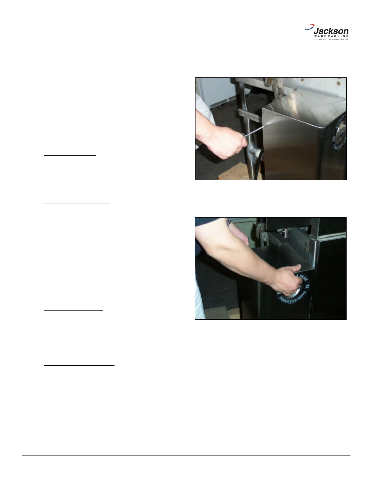
1. Remove the (2) screws that secure the top drive assembly cover
3. Set the top cover to the side and out of the way so that it does
not become a trip hazard. From here, the next step will be to
remove the bottom cover. This will require using the 7/16” socket
with ratchet and most likely the 7/16” combination wrench. Do not
lose the hardware for the covers as your repair kits do not come
with the hardware necessary to replace these. If you do require
hardware that is not present in your kits, do not hesitate to contact
www.jacksonmsc.com
The drive motor and the gear reducer of your Jackson
rack conveyor are responsible for moving racks of ware through
the dishmachine. If needed to be replaced, these instructions will
show you how to get your machine up and running in the shortest
possible time.
Jackson offers all of the repair parts necessary for performing this task.
The instructions provided here are for maintenance personnel only. Unauthorized persons should not attempt any of the
steps contained in these instructions.
Warning: many of the instructions and steps within
this document require the use of tools. Only authorized per sonnel should ever perform any maintenance procedure on
the dishmachine!
PREPARATION
1. Power must be turned off to the unit at the service
breaker. Tag or lock out the service breaker to prevent accidental
or unauthorized energizing of the machine.
TOOLS REQUIRED
The following tools will be needed to perform this mainte-
nance evolution:
1. 7/16” socket and ratchet with extension
2. 9/16” socket and ratchet with extension
3. 7/16” combination wrench
4. 9/16” combination wrench
5. 3/4” combination wrench
6. 1/8” Allen wrench
7. 1/4” nutdriver
8. Large flathead screwdriver
9. Medium phillipshead screwdriver
10. Medium hammer
11. Rubber mallet
STEPS
in place.
Removing the screws from the top cover.
2. Remove the top cover to expose the drive assembly.
TIME REQUIRED
It is estimated that it will take (1) person one and a quarter hours to replace the drive motor, one and a quarter hours to just
replace the gear reducer or two hours to do both at one time, not
including all of the items indicated in the section entitled “PREPA RATION”.
IMPORTANT NOTES
1. Read these instructions thoroughly before attempting
this maintenance procedure. Become familiar with the parts and
what actions need to be taken. This will save time in the long run!
2. The procedures demonstrated in this manual are
shown being performed on an AJ-44 rack conveyor dishmachine.
The actual maintenance steps, however, apply to any drive motor
or gear reducer found on a Jackson rack conveyor dishmachine.
Removing the top cover.
Jackson Technical Service for help.
2
Rack Conveyor Drive Motor and Gear Reducer Replacement Instructions
Revision A (07/05/2005)
Page 3
6. Once the bolts are removed, the motor should slide out of the
gear reducer. Remember to support and lay it gently on the floor or
some other surface in order to continue working on it. Be sure that
you get the key, checking the keyway on the motor shaft and in the
7. If the purpose of this maintenance action is to replace the drive
motor, continue to step 8. If you wish to replace the gear reducer,
8. With the motor laying on a level surface, you need to remove the
conduit from it. First, use the 1/4” nutdriver to remove the wiring
9. Once the cover is removed and the wiring is exposed, you may
want jot down how your motor is wired. You can also refer to the
schematic located on the motor itself because how the motor is
wired when you remove it is how you will wire it when you replace
it. If you have any questions regarding the wiring of your motor, do
10. pull the bundled wires out and remove the wire nuts. Set the
wire nuts to the side as you will need them when you wire up the
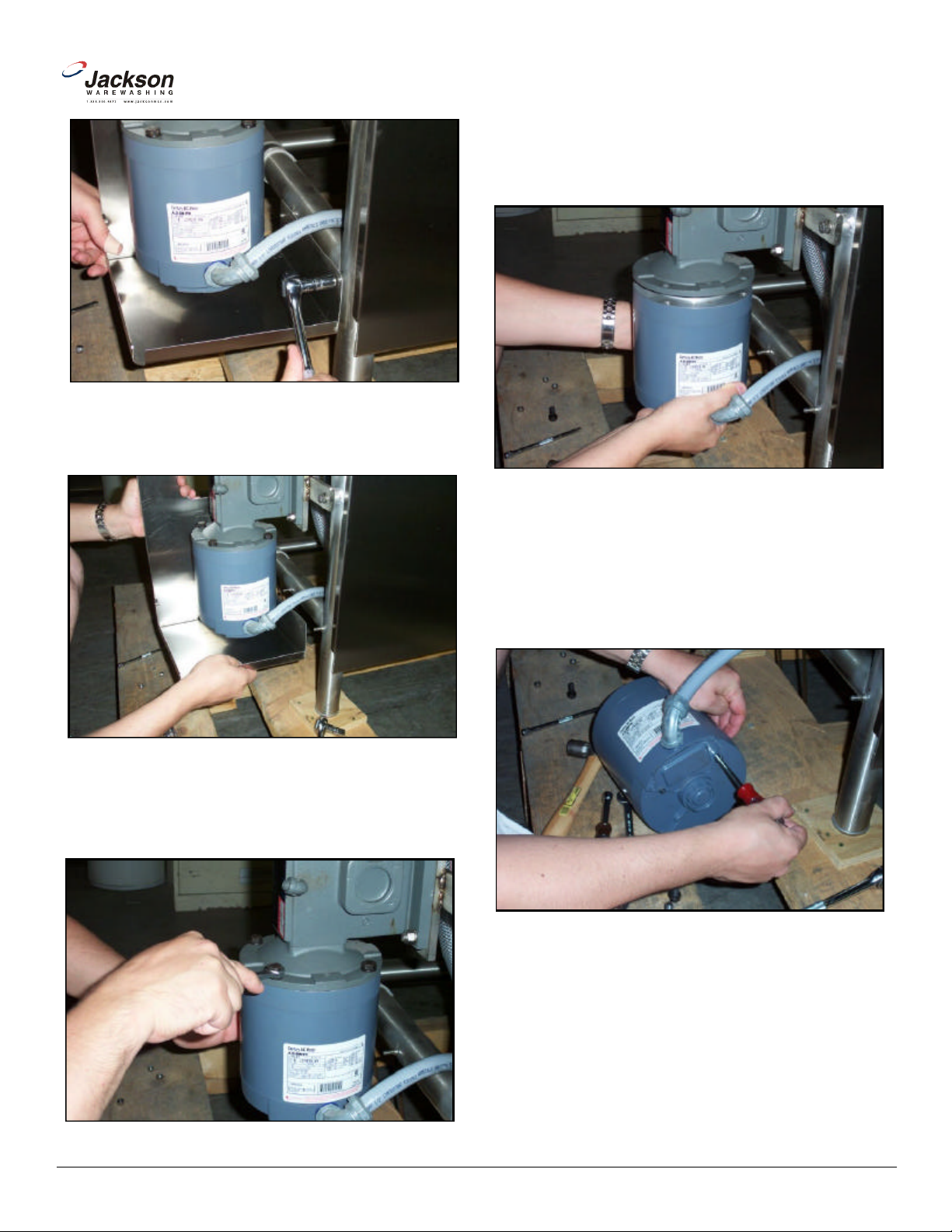
Removing the nuts securing the bottom cover.
4. Remove the bottom and set to the side so that it does not
become a trip hazard.
www.jacksonmsc.com
gear reducer.
Removing the drive motor.
Removing the bottom cover.
5. With the cover removed you may now remove the bolts used to
connect the drive motor to the gear reducer. Note: you need to
support the motor as you remove the bolts; failure to do so could
result in the motor falling to the ground and becoming damaged.
continue to step 21.
access cover on the back of the motor.
Removing the wiring access cover.
Removing the bolts holding the drive motor to the gear reducer.
Rack Conveyor Drive Motor and Gear Reducer Replacement Instructions
Revision A (07/05/2005)
not hesitate to contact Jackson Technical Service.
new motor.
3
Page 4

20. Proceed to the sections entitled “AFTER MAINTENANCE
21. (Continuing from step 7) To remove the gear reducer, first take
www.jacksonmsc.com
Removing the wire nuts.
11. Once the wire nuts are removed, separate the wires.
12. With the flathead screwdriver and the hammer, loosen the conduit nut. Once loosened, pull the conduit away from the motor. The
motor may now be disposed of.
13. Remove the access cover off of the new motor.
14. Attach the conduit and pull the wires through the hole provid ed. Tighten the conduit nut.
15. Using the wire nuts, wire the motor back the same way the old
one had been. Refer to the schematic on the motor itself or contact
Jackson Technical Service if you any questions.
16. Once the wiring is done, carefully push wires back into the
motor and put the access cover back on. Tighten down the screws
for securing it.
17. The drive motor now needs to be reattached to the gear reducer. There are two methods for doing this. The first is to try and and
reinsert the drive motor shaft into the gear reducer with it (gear
reducer) still attached to the unit. This is difficult but possible.
Ensure that the key is in the keyway when you mate the parts. The
second method and perhaps the easiest is to remove the gear
reducer, mate the two parts and bolt them together and then put
them on the unit at one time. This method takes a little more time.
If you wish to remove the gear reducer and assemble the two components continue on to step 27.
The WRONG way to mount the drive motor.
The Correct way to mount the drive motor.
19. Reattach the bottom and top drive assembly covers.
ACTIONS”.
the 3/4” combination wrench and remove the drive hub bolt.
18. Once the motor and gear reducer are mated, secure them with
the locknuts and bolts. Ensure the bolts are tight.
Note: Because of the way the covers for the drive assembly are
designed, it is imperative that you position the motor on the gear
reducer so that the conduit fitting is facing towards the front of the
dishmachine. If it is facing away from the machine, the covers may
not go back on.
Removing the drive hub bolt.
4
Rack Conveyor Drive Motor and Gear Reducer Replacement Instructions
Revision A (07/05/2005)
Page 5

22. Once the drive hub bolt & bearing are removed, loosen the set
25. Set the gear reducer on a flat surface. The drive hub needs
tobe removed. You have already loosened the set screw, but it may
take some more effort to remove it. You may have pry it off, or give
it some taps with a mallet to coax it off of the shaft. The liberal use
gear reducer. Ensure the key is in the keyway. Once it is on and
flush with the end of the shaft, tighten down on the set screw with
27. As you have both the drive motor and the gear reducer off of
the machine, it is much simpler to assemble them together prior to
mounting them. Ensuring that the key for the drive shaft of the drive
28. After the motor is mated against the gear reducer, turn the
motor so that the conduit fitting will face towards the front of the
dishmachine once both components are mounted to the frame.
This is to all the drive assembly covers to go back on. If you do not
do this, then there is a possibility the covers will not fit back on the
-
screw on the drive hub. There is no need to remove it.
Loosening the set screw with the 1/8 allen wrench.
www.jacksonmsc.com
of spray lubricants will also help.
23. Remove the gear drive by using the 9/16” socket and ratchet,
as well as the combination wrench as required, to remove the nuts
holding it to the mounting plate.
Removing the nuts holding the gear reducer on.
24. Gently remove the gear reducer, careful not to drop it.
Removing the drive hub.
26. Once the drive hub is removed, place it on the shaft of the new
the 1/8” allen wrench.
motor is in the keyway.
Removing the gear reducer.
Rack Conveyor Drive Motor and Gear Reducer Replacement Instructions
Revision A (07/05/2005)
Mounting the motor to the gear reducer.
unit. Refer to step 18 and the note following for more details.
29. Stand the assembly up and secure them using the lockwash
ers and bolts. Use the 9/16” combination wrench to tighten them
down.
5
Page 6

www.jacksonmsc.com
Reconnect the incoming water (if disconnected) and turn
-
utes, running an empty rack through the machine to ensure that it
is carried all of the way through. If you hear any grinding sounds
while the motor is running, immediately shut off the unit and secure
power and water. There is a serious problem that must be
addressed. If any problems arise you can contact Jackson
-
-
ning this or any other maintenance evolution on a unit under war
-
ranty, you should contact a certified Jackson technician or Jackson
Technical Service. You can find a list of qualified service agencies
Jackson MSC Inc. provides technical support for all of the
dishmachines detailed in this manual. We strongly recommend that
-
port staff. Please have this manual with you when you call so that
our staff can refer you, if necessary, to the proper page. Technical
support is available from 8:00 a.m. to 5:00 p.m. (EST), Monday
through Friday. Technical support is not available on holidays.
Contact technical support toll free at 1-888-800-5672. Please
remember that technical support is available for service personnel
Tightening the bolts to secure the drive motor to the gear reducer.
30. Once the motor is securely fastened to the gear reducer, carefully lift the assembly up and mount it on the fasteners. Be sure to
use proper lifting techniques to prevent injury.
AFTER MAINTENANCE ACTIONS
on. Then restore power to the unit. Run the unit for at least 10 min
Technical Service.
SPECIAL NOTES
Work performed on Jackson dishmachines by unautho
rized or unqualified personnel may void the warranty. Before begin
in the back of you unit’s installation manual.
SPECIAL PARTS
31. Once mounted, secure with the lockwashers and locknuts.
32. Reinstall the drive hub bearing and drive hub bolt, tightening
down with the 7/8” combination wrench.
33. Reattach the bottom and top assembly covers.
AJ-44/66/80 Machines:
Gear Reducer: 6105-011-71-88
Drive Motor Replacement Kit:
50 Hz: 6401-003-08-41
60Hz/1 Ph: 6401-003-08-42
60 Hz/3 Ph: 6401-003-08-40
600 V/60 Hz/3 Ph: 6401-003-08-43
AJ-54/76/90 Machines:
Gear Reducer: 6105-011-87-20
Drive Motor Replacement Kit:
50 Hz: 6401-003-08-41
60 Hz/1 Ph: 6401-003-08-42
60 Hz/3 Ph: 6401-003-08-40
600 V/60 Hz/3 Ph: 6401-003-08-43
AJ-64/86/100 Machines:
Gear Reducer: 6105-011-87-20
Drive Motor Replacement Kit:
50 Hz: 6401-003-08-41
60 hz/1 Ph: 6401-003-08-42
60 Hz/3 Ph: 6401-003-08-40
600 V/60 Hz/3 Ph: 6401-003-08-43
CONTACT INFORMATION
you refer to this manual before making a call to our technical sup
only.
6
Rack Conveyor Drive Motor and Gear Reducer Replacement Instructions
Revision A (07/05/2005)
Page 7

Drive Assembly (with Adjust-A-Peak)
www.jacksonmsc.com
Mounting Plate
Gear Reducer
Drive Hub Bearing & Bolt
Drive Motor
Rack Conveyor Drive Motor and Gear Reducer Replacement Instructions
Revision A (07/05/2005)
7
 Loading...