


tecMIG 450 / 600
mit Steuerbox MC 1 oder 2
und Koffer DVK 3 oder DVK 4
with control box MC 1 or 2
and wire feed case DVK 3 or DVK 4
Deutsch
(Seite 1-26,54-68)
English
(Page 27-68)

Allgemeine Informationen:
Diese Betriebsanleitung soll Sie dabei unterstützen, mit dem Schweißgerät effektiv und sicher zu
arbeiten.
Bitte lesen Sie die Anleitung vor Inbetriebnahme der Anlage gründlich durch.
Die Informationen dieser Betriebsanleitung müssen dem Bedienungspersonal zugänglich gemacht
werden. Die Anleitung sollte als Nachschlagewerk immer griffbereit in der Nähe der Anlage sein.
Warnung:
Elektromagnetische Verträglichkeit EMV (DIN EN 60974-10):
Diese Klasse A Schweißeinrichtung ist nicht für den Gebrauch in Wohnbereichen vorgesehen,
in denen die Stromversorgung über ein öffentliches Niederspannungsversorgungssystem
erfolgt. Es kann, sowohl durch leitungsgebundene als auch abgestrahlte Störungen, möglicherweise
schwierig sein, in diesen Bereichen elektromagnetische Verträglichkeit zu gewährleisten.
INFORMATION: Der Anwender ist für Störungen verantwortlich, die vom Betrieb der Anlage ausgehen.
Er muss mögliche elektromagnetische Probleme in der Umgebung bewerten und berücksichtigen.
Hinweis:
Sicherheitsprüfung:
Die Anlage muss aus Sicherheitsgründen mindestens einmal im Jahr durch die Fa. JÄCKLE oder
einen anderen autorisierten Fachmann einer Sicherheitsprüfung
nach DIN IEC 60974 Teil 4:
Sicherheit, Instandhaltung und Prüfung von Lichtbogenschweißeinrichtungen im Gebrauch
unterzogen werden!
Netzanschlussleitung und Netzstecker:
Laut Norm DIN EN 60974 – Teil 1, Punkt 10.9 und 10.10, Absatz b)
…müssen diese für den größten effektiven Netzstrom I
Sie müssen NICHT nach dem maximalen Netzstrom bemessen werden!
bemessen sein (siehe Leistungsschild)…
1eff
Gewährleistung:
Unsachgemäße Reparatur oder Wartung, technische Veränderung des Produktes, eigenmächtige,
nicht ausdrücklich von Jäckle GmbH angeordnete oder gestattete Eingriffe, sowie Fahrlässigkeit
beim Einbau bzw. Gebrauch oder die Außerachtlassung der Sorgfalt in eigenen Angelegenheiten
führen zum Erlöschen jeglicher Gewährleistungsansprüche.
Schutzvermerk nach DIN ISO 16016 beachten
Irrtümer und technische Änderungen vorbehalten !
Version 2.1
Juli / July 2014

tecMIG 450/600
EG-KONFORMITÄTSERKLÄRUNG
Hersteller: Jäckle Schweiß- und Schneidtechnik GmbH
Riedweg 4+9
D – 88339 Bad Waldsee
Hiermit erklären wir, dass nachfolgend aufgeführte Stromquelle den Sicherheitsanforderungen der EGRichtlinien entspricht.
Bezeichnung der Anlagen: Schweißstromquelle für MIG / MAG
Typ der Anlagen: tecMIG 450, 600
Einschlägige EG-Richtlinien:
EMV-Richtlinie 2004/108/EG (seit 20.07.2007)
Niederspannungsrichtlinie 2006/95/EG (seit 16.01.2007)
Angewandte harmonisierte Normen
EN 60 974 – Teil 1 Lichtbogenschweißeinrichtungen / Schweißstromquellen
EN 60 974 – Teil 5 Lichtbogenschweißeinrichtungen / Drahtvorschubgeräte
EN 60 974 – Teil 10 EMV Produktnorm für Lichtbogenschweißeinrichtungen
Zusätzliche Information:
Beschränkter Einsatzbereich, Klasse A Schweißeinrichtung
Jäckle Schweiß- und Schneidtechnik GmbH
Reinhard Jäckle
Betriebsanleitung Seite 1

tecMIG 450/600
Inhalt
Inhaltsverzeichnis Seite
1. Kurzbeschreibung ......................................................................................................................................... 2
2. Technische Daten .......................................................................................................................................... 3
3. Umgebungsbedingungen ............................................................................................................................. 3
4. Sicherheitshinweise ...................................................................................................................................... 4
5. Übersicht Steuerungsfunktionen ................................................................................................................. 7
6. Bedienelemente ............................................................................................................................................. 8
7. Steuerung MC 1 ............................................................................................................................................. 9
8. Steuerung MC 2 ........................................................................................................................................... 10
9. Funktionsbeschreibung .............................................................................................................................. 11
10. Inbetriebnahme / Schweißen .................................................................................................................. 15
11. Drahtvorschub DVK 3 / DVK 4 ................................................................................................................ 18
12. Fernbedienungsdose .............................................................................................................................. 19
13. Schweißbrenner mit Display / Job - Reihenfolge ................................................................................. 20
14. Schweißbrennerkühlung / Kühlmittel JPP ............................................................................................ 21
15. Pflege und Sicherheitsprüfung .............................................................................................................. 21
16. Übertemperatur........................................................................................................................................ 22
17. Störungen, Fehler, Ursache und Beseitigung ...................................................................................... 22
18. Fehlertabelle ERROR CODES: ............................................................................................................... 24
19. Materialtabelle ......................................................................................................................................... 25
39. Ersatzteile / spare parts .......................................................................................................................... 54
40. Schaltpläne / circuit diagrams ............................................................................................................... 65
1. Kurzbeschreibung
Die MIG/MAG - Schweißanlagen tecMIG 450 / 600 wurden für den industriellen Einsatz entwickelt. Ihre
Ausstattung und Funktionsweise wurden deshalb für die professionelle Nutzung ausgelegt.
Stufenlose Schweißleistungseinstellung
Steuerungsfunktionen
Siehe Beschreibung Steuerbox MC
Drahtvorschub mit 4-Rollenantrieb
Kühlung der Stromquelle durch geräuscharmen Ventilator.
Der Ventilator wird über einen Thermostat eingeschaltet und läuft erst, wenn sich die Stromquelle erwärmt hat.
In den Schweißpausen schaltet der Ventilator ab, sobald die Stromquelle wieder abgekühlt ist.
Thermischer Überlastschutz
Sollte durch extrem hohe Belastung oder Umgebungstemperatur die zulässige Betriebs-Temperatur
überschritten werden, schaltet ein eingebauter Thermoschalter den Schweißstrom ab.
Zentralanschlussbuchse
Die Zentralanschlussbuchse ermöglicht ein schnelles An- und Abkoppeln des Schweißbrenners.
Zeichen S
besagt, dass die Anlage auch für das Schweißen unter erhöhter elektrischer Gefährdung nach Euronorm
EN 60 974-1 verwendet werden kann.
Betriebsanleitung Seite 2

tecMIG 450/600
2. Technische Daten
Stromquelle tecMIG 450 tecMIG 600
Netzspannung, 50 Hz 400 V, 3 Phasen, +/- 10% 400 V, 3 Phasen, +/- 10%
Stromaufnahme Imax = 32 A, Ieff = 25A Imax = 58 A, Ieff = 45A
Sicherung 32 A träge 63 A träge
Max. Leistungsaufnahme 23 kVA 39 kVA
Einstellbereich 50 - 450 A 50 - 600 A
Arbeitsspannung 16,5 – 36,5 V 16,5 – 44 V
Leerlaufspannung 17 - 49 V 20 - 62 V
Einschaltdauer 60 % (40°C) 450 A / 36,5 V 600 A / 44 V
Einschaltdauer 100 % (40°C) 330 A / 30,5 V 450 A / 36,5 V
Schutzart IP 23 IP 23
Isolationsklasse H (180° C) H (180° C)
Kühlart F F
Gewicht (solo) 179 kg 244 kg
Maße L x B x H (mm) 1070 x 490 x 945 1100 x 500 x 1000
Geräuschemission < 70 dB(A) < 70 dB(A)
Drahtvorschub DVK 3 DVK 4
Drahtvorschubmotor 42 V, 100 W 42 V, 140 W
Fördergeschwindigkeit 0,8 - 24 m/min 0,8 - 24 m/min
Drahtdurchmesser 0,8 - 1,6 mm 0,8 - 1,6 mm
Gewicht (solo) 20 kg 28 kg
Maße L x B x H (mm) 580 x 270 x 560 650 x 450 x 360
Zulassung für das Schweißen unter erhöhter elektrischer Gefährdung
Herstellung gemäß Euronorm EN 60 974-1 und EN 60 974-10
Generatorbetrieb:
Der Generator muss mindestens 30% mehr Leistung erzeugen, als die maximale Leistung des Gerätes.
Beispiel: 23kVA (Gerät) + 30% = 30kVA. Für dieses Gerät muss ein 30kVA Generator verwendet werden.
Ein kleinerer Generator führt zur Beschädigung des Jäckle Schweißgerätes, sowie des Generators und
darf daher nicht verwendet werden!
3. Umgebungsbedingungen
Die Schweißstromquelle darf nur bei einer Temperatur zwischen -10°C und +40°C, sowie einer relativen
Luftfeuchte von bis 50% bei +40°C oder bis 90% bei +20°C betrieben werden.
Die Umgebungsluft muss frei von unüblichen Mengen an Staub, Säuren, korrosiven Gasen oder Substanzen
usw. sein, soweit diese nicht beim Schweißen entstehen.
Um Schäden an der Maschine zu verhindern überwacht die Steuerung die Umgebungstemperatur der Maschine.
Liegt diese Temperatur unter -10°C oder über + 40°C erscheint folgender Text im Display, und die Maschine
kann nicht gestartet werden.
t°C - int - ‚gemessener Temperaturwert’
Erst wenn die Temperatur im vorgeschriebenen Bereich liegt, kann der Schweißvorgang gestartet werden.
Betriebsanleitung Seite 3

4. Sicherheitshinweise
Die Anlage ist nach den einschlägigen internationalen Normen gebaut.
a)
Die Anlage ist ausschließlich für das MIG/MAG - Schweißen bestimmt.
Wie bei jedem technischen Produkt können von den Anlagen bei unsachgemäßer oder nicht
bestimmungsgemäßer Nutzung Gefahren ausgehen.
Das Bedienungspersonal muss über die Sicherheitshinweise unterrichtet werden. Die Anlage
darf nie von ungeschultem Personal bedient werden.
1 Brand bzw. Explosionsverhütung
2 Verhütung von elektrischen Schlägen
b) Reparaturen im elektrischen Bereich dürfen nur von Elektrofachkräften ausgeführt werden.
c) Bei Pflege-, Wartungs- und Reparaturarbeiten sowie vor Öffnen des Gehäuses immer
Netzstecker ziehen.
d) Die Anlage ist stets in einem funktionstüchtigen Zustand zu halten
e) Modifikationen an der Anlage sind verboten.
f) Die Schweißanlage ist ausschließlich für obige Anwendungen konstruiert und anzuwenden.
Das Auftauen von Rohrleitungen ist verboten.
Die nachfolgend aufgeführten Sicherheitsbestimmungen sind zu beachten.
Durch den Aktionsraum bedingt, sind in der Nähe arbeitende Personen, ebenfalls vor eventuellen
Gefahren zu schützen.
Brennbare Stoffe sind von der Schweißzone fernzuhalten. Sie könnten sich durch Funken und
heiße Schlacke entzünden.
Warnung:
Brennbare Materialien entfernen (Abstand mindestens 10 m)
Heiße Metallteile und Schmelze abkühlen lassen.
Entflammbare Bereiche zuerst entlüften.
Keine Behälter schweißen die brennbare Materialien enthalten (auch keine Reste davon;
Gefahr entflammbarer Gase!)
Die Anlage nicht in Betrieb nehmen, wenn die Umgebungsluft explosiven Staub oder Gase enthält.
(Anwender muss gegebenenfalls Messungen durchführen).
Behälter bzw. Rohre, die sich im Über- bzw. Unterdruck befinden, dürfen nicht geschweißt werden.
(Explosions- bzw. Implosions-Gefahr!)
Beim Schweißen von Aluminium können sich entflammbare Schlacken und Stäube (Rauch) bilden.
Beachten Sie eine erhöhte Brand- bzw. Explosionsgefahr.
Warnung:
Das Berühren stromführender Teile kann tödliche elektrische Schläge oder schwere
Verbrennungen verursachen.
Beim Schweißen entsteht ein Stromkreis über den Brenner, das Werkstück (alle damit
verbundenen Teile) und das Massekabel, zurück in die Anlage. Dieser Stromkreis darf während des
Schweißens nicht direkt berührt bzw. unterbrochen werden.
Die Massezange muss mit einwandfreiem metallischem Kontakt am Werkstück angebracht sein, im
Nahbereich des zu schweißenden Teils.
Der Schweißstrom muss vom Brenner über das Werkstück durch das Massekabel zurück in die
Anlage fließen. Bei falscher Kontaktierung des Werkstück- bzw. Massekabels kann der
Schweißstrom über eine indirekte Verbindung fließen und dort zu Schaden führen, z.B. über die
Schutzleiter-Installation (PE, Erde).
tecMIG 450/600
Betriebsanleitung Seite 4

tecMIG 450/600
3 Strahlung
Handschuhe und Schuhe sind zu tragen, die ausreichende Isolierung bieten. Die gesamte Kleidung
ist trocken zu halten.
Erhöhte Vorsicht gilt in einer Umgebung mit hoher Feuchtigkeit!
Alle an der Anlage angeschlossenen elektrischen Leitungen sind auf einwandfreien Zustand zu
überprüfen.
Warnung:
Blanke Stellen ohne bzw. mit schadhafter Isolierung sind lebensgefährlich. Beschädigte Kabel bzw.
Schlauchpakete sofort ersetzen!
Beim Wechsel der Brennerteile die Anlage am Hauptschalter außer Betrieb setzen.
Vor öffnen des Anlagengehäuses Netzstecker ziehen.
Die Anlagen sind in regelmäßigen Abständen auf Ihren einwandfreien Zustand zu prüfen,
hierfür gilt:
Die Strahlung des Lichtbogens kann zu Augenschäden und Hautverbrennungen
führen. Deshalb muss zum Schutz der Augen ein Schweißschild oder ein
Schutzhelm verwendet werden. Die Haut muss durch geeignete Schutzbekleidung
(Schweißerhandschuhe, Lederschürze, Sicherheitsschuhe) geschützt werden.
In der Nähe arbeitende Personen sind ebenfalls vor der Lichtbogenstrahlung zu
schützen. (mobile Trennwand, Vorhang, etc).
4 Schutz vor Lärm
Beim Gebrauch des Schweißgerätes entsteht großer Lärm, der auf Dauer das Gehör schädigt!
Im Dauereinsatz ist ein ausreichender Gehörschutz zu tragen.
In der Nähe arbeitende Personen sind ebenfalls vor Lärm zu schützen.
5 Rauchgas
Beim Schweißen entstehen Rauchgase bzw. toxische Dämpfe die zu Sauerstoffmangel in der
Atemluft führen. Deshalb darf die Schweißanlage nur in gut belüfteten Hallen, im Freien oder in
geschlossenen Räumen mit entsprechender Absaugung (am besten unterhalb der Schweißzone
absaugen) verwendet werden.
Der Schweißbereich des Werkstücks muss von Lösungs- und Entfettungsmitteln gereinigt
werden, um die Bildung von Giftgasen zu vermeiden bzw. zu vermindern.
Schweißen von Blei, auch in Form von Überzügen, verzinkten Teilen, Kadmium, "kadmierten
Schrauben", Beryllium (meist als Legierungsbestandteil, z.B. Beryllium-Kupfer) und anderen
Metallen, die beim Schweißen giftige Dämpfe entwickeln, ist nur mit Atemschutzmaske bzw. gerät, sowie scharfer Absaugung und Filterung der giftigen Gase und Dämpfe erlaubt.
Erhöhte Vorsicht gilt beim Schweißen von Behältern.
Betriebsanleitung Seite 5
6 Gasdruckausrüstung
tecMIG 450/600
Gasflaschen stehen unter hohem Druck und stellen eine Gefahrenquelle dar.
Beispielsweise müssen die Flaschen auf jeden Fall vor direkter Sonneneinstrahlung, vor offenem
Feuer und starken Temperaturschwankungen, z. B. sehr tiefen Temperaturen geschützt werden.
Der richtige Umgang mit ihnen ist unbedingt beim Gaslieferanten zu erfragen.
Gasbehälter und –zubehör sind in einwandfreiem Zustand zu halten. Achten Sie darauf, dass nur
zugelassene Teile, wie Schläuche, Kupplungen, Druckminderer usw. eingesetzt werden.
Achtung:
Anschlüsse dürfen nicht mit Öl bzw. Fett geschmiert werden (Selbstentzündungsgefahr)
7 Weitere Vorschriften
Neben den Hinweisen in dieser Betriebsanleitung sind die allgemeingültigen Sicherheitsvorschriften zu
beachten.
Außerdem weisen wir darauf hin, dass die Anlagen in bestimmten Einsatzbereichen trotz eingehaltener
Aussendungsgrenzwerte elektromagnetische Störungen verursachen können und dass diese Störungen im
Verantwortungsbereich des Anwenders liegen.
Personen, die Herzschrittmacher oder Hörgeräte tragen, sollten sich vor Arbeiten
in der Nähe der Maschinen, von einem Arzt beraten lassen.
Achtung:
Es ist möglich, dass im Bereich eines Krankenhauses oder ähnlichem durch den
Betrieb der Anlage elektromedizinische, informationstechnische oder auch andere
Geräte (EKG,PC, ...) in ihrer Funktion beeinträchtigt werden können.
Vor Inbetriebnahme der Anlagen ist daher sicherzustellen, dass der Betreiber
solcher oder ähnlicher Geräte, vom Anwender vorher informiert werden.
Entsprechende Hilfen zur Bewertung des Einsatzbereichs und zur Minimierung von elektromagnetischen
Störungen (z.B. Gebrauch abgeschirmter Leitungen) sind der EMV-Produktnorm für
Lichtbogenschweißeinrichtungen zu entnehmen:
EN 60 974-10 (Elektromagnetische Verträglichkeit EMV)
8 Entsorgung der Maschine
Geben Sie Elektro-Altgeräte nicht zu normalem Hausmüll!
Unter der Berücksichtigung der EG-Richtlinie 2002/96 für Elektro- und ElektronikAltgeräte und ihrer Umsetzung in Anlehnung an das nationale Recht müssen Elektroausrüstungen, die das Ende ihrer Lebensdauer erreicht haben, getrennt gesammelt
und einer zuständigen, umweltverantwortlichen Wiederverwertungsanlage übergeben
werden. Gemäß den Anweisungen der Gemeindebehörden ist der Eigentümer der
Ausrüstung verpflichtet, einer regionalen Sammelzentrale eine außer Betrieb gesetzte
Einheit zu übergeben.
Weitere Information finden Sie im Internet unter dem Stichwort ‚WEEE’.
Betriebsanleitung Seite 6

tecMIG 450/600
5. Übersicht Steuerungsfunktionen
Funktionen MC 1 MC 2
Thyristor Schweißanlagen ■ ■
Handbetrieb ■ ■
Automatikbetrieb ■ ■
Lichtbogenlängenkorrektur ■ ■
Materialauswahl ■ ■
Leistung individuell einstellbar ■ ■
MIG Modus ■ ■
WIG Modus - mit Gasvorströmzeit und Slopedown Zeit einstellbar ■ ■
Elektroden Modus - mit Hotstart / Arcforce einstellbar ■ ■
2-Takt, 4-Takt, Punkten ■ ■
Kraterfüllen – Hotstart - Absenken ■
Individuelle Jobs abspeichern / löschen (100 Stück) ■
Gas Test ■ ■
Draht einfädeln ■ ■
Kühlmittel Durchflussanzeige ■
Kühlmitteldurchfluss Minimum einstellbar ■
Leistungsauswahl über Materialstärke direkt ■ ■
Einschleichen (Sts) einstellbar ■ ■
Drahtrückbrand (bUb) einstellbar ■ ■
Gasvorströmen (PrG) einstellbar ■
Gasnachströmen (PoG) einstellbar ■
Punktzeit (Spt) einstellbar ■ ■
Drosselstärke individuell veränderbar ■ ■
Fernbedienungsfunktionen einstellbar ■
Schweißleitungslängen einstellbar ■
Wasserpumpe Ein/Aus ■
Maschinentyp einstellbar ■
Softwareupdate für Kurven ■ ■
Steuerung sperren / entsperren (Code) ■
Lüfter / Wasserpumpe (wenn vorhanden) geregelt ■ ■
Display HOLD Zeit einstellbar ■ ■
Steuerung zurücksetzen auf Werkseinstellungen (Reset) ■ ■
Betriebsanleitung Seite 7

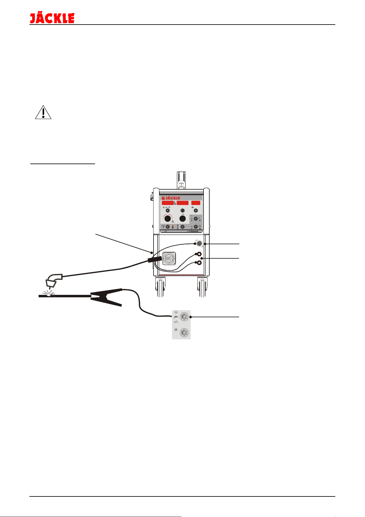
Massebuchse
Workpiece socket
+ Buchse Elektrode / WIG
Anschluss up/down Brenner
Connection up/down torch
Wasservorlauf ‘blau-kalt’ DN 5
Wasserrücklauf ‘rot-heiß’ DN 5
Gaseingang
Main cable
Rückseite / back side
tecMIG 450/600
6. Bedienelemente
Brenner
Zentralanschluss
Central
torch connection
Kontrollleuchten Netz
Control lamp main
Primärsicherung
Main fuse
MC 1
V A
S %
sec l/mi n
mm
F
X
LADEN
TEST
SPEICHERN
V
T 2A
Steuerbox MC 1 oder 2
Control unit MC 1 or 2
water runback ‘red-hot’ DN 5
water flow ‘blue-cold’ DN 5
Hauptschalter
Main switch
+ socket MMA / TIG
Fernbedienungsbuchse 17-polig
Remote control socket 17-pole
Gasausgang
Gas output
Betriebsanleitung Seite 8
+ Buchse / socket
Datenleitung zum Koffer
Communication to wire feed case
Wasserrücklauf ‘rot-heiß’ DN 5
water runback ‘red-hot’ DN 5
Wasservorlauf ‘blau-kalt’ DN 5
water flow ‘blue-cold’ DN 5
Gas input
Netzkabel

Elektrode
7. Steuerung MC 1
tecMIG 450/600
1 – Anzeige Display Drahtgeschwindigkeit in m/min (HAND-9), bzw. Korrektur von -3.0V bis +3.0V der Licht-
bogenlänge (AUTO-9), blinkender Punkt: HOLD Funktion aktiv
2 – LED Anzeige ob 2-Takt, 4-Takt, 2-Takt - Punkten oder 2T/4T Kraterfüllen aktiv ist
3 – Bedientaste um zwischen 2-Takt, 4-Takt, 2-Takt - Punkten oder Kraterfüllen
durch tippen umzuschalten
4 – LED Anzeige der Einheiten % oder Sekunde, wenn solche Werte im mittleren
Display (10) angezeigt werden
5 – Bedientaste Fx zum Einstellen der Schweißfunktionen (z.B. Drosselhärte, ..- antippen kürzer als
0,5 Sekunden) bzw. der Optionen (z.B. Fernbedienung,…- drücken länger als 1 Sekunde)
6 – Drehknopf um die Materialart einzustellen, die Lichtbogenlänge zu korrigieren (AUTO-9), die Draht-
geschwindigkeit in m/min (HAND-9) einzustellen, bzw. um alle Werte im linken Display zu ändern
7 – Drehknopf um Schweißleistung, alle Funktionen, Optionen, Materialdicke oder sonstige Werte im mittleren
oder rechten Display einzustellen
8 – Bedientaste für die Materialauswahl (antippen kürzer als 0,5 Sekunden), bzw. Einstellung Hand oder
Automatikbetrieb (drücken länger als 1 Sekunde)
9 – LED Anzeige, ob HAND- oder AUTOmatikbetrieb aktiviert ist
10 – Anzeige Display für die Schweißspannung in Volt, blinkender Punkt: HOLD Funktion aktiv, des weiteren die
veränderbaren Funktions- und Optionswerte
11 – Anzeige Display für den Schweißstrom in Ampere oder die Materialdicke, sowie die Kühlflüssigkeits-
durchflussmenge, und weitere Parameter
12 – LED Anzeige für Materialdicke in mm bzw. Wasserdurchfluss in l/min
13 – Bedientaste um zwischen Schweißstrom und Materialdicke (antippen kürzer als 0,5 Sekunden), bzw.
Wasserdurchfluss (drücken länger als 1 Sekunde) umzuschalten
14 – Bedientaste um die Programme aufzurufen und zu laden (antippen kürzer als 0,5 Sekunden), bzw. den
Gastest zu aktivieren (drücken länger als 1 Sekunde)
15 – Bedientaste um die Drahteinfädelfunktion zu aktivieren oder um Programme zu speichern
16 – Bedientaste Mode um zwischen den Betriebsarten MIG, Elektrode und WIG umschalten zu können
17 – LED Anzeige, ob die Betriebsart MIG, Elektrode oder WIG aktiviert ist
MIG
WIG
Betriebsanleitung Seite 9

V
TEST
A
MC 2
8
9
10
11
12
13
14
15
Punkten
A
Materialdicke
Elektrode
8. Steuerung MC 2
1
2
3
4
5
6
tecMIG 450/600
7
1 – Anzeige Display Drahtgeschwindigkeit in m/min (HAND-7), bzw. Korrektur von -3.0V bis +3.0V der Licht-
bogenlänge (AUTO-7), blinkender Punkt: HOLD Funktion aktiv
2 – LED Anzeige ob 2-Takt, 4-Takt oder 2-Takt - Punkten aktiv ist
3 – Bedientaste um zwischen 2-Takt, 4-Takt, 2-Takt - Punkten durch tippen umzuschalten
4 – Drehknopf um die Materialart einzustellen, die Lichtbogenlänge zu korrigieren (AUTO-7), die Draht-
geschwindigkeit in m/min (HAND-7) einzustellen, bzw. um alle Werte im linken Display zu ändern
5 – Drehknopf um die Schweißleistung im mittleren Display einzustellen
6 – Bedientaste für die Materialauswahl (antippen kürzer als 0,5 Sekunden), bzw. Einstellung Hand oder
Automatikbetrieb (drücken länger als 1 Sekunde)
7 – LED Anzeige, ob HAND- oder AUTOmatikbetrieb aktiviert ist
8 – Anzeige Display für die Schweißspannung in Volt, blinkender Punkt: HOLD Funktion
9 – Anzeige Display für den Schweißstrom in Ampere oder die Materialdicke, sowie die Drossel, Einschleich-
geschwindigkeit und die Drahtrückbrandzeit
10 - LED Anzeige ob Einschleichgeschwindigkeit, Drahtrückbrandzeit, Materialdicke oder Schweißstrom
angezeigt wird
Ein-
schleichen
Rückbrand
Schweißstrom
11 – Bedientaste um zwischen Drosselhärte, Einschleichgeschwindigkeit, Drahtrückbrandzeit, Materialdicke und
dem Schweißstrom (bei eingeschaltetem Punkten die Punktzeit) umzuschalten
12 – Bedientaste um den Gastest zu aktivieren, bzw. um im Einstellmodus die Werte von Drossel, Einschleich geschwindigkeit, Drahtrückbrandzeit zu, Materialdicke und Leistung zu erhöhen (LED 10 blinkt)
13 – Bedientaste um die Drahteinfädelfunktion zu aktivieren bzw. um im Einstellmodus die Werte von Drossel,
Einschleichgeschwindigkeit, Drahtrückbrandzeit zu, Materialdicke und Leistung zu verkleinern
(LED 10 blinkt)
14 – Bedientaste Mode um zwischen den Betriebsarten MIG, Elektrode und WIG umschalten zu können
15 – LED Anzeige, ob die Betriebsart MIG, Elektrode oder WIG aktiviert ist
4-Takt
2-Takt
MIG
WIG
Betriebsanleitung Seite 10

tecMIG 450/600
9. Funktionsbeschreibung
• 2-Takt, 4-Takt, Punkten (MC 1-2), Kraterfüllen (MC 1)
Durch tippen auf die Bedientaste (3) kann zwischen 2-Takt, 4-Takt, 2-Takt Punkten (MC 1-2) und
2T/4T Kraterfüllen (MC 1) um geschalten werden. Die jeweils aktivierte Funktion wird durch die LED
angezeigt.
Kraterfüllprogramm MC 1 (Led S):
CSC (%)
100%
StS(%)
PrG(s)
2-Takt
2-Cycle
4-Takt
4-Cycle
tCSC(s)
2-Takt: Der Brennertaster wird gedrückt, und der Lichtbogen wird nach der Gasvorströmzeit (PrG) mit dem
voreingestellten Hot-Start Strom (CSC) gezündet. Nach Ablauf der Start-Start Zeit (tCSC) fällt der
Strom auf den eingestellten Schweißstrom mit der Absenkgeschwindigkeit (SLO) ab. Der Brennertaster
wird losgelassen, und der Strom fällt auf den eingestellten Krater Endschweißstrom (CEC) mit
der Absenkgeschwindigkeit (SLO) ab. Nach Ablauf der Endkrater Zeit (tCEC) geht der Lichtbogen aus.
Das Schutzgas strömt mit der eingestellten Zeit (PoG) nach.
4-Takt: Der Brennertaster wird gedrückt, und der Lichtbogen wird mit dem voreingestellten Hot-Start Strom
(CSC) gezündet. Der Schweißstrom bleibt auf diesem Wert. Der Brennertaster wird losgelassen,
und der Strom fällt auf den eingestellten Schweißstrom mit der eingestellten Absenkgeschwindigkeit
(SLO) ab. Der Brennertaster wird gedrückt und der Strom fällt auf den eingestellten Krater
Endschweißstrom (CEC) mit der eingestellten Absenkgeschwindigkeit (SLO) ab. Der Brennertaster wird
losgelassen, und der Lichtbogen geht aus. Das Schutzgas strömt mit der eingestellten Zeit (PoG)
nach.
Werkstoffauswahl (Material, Gas, Drahtdurchmesser) (MC 1-2)
Durch kurzes tippen auf die Materialtaste erscheint im linken Display die Materialart (z.B. Stahl), im
mittleren Display das Gas (z.B. Co2) und im rechten Display der Drahtdurchmesser (z.B. 1,0mm).
Durch drehen am linken Drehknopf kann nun die erforderliche Materialauswahl getroffen werden.
Die zuletzt im Display angezeigte Auswahl wird übernommen.
AUTOmatik / HANDbetrieb (MC 1-2)
Durch langes drücken der Materialtaste – länger als 1 Sekunde – wird zwischen Automatikbetrieb und
Handbetrieb umgeschaltet. Im Automatikbetrieb werden alle notwendigen Parameter zum schweißen
von der Steuerung automatisch eingestellt und gehalten.
Im Handbetrieb können Drahtvorschubgeschwindigkeit in m/min mit dem linken Drehknopf und ggf. die
Leistung mit dem mittleren Drehknopf unabhängig voneinander eingestellt werden
Leistungsauswahl / Materialdicke (MC 1-2)
Die Schweißleistung lässt sich bei den Steuerungen MC 1-2 mit dem mittleren Drehknopf verändern.
Dabei werden im Automatikmodus immer Drahtgeschwindigkeit, Schweißspannung, Drossel und
Schweißstrom geändert. Es besteht auch die Möglichkeit, anstatt dem Schweißstrom, die Materialdicke
anzeigen zu lassen.
Dazu ist nur auf die Bedientaste mm (MC 1) oder ► (MC 2) zu tippen, bis die LED mm oder das
Symbol Materialdicke leuchtet. Nun kann die erforderliche Materialdicke mit dem mittleren Drehknopf
(MC 1) oder den Tasten ▲ ▼ (MC 2) eingestellt werden.
• Lichtbogenlänge Korrektur (AUTO)
Für besondere Schweißaufgaben kann die Lichtbogenlänge verändert werden.
Durch drehen am linken Drehgeber kann die Lichtbogenlänge um 3V um den aktuellen Arbeitspunkt
verkleinert oder vergrößert werden (in 0,1V Schritten). Im linken Display wird die Änderung von -3.0V bis
+ 3.0V angezeigt. Im mittleren Display wird synchron dazu die neue Schweißspannung angezeigt.
Die Drahtvorschubgeschwindigkeit bleibt dabei immer konstant und wird nicht geändert.
Während des Schweißens wird mittels der Symbole └ oder ┌ im mittleren Display angezeigt, ob man
aktuell eine kleinere └ oder größere ┌ Schweißspannung eingestellt hat. Liegt man auf dem normalen
Arbeitspunkt, ist kein Symbol sichtbar.
SLO(V/s)
SLO
(V/s)
tCEC
CEC (%)
PoG(s)
(s)
Betriebsanleitung Seite 11

Funktionen Fx (MC 1)
Im Ruhezustand (wenn nicht geschweißt wird):
tecMIG 450/600
Durch kurzes antippen der Bedientaste Fx können folgende Funktionen für jede
Schweißkurve individuell eingestellt werden:
Betriebsart MIG:
- Drossel (Cho): Stufenlose Korrektur der Schweißdrossel
von ‚+15 Weicher’ bis ‚- 15 Härter’ als ‚0’ (Standard)
- Startgeschwindigkeit (StS): 10 bis 100% der Schweißgeschwindigkeit
- Drahtrückbrand (bUb): -60ms (lang, spitz) bis +90ms (kurz, Kugel Drahtende)
- Gasvorströmen (PrG): 0,0 bis 1,0 Sekunden
- Gasnachströmen (PoG): 0,5 bis 10 Sekunden
- *Krater Hotstart-Strom (CSC): -50% bis +100% des aktuellen Schweißstromes
- *Krater Hotstart-Zeit (tCSC): 0,1 bis 5,0 Sekunden
- *Endkraterfüll-Strom (CEC): -100% bis +50% des aktuellen Schweißstromes
- *Endkrater-Zeit (tCEC): 0,1 bis 5,0 Sekunden
- *Absenkgeschwindigkeit (SLO): 1Volt / Sekunde (langsam) bis 20V/s (schnell)
- Punktzeit (SPt): 0,5 bis 10 Sekunden
- Code (Code): zum Sperren der Steuerung (siehe nächste Seite)
* MC 1 nur bei Kraterfüllen (LED S) aktiv
Betriebsart Elektrode:
- Hotstart (HSt): 0 bis 150% des Schweißstromes
- Arcforce (Arcf): 100 bis 250% des Schweißstromes
Betriebsart WIG:
- Gasnachströmen (tPoG): 2 bis 20 Sekunden
- Strom Absenken (dSLP): 0,0 bis 10,0 Sekunden
Die Werte lassen durch drehen am mittleren Drehknopf in ihren Bereichen verändern. Wird der Wert für mehr
als 2 Sekunden nicht geändert, schaltet die Anzeige auf Standard um, und speichert den Wert ab.
Während des Schweißens:
Betriebsart MIG:
Während des Schweißvorganges kann durch tippen auf die Taste Fx die Drosselfunktion aufgerufen und
geändert werden. Im linken Display erscheint Choc, im mittleren Display steht der aktuelle Wert.
Nun kann mit dem mittleren Drehknopf der Wert zwischen -15 (hart) und + 15 (weich) geändert werden.
Wird im Automatikmodus geschweißt, kann durch ein weiteres tippen auf die Bedientaste Fx die aktuelle
Lichtbogenlänge Korrektur im mittleren Display angezeigt werden.
Nun kann mit dem linken Drehknopf der Wert zwischen -3.0V und + 3.0V geändert werden.
Funktionen MC 2
Im Ruhezustand (wenn nicht geschweißt wird):
Durch kurzes antippen der Bedientaste ► (11) können folgende Funktionen für jede
Schweißkurve individuell eingestellt werden:
Betriebsart MIG:
- Drossel (Anzeige Choc): Stufenlose Korrektur der Schweißdrossel
von ‚- 15 Härter’ bis ‚+ 15 Weicher’ als ‚0’ (Standard)
- Startgeschwindigkeit : 10 bis 100% der Schweißgeschwindigkeit
- Drahtrückbrand : -90ms bis +60ms
Die Werte lassen durch tippen auf die Tasten ▲ ▼ in ihren Bereichen verändern. Wird der Wert für mehr als 2
Sekunden nicht geändert, schaltet die Anzeige auf Standard um, und speichert den Wert ab.
Betriebsart Elektrode:
- Hotstart (Anzeige HSt): 0 bis 150% des Schweißstromes
- Arcforce (Arcf): 100 bis 250% des Schweißstromes
Betriebsart WIG:
- Gasnachströmen (tPoG): 2 bis 20 Sekunden
- Strom Absenken (dSLP): 0,0 bis 10,0 Sekunden
Die Werte lassen durch drehen am mittleren Drehknopf (MC 2) in ihren Bereichen verändern. Wird der Wert für
mehr als 2 Sekunden nicht geändert, schaltet die Anzeige auf Standard um, und speichert den Wert ab.
Betriebsanleitung Seite 12

tecMIG 450/600
Bei erneutem drücken der Bedientaste ► (11) wird immer zuerst der zuletzt geänderte Parameter angezeigt.
Durch erneutes tippen auf die Taste wird zum nächsten Parameter gewechselt.
Während des Schweißens:
Betriebsart MIG:
Während des Schweißvorganges kann durch tippen auf die Bedientaste ► die Drosselfunktion aufgerufen und
geändert werden. Im linken Display erscheint Choc, im rechten Display steht der aktuelle Wert.
Nun kann mit dem mittleren Drehknopf der Wert zwischen -15 und +15 geändert werden.
Durch ein weiteres tippen auf die Bedientaste ► wird die aktuelle Lichtbogenlänge Korrektur im mittleren Display
angezeigt. Nun kann mit dem linken Drehknopf der Wert zwischen -3.0V und + 3.0V geändert werden.
• Steuerung sperren – CODE (MC 1)
Die Steuerung für die Schweißaufgabe optimal einstellen.
Um nun ein verändern der Einstellungen durch Dritte zu verhindern, kann die Steuerung gesperrt
werden. Dazu die Taste Fx solange antippen, bis CoDE im Display erscheint. Nun kann mittels des
linken Drehknopfes eine beliebige Zahl zwischen 0001 und 9999 eingestellt werden. Ist die Zahl einge stellt, wird die Steuerung durch tippen auf die Taste ‚Drahteinfädeln’ gesperrt. Jetzt sind nur noch die
Funktionen ‚Gastest’, ‚Drahteinfädeln’ und ‚Korrektur der Drahtgeschwindigkeit’ möglich. Alle anderen
Funktionen sind gesperrt. Um die Steuerung wieder frei zu schalten, muss wiederum auf Taste Fx
getippt werde, bis Code im Display erscheint. Nun wieder mittels des Drehknopfes die gleiche Zahl wie
vorher einstellen, und auf die Taste ‚Drahteinfädeln’ tippen. Die Steuerung ist nun wieder im
Normalbetrieb. Hinweis: 0000 ist nicht zulässig – ohne Funktion.
Optionen Fx (MC 1)
Hier sind untergeordnete Grundeinstellungen veränderbar.
Durch langes drücken der Bedientaste Fx – länger als 1 Sekunde – werden die Optionen aufgerufen.
Folgende Optionen sind veränderbar:
- EC 1/2: Auswahl der Funktionen für die Fernbedienungspotentiometer (sieh nächste Seite)
- Hold: Einstellung der Displayholdzeit in Sekunden (0 = unendlich bis 25s)
- Zurücksetzen (Reset) der Steuerung / Speicherplätze (siehe nächster Punkt)
- Brennertyp und Länge einstellen: tippen bis ‚tch’ im linken Display erscheint,
im mittleren Display steht folgende 3-stellige Ziffer:
1. Ziffer: 1 = gasgekühlter Brenner, 2 = wassergekühlter Brenner
2. + 3. Ziffer: Länge des Brenners in Meter (2,3,oder 4m)
Mit dem Drehknopf genau den angeschlossenen Brennertyp einstellen
Beispiel: 204 = wassergekühlter Brenner mit 4m Länge
- Restliche Kabellängen eingeben (Massekabel und Zwischenschlauchpaket):
tippen bis im linken Display ‚cbl’ erscheint, dann die Gesamtlänge aller Kabel
(ohne Brennerlänge!) im rechten Display einstellen.
(im mittleren Display steht der zu Grunde gelegte Kabelquerschnitt, z.B. 35mm²)
Beispiel: 12 = Gesamtlänge der Kabel 12m (maximal 40m möglich)
Hinweis: Der Brennertyp und die Kabellänge müssen genau eingestellt werden, damit die Steuerung
optimal arbeiten kann. Falsche Werte können zu einem nicht optimalen Schweißergebnis
führen.
Um die neuen Einstellungen zu speichern, muss das Optionsmenü durch tippen auf die Taste ‚Drahteinfädeln’
beendet werden.
Jobs aufrufen bzw. speichern (MC 1)
Es ist möglich in der Steuerbox 100 benutzerbezogene Jobs zu speichern.
Durch kurzes antippen der Bedientaste ‚JOB laden’ wird das Job Menu aufgerufen.
Im linken Display erscheint ‚Job’.
Das mittlere Display zeigt den Status des Speicherplatzes. Diese sind:
- free > Speicherplatz frei
- used > Speicherplatz belegt
- == > Daten dieses Speicherplatzes sind aktuell geladen
Im rechten Display steht die Jobnummer.
Nachdem das Jobmenü geöffnet ist, kann mit dem mittleren Drehknopf der gewünschte Speicher platz ausgewählt werden. Nun kann man entweder einen bereits abgespeicherten Job durch tippen der
Bedientaste ‚JOB laden’ laden, oder durch tippen auf die Bedientaste ‚speichern’ die aktuellen
Einstellungen speichern (dabei erscheint im mittleren Display das Symbol == ).
Um einen Speicherplatz zu überschreiben, muss die Bedientaste ‚speichern’ länger als 1 Sekunde
gedrückt werden.
Betriebsanleitung Seite 13

Kühlmittel – Durchflussanzeige (MC 1)
tecMIG 450/600
Um den aktuellen Durchfluss des Kühlmittel im Kühlkreislaufsystem anzuzeigen, muss die Bedientaste
l/min lang gedrückt werden. Die LED l/min leuchtet auf, und im rechten Display wird der aktuelle Wert
dargestellt (z.B. 1,45).
Wird der Minimumdurchfluss von 0,25l/min für länger als 5 Sekunden unterschritten, wird der
Fehler ‚Err’ ‚H2o’ angezeigt. Mit der Maschine kann nun nicht mehr geschweißt werden. Die Maschine
muss ausgeschalten werden. Wenn der Wassermangel behoben ist, kann mit dem normalen Betrieb
fortgesetzt werden.
Jobs löschen / Steuerung Rücksetzen auf Werkseinstellung (MC 1)
Die Steuerung besitzt zwei getrennte Möglichkeiten:
1. um alle vom Benutzer gespeicherten Jobs, Anzeige ‚rES 1 – Job’, zu löschen oder
2. die komplette Steuerung auf die Werkseinstellungen‚ ‚rES 2 – ALL’, zurück zu setzen.
Dazu die Taste Fx lang drücken bis EC 1 im Display erscheint. Nun mehrmals auf die Taste Fx tippen,
bis ‚rES 1 – Job’ im Display angezeigt wird.
Durch drehen am mittleren Drehknopf entweder rES 1 oder rES 2 auswählen.
Die Taste ‚Gastest’ solange gedrückt halten, bis im rechten Display ‚clr’ verschwindet.
Die Prozedur ist nun beendet.
Hinweis: Nach dem Reset ALL müssen alle Parameter auf richtige Einstellung für den Maschinetyp
überprüft werden !
Betriebsarten MIG, Elektrode, WIG (MC 1-2)
Durch tippen auf die Bedientaste wird zwischen den Betriebesarten MIG, Elektrode und WIG
umgeschalten. Die jeweilige LED leuchtet.
Die WIG Funktion ist hier nur als Lift-Arc ohne HF möglich.
Gastest (MC 1-2)
Um das Gasventil zu öffnen, muss die Bedientaste ‚Gastest’ länger als 1 Sekunde gedrückt werden.
Danach bleibt das Gasventil für 20 Sekunden geöffnet, schließt danach automatisch, oder wenn
während dieser 20 Sekunden die Bedientaste erneut betätigt wird.
Drahteinfädeln (MC 1-2)
Im normalen Betrieb (nicht im Job Modus!) kann durch drücken der Bedientaste ‚Drahteinfädeln’ der
Draht eingefädelt werden. Er läuft solange die Taste gehalten wird. Die Einfädelgeschwindigkeit kann
mit dem linken Drehknopf geändert werden.
Standardmäßig wird mit 5 m/min eingefädelt.
Fernbedienung EC1/2 (MC 1)
An die Steuerung kann eine Fernbedienung mit 1 und / oder 2 Potentiometern angeschlossen werden.
Folgende Funktionen können wahlweise auf den Potentiometern eingestellt werden:
- Choc: Schweißdrossel
- Hand: manuelle Einstellung der Drahtvorschubgeschwindigkeit (im Handbetrieb)
- Auto: Korrektur der Drahtvorschubgeschwindigkeit im Automatikbetrieb
- StS: Drahteinschleichgeschwindigkeit
- bUb: Drahtrückbrandkorrektur
- PrG: Gasvorströmzeit
- PoG: Gasnachströmzeit
- SPt: Punktzeit
- Soll: die Schweißleistung der Maschine bei MIG (nur bei MC 1)
- Curr: die Schweißleistung der Maschine bei WIG und Elektrode (nur bei MC 1)
Um die Funktionen einzustellen, solange auf die Taste Fx drücken, bis EC 1 im Display erscheint.
EC 1 steht für Potentiometer 1, EC 2 für Potentiometer 2. Durch wiederholtes tippen auf die Taste Fx, kann EC 1
oder EC 2 ausgewählt werden.
Jetzt mit dem mittleren (MC 1) Drehkopf die gewünschte Funktion einstellen (Funktion steht im mittleren
Display).
Durch tippen auf die ‚Drahteinfädeltaste’ wird die Einstellung gespeichert.
HINWEIS: es muss bei diesem Maschinentyp die Anzeige ‚CAn’ im rechten Display verwendet werden.
Die Werte mit der Anzeige ‚int’ funktionieren bei diesem Maschinentyp nicht!
z.B. EC1 - Choc - CAn
Nun kann mit dem Poti 1 die Drossel verändert werden.
Betriebsanleitung Seite 14
Massebuchse
Workpiece socket
l/min
F
X
LADEN
SPEICHERN
Anschluss up/down Brenner
Connection up/down torch
Wasservorlauf ‘blau-kalt’ DN 5
Wasserrücklauf ‘rot-heiß’ DN 5
tecMIG 450/600
10. Inbetriebnahme / Schweißen
Anlage aufstellen
Achten Sie bei der Aufstellung auf ausreichenden Platz für Eintritt und Austritt der Kühlluft, damit die
angegebene Einschaltdauer erreicht werden kann (mindestens 1m).
Die Anlage sollte nach Möglichkeit nicht Nässe, Schweißspritzern und dem direkten Funkenstrahl bei
Schleifarbeiten ausgesetzt werden.
Netzstecker anschließen (falls nicht werkseitig vorhanden)
Nur von einer Elektrofachkraft auszuführen
Netzstecker entsprechend den Angaben auf dem Leistungsschild an das Netzkabel anschließen. Die gelb-grüne
Ader ist am Schutzleiteranschluss PE anzuschließen. Die drei Phasen (schwarz, braun und grau) können
beliebig an L1, L2 und L3 angeschlossen werden.
MIG / MAG Schweißen
MC 1
V A
S %
sec
mm
TEST
Brenner
Zentralanschluss
Central
torch connection
water runback ‘red-hot’ DN 5
water flow ‘blue-cold’ DN 5
MIG/MAG Schweißbrenner-Schlauchpaket anschließen
Schweißbrenner wie im Bild dargestellt an Zentralbuchse, Wasseranschlüssen und eventuell up/down Kabel
anschließen. Dabei die Farben der Wasseranschlüsse beachten.
Pin Belegung des up/down Anschlusses siehe Schaltplan.
Schutzgasflasche anschließen
Schutzgasflasche hinten auf den Flaschenwagen setzen und mit den Ketten sichern. Flaschendruckminderer
anschließen und Anschlüsse auf Dichtheit prüfen. Erforderliche Schutzgasmenge am Flaschendruckminderer
einstellen (6-18 l/min). Die einzustellende Gasmenge hängt hauptsächlich von der Schweißstromstärke ab.
Werkstückkabel anschließen
Werkstückkabel an der Massebuchse und Klemme am Werkstück gut leitend, d.h. nicht auf Farbe, Rost u.ä.
anklemmen.
Schweißvorgang starten
Steuerbox auf die Betriebsart MIG/MAG stellen, Parameter für die Schweißaufgabe einstellen und
Schweißvorgang durch drücken des Brennertasters starten.
Betriebsanleitung Seite 15

Massebuchse
Workpiece socket
+ Buchse Elektrode / WIG
Vorne / front
Massebuchse
Workpiece socket
+ Buchse Elektrode / WIG
Wasservorlauf ‘blau-kalt’ DN 5
Wasserrücklauf ‘rot-heiß’ DN 5
Gasausgang
Gas output
Fernbedienungsbuchse 17-polig
Remote control socket 17-pole
Datenleitung zum Koffer
Communication to wire feed case
+ Buchse / socket
Gas
Pin C - Ground, Pin E - Eingang / Input
Pin F - +10V
Vorne / front
Elektrode Schweißen
tecMIG 450/600
+ socket MMA / TIG
Elektrodenhalter anschließen
Elektrodenhalter wie im Bild dargestellt an die Plusbuchse anschließen.
Hierbei aber immer die Polungsvorgabe des Elektrodenherstellers beachten.
Drahtvorschubkoffer mit Steuerleitung muss an der Maschine eingesteckt bleiben.
Potentiometer zur Schweißstromregelung aktivieren (nur MC 1)
Um die Schweißstromstärke mit einem Potentiometer im Elektroden Betrieb regeln zu können, muss dieses wie
im Schaltplan dargestellt an der 17-poligen Fernbedienungsbuchse angeschlossen werden.
Weiter muss im MIG Modus die Fernbedienungsfunktion über Fx aufgerufen werden, und bei EC1 der
Parameter ‚Curr - CAn’ eingestellt werden.
Werkstückkabel anschließen
Werkstückkabel an der Massebuchse und Klemme am Werkstück gut leitend, d.h. nicht auf Farbe, Rost u.ä.
anklemmen.
Schweißvorgang starten
Steuerbox auf die Betriebsart Elektrode stellen, Parameter für die Schweißaufgabe einstellen und
Schweißvorgang durch aufsetzen der Elektrode auf dem Schweißstück starten.
WIG Schweißen
Option 802.015.215
WIG / TIG
Zwischenschlauchpaket
Intermediate hose pack:
- Wasser / water
- Gas / gas
- Strom / power
- Steuerleitung / controlline:
Brenner
Torch
7-pol
1+2: Brennertaster
Torchtrigger
4: Poti Ground
5: Poti Signal
6: Poti +10V
Power source
Betriebsanleitung Seite 16
Maschine
17-pol
Rückseite / backside
Start
*
**
I1
Wasser / Water
* Brennertaster / Torch trigger - Pin G,H
**Potentiometer Strom / current
+ socket MMA / TIG
water runback ‘red-hot’ DN 5
water flow ‘blue-cold’ DN 5

WIG Schweißbrenner-Schlauchpaket anschließen
Schweißbrenner wie im Bild dargestellt an Massebuchse, Fernbedienungsbuchse, Wasseranschlüssen,
Gasausgang und Fernbedienungsbuchse anschließen. Dabei die Farben der Wasseranschlüsse beachten.
Drahtvorschubkoffer mit Steuerleitung muss an der Maschine eingesteckt bleiben.
Schutzgasflasche anschließen
Schutzgasflasche hinten auf den Flaschenwagen setzen und mit den Ketten sichern. Flaschendruckminderer
anschließen und Anschlüsse auf Dichtheit prüfen. Erforderliche Schutzgasmenge am Flaschendruckminderer
einstellen (6-18 l/min). Die einzustellende Gasmenge hängt hauptsächlich von der Schweißstromstärke ab.
Werkstückkabel anschließen
Werkstückkabel an der + Buchse und Klemme am Werkstück gut leitend, d.h. nicht auf Farbe, Rost u.ä.
anklemmen.
Potentiometer zur Schweißstromregelung aktivieren (nur MC 1)
Um die Schweißstromstärke mit einem Potentiometer im WIG Betrieb regeln zu können, muss dieses wie im
Schaltplan dargestellt an der 17-poligen Fernbedienungsbuchse angeschlossen werden.
Weiter muss im MIG Modus die Fernbedienungsfunktion über Fx aufgerufen werden, und bei EC1 der
Parameter ‚Curr - CAn’ eingestellt werden.
Schweißvorgang starten
Steuerbox auf die Betriebsart WIG stellen, Parameter für die Schweißaufgabe einstellen und Schweißvorgang
durch drücken des Brennertasters starten.
Bei allen Verbindungen im Schweißstromkreis wie Werkstückanschluss, Brenneranschluss und
Stromdüse ist für guten Kontakt zu sorgen. Ein schlechter Kontakt bewirkt einen hohen
Übergangswiderstand, der zur Erwärmung und zu schlechten Schweißeigenschaften führt.
tecMIG 450/600
Betriebsanleitung Seite 17

6
5
4
321
5
7
6
4
3
tecMIG 450/600
11. Drahtvorschub DVK 3 / DVK 4
DVK 3 – 100W Motor
Wechseln der Drahtvorschubrolle (4)
Für den verwendeten Draht muss jeweils
die Drahtvorschubrolle mit der
entsprechenden Nut eingesetzt werden.
Zum Austauschen der Drahtvorschubrollen
sind die Rändelschrauben (5)
herauszudrehen.
Es ist darauf zu achten, dass die Nut der
Drahtvorschubrollen mit den
Drahtführungsrohren (6) eine Flucht bildet.
Der
Anpresspunkt der
Drahtvorschubrolle
ist mit den Federdruckeinheiten (7) so
einzustellen, dass der Draht bei
gestrecktem Schlauchpaket einerseits
gleichmäßig gefördert wird und
andererseits nicht ausknickt, sondern
durchrutscht, wenn der Draht am Stromdüsenaustritt festgehalten wird.
Spulenbremse
Der Drahtaufnahmedorn (2) ist mit einer Spulenbremse ausgestattet, die ein Nachlaufen der Drahtspule (3) beim
Anhalten des Drahtvorschubmotors verhindert. Durch Rechtsdrehen der Inbusschraube (1) kann die
Bremswirkung vergrößert werden.
DVK 4 – 140W Motor
2
1
Vierrollenantrieb
Vier untereinander verzahnte Drahtvorschubrollen sorgen für einen sicheren Transport des Schweißdrahts. Für
den verwendeten Draht muss jeweils die Drahtvorschubrolle mit der entsprechenden Nut eingesetzt werden.
Jede Drahtvorschubrolle ist zweiseitig nutzbar. Zum Drehen bzw. Austauschen der Drahtvorschubrollen sind die
Inbusschrauben (4) herauszudrehen. Es ist darauf zu achten, dass die Nut der Drahtvorschubrollen (5,6) mit
dem Drahtführungsrohr (7) eine Flucht bildet.
Für die Verarbeitung von
Massivdraht
sind die Drahtvorschubrollen folgendermaßen einzusetzen:
- Die oberen Drahtvorschubrollen (5) mit glatter Oberfläche
- Die unteren Drahtvorschubrollen (6) mit V-förmiger Nut entsprechend dem zu verarbeitenden
Drahtdurchmesser (0,8/1,0/1,2/1,6 mm ).
Die gerändelte Nut ist für die Verarbeitung von
Der
Anpresspunkt der Drahtvorschubrollen
Fülldraht
bzw. Röhrchendraht vorgesehen.
ist mit dem Drehgriff (3) so einzustellen, dass der Draht bei
gestrecktem Schlauchpaket einerseits gleichmäßig gefördert wird und andererseits nicht ausknickt, sondern
durchrutscht, wenn der Draht am Stromdüsenaustritt festgehalten wird.
Betriebsanleitung Seite 18

Drahtförderung im Brennerschlauchpaket
Der Reibungswiderstand des Schweißdrahts in der Drahtführungsspirale vergrößert sich mit der Länge des
Schlauchpakets. Das Brennerschlauchpaket sollte deshalb nicht länger als nötig gewählt werden.
Bei der Verarbeitung von
Teflon-Drahtführungs-Seele zu ersetzen. Die Länge des Brennerschlauchpakets sollte nicht mehr als 3 m
betragen.
Es ist zu empfehlen, die Drahtführungsspirale und das Drahtführungsrohr nach dem Verschweißen einer Rolle
Draht mit Pressluft auszublasen.
Die Gleitfähigkeit der Drahtführungsspirale verschlechtert sich in Abhängigkeit von der geförderten Drahtmenge
und den Drahteigenschaften. Bei einer merkbar schlechteren Drahtförderung ist die Drahtführungsspirale
auszuwechseln.
Aluminium-Schweißdraht
empfiehlt es sich, die Drahtführungsspirale durch eine
tecMIG 450/600
12. Fernbedienungsdose
Pin Bezeichnung Beschreibung
A / 1 U – Ist Ausgangssignal zwischen 0V und +10V. Hier wird im Verhältnis 10:1 die aktuelle
Schweißspannung für Steuerungszwecke ausgegeben.
Beispiel: 40V Schweißspannung = 4,0V Signalspannung
Eingangsimpedanz muss ≥10kΩ. Das Bezugspotential ist Pin 3.
B / 2 I – Ist Ausgangssignal zwischen 0V und +10V. Hier wird im Verhältnis 100:1 der aktuelle
Schweißstrom für Steuerungszwecke ausgegeben.
Beispiel: 100A Schweißstrom = 1V Signalspannung
Eingangsimpedanz muss ≥10kΩ. Das Bezugspotential ist Pin 3.
C / 3 GND Ground ( Masse) Potential für Pin 1, 2, 4, 5
D / 4 Leit-
spannung 1
E / 5 Leit-
spannung 2
F / 6 +10V +10V Referenzausgangsspannung für die Potentiometersteuerung Pin 4, 5.
G / 7 +24V +24V Referenzausgangsspannung für die Tastersignale Pin 8, 9, 10.
H / 8 T – BT Eingangssignal Brennertaster für MIG / WIG Brenner, Versorgung mit Pin 7
J / 9 T – up Eingangssignal eines up/down Brenners, hier das erhöhende (up) Signal,
K / 10 T – down Eingangssignal eines up/down Brenners, hier das verkleinernde (down) Signal,
L / 11 Strom fließt Potentialfreier Schließerkontakt. Wenn ein Stromfluss in der Maschine zustande
M / 12 Strom fließt
13-17 frei Nicht belegt!
Weitere Informationen im Schaltplan.
Eingangssignal für die Funktion EC 1 (nur MC 1).
1.) Hier kann über ein Potentiometer (zwischen Pin 3 (0V) und Pin 6 (+10V)) das
Steuersignal angelegt und verändert werden.
2.) Ebenso kann eine Leitspannung zwischen 0V und maximal +10V angelegt werden
(Bezugspunkt Pin 3).
Eingangssignal für die Funktion EC 2 (nur MC 1).
1.) Hier kann über ein Potentiometer (zwischen Pin 3 (0V) und Pin 6 (+10V)) das
Steuersignal angelegt und verändert werden.
2.) Ebenso kann eine Leitspannung zwischen 0V und maximal +10V angelegt werden
(Bezugspunkt Pin 3).
Der maximal zulässige Ausgangsstrom beträgt 10mA.
Der maximal zulässige Ausgangsstrom beträgt 10mA.
Versorgung mit Pin 7
Versorgung mit Pin 7
kommt, wird dieser Kontakt geschlossen. Öffnet, sobald der Strom unterbrochen wird.
Maximale Spannung 48V, maximaler Strom 1A
Betriebsanleitung Seite 19

+
tecMIG 450/600
13. Schweißbrenner mit Display / Job - Reihenfolge
ACHTUNG: Brenner nur bei ausgeschalteter Maschine wechseln!!
Funktionen (nach Steuerbox sortiert):
Hnd Cor Sol Mod Cho Sts bUb PrG PoG Job CSC CEC Spt
MC 1
MC 2
* Diese Funktion ist während des Schweißens aktiv!
(CSC und CEC nur bei Kraterfunktion aktiv)
Durch tippen auf die Pfeiltaste wird zwischen den einzelnen Funktionen gewechselt.
Mit den + und – Tasten kann der Wert geändert werden.
Die Änderungen werden zeitgleich auf der MC Steuerbox angezeigt.
Funktionen mit erweiteter Auswahl:
Funktion MODE (Mod):
- Mode 2-Takt / 4-Takt / Punkten – Krater (nur MC 1)
Anzeige ‚Mod‘
Mit der
(Anzeige linkes Display 2 oder 4)
Mit der
(Anzeige rechtes Display – oder S oder C)
- Mode Automatik oder Hand schweißen
Anzeige ‚Mod‘
Durch langes drücken der
(Anzeige mittleres Display A oder H).
Funktion Job (nur MC 1):
- Einen einzelnen Job aufrufen:
- Mehrere Jobs in einer Reihenfolge speichern und abrufen:
Es besteht die Möglichkeit, mehrere Jobs hintereinander abzuspeichern, um während des Schweiß vorganges zwischen den einzelnen Jobs hin und her zu wechseln. Dies ist sinnvoll, wenn z.B. ein
Bauteil mit unterschiedlicher Schweißleistung geschweißt werden muss, der Schweißvorgang dabei
aber nicht unterbrochen werden darf.
Hinweis: Die Jobs müssen alle vom gleichen Drahtdurchmesser und Gastyp sein.
Es kann aber z.B. Standard MIG/MAG und Power verwendet werden.
Die Jobreihenfolge muss immer am Anfang und Ende von einem freien Job begrenzt werden.
Beispiel:
In diesem Beispiel kann jetzt mit den + / - Tasten während des Schweißens zwischen Job 2, 3 und 4
beliebig hin- und hergewechselt werden.
Es können mehrere solcher Reihenfolgen programmiert werden.
Sie müssen immer durch einen freien Job getrennt sein.
Um eine Job-Reihenfolge zu aktivieren, muss ein Job aus dieser Reihe ausgewählt und mit der Pfeil-
taste aufgerufen werden. Wenn die Anzeige des Brenners wieder in die Normalanzeige gewechselt hat,
(ca. 3 Sekunden) kann mit den +/- Tasten zwischen den Jobs gewechselt werden.
Achtung: Sollte sich in der Reihenfolge ein Fehler befinden (z.B. unterschiedliche Gase / Material), lässt
sich die Jobreihenfolge nicht aktivieren.
Um die + und - Tasten wieder auf die Leistungsregelung umzustellen, muss im Menü Job ein freier
Job z.B. (F 1) ausgewählt und mit der Pfeiltaste bestätigt werden.
■
■
■
■
– Taste
+ Taste
*
■
■
*
Hnd
Sol
= Leistung,
Sts
= Startgeschwindigkeit,
PoG
CEC
wird zwischen
wird zwischen
■
■
■
■
= Handbetrieb,
Cor
Mod
= Mode (Siehe unten),
= Gasnachströmzeit,
= Krater End Strom,
2-Takt (2
) und
Normalbetrieb (-
– Taste
wird zwischen
■
■
■
■
■
■
■
■
= Spannungskorrektur (Automatikbetrieb),
Cho
= Drosselhärte,
bUb
= Rückbrand,
Job
(Siehe unten),
Spt
= Punktzeit
4-Takt (4
),
Punkten (S
Automatik (A)
) gewechselt.
PrG
CSC
) oder
und
= Gasvorströmzeit
= Krater Startstrom
Krater (C
Hand (H)
) gewechselt.
gewechselt
■
Die Pfeiltaste wiederholt betätigen, bis ‚Job‘ im Display erscheint.
Mit der + oder – Taste die gewünschte Jobnummer auswählen und mit der Pfeiltaste bestätigen.
Der Job, z.B Nr.2, ist ausgewählt (= in der Anzeige).
Hinweis: = Job ausgewählt, u Jobnummer belegt, F Jobnummer frei
Job 1
– frei,
Job 2
- MIG 160A,
Job 3
- Power 250A,
Job 4
- MIG 100A,
Job 5
– frei
■
■
Betriebsanleitung Seite 20

tecMIG 450/600
14. Schweißbrennerkühlung / Kühlmittel JPP
Maximaler Betriebsdruck: 3,2bar
Funktionsweise
Die Schweißbrennerkühlung basiert auf der Funktion einer Rückkühlanlage, d.h. die Kühlflüssigkeit wird durch
einen Wärmetauscher auf annähernd Raumtemperatur zurückgekühlt, mit Hilfe der vom Ventilator umgewälzten
Raumluft.
Wassergekühlter Brenner
Ein eingebautes Wasserkühlsystem mit leise laufender Pumpe kühlt den Brenner. Der Wassertank soll
annähernd voll sein. Bei Wasserverlust durch Brenner- oder Zwischenschlauchpaketwechsel muss der
Wasserstand im Tank überprüft werden.
Wasserdurchfluss Überwachung
Bei Kühlwasser- bzw. Durchflussmangel (weniger als 0,25l/min) schaltet ein Sensor die Steuerung ab und im
Display erscheint die Fehlermeldung ‚ Err H2o ---‚.
Nachdem die Ursache für den Wassermangel behoben ist, kann nach einmaligen aus und einschalten wieder
weiter gearbeitet werden.
Wasserdurchfluss prüfen
Durch dauerhaftes betätigen der Taste l/min wird die Wasserpumpe aktiviert, und gleichzeitig im rechten Display
die aktuelle Wasserdurchflussmenge angezeigt (z.B. 1,15 l/min).
Sollte dieser Wert kleiner als 0.25 l/min sein, ist ein zu geringer Wasserdurchfluss vorhanden, und nach 5
Sekunden wird die Pumpe automatisch ausgeschalten. Fehlersuche siehe Kapitel 17 - Fehler.
- NUR JÄCKLE Kühlflüssigkeit JPP verwenden (Best.-Nr. 900.020.400)
- Ungeeignete Kühlmittel können zu Sachschäden und zum Verlust der
Herstellergarantie führen. Kein Wasser oder andere Kühlmittel beimischen.
- Nicht ohne Kühlflüssigkeit schweißen! Tank muss immer voll sein.
- Pumpe darf nicht trocken laufen, auch nicht für kurze Zeit. Pumpe entlüften.
- Gesundheitsschädlich – darf nicht in Hände von Kindern gelangen!
SICHERHEITSDATENBLATT auf www.jaeckle-sst.de abrufbar
- Frostsicher bis -30°C
15. Pflege und Sicherheitsprüfung
Vor allen Pflege- und Wartungsarbeiten Netzstecker ziehen!
Die Anlage ist weitgehend wartungsfrei.
Folgende Wartungsarbeiten sollten jedoch durchgeführt werden:
Stromdüse und Gasdüse regelmäßig von Schweißspritzern und Verunreinigungen säubern. Düsen nach
Reinigung mit Trennmittel versehen, um die Spritzerhaftung zu verringern.
Stromdüse regelmäßig auf Abnutzung und Beschädigung prüfen, rechtzeitig wechseln.
Innenraum der Anlage - je nach Verschmutzungsgrad - mit Staubsauger reinigen.
Hinweis:
Die Anlage muss aus Sicherheitsgründen einmal im Jahr durch die Fa. JÄCKLE oder einen anderen
autorisierten Fachmann einer Sicherheitsprüfung nach
Sicherheit, Instandhaltung und Prüfung von Lichtbogenschweißeinrichtungen im Gebrauch
unterzogen werden!
DIN IEC 60974 Teil 4:
Betriebsanleitung Seite 21

tecMIG 450/600
16. Übertemperatur
Wird durch lange Beanspruchung und sehr heiße Umgebungsbediengungen die Maschine überhitzt, wird die
Maschine abgeschalten und es kann nicht mehr geschweißt werden, bis die Maschine abgekühlt ist.
Dabei erscheint z.B. folgender Text im Display der Steuerung:
t°C = hot = Temperatur zu hoch
t°C - 03 - hot
01 = nicht belegt, 02 = Thyristorsatz, 03 = Schweißtrafo
17. Störungen, Fehler, Ursache und Beseitigung
Störung / Fehler Mögliche Ursache Hilfe
Displayanzeige
T°C – 01/02/03 – hot
Displayanzeige
T°C – int – z.B. +56
(Siehe Punkt 3)
Displayanzeige (durchlaufend)
Err H2o --(Zum löschen muss die Maschine
aus und eingeschalten werden)
Hauptschalter EIN
1 oder 2 grüne Kontrolllampen im
Frontschild leuchten nicht
(Siehe Bedienelemente)
Hauptschalter EIN
Grüne Kontrolllampen leuchten
Steuerbox MC keine Funktion
Beim drücken des Brennertasters
keine Funktion
Drahtvorschubmotor läuft nicht Steuerbox MC defekt Steuerbox tauschen
Draht knickt zwischen Drahtvorschubrolle und Drahtführungsrohr aus
Fehler und Defekte an der elektrischen Anlage dürfen nur von einer Elektrofachkraft behoben
werden.
Maschine überhitzt
(Siehe Punkt 14)
Maschine mit laufendem Lüfter
abkühlen lassen
Thermofühler Leitung unterbrochen Unterbrechung suchen und
beseitigen
Falscher Maschinentyp in der
Servicepartner kontaktieren
Steuerbox eingestellt
Umgebungstemperatur unter -10°C
bzw. über +50°C
Thermofühler in der Steuerbox
defekt
Maschine in normalen Temperatur-
bereich bringen
Steuerbox tauschen,
Fühler reparieren lassen
Wassertank leer Kühlwasser mit Spiritus im
Verhältnis 4:1 nachfüllen
Wasserdurchfluss niedriger als
0,5l/min
Wasserdurchfluss prüfen
Brenner / Leitungen
Durchflussmesser defekt Durchflussmesser tauschen
1 oder mehrere Netzphasen
ausgefallen
Netzzuleitung und Sicherung
prüfen
Sicherung im Frontschild defekt Sicherung 2AT tauschen
Sicherung auf Steuertrafo
Sicherung 6,3AT wechseln
sekundär defekt
Sicherung in der Steuerbox MC
defekt
Kabel im Zwischenschlauchpaket
defekt
Steuerbox ausbauen und öffnen,
Sicherung 6,3AT wechseln
5-poliges Kabel im
Zwischenschlauchpaket überprüfen
Brennertaster defekt Brennertaster reparieren
Brennersteuerleitung unterbrochen Brennersteuerleitung prüfen
MC Steuerbox defekt Steuerbox tauschen
Steuerbox überprüfen lassen
Steuerbox überprüfen lassen
Drahtvorschubmotor defekt Drahtvorschubmotor wechseln
Kontaktpole (Kohlen) prüfen
Kabelverbindung zwischen
Kabelverbindung prüfen
Steuerbox und Motor unterbrochen
Anpressdruck der Drahtvor-
Siehe Kapitel 11
schubrollen zu groß
Abstand zwischen Abstand
zwischen Führungsrohr zu groß
Abstand prüfen / Drahtführungsrohr
neu justieren
Betriebsanleitung Seite 22

Störung / Fehler Mögliche Ursache Hilfe
Unregelmäßiger Drahtvorschub Draht spult schlecht von der
Drahtspule ab
Drahtaufnahmedorn läuft schwer Aufnahmedorn überprüfen
falsche Drahtvorschubrolle Siehe Kapitel 11
Drahtführungsrohr bzw. Drahtführungsspirale verschmutzt/defekt
Stromdüse verstopft / defekt Stromdüse reinigen / wechseln
Schweißdraht verschmutzt /
angerostet
Drahtführungsrohr fluchtet nicht mit
der Nut der Drahtvorschubrolle
Poröse Schweißnaht Unsaubere Werkstückoberfläche
(Farbe, Rost, Öl, Fett)
Kein Schutzgas (Magnetventil
öffnet nicht)
Zu wenig Schutzgas Schutzgasmenge am Druck-
Gasdüse verschmutzt Gasdüse reinigen
Draht brennt bei Schweißbeginn in
die Stromdüse zurück
Drahtvorschub schiebt schlecht,
Drahtvorschub- rollen rutschen
durch
Drahtrolle prüfen / neu einlegen
Siehe Kapitel 11
Schweißdraht wechseln
Siehe Kapitel 11
Oberfläche reinigen
Magnetventil prüfen / wechseln
Gasflasche prüfen
minderer prüfen
Gasführung auf Gasverlust prüfen
mit Gasmessrohr
Siehe Kapitel 11
tecMIG 450/600
Betriebsanleitung Seite 23

tecMIG 450/600
18. Fehlertabelle ERROR CODES:
Fehler CODE Mögliche Ursache Hilfe
E02
E11 bis E14
E24 bis E24
E80 Maschinenkonfiguration falsch
E81 Falsche Softwareversion in Maschine
E88 Encoder Motor defekt,
E91 / E92 Steuerbox falsch konfiguriert,
E94 / E95 Fehlerhafte Datenübertragung
E96 / E97 Fehlerhaftes CAN Protokoll Steuerbox Konfiguration prüfen
E99 - CAN
Netzüberspannung (>480V) oder
Netzunterspannung (<350V)
Temperatursensoren 1-4
Unterbrechung / Kurzschluss
inoMIG / tecMIG / conMIG
oder Steuerbox
Kabel Unterbrechung,
falscher Motortyp eingestellt
z.B. Doppelkofferanlage
auf CAN Leitung
Kommunikation zwischen Koffer
(Steuerbox MC) und Schweißgerät komplett unterbrochen
Fehler CODE mit MCR Platine – Steuerung
im Gerät
E71 Übertemperatur auf der MC-R Platine Umgebungstemperatur der MC-R Platine
E73/74/75 Fehlerhafte Datenübertragung auf CAN
E78 Encoder Motor defekt,
E79 Fehlerhafte Datenübertragung auf CAN
Mögliche Ursache Hilfe
Leitung, Fehlerhaftes CAN Protokoll
Kabel Unterbrechung,
falscher Motortyp eingestellt
Leitung, Kommunikation zwischen Koffer
und Schweißgerät komplett unterbrochen, MC-R Platine aktiviert aber
nicht montiert
Netzspannung prüfen
Leitungen der Temperaturfühler
prüfen, Sensor prüfen
Maschinentyp in der
Steuerbox prüfen
Software updaten
Encoder und Kabel prüfen,
Motortyp prüfen
Steuerbox Konfiguration prüfen
Leitung prüfen
Zwischenschlauchpaket
Kabelbruch, Stecker defekt;
Steuerbox MC oder Steuerplatine in der
Maschine defekt
prüfen
Leitung prüfen
Steuerbox Konfiguration prüfen
Encoder und Kabel prüfen,
Motortyp prüfen
Leitung prüfen, Zwischenschlauchpaket
Kabelbruch, Stecker defekt;
Steuerplatine in der Maschine defekt,
MC-R unter Punkt
Verweisquelle konnte nicht gefunden
werden.
deaktivieren
Fehler!
Betriebsanleitung Seite 24

tecMIG 450/600
19. Materialtabelle
Folgende Materialien sind standardmäßig in der Steuerung programmiert:
Material Display MC Gas Display MC Durchmesser / mm
Stahl St Argon 82%, CO2 18% - MIX 18
Stahl St Argon 82%, CO2 18% - MIX 18
Stahl St Argon 82%, CO2 18% - MIX 18
Stahl St Argon 82%, CO2 18% - MIX 18
Stahl St Argon 90%, CO2 5%, O2 5% Ar90 0,8
Stahl St Argon 90%, CO2 5%, O2 5% Ar90 1,0
Stahl St Argon 90%, CO2 5%, O2 5% Ar90 1,2
Stahl St Argon 90%, CO2 5%, O2 5% Ar90 1,6
Stahl St CO2 Co2 0,8
Stahl St CO2 Co2 1,0
Stahl St CO2 Co2 1,2
Stahl St CO2 Co2 1,6
CrNi 4316 – ER308 4316 Argon 98%, CO2 2% - MIX 2 Ar98 0,8
CrNi 4316 – ER308 4316 Argon 98%, CO2 2% - MIX 2 Ar98 1,0
CrNi 4316 – ER308 4316 Argon 98%, CO2 2% - MIX 2 Ar98 1,2
CrNi 4576 4576 Argon 98%, CO2 2% - MIX 2 Ar98 0,8
Ar82 0,8
Ar82 1,0
Ar82 1,2
Ar82 1,6
CrNi 4576 4576 Argon 98%, CO2 2% - MIX 2 Ar98 1,0
CrNi 4576 4576 Argon 98%, CO2 2% - MIX 2 Ar98 1,2
ALMG 5 ALnG Argon 100% (Ar) Ar 1,0
ALMG 5 ALnG Argon 100% (Ar) Ar 1,2
ALSi 5 ALSi Argon 100% (Ar) Ar 1,0
ALSi 5 ALSi Argon 100% (Ar) Ar 1,2
Metallpulver
Fülldraht
T424 MC2 H5
Basischer Fülldraht
T424 BC4 H5
Rutiler Fülldraht
T422 PC1 H5
nEPU
bASi
ruti
Argon 82%, CO2 18% - MIX
18
Argon 82%, CO2 18% - MIX
18
Argon 82%, CO2 18% - MIX
18
Ar82 1,2
Ar82 1,2
Ar82 1,2
Betriebsanleitung Seite 25

tecMIG 450/600
Betriebsanleitung Seite 26

tecMIG 450/600
Operating manual
tecMIG 450 / 600
General information’s:
These operating instructions are intended to ensure safe and efficient work with this welding unit.
Prior to initial operation of the unit, read the instructions carefully.
The information contained in this manual should be made available to all operational staff. These in
structions should always be kept ready-to-hand, near the machine.
Warning:
Electromagnetic compatibility EMC (IEC 60974-10):
This class A welding unit is not provided for use in housing areas, where the electric
power supply comes from a public low voltage supply.
It may possible, that through wire fixed or radiate disturbances, it isn’t easy to guarantee electromag
netic compatibility in these areas.
INFORMATION: The user is responsible for the trouble, which the machine generates during the
operation. He must rate and consider possible electromagnetic problems in the neighbourhood.
Attention:
Safety check:
This Welding unit has to be safety checked least once a year by JÄCKLE Company or another special
qualified electrician according to the harmonized standard
IEC 60974 – 4
Safety, maintenance and inspection of arc welding equipment in use
Power cord and power plug:
According to the standard DIN EN 60974 - part 1, point 10.9 and 10.10, paragraph b)
...must these be rated for the largest
They do NOT have to be rated according to the maximum line current!
Warranty:
INFORMATION: Improper repair or servicing, technical modifications of the product, unauthorized,
not strictly from JÄCKLE GmbH permitted modifications, as well as carelessness at the installation or
use, or the nonobservance of care in own affairs lead to the extinction of every warranty.
Observe protection notice ISO 16016
Subject to mistakes and technical modifications !
effective
line current I
(see rating plate)...
1eff
Operating manual Page 27

tecMIG 450/600
General information’s:
These operating instructions are intended to ensure safe and efficient work with this welding unit.
Prior to initial operation of the unit, read the instructions carefully.
The information contained in this manual should be made available to all operational staff. These in
structions should always be kept ready-to-hand, near the machine.
Electromagnetic compatibility EMC (IEC 60974-10):
WARNING: This class A welding unit is not provided for use in housing areas, where the electric
power supply comes from a public low voltage supply.
It may possible, that through wire fixed or radiate disturbances, it isn’t easy to guarantee electromag
netic compatibility in these areas.
INFORMATION: The user is responsible for the trouble, which the machine generates during the
operation. He must rate and consider possible electromagnetic problems in the neighbourhood.
Warranty:
INFORMATION: Improper repair or servicing, technical modifications of the product, unauthorized,
not strictly from JÄCKLE GmbH permitted modifications, as well as carelessness at the installation or
use, or the nonobservance of care in own affairs lead to the extinction of every warranty.
DECLARATION OF CONFORMITY
Manufacturer: Jäckle Schweiß- und Schneidtechnik GmbH
Riedweg 4+9
D – 88339 Bad Waldsee
Germany
We declare, that below mentioned current source corresponds to the safety requirements of the
recommendations.
Name of unit:s:
Type of units:
Relevant EC recommendations:
EMC – Directive 2004/108/EG ( since 20.07.2007 )
Low voltage Directive 2006/95/EG ( since 16.01.2007 )
Applied harmonized standards:
EN 60 974 – Part 1 Arc welding equipment / Welding power sources
EN 60 974 – Part 5 Arc welding equipment / Wire feeders
EN 60 974 – Part 10 EMC product standard for arc welding equipment
Additional information:
Restrictive use, Class A equipment
Jäckle Schweiß- und Schneidtechnik GmbH
Welding power sources for MIG / MAG
tecMIG 450, 600
Reinhard Jäckle
Operating manual Page 28

tecMIG 450/600
Contents
20. Brief description ...................................................................................................................................... 29
21. Technical data ......................................................................................................................................... 30
22. Environmental conditions ...................................................................................................................... 30
23. Safety requirements ................................................................................................................................ 31
24. Overview control functions .................................................................................................................... 34
25. Control elements ..................................................................................................................................... 35
26. Control unit MC 1 .................................................................................................................................... 36
27. Control unit MC 2 .................................................................................................................................... 37
28. Functional description ............................................................................................................................ 38
29. Operation / welding ................................................................................................................................. 42
30. Material table ........................................................................................................................................... 45
31. Wire feed unit DVK 3 / DVK 4 ................................................................................................................. 46
32. Remote control socket ............................................................................................................................ 47
33. Welding torch with Display / Job - sequence ....................................................................................... 48
34. Welding torch cooling / coolant JPP ..................................................................................................... 49
35. Maintenance and safety check ............................................................................................................... 50
36. Over temperature .................................................................................................................................... 50
37. Trouble - shooting ................................................................................................................................... 51
38. Error table ERROR CODES: ................................................................................................................... 53
39. Ersatzteile / spare parts .......................................................................................................................... 54
40. Schaltpläne / circuit diagrams ............................................................................................................... 65
20. Brief description
The
tecMIG 450 / 600
materials (industrial use). Very good results are achieved also in welding stainless steel and aluminium.
Control functions
See control box MC.
Wire feed by four-roller drive
Current-source cooling by low-noise fan
The fan is switched on by thermostat control and runs only when the current source gets hot. During weld off
periods, the fan switches off as soon as the current source has cooled down again.
Thermic overload protection
In the event of extremely high load or ambient temperature followed by an inadmissibly high operating
temperature, a built-in thermo switch cuts off the welding current.
Central connecting socket
The central connecting socket permits quick coupling/decoupling of the torch.
Sign S
designates that this unit is admitted for welding under increased electrical hazard in
accordance with European Standard EN 60 974-1.
welding units are suited for welding thin sheet (motorcar parts) as well as extremely thick
Operating manual Page 29

tecMIG 450/600
21. Technical data
Power source
Supply voltage, 50 Hz 400 V, 3-phase, +/- 10% 400 V, 3-phase, +/- 10%
Drawing of current Imax = 32 A, Ieff = 25A Imax = 58 A, Ieff = 45A
Fuse 32 A slow 63 A slow
Max. power draw 23 kVA 39 kVA
Set-point range 50 - 450 A 50 - 600 A
Operating voltage 16,5 – 36,5 V 16,5 – 44 V
Open-circuit voltage 17 - 49 V 20 - 62 V
Duty cycle 60 % (40°C) 450 A / 36,5 V 600 A / 44 V
Duty cycle 100 % (40°C) 330 A / 30,5 V 450 A / 36,5 V
System of protection IP 23 IP 23
Insulation category H (180° C) H (180° C)
System of cooling F F
Weight 179 kg 244 kg
tecMIG 450 tecMIG 600
Dimensions L x W x H (mm) 1070 x 490 x 945 1100 x 500 x 1000
Noise emission < 70 dB(A) < 70 dB(A)
Wire feed DVK 3 DVK 4
Wire feed motor with 42 V, 100 W 42 V, 140 W
Wire feed speed 0,8 - 24 m/min 0,8 - 24 m/min
Diameter of wire 0.8 - 1.6 mm 0.8 - 1.6 mm
Wight 20 kg 28 kg
Dimensions L x W x H (mm) 580 x 270 x 560 650 x 450 x 360
Authorized for welding under increased electrical hazard
Manufactured in accordance with EN 60 974-1 and EN 60 974-10
Generator operation:
The generator must have 30% more power as the welding unit.
Example: 23kVA (unit) + 30% = 30kVA. The generator for this unit must have 30kVA.
A generator with less power will damage the Jäckle welding unit as well as the generator himself
and is disallowed.
22. Environmental conditions
The power source must be operated at a temperature between -10°C to +40°C and a relative humidity of 50% at
40°C or up to 90% at +20°C. The ambient air must be free of unusual amounts of dust, acids, corrosive gases or
substances, etc., unless they occur during welding.
To prevent damage to the machine the temperature around the machine is controlled.
If this temperature is below -10°C or above + 40°C, the following text appear on the display and the machine can
not be started:
t°C - int – ‚measured temperature value’
Only when the temperature is in the prescribed range, the welding operation can be started.
Operating manual Page 30

tecMIG 450/600
23. Safety requirements
1 General Information’s
This welding unit has been manufactured in accordance with the relevant international standards.
However, improper use or manipulation of the machine may cause hazards.
The following safety instructions must be strictly observed:
b) Electrical repair work must be carried out by qualified electricians
c) Always disconnect mains prior to servicing, maintenance, and repair
d) Keep the machine always in good conditions.
e) Modifications at the machine are not allowed.
People, who work near the machine, must also be protected against possible hazards.
2 Electrical Information’s, Fire
a) This unit is exclusively intended for the MIG/MAG welding process.
Welding operations with the MIG/MAG welding unit should be carried
out be qualified persons. Service personnel must be duly informed of
all safety rules.
work and before opening the casing.
The welder must be protected against arc radiation and burning by wearing
adequate protective clothing such as a leather apron, leather jacket, leather gloves
etc.
Inflammable substances must be kept away from the welding area (distance more
then 10m). They might catch fire from sparks or hot slag.
Mains cable, hose pack, and work piece cable must be perfectly insulated. Any
defective insulation must be repaired immediately.
Operating manual Page 31

3 Personal Protections
tecMIG 450/600
The face and the eyes must be protected by a welder’s shield
with lenses - protection category corresponding to the intensity
of current.
Persons working close by must also be adequately protected
from arc radiation.
To protect your hearing against noise,
wear ear-protectors!
Protect your hands and feet by wearing stout footwear and
appropriate gloves.
4 Welding fumes and gases
The air inhaled by the welder must be kept free from harmful substances caused
during welding process. The ventilation required depends on the size of the
enclosed working area, the type of material used and the duration of the welding
process. In some cases, ventilation (e.g. fan) may be sufficient, but usually an
extraction system is necessary where harmful substances are produced.
5 Danger from shielding-gas cylinder
Shielding-gas cylinders contain pressurized gas and may explode if they are
damaged. As shielding-gas cylinders are an integral part of the overall welding
outfit, they also have to be treated with great care.
Protect shielding-gas cylinders containing compressed gas from excessive heat,
mechanical impact, slag, naked flames, sparks and arcs.
Mount the shielding-gas cylinders in the vertical and fasten them in such away that
they cannot fall over (i.e. as shown in the instruction manual).
Keep shielding-gas cylinders well away from welding circuits (and, indeed, from
any other electrical circuits).
Never hang a welding torch on a shielding-gas cylinder.
Never touch a shielding-gas cylinder with a welding electrode.
Accessories.
Operating manual Page 32

6 EMC and safety inspection
Apart from the instructions given in this operating manual, the general safety standards, in particular the rules for
prevention of accidents must be observed. The rules contain additional information’s about the prevention of
radiation, smoke, combustion, electric shock, fire and explosion.
Furthermore, we point out that in some operative ranges where, despite the observance of radiation limits, this
welding unit can cause electromagnetic interferences which are the responsibility of the user.
This means that in the domain of hospitals, for instance, the function of electro medical units, data-processing
equipment and the like (ECG, PC etc.) may be impaired.
Before putting the welding unit into service, please make sure to inform the authorities in charge of the above
mentioned equipment.
If you wish to use the cutting unit in domestic areas, special precautions have to be taken as well.
Adequate assistance in assessing the operative range and minimizing electromagnetic interferences (e.g. use of
screening lines) may be obtained from the Electromagnetic Compatibility Standards for Arc Welding Systems.
EN 60 974-10 (Electromagnetic compatibility EMC)
Safety inspection:
The owner/operator is obliged to have a safety inspection performed on the machine at least once every 12
months.
Observe the relevant national and international standards and directives in connection with the safety inspection.
More detailed information on safety inspections and calibration is available from your regional or national service
centre, who will be pleased to provide you with copies of the necessary documents upon request
e.g.: EN 60974-4 (Safety, maintenance and inspection of arc welding equipment in use)
ATTENTION:
This device is not suitable for defrost tubes or similar non welding agitation’s!!!
7 Disposal of the machine
tecMIG 450/600
Do not dispose of electrical equipment together with normal waste!
In observance of European Directive 2002/96/EC on Waste Electrical and Electronic
Equipment and its implementation in accordance with national law, electrical equipment
that has reached the end of its life must be collected separately and returned to an
environmentally compatible recycling facility. As the owner of the equipment, you should
get information on approved collection systems from your local representative.
For more information look in the web after the keyword ‚WEEE’.
Operating manual Page 33

tecMIG 450/600
24. Overview control functions
Functions MC 1 MC 2
Thyristor welding source
Manual mode
Automatic mode
Wire feed rate tuning
Material adjustment
Welding power individual adjustable
MIG mode
TIG mode – with adjustable pre-flow time and slope-down time
MMA mode – with adjustable Hotstart
2-cycle, 4-cycle, spot welding
Crater program
Backup function for user programs (100 pieces)
Gas test
Wire feed in
Cooling medium flow indicator
Cooling medium min flow adjustable
Welding power adjustable over material thickness, direct - step less
■
■
■
■
■
■
■
■
■
■
■
■
■
■
■
■
■
■
■
■
■
■
■
■
■
■
■
■
■
■
Start speed (Sts) adjustable
Burn back time (bUb) adjustable
Gas post flow time (PoG) adjustable
Gas pre flow time (PrG) adjustable
Spot time (Spt) adjustable
Welding choke adjustable
Welding choke predefined
Remote control function user adjustable
Welding cable length adjustable
Water pump ON/OFF
Machine type adjustable
Update for welding curves
Control unit lock / unlock
Fan / water pump (if installed) controlled
Display HOLD time adjustable
Reset to factory settings
■
■
■
■
■
■
■
■
■
■
■
■
■
■
■
■
■
■
■
■
■
■
■
Operating manual Page 34

Massebuchse
Workpiece socket
+ Buchse Elektrode / WIG
Anschluss up/down Brenner
Connection up/down torch
Wasservorlauf ‘blau-kalt’ DN 5
Wasserrücklauf ‘rot-heiß’ DN 5
Gaseingang
Main cable
Rückseite / back side
25. Control elements
S %
V A
sec l/min
FX
SPEICHERN
MC 1
LADEN
tecMIG 450/600
mm
TEST
Steuerbox MC 1 oder 2
Control unit MC 1 or 2
Zentralanschluss
Brenner
Central
torch connection
Kontrollleuchten Netz
Control lamp main
Primärsicherung
Main fuse
Hauptschalter
Main switch
water runback ‘red-hot’ DN 5
water flow ‘blue-cold’ DN 5
V
T 2A
+ socket MMA / TIG
Operating manual Page 35
Fernbedienungsbuchse 17-polig
Remote control socket 17-pole
Gasausgang
Gas output
+ Buchse / socket
Datenleitung zum Koffer
Communication to wire feed case
Wasserrücklauf ‘rot-heiß’ DN 5
water runback ‘red-hot’ DN 5
Wasservorlauf ‘blau-kalt’ DN 5
water flow ‘blue-cold’ DN 5
Gas input
Netzkabel

MIG
MMA
TIG
26. Control unit MC 1
tecMIG 450/600
1 – Display for wire speed m/min (HAND-9) or arc length correction from -3.0V to +3.0V (AUTO-9),
flashing dot: HOLD Function active
2 – LED display if 2-cycle, 4-cycle, 2-cycle - spot or 2c/4c crater function is active
3 – Control key to change between 2-cycle, 4-cycle, 2-cycle - spot or
crater function by tipping on the key
4 – LED display for the units % or seconds, if such a value is shown
in the middle display (10)
5 – Control key Fx to adjust the welding parameters (e.g. start speed, ..- tipping shorter then 0,5 seconds) or the
machine options (e.g. remote control,…- tipping longer then 1 second)
6 – Turning knob to change the value in the left display, e.g. material, arc length correction (HAND-9), wire
speed (HAND-9)…
7 – Turning knob for the welding power, all values of the functions and options, or other values in the middle
display
8 – Control key to open the material selection (tipping shorter then 0,5 seconds)
or to change between automatic or manual mode (tipping longer then 1 second)
9 – LED display, if AUTOmatic or manual (HAND) mode is active
10 – Display for the welding voltage in volt, flashing dot: HOLD function active also for the function or option
values
11 – Display for the welding current in ampere or the material thickness, as well as cooling medium flow indicator
12 – LED display for material thickness in mm or cooling medium flow indicator in l/min
13 – Control key to change between the welding current and material thickness (tipping shorter then 0,5
seconds), or the cooling medium flow indicator (tipping longer then 1 second)
14 – Control key to open and load the jobs (tipping shorter then 0,5 seconds),
or to activate the gas test function (tipping longer then 1 second)
15 – Control key to activate the wire-feed-in function or to store jobs, when this function is activated
16 – Control key mode to change between the operation mode MIG, MMA or TIG (only possible in tecMIG
machines)
17 – LED display if the operation mode MIG, MMA or TIG is active
Operating manual Page 36

V
TEST
A
MC 2
8
9
10
11
12
13
14
15
A
burn back
2-cycle
4-cycle
MIG
MMA
TIG
27. Control unit MC 2
1
2
3
4
5
tecMIG 450/600
6
7
1 – Display for wire speed m/min (HAND-7) or arc length correction from -3.0V to +3.0V (AUTO-7),
flashing dot: HOLD Function active
2 – LED display if 2-cycle, 4-cycle or 2-cycle - spot is active
3 – Control key to change between 2-cycle, 4-cycle or 2-cycle – spot
by tipping on the key
4 – Turning knob to change the value in the left display, e.g. material, arc length correction (HAND-7),
wire speed (HAND-7)…
5 – Turning knob to regulate the welding power in the middle display
6 – Control key to open the material selection (tipping shorter then 0,5 seconds)
or to change between automatic or manual mode (tipping longer then 1 second)
7 – LED display, if AUTOmatic or manual (HAND) mode is active
8 – Display for the welding voltage in volt, flashing dot: HOLD function active
9 – Display for the value of the start speed, burn-back-time, the material thickness or the welding current
10 - LED display if the start speed, burn-back-time, the material thickness or the welding current is active
start
speed
welding
current
spot
11 – Control key to change between start speed, the burn-back-time, the material thickness or the welding
current (or if spot is activated the spot time)
12 – Control key to activate the gas test function, or to increase the value of wire-creep-in speed, burn-back-time
or the material thickness, when the LED (10) is flashing
13 – Control key to activate the wire-feed-in function, or to decrease the value of wire-creep-in speed, burn-back time or the material thickness, when the LED (10) is flashing
14 – Control key ‘mode’ to change between the operation mode MIG, MMA or TIG (only possible in tecMIG
machines)
15 – LED display if the operation mode MIG, MMA or TIG is active
Operating manual Page 37
material thickness

tecMIG 450/600
28. Functional description
• 2-cycle, 4-cycle, 2-cycle spot (MC 1-2) and crater program (MC 1)
By tipping on the control key (3), the box change between 2-cycle, 4-cycle, 2-cycle-spot mode (MC 1-2)
and 2c/4c crater program (MC 1). The Led above shows, which function is activated.
• CRATER (MC 1)
CSC (%)
100%
StS(%)
PrG(s)
tCSC(s)
2-Takt
2-Cycle
4-Takt
4-Cycle
2-Cycle: Press
the torch trigger. After the gas pre flow time (PrG) the arc ignites with the crater start current
(CSC) / Hotstart. After the crater start time (tCSC) the current goes down to the welding current
with the slope speed (SLO).
Release
crater end current (CEC) with the slope speed (SLO). After the crater end time (tCEC) the arc
switch off. The gas will flow for the post gas time (PoG).
4-Cycle: Press
the torch trigger. After the gas pre flow time (PrG) the arc ignites with the crater start current
(CSC) / Hotstart and stays at this value.
welding current with the slope speed (SLO).
down to the crater end current (CEC) with the slope speed (SLO) and stays at this value.
Release
the torch trigger and the arc switch off. The gas will flow for the post gas time (PoG).
Material selection (material, gas, wire diameter) (MC 1-2)
With a short tip on the control key ‘material’, the actual material appears in the 3 displays. In the left
display is the material (e.g. steel), in the middle display the gas (e.g. Co2) and in the right display the
wire diameter (e.g.1.0mm). By rotating the left control knob, it is possible to change the material. The
last material shown in the displays will be accepted.
AUTOmatic / (HAND) manual mode (MC 1-2)
Pressing the control key ‘Auto/Hand’ longer then 1 second, the machine change between automatic or
manual mode. In automatic mode, all welding parameters are preselected by the box for a good
welding result.
In manual mode, the welder must adjust the wire speed with the left control knob and the welding
voltage (welding power) with the middle control knob.
Power selection / material thickness (MC 1-2)
To adjust the welding power, there are 2 possibilities in the control box.
With the MC 1,2 (tecMIG) the welding power can regulated with the control knob in the middle. The
welding voltage (middle display) and welding current (right display) are changing. If you want to select
the welding power by material thickness, press the control key ‘mm’ (LED ‘mm’ is light) and the material
thickness (mm) will be shown in the right display. Now it is possible to adjust the welding power by the
material thickness.
•
Arc length correction AUTO (MC 1-2)
For special welding tasks, the arc length can be changed.
By rotating at the left encoder, the arc length can be reduced or enlarged for 3V about the current
operating point (in 0.1V steps). The left display displays the change from - 3.0V to + 3.0V. In the middle
display is displayed synchronously to the new welding voltage.
The wire feed speed is always the same and will not be changed.
During welding, the symbols └ or ┌ are displayed in the middle window, if you have currently set a
smaller └ or larger ┌ welding voltage. In the normal operating point, no icon is visible.
Cooling medium - flow indicator (MC 1)
To show the actual flow rate of the cooling medium in the cooling system, press the control key ‘l/min’
long. The LED l/min is light. In the right display the actual value is shown (e.g. 1.35).
If the flow rate is lower then 0,25l/min for more then 5 seconds, the machine stops and in the display the
error ‘Err’ and ‘H2o’ will appear.
It isn’t possible to weld. Switch the machine off, repair the water error, and switch on the machine.
Operating manual Page 38
SLO(V/s)
SLO
CEC (%)
(V/s)
tCEC
PoG(s)
(s)
the torch trigger. The welding current goes down to the
Release
the torch trigger. The current goes down to the
Press
the torch trigger. The welding current goes

Function Fx (MC 1)
In stand-by mode (not during welding):
tecMIG 450/600
By tipping short on the control key ‘Fx’ the following functions can be changed for
each welding curve (only in stand-by mode):
Operation Mode MIG:
-
choke (Choc):
step less correction of the welding choke
from ‚+ 15 smoother’ to ‚- 15 harder’ then normal ‘0’
-
-
-
-
- *
- *
- *
- *
- *
-
* MC 1 only active with function crater (LED S)
Operation Mode MMA:
-
Operation Mode TIG:
-
-
start - speed (StS):
wire burn back (bUb):
gas pre flow time (PrG):
gas post flow time (PoG):
10 to 100% of the welding speed
-60ms (long, pointed) to +90ms (short, ball wire end)
0,0 to 1,0 second
0,5 to 10 seconds
Crater Hotstart current (CSC):
Crater Hotstart time (tCSC):
Crater end current (CEC):
Crater end time (tCEC):
Slope down speed (SLO):
spot time (SPt):
Code (CodE):
Hotstart (HSt):
Arcforce (Arcf):
0,5 to 10 seconds
to block the control unit (chapter 7)
0 to 200% of the welding current
100 to 250% of the welding current
gas post flow (tPoG):
Down slope (dSLP):
-100% to 50% of the welding current
0,1 to 5,0 seconds
1Volt / second (slow) to 20Volt / second (fast)
2 to 20 second
0,1 to 10 seconds
-50% to 100% of the welding current
0,1 to 5,0 seconds
The values can be changed by rotating the middle knob (MC 1).
If the value is not changed for more then 2 seconds, the value will be stored.
During welding:
Operation mode MIG:
During the welding operation, the choc function is accessed and can be modified by tapping the button Fx.
The left display shows Choc, in the middle display is the current value.
Now, with the middle knob, the value can be changed between -15 and +15.
By another tap on the Fx button, the arc length correction is shown in the middle display.
Now, with the middle knob, the value can be changed between -3.0V and + 3.0V.
Function (MC 2)
In stand-by mode (not during welding):
By tipping short on the control key ► the following functions can be changed for each welding curve
(only in stand-by mode):
Operation Mode MIG:
-
choke (Cho):
step less correction of the welding choke
from ‚+ 15 smoother’ to ‚- 15 harder’ then normal ‘0’
-
Operation Mode MMA:
-
Operation Mode TIG:
-
-
start - speed (StS):
10 to 100% of the welding speed
wire burn back (bUb):
Hotstart (HSt):
Arcforce (Arcf):
0 to 200% of the welding current
100 to 250% of the welding current
gas post flow (tPoG):
Down slope (dSLP):
-60ms (long, pointed) to +90ms (short, ball wire end)
2 to 20 second
0,1 to 10 seconds
The values can be changed by tipping on the keys ▲ or▼.
If the value is not changed for more then 2 seconds, the value will be stored.
Operating manual Page 39

During welding:
Operation mode MIG:
tecMIG 450/600
During the welding operation, the choc function is accessed and can be modified by tapping the button ►.
The left display shows Choc, in the middle display is the current value.
Now, with the middle knob, the value can be changed.
By another tap on the ► button, the arc length correction is shown in the middle display.
Now, with the middle knob, the value can be changed between -3.0V and + 3.0V.
To block the control unit - CODE (MC 1)
To block the control unit:
Tip on key Fx as long as ‘CodE’ appears in the display. Now rotate the middle (MC 1) rotating knob to a number
between 0001 and 9999.
If the right number is in the display press the key ‘wire-feed-in’. Now the control unit is blocked. Only the
functions gas test, wire-feed-in and wire-speed correction are available. All other functions are blocked.
To unlock the control box, tip again on the Fx key, until ‘CodE’ appears.
Now rotate to the same number, as for blocking. After tipping on the key ‘wire-feed-in’ the control unit is
unlocked. The value 0000 is not allowed.
Option Fx (MC 1)
To adjust the low-level basic settings, press the control key ‘Fx’ for more then 1 second. The following
options can be changed:
- EC 1/2: Specify the functions of the remote control potentiometer (see next page)
- Hold: adjust the time for the display hold (0 = endless, -> 25s)
- Reset the jobs or factory settings (see next chapter)
-
Torch type
and length set: tap until
‚tch’
appears in the left display,
in the middle display the following 3-digit numeral appears:
1st digit: 1 = gas cooled torch, 2 = water cooled torch
2nd + 3rd digit: length of the torch (2, 3 or 4m)
adjust with the rotating knob exactly the mounted torch
e.g.: 204 = water cooled torch with 4m length
tap until
Remaining cable length
‚cbl’
appears in the left display, now adjust the complete cable length
set (earth cable and perhaps torch hose package)
(without torch cable length!) in the right display.
(the middle display shows the diameter of the cable: e.g. 35mm²)
e.g.: 12 = complete length of all cables 12m (maximum 40m)
machine is not welding correctly.
To store the new settings press the wire-feed-in control key (right down)
Job load or store (MC 1)
Note:
The torch type and the cable length must be set exactly, otherwise the
It is possible to store 100 user defined jobs in the control box.
After a short tip on the control key ‘JOB LOAD’ the Job menu will be open.
The left display shows ‚Job’.
The middle display shows the status of the memory cell.
These are:
- free > memory cell free
- used > memory used
- == > Data already load into the MC unit
The right display shows the job number.
After the job menu is open, it is possible to select the job number by rotating the middle knob.
Now there is the possibility to load a stored job by pressing the control key ‘LOAD’, or to store the actual
settings by pressing the control key ‘STORE’ (in the middle display the symbol == apears).
To overwrite a used memory cell, press the ‘STORE’ key for more then 1 second.
Operating manual Page 40

Deleting jobs / reset to factory settings (MC 1)
tecMIG 450/600
The control unit has 2 possibilities:
1. to delete all user jobs, display ‘rES 1 – Job’ or
2. to reset all values to factory settings, display ‘rES 2 – ALL’.
Press the key Fx until ‘EC 1’ appears in the display.
Now tip 3 times on key Fx until ‘rES 1 – Job’ in the display appears.
With the middle control knob you can change between ‘rES 1 – Job’ or ‘rES 2 – ALL’.
Press the key ‘Gas test’ until the word ‘clr’ disappears in the right display.
The reset is finished.
Note:
After the function
reset ALL
it is necessary to check all parameters of the unit, whether the
parameters have the right values !
Gas test (MC 1-2)
To open the gas valve, press the control key ‘gas test’ for more then 1 second. The gas valve is now
open for 20 seconds. After this time the gas valve closes automatically. To close the gas valve earlier,
press the control key again.
Wire feed in (MC 1-2)
In normal operation (not Job mode!) the wire-feed-in function will be activated by pressing the control
key ‘wire-feed’. The motor is running as long as the key is pressed. The speed can be adjusted by the
left rotating knob. Normally the speed is 5/min.
Operation mode MIG, MMA, TIG (MC 1-2)
By tipping on the control key, the unit changes between MIG, MMA and TIG mode. The LED of each
mode is light. The TIG function is only lift arc without HF.
Remote control EC 1/2 (MC 1)
It is possible to connect 1 or 2 potentiometer as remote control at the control unit.
The following functions can be adjusted by the potentiometer:
- Choc: correction of the welding choke
- Hand: manual adjustment of the wire speed (Hand mode)
- Auto: Correction of the wire feed speed (automatic mode)
- StS: start speed
- bUb: burn back correction
- PrG: pre gas time
- PoG: post gas time
- SPt: spot time
- Soll: the welding power of the machine in MIG mode (only MC 1)
- Curr: the welding power of the machine in MMA and TIG mode (only MC 1)
EC 1 means external control 1, EC 2 means external control 2.
To assign a function to a potentiometer, press Fx until ‘EC 1’ appears in the display.
Once more tipping on the key Fx to select EC 2. With the middle rotating knob, select the function as described
above (in the middle display).
Store the function by tipping on the key ‘wire-feed in’.
Note:
In this type of machine the right display must show the word ‚CAn’
The values with the display ‘int’ do not work with this machine!
e.g.: EC1 - Choc - CAn
Now it is possible to change the value of the choc with potentiometer 1.
Operating manual Page 41

Massebuchse
Workpiece socket
l/min
F
X
LADEN
SPEICHERN
Anschluss up/down Brenner
Connection up/down torch
Wasservorlauf ‘blau-kalt’ DN 5
Wasserrücklauf ‘rot-heiß’ DN 5
tecMIG 450/600
29. Operation / welding
-
Installation of the welding unit
When installing the machine, allow for sufficient space for inlet and outlet cooling air so that the rated duty cycle
will be attained.
The machine should not be exposed to moisture, welding spatter or spark rays caused by grinding work.
- Mains connection (if not mounted)
To be carried out only by a qualified electrician!
Connect mains plug to mains cable as specified on the rating plate. The yellow-green lead is provided for PE
earth conductor. The three phases (black, brown, blue) may be con-nected to L1, L2, and L3 at random.
MIG / MAG welding
Brenner
Zentralanschluss
Central
torch connection
MC 1
V A
S %
sec
mm
TEST
water runback ‘red-hot’ DN 5
water flow ‘blue-cold’ DN 5
Operating manual Page 42

Massebuchse
Workpiece socket
+ Buchse Elektrode / WIG
Vorne / front
tecMIG 450/600
Connection of the MIG/MAG Torch
Connect the welding torch as shown in the picture to the central connection socket, the water connections and
maybe the up/down cable. Observe the colours of the water connections.
Pin assignment of the up / down port, see the schematic.
Connection of shielding gas cylinder
Put the Gas cylinder at the back of the bottle cart and secure it with the chains. Connect cylinder pressure
reducer and check that all connections are tightly sealed. Set the shielding gas flow rate at the pressure reducer
on cylinder (6- 18 l/min). The gas flow rate depends chiefly on the welding amperage.
Connection of work piece cable
When clamping the work piece into its holder, choose an appropriate spot without paint or rust for good
conductivity.
Starting the welding process
Set the MC control box to the MIG/MAG mode, adjust the parameters for the welding job and start welding
process by pressing the torch trigger
MMA welding
+ socket MMA / TIG
Connection of the MMA holder
Connect the electrode holder as shown in the picture to the positive terminal.
Here, however, always follow the polarity specification of the electrode manufacturer.
Wire feed unit with control cable must be connected into the machine.
Connection of work piece cable
When clamping the work piece into its holder, choose an appropriate spot without paint or rust for good
conductivity.
Potentiometer for welding current control enable (only MC 1)
To be able to regulate the welding current with a potentiometer in MMA mode, it must be connected as shown in
the picture below or see circuit diagram at the 17-pole remote control socket.
Further must be called in MIG mode the control function Fx, and under Point ‚remote control EC 1’ the parameter
‚Curr - CAn’ must be adjusted.
Starting the welding process
Set the MC control box to the MMA mode, adjust the parameters for the welding job and start the welding
process by tipping the electrode on the work piece.
Operating manual Page 43

Massebuchse
Workpiece socket
+ Buchse Elektrode / WIG
Wasservorlauf ‘blau-kalt’ DN 5
Wasserrücklauf ‘rot-heiß’ DN 5
Gasausgang
Gas output
Fernbedienungsbuchse 17-polig
Remote control socket 17-pole
Datenleitung zum Koffer
Communication to wire feed case
+ Buchse / socket
Gas
Pin C - Ground, Pin E - Eingang / Input
Pin F - +10V
Vorne / front
TIG welding
tecMIG 450/600
+ socket MMA / TIG
Option 802.015.215
WIG / TIG
Zwischenschlauchpaket
Intermediate hose pack:
- Wasser / water
- Gas / gas
- Strom / power
- Steuerleitung / controlline:
Brenner
Torch
7-pol
1+2: Brennertaster
Torchtrigger
4: Poti Ground
5: Poti Signal
6: Poti +10V
Maschine
Power source
17-pol
Start
I1
Wasser / Water
* Brennertaster / Torch trigger - Pin G,H
**Potentiometer Strom / current
Rückseite / backside
*
**
water runback ‘red-hot’ DN 5
water flow ‘blue-cold’ DN 5
Connection of the TIG Torch
Connect the welding torch as shown in the picture to the (-) work piece socket, the water connections, the
remote control socket and the gas output. Observe the colours of the water connections.
Wire feed unit with control cable must be connected into the machine.
Connection of shielding gas cylinder
Put the Gas cylinder at the back of the bottle cart and secure it with the chains. Connect cylinder pressure
reducer and check that all connections are tightly sealed. Set the shielding gas flow rate at the pressure reducer
on cylinder (6- 18 l/min). The gas flow rate depends chiefly on the welding amperage.
Potentiometer for welding current control enable (only MC 1)
To be able to regulate the welding current with a potentiometer in TIG mode, it must be connected as shown in
the picture above or see circuit diagram at the 17-pole remote control socket.
Further must be called in MIG mode the control function Fx, and under Point ‚remote control EC 1’ the parameter
‚Curr - CAn’ must be adjusted.
Connection of work piece cable
Clamp the work piece cable into the +socket, choose an appropriate spot without paint or rust for good
conductivity.
Starting the welding process
Set the MC control box to the TIG mode, adjust the parameters for the welding job and start welding process by
pressing the torch trigger
Ensure excellent contact between all connections within the welding circuit,
i.e. work piece, torch connection and contact tip nozzle. Bad contact causes high transition
resistance which leads to overheating and poor quality of the weld.
Operating manual Page 44

tecMIG 450/600
30. Material table
The following materials are standard in the control unit:
Material Display MC Gas Display MC Wire diameter / mm
Steel St Argon 82%, CO2 18% - MIX 18
Steel St Argon 82%, CO2 18% - MIX 18
Steel St Argon 82%, CO2 18% - MIX 18
Steel St Argon 82%, CO2 18% - MIX 18
Steel St Argon 90%, CO2 5%, O2 5% Ar90 0,8
Steel St Argon 90%, CO2 5%, O2 5% Ar90 1,0
Steel St Argon 90%, CO2 5%, O2 5% Ar90 1,2
Steel St Argon 90%, CO2 5%, O2 5% Ar90 1,6
Steel St CO2 Co2 0,8
Steel St CO2 Co2 1,0
Steel St CO2 Co2 1,2
Steel St CO2 Co2 1,6
CrNi 4316 – ER308 4316 Argon 98%, CO2 2% - MIX 2 Ar98 0,8
CrNi 4316 – ER308 4316 Argon 98%, CO2 2% - MIX 2 Ar98 1,0
CrNi 4316 – ER308 4316 Argon 98%, CO2 2% - MIX 2 Ar98 1,2
CrNi 4576 4576 Argon 98%, CO2 2% - MIX 2 Ar98 0,8
CrNi 4576 4576 Argon 98%, CO2 2% - MIX 2 Ar98 1,0
Ar82 0,8
Ar82 1,0
Ar82 1,2
Ar82 1,6
CrNi 4576 4576 Argon 98%, CO2 2% - MIX 2 Ar98 1,2
ALMG 5 ALnG Argon 100% (Ar) Ar 1,0
ALMG 5 ALnG Argon 100% (Ar) Ar 1,2
ALSi 5 ALSi Argon 100% (Ar) Ar 1,0
ALSi 5 ALSi Argon 100% (Ar) Ar 1,2
Metal flux-cored
wire
T424 MC2 H5
Basic flux-cored
wire
T424 BC4 H5
Rutil flux-cored
wire
T422 PC1 H5
nEPU
bASi
ruti
Argon 82%, CO2 18% - MIX
18
Argon 82%, CO2 18% - MIX
18
Argon 82%, CO2 18% - MIX
18
Ar82 1,2
Ar82 1,2
Ar82 1,2
Operating manual Page 45

6
5
4
321
5
7
6
4
3
tecMIG 450/600
31. Wire feed unit DVK 3 / DVK 4
DVK 3 – 100W Motor
Exchange of feed-roller (4)
Depending on the wire used, the respective
feed roller with matching groove must be set
in. To turn or exchange the feedrollers, remove the knurled
screw (5).
Ensure that the groove of the feed-roller is in
true alignment with the wire guide tube (6).
The
contact pressure exerted by the feed-
rollers
way that steady conveyance of the wire is
ensured and, if the wire is held at the contact
tip nozzle, it slides without buckling.
Wire spool brake
The wire-holding arbour (2) includes a spool
brake to prevent the wire spool (3) from
running on when the wire-feed motor is stopped. The braking effect is increased by turning the hex socket screw
(1) in a clockwise direction.
is regulated via a star grip (7) in such a
DVK 4 – 140W Motor
2
1
Four interlocked wire feed rollers ensure safe feeding of the weld wire. Depending on the wire used, the
respective feed roller with matching groove must be set in. All feed-rollers are intended for two-sided use. To
turn or exchange the feed-rollers, remove the hex socket screws (4). Ensure that the grooves of the feed-rollers
(5,6) are in true alignment with the wire guide tube (7).
When working with
- upper wire-feed rollers (5) with smooth surface
- lower wire-feed rollers (6) with V-shaped groove matching the wire diameter used
(0.8 / 1.0 / 1.2 / 1.6 mm).
The knurled groove is intended for working with
feed-rollers
ensured and, if the wire is held fast at the contact tip nozzle, it slides without buckling.
Wire spool brake
The wire-holding arbour (1) includes a spool brake to prevent the wire spool from running on when the wire-feed
motor is stopped. The braking effect is increased by turning the hex socket screw (2) in clockwise direction.
is to be set by means of a twist handle (3) in such a way that steady conveyance of the wire is
solid wire
, the feed-rollers must be mounted as follows:
cored or tubular wire
. The
point of contact pressure of the
Operating manual Page 46

tecMIG 450/600
Wire conveying inside the torch hose pack
Friction resistance of the welding wire inside the wire guide spiral increases in proportion to the length of the
hose pack. Therefore, the torch hose pack shouldn’t be any longer than necessary.
When working with
guide core. Length of torch hose pack should not exceed 3 m.
aluminium welding wire
, it is advised to replace the wire guide spiral with a Teflon wire
After finishing one coil of wire, it is advised to clean both the wire guide spiral and the wire guide tube by airblasting.
The gliding quality of the wire guide spiral deteriorates according to the amount of wire conveyed and the
properties of the wire. If wire conveyance becomes unacceptably worse, change the wire guide spiral.
32. Remote control socket
Pin Name Description
A / 1 Actual voltage
(U-actual)
Output signal between 0V and +10 V.
The ratio between welding voltage and signal voltage is 10:1.
Example: 40V welding voltage = 4.0V signal voltage
Input impedance should be ≥ 10k. The reference potential is pin 3
B / 2 Actual current
(I-actual)
Output signal between 0V and +10 V.
The ratio between welding current and signal voltage is 100:1.
Example: 100A welding current = 1V signal voltage
Input impedance should be ≥ 10k. The reference potential is Pin 3
C / 3 GND Ground potential for Pin 1, 2, 4, 5
D / 4 Master (U)-
voltage 1
Input signal for the function of EC 1 (only MC 1).
1) To contact a potentiometer (between pin 3 (0V) and pin 6 (+10 V)).
The output of the potentiometer changes this value.
2) Similarly, a control voltage between 0 V and a maximum of +10 V can be applied
(reference point Pin 3).
E / 5 Master (U)-
voltage 2
Input signal for the function of EC 2 (only MC 1).
1) To contact a potentiometer (between pin 3 (0V) and pin 6 (+10 V)).
The output of the potentiometer changes this value.
2) Similarly, a control voltage between 0 V and a maximum of +10 V can be applied
(reference point Pin 3).
F / 6 +10V +10V reference voltage output for potentiometer control Pin 4, 5
The maximum output current is 10mA.
G / 7 +24V +24V reference output voltage for the switch signals Pin 8, 9, 10
The maximum output current is 10mA
H / 8 T – BT MIG / TIG torch trigger input signal, supply to pin 7
J / 9 T – up Input signal for an up / down torch, here the increasing (up) signal, supply to pin 7
K / 10 T – down Input signal for an up / down torch, here the decreasing (down) signal, supply to pin 7
L / 11 Current flow Potential-free contact. If a current flow is detected, the contact is closed.
M / 12 Current flow
The contact opens when the current flow is interrupted.
Maximum voltage 48V, maximum current 1A
13-17 free Not used!
For more information on the circuit diagram.
Operating manual Page 47

+
tecMIG 450/600
33. Welding torch with Display / Job - sequence
Warning: Switch off the machine for changing the torch !!
Functions (sorted by the control box):
Hnd Cor Sol Mod Cho Sts bUb PrG PoG Job CSC CEC Spt
MC 1
MC 2
* This function is active during welding!
(CSC and CEC only active with crater function)
Tapping on the arrow button will switch between the different functions.
The value can be changed by using the + and – buttons.
The changes are displayed simultaneously on the MC control box.
Functions with extended selections:
Function MODE (Mod):
- Mode 2-cycle / 4-cycle / spot – crater (only MC 1)
Display ‚Mod‘
Use the
(Indication in the left display 2 or 4)
Use the
(Indication in the right display – or S or C)
- Mode Automatic welding or Hand welding
Display ‚Mod‘
A long press of the
(Indication in the middle display A or H)
Function Job (only MC 1):
- Calling a Single Job:
- Save multiple jobs in a sequence and recall:
It is possible to store several jobs behind the other to move during the welding process between the
individual jobs back and forth. This is useful, for example, if a part must be welded with different welding
power, but the welding process should not be interrupted.
Comment: The jobs must all be of the same wire diameter and gas type.
But it is possible to use standard MIG/MAG and Power in the same sequence.
The job sequence must always be limited by a free job at the beginning and end.
Example:
In this example, it is possible to change during welding between the welding jobs 2, 3, and 4 by
using the + and - buttons.
It is possible to store several of these job sequences.
They must always be enclosed by a free job.
To reset the + / - buttons for the power control during welding, open the Job menu and select a free job
e.g. (F 1) and confirm it by pressing the arrow key.
■
■
■
■
- button
+ button
*
■
■
*
Hnd
Sol
= Power,
bUb
Job
Spt
= Spot time
to switch between
to switch between
– button
■
■
■
■
= Hand welding,
Mod
= Mode (see below),
= Burn back,
(see below),
PrG
CSC
2-cycle (2)
normal operation (-
will change between
■
■
■
■
■
■
Cor
= Voltage correction (Automatic welding),
Cho
= Choke,
= Pre gas time,
= Crater start current,
or
4-cycle (4)
Automatic (A)
PoG
= Post gas time,
CEC
= Crater end current,
function.
),
spot welding (S
and
Hand (H)
■
■
Sts
= Startspeed,
) or
crater function (C
welding.
■
■
■
).
Press the arrow button repeatedly until ‘Job’ appears on the display.
Select the desired job number using the + or - button and confirm by pressing the arrow button.
The job, e.g. Nr. 2 is selected (= in display).
Comment: = Job selected, u Job number occupied, F Job number free
Job 1
– free,
Job 2
- MIG 160A,
Job 3
- Power 250A,
Job 4
- MIG 100A,
Job 5
– free
To activate a job sequence, a job from this sequence must be selected and called up by pressing the
arrow key. When the display of the torch is switched back to the normal display (after 3 seconds), it is
possible to select between the jobs using the + and - button.
Attention: If there is an error in the sequence (e.g., different gases / material), the job sequence cannot
be activated.
Operating manual Page 48

tecMIG 450/600
34. Welding torch cooling / coolant JPP
Maximum pressure: 3,2bar
Way of functioning
The welding torch coolant cooling is based on the function of a recooling plant: the cooling liquid is cooled down
to approximately room temperature via heat exchanger, with the help of the room air which is circulated by the
fan.
Water-cooled torch
The torch is cooled by a built-in low-noise, pump operated, water-cooling system. The water tank should be kept
almost full. In case of loss of water due to exchange of torch or hose sections, Check water level in the tank.
Water flow monitoring
In cooling water and flow deficiency (less than 0.25 l / min), a sensor turns off the control and display the error
message ‚ Err H2o ---‚.
After the cause is corrected for the water deficiency, the machine must switch off and on.
Water flow test
By pressing the button l/min, the water pump is activated, while the right display shows the current water flow
rate (e.g., 1.15 L / min).
If the value is less than 0.25 l / min, an insufficient water flow is present, and after 5 seconds, the pump is turned
off automatically. Troubleshooting Chapter 32 – error.
- ONLY use JÄCKLE coolant JPP (Order No. 900.020.400)
- Unsuitable coolants can cause property damage and loss of warranty.
- Do not mix with water or other coolant.
- Do not weld without cooling water! Tank must always be full.
- Pump must not run dry, not even for a short time. Deaerating the pump.
- Hazardous to health – keep away from children!
MATERIAL SAFETY DATA on www.jaeckle-sst.de available.
- Frost-resistance up to -30°C
Operating manual Page 49

tecMIG 450/600
35. Maintenance and safety check
Disconnect mains prior to any service and maintenance work!
The welding unit is, on principle, maintenance-free. However, make it a rule to carry out the following work:
Clean current contact tip and gas nozzle regularly, removing welding spatter and other impurities. Add Anti-Stick
agent on nozzles after cleaning to reduce undesirable spatter adhesion.
Check current contact tip regularly for wear or damage, replace in time.
Clean the welding unit by air-blasting from inside according to pollution level.
Attention:
This Welding unit has to be safety checked every year by JÄCKLE Company or another special qualified
electrician according to the harmonized standard
IEC 60974 – 4
Safety, maintenance and inspection of arc welding equipment in use
36. Over temperature
When the machine is getting hot during welding, it switched off and it can not be welded, until the machine is
cooled.
In over temperature conditions the following text appears in the displays:
t°C = hot = temperature to high
01 = not used, 02 = Thyristor, 03 = Welding transformer / Choke
t°C - 03 - hot
Operating manual Page 50

tecMIG 450/600
37. Trouble - shooting
Any remedial action to defective electrical equipment must be carried out by a qualified electrician!
Malfunction/error Cause Remedy
Display
T°C – 01/02/03 – hot
Display
T°C – int – e.g. +56
(See Point 20)
Display (continuously)
Err H2o --(To clear switch machine off and
on)
Main switch ON
1 or 2 green Indicator lights on the
front plate are not lit
(see control elements)
Main switch ON
Green control lamps are light
Control box MC without function
No function after pressing torch
trigger key
Fire feed motor out of service Control box MC defective Change control box
Wire buckling between wire feed
rollers and guide tube
Irregular wire feed Bad uncoiling of wire Check / refit wire coil
Engine overheated
(See Point 31)
Thermal sensor line interrupted Look for and eliminate interruption
Wrong type of machine in the
control box set
Ambient temperature below -10 ° C
or above +50 ° C
Thermocouple defect in the control
box
Water tank empty Fill in cooling water with alcohol in
Water flow below 0.25 l / min Check water flow
Flow meter is defective Flow meter exchange
Failed one or more system phases Check main supply and fuses
Fuse in the front plate defective Change fuse 2A slow
Secondary fuse on auxiliary
transformer defective
Fuse in control box MC defective Change fuse 6,3A slow
Cable in torch hose pack defective
/ broken
Torch trigger defective Change torch trigger
Torch control line interrupted Check torch control line
Control box MC defective Change control box
Fire feed motor defective Change wire feed motor
Wiring between control box and
Motor interrupted
Pressure of the wire feed rolls to
big
Distance from wire feed rollers to
guide tube too far
Wire-holding arbour runs heavily Check wire- holding arbour
Wrong wire feed roller Use the right wire feed roller
Dirty / defective wire guide tube or
spiral
Cogged / defective current contact
tip
Dirty/ rusty welding wire Exchange welding wire
Wire guide tube misaligned with
wire feed roller groove
Machine to cool down with a
running fan
Contact service partner
Bring Machine into normal
temperature range
Change control box
Sensor repaired
the ratio 4:1
Torch / pipe
Change fuse 6,3A slow
Check 5 pole cable
Check wiring
See chapter 30
Check distance / realign wire guide
tube
See chapter 30
See chapter 30
Clean / exchange current contact
tip
See chapter 30
Operating manual Page 51

Malfunction/error Cause Remedy
Porous weld seam Work piece surface polluted(paint,
rust, oil, grease)
No shielding gas(solenoid valve not
opening)
Insufficient shielding gas Check shielding gas at pressure
Gas nozzle polluted Clean gas nozzle
Wire burns back into current
contact tip at start of process
Deficient wire feed, feed rollers
idling
Clean surface
Check / exchange solenoid valve
or gas tube
reducer
Check gas line for leakage
See chapter 29
tecMIG 450/600
Operating manual Page 52

tecMIG 450/600
38. Error table ERROR CODES:
Error CODE Cause Remedy
E02
E11 bis E14
E21 bis E24
E80 Wrong machine configuration
E81 Wrong Software version in
E88 Encoder Motor defective, cable
E91 / E92 Wrong configuration in control box,
E94 / E95 Faulty data transfer on CAN wiring Check wiring
E96 / E97 Faulty CAN protocol Check configuration in control box
E99 - CAN
Main voltage to high (>480V) or
main under voltage (<350V)
Temperature sensors 1-4
interruption or short circuit
inoMIG / tecMIG / conMIG
machine or control box MC
interruption, wrong motor type set
e.g. 2 wire feeder mode
Communication between wire
feeder (MC control box) and
machine completely interrupted
Error CODE with MC-R PCB
Control box in power source
E71 Overtemperature on the MC-R
E73/74/75 Faulty data transfer on CAN wiring
E78 Encoder Motor defective, cable
E79
Cause Remedy
PCB
Faulty CAN protocol
interruption, wrong motor type set
Communication between wire
feeder (MC control box) and
machine completely interrupted
MC-R PCB activated but not
installed
Check main voltage
Check wiring of the temperature
sensors, check sensor
Change machine type in the control
box MC
Software update
Check cable and encoder,
check motor type in control box
Check configuration in control box
MC
MC
Intermediate hose pack broken,
connector defective, control box
MC or control board in the machine
defective
Check temperature in the control
box
Check wiring
Check configuration in control box
Check cable and encoder,
check motor type in control box
Intermediate hose pack broken,
connector defective, control box
MC or control board in the machine
defective
Deactivate MC-R Option
Operating manual Page 53

39. Ersatzteile / spare parts
tecMIG 450/600
Frontansicht / front view
Oben / top view
Operating manual Page 54

Nr. Bezeichnung Designation
1 Haube K2010 Case top K2010 715.044.324
2 Quergriff K2010 Across handle K2010 715.044.339
3 Kunststoffgriff groß Hand grip big 305.044.001
4 Kontrollleuchte 400V grün Control lamp 400V 463.400.001
5 Sicherungshalter komplett Fuse holder complete 464.601.001
Sicherung 2AT Fuse 2A slow 464.020.014
6 Hauptschalter tecMIG 450 Main switch tecMIG 450 440.233.010
Hauptschalter tecMIG 600 Main switch tecMIG 600 440.263.001
7 Gehäuse K2010 Case framing K2010 715.044.300
8 Seitenblech links K2010 Left side panel K2010 715.044.325
9 Drehdorn DVK 3 Case supports DVK 3 715.032.163
tecMIG 450/600
Nummer / Number
Drehdorn DVK 4 Case supports DVK 4 715.044.342
10 Kränöse M12 Lifting eye M12 D582 M12 V
11 Brennerhalter rechts Torch holder right side 715.044.233
Optional Brennerhalter links Optional torch holder left side 715.044.229
12 Frontfolie tecMIG 450 Front panel tecMIG 450 304.044.015
Frontfolie tecMIG 600 Front panel tecMIG 600 304.044.016
13 Siehe Nr. 3 See Nr. 3
14 Massebuchse BEB 35-50 Built-in tip jack BEB 35-50 422.031.024
15 Buchsenfolie tecMIG Socket label tecMIG 304.044.020
16 Seitenblech rechts Right side panel K2010 715.044.326
20 Kabeldurchführung K2010 Cable entry K2010 101.044.348
21 EMV Filter tecMIG EMC Filter tecMIG 600.032.305
22 Treiberplatine PL1 - AN Driver PCB PL1 – AN 600.024.004
23 Steuerplatine MC - AREM Control PCB MC - AREM 600.044.015
Operating manual Page 55

tecMIG 450/600
Seitenansichten / sideview
Operating manual Page 56

Nr. Bezeichnung Designation
tecMIG 450/600
Nummer / Number
30 Tankdeckel Schraubgewinde Filler cap screw thread 308.400.010
31 Kunststofftank K2010 Plastic Tank K2010 715.044.353
32 Gasschlauch Gastube 709.150.001
33 Kabelverschraubung M25x1,5 Gland M25x1,5 420.025.001
Mutter M15x1,5 Nut M25x1,5 420.025.002
Netzkabel 4x4mm² 5m (tecMIG 450) Main cable 4x4mm² 5m (tecMIG 450) 704.040.014
Netzkabel 4x6mm² 5m (tecMIG 600)
Main cable 4x6mm² 5m (tecMIG 600)
704.060.022
34 Kette 24 Glieder Chain 24 chain links 101.097.010
35 Flaschenboden 250mm (tecMIG 450) Bottle plate 250mm (tecMIG 450) 715.044.333
Flaschenboden 300mm (tecMIG 600) Bottle plate 300mm (tecMIG 600) 715.044.370
36 Rad 250mm (tecMIG 450) Wheel 250mm (tecMIG 450) 301.250.009
Starlockkappe 25mm Star lock cap 25mm 301.025.010
Rad 300mm (tecMIG 600) Wheel 300mm (tecMIG 600) 301.300.001
Starlockkappe 25mm Star lock cap 25mm 301.025.010
37 Wasserdurchflußmesser Water flow meter 444.000.001
38 EMV Filter tecMIG 450 EMC Filter tecMIG 450 600.028.003
EMV Filter tecMIG 600 EMC Filter tecMIG 600 600.032.305
39 Thyristorhalteblech – tecMIG 450 Thyristor bracket – tecMIG 450 101.044.331
Thyristorhalteblech – tecMIG 600 Thyristor bracket – tecMIG 600 101.044.328
40 Grundlastwiderstand 82Ohm Basic resisitor 82Ohm 452.082.015
41 Pumpenkühleinheit komplett Pump cooling unit complete 705.044.322
Wärmetauscher einzeln Heat exchanger solo 521.001.501
42 Wasserpumpe mit Lüfterrad Water pump with cooling fan 456.220.300
43 Lenkrolle 160mm (tecMIG 450) Caster roller 160mm (tecMIG 450) 301.160.001
Lenkrolle 200mm (tecMIG 600) Caster roller 200mm (tecMIG 600) 301.200.016
44 Steuertrafo 42V, 160VA Auxiliary transformer 42V, 160VA 462.042.016
45 Drosselmodul MC – CHO Choke module MC – CHO 600.044.035
46 Stromwandler MC – ISENSE Current transformer MC - ISENSE 600.044.016
Messingbolzen SW14 100mm Brass bolt SW14 100mm 357.011.001
47 Thyristorsatz 450A (tecMIG 450) Thyristor 450A (tecMIG 450) 460.450.001
Thyristorsatz 600A (tecMIG 600) Thyristor 600A (tecMIG 600) 460.600.001
Thermoschalter 90°C Öffner Thermo switch 90°C opener 445.080.004
48 Drossel tecMIG 450 Choke tecMIG 450 706.044.001
Drossel tecMIG 600 Choke tecMIG 600 706.044.005
50 Schraubbuchse 17-polig Screw bush 17-pole 410.017.099
Kabelstecker einzeln für Buchse Single cable plug for female 410.017.100
51 Massebuchse BEB 35-50 Built-in tip jack BEB 35-50 422.031.024
Tucheldose 7-polig mit PE Tuchel bush 7-pole with earth 410.007.092
52 Schnellkupplung DN5 – G1/4 I Quick Coupling DN5 – G1/4 I 355.014.007
53 Kondensator 2µF (tecMIG 450) Capacitor 2µF (tecMIG 450) 453.450.003
Kondensator 5µF (tecMIG 600) Capacitor 5µF (tecMIG 600) 453.400.013
54 Lüfterblech 300 (tecMIG 450) Fan mounting plate (tecMIG 450) 715.044.310
Lüfterblech 350 (tecMIG 600) Fan mounting plate (tecMIG 600) 715.044.307
55 Lüfter 300mm (tecMIG 450) Fan 300mm (tecMIG 450) 450.300.020
Lüfter 350mm (tecMIG 600) Fan 350mm (tecMIG 600) 450.350.010
56 Schweißtrafo tecMIG 450 Welding transformer tecMIG 450 706.044.002
Schweißtrafo tecMIG 600 Welding transformer tecMIG 600 706.044.006
Operating manual Page 57

tecMIG 450/600
Koffer / wire feed case DVK 3 - 2010
Operating manual Page 58

Nr. Bezeichnung Designation
tecMIG 450/600
Nummer / Number
100 Griff Kunststoffteil Cover plastic handle 305.235.002
Griffrohr DVK 3 - 2010 Handle metal tube DVK 3 - 2010 715.042.220
101 Schutzglasscheibe kleine Griffe Protecting glass small grip 705.042.260
102 Kunststoffgriff klein Hand grip small 305.044.002
Schraube Torx PT60 Screw Torx PT60 271.060.001
103 Klappe links DVK 3 - 2010 Flap cover DVK 3 - 2010 715.042.204
104 Isolierflansch ZA Buchse Insulating flansh 455.042.011
105 Haube DVK 3 - 2010 Case top DVK 3 - 2010
715.042.206
106 Seitenblech rechts DVK 3 - 2010 Right side cover DVK 3 - 2010 715.042.207
107 Siehe 102 Look 102
Steuerbox MC 1
108
Control unit MC 1
851.044.001
Steuerbox MC 2 Control unit MC 2 851.044.002
Feinsicherung T 6,3 A Steuerplatine fine wire fuse T 6,3 A for control board 464.036.010
Drehknopf 28mm Turning knob 28mm 305.042.010
Deckel für Knopf Cover 28mm 305.042.011
109 Tucheldose 7-polig Tuchel socket 7-pole 410.007.111
110 Verschlusskupplung DN 5 - G 1/4 I Rapid action coupling DN 5 - G ¼ I 355.014.007
PVC Scheibe rot PVC washer red 101.011.047
PVC Scheibe blau PVC washer blue 101.011.048
111 Drahtaufnahmedorn wire holding arbor
306.050.001
112 Kofferhalter Flange 715.042.014
113 Lenkrolle D75x22 mm castor roller, diam. 75 x 22 mm
301.075.007
114 Kunststoffriegel (Verschluss) Lock 303.625.007
115
Option
Encoder
Option
Encoder
Drahtvorschubeinheit komplett:
Antriebsplatte und
Motor ohne Encod.
Drahtvorschubmotor 110W, 42V solo
ohne
Encoder
Drahtvorschubeinheit komplett:
Antriebsplatte und
Motor + Encoder
Drahtvorschubmotor 110W, 42V solo
mit
Encoder SE22-150
wire feed unit complete: roller drive
unit and
motor without encoder
wire feed motor 110 W, 42V solo
without
encoder
wire feed unit complete: roller drive
unit and
motor + encoder
wire feed motor 110 W, 42V solo
with
Encoder SE22-150
455.042.103
455.042.210
455.042.120
455.042.511
Drahtvorschubrolle 0.8 / 1.0 für Stahl wire feed roll 0,8/1,0 hard wire 455.037.001
Drahtvorschubrolle1.0 / 1.2 für Stahl wire feed roll 1,0/1,2 hard wire 455.037.002
Drahtvorschubrolle 1.0 / 1.2 für Alu wire feed roll 1,0/1,2 Alu wire 455.037.003
116 Platine MC - DVV PCB MC - DVV 600.044.030
117 Anschlussblech Innenanschluss Gusset plate for inside connection 715.042.041
118 Magnetventil NW 2,5 / 42V G 1/8 solenoid valve NW2,5 / 42V G1/8
465.018.009
119 Stromanschlussplatte Plate for current connection 703.011.006
Operating manual Page 59

tecMIG 450/600
Pos Bezeichnung Designation
DVK 3- Ersatzteile 4-Rollenantrieb / spare parts 4-roller drive - 110W/42V
Nummer / Number
1 Platte 4-Rollen 37-37-37 Alu Base plate 4-roller 37-37-37 Alu 455.042.028
2 VR-Achse M4, 8x17.3mm VR-shaft M4, 8x17.3mm 455.042.017
3 Gelenkachse 37.7mm Joint axis 37.7mm 455.042.111
4 Druckarm 37mm kpl. links Pressure arm 37mm complete left 455.042.204
5 Druckarm 37mm kpl. rechts Pressure arm 37mm complete right 455.042.203
6 Vorschubritzel 37mm Bronzebuchse Feed pinion 37mm, bronze bushing 455.042.202
7 Druckrolle 37mm Pressure roller 37mm 455.037.008
8 Distanzscheibe 11.5x24x0.8mm Spacer 11.5x24x0.8mm 455.042.016
9 Druckrollenachse M5 Pressure roller axis 455.042.015
10 Drehfeder 180Grad, ID 7.0mm Torsion spring 180 degrees, ID 7.0mm 455.042.024
11 Schraube M4x8 Screw M4x8 455.042.014
12 Druckeinheit komplett rot Pressure device complete 455.042.205
13 Passkerbstift 3x16mm Grooved pin 3x16mm 455.042.026
14 Siehe vorige Seite Nr. 115 See previous page Nr.115 16 Antriebsritzel 37mm Drive pinion 37mm 455.042.009
17 Befestigungsschraube M4 Schlitz Fixing screw M4 with slit 455.042.019
18 Mittleres Drahtführungsrohr 2.75mm Medium wire guide tube 2.75mm 455.042.020
19 Inbusschraube M6x10 Allen screw M6x10 D912 M6X10
20 Vorschubritzel 37mm Bronzebuchse Feed pinion 37mm, bronze bushing 455.042.206
21 Siehe vorige Seite Nr. 115 See previous page Nr.115 22 Abdeckblech brüniert Blackened cover plate 455.042.035
23 Rändelschraube M4 Knurled screw 455.042.005
24 Schraube M5x10 Screw M5x10 D7985 M5X10
25 Drahteinlaufnippel 0,8-1,6mm Wire inlet nipple 0,8-1,6mm 455.042.008
26 Zentralanschluss 42mm Central connection 42mm 455.042.037
Frontabdeckung SF Insulating flange SF 455.042.011
28 Drahtführungsrohr 5x2x51mm Wire guide tube 5x2x51
29 Strom-Gasanschlußschraube Current - gas terminal screw 455.030.100
30 O-Ring 10x1.5mm O-Ring 10x1.5mm 455.030.101
Operating manual Page 60

tecMIG 450/600
Koffer / wire feed case DVK 4 - 2010
Operating manual Page 61

tecMIG 450/600
Nr. Bezeichnung Designation
130 Klapphaube DVK 4 – 2010 Flap Case DVK 4 – 2010 715.013.210
131 Handgriff quer DVK 4 -2010 Across handle DVK 4 – 2010 715.013.127
132 Kunststoffgriff klein Hand grip small 305.044.002
Schraube Torx PT60 Screw Torx PT60 271.060.001
133
Zentralbuchse lang DVK4-2010 central adapter long DVK4-2010 425.133.010
Drahtführungsrohr 124 mm Wire guide tube 124mm 425.124.001
Isolierflansch für Binzel Zentraladapter insulating flange for Binzel adapter 425.501.004
134 Verschlusskupplung DN 5 - G 1/4 I Rapid action coupling DN 5 - G ¼ I 355.014.007
PVC Scheibe rot PVC washer red 101.011.047
PVC Scheibe blau PVC washer blue 101.011.048
135 Haubeneck DVK4 - 2010 Triangle cover left DVK 4 – 2010 715.013.212
136 Scharnier 40x40mm Hindge 40x40mm 303.056.003
Nummer / Number
137 Scharnierblech DVK 4 – 2010 Hindge cover DVK 4 – 2010 715.013.211
138 Siehe 132 Look 132
Steuerbox MC 1
139
Steuerbox MC 2 Control unit MC 2 851.044.002
Feinsicherung T 6,3 A Steuerplatine fine wire fuse T 6,3 A for control board 464.036.010
Drehknopf 28mm Turning knob 28mm 305.042.010
Deckel für Knopf Cover 28mm 305.042.011
140 Tucheldose 7-polig Tuchel socket 7-pole 410.007.111
141 Seitenblech rechts DVK 4 – 2010 Right side cover DVK 4 – 2010 715.013.213
142 Drahtaufnahmedorn wire holding arbor
143 Lastöse M12
144 Motorisolierplatte DVK 4 - 2010 Motor insulation plate DVK 4 – 2010
145 Lenkrolle D75x22 mm castor roller, diam. 75 x 22 mm
146 Gasdämpfer Gas struts
Drahtvorschubmotor 140W 42V 4
147
Rollen
DV Rolle 0,8-1,0 mm
Control unit MC 1
Nut M12 D582 M12 V
wire feed motor with 4-roller feed 140
W, 42V
wire feed roll 0.8 - 1.0 for 4-roller feed
851.044.001
306.050.001
101.013.039
301.075.007
303.013.010
454.140.023
454.010.024
DV Rolle 1,0-1,2 mm
DV Rolle 1,6 mm gerändelt
DV Rolle glatt – gerändelt
148 Platine MC - DVV PCB MC - DVV 600.044.030
149 Magnetventil NW 2,5 / 42V G 1/8 solenoid valve NW2,5 / 42V G1/8
150 Anschlußblech Innenanschluß Gusset plate for inside connection 715.042.041
151 Stromanschlußplatte Plate for current connection 703.011.006
wire feed roll 1.0 - 1.2 for 4-roller feed
wire feed roll 1.6, knurled type, 4-roller
feed
wire feed roll, plain/ knurled, 4-roller
feed
454.012.025
454.016.026
454.000.027
465.018.009
Operating manual Page 62

tecMIG 450/600
DVK 4 Ersatzteile / spare parts 4-Rollenantrieb 4-roller drive 140W/42V
Pos Bezeichnung Designation Nummer /
Number
1 Kohlebürste 140W Carbon brush 140W 457.140.001
2 Bürstendeckel 140W Brushing cover 140W 457.140.002
3 Stator 140W Stator 140W 457.140.046
4 Ösenschraube M8 Eyelet bolt M8 457.140.004
5 Feder D10 x 0,5 x 70 mm Feather D10 x 0,5 x 70 mm 457.140.005
6 Federhalter Feather holder 457.140.006
7 Feder für Spannmutter 13 x 2,5 x 43 Feather for gripping screw 13 x 2,5 x 43
8 Spannmutter D30 mm, M8 Gripping screw D30 mm, M8 457.140.008
9 Zylinderschraube M6 x 12 Cap screw M6 x 12 D912 M6x8
10 Motoranker 140W komplett Motor armature 140W complete 457.140.010
11 Kugellager 12x32x10 mm, 6201 2RS Ball bearing 12x32x10 mm, 6201 2RS 285.201.001
12 Sechskantschraube M4 x 110 Hexagon head cap screw M4 x 110 457.140.012
13 Getriebedeckel Gearbox case 457.140.013
457.140.007
14 U-Scheibe D 4,3 verzinkt Plain washer D 4,3 D125 D4,3
15 Mutter M4 verzinkt Nut M4 D934 M4
16 Sicherungsring I 32 x 1,5 Securing ring I 32 x 1,5 D472 I32x1,5
17 Kugellager 10x26x8 mm, 6000 2RZ Ball bearing 10x26x8 mm, 6000 2RZ 285.000.002
Operating manual Page 63

18 Sicherungsring I 32 x 1,5 Securing ring I 32 x 1,5 D472 I32x1,5
19 Nylonzahnrad, schrägverzahnt Nylon gear wheel, helical gearing 457.140.019
20 Keil 4x5 mm Wedge 4x5 mm 457.140.020
21 Zahnradwelle Long face pinion 457.140.021
22 Sicherungsring I 40 x 1,75 Securing ring I 40 x 1,75 D472 I40x1,75
23 Nylonzahnrad, gerade verzahnt Nylon gear wheel, spur toothed 457.140.023
24 Sicherungsring E 17 x 1 Securing ring E 17 x 1 D471 E17x1
25 Getriebegehäuse Gearbox case 457.140.025
27 Kugellager 17x40x12 mm, 6203 2RS Ball bearing 17x40x12 mm, 6203 2RS 285.203.003
28 Distanzhülse Distance block 457.140.028
29 Dichtring 20x40x7 mm Conical nipple 20x40x7 mm 457.140.029
30 Drahtführungsrohr, Mitte Wire guide tube, middle 457.140.030
31 Mutter M10, verzinkt Nut M10 D934 M10
32 Fächerscheibe D 10,5 Fan type locker wash D 10,5 D6798 D 10,5
33 Drahteinlaufdüse, Metall Wire guide nozzle, metal 457.140.033
Drahteinlaufdüse, Kunststoff Wire guide nozzle, plastic 457.140.032
tecMIG 450/600
34 Druckarm, Alu Pressure arm, Alu 457.140.034
35 Grundplatte für Drahtantrieb Base plate for wire feed unit 457.140.035
36 Antriebszahnradwelle Motor shaft 457.140036
37 Spannarm, Alu Gripping lever, Alu 457.140.037
38 Zylinderschraube M6 x 10 Cap screw M6 x 10 D912 M6x10
38a Zylinderschraube M6 x 25 Cap screw M6 x 25 D912 M6x25
39 Sicherungsring E8 x 0,8 Securing ring E8 x 0,8 D471 E8x08
40 Senkschraube M6 x 20 Countersunk head screw M6 x 20 D7991 M6x20
41 Antriebszahnrad für DV-Rolle Driving toothed wheel for wire feed roll 457.140.041
41a Ausgleichsscheibe D13 x 19 x 0,1 mm
Ausgleichsscheibe D13 x 19 x 0,2 mm
42 Obere Drahtvorschubrolle Wire feed roll, top s. Ersatzteile
43 Rollen-Haltescheibe, MS Fixing washer for feed roll 457.140.047
44 Unter Drahtvorschubrolle Wire feed roll, bottom s. Ersatzteile
Lagerdeckel 140W komplett mit
50
Bürstenhalter
Motor 140W komplett mit
51
Getriebedeckel
52 Getriebe komplett mit Getriebedeckel Gear complete with gearbox case 457.140.048
53 Drahtantrieb komplett ohne Rollen
Compensation washer D13 x 19 x 0,1
mm
Compensation washer D13 x 19 x 0,2
mm
Motor end covering complete with brush
holder 140W
Motor 140W complete with gearbox
case
Wire actuation complete, without feed
roll
D988 13x19x0,1
D988 13x19x0,2
457.140.045
457.140.003
457.140.049
Operating manual Page 64

Operating manual Page 65
pos.
neg.
pos.
neg.
pos.
neg.
67851011129
54321
ZSP
234
1
MC 1-
4
6785109
5341276
8
MC 1,
2
A
1
T 6,3
A
F
2
X
1
X
5
3G1H2
L
A
2
MC - DV
V
Brenner
+
C
2
234
1
X
3
67851011129
K2K1G
1
K3G3K4G
4
G2A
2
54321
1234567
8
234
M
1
M
3
5
µ
F
M
1
M
2
1
µ
F
X
1
X12
Y
1
T
2
V
V
V
42
V
0 V
V
1
T
2
T
1
Y
2
Y
1
A
4
A
5
A
6
A
7
Q
1
L
1
M
1
M
2
M
3
S
1
R
1
S
3
A
8
H1,H2
C1, C
2
3
41675
A
2
A
3
A
1
F
1
F
2
u
p
Y
2
Schweiß- un
d
Schneidtechni
k
1
T 6,3 A
Nr.
:
400V 3~50Hz
Gerlach
05.12.1
2
tecMIG 450.00
1
tecMIG 450/60
0
EC1 EC
2
Optio
n
Push-pull
~+~
-
+
OPTIO
N
Push-pull
M
M
-+-
+
TorchMoto
r
+
S
1
M
Ferri
t
462
ISP
OPTION:
Encoder
+
-
+
Name:
Datum
:
Stromlaufplan
Magnetventi
l
Steuertrafo
Schweißtraf
o
im Koffer
im Gerä
t
Magnetventi
l
Thyristorsatz
Platine MC - CHO (Drosselregelung
)
Platine SGR 2-A
N
Platine I-Sense (Strommessung
)
Durchflußmesser Kühlwasse
r
Netzschalte
r
Drossel
Drahtvorschubmoto
r
Ventilato
r
Wasserpumpe
Brennertaster
Widerstand 82 Ohm
Thermoschalter Thyristo
r
Thermoschalter Drosse
l
EMV Filte
r
Drahtvorschubkoffer DVK
Zwischen-
schlauch-
paket
Kontrollleuchte Net
z
Kondensator 0,1µF/630
V
Tucheldose 7-poli
g
UP / DOWN Brenner
Platine MC - DV
V
Platine MC - AREM
Steuerbox MC 1 oder 2
Primärsicherung 2AT
Sekundärsicherung 6,3AT
mquelle tecMIG 450/60
0
Optio
n
Display
Brenner
PE L1 L3L2
T1
L1
Q1
EMV / EMC Filter
A8
H2 H1
1U 1V 1W
A
Line In
Line Out
T2
T3
L2
T 2 A
L3
F1
1
M2-1
(nur/only
tecMIG 600)
400
230
braun
schw.
schw.
braun
F2
bla
u
bla
u
0
Stro
PE
76
40. Schaltpläne / circuit diagrams
X3
1-14
Flachband
+
A6
MC - CHO
L
3 2 1
X7
A3
MC - AREM
X4
1
1-10
Ferrit
Flachband
A5
Werkstück
T 1A
FH3
X11
2 3 41
Fernbedienungs - Optionen
FB Dose 17-polig
X5
3
2
1
M
Strom fließt
L
Strom fließt
K
T-down
J
T-up
H
T-BT
G
+24V
F
+10V
E
U-Leitspg. 1
D
U-Leitspg. 2
C
GND
B
I-Ist
A
U-Ist
MIG
WIG
C2
2
down
tecMIG 450/600
E
T1
E
Schaltplan Standard
A
2U
E
A
2V
2W
3V/A
3V/E
A4
K
G
A
K
G
A
K
G
A
K
G
A
K
AM
(-)
AK1
AK3
G
A
K
G
A
SGR2 AN.2
S3
X8
1
2
S2
A7
23+GND
#
1
1
1
1
2
2
2
3
3
3
4
4
4
5
5
5
6
6
6
Flachband
VU W
KM
(+)
3
4
5
6
X10
1
2
3
4
5
6
X2
1-14
Brenner
C1
V1
K6
G6
AK5
K5
G5
R1

Operating manual Page 66
pos.
neg.
pos.
neg.
pos.
neg.
67851011129
54321
ZSP
234
1
MC 1-
4
6785109
5341276
8
MC 1,
2
A
1
T 6,3
A
F
2
X
1
X
5
3G1H2
L
A
2
MC - DV
V
Brenner
+
C
2
234
1
X
3
67851011129
K2K1G
1
K3G3K4G
4
G2A
2
54321
1234567
8
234
M
1
M
3
5
µ
F
M
1
M
2
1
µ
F
X
1
X12
Y
1
T
2
V
V
V
42
V
0 V
V
1
T
2
T
1
Y
2
Y
1
A
4
A
5
A
6
A
7
Q
1
L
1
M
1
M
2
M
3
S
1
R
1
S
3
A
8
H1,H2
C1, C
2
3
41675
A
2
A
3
A
1
F
1
F
2
u
p
Y
2
Schweiß- un
d
Schneidtechni
k
1
T 6,3 A
Nr.
:
400V 3~50Hz
Gerlach
05.12.1
2
tecMIG 450.00
1
tecMIG 450/60
0
EC1 EC
2
Optio
n
Push-pull
~+~
-
+
OPTIO
N
Push-pull
M
M
-+-
+
TorchMoto
r
+
S
1
M
Ferri
t
462
ISP
OPTION:
Encoder
+
-
+
Name:
Date:
Circuit diagram
Solenoidvale machin
e
Auxiliary transformer
Current transformer
Solenoidvale wire feed case
Thyristor
PCB MC - CHO (choke regulation)
PCB SGR 2-A
N
PCB I-Sense (current measurement)
water flow mete
r
Main switch
Choke
Wire feed motor
Fan
Water pum
p
Torch trigger
Resistor 82 Ohm
Thermal switch thyristo
r
Thermal switch chok
e
EMC Filte
r
wire feed case DV
K
Torch
-
hose-
pac
k
Controllamp mai
n
capacitor 0,1µF/630
V
Tuchel socket 7-pol
e
UP / DOWN torch
PCB MC - DV
V
PCB MC - AREM
Control unit MC 1 or
2
Primary fuse 2A
T
Secondary fuse 6,3A
T
hine tecMIG 450/600
Optio
n
Display
Torch
PE L1 L3L2
T
1
L
1
Q1
EMV / EMC Filter
A8
H2 H1
1
U
A
Line In
Line Ou
T
3
T
2
L
3
L
2
t
F1
T 2 A
1
V
1
W
1
M2-1
(nur/only
tecMIG 600)
400
230
brown
black
blu
black
brown
blu
F2
e
e
0
Mac
7
PE
6
X3
1-1
Flat cable
+
A6
MC - CHO
L
321
X7
MC - AREM
X4
1-1
0
4
Ferrit
Flat cable
A5
Workpiece
T 1A
FH3
A3
X11
234
1
1
Remote control - options
FB socket 17-pole
X5
3
2
1
M
current flow
L
current flow
K
T-down
J
T-up
H
T-BT
G
+24V
F
+10V
E
U-voltage 1
D
U-voltage 2
C
GND
B
I-actual
A
U-actual
MIG
TIG
C2
2
down
tecMIG 450/600
E
T1
circuit diagram standard
E
A
2
U
E
A
2
V
2
W
3V/
A
3V/
E
A4
K1
G1
A1
K2
G2
A2
K3
G3
A3
K4
G4
A4
K5
A
M
(-)
AK1
AK3
G5
A5
K6
G6
A6
SGR2 AN.2
S3
X8
1
2
S2
A7
23+GND
#
1
Flat cable
VU W
K
M
(+)
3
4
5
6
X10
1
2
3
4
5
6
X2
1-1
4
Torch
C1
V1
K6
G6
AK5
K5
G5
R1

Operating manual Page 67
pos.
neg.
pos.
neg.
pos.
neg.
67851011129
A
8
H1,H2
C1, C
2
F
2
A
2
A
3
A
1
F
1
F
2
A
B
C
D
E
F
G
H
J
K
L
M
Schweiß- un
d
Schneidtechni
k
1
T 6,3 A
Nr.
:
400V 3~50Hz
Gerlach
08.12.1
5
tecMIG 450.00
5
tecMIG 450/60
0
EC1 EC
2
M
MC-
R
+
234
1
X12
67851011129
S
1
M
3
M
2341675
u
p
Y
2
~+~
-
+
OPTIO
N
Push-pull
M
462
X
6
Encoder
Brenner
EC1 EC
2
A
E
Name:
Datum
:
omlaufpla
n
i
l
o
im Gerä
t
z
- CHO (Drosselregelung)
2-AN
nse (Strommessung
)
esser Kühlwasse
r
r
ubmotor
p
e
e
r
82 Oh
m
lter Thyristo
r
lter Drosse
l
uchte Net
z
ator 0,1µF/630V
- R
- ARE
M
C 1 oder
2
rung 2A
T
herung 6,3A
T
C-R Platine
Drahtvorschubkoffer
PE L1 L3L2
T
1
L
1
Q1
EMV / EMC Filter
A8
Line In
Line Ou
H2 H1
1
U
A
Schaltplan mit Steuerbox im Gerät
A
(-)
V1
E
T1
E
A
2
V
2
U
AK1
K2
G2
A2
M
K4
G4
K6
G6
T
3
T
2
L
3
L
2
t
F1
T 2 A
1
V
1
W
1
M2-1
(nur/only
tecMIG 600)
321
X7
S3
X8
1
E
A
2
W
3V/
A
3V/
E
S2
A7
23+GND
#
1
A4
K1
G1
A1
K2
G2
A2
K3
G3
A3
K4
G4
A4
K5
G5
A5
K6
G6
A6
SGR2 AN.2
K1
G1
AK3
AK5
K3
G3
K5
G5
Flachband
VU W
K
M
(+)
2
3
4
5
6
X10
1
2
3
4
5
6
X2
1-1
4
X3
1-1
4
Flachband
Brenner
+
C1
R1
A6
MC - CHO
A5
L
T2
400 V
230 V
0 V
5 µF
braun
schw.
bla
1 µF
schw.
braun
bla
A3
MC - AREM
X4
X12
234
1
1-1
0
Ferrit
Flachband
Werkstück
1
42
V
0 V
M
M3
1
u
M
M2
1
u
Y1
1234567
8
X1
T 1A
FH3
X11
234
Fernbedienungs - Optionen
FB Dose 17-polig
X5
CAN
Lötbrücke
3
2
1
AUF
Strom fließt
Strom fließt
T-down
T-up
T-BT
+24V
+10V
U-Leitspg. 1
U-Leitspg. 2
GND
I-Ist
U-Ist
Stromquelle tecMIG 450/600
7
6
5
4
3
2
1
A1
PE
MC 1
MC 2
X1
T 6,3A
F2
58 7
46
3 1
2
3G 1H2L
X5
CAN
Lötbrücke
ZU
MIG
WIG
X13
5
4
3
2
1
10µF/100V
3k3 / 2W
Option
Display
Brenner
X14
CAN
5
Lötbrücke
ZU
4
3
ZSP
2
S2
1
Torch Motor
- + -+
X11
-+
+
53 41 2 76 8
Ferrit
+
Option
Push-pull
A2
down
Steuerbox M
Platine MC
Platine MC
A4
Platine SGR
A5
Platine I-Se
A6
Platine MC
A7
Durchflußm
EMV Filter
Kondens
Primärsiche
Sekundärsic
Kontrollle
L1
Drossel
M1
Drahtvorsch
M2
Ventilator
M3
Wasserpum
Q1
Netzschalte
R1
Widerstand
S1
Brennertast
Thermoscha
S3
Thermoscha
T1
Schweißtraf
T2
Steuertrafo
V1
Thyristorsat
Y1
Magnetvent
Str
mit M
tecMIG 450/600

Operating manual Page 68
pos.
neg.
pos.
neg.
pos.
neg.
67851011129
A
8
H1,H2
C1, C
2
F
2
A
2
A
3
A
1
F
1
F
2
A
B
C
D
E
F
G
H
J
K
L
M
Schweiß- un
d
Schneidtechni
k
1
T 6,3 A
Nr.
:
400V 3~50Hz
Gerlach
08.12.1
5
tecMIG 450.00
5
tecMIG 450/60
0
EC1 EC
2
M
MC-
R
+
234
1
X12
67851011129
S
1
M
3
M
2341675
u
p
Y
2
~+~
-
+
OPTIO
N
Push-pull
M
462
X
6
Encoder
Brenner
EC1 EC
2
A
E
Name:
Date:
cuit diagra
m
e machine
nsforme
r
sformer
HO (choke regulation)
-AN
e (current measurement)
ete
r
oto
r
r
Ohm
itch thyristo
r
itch chok
e
mp main
0,1µF/630V
REM
MC 1 or
2
2A
T
use 6,3AT
Wire feed cas
e
MC-R PCB
PE L1 L3L2
T
1
L
1
Q1
EMV / EMC Filter
A8
Line In
Line Ou
H2 H1
circuit diagram with control box in power source
1
U
A
E
T1
E
A
2
V
2
U
A2
A
M
(-)
V1
AK1
K2
G2
K4
G4
K6
G6
T
3
T
2
L
3
L
2
t
F1
T 2 A
1
V
1
W
1
M2-1
(nur/only
tecMIG 600)
321
X7
S3
X8
1
E
A
2
W
3V/
A
3V/
E
S2
A7
23+GND
#
1
A4
K1
G1
A1
K2
G2
A2
K3
G3
A3
K4
G4
A4
K5
G5
A5
K6
G6
A6
SGR2 AN.2
K1
G1
AK3
AK5
K3
G3
K5
G5
Flat cable
VU W
K
M
(+)
2
3
4
5
6
X10
1
2
3
4
5
6
X2
1-1
4
X3
1-1
4
Flat cable
Torch
+
C1
R1
A6
MC - CHO
A5
L
T2
400 V
230 V
0 V
5 µF
brown
black
blu
1 µF
black
brown
blu
A3
MC - AREM
X4
X12
234
1
1-1
0
Ferrit
Flat cable
Workpiece
1
42
V
0 V
M
M3
1
e
M
M2
1
e
Y1
1234567
X1
T 1A
FH3
X11
234
Remote control - options
FB socket 17-pole
3
2
X5
1
CAN
Bridge
OPEN
8
current flow
current flow
T-down
T-up
T-BT
+24V
+10V
U-voltage 1
U-voltage 2
GND
I-actual
U-actual
Machine tecMIG 450/600
7
6
5
4
3
2
1
A1
PE
MC 1
MC 2
X1
T 6,3A
F2
58 7
46
3 1
2
3G 1H2L
X5
CAN
Bridge
CLOSED
MIG
TIG
X13
5
4
3
2
1
10µF/100V
3k3 / 2W
Option
Display
Brenner
X14
CAN
5
Bridge
4
CLOSED
3
ZSP
2
S2
1
Torch Motor
- + -+
X11
-+
+
53 41 2 76 8
Ferrit
+
Option
Push-pull
A2
down
Control unit
PCB MC - R
PCB MC - A
A4
PCB SGR 2
A5
PCB I-Sens
A6
PCB MC - C
A7
water flow m
EMC Filter
capacitor
Primary fuse
Secondary f
Controlla
L1
Choke
M1
Wire feed m
M2
Fan
M3
Water pump
Q1
Main switch
R1
Resistor 82
S1
Torch trigge
Thermal sw
S3
Thermal sw
T1
Current tran
T2
Auxiliary tra
V1
Thyristor
Y1
Solenoidval
Cir
with
tecMIG 450/600


Text und Abbildungen entsprechen dem technischen Stand bei Drucklegung. Irrtümer und Änderungen vorbehalten.
05/09, online: www.jaeckle-sst.de, copyrightJÄCKLE GmbH Bad Waldsee, Germany
JÄCKLE Schweiß- u.
Schneidtechnik GmbH
Riedweg 4 u. 9
D-88339 Bad Waldsee
GERMANY
www.jaeckle-sst.de
info@jaeckle-sst.de
r
e
d
a
r
t
r
u
o
Y
/
r
e
l
d
n
ä
h
h
c
a
F
r
h
I
Contents corresponding to technical standard at printing. Errors and subjects to change without notice excepted.
 Loading...