

Page 1
www.jackco.com
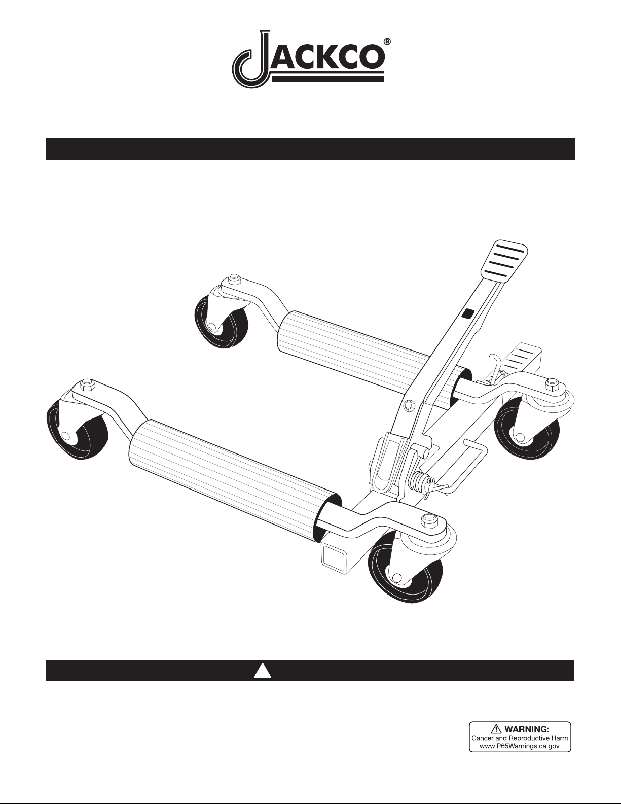
CD310 - 1500 LB Car Positioning Dolly
Owners’s Manual & Safety Instructions
WARNING
!
Read this material before using this product. Failure to do so can result in serious injury. SAVE THIS MANUAL.
Visit our website at: http://www.jackco.com
Email our technical support at: [email protected]
Page 2
WARNING SYMBOLS AND DEFINITIONS
This is the safety alert symbol. It is used to alert you to potential
personal injury hazards. Obey all safety messages that
follow this symbol to avoid possible injury or death.
Indicates a hazardous situation which, if not avoided,
will result in death or serious injury.
Indicates a hazardous situation which, if not avoided,
could result in death or serious injury.
Indicates a hazardous situation which, if not avoided,
could result in minor or moderate injury.
Addresses practices not related to personal injury.
IMPORTANT SAFETY INFORMATION
Failure to heed these markings may result in personal injury and/or property damage:
1. Study, understand, and follow all instructions
before operating this device.
2. Do not exceed rated capacity.
3. Use only on hard, level surface.
4. Before moving a load, assure that the load is
centered and secured with a load restraint device.
5. No alterations shall be made to this product.
6. Wear ANSI-approved safety goggles and
heavy-duty work gloves during use.
7. Keep clear of load’s path while placing on and
removing from dollies, and while moving.
8. Use as intended only. Do not use for
aircraft purposes. Use only in pairs.
9. Inspect before every use; do not use
if parts are loose or damaged.
10. Be aware of dynamic loading! Sudden
load movement may briefly create excess
load causing product failure.
11. Assemble only according to these instructions.
Improper assembly can create hazards.
12. Keep your work area clean and well lit.
Cluttered work areas invite accidents.
13. Keep bystanders, children, and visitors away
while operating Wheel Dolly. Distractions
can cause you to lose control.
14. Stay alert. Watch what you are doing, and
use common sense when operating Wheel
Dollies. Do not use while tired or under the
influence of drugs, alcohol, or medication. A
moment of inattention while operating Wheel
Dollies may result in serious personal injury.
15. Before use, read manufacturer’s instruction
manual for the vehicle you will lift.
16. Keep clear of load while lifting and lowering.
17. Do not work under vehicle while on Dollies.
18. Lower load slowly.
19. Weight capacity and other product capabilities apply
to properly and completely assembled product only.
20. Store idle Wheel Dollies out of reach of children
and other untrained persons. Jacks are
dangerous in the hands of untrained users.
21. Wheel Dolly service must be performed
only by qualified repair personnel. Service
or maintenance performed by unqualified
personnel could result in a risk of injury.
22. When servicing a Wheel Dolly, use only identical
replacement parts - refer to attached, product-specific
parts list and diagram. Follow instructions in the
“Inspection, Maintenance, And Cleaning” section of
this manual. Use of unauthorized parts or failure to
follow maintenance instructions may create a risk
of injury and may void any applicable warranty.
23. Industrial applications must follow
OSHA requirements.
Page 3
24. Do not allow anyone in the vehicle while using
the Wheel Dolly. Do not start the vehicle while
it is on Wheel Dollies. Keep all bystanders
a safe distance away from the vehicle.
26. Maintain product labels and nameplates.
These carry important safety information.
If unreadable or missing, contact
Jackco for a replacement.
25. This product is not a toy. Do not allow
children to play with or near this item.
SAVE THESE INSTRUCTIONS.
27. The warnings, precautions, and instructions
discussed in this manual cannot cover all possible
conditions and situations that may occur. The
operator must understand that common sense and
caution are factors, which cannot be built into this
product, but must be supplied by the operator.
Specifications
Rated Capacity 1500 lb
Maximum Tire Width 12.8″
Setup - Before Use:
Read the ENTIRE IMPORTANT SAFETY INFORMATION section at the beginning of this
manual including all text under subheadings therein before set up or use of this product.
Note: For additional information regarding the parts listed in the following pages,
refer to Parts List and Assembly Diagram
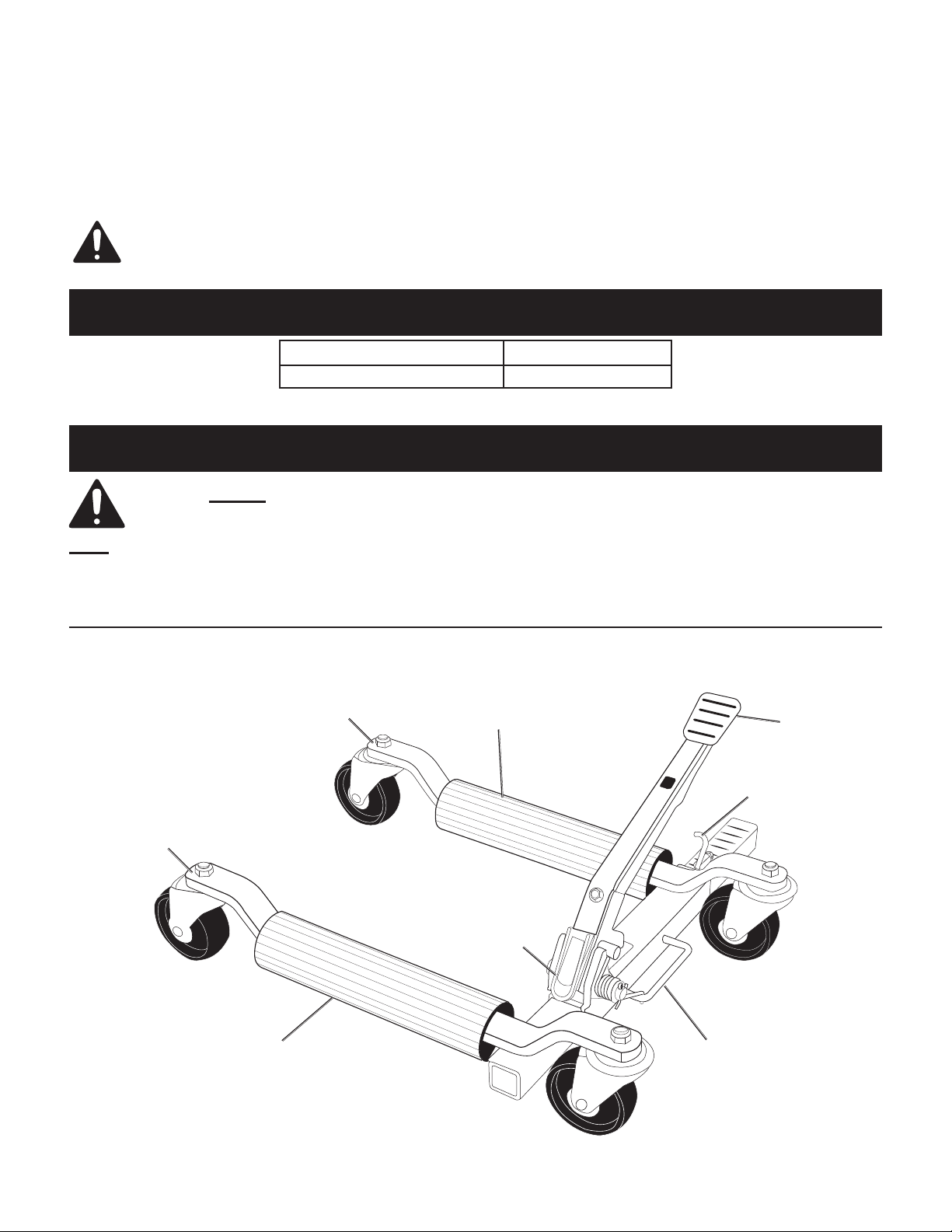
Functions
Left
Arm
Roller
Right
Arm
Roller
Lever
Foot
Pedal
Pedal
Lock
Handle
Figure A
Page 4
Assembly Instructions
Read the ENTIRE IMPORTANT SAFETY INFORMATION section at the beginning of this document
including all text under subheadings therein before set up or use of this product.
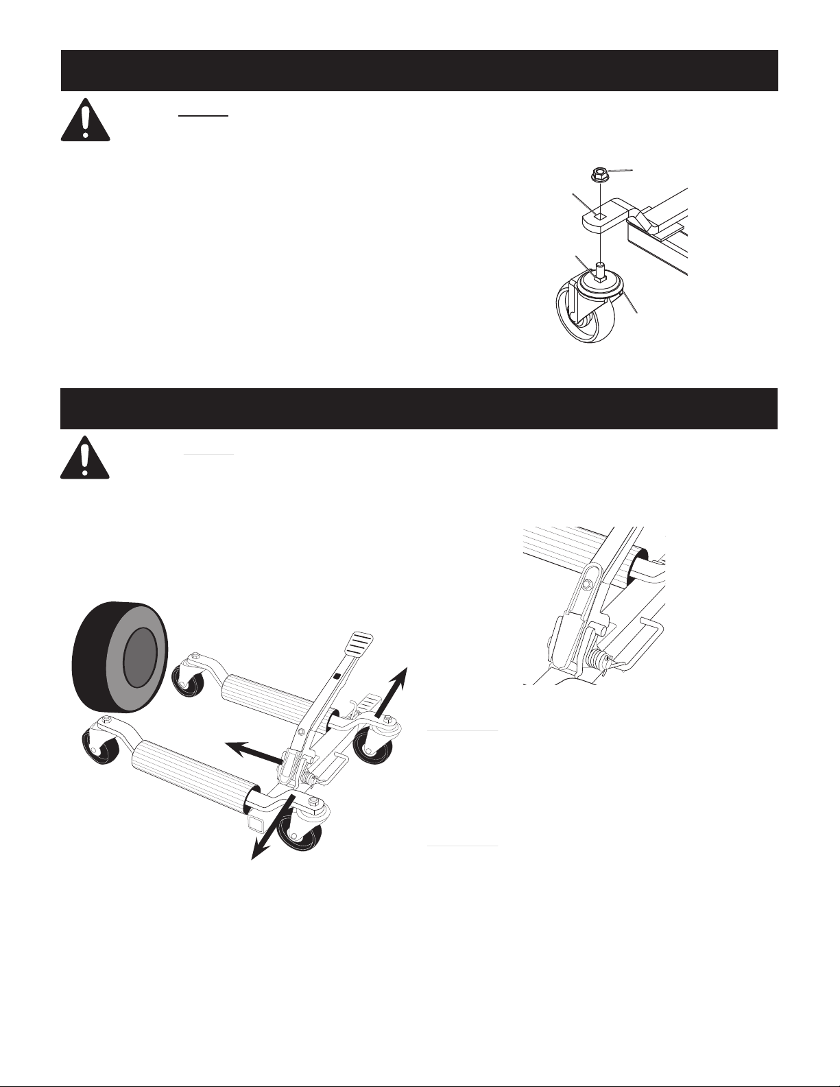
1. Assemble on a flat, level, hard and smooth surface.
2. Attach Casters, making sure the Square
Nuts seat inside the Square Openings.
3. Thread Lock Nuts on to Caster bolts, securing tightly.
Operating Instructions
Read the ENTIRE IMPORTANT SAFETY INFORMATION section at the beginning of this
manual including all text under subheadings therein before set up or use of this product.
1. Release the Foot Pedal by depressing it
and disengaging the Pedal Lock.
2. Lifting Tire:
a. With the Lever in the down position, roll Dolly in
front of tire, spread Arms apart, then push Dolly
forward so that Rollers are on either side of tire.
Square
Opening
Square
Nut
Figure B
b. Move the Lever to the up position, then pump the
Foot Pedal until the tire is just lifted off the ground.
Lock
Nut
Caster
Figure C: Putting Dolly Around Tire
(Lever in Down Position)
Figure D: Lever in Up Position
WARNING! Be ready for any movement the vehicle
may make when the other tire(s) come off the ground.
Ensure that you have sufficient assistance and
manpower to safely guide and control the vehicle.
3. Repeat 2. Lifting Tire: for the other
tire(s). Use only in pairs.
WARNING! Stay clear of any sloping areas or entry
ramps, however shallow they may appear. Sufficient
space should be allowed between the side of the
vehicle and an adjacent wall for the vehicle to be
withdrawn from its location in a sideways manner.
4. Lowering Tire:
a. Move the Lever to the down position, then
depress and release the Foot Pedal.
b. Once tire is on the ground, spread
Arms and remove Dolly.
c. Push arms together, then depress Foot Pedal
all the way and secure with Pedal Lock.
Page 5

Inspection, Maintenance, And Cleaning
Procedures not specifically explained in this manual must
be performed only by a qualified technician.
TO PREVENT SERIOUS INJURY FROM TOOL FAILURE:
Do not use damaged equipment. If abnormal noise or vibration
occurs, have the problem corrected before further use.
1. BEFORE EACH USE, inspect the general
condition of the Wheel Dolly. Check for:
• broken, cracked, or bent parts,
• loose or missing parts,
• and any condition that may affect the
proper operation of the product.
2. AFTER EVERY USE, wipe with a clean cloth. Then,
store the Wheel Dolly in a safe, dry location out of
reach of children and other non-authorized people.
3. PERIODICALLY:
• lubricate the Casters and
Foot Pedal pivot with oil.
• put Lever in down position, spread arms
apart and lightly grease the notched tube
.
Page 6
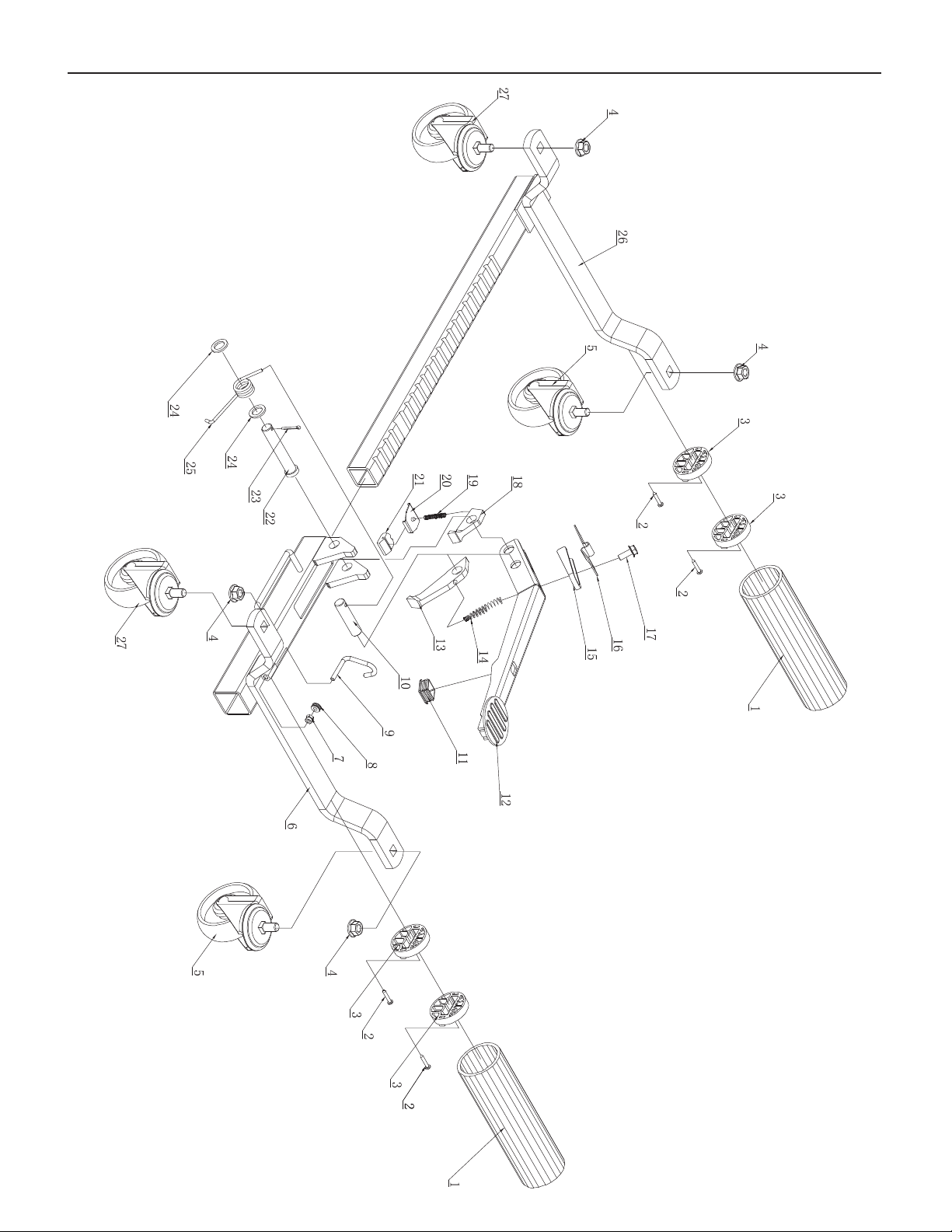
Assembly Diagram
Page 7
PLEASE READ THE FOLLOWING CAREFULLY
THE MANUFACTURER AND/OR DISTRIBUTOR HAS PROVIDED THE PARTS LIST AND ASSEMBLY DIAGRAM
IN THIS DOCUMENT AS A REFERENCE TOOL ONLY. NEITHER THE MANUFACTURER OR DISTRIBUTOR
MAKES ANY REPRESENTATION OR WARRANTY OF ANY KIND TO THE BUYER THAT HE OR SHE IS
QUALIFIED TO MAKE ANY REPAIRS TO THE PRODUCT, OR THAT HE OR SHE IS QUALIFIED TO REPLACE
ANY PARTS OF THE PRODUCT. IN FACT, THE MANUFACTURER AND/OR DISTRIBUTOR EXPRESSLY
STATES THAT ALL REPAIRS AND PARTS REPLACEMENTS SHOULD BE UNDERTAKEN BY CERTIFIED AND
LICENSED TECHNICIANS, AND NOT BY THE BUYER. THE BUYER ASSUMES ALL RISK AND LIABILITY
ARISING OUT OF HIS OR HER REPAIRS TO THE ORIGINAL PRODUCT OR REPLACEMENT PARTS
THERETO, OR ARISING OUT OF HIS OR HER INSTALLATION OF REPLACEMENT PARTS THERETO.
Parts List and Assembly Diagram
Parts List
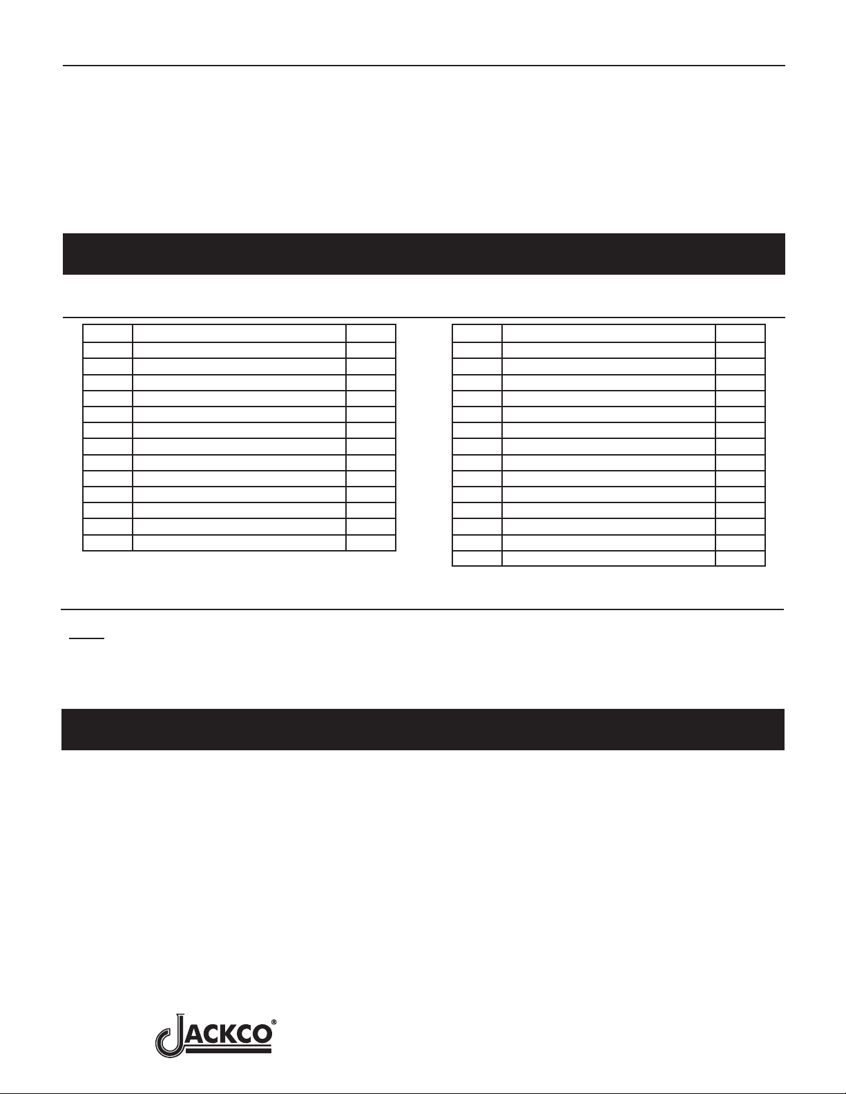
Part Description Qty
1 Roller 2
2 Screw (4.2x25) 4
3 Roller Bearing 4
4 Lock Nut (M12) 4
5 4” Caster 2
6 Right Arm 2
7 Lock Nut (M6) 1
8 Rubber Ring 1
9 Pedal Lock 1
10 Retaining Pin 2 1
11 Square Plug 1
12 Pedal 1
13 Front Pawl 1
Note: Some parts are listed and shown for
illustration purposes only, and are not available
individually as replacement parts.
Limited One Year Warranty
Part Description Qty
14 Spring 1
15 Lever 1
16 Spring Pad 1
17 Screw (M8x22) 1
18 Back Pawl 1
19 Spring 1
20 Plate 1
21 Retainer 1
22 Retaining Pin 1 1
23 Cotter Pin (Ø3x30) 1
24 Washer 2
25 Torsion Spring 1
26 Left Arm 1
27 4.9” Caster 2
Jackco Transnational Inc. (Jackco) warrants all Jackco equipment and tools to the original purchaser against any
manufacturing defect in material or workmanship for a period of one (1) year from the original date of purchase. If the
defective equipment or tool is determined to be covered under this warranty, it shall be repaired or replaced at
manufacturer's discretion without charge, provided that the equipment or tool must be returned with proof of
purchase to the dealer and freight prepaid, if returned to the manufacturer. This warranty shall not apply to damage
due to accident, negligent use, lack of maintenance, abuse or applications other than the specific function the
equipment or tool is designed for.
No other warranties, expressed or implied, including those of merchantability or fitness for particular purpose shall
be applicable to Jackco except as specifically stated herein. In no event shall Jackco be liable to any party for any
special, direct, indirect, consequential, punitive damage of any nature caused by the sale or use of the equipment or
tool.
Note: This warranty gives the original purchaser specific legal rights which may very from state to state.
Visit our website at: http://www.jackco.com
Email our technical support at: [email protected]
 Loading...