

Page 1
Page 2

LIMITED ONE YEAR WARRANTY
Jackco Transnational Inc. warrants all Jackco equipment and tools to the original purchaser
against any manufacturing defect in material or workmanship for a period of one (1) year from
the original date of purchase. If the defective equipment or tool is determined to be covered
under this warranty, it shall be repaired or replaced at manufacturer's discretion without charge,
provided that the equipment or tool must be returned with proof of purchase to the dealer and
freight prepaid, if returned to the manufacturer. This warranty shall not apply to damage due to
accident, negligent use, lack of maintenance, abuse or applications other than the specific
function the equipment or tool is designed for.
No other warranties, expressed or implied, including those of merchantability or fitness for
particular purpose shall be applicable to Jackco except as specifically stated herein. In no
event shall Jackco be liable to any party for any special, direct, indirect, consequential,
punitive damage of any nature caused by the sale or use of the equipment or tool.
Note: This warranty gives the original purchaser specific legal rights which may very from state
to state.
1
Page 3

WARNING
• All WARNING statements must be carefully
observed to help prevent personal injury.
• Do not exceed rated capacity.
• All devise used must be rated for the same
maximum operating pressure, correctly connected
and compatible with the hydraulic fluid used. An
improperly matched system can cause the system to
fail and possibly cause serious injury.
• Use only on hard, level surfaces capable of
sustaining rated capacity loads.
• For safety, operate equipment at least 6 feet
from either side of post and chains.
• Do not stand behind post, chain and clamps
when under load.
• Do not use the safety chain under floating
pulley as a "pull" chain.
• On severe pulls, use secondary safety ties
and/or tarps and blankets around chains.
• Do not pull chain over sharp corners. Use
protective pads.
• Listen for popping noises indicating weld
fractures and possible sudden separation.
• Avoid sudden jerks when applying tension to
chain.
• Wear protective clothing and safety goggles
to reduce the risk of injection.
• Do not wear sandals and jewelry when
operating this equipment.
• Never use chain assemblies not intended for
collision repair equipment.
• The chain/hooks must be 3/8" trade size,
heat treated, alloy type rated for "collision repair"
applications.
• Do not cut chain with cutting torches. Heat
will degrade chain.
• Remove damaged, kinked, twisted, stretched
or rusty chain from service so it cannot be
accidentally reused.
• Monitor pressure and load at all times.
• Always verify load with calibrated load cell
and indicator, known good pressure gauge or
equivalent devices.
• As the load is lifted, use blocking and
cribbing to guard against a falling load.
• Never allow personnel to work on, under or
around a load before it is properly supported by
appropriate mechanical means. Never rely on
hydraulic pressure alone to support load.
• All personnel must be clear before lowering.
• Never try to disassemble a ram or pump.
Refer repairs to qualified, authorized personnel.
• Do not modify this device.
• When the ram is not is use, keep ram fully
retracted.
• Failure to heed these markings may result in
personal injury and/or property damage.
• Never operate pump with release valve closed and
disconnected from application. If operated in this condition,
the hose and connections become pressurized. This
increases burst hazard. Damage may occur to pump and
its components
• Avoid short runs of straight line tubing. Straight
line runs do not provide for expansion and contraction due
to pressure and/or temperature changes.
• Reduce stress in tube lines. Long tubing runs
should be supported by brackets or clips. Before operating
the pump, all hose connections must be tightened with the
proper tools. Do not over tighten. Connections should only
be tightened securely and leak-free. Over tightening can
cause premature thread failure or high pressure fittings to
burst.
• Should a hydraulic hose ever rupture, burst or
need to be disconnected, immediately shut off the pump
and release all pressure. Never attempt to grasp a leaking
pressurized hose with your hands. The force of escaping
hydraulic fluid can inflict injury.
• Do not subject the hose to potential hazard such
as fire, sharp objects, extreme heat or cold or heavy
impact.
• Do not allow the hose to kink, twist, curl, cr ush, cut
or bend so tightly that the fluid flow within the hose is
blocked or reduced. Periodically inspect the hose for wear,
because any of these conditions can damage the hose and
possibly result in personal injury.
• Do not pull, position or move setup by the hose.
Doing so can damage the hose and possibly cause
personal injury.
• Hose material and coupler seals must be compatible with hydraulic fluid used. Hoses also must not come in
contact with corrosive materials such as battery acid,
creosote-impregnated objects and wet paint. Hose
deterioration due to corrosive material can result in
personal injury. Never paint a coupler or hose.
• Use only approved accessories and approved
hydraulic fluid.
• To help prevent material fatigue if the ram is to be
used in a continuous application, the load should not
exceed 85% of the rated capacity.
• Use an approved, high-grade pipe thread sealant
to seal all hydraulic connections. Teflon tape can be used
if only one layer of tape is used and it is applied carefully
(two threads back) to prevent the tape from being
introduced into hydraulic system. A piece of tape could
travel through the system and obstruct the flow of fluid and
adversely affect function.
2
Page 4
PRODUCT DESCRIPTION
Power Post is designed for the rated capacity lifting and pulling jobs. This power post can shall used
with common pot patterns. Operator can create their own custom pull system. A wide variety of
applications exist for this category of product. Special skill, knowledge and training may be required for
a specific task and the product may not be suitable for all the jobs described above. Unsuitable
applications would include applications that call for a device to move, level or support persons, animals,
hazardous materials, mobile homes/ dwellings in general, mirrors and/or plate glass, and/or to
connect/secure hatches, components, etc. between bulkheads. The user must ultimately make the
decision regarding suitability of the product for any given task and assume the responsibility of safety for
him and others in the work area.
SPECIFICATIONS
Power Post Frame Ram
Model Capacity
Height
892 10 ton 68.5" 33" x 16" 12 8"
Base Size
( L x W)
Floating
Pulley
Position
Stroke
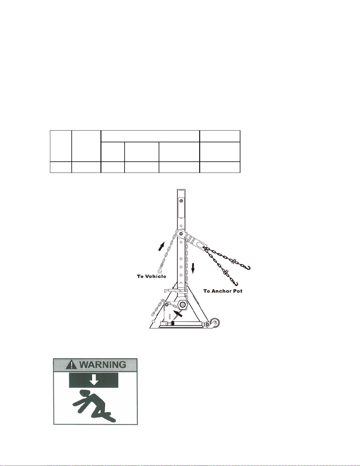
Figure 1 – Chain Routing Instruction
If oil leakage is detected, discontinue use of the
ram immediately. The ram could develop excessive
pressure and cause the ram, hose or coupler to burst
which could cause serious injury or death.
When loading a ram, always insure that coupler,
port, and adapter threads have not been damaged.
Failure to do so could cause serious injury or death.
3
Page 5
SET UP
Suggestion: install a pressure gauge (not included) on your pump to indicate a relative level of pulling
force.
1. Secure the thread ed ram to bottom of power post, then connect ram to air pump with hydraulic hose
provided.
2. Slide the pull chain thru the chain pulley, idle pulley and power lever arm.
3. Secure the safety chain on chai n pulley to an anchor pot.
Note: The dual chain helps to divide the pull force exerted by the post and also allows positioning the
post between two anchor pots.
OPERATION
Safety Message! Operate equipment from at least 6 feet from either side of post and chains.
1. Adjust the chain pulley (# 21) to desire height to pull using the handle bar.
2. Secure the pull chain before pulling object.
3. To operate, activate air pump or use the hand pump until desire height or position is reached. Always
monitor pressure and load. Use caution when nearing this maximum operating ram pressure.
Caution! Never operate pump with release valve closed and di sconnected from ram. If operated in this
condition, the hose and connections become pressurized. This increases burst hazard. Damage may
occur to pump and its components
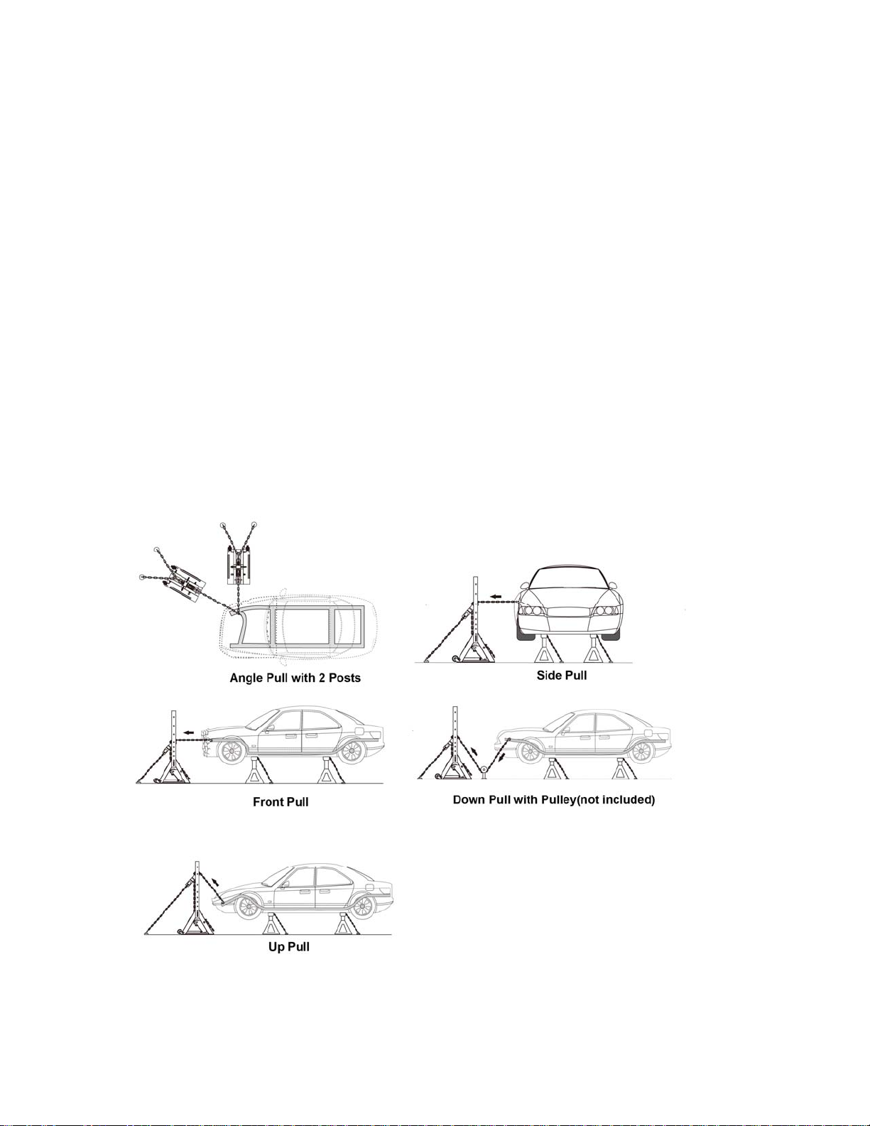
Figure 2 - Illustrations of Common Applications
4
Page 6
MAINTENANCE
1. Inspect and replace dama ged, kinked, twisted, stretched or rusty chain.
2. Inspect hoses and con nections. Replace damage components immediately with Jackco
replacement parts only.
3. Tighten connections as needed. Use non-hardening pipe thread compound when servicing
connections.
4. Use only good quality hydraulic fluid. We recommend Jackco Model 0101 0 Hydraulic Oil or
equivalent.
Lubrication
Use a light machine oil to lubricate pivot points, hinges and all joints of post that move under heavy load.
Storage
1. Depressurize and disconnect hydraulic hoses from ram.
2. Wipe clean and store in dry environment. Avoid extreme temperatures.
TROUBLESHOOTING
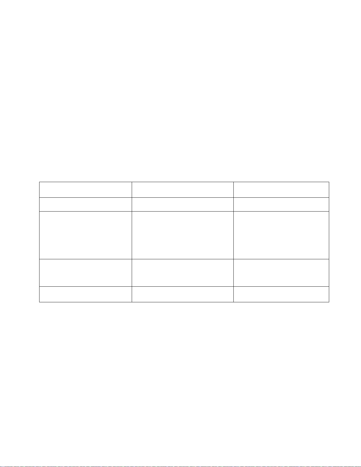
Symptom Possible Causes Correct Action
System does not maintain
pressure
Ram does not return fluid to
pump(i.e. ram will not retract)
Poor performance
Will not lift to full extension • Fluid level low • Ensure proper fluid level
• Hydraulic unit malfunction
• Reservoir overfilled
• Ram damaged
• Malfunctioning coupler, damaged
application
• Fluid level low
• Air trapped in system
• Replace or repair ram and / or
pump
• Drain fluid to proper level
• Replace Ram
• Secure load by other means.
• Depressurize pump and hose,
remove coupler and/ or
application, and then replace with
a new one.
• Ensure proper fluid level
• With ram fully retracted, remove
oil filler screw to let pressurized
air escape.
5
Page 7
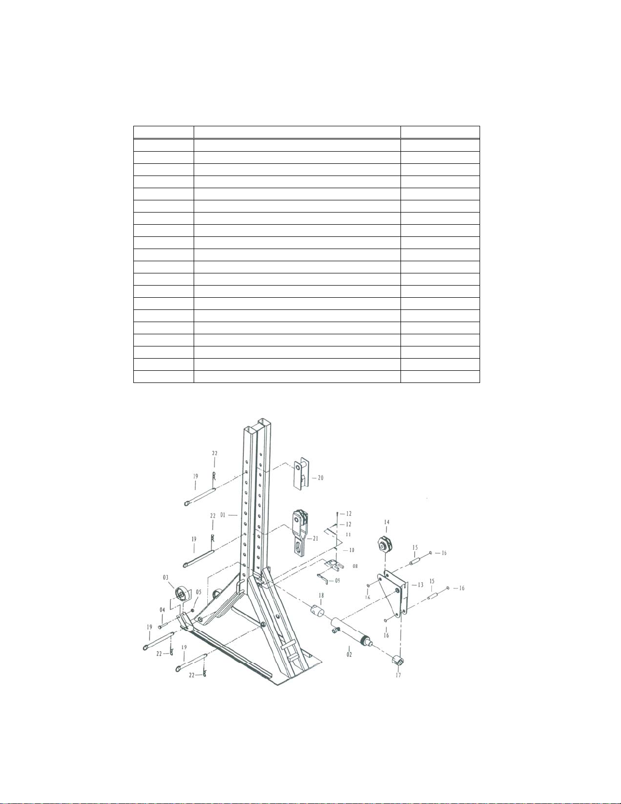
PARTS LIST
Please refer to the Parts drawing when ordering parts. Not all components are replacement items, but
are illustrated as a convenient reference of location and position in the assembly sequence. When
ordering parts, please give model no., and description below. Call or write for current pricing: Jackco
Transnational Inc. South El Monte, CA 91733 TEL: (626)582-8055 or visit us at www.jackco.com
Part # Description Qty
01 Frame 1
02 10 Ton Ram 1
03 Wheel 2
04 Hex Head Screw (3/8” x 2- 9/16”) 2
05 Hex Head Nut (3/8) 2
08 Lock Plate 1
09 Stop Plate 1
10 Spring 1
11 Chain 1
12 Inner Hex Screw (3/16 x ¾”) 2
13 Lever Arm 1
14 Swivel Castor 1
15 Pin 2
16 Snap Ring “C” 4
17 Female Adapter (Snap) 1
18 male Adapter (Snap) 1
19 Spindle 4
20 Secondary Anchor 1
21 Chain Pulley 1
22 Spring Hair Pin Clip 4
Replacement Parts Illustration for Model 892
6
 Loading...