

Page 1
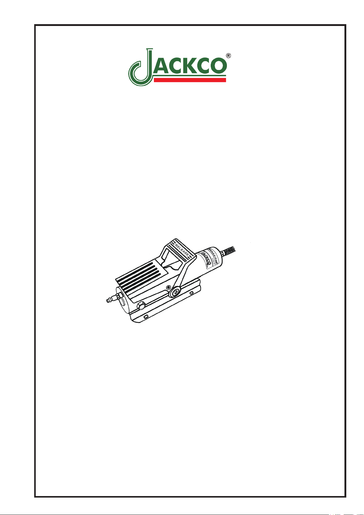
MODEL 840
AIR HYDRAULIC PUMP
INSTRUCTION
Jackco Transnational Inc. © 2012
South El Monte, CA
888-452-2526 www.jackco.com
Page 2
FOR YOUR SAFETY
Read all instructions, warnings and cautions carefully. Follow all safety precautions to avoid personal injury
or property damage during system operation. Jackco cannot be responsible for damage or injury resulting
from unsafe product use, lack of maintenance or incorrect product and/or system operation. Contact Jackco
when in doubt as to the safety precautions and operations.
Failure to comply with the following cautions and warnings could cause equipment damage and personal
injury.
• Stay clear of loads supported by hydraulics.
A cylinder, when used as a load lifting device,
should never be used as a load holding device.
After the load had been raised or lowered,
it m u s t al w a y s be b locked m e chanicall y.
• Do not exceed equipment rating never attempt
to lift a load weighing more than the capacity
of the cylinder. Overloading causes equipment
failure a n d possible personal i n j u r y. The
cylinders are designed for a maximum pressure
of 10,000 psi. Do not connect a jack or cylinder
to a p ump w i t h a h i g h e r p r e s s u r e rating.
• The system o p e r a t i n g pressure m u s t not
exceed the pressure rating of t h e lowest
ra t e d c o m po ne n t in th e sys t e m . Ins t al l
pressur e gaug es in the system to m onitor
o p e r a t i n g pr e s s u r e . It is yo u r wi n d o w
t o w h a t i s h a p p e n i n g i n th e s y s t e m .
• Onl y use hyd raulic c ylinde rs in a cou pled
s y s t e m . N e v e r u s e a c y l i n d e r w i t h
unconnected couplers. If the cylinder becomes
extremely overloaded, components can fail
catastrophically causing severe personal injury.
• BE S U R E SET U P IS STA B L E BE FO RE
LIFTING LOAD.
Cy l i n d e r s sh o u l d be pl a c e d on a fl a t
sur f ace that can supp ort the load . Where
applicab le, use a cylin der bas e for added
stability. Do not weld or otherwise modify the
cylinder to attach a base or other support.
• Avoid situations where loads are not directly
centered on the cylinder plunger. Off-center
loads produce considerable strain on cylinders
and plungers. In addition, the load may slip
or fall, causing potentially dangerous results.
• To avoid personal injury keep hands and feet away
from cylinder and work piece during operation.
• NEVER set the relief valve to a higher pressure
than the maximum rated pressure of the pump.
Higher settings may result in equipment damage
and/or personal injury. Do no remove relief valve.
• Do not handle pressurized hoses. Escaping oil
under pressure can penetrate the skin, causing
serious injury. If oil is injected under the skin, see a
doctor immediately.
• Avoid damaging hydraulic hose. Avoid sharp bends
and kinks when routing hydraulic hoses. Using a
bent or kinked hose will cause severe backpressure.
Sharp bends and kinks will internally damage the
house leading to premature hose failure.
• Do not drop heavy objects on hose.
A sharp impact may cause internal damage to hose
wire strands. Applying pressure to a damaged hose
may cause it to rupture.
• Do not lift hydraulic equipment by the hoses or
swivel couplers. Use the carrying handle or other
means of safe transport.
• Keep hydraulic equipment away from flames and
heat. Excessive heat will soften packing and seals,
resulting in fluid leaks. Heat also weakens hose
materials and packings. For optimum performance
do not expose equipment to temperatures of 150°F
or higher. Protect hoses and cylinders from weld
spatter.
• Immediately replace worn or damaged parts
genuine JACKCO parts. Standard grade parts
will break causing personal injury and property
damage. JACKCO parts are designed to fit
properly and withstand high loads.
• Hydraulic equipment must only be serviced by a
qualified hydraulic technician. For repair service,
contact JACKCO Inc. To protect your warranty, use
only JACKCO hydraulic oil.
Page 3
INSTRUCTION
BEFORE USING THE PUMP
• Check all system tting and connections to be sure they are tight and leak free.
• Check oil level in reservoir before operating pump.
TO OPERATE THE PUMP
• Remove the shipping plug from the air inlet hole and insert a ¼” NPT quick air coupler of
your choice.
• Connect air supply line to the air coupler.
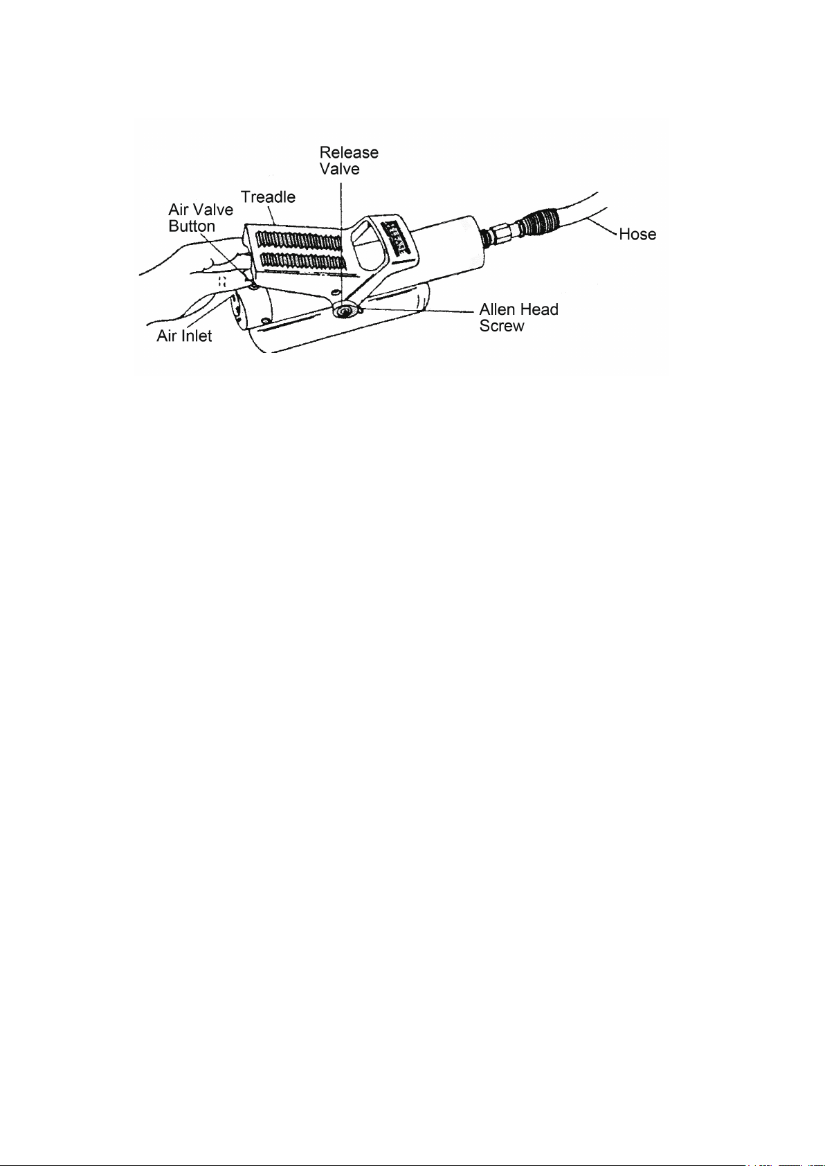
• To activate the pump for ram extension, depress the treadle at air inlet valve end.
• To retract ram plunger, depress treadle end marked “RELEASE”. Retraction of ram will
stop and load will be held when pressure on treadle is removed.
AIR REMOVAL
Removing air from the hydraulic system will help the cylinder to advance and retract smoothly.
Pump with Single-Acting Cylinder
• Position pump at higher elevation than cylinder.
• Position cylinder with plunger end down (up if using pull cylinder)
• Operate pump to fully extend the cylinder (retract if using pull cylinder)
• Depress release valve to retract cylinder (extend if a pull cylinder). This will force the
trapped air to move up to the pump reservoir.
• Repeat the above steps as necessary.
• Add oil if necessary.
• Return vent/ll cap to operating position.
TO ADD OIL TO PUMP RESERVOIR
• Turn pump upside down and remove hex ller plug. Tip pump so the hose end is lowest
to prevent air from entering the hydraulic system. Fill to the top with HYDRAULIC oil.
Replace ller plug and tighten rmly. Do not use brake uid nor transmission oil.
Page 4

AIR SUPPLY
• To obtain maximum performance and rated hydraulic pressure, air pressure should be 100
psi minimum.
• To insure trouble-free performance, your air supply equipment should be equipped with an air
lter/dryer and the compressor tank should be drained of water everyday.
LUBRICATION
• To insure long service life, add a few drops of # 30 oil into the air inlet once a week.
RELEASE VALVE ADJUSTMENT PROCEDURE
• Attach pump to its air source.
• Turning counterclockwise to loosen Allen-head screw by two full turns.
• Turning counterclockwise back out slotted-head release valve two full turns.
• Lift treadle at air inlet end and place your thumb under the treadle on top of the air valve
button as illustrated.
• Using your thumb press down on the air valve button and actuate the pump to build up
pressure in the hose. Hose will become stiff under pressure.
• Turn slotted-head release valve clockwise gently until you feel the valve seat against the
internal ball. Excessive tightening will cause loss of pressure in hose.
• Keep the thumb under treadle to obtain proper operating clearance between the treadle, air
valve and release valve. Turn Allen-head screw clockwise and tighten rmly to lock valve
adjustment.
• Release valve should now be correctly adjusted to operate the pump properly.
MAINTENANCE
Use only recommended JACKCO hydraulic oil with theses pumps to promote long pump life
and protect your warranty. Contact your JACKCO representative for more information on these
products and their applications.
KEEPING OIL LINES CLEAN
When coupler halves are disconnected, always screw on dust caps. Use every precaution to
guard unit against entrance of dirt because foreign matter may cause pump, cylinder or valve
failure.
CHANGING THE OIL
• Drain all oil and rell with clean JACKCO hydraulic oil every 12 months, if pump is used in
dirty environments, change the oil more often.
• Remove vent/ll cap or plug from reservoir
• Tilt pump to drain out old oil.
• Fill reservoir only to level mark shown on pump
• Replace the vent/ll cap or plug.
• Dispose of used oil properly.
Page 5

TROUBLESHOOTING
Problem Possible Cause Solution
Cylinder does not
advance, advances
slowly, or advances in
spurts.
1. Oil level in pump reservoir is
low.
2. Release valve open.
3. Loose hydraulic coupler.
4. Load is too heavy.
5. Air trapped in system.
6. Cylinder plunger binding.
1. Add old according the maintenance
instructions.
2. Close the release valve.
3. Check that all couplers are fully tightened.
4. Do not attempt to lift more than rated
tonnage.
5. Remove air according to the instructions.
6. Check for damage to cylinder. Have
cylinder serviced by a qualied hydraulic
technician.
Cylinder advance,
but does not hold
pressure.
Cylinder does not
retract, retracts part
way, or retracts more
slowly than normal.
1. Leaking connection.
2. Leaking seals.
3. Internal leakage in pump.
1. Pump reservoir is over-lled
2. Loose hydraulic coupler.
3. Air trapped in system.
4.Cylinder retraction spring
broken or other cylinder
damage.
1. Check that all connections are tight and
leak free.
2. Locate leak(s) and have equipment
serviced by qualied hydraulic technician.
3. Have pump serviced b y a qualified
hydraulic technician.
1. Drain oil level to ll mark.
2. Check that all couplers are fully tightened.
3. Remove air according to the instructions.
4. Have cylinder serviced by a qualified
hydraulic technician.
Page 6

Model: 840 Parts List
Page 7

1
04 Gasket
1
Part No. Description Q'ty Part No. Description Q'ty Part No. Description Q'ty
M01 Motor Body 1 M25A Coupling 1 P25 Washer 1
M02 Body with Sleeve 1 M26B Dust Cap 1 P26 Nut 1
M03 Pin 1 P01C Pump Base 1 P27 Adapter 1
M04 Vavle-stem 1 P02 Ball 5/16" 1 P28 Screw 1
M04-1 Seal Cap 1 P03 Spring 1 P30 Washer 1
M04-2 Spring 1 P04 Pump Cylinder 1 P31 Set Screw 1
M05 Seal Cap 1 P06B O-ring 1 P32 Washer 1
M06 Exhaust Plug 1 P07B Washer 2 P33 Bolt Check Valve 1
M07 O-ring 1 P08 Nut 1 P34 Washer 1
M08 Stem 1 P09 Ball 7/32" 2 P36 Steelball 3/16" 1
M10 Spring 1 P10 Spring 1 P37 Spring, Safety Valve 1
M11 Screw 1 P11 O-ring 1 P38 Spring Safety 1
M12 Plug 1 P12 Check Valve 1 P39 Spring O-ring 1
M13 Spring 1 P13 O-ring 1 P40 Screw Safety Valve 1
M14 Ball 9/23" 1 P14 O-ring 1 P41 Plastic Cap Safety Valve 1
M15 Seal Washer 1 P15 Release Valve 1 01 Treadle 1
M16 O-ring 1 P16B Seal 1 02 Spring Hook Washer 1
P18 Ring Retaninig
1
M17 Stem 1 P17 Release 1 03 Spring 1
M18 O-ring
M19 Plug 1 P19 Filter 2 05 Allen Head Screw 1
M20 Piston Ring 1 P20 Washer 1 06 Allen Head Screw 4
M21 Piston 1 P21 Screw 1 07 Base 1
M22 Plunger 1 P22B Hydraulic Pipe 1 12 Silencer Bolt 2
M23 Cap Washer 1 P23B Oil Reservoir 1
M24 Spring 1 P24B Reservoir 1
Page 8

LIMITED ONE YEAR WARRANTY
Jackco Transnational Inc. warrants all Jackco equipment and tools to the original purchaser against any manufacturing defect in material or
workmanship for a period of one (1) year from the original date of purchase. If the defective equipment or tool is determined to be covered under
this warranty, it shall be repaired or replaced at manufacturer's discretion without charge, provided that the equipment or tool must be returned
with proof of purchase to the dealer and freight prepaid, if returned to the manufacturer. This warranty shall not apply to damage due to accident,
negligent use, and lack of maintenance, abuse or applications other than the specic function the equipment or tool is designed for.
No other warranties, expressed or implied, including those of merchantability or tness for particular purpose shall be applicable to Jackco
except as specifically stated herein. In no event shall Jackco be liable to any party for any special, direct, indirect, consequential, punitive
damage of any nature caused by the sale or use of the equipment or tool.
Note: This warranty gives the original purchaser specic legal rights which may very from state to state.
Jackco Transnational Inc. © 2012
South El Monte, CA
888-452-2526 www.jackco.com
 Loading...