

Page 1
MODEL 811
10 TON BODY AND FRAME
REPAIR KIT
USER'S MANUAL
Jackco Transnational Inc. © 2009
South El Monte, CA
888-452-2526 www.jackco.com
Page 2
FOR YOUR SAFETY
Read all instructions, warnings and cautions carefully. Follow all safety precautions to avoid personal injury
or property damage during system operation. Jackco cannot be responsible for damage or injury resulting
from unsafe product use, lack of maintenance or incorrect product and/or system operation. Contact Jackco
when in doubt as to the safety precautions and operations.
Failure to comply with the following cautions and warnings could cause equipment damage and personal
injury.
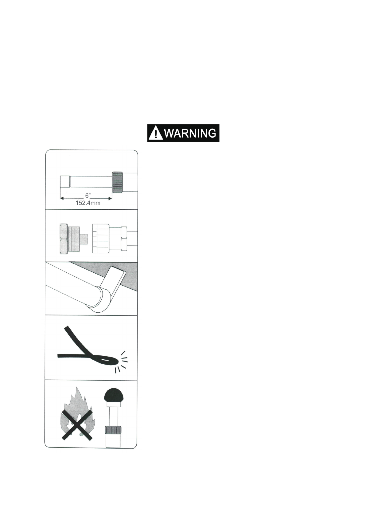
Ram Load
Never lift a load that exceeds the capacity of the ram.
Do not over extend the ram, because it is possible to
force the plunger out of the top of the ram.
Dust Caps
When coupler valves are disconnected screw in dust
cap to keep the oil line clean.
Off-center loads
Be careful when load is not centered on ram plunger.
Pump carefully- IF YOU FEEL THAT YOU HAVE TO
PUMP UNUSUALLY HARD-STOP. Adjust set-up to
the off center load is reduced.
Protect your hose
Do not drop heavy objects on your hose and avoid
sharp kinks. Provide proper clearance to avoid
damage to the hose and couplers.
Heat and re
Always keep your equipment away from excessive
heat or re.
Page 3
INSTRUCTION
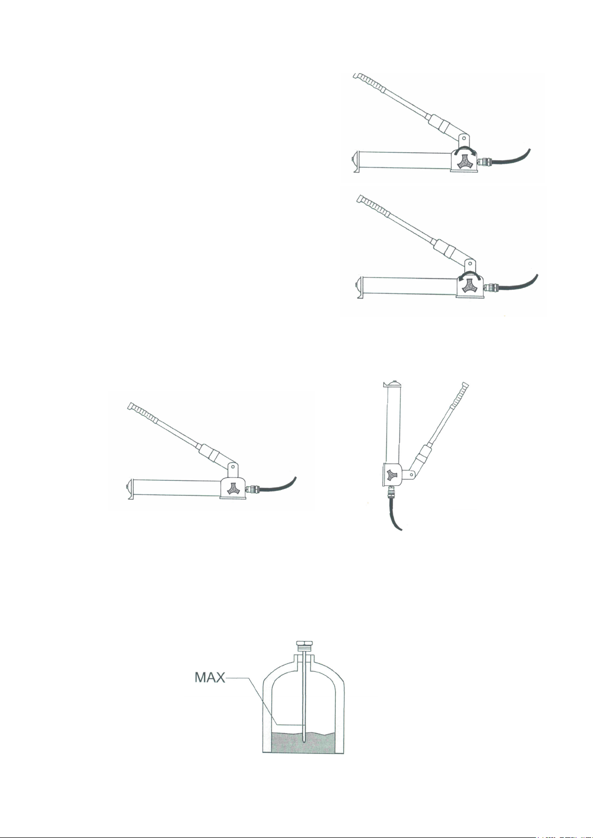
How to operate
Release Valve
Tur n knob C L O C K W ISE and pump han d l e for
applying pressure.
Turn knob counterclockwise to release pressure.
Pump Position
It is possible to hold pump in any possible from horizonal to vertical but always keep the
hose end of the pump down when above the horizontal position
Oil Level
Retract the ram that is connected to the pump. Place pump in an upright position as
shown. Remove ller plug and add hydraulic oil until it is level with the full mark on the dip
stick.
Page 4
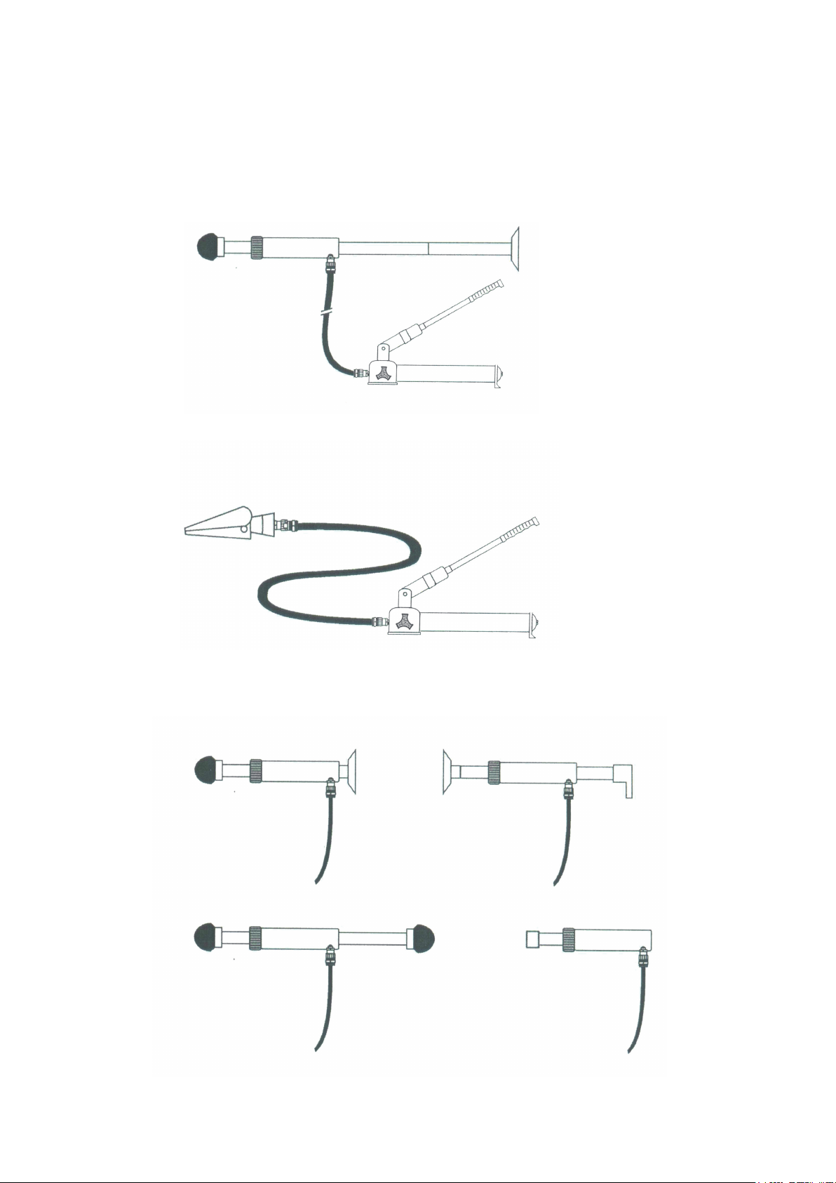
Set Up
Possible congurations for the 10 ton ram and attachments.
Rubber
Head
Spreader
Ram
Extension
Pump
Flat
Base
Rubber
Head
Rubber
Head
Ram
Ram
Flat
Base
Flat
Base
Rubber
Head
Pump
Ram
Serrated
Saddle
Spoon
Ram
Page 5
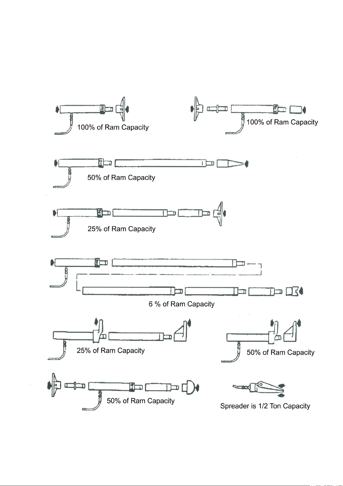
Load Capacities
The capacity of this equipment is signicant affected by the number of attachments used and
the type of load supplied several typical hook-ups are illustrated below. The approximate load
capacity if each set up is noted with illustration. When using two or more extension tubes
together, always position the shortest tube farthest away from the ram.
Page 6
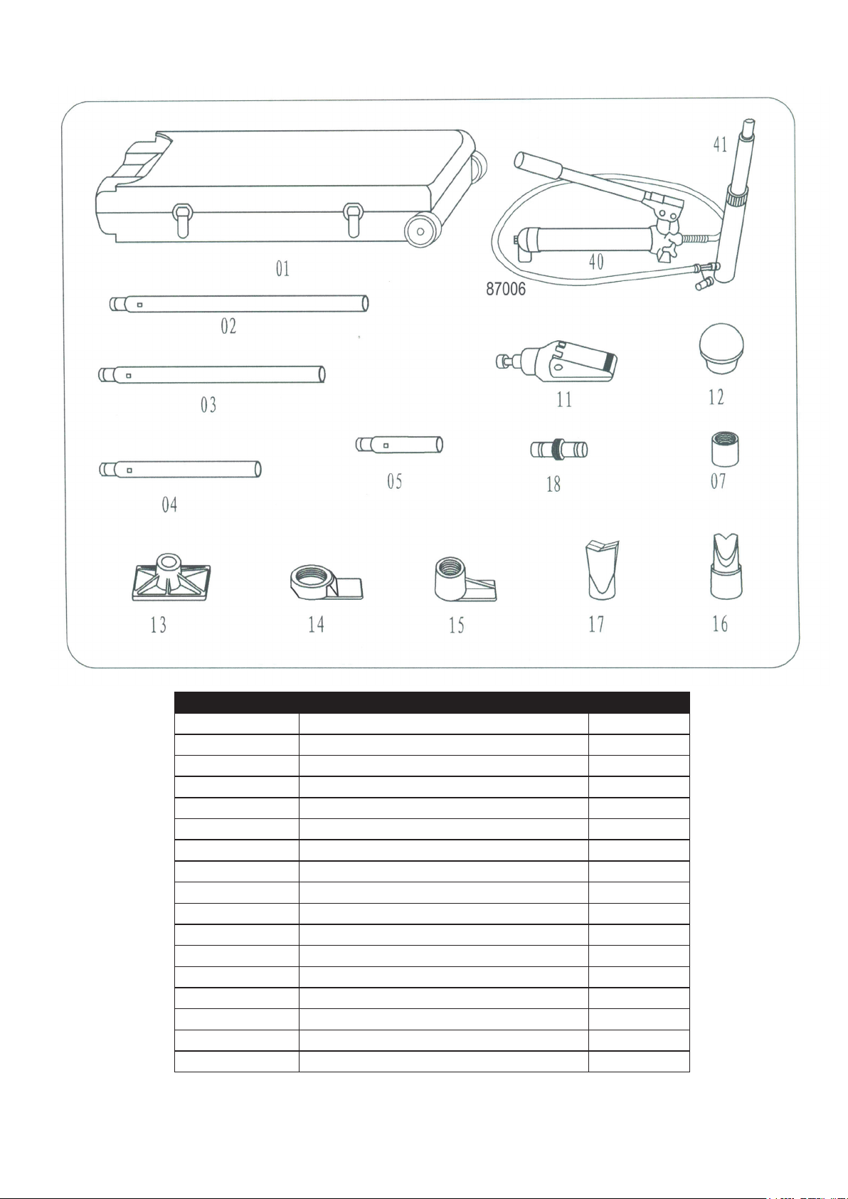
Parts List
Part No. Description Q'ty
811-01 Blow Mold Case 1
811-A02 24" Extension Tube 1
811-A03 21" Extension Tube 1
811-A04 10" Extension Tube 1
811-A05 5" Extension Tube 1
811-07 Serrated Saddle 1
811-11 Spreader Ram 1
811-12 3 1/4" Rubber Head 1
811-13 Flat Base 1
811-14 Spreader Ram Toe 1
811-15 Spreader Plunger Toe 1
811-16 Wedge Head 1
811-17 90° V-Base 1
811-18 Lock on Connector 1
811-40 10 Ton Hydraulic Unit 1
811-41 10 Ton, 6" Stroke Ram 1
87006 6 ft. Hose With Half Coulping 1
Page 7
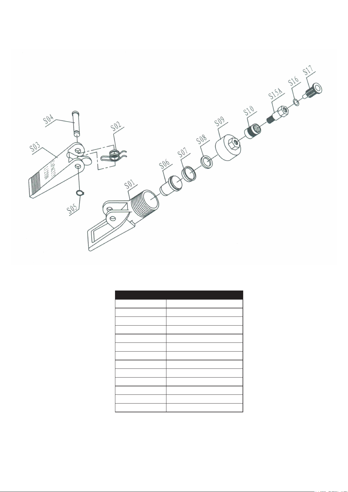
Hydraulic Spreader Assembly 1/2 Ton Capacity
Part No. Description
11-S01 Lower Duck Bill
11-S02 Spring
11-S03 Upper Duck Bill
11-S04 Pivoting Pin
11-S05 Cir Clips
11-S06 Piston
11-S07 Cup Seal
11-S08 Washer
11-S09 End Cap
11-S10 Coupling Ring
11-S15A Couping Bolt
11-S16 Bolt O-Ring
11-S17 Dust Cap
Page 8
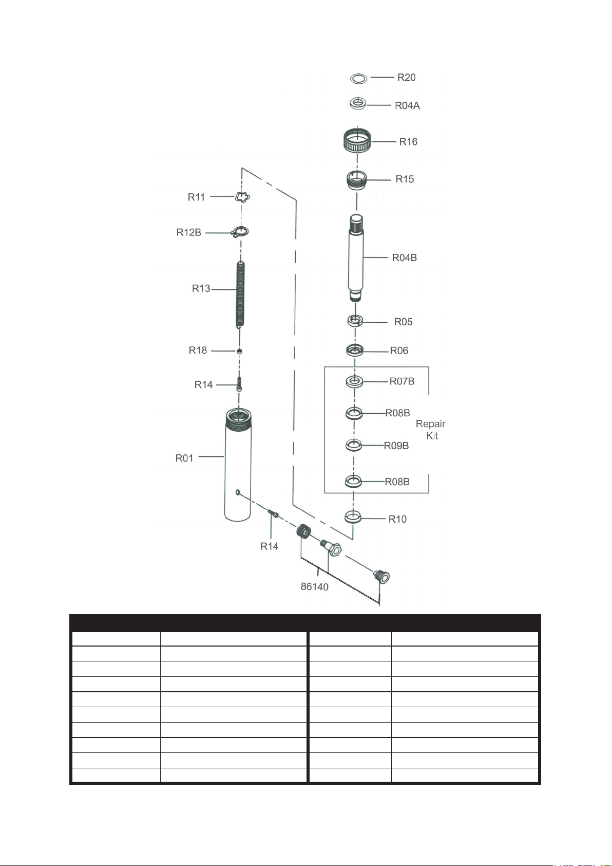
Hydraulic Ram Assembly 10 Ton Capacity
Part No. Description Part No. Description
811-R01 Cylinder 811-R12B Snap-Ring "C"
811-R04B Ram 811-R13 Spring
811-R04A Bearing 811-R15 Ring
811-R05 Bearing 811-R16 Protecting Cap
811-R06 Bushing 811-R14 Screw
811-R07B Cap Ferrule(C2600p) 811-R18 Bushing
811-R08B V Seal (Uletan) 811-R20 Ring "C"
811-R09B V Seal (SS400) 86140 1/4" hydraulic coupler
811-R10 Spreader
811-R11 Washer
Note: Model: 81041RK-Seal Repair Kit contains : 811-R07B, R08B, R09B
Page 9
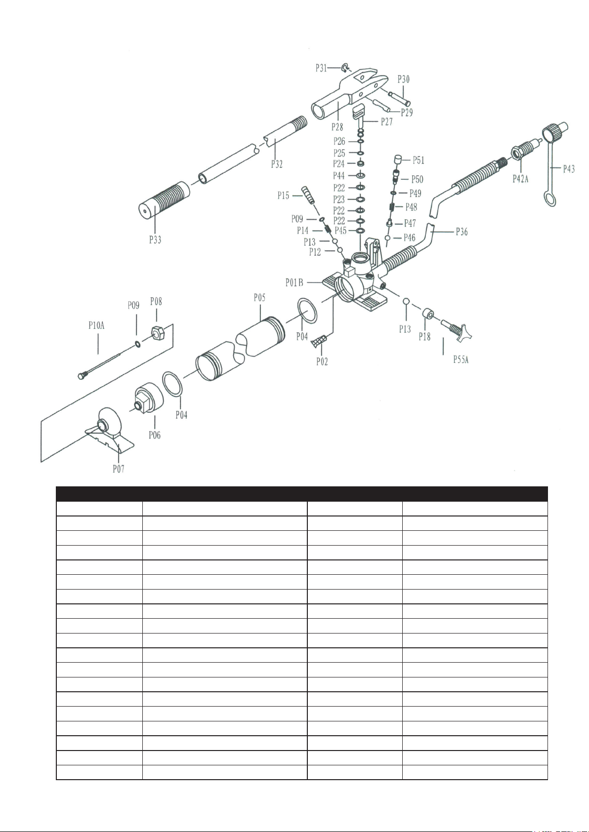
Hydraulic Body&Frame Pump 10 Ton Capacity
Part No. Description Part No. Description
11-P01B Pump Housing 11-P27 Plunger
11-P02 Filter 11-P28 Pump Pivot Brm Arm
11-P04 Seal 11-P29 Pivot Arm Pin
11-P05 Pump Reservoir 11-P30 Pivot Arm Pin
11-P06 Reservoir End Cap 11-P31 Cir Clip
11-P07 Pump Foot 11-P32 Pump Handle Assy
11-P08 Nut-Housing 11-P33 Grip
11-P09 O-Ring 11-P36 Hose
11-P10A Dip Stick(Oil Level CK) 11-P42A Coupling
11-P12 Ball Valve 11-P43 Dust Cap
11-P13 Ball Valve 11-P44 Back-up Ring
11-P14 Spring 11-P45 Back-up Ring
11-P15 Overload Stem 11-P46 Steel Ball
11-P18 Spacer 11-P47 Spring Plunger
11-P22 Seals (Complete Set) 11-P48 Spring
11-P23 Seal 11-P49 O-Ring
11-P24 Lower Spanner Nut 11-P50 Screw (Safety Valve)
11-P25 Seal 11-P51 Plastic Cap
11-P26 Upper Spanner Nut 11-P55A Release Valve Stem
Page 10

LIMITED ONE YEAR WARRANTY
Jackco Transnational Inc. warrants all Jackco equipment and tools to the original purchaser against any manufacturing defect in material or
workmanship for a period of one (1) year from the original date of purchase. If the defective equipment or tool is determined to be covered under
this warranty, it shall be repaired or replaced at manufacturer's discretion without charge, provided that the equipment or tool must be returned
with proof of purchase to the dealer and freight prepaid, if returned to the manufacturer. This warranty shall not apply to damage due to accident,
negligent use, and lack of maintenance, abuse or applications other than the specic function the equipment or tool is designed for.
No other warranties, expressed or implied, including those of merchantability or tness for particular purpose shall be applicable to Jackco
except as specifically stated herein. In no event shall Jackco be liable to any party for any special, direct, indirect, consequential, punitive
damage of any nature caused by the sale or use of the equipment or tool.
Note: This warranty gives the original purchaser specic legal rights which may very from state to state.
Jackco Transnational Inc. © 2009
South El Monte, CA
888-452-2526 www.jackco.com
 Loading...