

Page 1
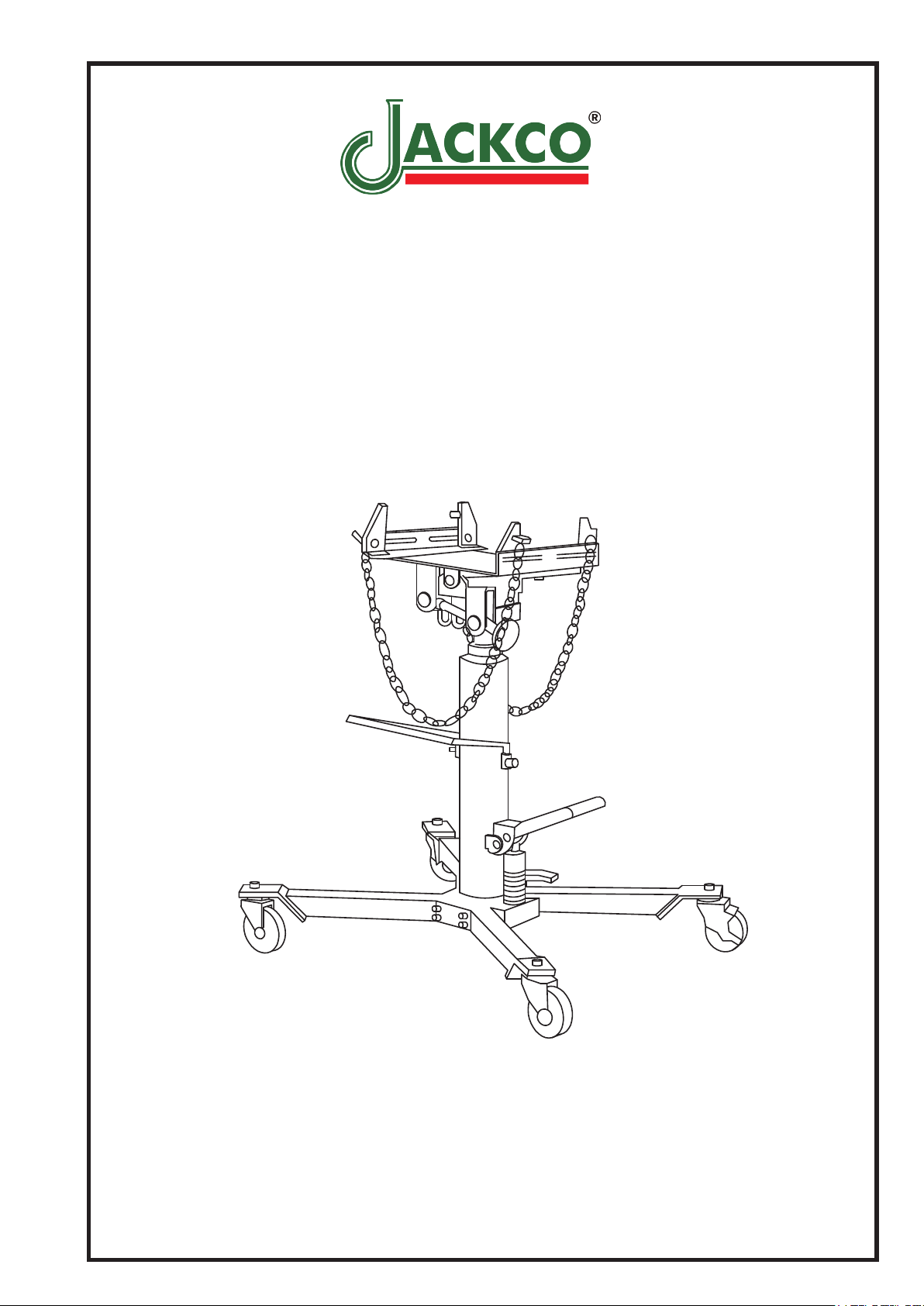
MODEL 766B
TRANSMISSION JACK
1/2 TON CAPACITY
USER'S MANUAL
Jackco Transnational Inc. © 2012
South El Monte, CA
888-452-2526 www.jackco.com
Page 2
FOR YOUR SAFETY
Read all instructions, warnings and cautions carefully. Follow all safety precautions to avoid personal injury
or property damage during system operation. Jackco cannot be responsible for damage or injury resulting
from unsafe product use, lack of maintenance or incorrect product and/or system operation. Contact Jackco
when in doubt as to the safety precautions and operations.
Failure to comply with the following cautions and warnings could cause equipment damage and personal
injury.
• Stay clear of loads supported by hydraulics.
A cylinder, when used as a load lifting device,
should never be used as a load holding device.
After the load had been raised or lowered,
it m u s t al w a y s be b locked m e chanicall y.
• Do not exceed equipment rating never attempt
to lift a load weighing more than the capacity
of the cylinder. Overloading causes equipment
failure a n d possible personal i n j u r y. The
cylinders are designed for a maximum pressure
of 10,000 psi. Do not connect a jack or cylinder
to a p ump w i t h a h i g h e r p r e s s u r e rating.
• The system o p e r a t i n g pressure m u s t not
exceed the pressure rating of t h e lowest
ra t e d c o m po ne n t in th e sys t e m . Ins t al l
pressur e gaug es in the system to m onitor
o p e r a t i n g pr e s s u r e . It is yo u r wi n d o w
t o w h a t i s h a p p e n i n g i n th e s y s t e m .
• BE S U R E SET U P IS STA B L E BE FO RE
LIFTING LOAD.
Cy l i n d e r s sh o u l d be pl a c e d on a fl a t
sur f ace that can supp ort the load . Where
applicab le, use a cylin der bas e for added
stability. Do not weld or otherwise modify the
cylinder to attach a base or other support.
• To avoid personal injury keep hands and feet away
from cylinder and work piece during operation.
• NEVER set the relief valve to a higher pressure
than the maximum rated pressure of the pump.
Higher settings may result in equipment damage
and/or personal injury. Do no remove relief valve.
• Keep hydraulic equipment away from flames and
heat. Excessive heat will soften packing and seals,
resulting in fluid leaks. Heat also weakens hose
materials and packings. For optimum performance
do not expose equipment to temperatures of 150°F
or higher. Protect hoses and cylinders from weld
spatter.
• Hydraulic equipment must only be serviced by a
qualified hydraulic technician. For repair service,
contact your equipment dealer / service center. To
protect your warranty, use only JACKCO hydraulic
oil.
• Avoid situations where loads are not directly
centered on the cylinder plunger. Off-center
loads produce considerable strain on cylinders
and plungers. In addition, the load may slip
or fall, causing potentially dangerous results.
• Immediately replace worn or damaged parts
genuine JACKCO parts. Standard grade parts
will break causing personal injury and property
damage. JACKCO parts are designed to fit
properly and withstand high loads.
Page 3

Specications
Assembly
Capacity Base Size(L x W) Min Height Max Height Net Weight
1/2 Ton 37" x 31" 38" 74 1/2" 154 Lbs
• Assembly the swivel casters on the jack legs using lock washers and nuts provided.
• Assemble the legs (with the casters) to the jack's base, and slightly secure with the Allen socket
bolts and lock washers provided.
• Position the jack (with legs) on a hard level surface. Tighten the Allen socket bolts while all four
casters are contacting the oor and the jack apppears vertical to the oor.
• Locate the draw bar and the two hex bolts in the carton, Insert the draw bar into its sockets on the
cylinder, and secure with the hex bolts provided.
• Saddle assembly: Loosen the bolt from outside the saddle adapter. Mount the saddle adapter
onto the top of the piston rod. Once mounted, tighten the bolt and secure entire saddle assembly.
• Use the tilt adjusting knob to adjust the saddel angle to a relatively horizontal positon.
• Attach the two corner support brackets onto the uniersal saddle, and fasten with the hex bolts and
nuts.
• Locate the xing bracket in the chain pack. Assemble the xing bracket on the corner support
bracket and secure with the hook and screw caps. Assemble chains and chain hardware to the
corner support bracket.
• The chains and chain hardware are provided to secure the transmission, transfer box, or
differential to the saddle assembly by the different shape of their housing. When using, both ends
of the chain should be anchored to the bracket.
Setup
• To prevent oil leak during shipment, a shipping plug is used to ensure the best sealing function.
Remove the shipping oil plug, and replace it with vented oil plug provided.
• The reservoir tube is shipped filled with hydraulic oil. Beofre using the jack for the first time,
press the release pedal to open the release valve, and operate the foot pump 8-10 full strokes to
distribute the oil.
Operation
• Follow the vehicle's recommended service procedure for removal of the component.
• Position the jack under the vehicle.
• Raise the jack by operating the foot pump until the saddle reaches the component.
• Adjust the suport brackets to t the component.
• Use the tilt crank to align the saddle with the component.
• Finish raising the jack to the component. Secure the chain assembly around the component.
Bleed Air from the Hydraulic System
Air can accumulate within a hydraulic system during shipment or after prolonged use. This entrapped
air causes the jack to respond slowly or feel "spongy". Follow the steps below to bleed the system :
To bleed the air in the oil system:
1. Pump the jack to the highest point where the first and the second stages are both at the
2. Get the help of another person to keep the release pedal depressed, and activate the foot pedal
3. Let go if the release pedal; the air in the oil system should be bled successfully.
To bleed the air in the second cylinder:
1. Locate the air bleeder screw at the top nut, which is on the top of the rst piston rod.
2. Pump the jack to its maximum height. Use an Allen socket wrench to loosen the air bleeder
3.Tighten the bleeder screw and double check. It may be necessary to repeat the above steps
maximum height.
about 15-20 times.
screw for no more than two full rotations. Push the saddle assembly downward to purge the air
in the cylinder out until nothing but oil drains out of the bleeding hole.
several times.
Page 4
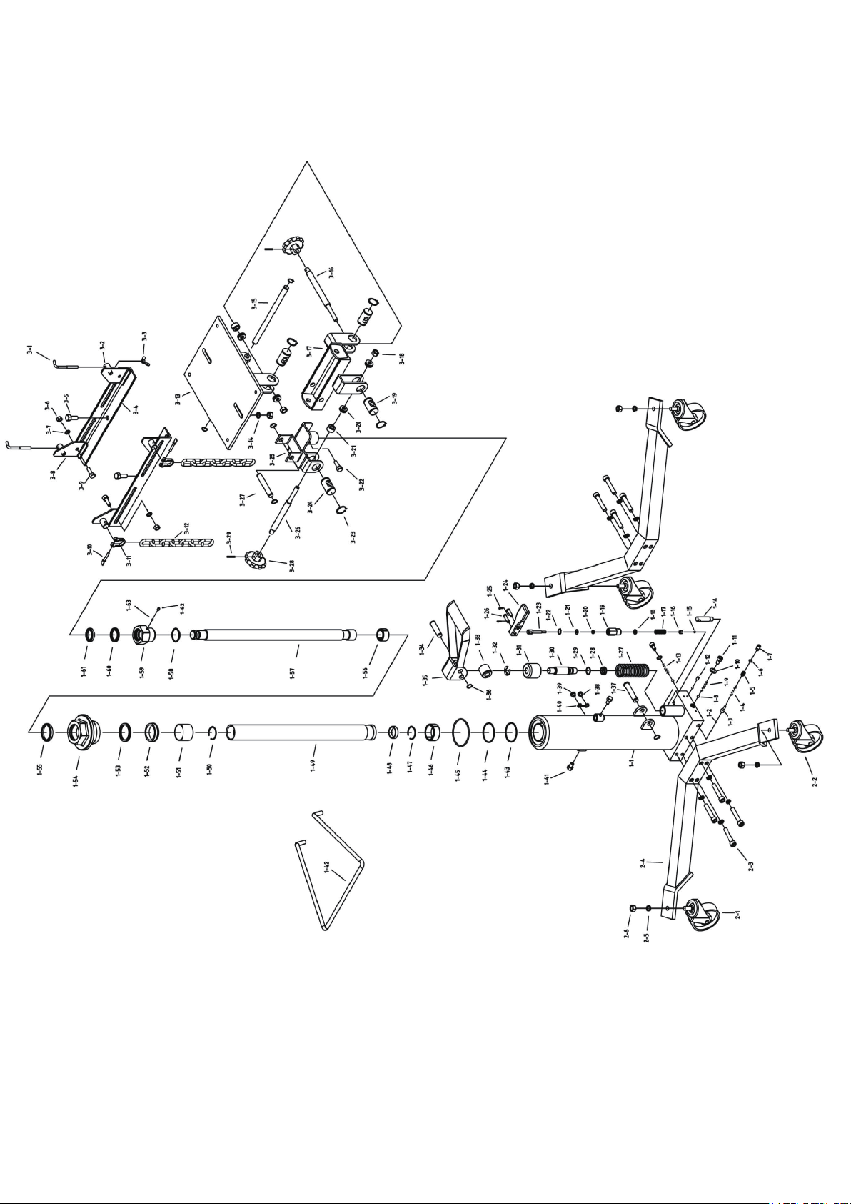
Model: 766B Parts List
Page 5
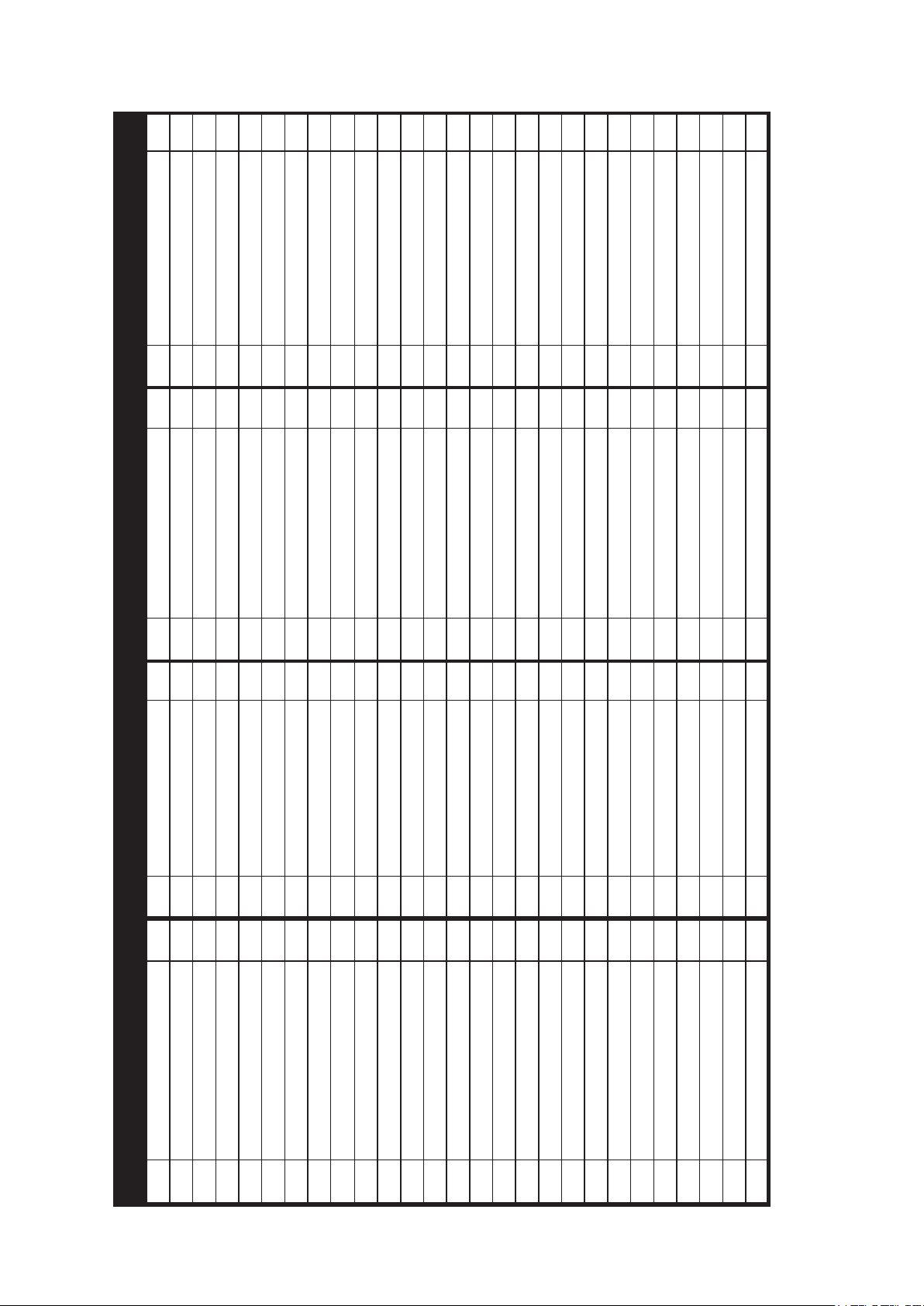
Description Q'ty
Part
Description Q'ty
No.
Universal Saddle 1
3-13
Dustproof 1
Flat Washer 2
3-14
Bushing 1
Shaft 1
3-15
Piston Rod 1
Screw 1
3-16
O-ring 1
Bracket 1
3-17
Screw Cap 1
Locknut 2
3-18
Y-seal 1
Shaft 2
3-19
Dustproof 1
Bearing 4
3-20
Steal Ball 1
Bushing 2
3-21
Air Bleed Screw 1
Bolt 1
3-22
Swivel Caster A 2
Snap Ring 8
3-23
Swivel Caster B 2
Shaft 2
3-24
Bolt 8
Bracket 1
3-25
Leg 2
Screw 1
3-26
Lock Washer 12
Shaft 1
3-27
Nut 6
Knob 2
3-28
Hook 2
Pin 2
3-29
Fixing Bracket A 2
--
--
--
--
--
--
--
--
--
--
Screw Cap 2
Corner Bracket 2
Bolt 2
Nut 4
Flat Washer 4
Fixing Bracket B 2
Bolt 4
Screw 2
Link 2
Safety Chain 2
Part
Description Q'ty
Part
No.
No.
1-55
Y-seal 1
1-28
1-56
O-ring 1
1-29
1-57
Pump Plunger 1
1-30
1-58
Spring Cover 1
1-31
1-59
Snap Ring 1
1-32
1-60
Bushing 1
1-33
1-61
Pin 1
1-34
1-62
Foot Pedal 1
1-35
1-63
Snap Ring 6
1-36
2-1
Pin 1
1-37
2-2
Screw 1
1-38
2-3
Screw 1
1-39
2-4
Sealing Gasket 1
1-40
2-5
Bolt 2
1-41
2-6
Draw Bar 1
1-42
3-1
Nylon Washer 1
1-43
3-2
O-ring 1
1-44
3-3
O-ring 1
1-45
3-4
Bushing 1
1-46
3-5
Snap Ring 1
1-47
3-6
Bushing 1
1-48
3-7
Inner Cylinder 1
1-49
3-8
Snap Ring 1
1-50
3-9
Bushing 1
1-51
3-10
Bushing 1
1-52
3-11
Y-seal 1
1-53
3-12
Screw Cap 1
1-54
Description Q'ty
Part
No.
Oil Cylinder Ass'y 1
1-1
Steel Ball 1
1-2
Ball Seat 1
1-3
Spring 1
1-4
Screw 1
1-5
O-ring 1
1-6
Bolt 1
1-7
Steel Ball 2
1-8
Spring 1
1-9
Copper Washer 2
1-10
Bolt 2
Screw 4
Spring 1
Rod 1
Steel Ball 5
Ball Seat 1
Spring 1
Copper Washer 1
Oil Release Valve 1
O-ring 1
Washer 1
Snap Ring 1
Oil Release Rod 1
Oil Release Pedal 1
Pin 2
Pin 2
Spring 1
1-11
1-12
1-13
1-14
1-15
1-16
1-17
1-18
1-19
1-20
1-21
1-22
1-23
1-24
1-25
1-26
1-27
Page 6
Maintenance
Regularly lubricate all moving parts of the jack. Pay special attention to the lift screw and related
linkages.
• A meidum weight lubricating grease sould be used on all external moving parts, such as bearing
surface, pivot points tilt screws, etc.
• Regularly check the oil level. With the saddle fully lowered, remove the oil ller screw, and check
the oil level. Oil should be at the bottom of the ller screw holes. Fill if nessary.
• Use only hydraulic jack oil. Do not use hydraulic brake uid.
• If the jack fails to operate, check the oil level and/or bleed until before seeking service.
• Do not use this jack as a wash rack when washing or steam cleaning transmissions.
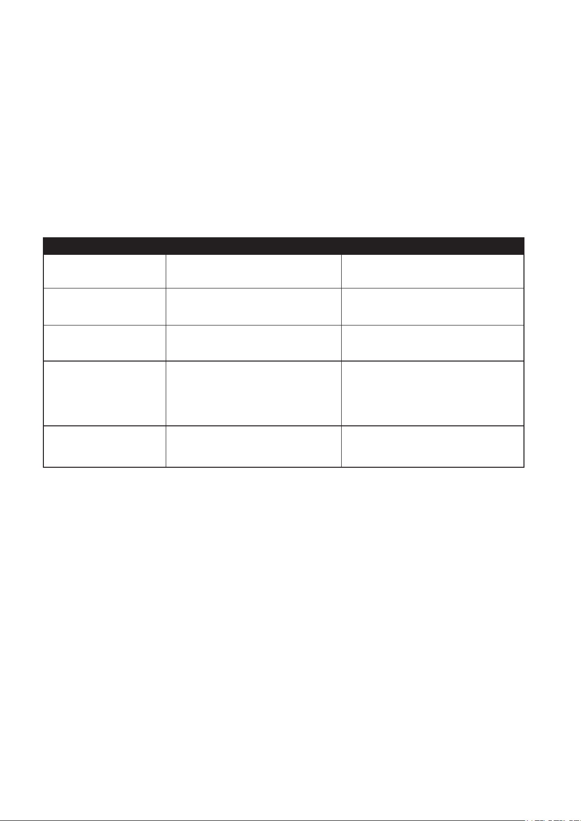
Trouble Shooting
Problem Cause Solution
Jack will not lift load • Overload condition
• Air supply inadequate
Jack bleeds off after lift Overload condition Remedy overload condition
• Remedy overload condition
• Ensure adequate air supply
Jack will not lower after
unloading
• Resevoir overlled
• Linkages Dinding
Poor lift performance • Fluid level low
• Air trapped in system
Will not lift to full
Fluid level low Ensure proper uid level
extension
• Drain uid to proper level
• Clean and lubricate moving parts
• Ensure proper uid level
• With ram fully retracted, remove
oil ller screw / vent screw to
let pressurized air escape, then
reinstall oil ller screw/ vent screw
LIMITED ONE YEAR WARRANTY
Jackco Transnational Inc. warrants all Jackco equipment and tools to the original purchaser against any manufacturing defect in material or
workmanship for a period of one (1) year from the original date of purchase. If the defective equipment or tool is determined to be covered under
this warranty, it shall be repaired or replaced at manufacturer's discretion without charge, provided that the equipment or tool must be returned
with proof of purchase to the dealer and freight prepaid, if returned to the manufacturer. This warranty shall not apply to damage due to accident,
negligent use, and lack of maintenance, abuse or applications other than the specic function the equipment or tool is designed for.
No other warranties, expressed or implied, including those of merchantability or tness for particular purpose shall be applicable to Jackco
except as specifically stated herein. In no event shall Jackco be liable to any party for any special, direct, indirect, consequential, punitive
damage of any nature caused by the sale or use of the equipment or tool.
Note: This warranty gives the original purchaser specic legal rights which may very from state to state.
Jackco Transnational Inc. © 2012
South El Monte, CA
888-452-2526 www.jackco.com
 Loading...