

Page 1
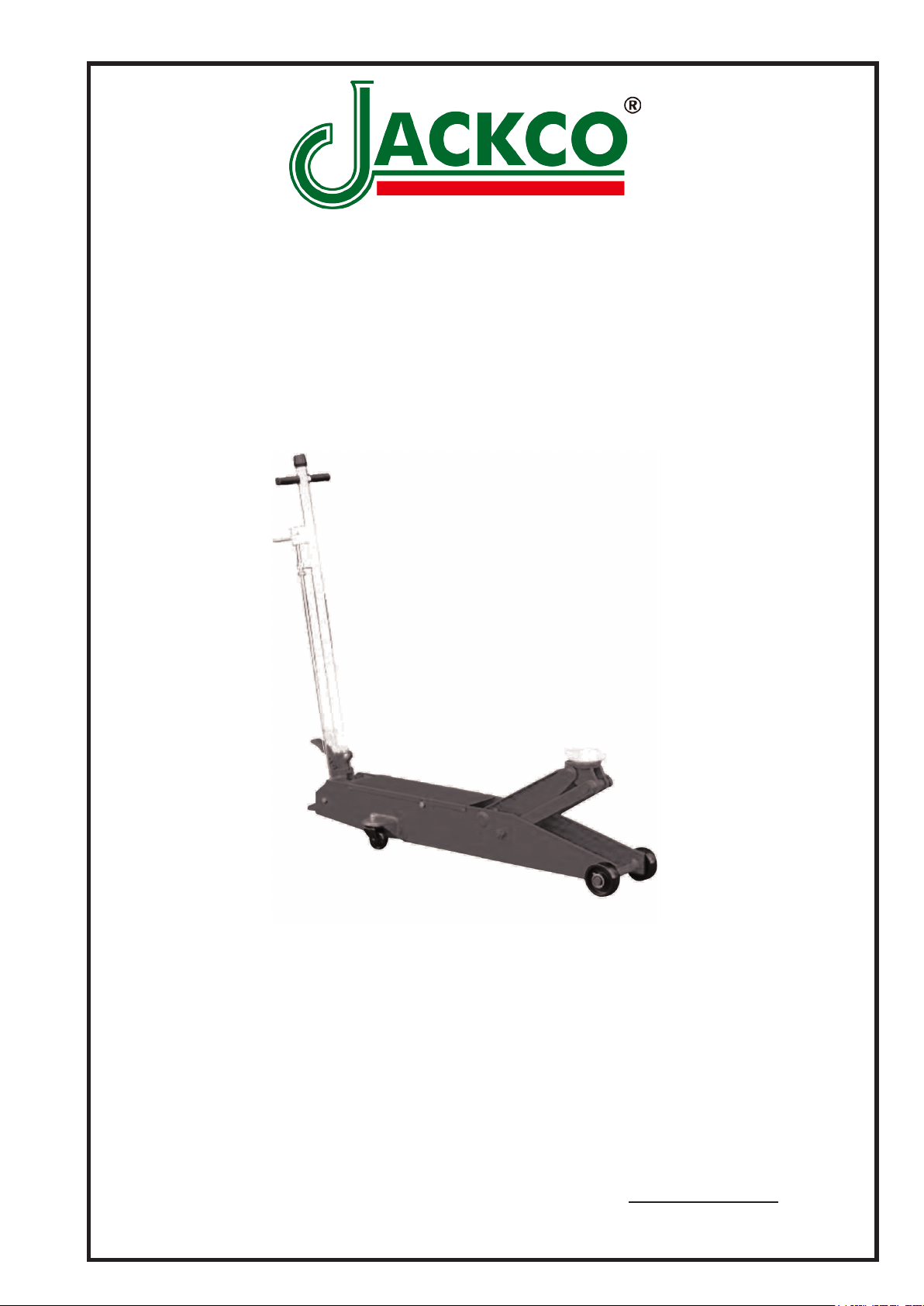
MODEL 66500
5 TON HYDRAULIC
FLOOR JACK
USER'S MANUAL
*This hydraulic jack conforms to all "ANSI / ASME" safety standards.
Jackco Transnational Inc. © 2010
South El Monte, CA
888-452-2526
To see more jackco products please visit our website at www.jackco.com
Page 2

FOR YOUR SAFETY
• Read these safety instructions carefully and keep this manual in an easy to nd place as
you may need to use it again.
• Non-compliance with these rules may result in injury or damage to the jack or the vehicle.
• Do not modify the jack in any way.
• Never exceed the rated capacity of the jack.
• This jack is a lifting device only and should never be used to move the vehicle.
• The jack should be supported on a solid and level ground. Never use the jack in a surface
where it may sink into the ground.
• Ensure that there are no persons inside the vehicle to be lifted. Switch off the engine and
apply the brake.
• Position the jack under the manufacturer’s recommended lifting point for the vehicle. Offcentered loads can slip and accidents may result.
• During raising and lowering of the load, precautions should be taken to avoid movement
of the vehicle. Trafc may cause the raised vehicle to rock during roadside use of the
jack.
• Never work under a raised vehicle without supporting it with mechanical/jack stands.
• Never position any part of your body near the movable parts of the jack.
• Ensure that there are no persons or obstructions underneath the vehicle prior to lowering.
• Do not adjust the overload bypass valve under any circumstance.
Use wheel chocks appropriately
2
.
Page 3
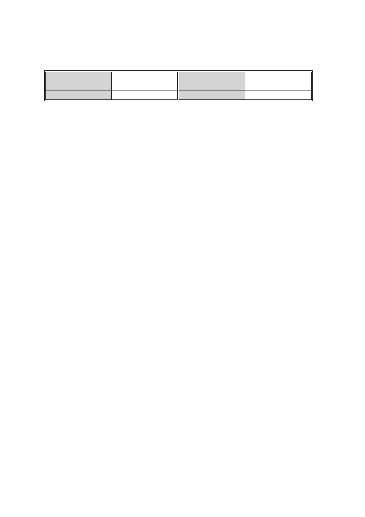
SPECIFICATION
Capacity:
Max Height :
Min Height :
5 Ton
22 inch
5.9 inch
Lift Range :
Gross Weight
Net Weight :
16.1 inch
222 lbs
191 lbs
OPERATING INSTRUCTION
Important: Sometimes during shipment and handling, air gets into the hydraulic
system, causing poor lifting performance. Before initial operation, purge any air from
the system by fully opening release (Turn handle knob (#3-8) counter-clockwise).
Then, while holding the saddle down, pump pedal (#3-2) rapidly several times.
To Lift a Vehicle:
1. Turn handle knob (#3-8) clockwise until resistance is felt to close release valve.
Do not over-tighten.
2. Place jack directly under object to be lifted. Make sure saddle takes up weight
rmly and centrally. Check positioning under slight load to conrm jack or load will
not slip.
3. Raise jack by pumping handle until desired height is reached. After lifting, secure
load by appropriate means. Do not use jack as the only means of support.
To Lower a vehicle:
1. Slowly turn handle knob (#3-8) counter-clockwise. Speed of descent is controlled
by amount release valve is turned.
3
Page 4

MAINTENANCE
Important:
Both the maintenance and repair of the jack may only be performed by
qualied persons, who have sufcient knowledge of the hydraulic system used in these
jacks
Regularly lubricate the moving parts in the wheels, arms, handle
and pump roller pin.
• Checking hydraulic oil level
1. Open release valve (Turn handle knob (#3-8) counter -clockwise and push ram to
its lowest position.
2. Remove ller plug.
3. Fill the clean hydraulic jack oil .Do not use hydraulic brake uid .
4. Reinstall ller plug .
• Only original replacement parts should be used.
Extremely Important:
never use brake uid.
• When the jack is not in use, make sure the lifting arm is fully retracted to avoid
corrosion.
• Keep the jack in a clean, dry place and out of children’s reach.
• Replace the hydraulic fluid in the reservoir at least once a year. To check the
hydraulic uid level, lower the lifting arm completely.
• The hydraulic uid level should be just below the ller plug. Replenish if necessary,
and reinstall the rubber filler plug. Excessive hydraulic oil may render the jack
inoperative.
• Inspect the jack before each use. Take corrective action or remove the jack from
service if any of the following problems are found:
a. Cracked or damaged frame b. Leaking hydraulic uid
c. Scored, damaged piston rod d. Loose hardware
e. Modied equipment
• Keep warning labels and instructional decals clean and readable. You may use a
mild soap solution to wash external surfaces of the jack.
4
Page 5
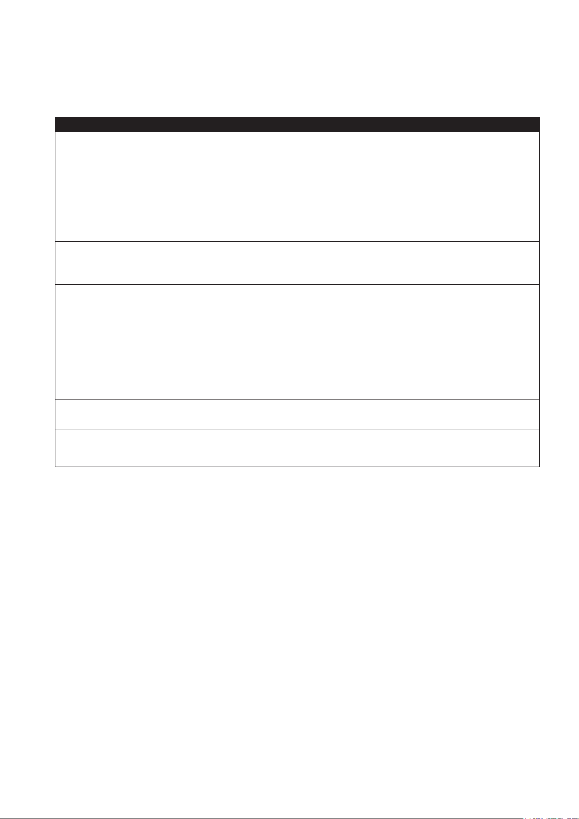
TROUBLESHOOTING
Caution: To prevent personal injury, all inspection, maintenance, and repair
procedures must be performed when the jack is free of load.
Trouble Cause Solution
1) No hydraulic oil 1) Fill hydraulic oil
2) Release valve opened 2) Try again to rotate the
handle to insure position
Does not lift at all
Lifting only half way
Load will not hold
Does not lower
Poor lifting
3) mal-functioned delivery
and / or by-pass valve
3) Check for dust of foreign
debris and clean
4) Packings defective 4) Replace packing
5) Lack of hydraulic oil (in
5) Fill hydraulic oil
most case)
6) Improper contact of
suction valve, delivery and/
or by-pass
6) Clean valves and adjust
valves contact
a) Lifting is improper contact of
suction valve
b) Lowering is improper
contact of delivery valve
7) Worn out piston packing 7) Replace packing
8) Release valve obstructed
8) Clean release valve
by foreign debris
9) Defective pump packings 9 ) C l e a n va l v e s re p l a c e
packings, replace hydraulic oil
5
Page 6
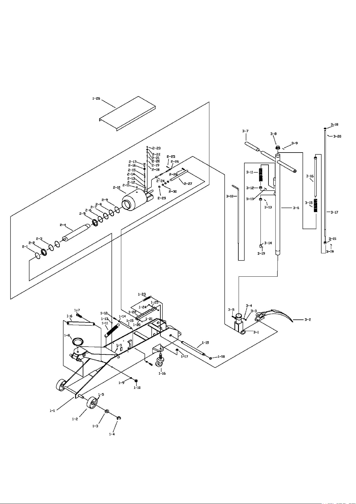
PARTS LIST
Page 7
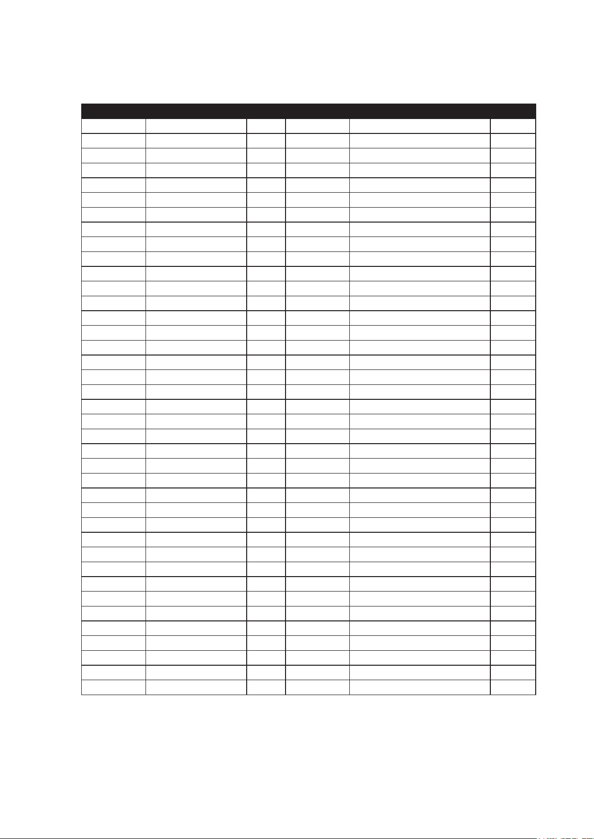
Part No. Description Q’ty Part No. Description Q’ty
1-1 Frame 1 2-14 Steel ball φ9 1
1-2 Front wheel 2 2-15 Spring 1
1-3 Washer 2 2-16 Copper washer 1
1-4 Snap ring 2 2-17 Bolt M12x20 1
1-5 Grease tting 3 2-18 Steel ball 1
1-6 Rod link 2 2-19 Valve seat 1
1-7 Bolt 2 2-20 Spring 1
1-8 Saddle 1 2-21 Screw 1
1-9 Lock washer 2 2-22 O-ring 1
1-10 Nut 2 2-23 Safety valve screw 1
1-11 Spring 1 2-24 Seals 1
1-12 Bolt M10x25 2 2-25 Pin 1
1-13 Bolt M10x16 1 2-26 Release valve rod 1
1-14 Snap ring 2 2-27 Cylinder pump plunger 1
1-15 Shaft 1 2-28 Pin 1
1-16 Rear wheel 2 2-29 O-ring 1
1-17 Nut 2 2-30 Nylon gasket 2
1-18 Snap ring 2 3-1 Handle socket 1
1-19 Shaft 1 3-2 Pedal 1
1-20 Washer 1 3-3 Nut M10 1
1-21 Pin 1 3-4 Washer 1
1-22 Connection bar 1 3-5 Bolt M10x35 1
1-23 Spring 1 3-6 Handle 1
1-24 Snap ring 2 3-7 Handle sleeve 2
1-25 Shaft 1 3-8 Knob 1
1-26 Cover board 1 3-9 Pin 1
2-1 Snap ring 2 3-10 Control rod 1
2-2 Washer 1 3-11 Spring 1
2-3 O-ring 1 3-12 Washer 2
2-4 Piston rod 1 3-13 Screw 2
2-5 Piston ring 1 3-14 Rod joint 1
2-6 Sealing washer 1 3-15 Spring 1
2-7 O-ring 1 3-16 Universal joint ass’y 1
2-8 O-ring retainer 1 3-17 Convey rod 1
2-9 Snap ring 1 3-18 Washer 1
2-10 Oil cylinder ass’y 1 3-19 Pin 2
2-11 Oil ller plug 1 3-20 Pin 1
2-12 pin 2 3-21 washer 1
2-13 Steel ball φ6 1
Page 8

LIMITED ONE YEAR WARRANTY
Jackco Transnational Inc. warrants all Jackco equipment and tools to the original purchaser against any manufacturing defect in material or
workmanship for a period of one (1) year from the original date of purchase. If the defective equipment or tool is determined to be covered under
this warranty, it shall be repaired or replaced at manufacturer's discretion without charge, provided that the equipment or tool must be returned
with proof of purchase to the dealer and freight prepaid, if returned to the manufacturer. This warranty shall not apply to damage due to accident,
negligent use, and lack of maintenance, abuse or applications other than the specic function the equipment or tool is designed for.
No other warranties, expressed or implied, including those of merchantability or tness for particular purpose shall be applicable to Jackco
except as specifically stated herein. In no event shall Jackco be liable to any party for any special, direct, indirect, consequential, punitive
damage of any nature caused by the sale or use of the equipment or tool.
Note: This warranty gives the original purchaser specic legal rights which may very from state to state.
Jackco Transnational Inc. © 2010
South El Monte, CA
888-452-2526 www.jackco.com
 Loading...