

Page 1
~PORTANTSAFETYINSTRUCTIONS
Putting sewing systems into operation
which these sewing machines will be built into, have conformed with
Technical service for those sewing systems
!.Observe
machine.
2.Read a
In addition, keep this instruction
3.Use the machine after it has been ascertained
country.
4.AII safety devices mu
without the specified safety devices is
S.This machine sha
6.For your personal protection, We recomme
7
.For
receptacle.
7-1
7-2
7-3 For
7-4 When leaving the working place
7-5 When using clutch motors
8.1f you should allow oil, grease, etc. used with the machine and devices to come in contact with your
skin
doctor.
9.
Tampering with the live
IO.Repair, remodeling
specially skilled personnel. Only
ll.General
l2.Repair
or
Whenever you find a failure
l3.Before making
air
be
expelled. Exceptions to this
technicians
14.Periodically clean the machine
the bas
ll
the
the following,
For threading needle(s), looper,
For
folder, cloth guide etc.
repair
or
swallow any
and
under
cylinder,
cut
off. Existing residual
ic
safety measures, including,
instructions, including,
st
be in position when the machine is ready for work
ll
be operated by
turn
off the
rep lacing part(s)
work.
maint
enance
maintenance works
the
audit
and
repair
the
air
or
specially skilled personnel.
of
of
such liquid by mistake, immediately wash the contacted areas
parts
and
adjustment
and
inspection works have to
guidance
and
maintenance works on
compressor bas to be det.ached from
air
needle, presser foot,
and
of
are
is
prohibited until it bas been ascertained
is
also proh.ibited.
but
but
not limited to this instruction Manual before you use the machine.
Manual
appropriate
power
without
devices, regardless
spare
of
of
any
pressure
only adjustments
throughout
so
that you may read
that
not
allowed.
ly-trained operators.
nd
that
you
switch
spreader
or
when the working place
app
works must only be done
parts
electrical components
specially skilled personnel.
of
electrical components, immediately stop
after disconnecting
or
etc.
and
lying brake,
designated by
the period
that
the sewing systems
the
safety regulations in your county.
not limited to the following ones, whenever you u
it
at
anytime when necessary.
it conforms with safety rules/standards valid
or
in operation. The operation
wear
safety glasses.
disconnect the power plug
replacing bobbin.
throat
the
and
plate, looper, spreader, feed dog, needle guard,
is
unattended.
it
has to be waited until the
of
whether the machine
by
appropriately trained technicians
JACK Can
be
done by appropriately trained personnel.
sha
ll
be conducted by qualified electric technicians
machine equipped with pneumatic parts such as an
the
machine
the
performance checks
of
use.
be
used for repairs.
and
air
compressor from
of
the
machine from the
motor
stopped totally.
and
consult a medical
is
powered, is prohibited.
the
machine.
the compressed
done
by
air
the
machine bas to be
appropriately trained
supply bas to
se
in
eyes
in
the
your
or
or
IS.
Grounding
be operated in
l6.An
appropriate
connected to a 2rounded receptacle.
l7.The machine is only allowed to be us ed for
l8.Remodel
safety measures.
machine.
l9.Warning hints are marked with
the
machine
an
environment
power plug has to
or
modify the machine in accordance with
JACK
is
always necessary for the normal operation
that
is
free from strong noise sources such as high-frequency welder.
be
attached to
the
assumes
Danger
Items requiring special attention
of
no
responsibility for
the
two shown symbols.
injury
to
operator
of
the
the
machine by electric technicians. Power plug has to be
purpose intended.
the
safety rules/standards while taking all the effective
damage
or
service
Other
used
caused by remodeling
staff
v
machine. The machine has to
are
not
allowed.
or
modification of the
Page 2
&
~~
&
1.
~7~~~~
M~$~.
~~~~fl~~~
.. #.
1.
~T~~A~
2.
~T~~$Afia~A~•~·
::
p~re~
-~
~£~. ~~~~~~~m~~a~~~~~~~*~~~mm.
~:tt~~
J~mm...t.
~~*~·fl*~~-~~&Mm~~·~~
•mm~~~.
~~~re~m,~~,~ma~~~.~
~-
3.
~T~~A~-~~~~.n*~-~~&•mm~~~.~~~re~mtt~m~~~~.
4.
~r~~A~-~~~~
s.
•mm~*~·
6.
~r~~A~-~~~~.
1.
~Y~~~~~~~~~~-~.tt••mm~~£~*-ftl:
s.
Mmm~~~~~~~F~·~Y~~~~~~~~-~.~tt·~~~~**~~
9.
~T~~M~•~·
10.
~T~~il!~~~t+~~~#.
~-~~~~.~Y~~~~~~~.~~~~~M~~re~3~~~.
.
•mm~~~~~~re¥mtt~m~~*~~.
tt••mm~~§~*~~~.
~~~-~~~~~.~~~~~•mm.
t£~-~~~111.
~;tWIT~~.
~~-~~~~•·
,
~•~~~**~~.
~r*~~•
~~~•~fm•~~••·~~~oo~~~-m~&~~n~••~~
.
••~~~,~~~~~&~.
.
~~U
f & ~~
~'{ttl:fj;~iG
1*1
Vi
li:-'Fm
vi
~
.t1:
til
f@.
,
r.u~
fg:
~~iCY£~~~
~
Er~
:rc
Page 3
l.To
~
avo
id
electrical shock hazards, ne
components mo
FOR
unt
ed inside the electrical box.
SAFE OPERATION
ith
er
open
the
cover
of
the electrical box nor touch
the
&
l.To avoid personal injury, never
devices removed.
2.To prevent possible personal injuries caused by being caught in
head
an
d clothes away from the handwheel while the machine is in ope
place nothing around it.
3.To avoid personal injury, never
power switch or operate the machine.
4.To avo
S.The hook rotates
6.To avoid possible persona l injuries, be careful n
7.To
8.The motor does not produce noise while the machine
9.To avoid elec
JO.To
id
personal injury, neve r put
machi
ne
is
in
opera
tion.
at
h high speed while the machi
to hands, be s
addit
ion
tilting /rai sing the machine head.
avoid possible accidents because of
machine when tilting the m
the machine, etc.
to
abrupt start
the power supply removed.
prevent possible accidents because
turn
OFF the power switch in
, be
ure
to keep your hands away from
sure
to
turn
OFF the power to
of the machine, be sure to
tri
cal shock h
operate
put
your
your
abrupt
ac
hine b
ead
azards, never
prior
to the connection/disconnection
the
machine with
hand und er the needle when you
fin
gers
into
ne
is
the
vicinity
the mac
or performing
turn
operate
of
electric shock
hine when replacing
ot
to allow yo
start
of
OFF the power to
the sewing machine with the ground wire for
any
the
in
operation. To prevent possible injury
of
the machine,
rep
laceme
is
at
rest.
or
damaged el
of
the
finger
the
mac hine, keep you
thread
ur
take-up cover while the
the
book
the
fing
ers
turn
OFF
nt
of
To
avo
id possible accidents due
the
machi ne.
ectr
of
the power plu
guard
or
safety
fin
gers,
rat
ion. In addition,
turn
"ON" the
during operation .. In
bobbin.
in the machine when
the
power to the
parts,
adjustment of
ical componeot(s),
g.
vii
Page 4
3~1JJ1Ifll
·
·····
····················
············
·····
·······
··················································································1
~~fit~
t.
~m
2.
~~m
3.
•
4.
~~A<J~~
1Jll~
5.
6.
~;fl:ilb:fitA<J~ll
7.
~tt~:fit
s. m
9.
;f:t
10.
fil~*l:t.A<J~~
11.
.ffi~.ffijJ
12.
J:~~~1J~
13.
Jif~!l:lr~1Jt!··
14.
~
;t1
t
Htr
A<J
tt
it
$ tjji .......•.......•.•..
...
.......................................
A<J
i9.J
~
~~·····
7t
jtfj
·
···········
IJt.
t¥.1 ~ •···········
····
·······································································
(8990
SS,
899l
SS)
(
8990SS,
(~~)
tt
~J
~~:n~
JL\
99
~~1i1;i.;:
a<Jiq~·······
a<J~)I1J~
····
···········
···
····
····
·······················
··
·························
····
··
·············
.........................................
···
·········
·······
31i:1J
···············
·
············
~t'f!!~!!~!!I'!!
·····························································································
···
·········
.•.
••.••.•...•••...•.•.•..•..........
............
··········
··
............................
....
...
·
·· ······
····
· ·
....
.................
··
·····································
·············
...................
..
8991SS) ......................................
(
8990SS,
···········
············
·
··········
·
·······
···········
· ··
···
··············································································
I'
I'!P
·!!·
!!!!!!-
!!
!!-
!!
!!-
!!!!!!1'1'1'!!
8991SS) .....................
···························
· ·
····
···
····
·········
··········
············
.....
!! !!-1'!!
···············
·······
············
......................
····
·1'··
·· ·· ······
···
· ·······
··•···•····••••
.....................................................
·················
· · ·
·········
· ·
·········
···
····················
··
······················
........
...
···············
··•·••···················•········· 2
.
.................................
·
·······
·········
·····
·
···
····· ·····
3
4
5
·········
····················
...........................................
......
...............................
···
····
·············
·······································
·······
·········
···
·
··
······ ··· ······
....
..........
....
.....
...................
·~~""
". '"'···
···--
····
··
··
······ s
·
·····
·· ·· ·
·······
··
····
········10
·· ··
··
··l
11
··
·····
12
-
·····
-
·····-··-·-·
13
5
6
7
s
9
O
15
.
~~-··· · ·
16.
m~:ffm~
17
.
.:tn.~.Wll:~:Wt¥.1~·
18
.
-~
.ffiJJ~tr~
19.
Wf~t¥.1~-
20.
-~·*·····················
21.
•
ti
-=¥-
22.
m~:ff
23
.
.:tn.
tt.!:ii~
24.
ra1
):E.
7J
25
.
~$~
26.
£5$89fi'i.J~
27
..
*!lt¥.111J11.-~
•
2 8.
~#f¥.*-
t.ffi
······
·······
·· ·
····
·
···············
:fit89~~·······
···
···············
··
·········
i9.J
{!lj
til
··········
.......................
~t¥.1
~~···
··························
t¥.J
ifli/Jt.~ffil~/Jt.
····
·
··
···
········ ················
.:tn.~····
1Jifl~71-·······
....................
··
·············
...
........................
···
·
·············
····················
··
··
····
··
····
··························
.........
...................................
·····
·
······
····
··········
..
..............................................................
······
· ··
·············
·································································
........
.....
·····
········
...............................
····
···
·
··········
........
..................................................
·······················································
··
···············
..
······························································ ...
········
·····
····
···
-····-··
··································
.. ···············
······
···
·····
.............................
····
·····
························
···
·
············
···
·
······
................
··· · ·
···········
····
· · ·
··
··
···
····················································
···········
..................
.. ····
·····················
···
······
··············
..................................................................
·
··
·····
······
···················
......................
·
····
····················
.......
··
·· ..
...........................................
...
......................
......
....
.......
·····
······························
...............................................
......
.......................
····
·············
.......................................
······
.. ·················
·····
··
···················
···
······
·······
·····
·
·······
····
···············
··
·········14
15
··
········
·······
15
.....
..........
..
17
18
18
19
21
..
22
····
········
······
23
24
···············
······
··
· ··
25
·········
26
· ····
···
·
27
....
28
viii
Page 5
CONTENTS
SCHEMATIC
BEFORE OPERATI
1.
SPECIFICATIO
2.
INSTALLATION··················································································································· 4
3.
ADJUSTING
4.
INSTALLING
LUBRICATIO N(8990SS, 8991SS)·····················································································5
5.
6. ADJUSTING
7. ADJ
8.
9. SETTING
10. ADJUSTING
11
. PRESSER
12. THREADING
13 . WINDING THE BOBBIN TRREAD··· ................................................................................. J2
UST
(8990SS, 8991SS)··················································································································7
ATTACUING
DIA
GRAM OF
ON·········································································
NS
················································································································ 3
THE
HEIGHT
THE
THREAD STAND··············································································· 5
THE
AMOUNT
ING THE AMOUNT
THE
NEEDLE·································································································8
THE
BOBBIN INTO
TUE
STITCH
FOOT
PRESSURE .............................................................................................. 10
THE
MACHINE HEAD ...............................................................................
THE
LENGTH
MACHINE TABLE······························ ....................
····
··································· 2
OF
THE
OF
OIL
OF
OIL(OIL
THE
KNEE
IN
BOBBIN CASE .............................................
...............................................................................
LIFTE
THE
SPLASHES)IN THE HOOK
R·····················································5
HOOK
(8990SS, 8991SS)··················6
....
....
....... 9
JO
I
Jl
14. THREAD
15. TOREAD TAKE-tJP SPRING ............................................................................
16.
ADJUSTING
17.
ADJl
18. PEDAL
1
9.
ADJUSTMENT
20. PEDAL
21
. ONE-TOUCH TYPE REVERSE
22. WIPER ··································································································································21
23. NEEDLE-TO-HOOK
24. COUNTER KNIFE ...............................................................................................................
25. HEIGHT AND TILT
26.
ADJl
27. THREAD TENSION RELEASE RELEASING MECHANISM ....................................... 26
MICRO-LIFTING MECHANISM
28.
TENSION ..............................................................................................................
THE
THREAD TAKE-UP
TSTING THE NEEDLE S
PRESSURE
OPERA'
iSTfNG
THE
AND
PEDALSTROKE
OF
THE
PEDAL ........................................................................................ J8
I.l0N···················
RELATIONSHIP
OF
THE
FEED
TIMING
TOP POS
··················································
FEED STIT
FEED DOG ........................................................................
STROK£
mON
............................................................
................................................................. 15
.....................................................................
·······································18
CHING MECRANISM ............................ 19
........................................................................
......................................................................................
OF
THE
PRESSER FOOT ......................................
......
............ 14
..
13
15
17
22
23
24
25
27
PARTS
BOOK
......................................................................................................................... 28
ix
Page 6
S
CHE
~*&1.mil!J
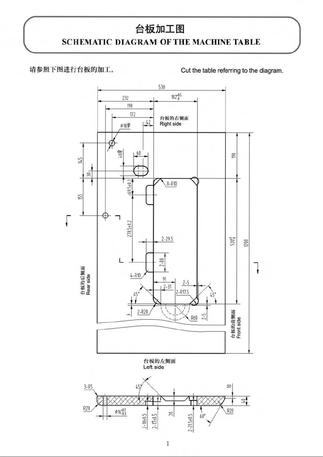
MATIC DIAGRAI\tl OF THE MACHINE TABLE
Cut the table referring to the diagram.
SJO
m
198
172
~
~
1Btis
Er~(J{J
;fi"
Right side
t'li"Ai
v
II
~
C>
,....
...,..
"'"!
C>
.,
OJ")
<>-
...,
~
J
" I I
..J
I
,....-
'--
- r
v
~
'\
~
r
}§
•
ill!
~
;g<Jl
$ lii
40
~
..,
L
......
<=>
.......
~
"'
4-R10
'""
4
5"
I
2-R20
Z-29.5
""'
<>;>
-
.....
91
2-31
'\
~
I I
\
'-.-,_....
'
....
-!_........
~~ftt:JtcMffii
Left side
Z-5
2
-R17.5
1-x
~-/i
I
R60
L"
v
":"
"'
45
C>
1r
C>
......
!;:::!
l
.
\
!§
.Q)
~:2
~!!
~a
40U:
Page 7
•
ii1iPr~f'JJ~Uft
·
ss••~·
•
:liW~ffl~W.tflZ~,
•
frt~j:gj!Jt~~;g:(!(J~~.
•
i1Hiff1iA
•
iWrdtlV..
•
ttffia~:f~~.
•
iiHdu
•
-wf:f~re~f'JJ.trl!IUlitrff!J,
•
*~f'JJ.trl~~fl".trl~~{fiJ.5:fi.t~f'JJ.tfl~l;fji¥J3f~.
~~±E
ttffi>ri~
It~~~~~
V..
~
~Bl
~~wm~
A
CAUTIO
~
~ J:~~~¥J~~Kfi.
(
trt5)
0
~mz~•-~ttM~~~--
i~HE..trl~trtFF-~o
:U=~Mo
~ ~
lE
~ o
lE
rdfl:it~
•~~:f~~m
~~H~
1¥1
ME~
.•
JErdfl~~~~mm~,rg~tJ3ftt~3f~o
N:
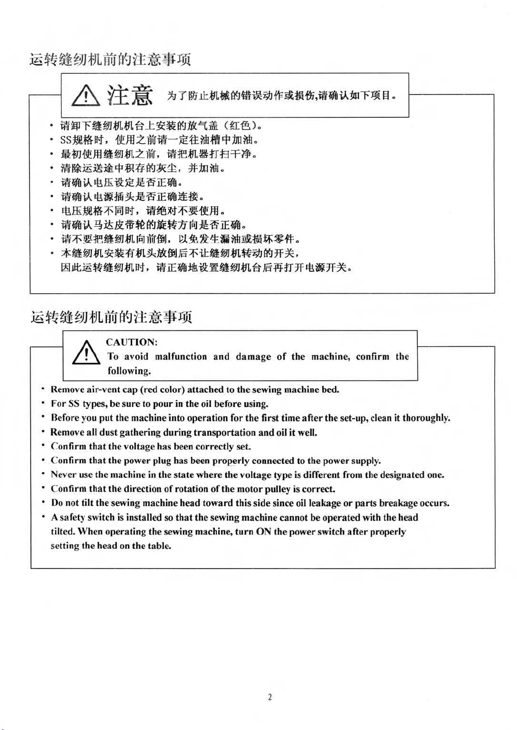
To avoid malfunction
following.
0
0
:1J
JiU
:J!~
lE
rdfl
o
PJ.~~1:.~~M~tvl~~#o
and
damage
of
the
machine, confirm the
• Remove air-vent
• For SS types, be s
• Before you
• Remove all dust gathering
• Confirm
• Confirm
• Never use
• Confirm
•
Oo
• A safety switch is in
tilted. When operating the sewing machine,
setting
that
that
that
not tilt the sewing machine head toward this side since
the
cap
(red color) attached to
ure
to
pour
in the oil before using.
put
the machine into operation f
during
the voltage has been correctly set.
the
pow
er
plug bas been properly connected to the pow
the
machine
the direction
head on the table.
in
the state where
of
sta
lled so
transportation
rotation
that
of
the
sewing machine cannot be operated with the head
the
or
the
voltage type is different from tbe designated one.
the
motor pulley is correct.
turn
sewing machine bed.
the
first time aft
and
oil it well.
ON
the power switch
oil
leakage
er
the set-up, clean it thoroughly.
er
suppl
y.
or
parts
breakage occurs.
after
properly
2
Page 8

}Hiif
~~;J,illi}jt
41.k
'tf·
~
L\:
JJt
1\!!J.IHJV
ol
II~I
I~I,
·.~il.!r
(
l~t;JJ.WJI·)
ttifHr~
-ftJf.ltdE~
Ifl:ftM!.t
m~.R-t
1\l!JII-I'Ililh
1. SPECIFICATIONS
8990SS
-Alt:tfif4,
~if,ljfij7f
13
7;tJ;btl
JACK
New
I
tWM,
~
Defrix
8991SS 8990DS
cp
J1J*4
5000
tj
·
*5mm
DBxl #9-#18
lOmm
(.tir-/f.t)
15
30.7
mm
ti~
300mm
Oil No.1
517mm
tfl.illl
Xl78mm
rom
(~::k)
~M
4000
899LDS
tt
I
-A~t~t4,
~i\11jfij:7f
x~~ti~
--
8990SS
Application
spee
Sewing
Stitch l
Need
Presser
foot
Needle bar stroke
Rota
Arm
Arm
Lubricating oil
*The
maximum sewing speed is 4000 rpm when the stitch length
d
ength
le
life(
by
knee
litter)
ry hoo
k
pocket size
bed
size 517mm
General fabrics, light-weight
medium-weight materials
Lubricated rotary
JACK
I
Max
.5000
New
Defrix Oil No.I
rpm
8991SS
IOmm
hook
and
*Max.
DBxl #9-#18
(standard)
30.7
is
8990DS
General fabris, light-weight materials
5mm
15
mm
(max.)
mm
Lubrication-feer rotary
300mm
X178mm
not less than 4 mm.
I
Max.4000
--
899I DS
rpm
hook
3
Page 9
2.
~~9J
tJLI
Y-J~~
(1)
~fll¥1~~
1 >
re~ttt~
2)
ffl~H®:JelitriJ!tl®rfJ
~~~•·
m§!®
3)
re~•CD$¥1J;fn.Eirf.J1L
~B$¥1J
4)
Yiif:f(~
~J:
¥tl
m~•~~~*~•ru®rt-J21-~•~
,
?t.t.Fo:te~tll!
1m
ffi
AK
.
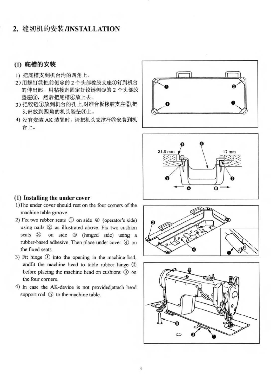
IINSTALLATION
m
~
7t1
rt-J
ll!l
ffl.t .
21-~Hi!.fi~j:§!(D~H,J-11LE1
@$.t~.
J:
.~fiEEi~.ti~~~®.1e
~m~JIQW:®.t.
~::llB;J",
i~1e.fJl.~~tijt.ff@:f(~¥
~fJL
(1) Installing the under cover
I )The under cover should rest on the four comers
machine table groove.
2) Fix two rubber seat.;
using nails ® as illustrated above. Fix two cushion
seats ® on side ® (hinged side) using a
rubber-based adhesive . Then place under cover
the fixed seats.
3)
Fit hinge
andfit the machjne head to table rubber hinge @
before placing the machine head on cusruons ® on
the four comers.
4)
In
support rod @ to the machine table.
CD
into the opening
case the AK-device is not provided,attach head
CD
on side ® (operator's side)
in
the machine bed,
of
@)
the
on
- o
e-
4
Page 10
A.
_
WARNING:
Turn
OFF
s
tart
of
the
the power
sew
in machine.
before s
tarting
the
work
so as to prevent accidents
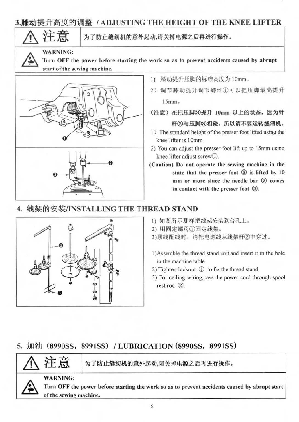
1)
~
i)I
Jt1HrH~llt4Jfi(JtJf-ftti%13t.fJ
2)~~-~-*~~•~CD~~reffi~~~•*
15mm.
caused
IOmm
by abrupt
.
4.
~~o<Jhttps://manualmachine.com/INSTALLING
THE
(tj:~) .tE1effi
~®~
1 )
The
standard height
knee lifter
2) You can ad
knee lifter adj u
(Ca
ution) Do
THREAD
1)
~n
~fjf~JJ
2)
JfJ
1ti1
3)
rm~x
reu
1 )Assemble the thread stand unit,and insert
m the machine table.
2) Tigh
3) For ceiling wiring,pass the power cord through spool
ten locknut
r
es
t rod ®.
lJW®~
ffi~®~~.mt».
is
I Omm.
just
not
s
tate
that
mm
or
contact
in
ft
lOmm
of
the presser foot lifted using the
the presser foot lift
st
screweD.
operate
the
more since
with
the
presser
the
the
presser
sew
foot ® is lifted by 10
needle
1»-..t
fl<J~
~~~~
up
to 15mm using
ing machine in
bar
foot @.
STAND
I
Stf1e;:l~3C~~~Jf:t.fL.t.
~
t~
·
r.J
CD
l!m
frt.
~ ~ ~
~~He
CD
.
rt!
im!~x»Jx~H
to
ftx the thread stand.
®cr
~.
f!i
~~mm
® comes
~
i1.
it
in the hole
~#
.
the
5.
j]u~
&
~
(8990SS, 8991SS) I LUBRICATION (8990SS, 8991SS)
¥.£~
'~
WA
RNING:
Turn
OFF
of the sewing machine.
~r~~~m
the powe
r before
mfl<1a*&
sta
rtin
g the
~~~-~-~~~-fi~~
work
5
so as to
preve
nt accidents ca u
-
sed
by
abrupt
start
Page 11
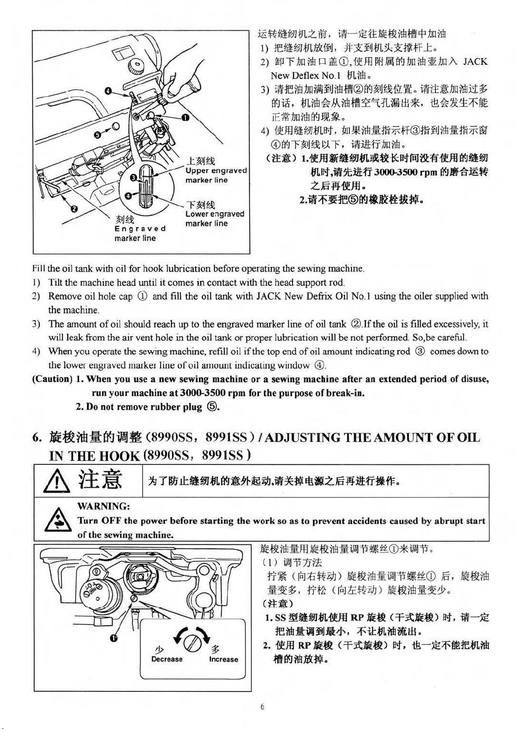
Fill
the oil
tank
with oil for
I ) Tilt the machine head until it
2) Remove oil hole cap
the machine.
3)
The amount
will leak from the
4) When you operate the sewing machine, refill oil
the lower engraved marker line
(Caution)
of
oil should reach up
1.
When you use a new sewing machine
run yo
2. Do not remove
CD
air vent
ur
machine
hook
lubrication before operating the sewing machine.
comes
in contact with the head support rod.
and fill the oil
bole
in the oil
of
at
3000-3500
rubber
plug @.
tank
with JACK
to
the engraved marker line
tank
or
oil amowlt indicating window @
rpm
~••mm~~.
l)
1EfibJJ.t!LfiXfftJ,
2)
lEfJ"""f:br:J~
New
3)
ii:IE1\fJ1Jr:J#UiJ~.m®atJ~
~~
IE
#fJil~~~~.
4)
f~fflU~JJmat.
®atJ"""F~~J~
c
tt~)
D
Deflex No.1
.
m~~M~-~~~~~*·
t.
ifJO
m~t-t
2..6-NifJO.
2.lti~~:IE®£1CJ.~ttt£~.
New
Defrix Oil No.I using the oiler supplied with
of
oil tank ®.If the oil is filled excessively, it
proper
if
lubrication will be
the top end
or
a sewing machine
for the purpose
of
oil amount indicating rod ® comes down to
of
•-~tt••~M~~~
#:J(i
~.t!L
~~f,Uf
iWi
CD,
ft.J=§
llft
1M~
m~.
Ij
~-fl'Lft.
tm*~:l:fli7F;ff®fli¥
I2J.
r,
iRliHr1Jo~.
JT!lmm!~U~¥drt1Blti:ff
,ift]tlltff
after
break-in.
3000-3500 rpm
not
perfonned
an
extended period of disuse,
.t.
1Jil1W
iUUA
ii!ttt~:bll¥!lli1§f;
&~~~~~
. So,be careful.
JACK
1J
rm:!:m7Fw
if.m
e9!lfm
I'J(Jlffil-lg~
6.
lE~rmill¥.JiiAJ.
IN THE HOOK
WARNING:
A
Turn
OFF
of
the sewing machine.
(8990SS,
899ISS)
(8990SS, 8991SS)
the
power before
starting
I ADJUSTING THE AMOUNT OF OIL
the
work so as to prevent accidents caused
··~:!:JOJitE·~·~~~~
(I)
~~
1J ¥t
Decrease
Incr
ease
rr~ <[Q]::b~~)
•
~$
.
rr~<~
(tj:ft)
1. ss
~tutmmu
re
~
:1:\\1
JjJ
2.
i!Jti RP
flt£1CJ?1iJJD(~.
6
JIE~ ( =f~:Jti~)
•
!J,
••
~"~>
RP
•
::f'
by
abrupt
CD
*~~
rm:fl!:
~~~~
••rmg~&
:lti~
c=t=-~Jti~)
11:
m
~
rAt
at,
.
CD
l±i
•
&-
JE~fm1E!11.?1il
~.
••rm
.
Jt-t,
iif-JE
start
Page 12
Adjusbnent
I)
Adjustment procedure
Tighten
(turn counterclockwise) to decrease
(Ca
ution) 1. When using
7.
:Mf~rffiit
OF
&¥£~
&\
(1)
?lli:fit
<D
Amount
of
the amount
(tum clockwise) oil amount adjusbnent screw
adjustment
2.
Never drain
(
OIL
' checked
(OIL
...
~
WARNING:
Be
extre
($UIJH)
of
oil
(oil splashes)
of
oil in the
RP
screw
the
oil in the oil tank
rffi~)
I¥J~f!/JW(8990SS,
SPLASHES) IN
~~~~~~~~.~T~~A~$~.
mely careful
by turning
?Of!V..1Jf!l
How
confirmation
hook
it.
hook(hook
up
to
the
about
the hook
to
con firm
at
is performed with oil
CD
for
dry
head)
minimum so
even
as
when
to
8991SS) I ADJUSTING THE AMOUNT
the
a hi gh
paper
THE
operation
the
HOOK (8990SS, 8991SS)
of
spee
d.
amount
®
amount
to
increase the amount
for
the
reduce
RP
hook
the mac
of
oil (oil
Position
adjus
SS
type,
the
oil
(hook
~-~-~.~m~~~~~~
hine
splashes)
to
confirm
bne
be sure
amount
for
dry hea
since
the
nt screw
of
the amount
amount
CD
oil
in
to
loosen
in the hook.
d) is used.
of
oil
.
the hook, or loosen
the
oil
amount
.
of
oil has to be
-
(oil splashes)
E
~
E
n
•
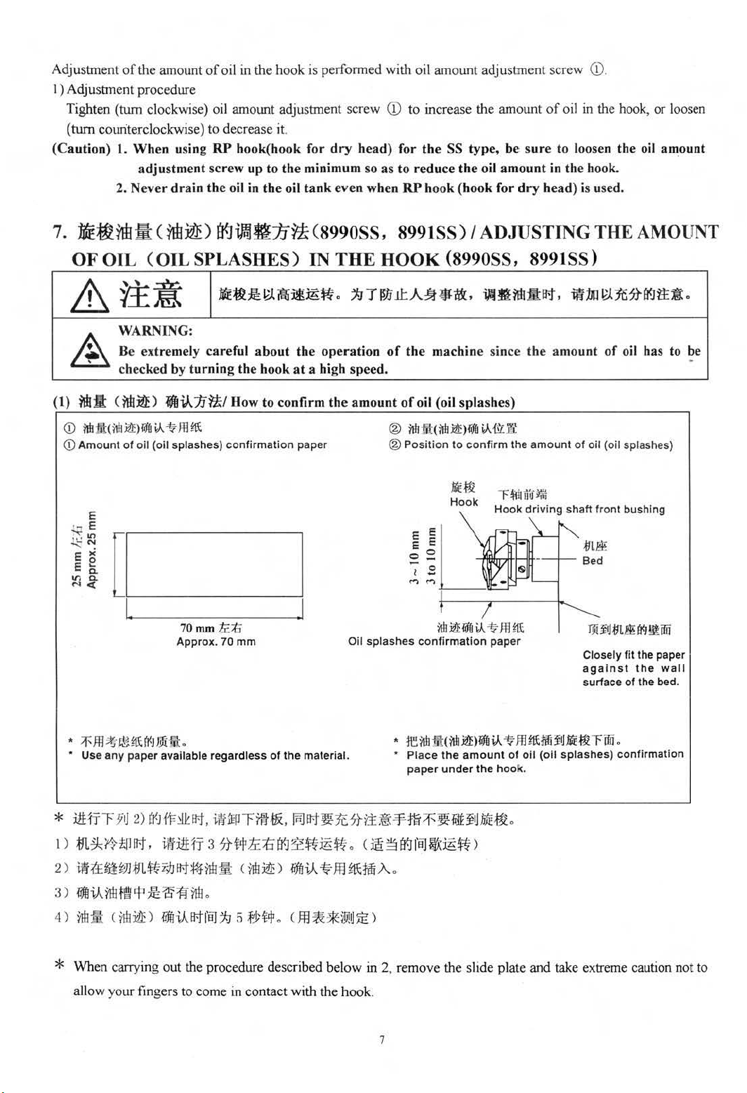
• Use
* iiHJ'F 111 2)
I )
z)m~umm*~B1~~~<~~)•~•m~•A.
3)
4)
[1!-------~
70
mm
ft.;f;
Approx. 70 mm Oil
>Fffi~~~(
tfl
~lt!rJrr.t,
·~nlltfN9'~~~1r!
~lt
rl:
F-JJ1
any
Hil:.
paper available regardl
tr'.lft~B1.
i!litHr 3
Offiil£)
1iffl~ftt
ess
illffEIJrffi
?t~li:;ba<J~~iE~.
J.
i'8J
;9 5 .fy~cp.
of
the
material.
:tJX.
~ftt~JE
Oll~B
splashes
•
•
?tr£g.:p11J:f'!H
C
~3a<Jf8Jf.i::iE~)
lt~Y!tl
~)
~~
Hook
nn~liffiV-
confirmation
reit!lill
<nn~>li1HV-
Place
the
paper
under
~
T~111u·f;1,t
Hook
-
~m~
paper
amount
the
hoo
t¥1JJiJE~.
driving
~
ffl
fft:tilif'1..16Ett
of
oil
(oil
k.
shaft front bushing
fit the paper
Closely
against
surface
the
of
the bed.
rffii.
splashes)
confirmation
wall
* When carrying out the procedure described
allow your fingers to come in contact with the
below
in 2, remove the slide plate
hook
.
7
and
take extreme caution not to
Page 13

I) If the machine has not been sufficie
approximately three minutes.(Moderate intermittent operation)
nt
ly warmed up for operation, make the machine
run
idle for
2) Place the amount of oil (o
operation.
3) Conftrm that oil exists
4) Confirmation
watch.)
(2)
7111:1!:
(
of
711!~) ~*~1l/
Splashes
in the oil
the amount
lAME~~~
of
/
: 1 v
·
V:
' '
' '
: i
.1.
0.5-1
itb:ID:
~
iate
amou
~ ( tj\ )
nt
of
Appropr
il
splashes) c
tank
of
oil should
Samp
le showing the appropriate
l±l
:liE
B<J
from
mm
oil
$tb
the
(small)
oil
onfmn
be
hook
ation paper under the hook while the sewing machine is
completed
in
ftve seconds.(Check the period
amount
1 )
li:
00
t
'F
jj:);:::tj
(
~~ct
r5~~11i~£.)
2)
~ik
O!b
I )The amount
should
processes. Be careful not
decrease the amount
of
oil is too small, the hook will be seized (the hook
of
oil
#ttH~
!l
~
#Jtl
-fJH/ff
~ ~ 1t~
J
JQ~(f;ty
~~.~-~--
~)
be
.
(~~).~ti1$~.~
JSY1
ifH.A
3 (
J;:
0 5i0
of
oil shown
finely adjusted in accordance with sewing
in
the samples on the left
to
excessivel y increase I
of
oil in the hook.(If the amount
of
if.j
.tW
l1it
• m
:1:$)
5£~-ft.
time wi
t.E
~
.
th
/F
in
a
Jl:
M.~~~~l±l*rfJith
Splashes
__jj.
)tb:!i~ ~ <;~)
Appropriate :amount
s.m#a<J~~:!Jf!
...
&¥±~
~
~
WARNING:
Turn
OFF the
of
the sewing machine.
of
oil
from
the hook
I -
1.5
mm
of
oil
(large)
I ATTACHING THE NEEDLE
~Tm~•m•~
power
before
starting
will be hot).
sewing product may be stained
2)Adjust the amount
amount (oil splashes) should not change while
checking the oil amount three times (on the three
sheets
of
paper)
If
the amount
of
of
oil is too much, the
with oil.)
oil in the hook so that the oil
•*m~~~•*•~~~•ff•~·
the
work
so as to prevent accidents caused by
abrupt
start
8
Page 14
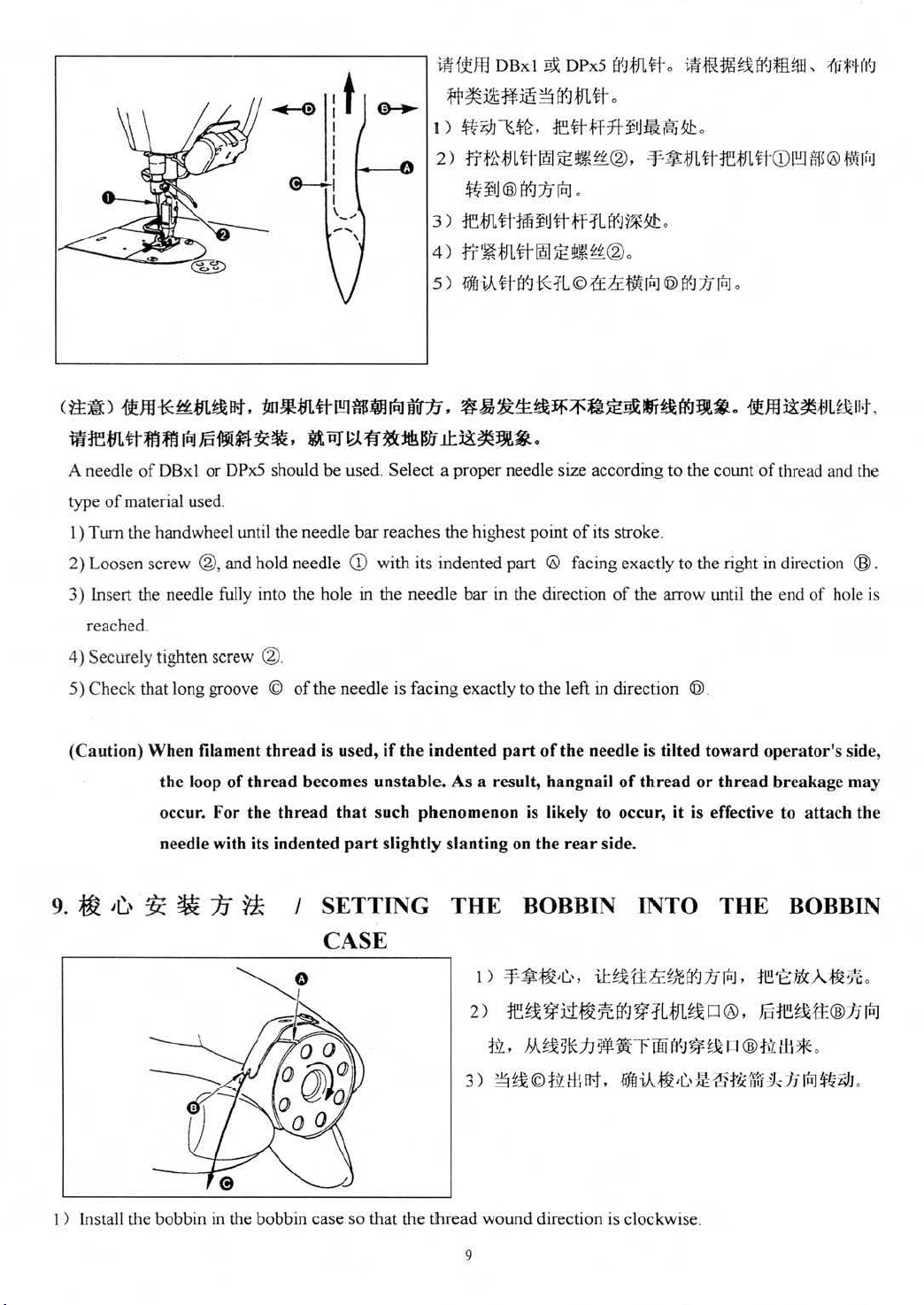
~Wftffl
DBxl ~ DPx5
~JlJL#.
i~.ftH~~B'~fliWJ,
1'fi*'HI(J
:t
~
I
I
I
I
~
I
I
,_,.
c~:i:) 1fffl*
•re-mtt-~~~~••~•.
A needle
type
of
I)
TWTI
2)
Loosen
3)
Insert the needle fully into the hole
~.m~
a:t. W~*m*[!!J~.iJinlmrn.
of
DBx I or DPx5 should
material used.
the
hand
wheel until the needle
screw ®,and hold needle
~~~w•*•~~~••
be
used.
Select
bar reaches
CD
with its indented part @ facing exactly to the right
in
the
:fr~:i*
1 )
2)
3 )
4)
5)
~ilt
~
({-]
,fJL
* 0
~Z))JlS~,
rrt~;fJLHm!}:Et~f'i'®,
~
ilj
:Jet
JL
tr
n=~tJLtt-~~t~~£®.
fiffliA#B<J*1L©1£~fY'iia.J@B<J/Jr~
~:&-~~~:Ef::f'~~~*f~(J<Jl:l•·
1E.#ff7f-$rJifkrl~B!.!:
®
({-]
1J
laJ
0
ffi $
1j
*
.jf
1l
fj{J
~ ~
o
-¥~H1LtHemti"CD[!!Jfl'
0
o
1fffll3:~MJL
f
)®~
~11H,
HiiJ
o
a proper needle size according
the highest
needle
bar
point
of
in the direction
its
stroke
of
to
the count
.
the arrow until the end
of
thread and the
in
direction ®.
of
hole is
reached.
4) Securely tight
5)
Check
(Caution) When filament t
9.
~
~~'
en scr
that long groove ©
the
loop of
occur.
needle with its indented
!i.
~
for
1J
ew
®.
of
hre
thread
the thread
~
the needle
ad is use
becomes un
that
is
facing
d,
if
the
stab
such phenomenon
part
slightly slanting on the
I SETTING
CASE
exactly to the left
indent
ed
part
of
le. As a result, hangnail
is likely to occur, it is effective to attach the
THE
2)
3)~~©~ili~.
BOBBIN INTO
I )
¥~~~C.·, iH:
re~~rl~:Jift-J~:t
152,
h\?2.Bt0J
in
the needle is tilted toward
rear
side.
5!li
direction @.
operator
of
thread
or
thread breakage may
THE
H!lr:~JtB<J/Jr:;J,
LtJL
~IJ®,
~r
rnHI
0
~ ~
®iA•~~~~m~h~~~
1~E;iD{.A;f3l
m1~~1tt:®hltrJ
I I@
.fil.
's
side,
BOBBIN
:/6.
/11 *.
o
I)
In
stall the bobbin in the bobbin
case
so
that
the
t!hread
9
wound
direction is clockwise.
Page 15
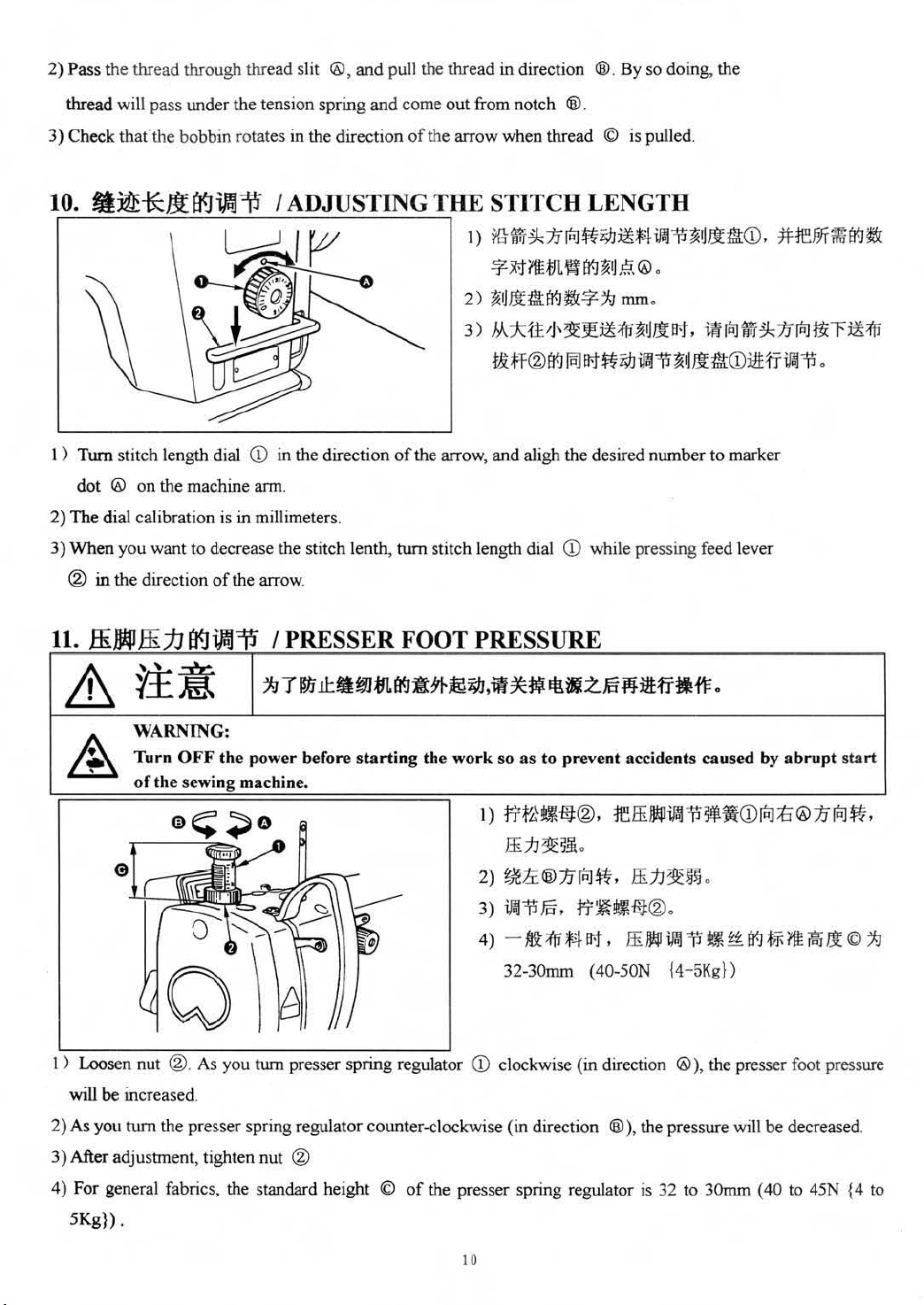
2) Pass the thread through thread slit
®,
and
pull the thread in direction ®.
By
so
doing, the
thread will pass under the tension spring
3) Check tha
10.
I )
Tum
dot
Th
2)
Wh
3)
® in the direct ion
fthe
bobbin rotat
ff:it!
*ll
a<JiAJ
stitch length dial
® on the machine arm.
e dial calibration is in millimeters.
en
you
want to decrease the stitch lenth,
of
es
in the direction
iJ
I ADJUSTING T
CD
in the direction
the arrow.
and
come
out
from notch ®.
of
the arrow when thread © is pulled.
HE
STITCH LENGTH
I )
illWrf
~
:IJ
rtJ
~~i9J~:M
-*"
M
?tUJL
~
(f.J~rL~.
2)
~!Jf.ffiEr-1~-*"~
3)M*tt~~
•H®(f.J~~~i9J~~~~-CD~~-~
of
the arrow, and aligh the desired number to marker
tum
stitch length dial
~~~~J.t~.-rtlft~:IJ~~~~~
CD
while pressing feed lever
iP.li5
®.
mm.
~!JJ.t
fit
CD'
:tHEJi.JT
~
.
Et-J
~
11
.
JliJJ14J
.ffi
jJ
a<J~Ti
£, WARNIN G:
_
Turn OFF
of
the sewing machine.
I)
Loosen nut ®.
will
be
increased.
tum
2) As you
the presser spring regulator counter-clockwise (in direction
I PRESSER FOOT PRESSURE
the
power before startin
As
you
turn
g the
work
presser spring regulator
so as to prevent accidents
1 >
n't.HJ-e:®.
ffit.J~
2)
~
le®1J~~.
3)
ir.J~€.
~--~M~.
32-30mm (40-SON {4-5Kg})
CD
clockwise (in direction
reJI!J141•
5!
.
ffijj~~~
:rr~t'-HJ®
ffi
!J141•Ti~*Et-J~m•J.t©~
®),the
caus
ed by
abrupt
Ti~J(CD
.
.
®),the
pressure will be decreased.
rtJ
:ti
presser foot pressure
sta
®/Jrtl
~,
rt
3)
After adjustment, tighten nut ®
4) For general fabrics, the standard height ©
5K
g}).
of
the presser spring regulator is 32 to 30mm ( 40
10
to
45N { 4
to
Page 16

12.
_t~~~:JJ~
I THREADING
THE
MACIDNE HEAD
~
~
¥±~
.'
~
WARNING:
Turn
OFF
the
of
the
sewing machine.
~T·k~-m~a*&~~~-~SZfi~-~-~.
power before
starting
the work so as to prevent accidents caused
0
<
tl:
>
(Note)
by
abrupt
::ftJMelft~!lli
Do
not
pass this
thread
through
section().
O
start
$
11
Page 17
13.
~~~~
1J¥!
I WINDING
THE
BOB
BIN
THREAD
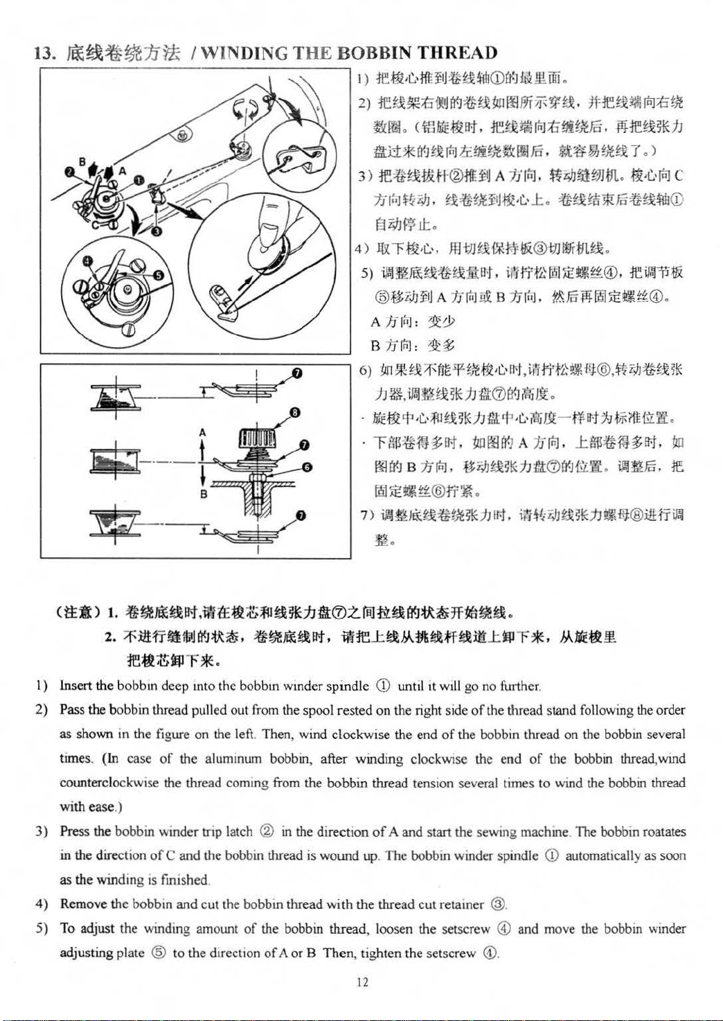
I)
le~·L.•
2)~~-~-~~~~oom~9Y.~re~•~~~
ff
U~:¥1:~!ffh
<D
tf.J
ibiill.
iiD
.
~~.<m~~~.~~~~~~~Fc.
~i1*1'f.J~xlnl
3)
1E~~1£#®-Mf..flj
1Ji
nJ$
!iliiJ
§
MW
4)~~-~.
s>~•
6)
-
-
7 )
~~$~hl~.~~~~~~~®.re~~•
@-~~A~~~B~~
A
:1JrQ:J
=
B
:1Jrnl
:
1m*~:;
)J
~5.
illft~~
~-~~~~*h•~~n&-n~~~m&~
~n~w~~. ~OO~Anlnl . .te~mJ~.
~~B:1J
~~t~f:~®rr~
ir.l~J~J&;ffi~~~lUJ
.t
df!~~m~Fn.
A 1iliiJ,
,
~x~t~jiJ~·L.·.t
~~~HJHxT.)
~4JriiWJt11.
.
~tHi!i'~Uci~~H!lJ
ll:.
mm~~M•®
~&
~~
Ffielf-m-!3l·t·rt-t,i~f-i't~t~-f{t®,tirJJ~~x5K
~lUJ
:W.:
(J)
i¥J
inJ,
8~Y~h·~~&•.~mfi.e
.
IM',
~~m~
.
~ffi~~~-~@.
~·~I~
.
iat~i"JJ~5~1J-HJ;
~~~*h
.
.
~·L.·~
@
C
~
.
~
i8:tr~
••
<t:EA)
I)
insert the bobbin deep mto the bobbm wmder spindle
2) Pass the bobbin thread pulled out from the spool rested on the right side
as
times.
counterclockwise the thread coming from the bobbin thread tension several times to wind the bobbin thread
with ease.)
3) Press the bobbin winder trip latch
in the direction
as
4)
Remove the bobbin and cut the bobbin thread with the thread
5) To adjust the winding amotmt
t.
$~~~1Pt,iiHE;ti45lt'l~*iJfl®Z.raJtt~(J(J~~1f1tii~~.
~
~•ff•~~~~.•~•~~Pt.•re~~Mm~~~-~~~*·M~~•
re~~lll
shown in the figure on the left. Th en, wind clockwise the end
(In case
the winding is fmished
-
F*·
CD
until it wi
of
the aluminum bobbin, after winding clockwise the end
® in the direction
of
C and the bobbin thread
of
the bobbin thread, loosen the setscr
is
wound up. The bobbm winder spindle
of
A and
stan
cut
ll
go no further.
of
the thread stand following the order
of
the bobbin thread on the bobbin several
of
the bobbin thread, wind
the sewing machine. The bobbin roatates
<D
automatically as soon
retainer ®.
ew
® and move the bobbin winder
adjusting plate
@ to the direction
of A orB
Then, tighten the setscr
12
ew
@.
Page 18
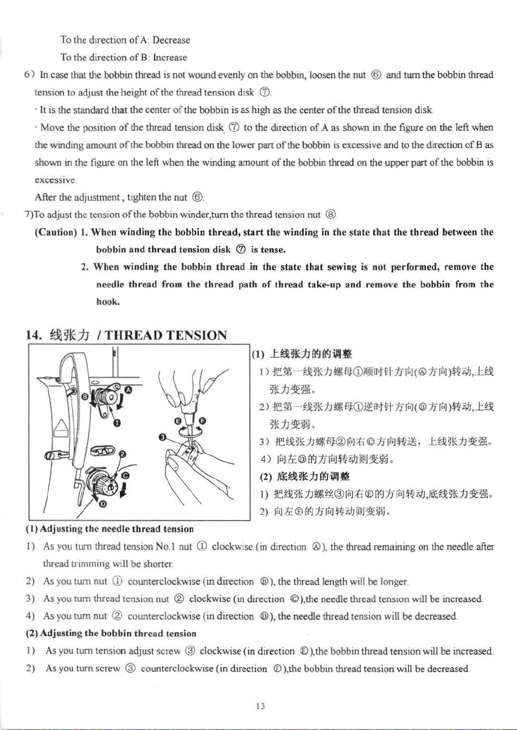
To the direction
of
A. Decrease
the direction
To
6)
In case that the bobbin thread is not wound evenly
to
tension
·
It
· Move the position
the winding amount
shown
excessive.
After the
7)To adjust the tension
(Ca
14.
adJust the height
is the standard that the
in
the figure
adjustment.
utio
n)
J.
Wh
bobbin
Wh
2.
needle
hook.
~*.7J
I THREAD TENSION
of
B: increase
of
the thread
center
of
of
the thread tension
of
the bobbin thread
on
the left when the winding amount
tighten
of
en w
inding the
en
winding th
the
nut @.
the bobbin winder,
and
thread
e bo
thread from the thread path of thread take-up
tension d1s
the
bobbin
disk
on
bobbin
thread,
tension disk
bbin
on
k 0 .
is as
high
(J)
to
the direction
the lower part
tum
the
thread tension nut ®.
start
(J)
is tense.
thread
in the s
(I)
the
bobbin, loosen the nut @ and
as
the
center
of
the thread tension
of A as
of
the bobbin
of
the bobbin thread on the upper part
the
winding in the state that the
tate that sewing is not
_t~~j](fj(f]i.flfl
shown in the figure
is
excessive
and
and
performed,
remove the
tum
the bobbin thread
disk
.
on
the left when
to the direction
of
the bobbin
thread
between
remove
bobbin
from the
of
Bas
is
the
the
(t) Adj u
I)
2) As you
3)
4) As you
(2)
I)
st
ing the n
As you turn thread tension No.I nut
thread trimming
turn
As you
Adju
As you
turn
tum
sting the bo
tum
eed
le
thread tension
wt
ll
be
shorter
nut
CD
counterclockwise (in direction
thread
tens
tOn
nut @ counterclockwise (in direction @ ), the needle thread tension will
bbin
thr
ead tension
tension adjust
CD
clockw1se
nut
® clockwise (in direction
screw
® clockwise (in direction
1)
:te~-!x5~JJ~~~
5*JJ~5!
2)
rem
5!E.7J~~~
3)~Y*hS~®Iul~ChluJ~~.
4)
[Q)le:@a91JrR'J~z;lj)J!IJ*~~
(2)
Ji£~~11
1 >
retx5*
2)
[ti)
(in djrection ®
®),the
.
- t
..
BtEJJ~~Q)j!ft1tUflnl<®7rluJ>~rJJ.J:~
.
(fj
.:7J
~
£ ®
ft-J
}J
),
thread length will
©),the
needle thread tension will
®)
,the bobbin thread tension will
<D
K~rr·tvt-1JrtJ<®7rlnl>*zJJ.J:t~
J:Y*.7J~~.
.
iAJff
~~®inJ;tJ
[ti)
t~fJJ)J!Ij~~~
the thread remaining on the needle after
®
be
(j{J
1i
o
longer
rtJ
~
M
be
decreased.
,JtHx
5*JJ
be
increased.
be
increase<i
~5,;
.
2)
As you
tum
screw
® counterclockwise (in direction
13
®),the
bobbin thread tension will
be
decreased.
Page 19

15.
15!~~-
( 1)
Changing
the
/TH
stroke
READ TAKE-
of
thread
take-up
UPS
spring
PRING
<1>
Jf
i&~tifi.JICDacJrrf£111
1 >
rrt~~s~JJ
2)
re~~~JJH®~:ti®tr.J
3)
rfil~®f(~1Jfnl-1:1i;I:JJill
(2)
Jfi&~tifi~•CDB<JffiJJB1,
1)
rrt~~
2)
rrt'~~x5lCJJH
3)
fEJ~
4)
rPJ1L®f(-J1JfriJ~l;JJ!Jli
f:l
~~~~~~®.
f
(~1J~~i;I:JW1J~
j~;J'.
ri:
~~~®Jrrf~*.1J%~(ffi.1lf)
!i!
l~t~~@itHfif~~
5*
fJ
ff@~
;(:J
@
(f.]1J
~
J~~.
CD
I) Loosen setscrew ®.
2)
As
you tum tension post @ clockwise (in direction @),the stroke
of
the thread take-up spring will be
increased.
3) As you turn the knob counterclockwise (in direction ®),the stroke will be decreased.
(2)
Changing
the
pressure
of
thread
take-up
spring
CD
.
:k.
@.
.
~i;I:J
D!IJ~~!Ji
.
I) Loosen setscrew
2) Loosen setscrew
(
~,and
@.
remove thread tension (asm.) @.
3) As you tum tension post @ clockwise (in direction @), the pressure will be increased.
4) As you tum the post counterclockwise (in direction ®), the pressure will be decreased.
(ti:Alt)
JK8991-DS ,
~~. ~fi-J<iPI!fB<J~~~.
~~fi-·1PI·~~I¥J:1!1JJE
timzM.
!l•1ia<J~~rrfl5:J:;J'B<J~~fli!J3'&*~4.
.
m~~~~~nu~.m~~~~~~M
:!&:
12 ili * .
When the thread take-up
midway, th
tension
DF
:#l~f;§~*ffl
~~••£~$a~~·~*~£~~.ra$a~~.
1J
~£:
~1t=f
J:tttftt,
tt~~~~t:Jifi,
fdfti.\~~--B<JffiJJiPI!f
~-!i:B<J
-ftffl:bo?\bldfitl:ttf,
IT~.&!ie~ll!~~~.
.E
'
jE_tf;l(R]®/JrtiJtil±I.Ta'
~~~~~••B<JffiJJ.~jr.m
-
JN:-11Jt4
t0-J3mm
ii:;(:J~~~.
X
•
~E~~)9i-liz;IJ~~HN:J5
•
The
thread take-up
up
to
the last.
of
read
the
is
fed
thread
spr
out from
take-up
ing moves
0 since the
spring
is
O
up
to
high.
~~~~f;l-~1,\l!fa<J
0
spr
ing works
~JA<;Yft
•
14
Page 20

(Caution)
For
the Models
JK899lDS
and
-DF,
the
fully-dry hook is
adopted
. Comparing with the sewing
machine using
thread
increases. As a result,
To
jud
works
the direction
does not
stroke
general
16.
m
~
ff
&it~
A
--~
WARNING:
Turn
of
the
the
existing hook, the sewing machine tends to be affected by the adjustment
take-up spring .
ge
the
work
of
up to
the
last before needle
of ® after
work
up to
of
the
thread
fabrics, a
1J6
~I
take-up
stro
B<J
~rm~~•moo•*&~~*•*~~~~-~~~-
OFF
the
power before
sewing machin e.
If
the
thread
thread
the
the
ke
breakage,
thread
last,
of
~
tak
e-up
thread
the
pressure
decrea
spring
10 to 13 mm is proper.
is excessively small,
T-i
I ADJUSTING THE THREAD TAKE-UP
starting
take-up
balloon stitching etc. may occur.
spring,
of
se
the
spring
confirm
is pulled
the
thread
pressure
does
not
whether
out
from ® when pulling out needle
take-up
of
the
the
spring
thread
spring
STROKE
the
work
so
as
to prevent accidents caused
of
work
sufficiently,thread running
or
not the thread take-up spring
thread
ha s been performed. When it
take-up
does not work properly. For the
spr
ing. In addition, the
by
abrupt
start
the
in
l
2)•~•M~.re~~-oo~~®~~~~~.m~
3)~~-ro~~~©~-~~~~~~~~~~m
I)
When sewing heavy-weight materials, move thread guide
of
thread pulled
2) When sewing light-weight materials, move thread guide
of
thread pulled out by the thread take-up.
3) Norm ally, thread guide
17.
:tfl.#
&it~
--~
out
by the thread take-up.
ID
is positioned in a way that marker line © is aligned with the center
w.tt{f[•B<J~~
I ADJUSTING
~Tm~~•mooa*&~~~·*~~~~-~-~-
)B~~M~.e~~-
!!~*·
1iE:l
~'J'
.
CD
to the left (in direction
CD
to the right (in direction
THE
NEEDLE STOP POSITION
ID~~®~~~
®)to
increase the length
®)to
decrease the length
of
8~.m~
the screw.
WARNING:
A
Turn
OFF
of
the
sewing machine.
the
power before
start
ing
the
work
so as to prevent accidents caused by
15
abrupt
start
Page 21
\
(1)
W~
J§
a<J~
11:-&
~
1 )
t=r-
r1Ur~
m
tt
w .tt
lliit:&&:
Er.J
8
~
~J.
~ ® -i~ll-JEr.Jmft.
2)~mtt~~~~W.t1:1flit.~~-~ill.~*Rffi
l:rn
:iJHf
iJWf.i
•
A. lti
J ©
EB
1J
r~
:tt
i;IJ.fJl
B.
[DJ©Er.J1JJriJ
~i9.Jfil#
m.tt7'r
~t·
f!P
.UJ!l:
f¥ll:fi:iR
4HB~u
litr.
.
£ ®
~
~.tt
ctt~)
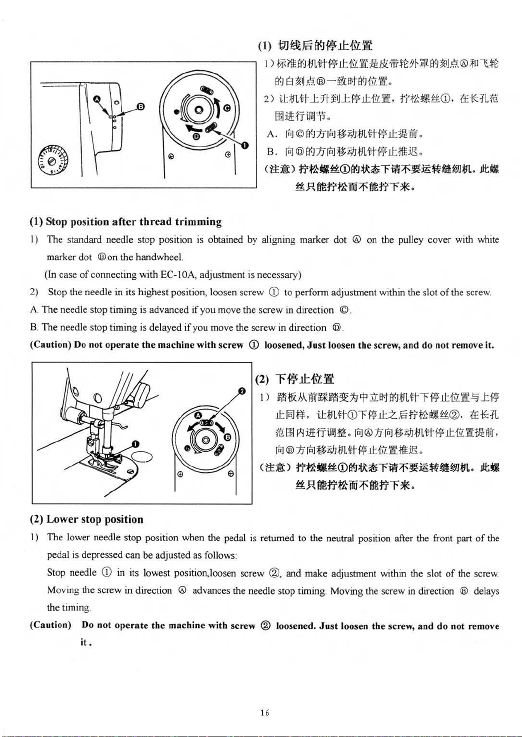
(1) Stop position
1)
The standard needle stop position is obtained by aligning marker dot ® on the pulley cover with white
marker dot
(In case
2) Stop the needle
A.
Th
B. The needle stop timing is delayed
(
Caut
of
e needle stop timing is advanced
ion)
Do
after
thread
®on
the handwheel.
connecting with
in
its highest position, loosen screw
not
operate
the
trimming
EC-1 OA, adjustment is necessary)
if
you move the scr
if
you move the screw in direction ©.
machine with screw ~ loosened, Just loosen the screw, and do n
(2)
\)
~~•*~~~
*
.R
fm~~ffii
ill
to perform adjustment within the slot
ew
in
direction ©.
"f
w
11:
-&•
~~Mlitr~~~~~
.tt~~.
Mm
JriJ
®
ftmttill~W
~•fi~•
1J
JriJ
• M
{JI.
~~
~~ ~
~
fm
tr~
*·
ft~~m
.tt~~tr
.[DJ®~Jril
tt-~
•i9.Jmtt~JJ:1fl
.tt
lli:rt
m
~~~~m.
of
the screw.
ot remov
tt~w.ttm•~~
~•~®.~*~
j[i.
~•
e it.
~
••litr
.
ctt~)~
(2)
Lower
I ) The lower needle stop position when the pedal is returned to the neutral position after the front part
pedal
Stop needle
Moving the screw
the timing .
(Caution) Do
stop position
is
depressed can be adjusted as follows:
ill
in its lowest position,loosen screw
in
direction ® advances the needle stop timing. Moving the screw
not ope
it.
rate
the
machine with screw ® loosened.
®,
16
~•* ~
*
.R
fm~tl
and make adjustment within the slot
~~~~~~~
ffii~fm
Just
loosen the
~ ~
*.
screw,
~~~mm
in
direction ® delays
and
do not remove
of
the screw.
.~
of
•
the
Page 22

18.
~~ff7J
WARNING:
A
Turn OFF
lUff~
the power
of the sewing machine.
I PEDAL PRESSURE AND PEDAL STROKE
before starting
the
work
so
as
to
(1)
•*~il.ffi.1J
1)
~~~rf~~.ffi:f.Jifnri
2)
~5!'fl.JH3
3)
~
jiJ
:tJ
'ffiiJ.ffi.:f.J~Ao
(2)
•*~~.1JB<Jilld~
I ) ffl ~
2)
3)
(3)
~ii~H®:ti:~¥
~
iJWiJ
rr~iJWf.i~H
trt~t~HBS.JJ~~o
•*~·trfla<Jilldl!
prevent
accidents caused by a
brupt
(t(]i}ld~
'
H!'fl~CD:itHTiiW:P
~¥1J
tt:1J!tlffi:f.J~~o
~ H ®
i'iJ
I2J.
1tHr
.ffi.iJ
~A
o
1J
ti:iJ!
tl
l¥JfLI*J,trf:i~'J'.,
iJal
i:l
0
o
start
(1) Adjusting the pressure required to depress the front
I) This pressure can be changed by altering the mounting position
2)
Th
e pressure decreases when you hook the spring on the left side.
3) The pressure increases when you hook the spring on the right side.
(2) Adjusting the pressure
I) This pressure can be adjusted using regulator screw
2) The pressure increases as
3)
The
pressure decreases
(3) Adjusting
The pedal stroke decreases when you insert connecting rod @ into the left hole.
the
pedal stroke
as
requir
you
you
ed to depress the back
turn
the r
egu
lator screw in.
turn
the screw out
®.
part
of the pedal
of
pedaling pressure adjust spring
part
of
the pedal
CD
.
17
Page 23

19.
~:tfiB<Jlm~
WAR.'IING:
&.
Tu
rn
of
the sewing machine.
I ADJUSTMENT
OFF
the power before
start
OF
THE PEDAL
ing the wo
rk
(1)
(.oJ
so as to
it~
ij'l{
prev
ent accidents caused by
ff(fl~~
J.;
:t.nt•J.fti;/J~
~
i!Wil
{&
@.
abrupt
il
:
fl.J~:f1
1
M.ff
Q)
start
.fll
20.
~
:tfi
~f'F
I PEDAL
OP
ERATION
.ia:1~H®PX;
(2)
l?lti
1)
if.'.l1i:ii~H(I'~
2)
t-rr~u~r-TJt:#.~.®.ttiVJ:itf~H®*ffw.l"'P
-
JHx.
~(I(]
1tJ
1l
K&f!Prif!;J.c.l(~
i'J'ltfii'fJ
(1) Insta lling the connecting rod
Move pedal @ to the right
arrows so that motor control lever
® are straightened .
rod
(2) A
dju
sting tbe pedal angle
I)
The
pedal tilt can
length
of
the connecting r
2) Loosen adjust screw
connecting rod ®
(1)
~~:(:f
I )
rtl
ntr~~
2)
rrm~rlwr~~·::.kJ~it~~J
•mH~~.
3 )
*£~r~Ul!H&r~
p.}
JU
4
t&~d1:
ff!UM&/lJ{l':it~~JJ
~8M*~€~~i!UMl
m
.
be
.
~@I~
or
left as illustrated by the
CD
and connecting
freely adjusted by changing the
od
@),
and adjust the length
®.
®.
<f§.
~.
mm
p;~
.tt
~
< m 'ft
ll;
#JJJ[
.
.
~1E
r §l9J
..t
w
Ltsx"F
of
4 )
~·JRT~~tR::J;JtJHxfJJff®
*
f~t
iJ
li
zvJIEJWi.W:f~~f:I:B1
~ff~. ~m~~~~~. ~ffi~~h~*®.~~
~~
~u~
:t&
~
t;J
~l
Z;IJ
11=
.
•
~~l'f]
•M•
-~m
·~m
(I)
The pedal
I) The machine runs at low sewing speed when you lightly depress the front part
Fl
Z;JJf&tlfli!:f,
••m~~i!U~~~Fom~•~••m.m~~w~.
mw~~~~~~~~~~~@m~m~~~~~
.m~~m~~~~~z~.~•mft®m~~.
is
operated in the following four steps:
.Je~:tJijS@I
!:f
Jl:ifl~D!
IJ~iHJJ.#L
f~JfiHs*Fof¥
.
~tt~a-~••·
18
11
-.•
o
.
{Ef¥
rt.#rt;HxZ.fnJJ~Jm
of
the pedal ®.
Page 24

2)
The machine
automation reverse feed stitching
feed stitching.)
3)
The
machine
4)
The
machine trims threads when
*
If
your machine
thread trimming
if
you further depress the back part, the thread trimmer is actuated.
nms
at
stops
(with its
is
provided with
step. The
high
sewing
needle
presser foot goes up
speed
has
up
you
the
when you further depress
been
preset,
the
or
down)
when
fully
depress
Auto-lifter , an addition
the
when
the
machine runs at high
you
reset
the
pedal
back part
you
of
the
pedal ®.
step
is given between the machine stop and
lightly depress
front part
speed
toit
s original
the
back part
of
the
pedal®.
after it completes reverse
position©
of
the pedal @,
(If
the
.
and
• While machine
sewmg.
•
The
machine will perform normal thread trimming even
following high
•
The
machine will completely
immediately after
• When the machine stops with its needle down, and
the
pedal
21. itl
fM!
or
once
.
:=f-l;t]
in
automatic back sewing,
low speed
the
fflj
it
sewing
perform
machine
started
I ONE-TOUCH TYPE REVERSE FEED STITCHING
if
the
.
thread trimming even
thread
trimming action.
MECHANISM
pedal put
if
(1)
I)
2 )
3)
(1) How to
1 )The moment switch lever
2)The machine performs reverse feed stitching as long as
3 )The machine resumes normal feed stitching the moment
to
the
neutral place, machine will stop after back
if
you depress
if
you reset
you want to bring
ttffl1ir!
19:
"f
**1£
ffCD,
1-E
tiC
F
0'~
r11
I'BJ
ilHr
-=F--t~Jf
performs reverse
the
switch lever is
the
switch lever
SLilP~1J iE(Q]~g~J
operate
is
the
back
part
of
the
pedal immediately
the
pedal to its neutral position
the
needle up,depress the back part
til~JJfJU'L
{~1)
feed
sti
held
depressed
released
§jj o
tching
.
f!
P
(J!Jfiit
0
J
o
CD
is pressed, the machine
.
.
of
(2)
1f;X:
~[§!)
Heigh
t
of
the
switch
&¥±~
A
I)
2l fF
~~
;X:(l)if
'~
WARNING:
Turn
OFF
of
the sewing machine.
~~-~®
2
t~ffi:
~T~~~
the
power
. k~BM*~~~~~-~
'I'6T
before
~ffffL
~moo•*~
starting
the
~~~-~
work
so
0
19
~~m
as
to prev ent acc idents caused by
~-~~~
0
abrupt
start
Page 25

3)
~:fe7l
I)
Loosen setscrew ® and move the switch itself up and down to adjust the height.
2)
Switch
3)
In
machine head and lower switch base
•
r&WHf~
The following functions can be performed by one-touch operation using optional switch (23632656)
(I)
Needle up I down compensating stitching ••• Every time the switch is pressed, needle up/down compensating
stitching
(2) Back compensating stitching
speed (This is effective only when the constant-dimension stitching pattern is selected on the
(3) Function to cancel once reverse feed stitching at the end
automatic reverse feed stitching
(4) Thread trimming function
(5) Presser lifting function
(6)
:;X:CD
tr.Jlli:J!
CD
can be used in two positions by turning
addition, when you desire to lower the position
( ~
is
performed.
One stitch compensating stitching •
performed.
:f'fF
~rr-t.
?'~~~)
••• When the switch is pressed, automatic presser lifting can be executed.
i~rrtlf'~WJ;fJL'ffiHitf.J~~t~~®.
@ .
I Optional switch (separately-available)
f.t
P~
:iM!'q
7f
( I )
~l~
tt-H~~~JJ
< 2 )
fill
f'.it
CP-1600
(3)
~a*f~J~
t1lz!f)(
¥~
(4)
t]J~r)Jfi~
<5
>
EE
iltilfn:
(
6)
I
tt-1H~~~JJ
••• Every time the switch
at
the end
••• When the switch is pressed, thread trimming is performed.
of
••
Every time the switch
~-Fff*~®o
it.
of
switch
~
< 23
:fH~
f'.ii
f*ft~J::i2H4!7
1
0
•••
fi-
J;tJti~
sewing onJy can be canceled once.
CD,
loosen setscrew ® located in the back
63
2656 )
•••
~JJ
ix~WlrJJee
~7f
•••
•••
is
CD
~;~.
r
tf.J
J;IJ
'BJt~-~ff:'ldlH
••
•
tJ
~-
~R
•••
:1E
Fo:iittY.W~
~:rF~Fo
ffJti(
-
(X;Jf~iiHT
pressed, reverse feed stitching
of
sewing ••• When the switch
is
pressed, one stitch compensating stitching
f
J:'
?~
7f
* .
\t-~11l~~~IJ.t~~~
~7f7t:zFo.
o
ffilltil
E!
Z9Jtt1t
ti~
ilf
t;t
JfJ
!f!-
M ~ :i1Hr
-F
~
!f.t~Z;!J{'\=
t;t
f~
.i!UiHr
r--~tr.Jra*
0
1
ft-;~~~§.i!~.'lJ
fill
o
)
o
0
f:ii
o <
CD
is
performed at low
CP-1600 panel.)
is
pressed,
of
the
o
9-i:f
{E
E!
Mf~J~
.
the
next
is
•
~~{tf:7f~I¥Jlttll
&¥±
A
~
"'liTh
WARNfNG:
Turn
OFF
of
the sewing machine.
Connection
~T~~~~
the
power
befor
oftbe
e s
optional switch
m~
•*m~~~**~zFo~*ff~~o
tarting the
iW
~JJ
t;t
lnsert the cord
connector
polarity).
The pin is provided with the inserting direction.
protruding portion @ upward.
work
so
1e:i2tw:J14
®.
iw
re~ur,®®WJ
nr
:EI
7f*
=~~
CD
20
as
to preve
B'~
Efit•,Hru
<
15!:
1=Ht>Z
J:tmA.o
of
the optional switch into ® and @
coming from the machine head.(There
Af
tu.
nt
accidents cau sed
iJ
M
~
~ M l'~
tJ1
~ffiFi
I*
fl-
tr.J
tiil
by
tf.J
A 1r
abr
upt
4 P
1al~MD
rQ)
~
~.m
Insert it
start
B<.J
5:E
• f!f
of
is
with
®
4P
no
Page 26

22.
ijt~:ff
I WIPER
&¥±~
A Turn
'~
WARNING:
'
of
the
OFF
sew
ing
~Tm~~mmooa*®~~~N*~~fi~mff•~
the
powe
r before
machine.
starting
the
work
so
as
to preve
<t)
m~*fB<J-&w
~~ffQ~m•$M~~m~F~~tt~ff~~
1 >
Jf.J
i[·~·Jill:iJ~$J
~j(J~
I
J/'J.
2>mm~ff~®mm~H.
jE!JEt.Hfl¥J5jL.I:§.gM
3)
'f
if
JfJ
(1) Positioning
A
djus
t the position
thickness
is as
I )Turn the handwheel in the
2)Adju
Tighten wiper adjust screw
3)When the wiper
of
follows.
to align white marker dot
marker d
the w1per and the cent
pressed and fixed by
ot
st
the distance betwee n the flat part
nt
accidents
-
~~. it-
@.
jjE~
:
HHN . ~#
the
wiper
of
the material sewn. The ad
@ on the machine arm.
er
wiper coll
is
unnecessary, tum wiper switch @
OFF.
·
caused by
u~8~rJ.St:
~~~~~~-~®
il
tJlt!-ri-
''L'~j~~ffi~e
:Yd'!~
1JH:UfJ
the wiper accordi
nonn
CD
of
the
®
F ~
justme
al directi0n
on the handwheel with
need
le to I mm.
so
that the wiper
ar @.
abrupt
CD
of
start
.
xtrtf..tJL~
.
Jmm.
@.
ng
to the
nt procedure
of
rotation
is
21
Page 27

23
.
:tfl.
tr
!::jmf~
l¥1
~~
I NEEDLE-TO-HOOK RELA
TIONSIDP
&tt~
A
, m
I
WARNING:
Turn OFF
of
the sewi
ng machine.
~Tm~~-m~•*®~~~N-~~S~*ff~*·
the pow
er
before starting the w
ork
so as to preve
<I>
lfrtr:
I)
~M~~. 1Htffll;f-3§
5:E
~~
f:f:
(
7Jc
}:E
fl-
2)
CDB
fl-111)
~Jr~ffil.~Fcrr~#ff~~~~t'-f:f:<D.
~
Att-111~tt-
~r~~Fc~~#ff«W~~
c
7Jc
}:EME
3) (DB
t~l!1)
ff
®
J::
-r
~.
(
DA
#IJ1)n'fi~
ff®J::fi-B<J1Jjn],
nt accidents caused by abrupt st
:
9J
rF1f~~
•m
1J
<D.
ff
?a!
ll
)
:fE
#ff®B<:ltiJtx®J1iiHt.ffFf';;i;±)C@
ff®~
;tl
a
(1(]:!(~-&W)
~t£ 3 :m.D.if~~~~~f:f:JF4J~~.f:E#
*
B<J
1J
jn]
,
1E.1£t
3
*Mf~fl!il
re~~cnmtt-ffr~*®~
trfO
J$i
~.
~
r
.r
:l
.•
~
J5n't'£tt-.ff~!M
~~©~mtt-
J
~! ® ~fiE#
~t~f:f:,
ffr~*®
•f:f:
<D.
ff
""f
~lifJ~~{:Eft
~
:;tc@
art
(F)
4 )
.f£Jlt;jj\~r.
:tJLtr~bJE;f?i~fRJIW-if.\1~:>9
Fcrr~~f:f:.
<~
tl~
• 8990DS, 899lDS ~
11r%1m
(1) Adju
I)
Tum
(Adjusting the needle bar
2) (For
@. then tighten
(
For
®,
(Adjusting position
3)
(For
ascending needle bar ® with the bottom
(For a DA
ascending needle bar
4) After making the adjustments mentioned in the above steps, align hook blade point @
needle ® . Provide a clearance
securely tighten setscrews in the hook .
(Caution )
~M~~~. ~-~ME;tl~.~
~ilit
r :
11418001
st the timing between the needle
the hand wheel to bright the needle
a
DB
needle) Align marker line ®
se
tscrew
aDA
needle) Align marker line © on needle bar ® with the bottom end
then tighten setscrew
of the hook
a
DB
needle) Loosen the three hook setscrews,
needle) Loosen the three hook setscrews, tw11 the handwheel and align marker line @ on
heig
ffl
ht)
CD
.
CD.
®)
1».
r~:l
® with the bottom
of0
If the clea
th e blade point
rance
between the
of
hook will be
-M
*~~.~m
tHt,;~q
and the hook as follows:
.04mm
blade point
damaged
m-ftffl
-
Jti
bar
down
to the lowest point
on
needle bar ® with the bottom end
end
of
needle bar lower bushing ®.
end
of
needle bar lower bushing ®.
to
O.lmm (reference value) between the needle and the hook, then
of
hook
.
If
th
e cle
#.
~:bu7ti!
twn
the handwheel and align marker line ®
and
th e needle is smaller than the specified value
aranc
e is
il:»fi!~~®nmmtt-®~t-
o.o4-0.Imm
Jitl
.
of
its stroke , and loosen setscrew
of
needle
of
needle bar lower bushing
larger
, stitch
skipp
.l':t:r,
Ck~),
bar
lower bush
w1th
the center
ing will result.
L_
,,
CD.
ing
1e
~
on
of
22
Page 28

• The following hooks are used for 8990
corresponding
Type as follows:
to
your destination since the usual
11418001
DS
24. mJ;£7] I COUNTER KNIFE
and 8991DS.
hook
cannot be used.
When
replacing the hook, use the hook
of
Part No.
&1£~
A T
rCf-:7-;z__,_,
\
... _ ....
'~
WARNING:
'
of
./
urn
OFF
the
sewing machine.
__
'0
o
0 MQving
~TR~~-m~•*g~~~N*~Z~~-ff-~.
the power before
_
ftZ;tJJJ
0 mtr
knife
(!) Center
c:p
.t:.,
starting
0
of
needle
the
work
so
as
to prevent accidents caused
~n~*~·
.iE
fifUI!!
3<~tlf
I )
re
~
tJJ
~x
~JJt
2)
ttii:®:1rrRJ~Mm~~m.
<~•)~-~~nw~~~~-n~o
When
counter knife
reinstall it.
2)If
the knife sharpness has deteriorated, resharpen
I)
If
the mounting position
in direction
the thread length after thread trimming will
increased accordingly.
the motmting position is moved in direction
thread length will be decreased accordingly.
~~~~OO©M~~~~~nCD.~Fo
o
~
n
H9
~~1fl:i
t!:
1.-'F
fiE
CD
® from the standard mounting position,
tt
-ill.:!
fit~
as
illustrated in
of
t.iF
rfHL::i!
o
the counter knife is moved
by
abrupt
B<J
;tJ ®
©,
and properly
:1r
~
tt
®,
start
M,
be
the
(Caution) When re-sbarpening
special
knife.
23
care
must be taken on
the
knife blade, extra
the
handling
of
the
Page 29

25.
~~:fi¥J~J.t~fij,ij~Jt
WARNING:
A Turn
OFF
the power bef
of the sewing
mac
hine.
I HEIG
ore
starting the work so
HT AND TILT OF THE FEED
as
to preve
DO
nt
accidents caused by abrupt
G
start
:il's::{fi~~(t-J~Jjt~,Wj
0.75-0.85
~
01111
=
-~-~MOOA~M~~~~~OO~~o
< I )
:i2Htf5.f
1 >
n=t~
!fdl@a<
2)fflS~n~~CD.®M~.-~~a~~~~Er.J-
15t
J)~*~~E(.]~~~~~~~~@E(.]~~**••~
oo~
4)
ifnl~Fo,
®.
~J
~ &
1:
""F
:i2S
1ti i:i
J
~
!5::
~
*'1
{~1M
JJt
0
o
i
t'H
E.rrt~R'-J~~Hrr~lill/J::
~litt:tod:t$!U
(tJ:hi)
< 1 )
:Yo*
R m -1l.l
?ta<J~l.l~~~~.m~~
iPIIf
o
(2)
:!tlt*i,\11f~~~Z.J2,
~.~~~*~*;ffl~m~a<J~~J::•~®
If)!
;ffl
:5.f
Height
of
the feed dog is adjusted so that the feed dog protrudes from the throat plate surface by 0. 75 to 0.85
Adjust the height in accordance with the material to be used.
( 1) A
dju
sti ng the height and tilt
I) Loosen setscrew
2)
Height and tilt
3) For the relation between the rotaing direction
left.
4) After the adjustment, securely tighten the setscrews. (Tighten setscrews
and @ are pushed against the handwheel side.)
(Caution)
(1)
If
the tilt
adju
st
it
with both shafts.
(2) Movement position
this time, loosen setscrew ® in feed rocker sha
® in feed bar driving shaft
of
the feed dog will change by turning both shafts
of
the feed dog is
of
of
the feed dog
adjusted
the feed dog m
CD
and setscrew @
of
each shaft and tilt
with one sh
ay
be shifted dependin g on the a
aft onl
ft arm
y, the height
<7)
and a
in
CD
of
dju
tl:\tf~
;f1J{Ij)i~
41!1CDEr.J
f:f:
0
CD. ®B''ltA~f<i'~.)
1¥1
feed bar rocker shaft
and @ with a screwdriver.
feed bar ®, refer
® and ®
st the movement position.
0.75-0.85mm o
JJUI'-J
i~
~
tial
~~~
f:f:
®
~t&l.k
3f:ils
o C
1£!1/J::t~H®.
aq
~i,\'n~l!
jg
f;lj
-m:
of
the feed dog cha nges. Be sure to
djusting position
;fJi
?t
a<J
®*l l.l, *
-
~m~~a<J~*
l5'1'fi?:fi¥Jjgi;IJ~~1ti
fl.
@.
to
the figure
in
the state that sha
of
the
shaft.
;M
on
fts
.
nun
the
i:i
;ffl
~
CD
At
.
24
Page 30

26.
~;{fjfj{]
A Turn
IP.IW
WARN£NG:
OFF
of the sewing machine.
I ADJUSTING
the po
wer
before
THE
starting
FEE
D TIMING
the
work so as to prevent accidents caused by
abrupt
start
~~~Lr~~
(t'~
[E)
w
B1
f
~
;{fj
15J
wEn
1)
n~fmxt~JJ;fJl.
:m)
o
2)~r~JJ:rX5~
reLrX5;{fi&®MEJ'.J~~®Mm
!MEJ'.J~IJ~x
rtJ
<
+)
a1fB]~~
rtJ
<
-)
111
fB]
~t!!
<~g)-~~ma1.~re~~®~~~~~~o
The feed timing can
position
How to adjust the feed timing
I ) Tilt the sewing machine head and loosen two setscrews ® in feed eccentric cam
2)
Twn
feed eccentric
Align graduation
Twn
feed eccentric cam
Twn
feed eccentric cam
(Caution)
For
eng
rav
gen
cam
ill
to change the feed timing.
® on
the
feed
bar
ill
ill
era
l use, use the machine
ed marker line.
driving arm with engraved marker line @ on the feed driving shaft.
in the direction
in the direction
in
of
of
( +
)-+
(-
)-+
Decreases the feed timmg.
the
state
of
Increases the feed timing
that
center
8~
ill~~~~~. ~~~~~~~
BJ
0
i!f4
~
1.i
~
,
rrt~J:
·
F~~~~CDEJ'.J~~!I!.~~t®
8~CD.
@o
11
rtJ
~
ZVJ
o
1.irtJ~ZVJLr~;{ff~~(D--.L
0
feed eccentric cam
of
WI:~
_t r ~
be
changed by changing the stop
graduation @ is aligned with the
I;~.~£~~(!{]
;{ff
~ ~(!)--.
J: r
rX5~
raJ#atf
J:
r~;{fi
~
;{ff
fB
ffl
ill
CD
c2
fiJ
.
raJ
t~7
f.i.ltl7
25
Page 31

27.
f0
~
a<J
fm
~
t1.
;ft;J
I THREAD TENSION RELEASE RELEASING
MECHANISM
&Y±~
&.
By
means
needle thread tension even when the presser foot is lifted during sewing.
(Even when the presser foot is slightly lifted
prevent the thread tension from being changed.
(I)
How to
l ) Remove the cap
2) Fix screw
(C
aution) Do
*
The
'
~
J
WARNlNG:
Turn OFF
of
th e sewing machine.
of
the
thread tension release re leasing mechanism, sewing can
release
in
wrench.
CD
on
even when the presser foot is lifted, and the needle thread tension is
rises only when thread trimming is performed.)
not
use screw
release
screw
changeover
has
been factory-set to
~T~~~~m~•*e~~~**~zm~•n~~o
the
power
the machine head and loosen thread tension release changeover screw
the top
before
starti
ng the
at
the thick overlapped section by the knee lifter, this mechanism can
of
thread tension release changeover plate ®. The thread tension disk does not rise
CD
at any position
plate.
the
bottom position
work
so
as
to
prevent
~m~~~
c~
tx51EtJ~~{t)
(
1)
-~
1
)%fJ"f8~JJmt¥JMr.:r.
2)1Et~f:f:CD~~~
m:rt-
.tHJJ
<~·)-~(D~~W.R~~~~~~~~~~-~
*
~
other
than
at
~m~.-~
~~~®
1J~
ffi:
JII4J~~*h
*x
ft.t~
~:fi
"F~If. ~B~!f~fm~.fflo
i'JJ
m Iii
:6i
the
top
or
the
time
accidents caused by
~&~~•*~~&~~~0
ffl~~~*lli~. ~~~u~~®
o
m
~\~~-=¥-rr:t~~~~t~f:f:
IJ:t.H
~~~t.OC®I¥lfit
ttt£~7¥~,
5*
n
11.r
¥¥
m1
111
~
~
.t£.&
be
performed without slackening the
not
loosened. (The thread tension disk
bottom position
of
delivery.
o )
"f
l:~:H~h
~
:~
of
abrupt
~ ®
.
tE.!Gf'.t
0
CD
using a hexagon
the
thread
start
.
w
CD.
o
C..R
tension
26
Page 32

28.
~
:l:lli
MJ~ft/
MICRO-LIFTING MECHANISM OF THE PRESSE FOOT
&¥±~
&.
"'.~
WAIU~ING:
Turn
OFF
of
the
sewing
t'-1
II
mm
Approx.
~llmm
11
mm
~r•~••m~•*&~~~~~~~fi~•ff~~.
the
power
machine
before starting the
.
G
work
so
as
to
preve
nt
accidents
~1M ~ ~ ~;
.r
jJ
FiE~
t£
rr~t~-f{):®I¥J~~.
~~
CD,
mt~f."J:
(
t!
;m)
~ .:t
tt
it
U
rrJ',
nT
~
/1'
it
:
~at~
iliUf£R*
--~.-.r!in=~w{,}
iPul
~
¥1J
~ ~ ~
®
Ii!il~.
rtit
.ffi
&i14-JIJ
~~~m~~ft
;t:;f
tt-J
iJ:
Dl4l
t!Ht
t1L:f't~
tt!'ilmm
~
f~JfJ
ffi
~
i%~
~•m~*~~h~•$.
caused
~:@:
;t:;f
Jl!l!
W£11!:
1\tffl
It-t,
11
mm
by abrupt start
ffi
!V4I
t!BH-~
1
¥rt.W
1t.
J.li
JJ!I!
t%fl-
t fl-
l'f.J
f
i7.
)1(.
il!HI~
.
!
I'
tt
CD
I¥J.f\ifl.
tllt
H
CD
~
1¥1
~
Fo
~
lli
When sewing velvet
screw
CD
for presser foot micro-lifting.
Gradually tighten screw
fo
ot
to the position
(Ca
ution) When
it
in
the
is high
the
state
or
where
presser
er
the like which is fluffy, slippage
CD
for presser foot micro-lifting
1t
is fmely lift
foot micro-lifting
by
approximate
that
the
micro
ed
until it matches the material,
mechani
ly
11
mm
than
-lifting mec
hani
sm is
the
sm
of
material
in
the state
sewing
is
working,
not
or
damage
that
and
used,
machin
sufficient
adjust
of
material is reduced
nut ® is loosened, adjust the presser
fix it with nut ®.
e.
If
the heig
the
feed force
ht
of
screw
sewing machine is
cann
ot
be
by
CD
ope
obtai
using
so
rated
that
ned.
27
Page 33

~
PARTS BOOK
1tJ:
**
*
28
Page 34

l,
MACHINE FRAME &
.fJLft:,
~{&;Ji
ft
MISC
ELL
ANEOUS
3
COVER
COMPO
Er
TS
3
2
~'
'11
39
38]'
37
/
<
/
•
1 "'f
4 0 .
0 I
L
""-
>
/
•
44
1~
f',
I '
. I
'i.._ I
1
~148
0'
1 2
2 7
45
46
'-.....1,
47
-.....
'-....
~4lJ9so
...................
',
l
r
I
',,J
.............._~
4 3
76
,------
1
66
I
I
42
I
I
41
I
:
73~
70
1
('...._ I I
I
',
,.
i
~~ss
'-....
......
.
~:
57
l:
58
'-.....,59.
32
29
. '
'
~~
60
1 · 1
'-....,~
:
~/.(/
I
......
,L
____
',
......
,
1 6 2
r--.
',
63 I
'
64
'-.....
'
..J
72
75
Js
____
I
1
1
I
_j
Page 35

Machine frame & Miscellaneous cover components
ff~
Ref.No.
I
2
3
4
5
6
7
8
9
10
11
12
13
14
15
16
17
18
19
20
21
22
23
24
25
26
27
28
29
30
31
32
33
34
35
36
1!f-~
Part
No.
300249
IOISIIOOI SS-4120915-SP
101 s 11001
300247 236-00208
IOISIIOOI SS-4120915-SP
11412051
11422003 TA-147070410122011 B 1405-012-000
10122005 TA-0850604-RO
10122004 TA-1250705-RO
101 s 11001
300250 236-00604
114S30001 SL-6052592-TN
11437002 CM-3002000-01
11437003
1011500200 229-01250
10115002 229-01201
10127009 229-01300
101Sll019
104S17002 SS-211092010115001
114S11006 SS-711 0540-SP
11412040 229-02605
101Sl5006 SS-8150710-TP
11413001 236-26104
101S11007 SS-611061011237001
11437001
101 s 11001
300248 236-00307
11422001 236-00406
10122003 TA-125040610113005 229-20607
101S11007 SS-6110610101
s 11026 SS-4120915-SP
11412004
~?51!f~
RefPartNo.
236-00505
SS-4120915-SP
135-30001
SS-4120915-SP
SS-606021 0-SP
TP
Bll
09-012-IOB
TP
CM-300200
SS-4120915-SP
236-00703
1-01
TP
;f~
~
1J~~:MH
?~
~/~tJ
SM3/16"x28 L=9
t~tJ
SM3/16"x28 L=9
J§t
tiHft
~,_~tJ
SM3/16"x28 L=9
J:!WJJWI'fJ.~~!fi;J
RO
:JL¥
#tHL
~
tJ~~J!tH~
#if
~~tJ
i'fl.;fJl~
~~:1¥:(
tt:llt
*
~F~
:Jt;fffi
:Jt~
:Jt;fft~
:Jt~~~~~tJ
ti"~~~tJ
f-j-~
fjj]Jti
fjj]
Jtl
~~tJ
:tl~t1i!
~/~'H
i?E*IF
WU~Ffr!\!
t~"FT
j]
_f;fft
oo~m
RO
00
;fft
h:
~lf1i!
~~tJ
~~tJ
:SZJ~;fft
t~:JL
~
Bil*jigt
~
:JL
¥
SM3/16"x28 L=9
1*1
;\
ffl
)
ftW[
(16)
JIH
tf
SM3/32"x56
SMll/64"
~
https://manualmachine.com/~
n
clllt
~
SM15/64"x28 L=7
SM1l/64"x40 L=6
iG
SM3/16"x28 L=9
l!IH
11-
~/~:JL
¥
SM1l/64"x40 L=6
SM15/64"x28 L=9
L=l.9
x40 L=8.5
Description
Thread tade-up lever cover
Screw
SM3/16"x40 L=9
Screw
SM3116"x
Side plate
SM3/16" X 28 L=9
Screw
Upper shaft front metal oil
Rubber plug
Rubber plug
Rubber plug
Rubber plug
Screw
SM3116"x
Pulley cover
Bolt
Attention seal
Label(l6)
Slide plate asm.
Slide plate
Slide plate spring
Screw
SM2/32"x56
Screw SM1l/64"x40 L=8.5
Throat plate
Screw
Ruler stop seat
Screw
SM5/
Arm thread guide A
Screw
SM1l/64"x40 L=6
Safety Iaber
Plate
Screw SM3/16"x
Face plate
Face plate packing
Rubber plug
Arm thread guide B
Screw
SM1l/64" x40 L=6
Screw
SM15/64"x28 L=9
Bed stud A
28
28
64"X28
28
L=9
L=9
L=l.9
L=7
L=9
wi
1'1'!.
~
--
Amt.
I
I
7
1
I
I
1
I
2
1
1
I
4
1
I
1
1
1
2
2
1
2
1
I
1
1
1
1
3
1
1
2
1
1
2
1
JIU~;fl!~~
}
2:~~;fl!~
~~;fl!~~
IPl-
f:fl
H!:f
EfJ
~
8990DS/8991 DS
8990DS/8991 DS
l?ff!H!:f
~ffl
~
fll,]l?$1!f
ffl
fll,]l?$1!f
30
Page 36

l,
MACHINE FRAME &
.fJLft:,
~{&;Jift
MISC
ELLANEOUS
3
COVER
COMPO
Er
TS
3
2
~'
'11
39
38]'
37
/
<
/
•
1 "'f
4 0 .
0 I
L
""-
>
/
•
44
1~
f',
I '
. I
'i.._ I
1
~148
0'
1 2
2 7
45
46
'-.....1,
47
-.....
'-....
~4lJ9so
...................
',
l
r
I
',,J
.............._~
4 3
76
,------
1
66
I
I
42
I
I
41
I
:
73~
70
1
('...._ I I
I
',
,.
i
~~ss
'-....
......
.
~:
57
l:
58
'-.....,59.
32
31
. '
'
~~
60
1 · 1
'-....,~
:
~/.(/
I
......
,L
____
',
......
,
1 6 2
r--.
',
63 I
'
64
'-.....
'
..J
72
75
Js
____
I
1
1
I
_j
Page 37

rf%
Ref. No.
37 101
38
39
40 11422002
41
42
43 11422051
44
44
45
46
47
48
49
50 112Sl6001
51
52
53
54
55
56
57
58
59
60 10112005 229-21506
61
62
63
64
65
66
67
68
69
70 114S2000 1 236-38307
71
72 11430023
73
74
75
76
1tt
%
Part
No.
Sll
001
11412006 B3538-112-000
11422050
101Sll026
11412005 236-00802
10122005
10122004
1121300100 229-45455
11212003
112S30001
11212004 229-45802
11227001 229-45505
10126003
10128001 110-19007
10127003 110-18405
10126002
1121300200
101Sl5005
10403009 229-45307
10127001
101S30002
10112006
10127002
10112007 229-21407
112Sl6002 236-26005
1143002300
11412008
11412007 236-38000
11427002 236-38208
11427001
S01067 SM-4021201-SC
11230008
11436001
11211005 EA-9500
101Sll025
SS-4120915-SP
TA-1270502-RO
SS-4150915-SP
TA-1250705-RO
TA-0850604-RO
TA-1250705-RO
229-45604
229-45406
229-45703
110-18306
B3118-552-FOO
236-26054
SS-8090670-
229-21605
229-21209
229-21803
229-21704
236-38059
236-38406
236-38109
236-38554
HK-0346100-40
SS-4110715-SP
~~1tt%
RefPartNo.
SP
BO
1-00
;:g
*JJ\
~!\H
SM3/
16"
x28 L=9
!t'l\1rlli:tl!Z
tl&:~
tl&:~
~!\H
(!j\ )
SM15/64"x28 L=9
J§JZ:tt:tl!Z
tl&:~
:J=J~~J!tHM!lfL~
l'Hflt!Jtri~!lfL~
;
J,:'R:~~.Hll#
;J,ct~~:tl!Z
;J,:'R:~%!~!\H
1)\J!:~:tl!Z
;
j,J(:~~jt
;
j,J(:~~~£1:
t$~mn
t$~mn~tt
t$~mn~jt
t'$~H
:'R:~%!~1114'
~~H
SM9/64"x40 L=5.5
:j=j~~j(i)IJ'TJ~
:j=j~~jt
:'R:~~!\H
:'R:~:tl!Z
t'$~:tl!Z
J(:~jt
J(:~jjll
j
J;IJ:tt;z
:'R:~~~£1:
~~7f~~ll#
~~7f~lf!I1E:tl!Z
~~7f~Jt~
~~7f~~jt
~~7f~~b:tl!Z
~~
7f
~
$f!!
fir~~
n
~~n
M2xl2
~~7f~
EtJ.m:
n.::'A
JE:ttn.m:
~~H
SM11164"x40 L=7 Screw
Description
Screw
Oil return tube holder
Rubber plug( small)
Rubber plug
Screw
Bed
stud B
Rubber plug
Rubber plug
Rubber plug
Thread tension asm,
Thread tension guide 1
Thread tension post
Thread tension disk 2
Thread tension spring 1
Thread tension nut 1
Tension release supporting
washer plate
Tension release
Thread release
Thread tension asm. 1
Screw
Thread tension post base
Takeup spring
Thread tension post
Thread tension disk
Disk stopper
Tension spring
Tension disc stopper 1
Tension nut 1
Safety swith asm. 1
Safety swith plate 1
Safety swith base
Safety swith spring
Safety swith asm.
Screw
Screw
Safety swith
Safety swith
Housing 1
Cable
SM3/
16"
X 28 L=9
SM15/64"x
SM9/64"x40 L=5.5
M2X
band
SMll/64" X 40
28
L=9
No.l
pin
spring
pin
12
cord asm. 1
L=7 2
pin
~:I:
Amt.
1
1
1
1
2
1
1
1
1
1
1
1
1
1
1
1
1
1
1
2
1
1
1
1
1
1
2
1
1
32
Page 38

274
28~
"1 I
, -
---
-,
I
~2o
I J. I
1
~21
I
~
~22
I
I~
I I
I
I I
I
L_r-
23
~24l
__
_j
T2s
~26
l
1
I
1
119
I
33
Page 39

Bobbin winder components
rf%
!Ref.
No.
1 1143100100
2
3
4 11404001
5
6
7 11411002
8
9 11431002
10
11
12
13
14 11427005 B3212-761-000
15
16
1tf%
Part
No.
114Sll001
11412009 236-36509
114Sll002
H05006 RE-0500000-KO
11411003 236-36707
11412010
11427004 229-12109
001034
1141000100 225-38151
H01008
11427003 Bl529-890-00C-A
~~1tf%
RefPartNo.
236-36061
SS-6090520-SP
236-36202
SS-709141 0-SP
106-18304
225-37658
225-38409
R0-0922
RC-0560711-KP
702-00
!6
*~
mtUMii14
~~H
SM9/64"x40 L=5 Screw
mAAiJ;ll1Ht!Z
mAA15.>:1J;~1f
~~H
SM9/64"x40 L=l3.5 Screw
}'3 ijj 5
Sf~ft
mAA*'t~
mAA~'i.I~
i);ll1Jtt!Z
5'!1j(
~~~
9.5x2.7 Rubber ring 1
0
mAArl21~~iiftJ:
+~5'!1j(
.$ffiffl5'!l'f':ti'31i
5.6 Retaining ring 1
5'!1j(
Description
Bobbin winder asm. 1
SM9/64"x40 L=5
Bobbin winnder adjust plate 1
Bobbin lever 1
SM9/64"x40
E-ring 1
Vertical roller washer 2
Bobbin cushion 1
Bobbin fitting basis compl.
Adjusting plate
Spring 1
Bobbin cam shaft compl. 1
Latch spring 1
Pressur foot spring 1
L=l3.5
~·
Amt.
1
1
1
1
17
1140200100 236-36053
18
001033
19
1141300200 236-36657
20 11411004
21
11427006 D7133-555-BOO
22 11413003 B3126-012-000
23 1143100300
24 114Sl600 1
25
101Sll026
26 11412011 137-067
101Sll005
27
28 11419001
29
114Sll003
236-36301 0
110-72402
141-13450
NS-6110530-SP
SS-4150915-SP
00
SS-6090620-TP
105-02300
SS-6121030-SN
mAA.$lll~ii14
~ijj
25.5x6.8 Ring25.5x6.8
msAA:R:AA~
:R:AA~Itit
;J,:R:AA5'!1j(
:R:AA:tliZ
msAAttAA1f
~~tit
SM11/64"
~~H
SM9/64"x40 L=9
x40
t!:AA:tliZ
~~H
SM9/64"x40 L=6 Screw SM9/64" x40 L=6 2
tuAAJJ
~~H
SM3/16"x28 L=lO
Bobbin winder shaft compl. 1
Bobbin thread tension asm. 1
Thread tension
Connecting
Thread tension disk
Bobbin thread tension
Nut SM11164"x40 1
Screw
SM9/64"x40 L=9
Thread guide plate
Thread cutter 1
Screw SM3/16"x28 L=lO 3
nut
rod
spring 1
rod
1
1
2
asm. 1
1
1
34
Page 40

3,
MAIB
r==--~~
SHAFT &
tfff&l!f'!'
NEEDLE
BAB
COMPONENIS
I
I s I
:
~~1
I . 1 1--1
I I 4
L_
1 7
---
• . •
~
9~~
,:
~
I
~
21
52
54
35
Page 41

_,
ff:%
!Ref.No.
1 1143800100
2
3
4 11411005 228-91204
5
6
7 114S11008
8
9
10
11
12
13
14
15
16
17
18
19
20 11409001
21
22
23
24
25
26 11412012
27 11430001 236-04655
28
29
30 S05044 SM-8060812-TP
31
32
33
34
35
36
37
38
39
40 101S15004 SS-8681650-TP
41
42
43
44
45
46
47
48 113S14002
49
50
51
52
53
54 11435007 236-07302
55
1!f:
%
No.
Part
11426001 236-22400
IOISI5010 SS-6151920- TP
B08003
11438004
11408002
BOIOI3
B01014
11438003
11402007
1143800200
114S30004
11404005 229-06408
11403006 236-08003
101S11005 SS-6090620-TP
11403007 236-08102
11413004 236-26203
11402005 110-35003
104Sll006
10113002 110-05303
10117001 MDB-1
1143500200
11430002 236-04754
300712
ll4S30003 SL-4040881-SC
11428002 236-05009
114S30003 SL-4040881-SC
11211005 EA-9500BO 1-00
700061 M6001-471-AAO
114S30001 SL-6052592-TN
11433002 M6801-471-0AO
SOlOlO SL-4040881-SC
1140400200 236-04168
101Sl5007 SS-866081 0-TP
11404003 236-04119
101S11003 SS-7681650- TP
BlOOOl
11403002 236-04200
S05044 SM-8060812-TP
11435008 236-36400
B01003 SB-1200008-00
1143500400 236-07054
S05044 SM-8060812-TP
11403003 236-04309
S05044 SM-8060812-TP
11402004 236-04002
~~1!f:%
RefPartNo.
SB-3070002-00
B1414-555-000
SS-708051 0-TP
236-04804
SB-1200009-00
SS
- 7110551-
Main shaft & Needle bar components
15
~fr\
1J~~UEl1!f
:tM~JitHf\1
~/~'H
SM15/64"x28 L=l 0.5
$fll14k
501\13111
OOB
1400
~#$il174k
:JM~J!H
1
3111~~'H
1
3111
$il174k
$illifz
tJ~t~H
fj~~iJ±I;ff!3
ftHJ!tHil1tf
1JU~~
ftHJ!
~tH J:~
ttHJt
ttH
~-I-Hrt1
~HTJ!
~tH
~~fJ
~-1-H~!zg
;fMt
'f-~
f~i:&
cg~'f!)c
cg~'f!)c
'f-~
t~fJM6x8
~/~fJ
'¥-~~~~~
t~fJ
K7x I
Ox
I 0
605
608
iJ±I
ti!3
b:iiM/~'H
t~ti
t~tit~n
r~
~~~1j
:]3(titrf:f#;(
SM1/8"x44 L=4.5
DBxl #14
f,flH!f
M4L=8
M4L=8
ll:lft1tm
cg;fJUJl1tf
1*1
;\
ffJ
~~:l1
IPJ2V~
~~n
M4x8
4;t H iJ±I
1'1!3
#ll1
if
SP
ltHiJ±Itf!3
~~fJ
ttHiJ±Ii'f!3
ttH
$illifz
±$ill$Wifz~
~~fJM6x8
t~~~~~M*t
~~n
$illifz
J:
Yl.~fJM6x8
lfHill~
~/~n
IPJ
±$ill
~~
1l'!i~
/~'H
SM114"x40 L=8
iJ±Itf!3!E
1fl:~/~n
6204
SM11164"x40 L=4
6304
IPJ
:JP
ILl
*B
~il1tf
M6x8
:JPm
36
Description
Thread take-up asm. 1
Thread take-up crank shaft I
Screw SM15/64"x28 L=I0.5 I
Bearing support 2
Bearing 2
Thread take-up lever crand rod I
Screw 2
Thrust collar asm. 1
Bearing605 I
Bearing608 2
Thread take-up lever 1
Needle bar crand I
Needle bar crand rod asm. I
Screw(left twist)
Needle rod holder 1
Needle bar metal,upper I
Screw SM9/64"x40 L=6
Needle bar metal,lower 1
Needle bar metal,lower thread guide I
Slide block I
Needle bar 1
Screw SM1 /8"x44 L=4.5
Needle bar thread guide
Needle DBxl #14 1
Hand wheel asm. 1
Balance plate I
Magnet base compl
Magnet base compl 1
Hand wheel 1
Screw
Screw
Hand wheel washer 2
Screw
Cable band 2
Motor
Bolt 4
Sync asm. 1
Screw
Comter weight asm. 1
Screw I
Screw
Comter weight 1
Screw 1
Bearing 1
Bearing support 2
Screw
Bobbin winder driveng wheel I
Screw
Bearing 1
Sprocket, upper 1
Screw
Coupling 2
Screw
Timing belt I
Main shaft 1
M6x8
M4L=8
M4L
=8 1
Aasm.
M4x8
SM1 /4"x40 L=6
M6x8
SM11164"x40 L=4
M6x8
M6x8
Amt.
?J&
J§L
m
1
1
1
1
1
2
2
1
2
2
4
2
4
2
Page 42

4,
HAND
LIFfER &
TENSION
RELEASE
COMPONENTS
:tillliJJ!ll
,&
t~
r&
m
1tt=
1 8
w
Jr-20
~
21
37
Page 43

rf:~
Ref.No.
Part
1 10111001
101S11010
2
001004
3
1041000200
4
101S20001
5
1140500300
6
7 H05006
8 11405004
9
S05011
1140500500
10
11
11412014
12
H05006
11412017
13
14 H05006
15
101S20004
16
11405006
17
101S20003
18
11405007
11411007
19
20 W01009
21
101 s 11001
114S12001
22
23 114S16005
24 11412020
25
101Sll025
26 11412019
27 101S20002
28 H05006
29
H05006
11427009
30
31
11413006
32
101 s 11001
33
114S30005
34 114S16002
11405008
35
11427007
36
11404006
37
11412018
38
39 11413005
40 114S11004
41
101
s 11005
42 11403008
43 11402009
44 104S11009
1011600100
45
{
tj::
~
No.
Hand lifter & Tension release components
~
751!:J::
~
RefPartNo.
110-71800
B1521-555-000
R0-0371801-00
229-08552
110-06509
236-09357
RE-0500000-KO
236-09308
SM-6040602-TP
236-09456
236-09605
RE-0500000-KO
229-08008
RE-0500000-KO
110-07101
236-09704
SD-0720331-SP
236-09803
236-09902
WP-0501016-SD
SS-4120915-SP
236-10801
NS-6150310-SP
110-45408
SS-411 0715-SP
236-26351
110-18108
RE-0500000-KO
RE-0500000-KO
236-26807
236-26906
SS-4120915-SP
236-09209
110-71701
236-10306
B1505-227-000-A
236-10108
236-10405
236-09100
SS-7111810-TP
SS-6090620-TP
236-09001
236-10207
SS-709111 0-TP
B 1524-0 12-0BA
;g
~~
ffi
!liP
:J&
.'f.
1II3 ~ I
:QJ
5E
;tN.t~n
lli
)Ji[J:J&
.'f-
$f!j
0
*iiJ4xl.8
lli
JliP:J&
.'f-
8$t
frJ;f
i
ff~~~f~
lmH
~
tz
:fHEl.
ftJ:
t~ll
5
:fit
ffi
Jli[J
t
il
,ff
~~'H
M4x6
:fit
ffi
!liP
fri
*I
;ff
-'f;f
N_
~
~~
5
lli
Mil
7H
~
;t,&
~
~~
5
:fit~
JliPtz:
fft~n
:fit .ffi
Jli[J
}§
tr
,ff
J§tr
ff$
II!{I'[
t~
n
ii~,ff
ii
=It
;f±-@
lnJ
;f
,&
m111
5
J§
l'fii'
tJd~
n
~~
n
~~-BJ
t
1t:%
-@ ~ ffi ;f,&
SM11/64"x40 L=7
~~
n
tl t!
]I)!
;f
.&
~_§.
{if
f'l
~]I)!
;f,&
~
~
tt
f
~
t~
ll
5
~
~~
5
f'l~TIJ!;f.&
t
1~-@~~
~~n
u
ruffi
U
frlffi
i)lijffi
i)lijffi~
ffi,ff
-@~
~~rJfrl
~~H
tr
ffii
~
{frjff
~
SM3/16"x28 L=9
~~n
~~-m:
-@
;jf
ft
-@~
;f,&
l1l
i;J
SM11/64"x40 L=
=~t tu~
n
ffiff:t:
iliff
~~H
SM9/64" x40 L=10.5
~
ff
Jj!fJ
~_§.
{tj:
18
Description
~-=
Amt.
Hand lifter 1
screw 1
Rubber ring 1
Hand lifter cam asm. 1
Link shaft 2
Lifting ever connect rod asm. 1
E-ring
Lifing ever connect rod
Screw
M4x6
Lifting lind compl 1
Plate 1
E-ring
Lifting plate 1
E-ring 2
Hinge screw
Lifting lever link 1
Hinge screw 1
Connecting rod 1
Connecting rod guide
Washer 1
Screw SM3/16"x28 L=9
Screw 1
Nut SM15/64"x28
Wire holder a 2
SM11/64" x40 L=7
Screw
Thread tension release wire 1
Tensiod release shaft 1
E-Ring
E-Ring
Tension release return spring 1
Wire holder
bracket
Screw SM3/16"x28 L=9
Presser spring regulator
Nut 1
Presser guide bar 1
Presser spring 1
Presser bar guide bracket 1
Guide bracket plate 1
Presser bar thread guide 1
Screw SM11/64"x40 L=18
Screw SM9/64" x40 L=9
Bushing 1
Presser bar 1
Screw SM9/64" x40 L=10.5 1
Presser foot asm. 1
!!!
1
1
1
1
1
1
1
1
2
3
2
1
2
1
1
1
38
Page 44

5,
FEED ADJUST MECHANISM COMPONENTS
~-*4
~
il
~ll
{tj:
2
20
b
~19
21
~
11
9
13
/
/
/
/
39
Page 45

Feed adjust mechanism components
rf-5
!Ref.
No.
1
2
3
4
5
6
7
8
9
1!f-5
Part
No.
11408007
114S15001
11403009
11402
011
101S11005
11402012
114S30007
114Sl6004
11404013 236-13201
CS-111101E-SH
SS-8660330-SP
236-13508
236-13300
SS-6090620-TP
236-13409
101-20004
NS-6110310-SP
10 11436002 236-3007
11
11427011
12
11426007
1140401400
13
14
101S11016
15
11427012
16
11403010
17
11402013
18
300251 236-13607
19
S05044 SM-8060812-TP
20 11203001
21
112S11002
22
1140400900
23
101S15007
24
11408005
25
11422005
26
11408004
27
101S15007
28
10126010
101S15010 SS-8151150-TP
29
30 1140400700
101S11005
31
32
11405009
33
H05 006
11426005
34
35
11402010
36
11404012
37
101S11016
38
114S16005 NS-6150310-SP
39
11408006
40 10127010
41
10126015
42
10426006
43
44
45
46
101220
11422007
10111002
101
16
S11022
236-14001
236-13102
236-13953
SS-6121410-SP
236-14308
236-13805
236-13706
111-00500
SS-6121840-SP
236-12450-00
SS-8660810-TP
236-12807
236-12609
236-12708
SS-8660810-TP
110-08802
236-12054-00
SS-6090620-TP
236-12104
RE-0500000-KO
236-12302
236-12500
236-13003
SS-6121410-SP
236-12906
B 1148-555-000
110-527
229-11804
R0-0922702-00
D2468-555110-71909
SS-6121860-SP
~~1tf-5
Ref
Part
No.
01
BOO
:3
*$
**-1
ifl;l
"'P
~Mill!
**-1
iflil
"'P
**-1
~Mill!
iflil
"'P
~um
~Jn
~
**-1iflil"'P~
~JU
SM9/
64"
x40 L=6
*Niflil"'Pi~
~~~I~Jn
~J£1:
**-1
t-!TJJ
;ff
¥lEt&;
**-1iflil"'P~~
Fo*f-1
1~~J*N
**-1
*Nh:tft-?z~
**-1
ifl;l
"'P
$!IJ
fiE
;jfi
~J:ji
f!E;Jfi~ll1tf
f!E;ffll~Jn
1&.
Cf
$!IJ
~
*Nh:tf$
1~1J*Nt&.
~JUM6x8
*f-11&.
**-11&.
~*fit
~Jn
1~1J
*N
**-1
Cf
Cf
!E1i'L~
Cf
!E1i'L~~Jn
iflil
"'P
$!IJ
fiE
;Jfi
tiMtf
$!IJ
Fo
$!IJ
~
ifl;l
"'P
$!IJ
¥IE
tt
1ii3f$!1JM311J
1::$
Mill!
~Jn
iflil"'Pt-!TJJ:t!i~iMJ
JK555o-o615
ifl;l
"'P
t-!TJJ
~
§'B{tj:
~JU
SM9/64"x40 L=6
ifl;l
"'P
t-!TJJ
~.i!~:t!i
Mill!
5
iflil
"'P
t-!TJJ
:t!i~
*Niflil"'P$
1~1j
*N
iflil
"'P
$!IJ
*N
f!E;ffll~Jn
~J£1:
1~1J*f-1
**-1
**-1
**-1
**-1iflil"'P~Jn
1*ffi:~
*i'-1
$!IJ ~ $!IJ
lE§.
i]Ji
il~
lE§.
i]Ji
ili~
ifl;l
"'P
~Jtt
lE§.nfHH
~JU
SM3/16"x28 L=18
A
~Jn
iMT
B
fiE
;Jfi
~
o
Mill
Description
Collar asm. 1
Screw 2
Adjusting base shaft metal 1
Feed adjusting base 1
Screw SM9/64"
Feed adjusting
x40 L=6
pin
Screw 1
Nut
Feed adjusting
rod
Tube 1
Feed adjusting spring 1
Feed changing shaft arm B pin 1
Feed lever arm asm. 1
Screw 1
Feed lever spring 1
Feed lever shaft metal 1
Feed lever shaft 1
Feed lever 1
ScrewM6
x8 2
Reverse feed lever stopper 1
Screw 1
Feed changing shaft arm asm. 1
Screw 1
Metal. A 1
Feed changing shaft oil seal 1
Thrust collar 1
Screw 2
Adjusting link fulcrum shaft A 1
Screw 2
Adjusting link asm. 1
4"
Screw SM9/6
x40 L=6 2
Adjusting link connecting link 1
E-Ring 2
Adjusting link fulcrum shaft B 1
Feed changing shaft 1
Feed changing shaft arm,B
Screw 1
Nut
Metal.B 1
Spring 1
Pin 1
Feed regulator screw 1
Rubber ring 1
Rubber plunger 1
Feed dial 1
Screw SM3/16"x28 L=18
~it
Amt.
2
1
1
1
1
1
1
40
Page 46

6,
HORIZ
~~4:&..
ONTAL
~
~~74J
FEED & VERTICAL
AND HOOK DRIVING SHAFT COMPONE
FEED
ffl.ftj:
NTS
39
43
~
H
-~
\
~45
41
~
34
Page 47

Jf%
Ref
No. Part No.
1 1141000500
101S11005 SS-6090620-TP
2
3 11412024
11403012
4
B08005 SB-3200006-0A
5
11404018
6
7
11410006
8
11402016 236-18408
101S11025
9
10
101S15010
11
11403013 236-18606
12
101S15007
13
B01010
14
1142201000 236-18705
15
11402017
16
1142500100
17
101S15007 SS-866081 0-TP
18
11410004
101S15010
19
20
B08004 B4123-522-00A
21
11405010 236-16105
22
11412021
23
101S11005 SS-6090620-TP
1142201200 236-18804
24
25
Bl0003
26
11435009 236-07203
S05044 SS-8660810-TP
27
28
11426010 110-09206
29
11412022 236-16303
30
11412023 236-16402
31
101S11005
32
11426009 110-09107
33
11404017 236-16501
34
101S11016
35
101S11005
36
1142200800 228-88002
11402014
37
38
H03001
1tf
%
$~1tf%
RefPartNo.
236-18309
236-18101
236-18200
236-18002
SS-7
110
740-TP
SS-8151150-TP
SS-866081 0-TP
SB-11 70004-00
236-18507
236-20503
236-16006
SS-8151150-TP
236-16204
SB-1200010-00
SS-6090620-TP
SS-6121610-SP
SS-6090620-TP
236-16600
RC
-0
15000 1-KP
Machine frame & Miscellaneous cover components
~
*~
tit
;f
J!.ll
$f;
~1114
~j\U
SM9/64"x40 L=6 Screw SM9/64"x28 L=6 2
~N~ffi9JBHfZ
tit;fii!J:ft!J$fl!ffi:H~
l$4't$fl!ffi:
~N~ffi9JJ;~~
~{3.1~ffi9J
~{3.1
~j\U
~j\n
~{3.1
~j\n
1$
tit
K20x24x 17
J!.llttt
~ff
i9J
{lij j
SMll/64"x40
~ff
i9J
$f!!
4't$f!!ffi:
6003
;t
$f!!
lltr
i!ltH
l)
$f!!
$f!!
;ijX
L=7
~
tit;f$f!!
;ktl;j
$f;
~ll
ftj:
~j\U
SM1/4"x40 L=8
~NtifrtfJ!.llttt
~j\n
1$-\'t
K25x29x10
~{iltifrtfjtftf
~NtifrtfJ!.llttt~:tR
~j\U
SM9/64"x40 L=6
tit;f$fl!J§'1EIJM
$f!!ffi;
6004ZZN
TJ5J;vti;jrt;
~Jn
M6x8
m
t!i9J:tR
jtf
1~~
~*11m
t!i9J:tR
~N¥:t!i9J:tfZ
~j\n
SM9/64"x40 L=6
~{iiii!J:ft!J~
~{iiii!J:ft!JSll#
~NIIIl:ft!J~j\n
~j\n
SM9/64"x40 L=6 Screw SM9/64"x40 L=6
1Eilt-t~
ll#
~N$f!!
~*11
$f!!
$f!!
m
~Iii
15
Description
Feed driving cam asm. 1
Feed reiving earn plate
Feed driving cam thrust bush 2
Bearing 1
feed friving base arm 1
Feed driving cam 1
Feed driving base shaft 1
Screw
SM1
1/64" x40 L=7
Screw 2
Bearing support 1
Screw 2
Bearing
Oil seal 1
Feed driving shaft 1
Gear,large asm.
Screw
SM1/4"x40 L=8
Feed rocker earn 1
Screw 2
Needle rollar 1
Feed rocker rod 1
Feed rocker earn plate
SM9/64"x40 L=6 2
Screw
Oil seal 1
Bearing
Lower sprocket 1
ScrewM6
Walking foot
Connecting link,A
Connecting link,B 2
Screw
Walking foot
Feed rocker arm asrn. 1
Screw 1
Oil seal asm. 1
Feed rocker shaft 1
Retaining ring 1
x8 2
pin
SM9/64"x40 L=6
pin
~:I:
Amt.
1
1
1
1
2
1
1
1
2
1
1
1
42
Page 48

6,
HORIZ
~~4:&..
ONTAL
~
~~74J
FEED & VERTICAL
AND HOOK DRIVING SHAFT COMPONE
FEED
ffl.ftj:
NTS
39
43
~
H
-~
\
~45
43
~
34
Page 49

ff:~
14
~
Ref.No. Part No.
39 10108003 229-04106
40
101S15007 SS-866081 0-TP
41
11403011 236-16709
11503001
42
11407002 236-16808
10128003 WP-0480856-SP
43
44
IOISIIOI6
01
45 I
46
47
48
49 I
50 10118002 110-38759
51
52
53
54
55
56
57
58
59
60 11424001
61
62
63
64
65
66
67
68
69
70
71
S 11025 SS-711 0740-TP
11402015 236-16907
11407003 236-17004
11214001 B 1613-012-IOO
04S 11018 SS-4080620-TP
10118003 B9117-552-AOO
11218001 111-41355
1142201400 236-20206
11403014 236-20156
11403016
11424001
113Sl4002
11403015
11403016 236-20354
113S14002 SS-711 0551-SP
1142201600 228-90008
11403018 236-20404
11425002 236-20701
101S15007 SS-866081 0-TP
101S30005 B 1808-552-000
10123003 110-15906
11402019 236-20008
10112016 110-38809
101S11011 SS-6111010-TP
11418001 228-90404
SS-712141 0-TP
228-89851
~?514~
Re£PartNo.
i;
~%I\
:iEHtilrt3~
J-.$t!Ft3
~
t~'H
:iE*4$W
cg'r'iiJ
:iE*4$UJcg'r'8)(8991
3f~~
:t~https://manualmachine.com/~nm~
3f~~~~'H
t~'H
SMII/64"x40
:iE*41ffiHiffiH~'$W
3f~
:iE*43f
:iE*43f~,~'H
~i'"
ffl)
L=7
~'lo'
EJE~
rtilllltrtil!cg1ffi1t
rti!Jrucg'r'iiJ
till
ru
$iJJ
7
t.c
r
6901
~JH
JiJE
~
r~fllru-~il!:iJ.ccg
6901
~lilT
1IE3'Hll1tJ::
JiJE~~J§~cg
~4tiHt
~lilT
rtru
rtru~~1IEZ
rtru
JiJE~!E1
JiJE~!E1
JiJE~
cg
~ill:iJ.c
~fllro·
~ill
cg
~fll:iJ.c
SM11/64"x40 L=4.5
A
SM1/4"x40 L=8
~~1IE
~Jn
fl
lf~
fl
lfhttps://manualmachine.com/~n
Description
Main
shaft thrust collar 1
Screw 2
Feed rocker shaft metal I
Feed rocker shaft metal(for 8991) I
Feed rocker bade arm I
Washer I
Screw I
SMII/64"x40
Screw
Feed rocker base shaft I
feed base
Feed dog I
Screw 2
Bobbin case asm. 1
Bobbin I
Hook
asm. 1
Oil seal 2
Hook
driving shaft metal compl. 1
Bearing support 1
Bearing 1
Screw 1
Hook
driving shaft metal compl. 1
Bearing support 1
Bearing 1
Screw SM11/64"x
Oil seal
asm
. 1
Hook
shaft rear metal 1
Gear,small 1
SM1/4"x40
Screw
Oil seal screw 1
Oil wick 1
Hook
driving shaft 1
Bobbin case holder 1
Screw 1
Hookasm.
Amt.
L=7 I
40
L=4.5
L=8 2
~
·
I
2
1
44
Page 50

7,
THREAD TRIMMER COMPONENTS
w~mftt:
<8990)
(8990)
45
Page 51

-!:::,
tJH~ffi
1tf
(8990) Thread trimmer components(8990)
!'¥%
Ref
No.
I 1141900200
2 11419003 236-23002
3
4
5 11219003
6
7 11219002
8
9 11426014
10
11
12
13
14
15
16
17 11412029 236-23804
18
19
20 11405011
21
22
23
24
25
26 11427019
27
28
29
30 H05013
31
32 11212021
33 11427018
34
35
36
37
38
39
40
41
42
43
44
45
46
47
48
49
50 11412032
51
52
53
54
55
56
57
58
59
14%
Part
No.
236-23051
11419004 113-13103
112S11005
112S11006
112Sl3001 110-40508
11204001
112S20001
IOIS11011 SS-6111010-TP
11433006 236-24000
114S20002 SD-0600321-SP
1141900500
1141202700
IOIS11025 SS-7110740-TP
112S30003 110-42306
11427020 110-417
1141202500 236-23358
WOI003 WP-0621016-SH
112Sl6004
H05009
1140401900 236-23150
11430005 236-23200
112Sl6004
11426013 110-41407
112S11009 SS-7090610-SP
11412030
IOIS11026
114S20003 SD-0630275-SP
1140100300 236-24158
114010
04
11412031
IOIS11005
114S20004 SD-0641452-TP
11210001 110-42850
112S30002
11208001
112Sl5001
114S30008 D8233-241-EOO
1123000600 236-24356
11430007
11428005
NOIOOI
11222005 110-43304
114Sl6006
114Sl6007
11230005
IOIS11026 SS-4150915-SP
11408009 236-24505
IOIS11025 SS-7110740-TP
SS-2060210-SP
D2406-555-DOH
SS-4080620-TP
110-40052
110-40409
236-23903
SD-0460703-
236-23168
236-23556
236-23705
NS
RE-0600000-KO
110-43700
NS
RE-0400000-KO
110-40953
110-41506
110-41308
SS-4150915-SP
236-24109
236-24257
SS-6090620-TP
SS-6660610-TP
110-42959
SS-8110520-TP
236-24307
236-24406
WP-0450000-SD
NH-604000-SN
NS
NS-6660430-SP
HK -0346400-0B
~~ftj=%
Ref
Part
No.
TP
04
-615031 0-SP
-615081 0-SP
-666041 0-SH
£ ~
t}]
ti%
)Jj:
Jl.
{if
JJ!J{l
-'fr&.Jt
Ji,.~'iT
SM3/32"x56 L=2.3
~
JtJJ
J\.~'iT
SM118"x
44
L=6
#iz:!J
JJ
f.liJJt~n
Jl:
z:})f~
#iz:!JJJffil
ffi
Ji,.~'iT
f
~
D=4.6 L=7
Alt~ft{i
r.fi;J
J!,.~'iT
#iz:!JJJii;jf
tlllf
ir.
t~n
tJJti%.3:.z:!Jt.ll.
~
~.!JY.
l!J.H
~r&HiiNiitu~n
~
~
~
'li'l-Im
Ji,.
~J;t
7fD~!i
t
}]
~
tJJ
Ji,.
~J;t
7fD~!m
E:Jt.!JY.
J€ii-fl-E:Jt
E:Jt.!JY.jt
t~'iT
1t.!JY.~~!J{l
J\.~H
tlllf
~
~r&HJI£
~
t
~n
tl!l&t~n
~ti%%z:!J
Ji,.
~'iT
tJJ
J\.~H
~!J{l
~
~!itt
~!J{l
'!i'l-!m
Ji,.
~J;t
~littttl(-lf&:
t~ft
Ji,.~J;t
~r&Jmtt
t~'iT
~Kz:!J#:
t
~n
{if Thread trimmer driving unit I
ti%
~
Kz:!J
il£ili
{if
SM11/64" x
rⅈff
ti%
IBI-fl-
;!;l:
ti%
]€ij-fl-
!J{lj;
6
SM15/64"x28
ti%
;!;l:
f
ir.5i)l.
ti%
~Kz:!J
r&
iiNii
SM15/64"x28
f
~
.!JY.
ili
SM9/64"x
SM15/64"x28 L=9
ir.
t~n
ti%
T
~r&
ti%
i1H
SM114"x40
ti%
~Kz:JJ
ffi
SM11164"x
~J$
ti%
~littttl(
40
L=7
fir.5i)l.
$t
Jl.
{if Clutch plate asm.
jt
ffilti'i
ili
{
if
~
* n
11F
40 L=6
ili
{if
foili
11F
L=6
#:
Jt
f
ir.
~
1m
40
L=4.5
i;[
{if
ttl(
4.5x8x0.5
M4
SM114"x
40
SM15/64"x28 L=9
46
Description
Knife unit I
Knife installing base
Thread guide for knife I
Screw SM3/32"x
Comter knife I
Screw SMII8"x
Moring knife asm. I
Moring knife hinge screw
Pin
Forked base for knife I
Hinge screw D=4.6 L=7
Screw 2
Moving knife link I
Screw I
Base plate asm. I
Driving
Screw SM11/64"x40 L=7 2
Screw
Picker link I
Clutch spring I
Wadher6 I
Nut
SM15/64"x28
E-ring 2
Roller return spring,B
Knife driving
Moving knife link pin
Nut
SM15/64" x28
E-ring 2
roller fulcrum shaft I
Roller ann
Roller return spring I
Screw SM9/64"x
Roller ann
Screw SM15/64"x28 L=9
Screw I
Picker
ann
Picker
ann
Thread take-up picker asm.
Screw 2
Screw
Thread trimmer cam asm. I
Screw SM114"x
Cam collar asm. I
Screw SM11/64"x40 L=4.5
Belt cover support 2
Solenoid asm.
Solenoid I
Solenoid base I
Wadher4.5x8x0.5
NutM4
Solenoid rubber I
Nut I
Nut
SM114"x40
Pim contact 2
Screw SM15/64"x28 L=9 2
Driving block
Screw
56
L-2.3
44
L=6
ann
stopper I
ann
asm. I
asm.
40
L=6 I
asm.
asm.
40
L-6
~
Amt.
:I:
I
I
2
I
I
I
I
I
I
I
I
I
I
I
2
I
I
I
I
2
I
I
2
2
I
I
I
Page 52

7, THREAD TRIMMER COMPONENTS
tJJ~fi
H
tf:.
<8991)
(8991)
~
~
26
25
I
34
'/L...-
-
"'\
\r't'2~~~~
37
38- 1
r~
:~
40
~
--
~
I .
r ·
39
,-----''---=:-1>=
33
(b
41
46
-~
43
~-~-~
35 36
47
Page 53

-t
~
tJJM~;ffi
1*
(8991) Thread trimmer components(8991)
rf%
Ref.
No.
1 11230004
11230005
2
3 11212025
4 114Sl7001
5 11512001
6 113Sl7002
7 11319002
8
11307001
9 113Sl6001
10
115S20001
11
11505001
12
11319001
13
113Sl7001
14
11312003
15
fW02004
16
113Sll003
17
11504001
18
113Sll002
19
11511001
20
11303003
21
113Sl4001
22
11503005
23
116Sl4005
24
11310001
11304002
25
26
11503004
27 11322002
28
113270
29
11527001
30
1150400200
31
116Sl4003
32
11324001
33
113Sl6001
34
11302002
35
1Ho3oo6
36
11322003
37 115S20003
38
11512003
115S20002
39
40 114Sl6008
41
11530002
42
1153000200
43
11512002
fW01009
44
45
115Sl6001
46
101Sll026
47
S04008
48
11309030
1tf
Part
02
%
No.
~~1tf%
RefPartNo.
;g
~$
~AA~
Egt%1ffi-tt
~AAt~!k
JJ~EEttmar
JJ~ffit'Z
r.sl0
JJ
!f!I!E
~J
n
~J;I;JJ
!JijAAJJ~
~JHJ
rt-tHIH
~if
~tlAAJJ
~Jn
fiPHJt
~~~
~~n
~~J;I;IIIl:M
~~n
~~J;I;II!J;ffill.J;I;±*
;JJt%.$!1!~
~~n
~~l0111l:M.$!1!H~
~~n
~~
;JJAA
~~IIIl:M.$!1!
;JJJJIJ~J;I;.$!1!.$!1!~
lt:H~~~
~~
~~
IJij
AA
IJ~
l0
~ll
ftJ:
~tifllll:Mm!Efft~~n
'*tt
~~HJ
~
~~~
Eg
litt
t:HJ
fiP
~
f$ll!
1ft~Jn
iJI1J
AA
IJ
~
l0
tfZ
~1ft~Jn
~~HJ
EgJitt~;c}.$!1!
~AAEgw:~m#
;JJAA
W:~:t~
~~~
~~HJ
~~n
~Jn
~~Jffftt
Description
!Housing 14P 1
IPin
contact
pround
wire asm. 1
Screw 2
!Partiality shank asrn.
Screw
1M
otorial knife 1
l£<nife
bracket 1
!Nut
Screw 2
l£<nife
shaft connecting
Secant knife 1
Screw 1
!Protect needle patch
!Washer 1
Screw 1
~hread
shear rock arm 1
Screw 2
!Positioning block
~hread
shear
cam
Screw
Short
bush
~cr
ew
~hread
shear
cam
~hread
shear rock arm shaft
~hread
shear rock arm 1
Spring cover
Spring
Spring
~hread
shear rock arm shaft 1
Screw 1
!Rool
shaft assy 1
!Nut
~hread
shear shaft 1
!Retaining ring
!Magnetic plug cushion mat 1
!Hinge screw 1
Iori ving plate
!Plunger arm
!Nut
!Reverse
!Magnetic plug
!Magnetic plug cushion mat 1
!Wisher
!Nut
Screw
Screw
!Pole
feed
pin
solenoid
rod
rock arm assy 1
plunger
~·
Amt.
1
1
2
1
1
1
1
1
1
1
1
1
1
1
1
1
1
1
1
2
1
1
1
1
1
4
1
48
Page 54

8,
OIL
LUBLICATION COMPONENTS
m
m-
m
14=
5
t}--
12
16---t
1 7
1---13
._
..
@--15
3 1
~
32
49
34
28
Page 55

Oillublication components
rf-5
Ref
No.
1 11422018
2 11401005
101S11016 SS-6121410-SP
3
itf-5
Part
No.
~~itf-5
RefPartNo.
236-28100
236-28001
4 11411015 236-29108
5 11412034
101S11005
6
7 20523003
236-29207
SS-6090620-
CQ-
2000000-0 1
8 11429002 B 3 5 29-226-000
9 10423002
10
11
12
13
14
15
001038
114S30015
10526003 236-28803
11427021
114S30010
001036
B3528-552-000
236-28902
236-29009
R0-068190 1-00
16 114S30009 236-29801
17 11421002 236-3000 7
18
11421002
19 11436005
236-30007
236-29504
20 11421002 236-30007
21
22 11421002
23 11421002
11436003 236-29306
236-30007
236-30007
24 1141101100 236-28555
25 10128016
26 114S11007
101
S11
27
001
SS-670071 0-SH
SS-4120915-SP
28 11436004 236-29405
29 11421001
30 11421001
31
32
11436006
11431005
BP-8000000-00
BP-8000000-00
236-29603
33 10122019 R0-1952401-00
34 11411014 236-28704
TP
~
*~
w~¥iH£
w~¥illffi
J5;f_;j.
ffil*W~J'H
$1:1J'il'
ft;ff$1:1J~t&.
~~'H
SM9/64" x40
$1:1]~
L=6
@l$1:1]{£t'k:
@1$1:1]{8
0
~[I
3.5x2.4
$1:IJ
:i:iflfn
tt~
tt~5!'li~
im~~~n
0~[1
11IJ1ft~*a
~~
~
$1:1Ji'
$1:1Ji'
~;f-'1-
-JH! i'
$1:1Ji'
A~~;f-'1-i':'k:
$1:1Ji'
$1:1Ji'
$J:Ij;f
@'~il1tf
=!£#
$J:Ij;f@'ffiJ'H
Fo'&t&.~J'H
B
~~i'-'1-i':'k:
$1:1Ji'
$1:1Ji'
$1:1]1=1
$1:1Jtffi
$1:1J'il'0%[1
$1:1J:i:lli~¥il
Description
Gear
Gear
Screw SM3/16" x28 L=10
Oil sight window 1
Oil
Screw SM9/64" x40
Oil
Oil felt presser 1
Oil return felt 1
Rubber ring 1
Oil adjusting screw 1
Plunger 1
Plunger spring 1
Screw
Rubber ring
Lubrication connector 2
Tube 1
Tube 1
Distributor 1
Tube 1
Pipe stopper A 4
Tube 1
Tube 1
Oil
Washer 1
Screw SMS/16" x24
Screw SM3116" x28
Pipe stopper B 3
Tube 1
Tube 1
Oil inlet
Floater asm.
Rubber ring 1
Floater case 1
box
packing 1
box
cover 1
wick
support 1
L=6
wick
tank
asm. 1
L=7
L=9
~:I:
Amt.
10
1
1
1
1
1
1
1
1
50
Page 56

9,
AU
TOMATIC REVERSE FEED COMPONENTS
~14
11
1JffiJ
1
g~illftf:
""-.
3
""'-
""'-
4
""-.
9
""-.
8 ""'-
51
""'-
1
I
I
11
I
Page 57

ff-'%
Ref. No.
1
1
4-'%
Part
No.
114S11009
Automatic
@:
~14-'%
Ref.Part
No.
rever
~
**
~~H
se
feed
SM11/64" x
components
40
L=7
Description
Sc
rew SM11/64" x
40
L=7 4
~:;:
Amt.
2 11412035
101S11026 SS-415091
3
1143000800
4
11430009
5
6 11430011
7 11430022 236-31104
11222006 D2468-555-B
8
W01014
9
10
H05014
11
11404021
12
114S20006 SD-095 1501114S16008
13
14
114S20005 113-144
1143001200
15
16 11412036 236-32003
11412037
17
11
016 236-31708
114
18
236-31203
236-31005
HK-0346400-0B
WP-1703001-S
RE-1200000236-31302
NS-6110350-SP
08
236-31757
236-32102
5-SP
OO
KO
SP
fiiJJ!;j!_;J.
~~H
§
Z9Jfi1J
§Z9Jfi1J
Ml
it
§
Z9Jfi1J
~.&:~~
C
~~
7fi:H~~
filJJ!;j!_;J.
t(~~H
~~£3:
m~Mf1l
§
Z9Jfi1J
fiiJJ!;j!_;j.
fiiJ:i!N
fiiJJ!;j!_;j.
EI:!.
M!~:Ji~
SM15/64"x
:i!
:i!
:i!
16
28
t-+
Et!.
M!~~ll 1
t3J.EI:!.
M!~
t3J.EI:!.
M!~
ff
;i!
;j!3J.
7f"!k~ll14
3T
"*~~
3T"!k
~~ ~raJ
3T
"!Rtf'
~
L=9
4
Ei:!.
M!;ff
~
Reve
rse
feed
soleno
id
base 1
Screw SM15/64" x
Reverse feed solenoid base asm . 1
Reverse feed solenoid 1
Pim contact
Reverse feed solenoid plunger 1
Rubber
plunger
Wash
er
E-
ring
Rever
se
feed arm 1
Screw
Nut
Plung
er
arm
Reverse feed
Reverse feed
Reverse
Reverse feed
feed
28
pin
switch
asm. 1
switch
base 1
switch
base
switch
cover
L=9 2
guide
2
1
1
1
1
2
1
1
1
19
101S11025 SS-7110740-
20
11411017
21 114
22
23
24
25
11
018
11430013
114
300
14
11211005
101S11001 SS-412091
jf;-'%
Ref.
No.
I 1143002600
2 I
3 I I 43002600(2)
4 1143002600(3)
5
6
7
8 HW-5000700-00
9 HK-0346400-0B
143002600(
1143002600(4)
1143002600(5)
Sl0008
236-31807
236-31906
236-32250
HK-03464101-40
EA-
9500B01-00
14
-'%
Part
No.
1)
GBrf80-1985
TP
5-SP
Sc
~H
SM1 1/64" x
filJJ!;j!3J.7f"!k
fiiJJ!;j!_;j.
7f
§
Z9J
fiiJ
;i!
~W.
;Rrr)
t
~
;j!_;j.
3T
"*
40
L=7
*~a
Et~-
Hi
~~H
SM3116" x
~ ~
lt!.fit£t~cm
~~f.Bfit£tlc
~~f.Bfit£tlc
~'11~
~~~:lliJl
~f~-lfJ:
t~tr
It!.~
tt!.~t~H~
~
28
L=9
.f$
1
1
1'
.C.•
rew SM11/64" x40 L=7
Reverse feed
Reverse feed
Reverse feed
Housing 14p 1
Cable band 1
Screw SM3116" x
Solenoid components
Solenoid
So
lenoid
Spring
Washer
Nut
Screw
Electric wire
Pim contact
switch
switch
cord
28
Description
shaft
support
asm. 1
L=9 1
f£111
Amt.
I
I
1
I
I
I
I
I
2
1
1
1
Page 58

0 WIPER COMPONENTS
1 '
F1Z;b13~m
1
1 2
j_ ___
4
__
___
, --- --
-,
53
Page 59

Automatic wiper components
ff-5
Ref. No.
1 11211003
2 S04008
3
4 112300
5 11408012
6 11426015
7 11430019
8
9 11430018
10
11
12 1141203500
13
14 11408010
15 11427022
1tf-5
Part
1123001000
11430020
11230011
11222008
114S20008
No.
10
~~1tf%
RefPartNo.
110-72709
SL-4030621-SS
111-10301
111-11804
111-12000
HW-2003900-00
HW-5000700-00
HK-0346400-0B
HA-0005900-00
111-10509
SD-0650321111-10707
111-10806
TP
;:g
*;]\
%ie
!RIBM3x6
t£~
Ef!MH~m
!£~It~~
ntZ9JH~
t£~1~Z9Jii1I
It~
It~
~t~mtt
jf~
~.&:m
t£~
lt~~J[~~H
$ill1fr!RIB
~1fLH~
~1fr~jf{
14
14
Description
Wiper cover 1
Screw Mx6
Wiper solenoid asm. 1
Wiper solenoid
Wiper link collar 1
Wiper solenoid pin 1
Electric wire 1
Electric wire 1
Pim contadt 2
Power switch 1
Wiper rubber B
Wiper base asm. 1
Screw D=6.5 H=3.2 1
Wiper hinge screw collar 1
Wiper spring 1
~:I:
Amt.
1
1
1
16 114Sl6009
17 11412036
11405012
18
114S20007
19
20
21
22 114Sl6010
23 11412036
24 1140402200
25 H05006
26 11413008
27 114080
28 114S11005
29
30
H05019
11230010
11
S04008
114S30011
NS-609031 0-SP
111-10608
236-33209
111-11507
RE-0250000-KO
111-10400
NS-611 031 0-SP
236-33159
236-33357
RE-0500000-KO
111-11606
111-11309
S S-6090540-SP
SL-4030641-SE
S S-4120915-SP
$ill1fr!RIB!Ill£3:
t£~1~Z9Ji\li
t£~J!if
$ill
1fr!RIB
JfDMJ~
~.&:mtR:
$ill1fr!RIB!Ill£3:
t£~lt~~5l:~
tt~~B:Z0$illm
Ml~
t£~tt.J
t£~tt.JMJ~
!RIB
!RIBM3x6
!RIB
2.5
14
5
SM9/64" x40 L=5
SM3/16" x
28
L=9
Nut
Wiper link A 1
Wiper
Wiper link B,hinge dcrew
E-ring
Wiper rubber A 1
Nut
Wiper base 1
wiper shaft asm. 1
E-ring
Wiper 1
Bradket installing collar 1
Screw SM9/64"
Screw M3 x6
Screw SM3/16" x
SM9/64" x40
linkB
SMll/64"
x40
x40 L=5 1
28
L=9
1
1
1
1
1
1
3
2
54
Page 60

11, AUTO LIFTER COMPONENTS
I
~
;!
Jtfl
ffiMJ~JHLj:
1 7
55
Page 61

ff:%
Ref.
No.
1tf:
Part
%
No.
~
~1tf:
%
Re£PartNo.
Auto lifter components
;g
~$
Description
~
-
Amt.
1 112S16012
11428007
2
11230013
3
11226007
4
H05003
5
11203003
6
11201003
7
S05038
8
11204005
9
10
S05013
11
H05011
12
11202003
13
11228003
14
11222016
15
11203002
16
11211006
17
S04022
18
11412002
19
11228001
20 112S11015
21
11212037
11228002
22
23
112S 11014
24 112S
25
26
27
28
29
30 112S20009
31
16011
112S16012
11204004
11412053
112S20008
S05004
H05013
3t
ifc~~H ~H
~
#
§ M
1it
Et!.
titt
'([f(
~~~
~
ffi~
Et!.
t~tt
t!h%$
~~~~
Et!.
titt
t~
~
~n
~~~
§ $];)it
~fij
~Jt
~mtt
~f'ij
§Miit
~x~~
~frl:
&
Et!.
t~tt
t!Hil
~
tfl3
f~
f'ij
!±rJ~ ~
H
~
tfl3
lli
jjt;
p
$B1
lli
!l!P~%
n
)§fit&
3t~3t
sz:~sz:*~
:DL:Hst
:DL:Hst~
:DL:Hst~~[ll!]t~
~
:Dl:
:Dl:H
:DL:H~~
~~
1it
1
ifc~~H~#
~n
~
~#
f'ij
~~
fr]:
tH~frl:
§ M
1it
lli
MP
B±I
n
n
a:
!l!P
:DL
H
~
~
~11
t
n
fl3
Nut
Washer 2
Magnetic plug asm 1
14
Magnetic plug pin 1
E-ring 2
Sleeve 1
Magnetic Plug pin tie-in 1
Screw 1
Magnetic crank I
Screw 1
E-ring 1
Automated presser foot shaft 1
Washer 1
Oil seal 1
Sleeve 1
Wiper cover 1
Screw 2
Side plate 1
Washer 1
Screw 1
Pull rod bracket 1
Pull rod bracket washer 1
Screw 1
n
Nut 1
Nut 1
Crank 1
Pull rod 1
Screw 1
Screw 1
Screw 1
E-ring 1
2
56
Page 62

12, THREAD STAND COMPONENTS
~~~£1.14
9
1 5
! /
v·
/
-~
/ .
I
9
57
Page 63

Thrread stand components
rf%
Ref
No.
1 1013100700
2 10111014
3
4
5
6 S04013
7
8 10122028
9 10
10
11
12
13
14
Part
10131010
10123008
10111013
101120
112
10131009
10112039
S04018
N01002
10131008
1tf%
No.
41
040
~~
1tf%
RefPartNo.
229-30358
229-31109
229-31000
229-30903
229-30804
SM-6061610-SC
229-3 0705
229-31406
229-3 0507
229-30408
229-31307
SM-4051405-SE
NM
-605000 1-SE
229-30309
1"1
*$
~!J
iUrB1
4
~rn~JJr~m
~
:m:
n
~:m:m
~:m:
!I!JHM6L=16
~~ii~*
~~;ffJ]~j]
~~rl~if
~~if
~~if'P~
~~;ff'P~!I!JH
!I!J£;1:
~~ifr'P
__top
M5
.f
f'~&:
M5 L=14
Description
Thread stand asm. 1
Spool retainer 2
Spool
pin
Spool rest cushion 2
Spool rest 2
Screw
M6
L=16 2
Thread guide arm
Spool rest rod rubber cap 1
Spool rest arm 2
Spool rest rod, upper 1
Spool rest rod joint 1
ScrewM5
NutM5
Spool rest rod ,lower
joint
L=14 2
~·
Amt.
2
2
2
1
15
16 101280
17
18
19
10113010
101S16006
N02003
10128010
09
229-31208
WS-051 0002NM
-605000 1-SE
NM-6160511-SE
WP-1702600-SO
KN
ii~~
~
m~
!I!J
#1:
5!11
~m
~
!I!J£;1:
M5
!I!J£;1:
M16
x1.5
~~tt~ml!i!J#I:m~
Thread guide 2
Spring washer 2
NutM5
NutM16
Washer 2
x1.5
2
1
58
Page 64

13,
UN
DER COYER COMPONENTS
Ji.Elll:Ed~i=t
EEJJ!I
l~£1.
f4
11
,_£
13-\
I
I
I
I
I A I
L--------------------
14--@
:
.
~
-----
59
------------1
2 4
Page 65

Under cover & knee lifter components
rf%
IRefNo.
1 11401008
2 10122022
3 1141204000
4 114S160
5 11404025
6 114S12002
7 11402024 236-39404
8
9 11405014
10 114S20009 SD-0720331-SP
11
12 N01007
13
14 114S12002 SM-9061853-SR
15
1/f%
Part
No.
11
H05001 RE-1000000-KO
11404024 236-39107
101S15012 SM-8063012-TR
11427023
J$:~1/f%
RefPartNo.
236-39008
101-62600
NS-6150310-SP
236-39206
SM-9061853-SR
236-39602
NM-6060001-SE
236-39503
.:g
*;]\
~:m:
m~~~
JJ*1Y:
~
ll1tf
~J£3:
SM15/64" x28
!l*Wtil
JJ*Wtil
Hl~
~JH
M6
ffi]iD
L=17.5
ffi:BiD
10
J!;ff
$ill
1
fl~JH
til
Et:BiD
~
rtJ
~J£3:
M6
~JH
M6L=30
~JH
M6
L=17.5
~jf{
ffil;fjlj
$i!JU.!i)
D=7.24 H=3.3
ffil;fjlj
Description
Under cover 1
Rubber cushion 4
Knee lifter asm. 1
Nut
SM15/64" x28 2
Connecting rot 1
Screw M6 L=17.5
Knee press rod( short) 1
E-ring
Connecting rot 1
Hinge screw D=7.24 H=3.3
Bracket 1
NutM6
Screw M6 L=30 2
Screw
M6
L=17.5 1
Spring 1
~:I:
Amt.
1
3
2
2
16 11402023
17 10112028 229-34608
18
101S12004 SM-9061203-SE
19 10112030
20 10112029
21
10122025 229-34400
22 10101009
23
101S12003
24 10122024 229-34509
236-39305
229-34301
229-34202
229-32404
SM-9062053-SR
!l*Wtil
ffiJiD
$ill(
-\5';:)
:I*W.;ff
~JH
M6L=12
:I*W.;ff*~
:I*W.tli
:l*rJA;ff~
til
BS:BiD
:!*
11'
;ff
+-'¥
"P
~
~JH
M6L=20
:I*W.tli!tX.~
Knee press rod( long) 1
Knee
pad
upright shaft 1
Screw M6 L=12 1
Knee
pad
plate support 1
Knee
pad
plate 1
Knee
pad
plate rubber 1
Bracket 1
Screw M6 L=20
Knee
pad
plate cover 1
2
60
Page 66

14, ACCESSORIE PART COMPONENTS
I~Hf'l
:;
ll
f'l
:
1
r
--- --
I I
I I
I 4 I
I I
I I
I 2 s I
I I
I 3 6 I
I I
I I
I
I I
L-
------
---1--------~
7
---
1 5
-------~
, 6
@
8
I
______
1 9
~
~~~
I~
I I
1
11
!
~
L
__
I
1 4
I
1 7
_________
L
_____
12
!
1 8
10
13
~
-,
I
I
1
!
__
l
r-1--,
I I
I I
I I
I I
I I
I I
L
___
_j
19---tl
61
Page 67

Accessorie part components
rf-5
~ef.No.
1
2 11411023
3
4 11431007 229-32800
5
6 10131004 229-33204
7 10131003
8
9 10122026
10 10112031
11
12 101S30010
13
14
1tt-5
Part
No.
1143100600 236-39750
236-39701
11212001
10111011
1011203100 229-58052
10122031 229-58003
10122022 229-26505
10131002
229-58300
229-31604
229-33105
229-26000
229-26356
229-26208
229-33006
$~1tt-5
RefPartNo.
1"1
*$
llfHt~&B14
tilBs:Ei!JJllfif!j
rli:%tt
llf114~
m~:xtt
f't
7J
7J
( lj\)
C9='
(
j()
)
~~f't
~Jf't7J
m~i!~~&B1t
m~i!~~~
m~i!~~
m~~m
m~i!~~~n
~:m~m
~~
Description
Accessorie bag asm. 1
Knee lifter presser rod 1
Needle thread guide
Accessorie bag 1
Frame support bar 1
Screw driver,small 1
Screw driver,middle
Tuvver hinge asm. 1
Rubber cushion 2
Hinge compl 2
Rubber cushion
Rubber cushion nail 8
Washer 2
Screw driver,large
pin
~it
Amt.
1
1
2
1
15
10118003
16 11411026 B9121-012-0AO
17 11411027
18
11217001
19 11411025
B9117-552-AOO
:tviDF
-Rx 1600CO
:tviDB-1
236-39800
OOB
1102
~,
c,,
~~
*~~
mtt
11
#
{liHf'!&
Bobbin 2
Oiler asm. 1
Defrix oil No.1 1
Needle
Frame vinyl cover 1
DB
xl #
ll-2
4
62
Page 68

15, TABLE & STAND COMPONENTS
.m~,
il~f.fi.
{tf=
~:
8
12
13
63
Page 69

Table & Stand components
Jf%
!Ref.
No.
1 11432001
2
3 11431012 111-56007
4 11431015
5
6
7
8
9
10 11432004 111-59365
11
12 11432006 GPK-700010AO
13
1tt%
Part
No.
114S30014
11431017
114S30012
11431014
11432003 111-57567
114S30013
11432005
11432007
~~1tt%
RefPartNo.
236-42200
SK-3382001-SC
111-55207
D8204-555-DOO
SK-3311600-SE
111-55108
SK-3513200-SC
111-59357
GPK-710010AO
:3
*~
i:li'li
*~~n
~~
1ffiffiY:~
1ffi
ffi
IE
1fl
~
*~~n
1ffiffi
§'i'Ji~
*~~n
1
ft
Z9J
§'
*~
11fl9J~SMJ:
3-
jtf
*
lf2i
i'1i
2-
jtf
*
lf2i
i'1i
Description
Table 1
Wood screw D=3.8 L=20
Case 1
Drawer support 2
Drawer stopper 1
Wood screw D=3.1 L=16
Drawer 1
T-leg junction 1
Wood screw D=5.1 L=32
T-stand jrnction 1
T -stand asm. 1
3-Foint pekal,70 1
2-Foint pekal,71
~:I:
Amt.
4
4
4
1
64
 Loading...