

Page 1
-Pxx (JA64/JA65)
Wireless Stand Alone
Intercom System
Operating Manual
Rev. A
wiJAC-Pxx Wireless Stand Alone Intercom System
Operating Manual
Page i
IMPORTANT:
Information in this manual is subject to change
without notice.
To check the current revision status of
this manual, visit the JAC website:
www.jupiteravionics.com
Copyright 2014 Jupiter Avionics Corp.
All rights reserved
Jupiter Avionics Corporation (JAC) permits a single copy of this manual to be
printed or downloaded for personal use. Any such electronic or printed copy of
this manual must contain the complete text of this copyright notice. Any
unauthorized commercial distribution of this manual is strictly prohibited. Except
as described above, no part of this manual may be reproduced, copied,
transmitted, disseminated, downloaded, or stored in any storage medium for any
purpose without the express prior written consent of JAC.
Record of Revisions
Rev
Date
Description
ECR
A
Dec 2014
Initial release, serial number 1001 +
2543
Prepared:
MPB
Checked:
Approved:
JAC
CPM
01-21-15
JAC
KDV
01-21-15

wiJAC-Pxx Wireless Stand Alone Intercom System
Operating Manual
Page ii
Table of Contents
1 Introduction ................................................................................................... 1
1.1 Unpacking ................................................................................................ 1
1.2 Verify Operating Region ........................................................................... 1
2 Headset Adapter Master/Slave (JA65/JA64) ................................................ 2
3 Controls, Annunciators and Connectors ....................................................... 2
3.1 (ON/OFF) Button.................................................................................. 2
3.2 VOX (Voice Operated Switch) .................................................................. 3
3.3 VOL (Phones Volume Control) ................................................................. 3
3.4 ICS PTT (Push To Talk) Button ................................................................ 3
3.5 Headset Jack ............................................................................................ 3
3.6 Connectors ............................................................................................... 3
3.6.1 IO Configuration Port (Dealers only) ............................................... 3
3.6.2 PWR (Charging Port) ...................................................................... 3
3.7 Annunciators ............................................................................................ 4
3.7.1 PWR ON (Power On) ..................................................................... 4
3.7.2 LOW BATT (Low Battery Warning) ................................................ 4
3.7.3 Battery Charge (not shown) ............................................................ 4
3.8 Other ........................................................................................................ 4
3.8.1 Pairing Registration Number ........................................................... 4
3.8.2 Battery Lid Release ........................................................................ 4
3.8.3 Clothing/Mounting Clip ................................................................... 4
4 Pairing and Purging Process ........................................................................ 5
4.1 Pairing ...................................................................................................... 5
4.2 Purging ..................................................................................................... 6
5 Connecting the wiJAC™ System .................................................................. 7
5.1 wiJAC™ Set-up and Connection ............................................................. 7
5.1.1 Insert Batteries ............................................................................... 7
5.1.2 Attach JA64 and JA65 Headset Adapters....................................... 7
5.1.3 Turn On Paired Adapters and Verify Connection ............................ 7
5.1.4 Verify System Audio Operation ....................................................... 7
5.2 wiJAC™ System Operation ..................................................................... 8
5.2.1 Listening Operation ........................................................................ 8
5.2.2 VOX Speaking Operation ............................................................... 8
5.2.3 ICS PTT Speaking Operation ......................................................... 8
5.2.4 Live Speaking Operation ................................................................ 8
5.2.5 Low Battery Warning ...................................................................... 8
5.2.6 Operation during Charging ............................................................. 8
5.2.7 Loss of Audio .................................................................................. 9
5.2.8 Battery Life ..................................................................................... 9
6 Batteries ..................................................................................................... 10
6.1 Inserting or Replacing the Batteries ....................................................... 10
6.2 Charging Batteries in the Unit ................................................................. 10

wiJAC-Pxx Wireless Stand Alone Intercom System
Operating Manual
Page iii
Table of Contents (Cont.)
6.3 Charging Operation – via Battery Charger ............................................. 11
6.4 Battery Cautions and Warnings .............................................................. 11
7 Accessories ................................................................................................ 12
7.1 JA72-005 Glove Box with USB connector .............................................. 12
7.2 ProCS™ Product Configuration Software ............................................... 12
7.3 Battery Charger Recommendations ....................................................... 12
8 Warranty ..................................................................................................... 13
9 FCC Compliance Statement ....................................................................... 13
wiJAC-Pxx Wireless Stand Alone Intercom System
Operating Manual
Page 1
1 Introduction
This manual contains the operating instructions for the wiJAC-Pxx Wireless
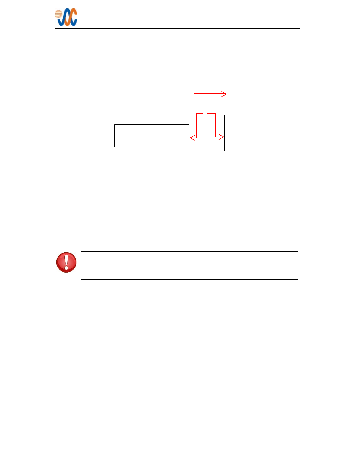
Stand Alone Intercom System. The diagram below describes the naming method
for the different systems.
wiJAC-P x x
The wiJAC-Px1 – N America consists of one JA65-001 Headset Adapter Master,
and up to four JA64-001 Headset Adapter Slaves.
The wiJAC-Px2 – Europe consists of one JA65-002 Headset Adapter Master,
and up to four JA64-002 Headset Adapter Slaves.
The wiJAC-Px3 – Japan consists of one JA65-003 Headset Adapter Master, and
up to four JA64-003 Headset Adapter Slaves.
Only paired units will operate together (see section 4)
System operating information is in section 5.2.
WARNING: JAC recommends that no battery operated device
should be relied upon as the sole method of communication in
cases where there is potential risk to life or limb.
1.1 Unpacking
Unpack the wiJAC™ box carefully, and ensure that it contains the following:
• one Wireless Headset Adapter Master, JAC P/N JA65-00x
• one to four Wireless Headset Adapter Slaves, JAC P/N JA64-00x
• one set of AAA rechargeable batteries for each unit
• one USB to Micro USB cable, JAC P/N CAB-USB-0003 for each unit.
• one wiJAC™ Quick Start User Guide, JAC P/N DOC-GUID-WIPXXU
• one wiJAC™ Quick Start Pairing Guide, JAC P/N DOC-GUID-WIPXXP
1.2 Verify Operating Region
The wiJAC-Pxx Wireless Intercom System operates using radio frequencies that
are authorized by government regulatory agencies. Ensure the region in which
you are operating the units matches the region marked on a label on the back of
each unit.
Number of Headsets
in the System (2 – 5)
Operating Region:
1 = N America
2 = Europe
3 = Japan
System Type:
P = Person to Person
wiJAC-Pxx Wireless Stand Alone Intercom System
Operating Manual
Page 2
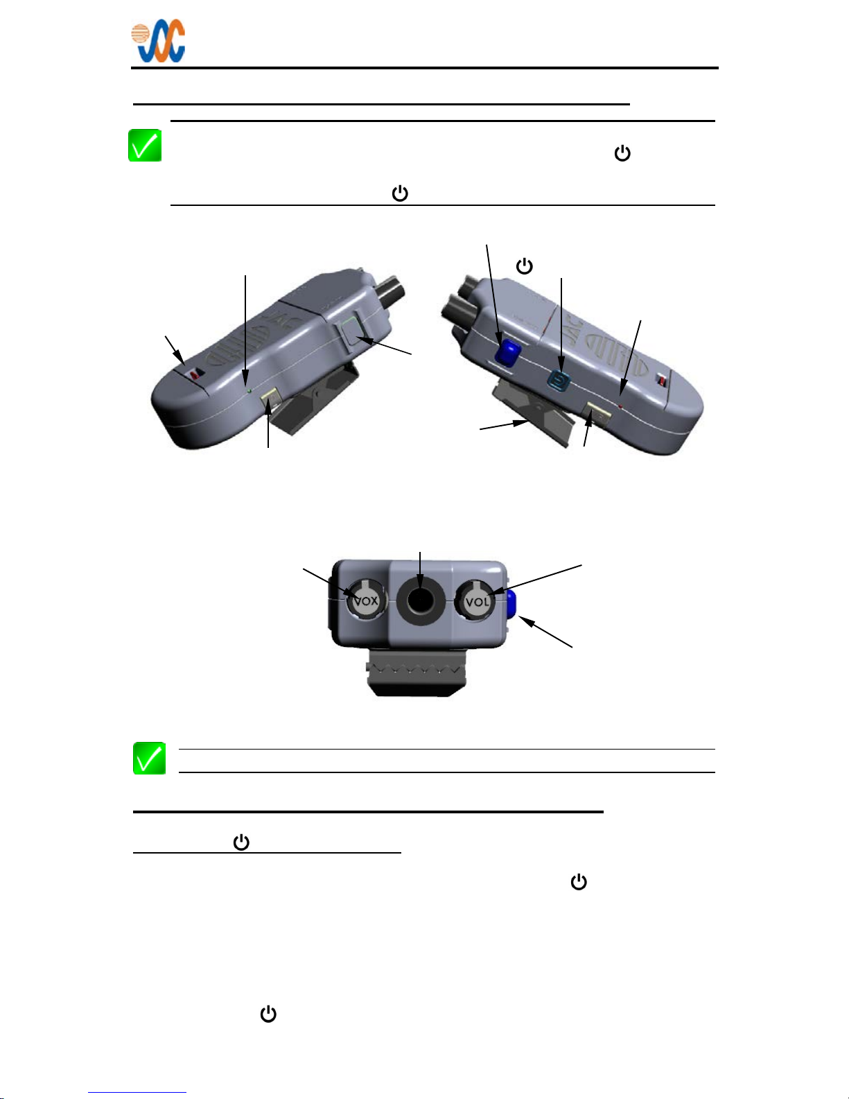
2 Headset Adapter Master/Slave (JA65/JA64)
Note: The JA65 Headset Adapter Master and JA64 Headset Adapter Slave
are superficially identical except for the colour of the ON/OFF button and
MSTR (master) or SLAV (slave) on the blanking plate. Each system
MUST utilize one JA65 (green
button).
Note: The units are shown in grey for clarity
3 Controls, Annunciators and Connectors
3.1 (ON/OFF) Button
The ON/OFF control is a push button switch marked with the symbol and is
located on the left side of the unit. To turn the unit on, press the ON/OFF button
once. To turn the unit off, press and hold the ON/OFF button until the PWR ON
and LOW BATT annunciators turn off (approximately three to five seconds).
The JA65 Headset Adapter Master has a GREEN ON/OFF button, and the JA64
Headset Adapter Slave has a GREY ON/OFF button. Each system must utilize
one JA65 (Green
button).
ON/OFF Control
Charging Port
LOW BATT
Annunciator (red)
Battery Lid
Release
ICS Push To Talk Button
Configuration Port
PWR ON
Annunciator (green)
Headset Jack
VOL
(Phones Volume
Control)
VOX
(Voice Operated
Switch Control)
Clothing
Clip
Fig 2-1, Right Side View
Fig 2-2, Left Side View
Fig 2-3, Top View
ICS PTT
(Blue Button
)
Blanking
Plate

wiJAC-Pxx Wireless Stand Alone Intercom System
Operating Manual
Page 3
3.2 VOX (Voice Operated Switch)
The Voice Operated Switch control is a rotary knob marked VOX located on the
top of the Headset Adapter. To reduce the level of the sound needed to route the
microphone audio to the other headset adapter(s), turn the VOX knob
counterclockwise (ccw). To increase the level of the sound needed, turn the VOX
knob clockwise (cw). Adjust this setting for proper VOX operation as ambient
noise levels change.
3.3 VOL (Phones Volume Control)
WARNING: Loud noise can cause hearing damage. Before using a
headset, set the volume to minimum, and then slowly increase it to a
comfortable listening level.
The volume control is a rotary knob marked VOL (volume) located on the top of
the headset adapters. To reduce the volume of the audio heard in the headset
rotate the VOL knob ccw. To increase the volume of the audio heard in the
headset rotate the VOL knob cw.
3.4 ICS PTT (Push To Talk) Button
The intercom Push To Talk button is a blue convex push button switch located on
the left side of the Headset Adapter. The ICS PTT markings are located on the
back and front of the unit. When the ICS PTT button is pressed and held, the
VOX threshold is overridden, and microphone audio is routed to any other paired
headset adapter(s).
3.5 Headset Jack
The headset jack is a TJT120 type connector on the top of the headset adapters.
Insert a U-174/U or U93A/U type Headset plug into the headset jack.
3.6 Connectors
3.6.1 IO Configuration Port (Dealers only)
This port is used by Approved dealer s and install er s to connect the unit to a
laptop or PC to enable configuration changes using the ProCS™ program.
3.6.2 PWR (Charging Port)
The Charging Port is a Micro-USB connector with a flexible cover labeled PWR
(power) on the left side of the unit. To charge NiMH batteries, connect a USB
(Universal Serial Bus) to Micro USB cable from the Charging Port to a USB
power source.
WARNING: Charging battery types other than NiMH or NiCad may
cause the batteries to leak or explode and cause damage or injury. If
non-NiMH or non-NiCad batteries are installed, do not connect the
Charging Port to a USB power source.

wiJAC-Pxx Wireless Stand Alone Intercom System
Operating Manual
Page 4
3.7 Annunciators
3.7.1 PWR ON (Power On)
The power on (PWR ON) annunciator is a green LED located on the right side of
the unit. In addition to indicating that the unit is turned on, this annunciator
indicates the connection status of paired units (see section 4.1)
3.7.2 LOW BATT (Low Battery Warning)
The low battery (LOW BATT) annunciator is a red LED located on the left side of
the unit. When a unit is turned on, the LOW BATT annunciator will illuminate for 2
seconds.
When the JA64 battery voltage is low the LOW BATT annunciator will flash once
every 1.5 s and a low battery notification (a triple beep) will be heard in the
headphones once every minute.
When the unit battery charge is less than or equal to the critical battery voltage,
the unit will turn off.
3.7.3 Battery Charge (not shown)
The JA64 and JA65 Battery Charge annunciators are two LEDs, one on each
side of the charging port under the flexible dust cover marked PWR.
The Fast Charge annunciator is a red light emitting diode (LED) that will
illuminate when the batteries are being charged at the maximum charge current.
The Top-Off Charge annunciator is a green LED that will illuminate when Fast
Charge mode is complete and the batteries are charged.
3.8 Other
3.8.1 Pairing Registration Number
The pairing registration number is marked on a label in on the back of the JA65.
JA64 Headset Adapters must be marked with the same pairing registration
number after pairing (see section 4.1).
3.8.2 Battery Lid Release
The battery lid release is a lever on the front of the unit recessed into the battery
lid (see section 6.1).
3.8.3 Clothing/Mounting Clip
The clothing clip is on the rear of the JA64/JA65 Headset Adapters. Ensure that
the units are attached securely.
wiJAC-Pxx Wireless Stand Alone Intercom System
Operating Manual
Page 5
4 Pairing and Purging Process
The wiJAC-Pxx Wireless Intercom Systems consist of one JA65 Headset
Adapter Master (green ON/OFF button), and up to four factory-paired JA64
Headset Adapter Slaves. Any additional Headset Adapter Slaves must be paired
with the Headset Adapter Master before the expanded system can function
correctly. Once pairing is complete, the three character Pairing Registration
Number from the back of the JA65 should be written on the label on the back of
each paired JA64 using a permanent marker. Ensure that the same number is
marked on each unit.
To locate the pair switch, the battery cover must be removed from the unit.
4.1 Pairing
The JA64/JA65 pairing process is described in the following steps:
1. Turn off the JA65 and any other JA64 previously paired with the JA65.
2. Turn on the JA65.
The JA65 enters the standby mode (Power Annunciator bl inks in s ets of
two or three flashes). If the Power Annunciator stays on continuously,
there is a JA64 still powered on and connected to the JA65. Please turn
off the JA64.
3. On the JA65, press and hold the Pair Switch (4 seconds) until the
Powe r and Low Battery Annunciators start flashing rapidly (10 flashes
/second). Release the Pair switch.
The JA65 enters the pairing mode (Power Annunciator is flashing at a
medium rate (5 flashes /second) and can now be paired with a JA64.
4. Turn on a JA64 to be paired with the JA65.
The JA64 enters the standby mode (Power Annunciator blinks in sets of
two or three flashes).
5. On the JA64, press and hold the Pair Switch (4 seconds) until the
Power and Low Battery Annunciators starts flashing rapidly (10 flashes
/second). Release the Pair switch.
The JA64 enters the pairing mode (Power Annunciator is now flashing at a
medium rate (5 flashes /second) and will complete the pairing process
automatically with the JA65.
The JA64 and JA65 indicate they have completed the pairing process when the
Power Annunciator is on continuously.
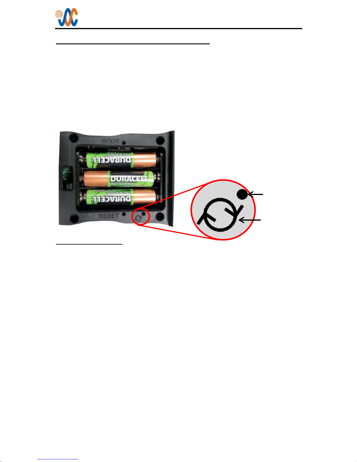
When the battery cover is removed,
the pair symbol and switch access
hole can be seen on the edge of the
compartment. Insert a straightened
paperclip into the hole to press the
button.
Switch Access
Pair Symbol

wiJAC-Pxx Wireless Stand Alone Intercom System
Operating Manual
Page 6
4.2 Purging
A JA65 that has already been paired with four JA64 headset adapters must be
purged to clear any existing pairings if it is necessary to replace one or more of
the headset adapters.
Note: This process clears ALL previously paired units from the JA65. All
JA64 units required for use in the system must then be paired with the JA65.
The purging process is described in the following steps:
1. Turn off the JA65 and any other JA64 previously paired with the JA65.
2. Turn on the JA65.
The JA65 enters the standby mode (Power Annunciator blinks in sets of
two or three flashes). If the Power Annunciator stays on continuously,
there is a JA64 still powered on and is connected to the JA65. Please turn
off the JA64.
3. On the JA65, press and hold the Pair Switch (>8 seconds) until the
Power and Low Battery Annunciators turn off. Release the Pair switch.
The JA65 enters the purge mode (Power Annunciator blinks in sets of
three flashes). Wait for the JA65 to finish purging all paired JA65 from its
memory (approximately 10 seconds).
4. Turn off the JA65.
5. Turn on the JA65. If the Power Annunciator blinks in sets of three
flashes, the purging process was successful. If the Power Annunciator
blinks in sets of two flashes, repeat the purging process from step 1.
CAUTION: To minimize the risk of system malfunction, a JA64 must
not be paired with more than one JA65 at a time.

wiJAC-Pxx Wireless Stand Alone Intercom System
Operating Manual
Page 7
5 Connecting the wiJAC™ System
Note: The wiJAC-Pxx Wireless Intercom System Person to Person consists
of one JA65 Headset Adapter Master and up to four JA64 Headset Adapter
Slaves. Only paired units will operate together (see section 4).
A headset is inserted into the jack on the JA64/JA65 Headset Adapter, which is
clipped to the user's belt or clothing. Headsets are not included.
5.1 wiJAC™ Set-up and Connection
5.1.1 Insert Batteries
Ensure the batteries for all units are fully charged and installed in the battery
compartment with the correct polarity, and the battery lid is secured (section 6).
5.1.2 Attach JA64 and JA65 Headset Adapters
Insert a headset with a U-174/U or U93A/U type plug into the JA64/JA65 Headset
Adapter jack.
5.1.3 Turn On Paired Adapters and Verify Connection
On the JA65 Headset Adapter Master, turn the VOL knob fully counterclockwise
to minimum. Turn on the JA64 Headset Adapter Slave(s). On all units, the PWR
ON and LOW BATT annunciators will illuminate for two seconds.
• When a unit is turned on, the PWR ON annunciator will illuminate for 2
seconds, and the unit will start to search for its paired unit.
• While the unit is searching for its paired unit the PWR ON annunciator will
triple-flash every 1.5 seconds.
• When the unit is connecting to its paired unit, the annunciator wills double-
flash every 1.5 s until connection is established.
• After connection, the annunciator will illuminate steady green until the unit is
turned off.
5.1.4 Verify System Audio Operation
Adjust VOX control on the JA64 and JA65 Headset Adapters fully ccw and rotate
the VOL control to achieve a comfortable listening level. Confirm that the
microphone audio is live - all microphone audio is heard in the paired JA64/JA65
phones. Confirm that the audio level increases as the VOL control is rotated
clockwise and decreases as the VOL control is rotated counterclockwise.
Adjust VOX control on the JA64/JA65 Headset Adapters fully clockwise and
confirm that the microphone audio is off. Adjust the Headset Adapter's VOX
control for a comfortable speaking level.
Press the JA64 or JA65 Headset Adapter's ICS PTT button and confirm that
microphone audio is heard in all the paired JA64/JA65 phones.

wiJAC-Pxx Wireless Stand Alone Intercom System
Operating Manual
Page 8
5.2 wiJAC™ System Operation
Note: Operation for the JA64 Slave and JA65 Master Headset Adapters is
identical, but each system MUST contain a JA65 Master (green ON/Off
button).
5.2.1 Listening Operation
The Headset Adapter Phones Volume (VOL) controls the level of audio heard in
the headset's ear phones. As ambient noise levels change, the volume can be
adjusted.
5.2.2 VOX Speaking Operation
To use the JA64/JA65 Headset Adapter hands-free, adjust the VOX control so
that the microphone audio is turned on when speaking into the headset's
microphone at a comfortable level, or at a level to keep the ambient noise from
turning on the microphone audio.
5.2.3 ICS PTT Speaking Operation
To use the JA64/JA65 Headset Adapter in high-noise environments, adjust the
VOX control fully clockwise. To communicate, press and hold the ICS PTT button
and speak in to the headset's microphone.
5.2.4 Live Speaking Operation
To use the JA64/JA65 Headset Adapter so that the microphone audio is always
turned on, adjust the VOX control fully counterclockwise.
5.2.5 Low Battery Warning
When the unit's battery charge is low, the LOW BATT annunciator will flash
every 1.5 seconds. When the JA64 Headset Adapter battery charge is low, a
triple-beep will be heard in the headset once every minute.
Note: JAC recommends that the batteries should be charged or replaced
immediately when the LOW BATT warning illuminates during use.
When the battery charge level is critical, the unit will turn off. When one unit is off
the other unit will begin searching for its paired unit and its PWR ON annunciator
will flash.
5.2.6 Operation during Charging
The units will still operate while the Charging Port is connected to a USB power
source, but the batteries will charge at a slower rate. Additional noise may be
heard on the audio system while the Charging Port is connected to a USB power
source.

wiJAC-Pxx Wireless Stand Alone Intercom System
Operating Manual
Page 9
5.2.7 Loss of Audio
If there is no audio heard in the headset, check the PWR ON annunciator on the
JA64 and the JA65 Headset Adapters. If a unit is off, turn it on and verify
connection and operation.
If the battery charge is low, replace or recharge the batteries or remove the
wiJAC system.
If audio is unintelligible, discontinue use of the wiJAC system until
troubleshooting can be carried out.
5.2.8 Battery Life
The operating duration of the wiJAC-Pxx system with fully charged batteries
before battery replacement is required depends on the following factors:
• Distance between Headset Adapter Master and Headset Adap ter Slaves:
The closer together the units are the lower the radio frequency (RF) power
required for connection. This will increase the battery life.
• Obstacles between the Headset Adapter Master and H eadset A dapt er
Slaves:
Minimising the aircraft metal structures, human bodies, cargo and other
obstacles between the units will reduce the RF power needed for connection
and increase the battery life.
• Charge capacity of the batteries installed:
The higher the capacity of the batteries, typically specified as 500 to 1000
mAh (milliamp-hours), the longer the battery life.
• The type of batteries installed and the operating temperature:
During low temperature operation, rechargeable batteries will lose capacity.
When operating in low temperatures use alkaline batteries for a longer
battery life.
• The phones volume level and usage rate:
The lower the volume level and the less often audio is output to the phones,
the longer the battery life.

wiJAC-Pxx Wireless Stand Alone Intercom System
Operating Manual
Page 10
6 Batteries
WARNING: Charging battery types other than NiMH or NiCad may
cause the batteries to leak or explode and cause damage or injury.
If non-NiMH or non-NiCad batteries are installed, do not connect
the Charging Port to a USB power source.
The JA64 and JA65 each require three AAA batteries. JAC recommends
Duracell 800 mAh (or higher) NiMH or Duracell alkaline batteries for use in the
wiJAC™ system to obtain the typical battery life.
Removal of the batteries WILL NOT change any internal configuration of the unit.
Note: Rechargeable batteries MUST be charged before first use.
6.1 Inserting or Replacing the Batteries
Retaining tabs
To replace the batteries (both units
the same), remove the battery cover
by pressing the battery lid release
towards the JAC logo, lifting the
lower end of the cover, and then
gently prying the lid up and away
from the body to release the two tabs
from the retaining slots.
Remove the batteries and insert fully
charged batteries, matching the
polarity marked on the battery
holder.
Battery Lid Release
6.2 Charging Batteries in the Unit
To charge rechargeable batteries in the unit, connect the Charging Port to a USB
power source using the USB to Micro-USB cable (CAB-USB-0003). If turned on
during charging, the unit draws its power from the charging source, not the
batteries, but battery charging will take longer. When charging is complete, the
'Top Off' Charge annunciator will illuminate green.
It should be possible to charge the unit via most USB power sources but this
cannot be guaranteed for any products not made by or purchased from JAC.
Where space allows, JAC recommends the JAC JA72-006 6 Dzus Glove Box
with USB connector (see section 7.1)
Note: The batteries will charge whether the JA64/JA65 is switched on or
switched off. Battery charging will take longer if the unit is switched on.

wiJAC-Pxx Wireless Stand Alone Intercom System
Operating Manual
Page 11
6.3 Charging Operation – via Battery Charger
The batteries may be removed from the unit for charging in a separate battery
charger. Removal of the batteries WILL NOT change any internal configuration of
the unit.
Note: The JA64 and JA65 will only charge the batteries when the internal
temperature is within 0 to 40 °C
6.4 Battery Cautions and Warnings
CAUTION: Follow these guidelines to prolong battery life and minimize
the risk of unit malfunction.
Do not leave batteries uncharged for long periods of time.
Do not leave batteries charging for extended periods (more than
48 hours)
To ensure that the unit functions correctly, insert the new
batteries with the positive and negative poles aligned as
indicated in the battery compartment.
When replacing the batteries, use only new or fully charged
batteries.
Do not mix old and new batteries as this can cause battery
leakage and/or damage to the unit.
Do not mix battery types.
WARNING: Follow these guidelines to prolong battery life, and
minimize the risk of fire, chemical burns, electrolyte leaks and/or
injury.
FOLLOW the manufacturer's instructions for care and disposal of
batteries.
DO NOT use sharp objects to remove the batteries.
DO NOT disassemble, puncture, burn or in any other way
damage the batteries.
DO NOT let children handle the batteries.
USE ONLY recommended battery chargers.
USE ONLY recommended replacement batteries.

wiJAC-Pxx Wireless Stand Alone Intercom System
Operating Manual
Page 12
7 Accessories
7.1 JA72-005 Glove Box with USB connector
The JA72 Glove Box with USB Charger allows an aircraft owner/operator to
utilize an empty portion of the instrument panel for storage.
A USB 2.0 Type A receptacle is provided to supply 5 Vdc power up to 2 Amps,
and a 3.5mm stereo jack can be connected to the aircraft's audio system.
7.2 ProCS™ Product Configuration Software
ProCS™ Product Configuration Software and a ProCS™ connection cable are
available to approved dealers and installers.
7.3 Battery Charger Recommendations
To charge AAA NiMH batteries, JAC recommends the charger should have
individual cell charging (so that three batteries may be charged at once), an
automatic shut-off feature and a charge time of two to six hours.
Always follow the manufacturer’s recommendations for use of batteries and
battery chargers.

wiJAC-Pxx Wireless Stand Alone Intercom System
Operating Manual
Page 13
8 Warranty
Locate and complete the online warranty registration form from the JAC website:
www.jupiteravionics.com/warrantyregistration
These products manufactured by JAC are warranted to be free of defects in
workmanship or performance for 1 year from the date of purchase from an
authorized JAC dealer. This warranty covers the cost of all materials and labour
to repair or replace the unit, but does not include the cost of transporting the
defective unit to and from JAC or its designated warranty repair centre. This
warranty does not cover failures due to abuse, misuse, accident, incorrect battery
use/installation, or unauthorized alteration or repairs.
Contact JAC for any questions regarding this warranty and how it applies to your
unit(s). JAC is the final arbiter concerning warranty issues.
Contact JAC for a Returned Materials Authorisation Form (RMA) prior to shipping
any products for repair. This form can be downloaded from our website at
www.jupiteravionics.com/dealersrmaform
9 FCC Compliance Statement
This device complies with Part 15 of the FCC Rules.
Operation is subject to the following two conditions:
1) this device may not cause harmful interference, and
2) this device must accept any interference received, including interference that may
cause undesired operation of the device.
Module transmetteur ID IC: 9576A-SC14A
Son fonctionnement est soumis aux deux conditions suivantes:
1) cet appareil ne doit pas causer d’interférences nuisibles et
2) cet appareil doit accepter toute interference recue, y compris les interferences qui
peuvent pertuber le fonctionnement.
Changes or modifications to the equipment not expressly approved by the Party
responsible for compliance could void the user's authority to operate the equipment.
NOTE: This equipment has been tested and found to comply with the limits for a Class B
digital device, pursuant to Part 15 of the FCC Rules. These limits are designed to provide
reasonable protection against harmful interference in a residential installation.
This equipment generates, uses and radiates radio frequency energy and, if not installed
and used in accordance with the instructions, may cause harmful interference to radio
communications. There is no guarantee that interference will not occur in a particular
installation. If this equipment does cause harmful interference to radio reception, which can
be determined by turning the equipment off and on, the user is encouraged to try to correct
the interference by one or more of the following measures:
• Increase the separation between the equipment and the interfered receiver or antenna.
• Turn the equipment off and remove from the aircraft.
• Consult Jupiter Avionics Corp or an experienced avionics technician for help.
Note: Privacy of communications may not be ensured when using this equipment.

Jupiter Avionics Corporation
1959 Kirschner Road
Kelowna BC
Canada V1Y 4N7
Tel: +1 778 478 2232
Toll-Free: 1 855 478 2232
www.jupiteravionics.com
TO ONLINE DATASHEET
TO ONLINE DATASHEET
TO ONLINE DATASHEET
TO ONLINE DATASHEET
TM
-
Pxx
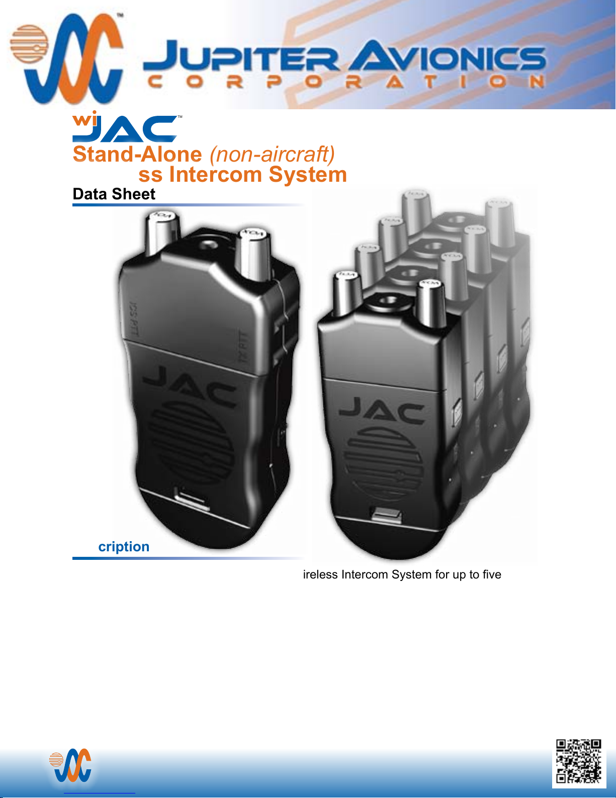
Stand-Alone (non-aircraft)
Wireless Intercom System
Data Sheet
Description
The wiJAC-Pxx system is a Stand-Alone Wireless Intercom System for up to ve
users, and provides a wireless full-duplex, hands-free audio network. The components
connect to standard aircraft headsets and attach to the users’ belts, allowing operators
free movement. Adapters are available for different headset connector styles and impedances.
Communications range is typically 100 meters (200 meters for European model). The
system features only essential controls to ensure ease of operation. (VOX and Volume
control knobs, and On/Off and PTT buttons)
The wiJAC-Pxx system is designed to operate independently, and does not use any
DOC-DATA-PXX Artwork Rev C.pdf
aircraft audio connections.
TM
1959 Kirschner Rd, Kelowna, BC V1Y 4N7, Canada
Tel: +1 778-478-2232 Toll-Free 1 855-478-2232
www.jupiteravionics.com
Features
The wiJAC™ system is factory programmed with default settings that are suitable for most general
(aviation-type) high impedance headsets. If it is necessary to modify the balanced phones/microphone
input/output levels, this can be carried out by a JAC Dealer using JAC’s proprietary ProCS™ software.
A conguration port is provided to support this function.
A light on each unit indicates when the RF communication link is established, and a micro USB charging
port is provided for connection to a USB charging source. Charging cables and rechargeable batteries are
included with each system.
Multiple systems can be co-located without interference. An encrypted radio link ensures secure
communications. The units are designed for NATO style aircraft connectors. A selection of adapter cables
is available for use with other connector styles.
The wiJAC-Px1 system comprises a JA65-001 and a number of JA64-001’s and is for use in North America.
The wiJAC-Px2 system comprises a JA65-002 and a number of JA64-002’s and is for European use.
TM
-
Pxx
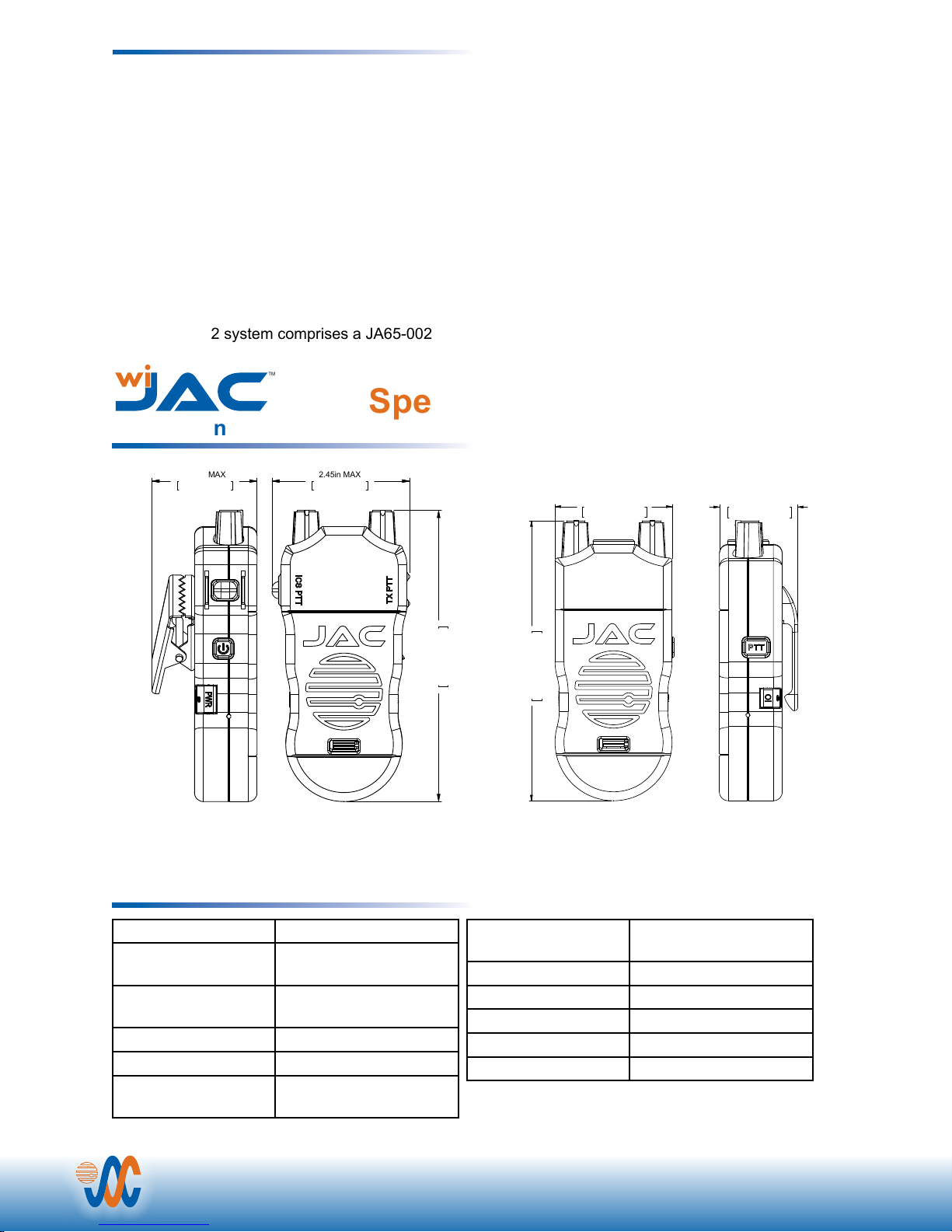
Specications
Installation
U-92A/U type
connector mates
with U93A/U
and equivalent
1.90in MAX
48.3mm MAX
2.45in MAX
62.2mm MAX
JA65-00x Wireless Aircraft Headset Adapter
Weight: 0.46 lb. 0.209 Kg Max
Environment and Performance
U-92A/U type
connector mates
2.06in MAX
52.3mm MAX
130.8mm MAX
5.15in MAX
127.0mm MAX
5.00in MAX
1.36in MAX
34.5mm MAX
with U93A/U
and equivalent
JA64-00x Wireless Aircraft Headset Adapter
Weight: 0.39 lb. 0.178 Kg Max
Batteries AAA (3 per unit)
Charging Electrical
Power
Temperature
+5 Vdc @ 200mA max
(USB Power Source)
-15 °C to +50 °C
-40 °C to +50 °C
Altitude 25,000 ft. max
Humidity 95%
Microphone 150 Ohms amplied
Dynamic
TM
Tel: +1 778-478-2232 Toll-Free 1 855-478-2232
Printed in Canada
Vibration Per DO160G
Cat [(SBM)(U2FF1)]
Range wiJAC-Px1 100 m (typical)
Range wiJAC-Px2 200 m (typical)
Battery Life 6 to 8 hr (typical)
Shock 20g (any axis)
Headphone 100 mW into 150 Ohms
© 2015 Jupiter Avionics Corporation
1959 Kirschner Rd, Kelowna, BC V1Y 4N7
www.jupiteravionics.com
 Loading...