

Page 1
UC-240 Twelve-channel receiver
The UC-240 is a 12-channel receiver of signals from TP-60TX
wireless thermostats or from JA-60 wireless detectors. The receiver
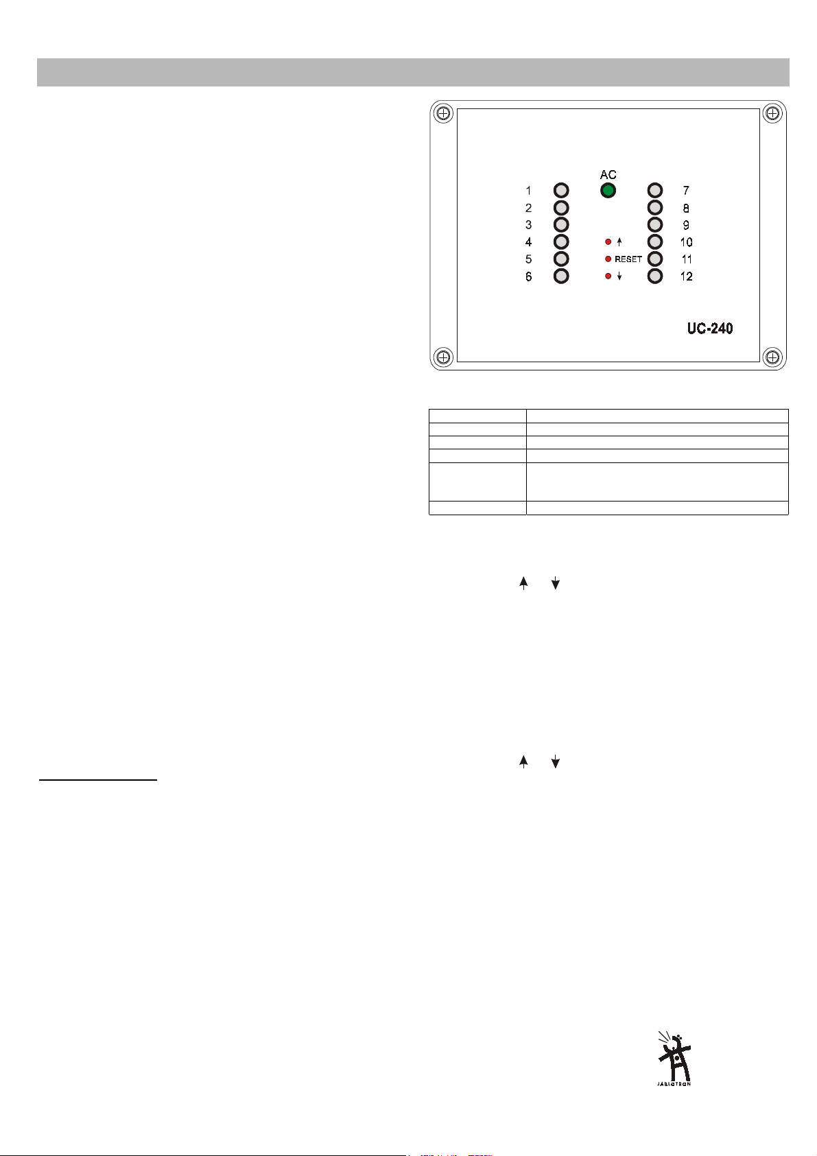
has 12 output relays which can be used to control various devices. LEDs
on the receiver’s front cover indicate the status of each output channel.
When used with wireless thermostats, the UC-240 can efficiently
control multi-zone heating and cooling systems.
JA-60M wireless detectors can be used to control the UC-240’s
output relays remotely from any switching device (switch, micro switch
sensor etc.). This can be convenient for automation or control tasks.
The UC-240 can also receive signals from JA-60S wireless smoke
sensors and JA-60G gas leak sensors.
Specification
Power supply: 15 – 30 V DC or 15-24 V AC
Internal self consumption: 0.05 A (all relays OFF)
0.4 A (all relays ON)
Max. supply current: 5.5 A (including 5 A which can be
Internal current protection: fuse F 6.3 A
Max. output relay load: 0.4 A per relay when outputs are
Output +12VDC: 12 V DC stabilized, max. 200 mA
Output +U: rectified AC power voltage, max.5 A
Receiver radio frequency: 433.9 MHz, ISM EN 300220
Working distance: max.100 m in an open area
Dimensions: 165 x 125 x 75 mm (w/o antenna)
Mechanical robustness: IK08 according to EN 50102
EMC EN 300683
Working environment: IP20 EN 60529
Humidity: max. 85 %
Working temperature): -10 to +40
Installation
1. Remove the 4 screws holding the front cover and open the housing.
Unplug the internal cable and remove the cover.
2. Attach the UC-240 in a desired place with two screws (provided).
3. Route cables through the housing and connect them to the
terminals (see terminal description and examples of wiring).
4. Plug in the front panel cable and reattach the front cover to the
housing.
Note: Do not locate any cable close to the receiver antenna and do
not install any other UC-240 closer than 2 meters (this could shorten the
working distance). If you need a receiver with additional channels, please
contact your supplier.
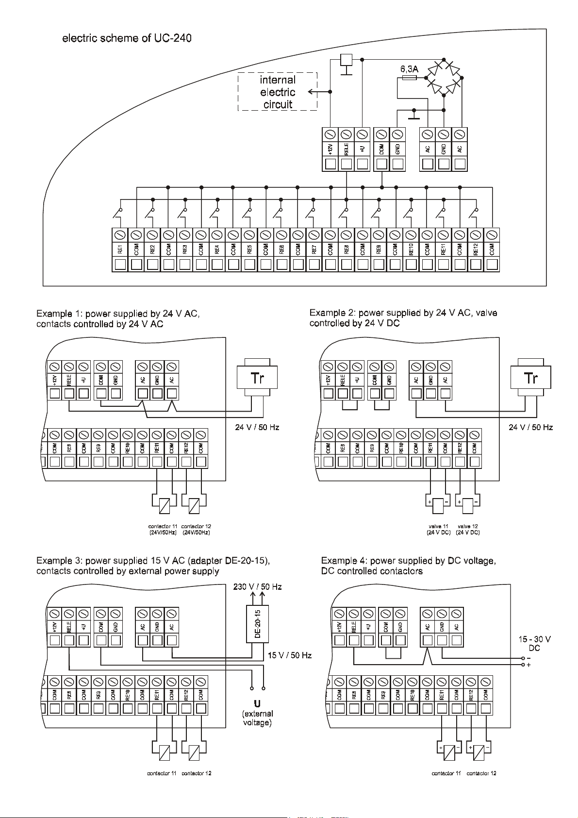
Terminals description:
AC, AC
– AC power input 15 –24 VAC. If powered with DC
voltage, connect the positive pole to the left AC terminal
and the negative pole to the GND terminal
+12V, GND
+U
– stabilized 12 V DC output, max. 0.2A (for optional use)
– built in rectifier output (rectified AC voltage, max. 5A -
limited also with the capacity of the power supplier)
RELE
– common power inlet for all output relay contacts (if
powered from the built in rectifier, connect this terminal
to the +U terminal)
RE1- RE12
COM
– normally opened output relay contacts
– 13 common terminals to connect common poles of the
external load (actuators, power relay coils etc.)
Indicators
Green LED AC indicates the presence of the receiver’s power supply.
When lit, the receiver is powered.
used for external load = actuators,
power relay coils etc.)
powered by the built in rectifier (+U
terminal)
0.5A / 60 V per relay when outputs
are powered by an external power
supply
o
C
Indicators
1 to 12
indicate the status of the output channels (relays).
LED 1 - 12 Description
Off Channel is not used (no transmitter is enrolled)
Steady Green Channel has a transmitter enrolled, relay is off
Steady Red Relay is on (activated by the enrolled transmitter)
Flashing Green Communication with the enrolled transmitter is
down (Low battery in transmitter, radio interference
etc.)
Flashing Red Learning mode (to enroll a transmitter)
Enrollment of transmitters
For each channel of the receiver, a transmitter (thermostat or wireless
detector) can be enrolled the following way:
•
using button
(current channel will be indicated by its LED flashing)
•
install batteries to the transmitter (thermostat or detector). When
powered, the transmitter generates an enrollment signal and its code
is stored in the selected receiver channel’s memory
•
enrollment of the transmitter is confirmed by the constant lighting of
the green LED.
Only one transmitter can be enrolled to each UC-240 channel. The
transmitter can be enrolled to multiple receivers with out any restrictions.
If you try to enroll a new transmitter to an occupied channel, the new
transmitter will be stored and the former one will be erased.
Erasing of a transmitter
To erase an existing transmitter,:
•
using button
(current channel will be indicated by its LED flashing)
•
press the RESET button and the corresponding LED will turn off
Use and Maintenance
All enrolled transmitters (thermostats and detectors) transmit regular
checking signals. If the receiver does not receive the signal of an enrolled
transmitter for a certain period, it will indicate that communication with this
item is down (flashing green LED) and the corresponding relay will turn
off.
A reason for the lost connection can be low batteries in the transmitter.
Average life time of the transmitter's batteries is about 1 year. Each
transmitter checks its battery’s conditions and signals in advance if the
batteries are reaching a critically low state (see the transmitter manual for
details).
Another reason of possible connection failure can be from radio signal
interference in the working band of the receiver. In such a case the
UC-240 will usually indicate loss of communication with a multiple number
of transmitters. In this situation, check if there is any non approved radio
communicating device in the working range of the receiver.
Warning: manufacturer is not responsible for
any damage caused by improper installation
or non suitable use of this product.
or (UP or down) select the desired channel
or (UP or down) select the desired channel
Pod Skalkou 33
466 01 Jablonec nad Nisou
Czech Republic
tel.: 420-428-346911
fax: 420-428-313183
expor t@jablot ron.cz
www.jablotron. cz
UC-240 TWELVE-CHANNEL RECEIVER 1/2 MFD51102
Page 2
UC-240 TWELVE-CHANNEL RECEIVER 2/2 MFD51102
 Loading...